KR102576842B1 - Robot and electronic device for performing hand-eye calibration - Google Patents
Robot and electronic device for performing hand-eye calibration Download PDFInfo
- Publication number
- KR102576842B1 KR102576842B1 KR1020170001549A KR20170001549A KR102576842B1 KR 102576842 B1 KR102576842 B1 KR 102576842B1 KR 1020170001549 A KR1020170001549 A KR 1020170001549A KR 20170001549 A KR20170001549 A KR 20170001549A KR 102576842 B1 KR102576842 B1 KR 102576842B1
- Authority
- KR
- South Korea
- Prior art keywords
- external object
- robot
- camera
- coordinate system
- end effector
- Prior art date
- Legal status (The legal status is an assumption and is not a legal conclusion. Google has not performed a legal analysis and makes no representation as to the accuracy of the status listed.)
- Active
Links
Images






Classifications
-
- B—PERFORMING OPERATIONS; TRANSPORTING
- B25—HAND TOOLS; PORTABLE POWER-DRIVEN TOOLS; MANIPULATORS
- B25J—MANIPULATORS; CHAMBERS PROVIDED WITH MANIPULATION DEVICES
- B25J9/00—Program-controlled manipulators
- B25J9/16—Program controls
- B25J9/1679—Program controls characterised by the tasks executed
- B25J9/1692—Calibration of manipulator
-
- B—PERFORMING OPERATIONS; TRANSPORTING
- B25—HAND TOOLS; PORTABLE POWER-DRIVEN TOOLS; MANIPULATORS
- B25J—MANIPULATORS; CHAMBERS PROVIDED WITH MANIPULATION DEVICES
- B25J15/00—Gripping heads and other end effectors
- B25J15/0004—Gripping heads and other end effectors with provision for adjusting the gripped object in the hand
-
- B—PERFORMING OPERATIONS; TRANSPORTING
- B25—HAND TOOLS; PORTABLE POWER-DRIVEN TOOLS; MANIPULATORS
- B25J—MANIPULATORS; CHAMBERS PROVIDED WITH MANIPULATION DEVICES
- B25J19/00—Accessories fitted to manipulators, e.g. for monitoring, for viewing; Safety devices combined with or specially adapted for use in connection with manipulators
- B25J19/02—Sensing devices
- B25J19/021—Optical sensing devices
- B25J19/023—Optical sensing devices including video camera means
-
- B—PERFORMING OPERATIONS; TRANSPORTING
- B25—HAND TOOLS; PORTABLE POWER-DRIVEN TOOLS; MANIPULATORS
- B25J—MANIPULATORS; CHAMBERS PROVIDED WITH MANIPULATION DEVICES
- B25J9/00—Program-controlled manipulators
- B25J9/02—Program-controlled manipulators characterised by movement of the arms, e.g. cartesian coordinate type
- B25J9/023—Cartesian coordinate type
-
- B—PERFORMING OPERATIONS; TRANSPORTING
- B25—HAND TOOLS; PORTABLE POWER-DRIVEN TOOLS; MANIPULATORS
- B25J—MANIPULATORS; CHAMBERS PROVIDED WITH MANIPULATION DEVICES
- B25J9/00—Program-controlled manipulators
- B25J9/16—Program controls
- B25J9/1656—Program controls characterised by programming, planning systems for manipulators
- B25J9/1664—Program controls characterised by programming, planning systems for manipulators characterised by motion, path, trajectory planning
-
- B—PERFORMING OPERATIONS; TRANSPORTING
- B25—HAND TOOLS; PORTABLE POWER-DRIVEN TOOLS; MANIPULATORS
- B25J—MANIPULATORS; CHAMBERS PROVIDED WITH MANIPULATION DEVICES
- B25J9/00—Program-controlled manipulators
- B25J9/16—Program controls
- B25J9/1694—Program controls characterised by use of sensors other than normal servo-feedback from position, speed or acceleration sensors, perception control, multi-sensor controlled systems, sensor fusion
- B25J9/1697—Vision controlled systems
-
- G—PHYSICS
- G06—COMPUTING OR CALCULATING; COUNTING
- G06T—IMAGE DATA PROCESSING OR GENERATION, IN GENERAL
- G06T7/00—Image analysis
- G06T7/70—Determining position or orientation of objects or cameras
-
- G—PHYSICS
- G06—COMPUTING OR CALCULATING; COUNTING
- G06T—IMAGE DATA PROCESSING OR GENERATION, IN GENERAL
- G06T7/00—Image analysis
- G06T7/80—Analysis of captured images to determine intrinsic or extrinsic camera parameters, i.e. camera calibration
-
- G—PHYSICS
- G06—COMPUTING OR CALCULATING; COUNTING
- G06T—IMAGE DATA PROCESSING OR GENERATION, IN GENERAL
- G06T2207/00—Indexing scheme for image analysis or image enhancement
- G06T2207/30—Subject of image; Context of image processing
- G06T2207/30204—Marker
- G06T2207/30208—Marker matrix
Landscapes
- Engineering & Computer Science (AREA)
- Robotics (AREA)
- Mechanical Engineering (AREA)
- Computer Vision & Pattern Recognition (AREA)
- Physics & Mathematics (AREA)
- General Physics & Mathematics (AREA)
- Theoretical Computer Science (AREA)
- Multimedia (AREA)
- Manipulator (AREA)
Abstract
로봇이 개시된다. 일 실시 예에 따른 로봇은 복수의 조인트(joint), 복수의 조인트 중 적어도 일부에 의해 회전 가능하도록 서로 연결된 복수의 암 섹션(arm section), 및 복수의 조인트 중 하나와 연결되고 외부 물체를 파지(grasp)할 수 있도록 구성된 엔드 이펙터(end effector)를 포함하는 로봇 암(robot arm), 카메라와 무선 또는 유선으로 연결된 통신 인터페이스 및 로봇 암 및 통신 인터페이스와 전기적으로 연결된 제어 회로를 포함하고, 제어 회로는, 엔드 이펙터의 중심이 외부 물체의 중심과 일치하도록 외부 물체가 엔드 이펙터에 의해 파지된 후, 외부 물체를 작업대 상에 배치하도록 로봇 암을 제어하고, 카메라에 의해 촬영된 외부 물체에 대한 영상으로부터 카메라의 좌표계 내의 외부 물체의 중심점의 좌표를 획득하고, 외부 물체가 작업대 상에 배치될 때 로봇의 기저 좌표계 내의 엔드 이펙터의 좌표 및 카메라의 좌표계 내의 외부 물체의 중심점의 좌표에 기초하여 엔드 이펙터의 좌표계와 카메라의 좌표계 사이의 관계를 정의하는 캘리브레이션 파라미터를 산출할 수 있다. 이 외에도 명세서를 통해 파악되는 다양한 실시 예가 가능하다.The robot starts. A robot according to an embodiment includes a plurality of joints, a plurality of arm sections connected to each other so as to be rotatable by at least some of the plurality of joints, and a robot connected to one of the plurality of joints and holding an external object ( A robot arm including an end effector configured to grasp, a communication interface connected wirelessly or wired to a camera, and a control circuit electrically connected to the robot arm and the communication interface, the control circuit comprising: After the external object is gripped by the end effector so that the center of the end effector coincides with the center of the external object, the robot arm is controlled to place the external object on the workbench, and the camera determines the image of the external object captured by the camera. Acquire the coordinates of the center point of the external object in the coordinate system of the workbench, and when the external object is placed on the workbench, the coordinates of the end effector in the base coordinate system of the robot and the coordinates of the center point of the external object in the coordinate system of the camera are used to obtain the coordinates of the end effector's coordinate system and Calibration parameters that define the relationship between the camera's coordinate systems can be calculated. In addition to this, various embodiments identified through the specification are possible.
Description
본 문서에서 개시되는 실시 예들은 로봇의 핸드-아이 캘리브레이션을 수행하기 위한 기술과 관련된다.Embodiments disclosed in this document relate to technology for performing hand-eye calibration of a robot.
로봇 시스템은 외부 물체를 파지(grasping)하기 위한 로봇 암 및 외부 물체를 촬영하기 위한 카메라를 포함할 수 있다. 로봇 시스템의 운용을 위해서는 로봇 암에 포함된 엔드 이펙터(end effector)의 좌표계와 카메라의 좌표계 사이의 변환 관계를 산출하기 위한 핸드-아이 캘리브레이션이 수행될 수 있다. 핸드-아이 캘리브레이션을 수행하기 위해서는 특정 지점에 대한 엔드 이펙터의 좌표계 내의 좌표 및 카메라의 좌표계 내의 좌표가 요구될 수 있다.The robotic system may include a robot arm for grasping an external object and a camera for photographing the external object. For operation of a robot system, hand-eye calibration can be performed to calculate the transformation relationship between the coordinate system of the end effector included in the robot arm and the coordinate system of the camera. In order to perform hand-eye calibration, coordinates within the end effector's coordinate system and coordinates within the camera's coordinate system for a specific point may be required.
핸드-아이 캘리브레이션을 위해서는 복수의 지점에 대한 엔드 이펙터의 좌표계 내의 좌표들 및 카메라의 좌표계 내의 좌표들이 요구될 수 있다. 종래의 로봇 시스템에서 상술한 좌표들은 로봇 시스템의 사용자가 직접 로봇 시스템을 조작함으로써 획득될 수 있다. 로봇 시스템의 사용자의 조작에 의해 상술한 좌표들을 획득하기 위해서는 다수의 인력 및 긴 시간이 소요될 수 있다.Hand-eye calibration may require coordinates within the end effector's coordinate system and coordinates within the camera's coordinate system for a plurality of points. In a conventional robot system, the above-described coordinates can be obtained by the user of the robot system directly manipulating the robot system. It may take a lot of manpower and a long time to acquire the above-mentioned coordinates by manipulating the robot system by the user.
본 문서에서 개시되는 실시 예들은, 전술한 문제 및 본 문서에서 제기되는 과제들을 해결하기 위해, 핸드-아이 캘리브레이션을 위한 사용자의 개입을 감소시킬 수 있고 소요 시간을 단축시킬 수 있는 로봇, 전자 장치 및 방법을 제공하기 위한 것이다.Embodiments disclosed in this document are robots, electronic devices, and devices that can reduce user intervention and shorten the time required for hand-eye calibration in order to solve the problems described above and the problems raised in this document. It is intended to provide a method.
본 문서에 개시되는 일 실시 예에 따른 로봇은 복수의 조인트(joint), 복수의 조인트 중 적어도 일부에 의해 회전 가능하도록 서로 연결된 복수의 암 섹션(arm section), 및 복수의 조인트 중 하나와 연결되고 외부 물체를 파지(grasp)할 수 있도록 구성된 엔드 이펙터(end effector)를 포함하는 로봇 암(robot arm), 카메라와 무선 또는 유선으로 연결된 통신 인터페이스 및 로봇 암 및 통신 인터페이스와 전기적으로 연결된 제어 회로를 포함하고, 제어 회로는, 엔드 이펙터의 중심이 외부 물체의 중심과 일치하도록 외부 물체가 엔드 이펙터에 의해 파지된 후, 외부 물체를 작업대 상에 배치하도록 로봇 암을 제어하고, 카메라에 의해 촬영된 외부 물체에 대한 영상으로부터 카메라의 좌표계 내의 외부 물체의 중심점의 좌표를 획득하고, 외부 물체가 작업대 상에 배치될 때 로봇의 기저 좌표계 내의 엔드 이펙터의 좌표 및 카메라의 좌표계 내의 외부 물체의 중심점의 좌표에 기초하여 엔드 이펙터의 좌표계와 카메라의 좌표계 사이의 관계를 정의하는 캘리브레이션 파라미터를 산출할 수 있다.A robot according to an embodiment disclosed in this document is connected to a plurality of joints, a plurality of arm sections rotatably connected to each other by at least some of the plurality of joints, and one of the plurality of joints. A robot arm including an end effector configured to grasp an external object, a communication interface connected wirelessly or wired to a camera, and a control circuit electrically connected to the robot arm and the communication interface. And, the control circuit controls the robot arm to place the external object on the workbench after the external object is gripped by the end effector so that the center of the end effector coincides with the center of the external object, and the external object photographed by the camera Obtain the coordinates of the center point of the external object in the camera's coordinate system from the image, and when the external object is placed on the workbench, based on the coordinates of the end effector in the robot's base coordinate system and the coordinates of the center point of the external object in the camera's coordinate system Calibration parameters that define the relationship between the end effector's coordinate system and the camera's coordinate system can be calculated.
또한, 본 문서에 개시되는 일 실시 예에 따른 전자 장치는 카메라 및 로봇과 무선 또는 유선으로 연결된 하나 이상의 통신 인터페이스 및 하나 이상의 통신 인터페이스와 전기적으로 연결된 프로세서를 포함하고, 프로세서는, 엔드 이펙터의 중심이 외부 물체의 중심과 일치하도록 외부 물체가 엔드 이펙터에 의해 파지된 후, 외부 물체를 작업대 상에 배치하도록 로봇을 제어하고, 카메라에 의해 촬영된 외부 물체에 대한 영상으로부터 카메라의 좌표계 내의 외부 물체의 중심점의 좌표를 획득하고, 외부 물체가 작업대 상에 배치될 때 로봇의 기저 좌표계 내의 엔드 이펙터의 좌표 및 카메라의 좌표계 내의 외부 물체의 중심점의 좌표에 기초하여 엔드 이펙터의 좌표계와 카메라의 좌표계 사이의 관계를 정의하는 캘리브레이션 파라미터를 산출할 수 있다.In addition, the electronic device according to an embodiment disclosed in this document includes one or more communication interfaces wirelessly or wiredly connected to the camera and the robot, and a processor electrically connected to the one or more communication interfaces, and the processor is the center of the end effector. After the external object is gripped by the end effector to match the center of the external object, the robot is controlled to place the external object on the workbench, and the center point of the external object within the coordinate system of the camera is determined from the image of the external object captured by the camera. Acquire the coordinates of the end effector and establish the relationship between the end effector's coordinate system and the camera's coordinate system based on the coordinates of the end effector in the robot's base coordinate system and the coordinates of the center point of the external object in the camera's coordinate system when the external object is placed on the workbench. The defined calibration parameters can be calculated.
또한, 본 문서에 개시되는 일 실시 예에 따른 전자 장치는 작업대에 대한 영상을 촬영하도록 배치된 카메라, 로봇과 무선 또는 유선으로 연결된 통신 인터페이스 및 카메라 및 통신 인터페이스와 전기적으로 연결된 프로세서를 포함하고, 프로세서는, 엔드 이펙터의 중심이 외부 물체의 중심과 일치하도록 외부 물체가 엔드 이펙터에 의해 파지된 후, 외부 물체를 작업대 상에 배치하도록 로봇을 제어하고, 카메라에 의해 촬영된 외부 물체에 대한 영상으로부터 카메라의 좌표계 내의 외부 물체의 중심점의 좌표를 획득하고, 외부 물체가 작업대 상에 배치될 때 로봇의 기저 좌표계 내의 엔드 이펙터의 좌표 및 카메라의 좌표계 내의 외부 물체의 중심점의 좌표에 기초하여 엔드 이펙터의 좌표계와 카메라의 좌표계 사이의 관계를 정의하는 캘리브레이션 파라미터를 산출할 수 있다.In addition, the electronic device according to an embodiment disclosed in this document includes a camera disposed to capture an image of a workbench, a communication interface wirelessly or wiredly connected to the robot, and a processor electrically connected to the camera and the communication interface, the processor After the external object is gripped by the end effector so that the center of the end effector coincides with the center of the external object, the robot is controlled to place the external object on the workbench, and the camera Acquire the coordinates of the center point of the external object in the coordinate system of the workbench, and when the external object is placed on the workbench, the coordinates of the end effector in the base coordinate system of the robot and the coordinates of the center point of the external object in the coordinate system of the camera are used to obtain the coordinates of the end effector's coordinate system and Calibration parameters that define the relationship between the camera's coordinate systems can be calculated.
본 문서에 개시되는 실시 예들에 따르면, 작업대 상의 다양한 위치에 배치되는 외부 물체의 좌표들을 자동적으로 획득함으로써, 핸드-아이 캘리브레이션을 위한 인력이 절감될 수 있고, 핸드-아이 캘리브레이션이 신속하게 수행될 수 있다.According to embodiments disclosed in this document, by automatically acquiring the coordinates of external objects placed in various positions on the workbench, manpower for hand-eye calibration can be reduced, and hand-eye calibration can be performed quickly. there is.
이 외에, 본 문서를 통해 직접적 또는 간접적으로 파악되는 다양한 효과들이 제공될 수 있다.In addition, various effects that can be directly or indirectly identified through this document may be provided.
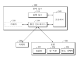
도 1은 일 실시 예에 따른 로봇 시스템이 동작하는 환경을 나타낸다.
도 2는 일 실시 예에 따른 로봇의 구성을 나타내는 블록도이다.
도 3은 일 실시 예에 따른 전자 장치의 구성을 나타내는 블록도이다.
도 4는 일 실시 예에 따른 로봇 시스템의 예시적인 동작을 나타낸다.
도 5는 일 실시 예에 따른 로봇 시스템의 예시적인 동작을 나타낸다.
도 6은 일 실시 예에 따른 로봇 시스템의 예시적인 동작을 나타낸다.
도 7은 일 실시 예에 따른 로봇 시스템의 예시적인 동작을 나타낸다.
도 8은 일 실시 예에 따른 로봇 시스템의 예시적인 동작을 나타낸다.
도 9는 일 실시 예에 따른 로봇 시스템의 예시적인 동작을 나타낸다.
도 10은 일 실시 예에 따른 로봇 시스템의 예시적인 동작을 나타낸다.
도 11은 일 실시 예에 따른 핸드-아이 캘리브레이션의 수행 방법을 설명하기 위한 흐름도이다.
도 12는 일 실시 예에 따른 핸드-아이 캘리브레이션의 수행 방법을 설명하기 위한 흐름도이다.Figure 1 shows an environment in which a robot system operates according to an embodiment.
Figure 2 is a block diagram showing the configuration of a robot according to one embodiment.
Figure 3 is a block diagram showing the configuration of an electronic device according to an embodiment.
4 shows example operations of a robotic system according to one embodiment.
5 shows example operations of a robotic system according to one embodiment.
6 shows example operations of a robotic system according to one embodiment.
7 shows example operations of a robotic system according to one embodiment.
8 shows example operations of a robotic system according to one embodiment.
9 shows example operations of a robotic system according to one embodiment.
10 shows example operations of a robot system according to one embodiment.
Figure 11 is a flowchart explaining a method of performing hand-eye calibration according to an embodiment.
Figure 12 is a flowchart explaining a method of performing hand-eye calibration according to an embodiment.
이하, 본 문서의 다양한 실시예들이 첨부된 도면을 참조하여 기재된다. 실시예 및 이에 사용된 용어들은 본 문서에 기재된 기술을 특정한 실시 형태에 대해 한정하려는 것이 아니며, 해당 실시예의 다양한 변경, 균등물, 및/또는 대체물을 포함하는 것으로 이해되어야 한다. 도면의 설명과 관련하여, 유사한 구성요소에 대해서는 유사한 참조 부호가 사용될 수 있다. 단수의 표현은 문맥상 명백하게 다르게 뜻하지 않는 한, 복수의 표현을 포함할 수 있다. 본 문서에서, "A 또는 B" 또는 "A 및/또는 B 중 적어도 하나" 등의 표현은 함께 나열된 항목들의 모든 가능한 조합을 포함할 수 있다. "제 1," "제 2," "첫째," 또는 "둘째,"등의 표현들은 해당 구성요소들을, 순서 또는 중요도에 상관없이 수식할 수 있고, 한 구성요소를 다른 구성요소와 구분하기 위해 사용될 뿐 해당 구성요소들을 한정하지 않는다. 어떤(예: 제 1) 구성요소가 다른(예: 제 2) 구성요소에 "(기능적으로 또는 통신적으로) 연결되어" 있다거나 "접속되어" 있다고 언급된 때에는, 상기 어떤 구성요소가 상기 다른 구성요소에 직접적으로 연결되거나, 다른 구성요소(예: 제 3 구성요소)를 통하여 연결될 수 있다.Hereinafter, various embodiments of this document are described with reference to the attached drawings. The examples and terms used herein are not intended to limit the technology described in this document to specific embodiments, and should be understood to include various modifications, equivalents, and/or substitutes for the examples. In connection with the description of the drawings, similar reference numbers may be used for similar components. Singular expressions may include plural expressions, unless the context clearly indicates otherwise. In this document, expressions such as “A or B” or “at least one of A and/or B” may include all possible combinations of the items listed together. Expressions such as “first,” “second,” “first,” or “second,” can modify the corresponding components regardless of order or importance, and are used to distinguish one component from another. It is only used and does not limit the corresponding components. When a component (e.g., a first) component is said to be "connected (functionally or communicatively)" or "connected" to another (e.g., second) component, it means that the component is connected to the other component. It may be connected directly to a component or may be connected through another component (e.g., a third component).
본 문서에서, "~하도록 구성된(또는 설정된)(configured to)"은 상황에 따라, 예를 들면, 하드웨어적 또는 소프트웨어적으로 "~에 적합한," "~하는 능력을 가지는," "~하도록 변경된," "~하도록 만들어진," "~를 할 수 있는," 또는 "~하도록 설계된"과 상호 호환적으로(interchangeably) 사용될 수 있다. 어떤 상황에서는, "~하도록 구성된 장치"라는 표현은, 그 장치가 다른 장치 또는 부품들과 함께 "~할 수 있는" 것을 의미할 수 있다. 예를 들면, 문구 "A, B, 및 C를 수행하도록 구성된(또는 설정된) 프로세서"는 해당 동작을 수행하기 위한 전용 프로세서(예: 임베디드 프로세서), 또는 메모리 장치에 저장된 하나 이상의 소프트웨어 프로그램들을 실행함으로써, 해당 동작들을 수행할 수 있는 범용 프로세서(예: CPU 또는 application processor)를 의미할 수 있다. In this document, “configured to” means “suitable for,” “having the ability to,” or “changed to,” depending on the situation, for example, in terms of hardware or software. ," can be used interchangeably with "made to," "capable of," or "designed to." In some contexts, the expression “a device configured to” may mean that the device is “capable of” working with other devices or components. For example, the phrase "processor configured (or set) to perform A, B, and C" refers to a processor dedicated to performing the operations (e.g., an embedded processor), or by executing one or more software programs stored on a memory device. , may refer to a general-purpose processor (e.g., CPU or application processor) capable of performing the corresponding operations.
본 문서의 다양한 실시예들에 따른 전자 장치는, 예를 들면, 스마트폰, 태블릿 PC, 이동 전화기, 영상 전화기, 전자책 리더기, 데스크탑 PC, 랩탑 PC, 넷북 컴퓨터, 워크스테이션, 서버, PDA, PMP(portable multimedia player), MP3 플레이어, 의료기기, 카메라, 또는 웨어러블 장치 중 적어도 하나를 포함할 수 있다. 웨어러블 장치는 액세서리형(예: 시계, 반지, 팔찌, 발찌, 목걸이, 안경, 콘택트 렌즈, 또는 머리 착용형 장치(head-mounted-device(HMD)), 직물 또는 의류 일체형(예: 전자 의복), 신체 부착형(예: 스킨 패드 또는 문신), 또는 생체 이식형 회로 중 적어도 하나를 포함할 수 있다. 어떤 실시예들에서, 전자 장치는, 예를 들면, 텔레비전, DVD(digital video disk) 플레이어, 오디오, 냉장고, 에어컨, 청소기, 오븐, 전자레인지, 세탁기, 공기 청정기, 셋톱 박스, 홈 오토매이션 컨트롤 패널, 보안 컨트롤 패널, 미디어 박스(예: 삼성 HomeSyncTM, 애플TVTM, 또는 구글 TVTM), 게임 콘솔(예: XboxTM, PlayStationTM), 전자 사전, 전자 키, 캠코더, 또는 전자 액자 중 적어도 하나를 포함할 수 있다.Electronic devices according to various embodiments of the present document include, for example, smartphones, tablet PCs, mobile phones, video phones, e-book readers, desktop PCs, laptop PCs, netbook computers, workstations, servers, PDAs, and PMPs. (portable multimedia player), MP3 player, medical device, camera, or wearable device. Wearable devices may be accessory (e.g., watches, rings, bracelets, anklets, necklaces, glasses, contact lenses, or head-mounted-device (HMD)), fabric or clothing-integrated (e.g., electronic clothing), The electronic device may include at least one of body attached (e.g., skin pad or tattoo) or bioimplantable circuitry. In some embodiments, the electronic device may include, for example, a television, a digital video disk (DVD) player, Audio, refrigerator, air conditioner, vacuum cleaner, oven, microwave, washing machine, air purifier, set-top box, home automation control panel, security control panel, media box (e.g. Samsung HomeSync TM , Apple TV TM , or Google TV TM ) , it may include at least one of a game console (e.g., Xbox TM , PlayStation TM ), an electronic dictionary, an electronic key, a camcorder, or an electronic picture frame.
다른 실시예에서, 전자 장치는, 각종 의료기기(예: 각종 휴대용 의료측정기기(혈당 측정기, 심박 측정기, 혈압 측정기, 또는 체온 측정기 등), MRA(magnetic resonance angiography), MRI(magnetic resonance imaging), CT(computed tomography), 촬영기, 또는 초음파기 등), 네비게이션 장치, 위성 항법 시스템(GNSS(global navigation satellite system)), EDR(event data recorder), FDR(flight data recorder), 자동차 인포테인먼트 장치, 선박용 전자 장비(예: 선박용 항법 장치, 자이로 콤파스 등), 항공 전자기기(avionics), 보안 기기, 차량용 헤드 유닛(head unit), 산업용 또는 가정용 로봇, 드론(drone), 금융 기관의 ATM, 상점의 POS(point of sales), 또는 사물 인터넷 장치 (예: 전구, 각종 센서, 스프링클러 장치, 화재 경보기, 온도조절기, 가로등, 토스터, 운동기구, 온수탱크, 히터, 보일러 등) 중 적어도 하나를 포함할 수 있다. 어떤 실시예에 따르면, 전자 장치는 가구, 건물/구조물 또는 자동차의 일부, 전자 보드(electronic board), 전자 사인 수신 장치(electronic signature receiving device), 프로젝터, 또는 각종 계측 기기(예: 수도, 전기, 가스, 또는 전파 계측 기기 등) 중 적어도 하나를 포함할 수 있다. 다양한 실시예에서, 전자 장치는 플렉서블하거나, 또는 전술한 다양한 장치들 중 둘 이상의 조합일 수 있다. 본 문서의 실시예에 따른 전자 장치는 전술한 기기들에 한정되지 않는다. 본 문서에서, 사용자라는 용어는 전자 장치를 사용하는 사람 또는 전자 장치를 사용하는 장치(예: 인공지능 전자 장치)를 지칭할 수 있다. In another embodiment, the electronic device may include various medical devices (e.g., various portable medical measurement devices (such as blood sugar monitors, heart rate monitors, blood pressure monitors, or body temperature monitors), magnetic resonance angiography (MRA), magnetic resonance imaging (MRI), CT (computed tomography), radiography, or ultrasound, etc.), navigation devices, satellite navigation systems (GNSS (global navigation satellite system)), EDR (event data recorder), FDR (flight data recorder), automobile infotainment devices, marine electronic equipment (e.g. marine navigation devices, gyro compasses, etc.), avionics, security devices, head units for vehicles, industrial or home robots, drones, ATMs at financial institutions, point-of-sale (POS) at stores. of sales), or Internet of Things devices (e.g., light bulbs, various sensors, sprinkler devices, fire alarms, thermostats, street lights, toasters, exercise equipment, hot water tanks, heaters, boilers, etc.). According to some embodiments, the electronic device may be a piece of furniture, a building/structure or a vehicle, an electronic board, an electronic signature receiving device, a projector, or various measuring devices (e.g. water, electrical, It may include at least one of gas, radio wave measuring equipment, etc.). In various embodiments, the electronic device may be flexible, or may be a combination of two or more of the various devices described above. Electronic devices according to embodiments of this document are not limited to the above-described devices. In this document, the term user may refer to a person using an electronic device or a device (e.g., an artificial intelligence electronic device) using an electronic device.
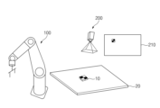
도 1은 일 실시 예에 따른 로봇 시스템이 동작하는 환경을 나타낸다.Figure 1 shows an environment in which a robot system operates according to an embodiment.
도 1을 참조하면, 일 실시 예에 따른 로봇 시스템은 로봇(100), 카메라(200) 및 전자 장치(300)를 포함할 수 있다. 로봇 시스템은, 예를 들어, 산업용 로봇(100) 시스템 또는 서비스 로봇(100) 시스템일 수 있다. 로봇(100)은 전자 장치(300) 및 카메라(200)와 무선 또는 유선으로 연결될 수 있고, 카메라(200)는 전자 장치(300)와 무선 또는 유선으로 연결될 수 있다.Referring to FIG. 1, a robot system according to an embodiment may include a
일 실시 예에 따른 로봇(100)은 복수의 조인트(joint)(111), 복수의 암 섹션(arm section)(112) 및 엔드 이펙터(end effector)(113)를 포함할 수 있다. 복수의 암 섹션(112)은 복수의 조인트(111) 중 적어도 일부에 의해 회전 가능하도록 서로 연결될 수 있다. 예를 들어, 제1 암 섹션(112a)은 제1 조인트(111a)에 의해 회전 가능하도록 제2 암 섹션(112b)과 연결될 수 있다. 제2 암 섹션(112b)은 제2 조인트(111b)에 의해 회전 가능하도록 제3 암 섹션(112c)과 연결될 수 있다. 제3 암 섹션(112c)은 제3 조인트(111c)에 의해 회전 가능하도록 엔드 이펙터(113)와 연결될 수 있다. 엔드 이펙터(113)는 외부 물체를 파지(grasp)할 수 있도록 구성될 수 있다. 제1 조인트(111a), 제2 조인트(111b) 및 제3 조인트(111c)는 각각 독립적으로 구동될 수 있다.The
일 실시 예에 따르면, 로봇(100)은 외부 물체를 파지할 수 있다. 예를 들어, 로봇(100)은 파지된 외부 물체를 로봇(100)의 기저 좌표계 {B} 내의 좌표 (Bx, By, Bz)에 대응하는 위치로 이동시킬 수 있다. 다른 예를 들면, 로봇(100)은 로봇(100)의 기저 좌표계 {B} 내의 좌표 (Bx, By, Bz)에 위치된 외부 물체를 파지할 수 있다. 로봇(100)은 로봇(100)의 기저 좌표계 {B}와 엔드 이펙터(113)의 좌표계 {H} 사이의 관계를 알 수 있다.According to one embodiment, the
일 실시 예에 따르면, 카메라(200)는 이미지를 획득할 수 있다. 예를 들어, 카메라(200)는 작업대에 대한 영상을 촬영하도록 배치될 수 있고, 작업대 상의 외부 물체에 대한 이미지를 획득할 수 있다. 카메라(200)는 획득된 이미지를 로봇(100) 또는 전자 장치(300)로 전달할 수 있다.According to one embodiment, the
일 실시 예에 따르면, 전자 장치(300)는 로봇(100) 및 카메라(200)를 제어할 수 있다. 예를 들어, 전자 장치(300)는 로봇(100)의 움직임을 제어할 수도 있고, 카메라(200)의 촬영을 제어할 수도 있다. 일 실시 예에 따르면, 로봇(100) 및 카메라(200)는 독립적으로 동작할 수도 있다. 전자 장치(300) 또는 로봇(100)은 카메라(200)에 의해 획득된 이미지를 분석함으로써 카메라(200)의 좌표계 {C} 내의 좌표 (Cx, Cy, Cz)를 획득할 수 있다. 전자 장치(300) 또는 로봇(100)은 로봇(100)의 기저 좌표계 {B} 내의 좌표 (Bx, By, Bz) 및 카메라(200)의 좌표계 {C} 내의 좌표 (Cx, Cy, Cz)에 기초하여 엔드 이펙터(113)의 좌표계 {H}와 카메라(200)의 좌표계 {C} 사이의 관계를 산출함으로써 핸드-아이 캘리브레이션을 수행할 수 있다.According to one embodiment, the
도 1에서는 로봇(100), 카메라(200) 및 전자 장치(300)가 개별적으로 구현된 것으로 도시되었으나, 이에 제한되지 않고, 로봇(100), 카메라(200) 및 전자 장치(300) 중 적어도 일부는 통합적으로 구현될 수 있다. 예를 들어, 카메라(200)는 로봇(100) 또는 전자 장치(300)에 포함될 수 있고, 전자 장치(300)는 로봇(100)에 포함될 수도 있다.In FIG. 1, the
이하에서는 도 2를 참조하여 전자 장치(300)의 제어 없이 독립적으로 동작할 수 있는 로봇(100)에 대해 설명한다.Hereinafter, the
도 2는 일 실시 예에 따른 로봇(100)의 구성을 나타내는 블록도이다.Figure 2 is a block diagram showing the configuration of the
도 2를 참조하면, 일 실시 예에 따른 로봇(100)은 로봇 암(110), 입력 장치(120), 통신 인터페이스(130) 및 제어 회로(150)를 포함할 수 있다.Referring to FIG. 2, the
로봇 암(110)은 조인트(111), 암 섹션(112) 및 엔드 이펙터(113)를 포함할 수 있다. 로봇 암(110)은 외부 물체를 파지할 수 있고, 파지된 외부 물체를 이동시킬 수 있다. 도 1을 참조하여 설명된 조인트(111), 암 섹션(112) 및 엔드 이펙터(113)에 대한 중복 설명은 생략한다.The
입력 장치(120)는 로봇(100)의 사용자로부터 입력을 수신할 수 있다. 입력 장치(120)는, 예를 들어, 하나 이상의 키, 키보드, 마우스 또는 터치 패널 등과 같은 다양한 장치 중 하나일 수 있다. 일 실시 예에 따르면, 입력 장치(120)는 로봇(100)의 사용자로부터 핸드-아이 캘리브레이션을 개시하는 명령을 수신할 수 있다.The
통신 인터페이스(130)는 카메라(200)와 무선 또는 유선으로 연결될 수 있다. 예를 들어, 통신 인터페이스(130)는 카메라(200)와 무선으로 통신하는 무선 통신 회로일 수 있다. 다른 예를 들면, 통신 인터페이스(130)는 카메라(200)와 유선으로 연결된 인터페이스일 수 있다.The
일 실시 예에 따르면, 로봇(100)은 카메라(140)를 더 포함할 수 있다. 로봇(100)이 카메라(140)를 포함하는 경우, 통신 인터페이스(130)는 카메라(140)와 제어 회로(150)를 연결하는 인터페이스일 수 있고, 제어 회로(150)는 카메라(140)로부터 이미지를 획득할 수 있다. 이하에서는 설명의 편의를 위해 로봇(100)이 외부의 카메라(200)와 연결된 것으로 가정한다.According to one embodiment, the
제어 회로(150)는 로봇 암(110), 입력 장치(120) 및 통신 인터페이스(130)와 전기적으로 연결될 수 있다. 제어 회로(150)는 로봇 암(110), 입력 장치(120) 및 통신 인터페이스(130) 중 적어도 일부를 제어할 수 있다.The
일 실시 예에 따르면, 외부 물체는 사용자에 의해 외부 물체의 중심이 엔드 이펙터(113)의 중심과 일치하도록 엔드 이펙터(113)에 고정될 수 있다. According to one embodiment, an external object may be fixed to the
일 실시 예에 따르면, 제어 회로(150)는 엔드 이펙터(113)를 이용하여 외부 물체를 파지할 수 있다. 예를 들어, 제어 회로(150)는 외부 물체가 지정된 좌표에 대응하는 위치에 놓인 경우, 엔드 이펙터(113)를 지정된 좌표로 이동시킨 후 외부 물체를 파지할 수 있다. 제어 회로(150)는 엔드 이펙터(113)의 중심이 외부 물체의 중심과 일치하도록 엔드 이펙터(113)를 이용하여 외부 물체를 파지할 수 있다.According to one embodiment, the
일 실시 예에 따르면, 제어 회로(150)는 엔드 이펙터(113)의 중심이 외부 물체의 중심과 일치하도록 외부 물체가 엔드 이펙터(113)에 의해 파지된 후, 외부 물체를 작업대 상에 배치하도록 로봇 암(110)을 제어할 수 있다. 예를 들어, 제어 회로(150)는 외부 물체를 지정된 작업대 상의 임의의 위치에 배치하도록 로봇 암(110)을 제어할 수 있다. 제어 회로(150)는, 예를 들어, 외부 물체를 로봇(100)의 기저 좌표계 {B} 내의 좌표 (Bx1, By1, Bz1)에 대응하는 위치에 배치하도록 로봇 암(110)을 제어할 수 있다.According to one embodiment, the
일 실시 예에 따르면, 제어 회로(150)는 카메라(200)에 의해 촬영된 외부 물체에 대한 영상으로부터 카메라(200)의 좌표계 내의 외부 물체의 중심점의 좌표를 획득할 수 있다. 제어 회로(150)는 카메라(200)(또는 카메라(140))로부터 외부 물체에 대한 영상을 획득할 수 있다. 제어 회로(150)는 획득된 영상을 분석함으로써, 예를 들어, 카메라(200)의 좌표계 {C} 내의 외부 물체의 중심점의 좌표 (u1, v1)을 획득할 수 있다.According to one embodiment, the
일 실시 예에 따르면, 제어 회로(150)는 작업대 상의 다양한 위치에 배치된 외부 물체의 좌표를 획득할 수 있다. 제어 회로(150)는 좌표 (Bx1, By1, Bz1) 및 좌표 (u1, v1)이 획득된 후, 외부 물체를 다른 위치에 배치할 수 있다. 제어 회로(150)는, 예를 들어, 다른 위치에 배치된 외부 물체에 대응하는 좌표 (Bx2, By2, Bz2) 및 좌표 (u2, v2)를 획득할 수 있다. 제어 회로(150)는 좌표 (Bx2, By2, Bz2) 및 좌표 (u2, v2)가 획득된 후, 외부 물체를 또 다른 위치에 배치할 수 있다. 제어 회로(150)는, 예를 들어, 또 다른 위치에 배치된 외부 물체에 대응하는 좌표 (Bx3, By3, Bz3) 및 좌표 (u3, v3)를 획득할 수 있다. 제어 회로(150)는 상술한 동작을 목표된 개수의 좌표(예: 4개)가 획득될 때까지 반복할 수 있다.According to one embodiment, the
일 실시 예에 따르면, 제어 회로(150)는 외부 물체가 작업대 상에 배치될 때 로봇(100)의 기저 좌표계 내의 엔드 이펙터(113)의 좌표 및 카메라(200)의 좌표계 내의 외부 물체의 중심점의 좌표에 기초하여 엔드 이펙터(113)의 좌표계 {H}와 카메라(200)의 좌표계 {C} 사이의 관계를 정의하는 캘리브레이션 파라미터를 산출할 수 있다. 예를 들어, 제어 회로(150)는 로봇(100)의 기저 좌표계 {B} 내의 좌표 (Bx1, By1, Bz1), (Bx2, By2, Bz2) 및 (Bx3, By3, Bz3), 및 카메라(200)의 좌표계 {C} 내의 좌표 (u1, v1), (u2, v2) 및 (u3, v3) 등에 기초하여 캘리브레이션 파라미터를 산출할 수 있다. 캘리브레이션 파라미터는, 예를 들어, 엔드 이펙터(113)의 좌표계 {H}와 카메라(200)의 좌표계 {C} 사이의 관계를 정의하는 병진 벡터(Translation Vector) 및 회전 행렬(Rotation Matrix)을 포함할 수 있다.According to one embodiment, when an external object is placed on a workbench, the
일 실시 예에 따르면, 제어 회로(150)는 로봇(100)의 기저 좌표계 {B}와 카메라(200)의 좌표계 {C} 사이의 관계를 정의하는 제1 파라미터, 및 로봇(100)의 기저 좌표계 {B}와 엔드 이펙터(113)의 좌표계 {H} 사이의 관계를 정의하는 제2 파라미터에 기초하여 캘리브레이션 파라미터를 산출할 수 있다. 예를 들어, 제어 회로(150)는 좌표 (Bx1, By1, Bz1), (Bx2, By2, Bz2) 및 (Bx3, By3, Bz3), (u1, v1), (u2, v2) 및 (u3, v3) 등에 기초하여 기저 좌표계 {B}와 카메라(200) 좌표계 {C} 사이의 좌표 변환 관계를 정의하는 제1 병진 벡터 및 제1 회전 행렬을 산출할 수 있다. 로봇(100)의 기저 좌표계 {B}와 엔드 이펙터(113)의 좌표계 {H} 사이의 좌표 변환 관계를 정의하는 제2 병진 벡터 및 제2 회전 행렬은 로봇(100)에 미리 저장될 수도 있고, 로봇(100) 운동학(Robot Kinematics)에 기초하여 산출될 수도 있다. 제어 회로(150)는 제1 병진 벡터, 제1 회전 행렬, 제2 병진 벡터 및 제2 회전 행렬에 기초하여 캘리브레이션 파라미터를 산출할 수 있다.According to one embodiment, the
일 실시 예에 따르면, 캘리브레이션 파라미터는 사영 변환(projective transformation)과 연관된 호모그래피 행렬(homography matrix)을 포함할 수 있다. 예를 들어, 작업대의 z 좌표가 로봇(100)에 미리 저장된 경우, 제어 회로(150)는 좌표 (Bx1, By1), (Bx2, By2), (Bx3, By3), (u1, v1), (u2, v2) 및 (u3, v3) 등에 기초하여 호모그래피 행렬을 산출할 수 있다.According to one embodiment, the calibration parameter may include a homography matrix associated with a projective transformation. For example, if the z coordinate of the workbench is pre-stored in the
일 실시 예에 따르면, 캘리브레이션 파리미터는 카메라(200) 고유 파라미터(camera intrinsic parameter)를 포함할 수도 있다. 제어 회로(150)는 카메라(200)에 의해 획득된 영상을 분석함으로써, 카메라(200)의 초점 거리 및/또는 렌즈 왜곡 계수를 포함하는 카메라(200) 고유 파라미터를 산출할 수 있다.According to one embodiment, the calibration parameters may include camera intrinsic parameters. The
제어 회로(150)는 Zhengyou Zhang이 제안한 방법(A flexible new technique for camera calibration. IEEE Transactions on Pattern Analysis and Machine Intelligence, 22(11):1330-1334, 2000)을 적용함으로써, 상술한 파라미터 중 적어도 일부를 산출할 수 있다.The
이하에서는 도 3을 참조하여 로봇(100)을 제어할 수 있는 전자 장치(300)에 대해 설명한다.Hereinafter, the
도 3은 일 실시 예에 따른 전자 장치(300)의 구성을 나타내는 블록도이다.FIG. 3 is a block diagram showing the configuration of an
도 3을 참조하면, 일 실시 예에 따른 전자 장치(300)는 입력 장치(310), 통신 인터페이스(320) 및 프로세서(340)를 포함할 수 있다. 전자 장치(300)는 로봇(100) 및 카메라(200)를 제어할 수 있는 다양한 종류의 컴퓨팅 디바이스 중 하나일 수 있다.Referring to FIG. 3 , the
입력 장치(310)는 로봇(100)의 사용자로부터 입력을 수신할 수 있다. 입력 장치(310)는, 예를 들어, 하나 이상의 키, 키보드, 마우스 또는 터치 패널 등과 같은 다양한 장치 중 하나일 수 있다. 일 실시 예에 따르면, 입력 장치(310)는 로봇(100)의 사용자로부터 핸드-아이 캘리브레이션을 개시하는 명령을 수신할 수 있다.The
통신 인터페이스(320)는 카메라(200) 및 로봇(100)과 무선 또는 유선으로 연결될 수 있다. 예를 들어, 통신 인터페이스(320)는 카메라(200) 및/또는 로봇(100)과 무선으로 통신하는 무선 통신 회로일 수 있다. 다른 예를 들면, 통신 인터페이스(320)는 카메라(200) 및/또는 로봇(100)과 유선으로 연결된 인터페이스일 수 있다. 도 3에서는 전자 장치(300)가 하나의 통신 인터페이스(320)를 포함하는 것으로 도시되었으나, 이에 제한되지 않고, 전자 장치(300)는 카메라(200)와 연결된 제1 통신 인터페이스(320) 및 로봇(100)과 연결된 제2 통신 인터페이스(320)를 포함할 수도 있다.The
일 실시 예에 따르면, 전자 장치(300)는 카메라(330)를 더 포함할 수 있다. 전자 장치(300)가 카메라(330)를 포함하는 경우, 통신 인터페이스(320)는 카메라(330)와 제어 회로를 연결하는 인터페이스일 수 있고, 제어 회로는 카메라(330)로부터 이미지를 획득할 수 있다.According to one embodiment, the
프로세서(340)는 입력 장치(310) 및 통신 인터페이스(320)와 전기적으로 연결될 수 있다. 프로세서(340)는 입력 장치(310) 및 통신 인터페이스(320) 중 적어도 일부를 제어할 수 있다. 프로세서(340)는 통신 인터페이스(320)를 통해 카메라(200) 및 로봇(100)을 제어할 수 있다. 프로세서(340)는 도 2의 제어 회로(150)와 유사한 동작을 수행할 수 있고, 카메라(200) 및 로봇(100)을 제어함으로써, 엔드 이펙터(113)의 좌표계 {H}와 카메라(200)의 좌표계{C} 사이의 관계를 정의하는 캘리브레이션 파라미터를 산출할 수 있다.The
이하에서는 도 4 내지 도 10을 참조하여 일 실시 예에 따른 로봇(100) 및 카메라(200)의 예시적인 동작들에 대해 설명한다. 도 4 내지 도 10을 참조하여 설명되는 동작들은 도 2의 로봇(100) 또는 도 3의 전자 장치(300)에 의해 수행되는 것으로 이해될 수 있다. 설명의 편의를 위해 이하에서는 도 4 내지 도 10의 동작들이 도 2의 로봇(100)에 의해 수행되는 것으로 설명한다.Hereinafter, exemplary operations of the
도 4는 일 실시 예에 따른 로봇 시스템의 예시적인 동작을 나타낸다.4 shows example operations of a robotic system according to one embodiment.
도 4를 참조하면, 로봇(100)은 엔드 이펙터(113)를 이용하여 외부 물체(10)를 파지할 수 있다. 외부 물체(10)는 외부 물체(10)의 중심이 엔드 이펙터(113)의 중심과 일치하도록 엔드 이펙터(113)에 파지될 수 있다. 외부 물체(10)는 중심을 식별할 수 있는 패턴 또는 형상으로 이루질 수 있다. 외부 물체(10)는, 예를 들어, 도 4에 도시된 바와 같이 격자 패턴을 포함할 수 있다. 예를 들어, 외부 물체(10)는 로봇(100)의 사용자에 의해 엔드 이펙터(113)에 파지될 수 있다.Referring to FIG. 4 , the
일 실시 예에 따르면, 로봇(100)은 외부 물체(10)가 작업대의 지정된 위치에 배치되면, 엔드 이펙터(113)의 중심이 외부 물체(10)의 중심과 일치하도록 외부 물체(10)를 파지하기 위해 로봇 암을 제어할 수도 있다. 예를 들어, 사용자가 지정된 위치에 외부 물체(10)를 놓은 후, 핸드-아이 캘리브레이션을 개시하도록 로봇(100)을 제어하면, 로봇(100)은 엔드 이펙터(113)의 중심이 외부 물체(10)의 중심과 일치하도록 엔드 이펙터(113)를 이용하여 지정된 위치에 배치된 외부 물체(10)를 파지할 수 있다.According to one embodiment, when the
도 5는 일 실시 예에 따른 로봇 시스템의 예시적인 동작을 나타낸다. 도 6은 일 실시 예에 따른 로봇 시스템의 예시적인 동작을 나타낸다.5 shows example operations of a robotic system according to one embodiment. 6 shows example operations of a robotic system according to one embodiment.
도 5 및 도 6을 참조하면, 로봇(100)은 엔드 이펙터의 중심이 외부 물체(10)의 중심과 일치하도록 외부 물체(10)가 엔드 이펙터에 파지된 후, 외부 물체(10)를 작업대(20) 상에 배치하도록 로봇 암을 제어할 수 있다. 예를 들어, 로봇(100)은 외부 물체(10)가 엔드 이펙터에 파지된 후, 입력 장치를 통해 로봇(100)의 사용자의 명령이 입력되면, 외부 물체(10)를 작업대(20)에 배치할 수 있다. 로봇(100)은 로봇(100)의 기저 좌표계 {B} 내의 좌표 (Bx1, By1, Bz1)에 대응하는 작업대(20) 상의 위치에 외부 물체(10)를 배치할 수 있다. 로봇(100)은 로봇(100) 운동학에 기초하여 좌표 (Bx1, By1, Bz1)를 엔드 이펙터의 좌표계 {H} 내의 좌표로 재정의 할 수 있다. 로봇(100)의 기저 좌표계 {B}의 x-y 평면과 작업대(20)는 서로 평행할 수 있고, 좌표계 {B}의 x-y 평면과 작업대(20) 사이의 거리는 로봇(100)에 알려질 수 있다.5 and 6, the
도 7은 일 실시 예에 따른 로봇 시스템의 예시적인 동작을 나타낸다.7 shows example operations of a robotic system according to one embodiment.
도 7을 참조하면, 로봇(100)은 카메라(200)에 의해 외부 물체(10)에 대한 영상(210)이 촬영되기 전에, 로봇 암이 카메라(200)의 시야 밖으로 이동되도록 로봇 암을 제어할 수 있다. 로봇(100)은 카메라(200)가 영상(210)을 촬영할 때, 로봇 암에 의해 외부 물체(10)가 가려지지 않도록 로봇 암을 카메라(200)의 시야 밖으로 이동시킬 수 있다.Referring to FIG. 7, the
카메라(200)는 로봇 암이 카메라(200)의 시야 밖으로 이동된 후 외부 물체(10)에 대한 영상(210)을 획득할 수 있다. 카메라(200)는 작업대(20)를 향하도록 배치될 수 있다. 카메라(200)는 획득된 영상(210)을 저장할 수 있다. 카메라(200)에 의해 획득된 영상(210)은 로봇(100)으로 전달될 수 있다. 카메라(200)에 의해 획득된 영상(210)은 도 3의 전자 장치(300)로 전달될 수도 있다.The
도 8은 일 실시 예에 따른 로봇 시스템의 예시적인 동작을 나타낸다.8 shows example operations of a robotic system according to one embodiment.
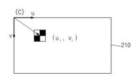
도 8을 참조하면, 로봇(100)은 외부 물체(10)의 패턴을 이용하여 외부 물체(10)에 대한 영상(210)을 분석함으로써 카메라(200)의 좌표계 {C} 내의 외부 물체(10)의 중심점의 좌표 (u1, v1)을 획득할 수 있다. 예를 들어, 로봇(100)은 카메라(200)에 의해 획득된 외부 물체(10)에 대한 영상(210)을 분석할 수 있다. 로봇(100)은 영상(210)을 분석함으로써 외부 물체(10)에 포함된 격자 패턴을 인식할 수 있다. 로봇(100)은 외부 물체(10)의 패턴을 이용하여 카메라(200)의 좌표계 {C} 내의 외부 물체(10)의 중심점의 좌표 (u1, v1)을 획득할 수 있다. 도 8에 도시되지는 않았으나, 로봇(100)은 외부 물체(10)의 형상을 이용하여 외부 물체(10)에 대한 영상(210)을 분석함으로써 카메라(200)의 좌표계 {C} 내의 외부 물체(10)의 중심점의 좌표를 획득할 수도 있다.Referring to FIG. 8, the
도 9는 일 실시 예에 따른 로봇 시스템의 예시적인 동작을 나타낸다.9 shows example operations of a robotic system according to one embodiment.
도 9를 참조하면, 로봇(100)은 영상(210)이 촬영된 후 작업대(20) 상의 외부 물체(10)를 파지할 수 있다. 로봇(100)은 로봇(100)의 기저 좌표계 {B} 내의 좌표 (Bx1, By1, Bz1)에 대응하는 위치로 엔드 이펙터(113)를 이동시키고, 엔드 이펙터(113)를 이용하여 외부 물체(10)를 파지할 수 있다. 로봇(100)은 외부 물체(10)를 파지한 후, 도 10에 도시된 바와 같이, 외부 물체(10)를 작업대(20) 상의 다른 위치로 이동시킬 수 있다.Referring to FIG. 9 , the
도 10은 일 실시 예에 따른 로봇 시스템의 예시적인 동작을 나타낸다.10 shows example operations of a robot system according to one embodiment.
도 10을 참조하면, 로봇(100)은 도 4 내지 도 9에 도시된 동작을 반복할 수 있다. 예를 들어, 로봇(100)은 좌표 (Bx1, By1, Bz1)에 대응하는 위치에 놓인 외부 물체(10)를 파지한 후, 외부 물체(10)를 다른 위치, 예를 들어, 좌표 (Bx2, By2, Bz2)에 대응하는 위치로 이동시킬 수 있다. 로봇(100)은 외부 물체(10)를 좌표 (Bx2, By2, Bz2)에 대응하는 위치로 이동시킨 후, 로봇 암에 의해 외부 물체(10)가 가려지지 않도록 로봇 암을 카메라(200)의 시야 밖으로 이동시킬 수 있다. 카메라(200)는 로봇 암이 시야 밖으로 이동된 후 외부 물체(10)에 대한 영상(220)을 획득할 수 있다. 로봇(100)은 영상(220)을 분석함으로써 카메라(200)의 좌표계 {C} 내의 외부 물체(10)의 중심점의 좌표 (u2, v2)를 획득할 수 있다. 로봇(100)은 영상(220)이 촬영된 후, 좌표 (Bx2, By2, Bz2)에 대응하는 위치로 엔드 이펙터(113)를 이동시키고, 엔드 이펙터(113)를 이용하여 외부 물체(10)를 파지할 수 있다. 로봇(100)은 외부 물체(10)를 파지한 후, 다시 외부 물체(10)를 작업대(20) 상의 또 다른 위치(예: 좌표 (Bx3, By3, Bz3))로 이동시킬 수 있다.Referring to FIG. 10, the
로봇(100)은, 예를 들어, 적어도 4쌍 이상의 좌표를 획득할 수 있다. 로봇(100)은 획득된 4쌍 이상의 좌표에 기초하여 캘리브레이션 파라미터를 산출할 수 있다. 획득된 좌표의 개수가 많을수록 핸드-아이 캘리브레이션의 정확도는 향상될 수 있다. For example, the
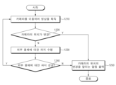
도 11은 일 실시 예에 따른 핸드-아이 캘리브레이션의 수행 방법을 설명하기 위한 흐름도이다.Figure 11 is a flowchart explaining a method of performing hand-eye calibration according to an embodiment.
이하에서는 도 2의 로봇(100) 또는 도 3의 전자 장치(300)가 도 11의 프로세스를 수행하는 것을 가정한다. 또한, 도 11의 동작들은 도 2의 로봇(100)의 제어 회로(150) 또는 도 3의 전자 장치(300)의 프로세서(340)에 의해 수행되는 것으로 이해될 수 있다. 설명의 편의를 위해 이하에서는 도 11의 동작들이 도 2의 로봇(100)에 의해 수행되는 것으로 설명한다.Hereinafter, it is assumed that the
도 11을 참조하면, 동작 1110에서, 로봇은 외부 물체를 작업대 상에 배치하도록 로봇 암을 제어할 수 있다. 예를 들어, 로봇은 외부 물체를 작업대 상의 제1 위치에 배치하도록 로봇 암을 제어할 수 있다.Referring to FIG. 11 , in
동작 1120에서, 로봇은 로봇 암이 카메라의 시야 밖으로 이동하도록 로봇 암을 제어할 수 있다. 예를 들어, 로봇은 카메라가 외부 물체에 대한 영상을 촬영하기 전에, 로봇 암에 의해 카메라의 시야가 가려지지 않도록, 로봇 암을 카메라의 시야 밖으로 이동시킬 수 있다.At
동작 1130에서, 로봇은 카메라에 의해 촬영된 외부 물체에 대한 영상을 획득할 수 있다. 예를 들어, 로봇은 카메라가 제1 위치에 배치된 외부 물체에 대한 영상을 촬영하면, 카메라로부터 제1 위치에 배치된 외부 물체에 대한 영상을 수신할 수 있다.In
동작 1140에서, 로봇은 영상으로부터 카메라의 좌표계 내의 외부 물체의 중심점의 좌표를 획득할 수 있다. 예를 들어, 로봇은 획득된 영상에 포함된 외부 물체의 패턴 또는 형상을 분석함으로써 외부 물체의 중심점의 좌표를 획득할 수 있다.In
동작 1150에서, 로봇은 지정된 개수의 좌표가 획득되었는지 여부를 판단할 수 있다. 예를 들어, 로봇은 적어도 4개 이상의 미리 설정된 개수의 좌표가 획득되었는지 여부를 판단할 수 있다. 지정된 개수의 좌표가 획득되기 전까지 로봇은 동작 1110 내지 동작 1140을 반복할 수 있다. 로봇은 외부 물체를 제2 위치, 제3 위치 및 제4 위치 등에 배치하고, 제2 위치, 제3 위치 및 제4 위치 등에 대한 좌표를 반복적으로 획득할 수 있다.In
지정된 개수의 좌표가 획득되면, 동작 1160에서, 로봇은 엔드 이펙터의 좌표 및 외부 물체의 중심점의 좌표에 기초하여 캘리브레이션 파라미터를 산출할 수 있다. 예를 들어, 로봇은 외부 물체를 배치할 때 엔드 이펙터의 좌표계 내의 좌표들 및 영상을 분석함으로써 획득된 외부 물체의 중심점의 좌표들에 기초하여 병진 벡터 및 회전 행렬 등을 포함하는 캘리브레이션 파라미터를 산출할 수 있다.When the designated number of coordinates is obtained, in
도 12는 일 실시 예에 따른 핸드-아이 캘리브레이션의 수행 방법을 설명하기 위한 흐름도이다.Figure 12 is a flowchart explaining a method of performing hand-eye calibration according to an embodiment.
이하에서는 도 2의 로봇(100) 또는 도 3의 전자 장치(300)가 도 11의 프로세스를 수행하는 것을 가정한다. 또한, 도 11의 동작들은 도 2의 로봇(100)의 제어 회로(150) 또는 도 3의 전자 장치(300)의 프로세서(340)에 의해 수행되는 것으로 이해될 수 있다. 설명의 편의를 위해 이하에서는 도 11의 동작들이 도 2의 로봇(100)에 의해 수행되는 것으로 설명한다.Hereinafter, it is assumed that the
도 12를 참조하면, 동작 1210에서, 로봇은 카메라를 이용하여 영상을 획득할 수 있다. 예를 들어, 로봇은 카메라를 이용하여 지속적으로 작업대에 대한 복수의 영상을 획득할 수 있다.Referring to FIG. 12, in operation 1210, the robot may acquire an image using a camera. For example, the robot can continuously acquire multiple images of the workbench using a camera.
동작 1220에서, 로봇은 카메라의 위치가 변경되었는지 여부를 판단할 수 있다. 예를 들어, 로봇은 카메라에 의해 획득된 2 이상의 영상을 비교할 수 있다. 로봇은 제1 영상과 제2 영상의 전체 영역에서 픽셀의 밝기가 상이한 경우, 카메라의 위치가 변경된 것으로 판단할 수 있다.In
카메라의 위치가 변경되지 않은 것으로 판단되면, 동작 1230에서, 로봇은 외부 물체에 대한 파지를 수행할 수 있다. 예를 들어, 로봇은 로봇에 저장된 좌표에 기초하여 외부 물체에 대한 파지를 수행할 수 있다. 로봇은 외부 물체를 파지한 후 외부 물체를 이동시킬 수 있다.If it is determined that the position of the camera has not changed, in
동작 1240에서, 로봇은 외부 물체에 대한 파지가 성공되었는지 여부를 판단할 수 있다. 예를 들어, 로봇은 외부 물체를 파지하기 전에 획득된 영상과 외부 물체를 파지한 후 획득된 영상을 비교할 수 있다. 로봇은 외부 물체를 파지하기 전에 획득된 영상과 외부 물체를 파지한 후 획득된 영상의 외부 물체가 있던 영역에서 픽셀의 밝기가 상이한 경우, 외부 물체에 대한 파지가 성공된 것으로 판단할 수 있다. 외부 물체의 파지가 성공되면, 로봇은 동작 1210을 다시 수행할 수 있다.In
카메라의 위치가 변경되거나, 외부 물체의 파지가 실패한 경우, 동작 1250에서, 로봇은 카메라의 위치의 변경을 알리는 알림을 출력할 수 있다. 예를 들어, 로봇은 카메라의 위치가 변경되거나, 외부 물체의 파지가 실패하면, 카메라의 위치가 변경된 것으로 판단하고, 사용자에게 카메라의 위치가 변경되었음을 알리기 위해 알림을 출력할 수 있다. 로봇은, 예를 들어, 소리 알림을 출력할 수도 있고 로봇(또는 전자 장치)에 포함되거나 로봇과 연결된 디스플레이에 메시지를 출력할 수도 있다. 로봇은 알림을 출력한 후, 도 11을 참조하여 설명된 핸드-아이 캘리브레이션을 다시 수행할 수 있다.If the position of the camera changes or the grip of the external object fails, in
일 실시 예에 따른 핸드-아이 캘리브레이션을 수행하는 로봇은 복수의 조인트(joint), 복수의 조인트 중 적어도 일부에 의해 회전 가능하도록 서로 연결된 복수의 암 섹션(arm section), 및 복수의 조인트 중 하나와 연결되고 외부 물체를 파지(grasp)할 수 있도록 구성된 엔드 이펙터(end effector)를 포함하는 로봇 암(robot arm), 카메라와 무선 또는 유선으로 연결된 통신 인터페이스 및 로봇 암 및 통신 인터페이스와 전기적으로 연결된 제어 회로를 포함하고, 제어 회로는, 엔드 이펙터의 중심이 외부 물체의 중심과 일치하도록 외부 물체가 엔드 이펙터에 의해 파지된 후, 외부 물체를 작업대 상에 배치하도록 로봇 암을 제어하고, 카메라에 의해 촬영된 외부 물체에 대한 영상으로부터 카메라의 좌표계 내의 외부 물체의 중심점의 좌표를 획득하고, 외부 물체가 작업대 상에 배치될 때 로봇의 기저 좌표계 내의 엔드 이펙터의 좌표 및 카메라의 좌표계 내의 외부 물체의 중심점의 좌표에 기초하여 엔드 이펙터의 좌표계와 카메라의 좌표계 사이의 관계를 정의하는 캘리브레이션 파라미터를 산출할 수 있다.A robot that performs hand-eye calibration according to an embodiment includes a plurality of joints, a plurality of arm sections rotatably connected to each other by at least some of the plurality of joints, and one of the plurality of joints. A robot arm including an end effector connected and configured to grasp an external object, a communication interface connected wirelessly or wired to a camera, and a control circuit electrically connected to the robot arm and the communication interface. A control circuit controls the robot arm to place the external object on the workbench after the external object is gripped by the end effector so that the center of the end effector coincides with the center of the external object, and the image taken by the camera is Obtain the coordinates of the center point of the external object in the camera's coordinate system from the image of the external object, and when the external object is placed on the workbench, the coordinates of the end effector in the robot's base coordinate system and the coordinates of the center point of the external object in the camera's coordinate system are Based on this, calibration parameters that define the relationship between the coordinate system of the end effector and the coordinate system of the camera can be calculated.
일 실시 예에 따르면, 로봇은 카메라를 더 포함하고, 통신 인터페이스는 카메라와 제어 회로를 연결하는 인터페이스일 수 있다.According to one embodiment, the robot further includes a camera, and the communication interface may be an interface that connects the camera and the control circuit.
일 실시 예에 따르면, 통신 인터페이스는 카메라와 통신하는 무선 통신 회로일 수 있다.According to one embodiment, the communication interface may be a wireless communication circuit that communicates with the camera.
일 실시 예에 따르면, 제어 회로는, 외부 물체가 작업대의 지정된 위치에 배치되면, 엔드 이펙터의 중심이 외부 물체의 중심과 일치하도록 외부 물체를 파지하기 위해 로봇 암을 제어할 수 있다.According to one embodiment, the control circuit may control the robot arm to grip the external object so that the center of the end effector coincides with the center of the external object when the external object is placed at a designated location on the workbench.
일 실시 예에 따르면, 로봇은 제어 회로와 전기적으로 연결되고, 로봇의 사용자로부터 입력을 수신하는 입력 장치를 더 포함하고, 제어 회로는, 엔드 이펙터의 중심이 외부 물체의 중심과 일치하도록 외부 물체가 엔드 이펙터에 파지된 후, 입력 장치를 통해 로봇의 사용자의 명령이 입력되면, 외부 물체를 작업대 상에 배치하도록 로봇 암을 제어할 수 있다.According to one embodiment, the robot is electrically connected to a control circuit and further includes an input device for receiving an input from a user of the robot, wherein the control circuit is configured to cause the external object to be moved such that the center of the end effector coincides with the center of the external object. After being gripped by the end effector, when the robot user's command is input through the input device, the robot arm can be controlled to place the external object on the workbench.
일 실시 예에 따르면, 제어 회로는, 카메라에 의해 외부 물체에 대한 영상이 촬영되기 전에, 로봇 암이 카메라의 시야 밖으로 이동되도록 로봇 암을 제어 할 수 있다.According to one embodiment, the control circuit may control the robot arm to move the robot arm out of the camera's field of view before an image of an external object is captured by the camera.
일 실시 예에 따르면, 제어 회로는, 외부 물체의 패턴을 이용하여 외부 물체에 대한 영상을 분석함으로써 카메라의 좌표계 내의 외부 물체의 중심점의 좌표를 획득할 수 있다.According to one embodiment, the control circuit may acquire the coordinates of the center point of the external object within the coordinate system of the camera by analyzing the image of the external object using the pattern of the external object.
일 실시 예에 따르면, 제어 회로는, 엔드 이펙터의 중심이 외부 물체의 중심과 일치하도록 외부 물체가 엔드 이펙터에 의해 파지된 후, 외부 물체를 작업대의 제1 위치 상에 배치하도록 로봇 암을 제어하고, 외부 물체가 제1 위치 상에 배치될 때 로봇의 기저 좌표계 내의 엔드 이펙터의 제1 좌표를 획득하고, 카메라에 의해 촬영된 외부 물체에 대한 제1 영상으로부터 카메라의 좌표계 내의 외부 물체의 중심점의 제1 좌표를 획득하고, 제1 위치에 배치된 외부 물체를 파지하고, 외부 물체를 작업대의 제1 위치와 상이한 제2 위치 상에 배치하도록 로봇 암을 제어하고, 외부 물체가 제2 위치 상에 배치될 때 로봇의 기저 좌표계 내의 엔드 이펙터의 제2 좌표를 획득하고, 카메라에 의해 촬영된 외부 물체에 대한 제2 영상으로부터 카메라의 좌표계 내의 외부 물체의 중심점의 제2 좌표를 획득하고, 엔드 이펙터의 제1 좌표, 외부 물체의 중심점의 제1 좌표, 엔드 이펙터의 제2 좌표 및 외부 물체의 중심점의 제2 좌표에 기초하여 엔드 이펙터의 좌표계와 카메라의 좌표계 사이의 관계를 정의하는 캘리브레이션 파라미터를 산출할 수 있다.According to one embodiment, the control circuit controls the robot arm to place the foreign object on the first position of the workbench after the foreign object is gripped by the end effector such that the center of the end effector coincides with the center of the foreign object; , when the external object is placed on the first position, obtain the first coordinate of the end effector in the base coordinate system of the robot, and obtain the first coordinate of the center point of the external object in the coordinate system of the camera from the first image of the external object captured by the camera. 1. Obtaining coordinates, grasping an external object placed at a first position, controlling the robot arm to place the external object on a second position different from the first position of the workbench, and placing the external object on the second position. When the second coordinates of the end effector in the base coordinate system of the robot are acquired, the second coordinates of the center point of the external object in the coordinate system of the camera are acquired from the second image of the external object captured by the camera, and the second coordinates of the center point of the external object in the coordinate system of the camera are acquired, and the second coordinates of the end effector are acquired in the base coordinate system of the robot. Based on the first coordinate, the first coordinate of the center point of the external object, the second coordinate of the end effector and the second coordinate of the center point of the external object, calibration parameters defining the relationship between the coordinate system of the end effector and the coordinate system of the camera can be calculated. there is.
일 실시 예에 따르면, 제어 회로는, 로봇의 기저 좌표계와 카메라의 좌표계 사이의 관계를 정의하는 제1 파라미터, 및 로봇의 기저 좌표계와 엔드 이펙터의 좌표계 사이의 관계를 정의하는 제2 파라미터에 기초하여 캘리브레이션 파라미터를 산출할 수 있다.According to one embodiment, the control circuit is based on a first parameter defining a relationship between the robot's base coordinate system and the camera's coordinate system, and a second parameter defining a relationship between the robot's base coordinate system and the end effector's coordinate system. Calibration parameters can be calculated.
일 실시 예에 따르면, 캘리브레이션 파라미터는 엔드 이펙터의 좌표계와 카메라의 좌표계 사이의 관계를 정의하는 회전 행렬(rotation matrix) 및 병진 벡터(translation vector)를 포함할 수 있다.According to one embodiment, the calibration parameters may include a rotation matrix and a translation vector that define the relationship between the coordinate system of the end effector and the coordinate system of the camera.
일 실시 예에 따르면, 캘리브레이션 파라미터는 사영 변환(projective transformation)과 연관된 호모그래피 행렬(homography matrix)을 포함할 수 있다.According to one embodiment, the calibration parameter may include a homography matrix associated with a projective transformation.
일 실시 예에 따르면, 캘리브레이션 파리미터는 카메라의 초점 거리 또는 렌즈 왜곡 계수를 포함하는 카메라 고유 파라미터(camera intrinsic parameter)를 포함할 수 있다.According to one embodiment, the calibration parameters may include camera intrinsic parameters including the focal length of the camera or lens distortion coefficient.
일 실시 예에 따른 엔드 이펙터를 포함하는 로봇의 핸드-아이 캘리브레이션을 수행하는 전자 장치는 카메라 및 로봇과 무선 또는 유선으로 연결된 하나 이상의 통신 인터페이스 및 하나 이상의 통신 인터페이스와 전기적으로 연결된 프로세서를 포함하고, 프로세서는, 엔드 이펙터의 중심이 외부 물체의 중심과 일치하도록 외부 물체가 엔드 이펙터에 의해 파지된 후, 외부 물체를 작업대 상에 배치하도록 로봇을 제어하고, 카메라에 의해 촬영된 외부 물체에 대한 영상으로부터 카메라의 좌표계 내의 외부 물체의 중심점의 좌표를 획득하고, 외부 물체가 작업대 상에 배치될 때 로봇의 기저 좌표계 내의 엔드 이펙터의 좌표 및 카메라의 좌표계 내의 외부 물체의 중심점의 좌표에 기초하여 엔드 이펙터의 좌표계와 카메라의 좌표계 사이의 관계를 정의하는 캘리브레이션 파라미터를 산출할 수 있다.An electronic device that performs hand-eye calibration of a robot including an end effector according to an embodiment includes one or more communication interfaces wirelessly or wiredly connected to a camera and a robot, and a processor electrically connected to the one or more communication interfaces, the processor After the external object is gripped by the end effector so that the center of the end effector coincides with the center of the external object, the robot is controlled to place the external object on the workbench, and the camera Acquire the coordinates of the center point of the external object in the coordinate system of the workbench, and when the external object is placed on the workbench, the coordinates of the end effector in the base coordinate system of the robot and the coordinates of the center point of the external object in the coordinate system of the camera are used to obtain the coordinates of the end effector's coordinate system and Calibration parameters that define the relationship between the camera's coordinate systems can be calculated.
일 실시 예에 따르면, 프로세서는, 카메라에 의해 외부 물체에 대한 영상이 촬영되기 전에, 로봇이 카메라의 시야 밖으로 이동되도록 로봇을 제어할 수 있다.According to one embodiment, the processor may control the robot to move out of the camera's field of view before an image of an external object is captured by the camera.
일 실시 예에 따르면, 프로세서는, 외부 물체의 패턴을 이용하여 외부 물체에 대한 영상을 분석함으로써 외부 물체의 중심점의 좌표를 획득할 수 있다.According to one embodiment, the processor may obtain the coordinates of the center point of the external object by analyzing the image of the external object using the pattern of the external object.
일 실시 예에 따르면, 프로세서는, 엔드 이펙터의 중심이 외부 물체의 중심과 일치하도록 외부 물체가 엔드 이펙터에 의해 파지된 후, 외부 물체를 작업대의 제1 위치 상에 배치하도록 로봇을 제어하고, 외부 물체가 제1 위치 상에 배치될 때 로봇의 기저 좌표계 내의 엔드 이펙터의 제1 좌표를 획득하고, 카메라 장치에 의해 촬영된 외부 물체에 대한 제1 영상으로부터 카메라의 좌표계 내의 외부 물체의 중심점의 제1 좌표를 획득하고, 제1 위치에 배치된 외부 물체를 파지하고, 외부 물체를 작업대의 제1 위치와 상이한 제2 위치 상에 배치하도록 로봇을 제어하고, 외부 물체가 제2 위치 상에 배치될 때 로봇의 기저 좌표계 내의 엔드 이펙터의 제2 좌표를 획득하고, 카메라 장치에 의해 촬영된 외부 물체에 대한 제2 영상으로부터 카메라의 좌표계 내의 외부 물체의 중심점의 제2 좌표를 획득하고, 엔드 이펙터의 제1 좌표, 외부 물체의 중심점의 제1 좌표, 엔드 이펙터의 제2 좌표 및 외부 물체의 중심점의 제2 좌표에 기초하여 엔드 이펙터의 좌표계와 카메라 장치의 좌표계 사이의 관계를 정의하는 캘리브레이션 파라미터를 산출할 수 있다.According to one embodiment, the processor controls the robot to place the external object on the first position of the workbench after the external object is gripped by the end effector such that the center of the end effector coincides with the center of the external object, and When the object is placed on the first position, the first coordinates of the end effector in the base coordinate system of the robot are acquired, and the first coordinates of the center point of the external object in the coordinate system of the camera are obtained from the first image of the external object captured by the camera device. Control the robot to obtain coordinates, grasp an external object placed at the first position, and place the external object on a second position different from the first position of the workbench, when the external object is placed on the second position. Acquire second coordinates of the end effector in the base coordinate system of the robot, obtain second coordinates of the center point of the external object in the coordinate system of the camera from the second image of the external object captured by the camera device, and obtain second coordinates of the center point of the external object in the coordinate system of the camera, and obtain first coordinates of the end effector in the base coordinate system of the robot. Based on the coordinates, the first coordinate of the center point of the external object, the second coordinate of the end effector and the second coordinate of the center point of the external object, calibration parameters defining the relationship between the coordinate system of the end effector and the coordinate system of the camera device can be calculated. there is.
일 실시 예에 따르면, 프로세서는, 로봇의 기저 좌표계와 카메라의 좌표계 사이의 관계를 정의하는 제1 파라미터, 및 로봇의 기저 좌표계와 엔드 이펙터의 좌표계 사이의 관계를 정의하는 제2 파라미터에 기초하여 캘리브레이션 파라미터를 산출할 수 있다.According to one embodiment, the processor performs calibration based on a first parameter defining a relationship between the robot's base coordinate system and the camera's coordinate system, and a second parameter defining a relationship between the robot's base coordinate system and the end effector's coordinate system. Parameters can be calculated.
일 실시 예에 따르면, 캘리브레이션 파라미터는 엔드 이펙터의 좌표계와 카메라의 좌표계 사이의 관계를 정의하는 회전 행렬 및 병진 벡터를 포함할 수 있다.According to one embodiment, the calibration parameters may include a rotation matrix and a translation vector that define the relationship between the end effector's coordinate system and the camera's coordinate system.
일 실시 예에 따르면, 캘리브레이션 파라미터는 엔드 이펙터의 좌표계와 카메라의 좌표계 사이의 사영 변환과 연관된 호모그래피 행렬을 포함할 수 있다.According to one embodiment, the calibration parameter may include a homography matrix associated with a projective transformation between the end effector's coordinate system and the camera's coordinate system.
일 실시 예에 따른 엔드 이펙터를 포함하는 로봇의 핸드-아이 캘리브레이션을 수행하는 전자 장치는 작업대에 대한 영상을 촬영하도록 배치된 카메라, 로봇과 무선 또는 유선으로 연결된 통신 인터페이스 및 카메라 및 통신 인터페이스와 전기적으로 연결된 프로세서를 포함하고, 프로세서는, 엔드 이펙터의 중심이 외부 물체의 중심과 일치하도록 외부 물체가 엔드 이펙터에 의해 파지된 후, 외부 물체를 작업대 상에 배치하도록 로봇을 제어하고, 카메라에 의해 촬영된 외부 물체에 대한 영상으로부터 카메라의 좌표계 내의 외부 물체의 중심점의 좌표를 획득하고, 외부 물체가 작업대 상에 배치될 때 로봇의 기저 좌표계 내의 엔드 이펙터의 좌표 및 카메라의 좌표계 내의 외부 물체의 중심점의 좌표에 기초하여 엔드 이펙터의 좌표계와 카메라의 좌표계 사이의 관계를 정의하는 캘리브레이션 파라미터를 산출할 수 있다.An electronic device that performs hand-eye calibration of a robot including an end effector according to an embodiment includes a camera disposed to capture an image of a workbench, a communication interface wirelessly or wiredly connected to the robot, and an electronic device with the camera and the communication interface. Comprising a connected processor, the processor controls the robot to place the external object on the workbench after the external object is gripped by the end effector so that the center of the end effector coincides with the center of the external object, Obtain the coordinates of the center point of the external object in the camera's coordinate system from the image of the external object, and when the external object is placed on the workbench, the coordinates of the end effector in the robot's base coordinate system and the coordinates of the center point of the external object in the camera's coordinate system are Based on this, calibration parameters that define the relationship between the coordinate system of the end effector and the coordinate system of the camera can be calculated.
본 문서에서 사용된 용어 "모듈"은 하드웨어, 소프트웨어 또는 펌웨어로 구성된 유닛을 포함하며, 예를 들면, 로직, 논리 블록, 부품, 또는 회로 등의 용어와 상호 호환적으로 사용될 수 있다. "모듈"은, 일체로 구성된 부품 또는 하나 또는 그 이상의 기능을 수행하는 최소 단위 또는 그 일부가 될 수 있다. "모듈"은 기계적으로 또는 전자적으로 구현될 수 있으며, 예를 들면, 어떤 동작들을 수행하는, 알려졌거나 앞으로 개발될, ASIC(application-specific integrated circuit) 칩, FPGAs(field-programmable gate arrays), 또는 프로그램 가능 논리 장치를 포함할 수 있다. 다양한 실시예에 따른 장치(예: 모듈들 또는 그 기능들) 또는 방법(예: 동작들)의 적어도 일부는 프로그램 모듈의 형태로 컴퓨터로 판독 가능한 저장 매체에 저장된 명령어로 구현될 수 있다. 상기 명령어가 프로세서에 의해 실행될 경우, 프로세서가 상기 명령어에 해당하는 기능을 수행할 수 있다. 컴퓨터로 판독 가능한 기록 매체는, 하드디스크, 플로피디스크, 마그네틱 매체(예: 자기테이프), 광기록 매체(예: CD-ROM, DVD, 자기-광 매체 (예: 플롭티컬 디스크), 내장 메모리 등을 포함할 수 있다. 명령어는 컴파일러에 의해 만들어지는 코드 또는 인터프리터에 의해 실행될 수 있는 코드를 포함할 수 있다. 다양한 실시예에 따른 모듈 또는 프로그램 모듈은 전술한 구성요소들 중 적어도 하나 이상을 포함하거나, 일부가 생략되거나, 또는 다른 구성요소를 더 포함할 수 있다. 다양한 실시예에 따른, 모듈, 프로그램 모듈 또는 다른 구성요소에 의해 수행되는 동작들은 순차적, 병렬적, 반복적 또는 휴리스틱하게 실행되거나, 적어도 일부 동작이 다른 순서로 실행되거나, 생략되거나, 또는 다른 동작이 추가될 수 있다.The term “module” used in this document includes a unit comprised of hardware, software, or firmware, and may be used interchangeably with terms such as logic, logic block, component, or circuit, for example. A “module” may be an integrated part, a minimum unit that performs one or more functions, or a part thereof. A “module” may be implemented mechanically or electronically, such as an application-specific integrated circuit (ASIC) chip, field-programmable gate arrays (FPGAs), known or hereafter developed, that performs certain operations. May include programmable logic devices. At least some of the devices (eg, modules or functions) or methods (eg, operations) according to various embodiments may be implemented as instructions stored in a computer-readable storage medium in the form of program modules. When the instruction is executed by a processor, the processor can perform the function corresponding to the instruction. Computer-readable recording media include hard disks, floppy disks, magnetic media (e.g. magnetic tape), optical recording media (e.g. CD-ROM, DVD, magneto-optical media (e.g. floptical disks), built-in memory, etc. The instruction may include code created by a compiler or code that can be executed by an interpreter. A module or program module according to various embodiments includes at least one or more of the above-described components. , some parts may be omitted, or other components may be further included. Operations performed by modules, program modules, or other components according to various embodiments may be executed sequentially, parallel, iteratively, or heuristically, or at least Some operations may be executed in a different order, omitted, or other operations may be added.
그리고 본 문서에 개시된 실시 예는 개시된, 기술 내용의 설명 및 이해를 위해 제시된 것이며, 본 발명의 범위를 한정하는 것은 아니다. 따라서, 본 문서의 범위는, 본 발명의 기술적 사상에 근거한 모든 변경 또는 다양한 다른 실시 예를 포함하는 것으로 해석되어야 한다.Additionally, the embodiments disclosed in this document are presented for explanation and understanding of the disclosed technical content, and do not limit the scope of the present invention. Therefore, the scope of this document should be interpreted as including all changes or various other embodiments based on the technical idea of the present invention.
Claims (20)
복수의 조인트(joint), 상기 복수의 조인트 중 적어도 일부에 의해 회전 가능하도록 서로 연결된 복수의 암 섹션(arm section), 및 상기 복수의 조인트 중 하나와 연결되고 외부 물체를 파지(grasp)할 수 있도록 구성된 엔드 이펙터(end effector)를 포함하는 로봇 암(robot arm);
카메라와 무선 또는 유선으로 연결된 통신 인터페이스; 및
상기 로봇 암 및 상기 통신 인터페이스와 전기적으로 연결된 제어 회로를 포함하고,
상기 제어 회로는,
상기 엔드 이펙터의 중심이 상기 외부 물체의 중심과 일치하도록 상기 외부 물체가 상기 엔드 이펙터에 의해 파지된 후, 상기 외부 물체를 작업대 상에 배치하도록 상기 로봇 암을 제어하고,
상기 카메라가 상기 작업대 상에 배치된 외부 물체에 대한 영상을 획득하는 동안 상기 로봇 암을 상기 카메라의 촬영 범위 밖으로 이동시키고,
상기 카메라에 의해 촬영된 상기 로봇 암에 의해 가려지지 않은 상기 외부 물체에 대한 영상으로부터 상기 카메라의 좌표계 내의 상기 외부 물체의 중심점의 좌표를 획득하고,
상기 외부 물체가 상기 작업대 상에 배치될 때 획득된 상기 로봇의 기저 좌표계 내의 상기 엔드 이펙터의 좌표 및 상기 카메라의 좌표계 내의 상기 외부 물체의 중심점의 좌표에 기초하여 상기 엔드 이펙터의 좌표계와 상기 카메라의 좌표계 사이의 관계를 정의하는 캘리브레이션 파라미터를 산출하는, 로봇.In a robot that performs hand-eye calibration,
A plurality of joints, a plurality of arm sections connected to each other to be rotatable by at least some of the plurality of joints, and connected to one of the plurality of joints to grasp an external object. A robot arm including a configured end effector;
A communication interface connected wirelessly or wired to the camera; and
Comprising a control circuit electrically connected to the robot arm and the communication interface,
The control circuit is,
After the external object is gripped by the end effector so that the center of the end effector coincides with the center of the external object, controlling the robot arm to place the external object on a workbench,
Moving the robot arm out of the camera's shooting range while the camera acquires an image of an external object placed on the workbench,
Obtaining the coordinates of the center point of the external object in the coordinate system of the camera from the image of the external object not obscured by the robot arm captured by the camera,
The coordinate system of the end effector and the coordinate system of the camera are based on the coordinates of the center point of the external object in the coordinate system of the camera and the coordinates of the end effector in the base coordinate system of the robot obtained when the external object is placed on the workbench. A robot that calculates calibration parameters that define the relationship between
상기 로봇은 상기 카메라를 더 포함하고,
상기 통신 인터페이스는 상기 카메라와 상기 제어 회로를 연결하는 인터페이스인, 로봇.According to claim 1,
The robot further includes the camera,
The communication interface is an interface connecting the camera and the control circuit.
상기 통신 인터페이스는 상기 카메라와 통신하는 무선 통신 회로인, 로봇.According to claim 1,
The robot, wherein the communication interface is a wireless communication circuit that communicates with the camera.
상기 제어 회로는,
상기 작업대 상에 배치된 외부 물체를 파지하는 경우, 상기 엔드 이펙터의 중심이 상기 작업대 상에 배치된 외부 물체의 중심과 일치하도록 상기 로봇 암을 제어하는, 로봇.According to claim 1,
The control circuit is,
A robot that controls the robot arm so that the center of the end effector coincides with the center of the external object placed on the workbench when gripping an external object placed on the workbench.
상기 제어 회로와 전기적으로 연결되고, 상기 로봇의 사용자로부터 입력을 수신하는 입력 장치를 더 포함하고,
상기 제어 회로는,
상기 엔드 이펙터의 중심이 상기 외부 물체의 중심과 일치하도록 상기 외부 물체가 상기 엔드 이펙터에 파지된 후, 상기 입력 장치를 통해 상기 로봇의 사용자의 명령이 입력되면, 상기 외부 물체를 상기 작업대 상에 배치하도록 상기 로봇 암을 제어하는, 로봇.According to claim 1,
Further comprising an input device electrically connected to the control circuit and receiving an input from a user of the robot,
The control circuit is,
After the external object is gripped by the end effector so that the center of the end effector coincides with the center of the external object, when a command from the user of the robot is input through the input device, the external object is placed on the work table. A robot that controls the robot arm to do so.
상기 제어 회로는,
상기 외부 물체의 패턴을 이용하여 상기 외부 물체에 대한 영상을 분석함으로써 상기 카메라의 좌표계 내의 상기 외부 물체의 중심점의 좌표를 획득하는, 로봇.According to claim 1,
The control circuit is,
A robot that acquires the coordinates of the center point of the external object in the coordinate system of the camera by analyzing the image of the external object using the pattern of the external object.
상기 제어 회로는,
상기 엔드 이펙터의 중심이 상기 외부 물체의 중심과 일치하도록 상기 외부 물체가 상기 엔드 이펙터에 의해 파지된 후, 상기 외부 물체를 상기 작업대의 제1 위치 상에 배치하도록 상기 로봇 암을 제어하고,
상기 외부 물체가 상기 제1 위치 상에 배치될 때 상기 로봇의 기저 좌표계 내의 상기 엔드 이펙터의 제1 좌표를 획득하고,
상기 카메라에 의해 촬영된 상기 외부 물체에 대한 제1 영상으로부터 상기 카메라의 좌표계 내의 상기 외부 물체의 중심점의 제1 좌표를 획득하고,
상기 제1 위치에 배치된 상기 외부 물체를 파지하고, 상기 외부 물체를 상기 작업대의 상기 제1 위치와 상이한 제2 위치 상에 배치하도록 상기 로봇 암을 제어하고,
상기 외부 물체가 상기 제2 위치 상에 배치될 때 상기 로봇의 기저 좌표계 내의 상기 엔드 이펙터의 제2 좌표를 획득하고,
상기 카메라에 의해 촬영된 상기 외부 물체에 대한 제2 영상으로부터 상기 카메라의 좌표계 내의 상기 외부 물체의 중심점의 제2 좌표를 획득하고,
상기 엔드 이펙터의 제1 좌표, 상기 외부 물체의 중심점의 제1 좌표, 상기 엔드 이펙터의 제2 좌표 및 상기 외부 물체의 중심점의 제2 좌표에 기초하여 상기 엔드 이펙터의 좌표계와 상기 카메라의 좌표계 사이의 관계를 정의하는 캘리브레이션 파라미터를 산출하는, 로봇.According to claim 1,
The control circuit is,
After the external object is gripped by the end effector so that the center of the end effector coincides with the center of the external object, controlling the robot arm to place the external object on the first position of the work table,
Obtaining first coordinates of the end effector in a base coordinate system of the robot when the external object is placed on the first location,
Obtaining first coordinates of the center point of the external object in the coordinate system of the camera from the first image of the external object captured by the camera,
Controlling the robot arm to grasp the external object placed at the first position and placing the external object at a second position different from the first position of the workbench,
Obtaining second coordinates of the end effector in a base coordinate system of the robot when the external object is placed on the second location,
Obtaining second coordinates of the center point of the external object in the coordinate system of the camera from a second image of the external object captured by the camera,
Between the coordinate system of the end effector and the coordinate system of the camera based on the first coordinate of the end effector, the first coordinate of the center point of the external object, the second coordinate of the end effector, and the second coordinate of the center point of the external object. A robot that calculates calibration parameters that define relationships.
상기 제어 회로는,
상기 로봇의 기저 좌표계와 상기 카메라의 좌표계 사이의 관계를 정의하는 제1 파라미터, 및 상기 로봇의 기저 좌표계와 상기 엔드 이펙터의 좌표계 사이의 관계를 정의하는 제2 파라미터에 기초하여 상기 캘리브레이션 파라미터를 산출하는, 로봇.According to claim 1,
The control circuit is,
Calculating the calibration parameters based on a first parameter defining a relationship between the base coordinate system of the robot and the coordinate system of the camera, and a second parameter defining a relationship between the base coordinate system of the robot and the coordinate system of the end effector. , robot.
상기 캘리브레이션 파라미터는 상기 엔드 이펙터의 좌표계와 상기 카메라의 좌표계 사이의 관계를 정의하는 회전 행렬(rotation matrix) 및 병진 벡터(translation vector)를 포함하는, 로봇.According to claim 1,
The calibration parameters include a rotation matrix and a translation vector that define a relationship between the coordinate system of the end effector and the coordinate system of the camera.
상기 캘리브레이션 파라미터는 사영 변환(projective transformation)과 연관된 호모그래피 행렬(homography matrix)을 포함하는, 로봇.According to claim 1,
The robot of claim 1, wherein the calibration parameters include a homography matrix associated with a projective transformation.
상기 캘리브레이션 파라미터는 상기 카메라의 초점 거리 또는 렌즈 왜곡 계수를 포함하는 카메라 고유 파라미터(camera intrinsic parameter)를 포함하는, 로봇.According to claim 1,
The calibration parameter includes a camera intrinsic parameter including a focal length or lens distortion coefficient of the camera.
카메라 및 상기 로봇과 무선 또는 유선으로 연결된 하나 이상의 통신 인터페이스; 및
상기 하나 이상의 통신 인터페이스와 전기적으로 연결된 프로세서를 포함하고,
상기 프로세서는,
상기 엔드 이펙터의 중심이 외부 물체의 중심과 일치하도록 상기 외부 물체가 상기 엔드 이펙터에 의해 파지된 후, 상기 외부 물체를 작업대 상에 배치하도록 상기 로봇을 제어하고,
상기 외부 물체가 상기 작업대 상에 배치되면 상기 로봇의 기저 좌표계 내의 상기 엔드 이펙터의 좌표를 획득하고,
상기 카메라에 의해 촬영된 상기 외부 물체에 대한 영상으로부터 상기 카메라의 좌표계 내의 상기 외부 물체의 중심점의 좌표를 획득하고,
상기 외부 물체가 상기 작업대 상에 배치될 때 획득된 상기 로봇의 기저 좌표계 내의 상기 엔드 이펙터의 좌표 및 상기 카메라의 좌표계 내의 상기 외부 물체의 중심점의 좌표에 기초하여 상기 엔드 이펙터의 좌표계와 상기 카메라의 좌표계 사이의 관계를 정의하는 캘리브레이션 파라미터를 산출하며,
상기 프로세서는,
로봇 암에 의해 가려지지 않는 외부 물체에 대한 영상으로부터 상기 외부 물체의 중심점의 좌표가 획득되도록, 상기 외부 물체를 작업대 상에 배치한 후 상기 로봇 암을 상기 카메라의 시야 밖으로 이동시키는, 전자 장치.In the electronic device that performs hand-eye calibration of a robot including an end effector,
One or more communication interfaces wirelessly or wiredly connected to the camera and the robot; and
Comprising a processor electrically connected to the one or more communication interfaces,
The processor,
After the external object is gripped by the end effector so that the center of the end effector coincides with the center of the external object, controlling the robot to place the external object on a workbench,
When the external object is placed on the workbench, obtain the coordinates of the end effector in the base coordinate system of the robot,
Obtaining coordinates of the center point of the external object in the coordinate system of the camera from the image of the external object captured by the camera,
The coordinate system of the end effector and the coordinate system of the camera are based on the coordinates of the center point of the external object in the coordinate system of the camera and the coordinates of the end effector in the base coordinate system of the robot obtained when the external object is placed on the workbench. Calculate calibration parameters that define the relationship between
The processor,
An electronic device that places the external object on a worktable and then moves the robot arm out of the field of view of the camera so that the coordinates of the center point of the external object are obtained from the image of the external object that is not obscured by the robot arm.
상기 프로세서는,
상기 외부 물체의 패턴을 이용하여 상기 외부 물체에 대한 영상을 분석함으로써 상기 외부 물체의 중심점의 좌표를 획득하는, 전자 장치.According to claim 13,
The processor,
An electronic device that acquires the coordinates of the center point of the external object by analyzing the image of the external object using the pattern of the external object.
상기 프로세서는,
상기 엔드 이펙터의 중심이 외부 물체의 중심과 일치하도록 상기 외부 물체가 상기 엔드 이펙터에 의해 파지된 후, 상기 외부 물체를 상기 작업대의 제1 위치 상에 배치하도록 상기 로봇을 제어하고,
상기 외부 물체가 상기 제1 위치 상에 배치될 때 상기 로봇의 기저 좌표계 내의 상기 엔드 이펙터의 제1 좌표를 획득하고,
상기 카메라에 의해 촬영된 상기 외부 물체에 대한 제1 영상으로부터 상기 카메라의 좌표계 내의 상기 외부 물체의 중심점의 제1 좌표를 획득하고,
상기 제1 위치에 배치된 상기 외부 물체를 파지하고, 상기 외부 물체를 상기 작업대의 상기 제1 위치와 상이한 제2 위치 상에 배치하도록 상기 로봇을 제어하고,
상기 외부 물체가 상기 제2 위치 상에 배치될 때 상기 로봇의 기저 좌표계 내의 상기 엔드 이펙터의 제2 좌표를 획득하고,
상기 카메라에 의해 촬영된 상기 외부 물체에 대한 제2 영상으로부터 상기 카메라의 좌표계 내의 상기 외부 물체의 중심점의 제2 좌표를 획득하고,
상기 엔드 이펙터의 제1 좌표, 상기 외부 물체의 중심점의 제1 좌표, 상기 엔드 이펙터의 제2 좌표 및 상기 외부 물체의 중심점의 제2 좌표에 기초하여 상기 엔드 이펙터의 좌표계와 상기 카메라의 좌표계 사이의 관계를 정의하는 캘리브레이션 파라미터를 산출하는, 전자 장치.According to claim 13,
The processor,
After the external object is gripped by the end effector so that the center of the end effector coincides with the center of the external object, controlling the robot to place the external object on the first position of the work table,
Obtaining first coordinates of the end effector in a base coordinate system of the robot when the external object is placed on the first location,
Obtaining first coordinates of the center point of the external object in the coordinate system of the camera from the first image of the external object captured by the camera,
Controlling the robot to grasp the external object placed at the first position and placing the external object at a second position different from the first position of the workbench,
Obtaining second coordinates of the end effector in a base coordinate system of the robot when the external object is placed on the second location,
Obtaining second coordinates of the center point of the external object in the coordinate system of the camera from a second image of the external object captured by the camera,
Between the coordinate system of the end effector and the coordinate system of the camera based on the first coordinate of the end effector, the first coordinate of the center point of the external object, the second coordinate of the end effector, and the second coordinate of the center point of the external object. An electronic device that calculates calibration parameters that define relationships.
상기 프로세서는,
상기 로봇의 기저 좌표계와 상기 카메라의 좌표계 사이의 관계를 정의하는 제1 파라미터, 및 상기 로봇의 기저 좌표계와 상기 엔드 이펙터의 좌표계 사이의 관계를 정의하는 제2 파라미터에 기초하여 상기 캘리브레이션 파라미터를 산출하는, 전자 장치.According to claim 13,
The processor,
Calculating the calibration parameters based on a first parameter defining a relationship between the base coordinate system of the robot and the coordinate system of the camera, and a second parameter defining a relationship between the base coordinate system of the robot and the coordinate system of the end effector. , electronic devices.
상기 캘리브레이션 파라미터는 상기 엔드 이펙터의 좌표계와 상기 카메라의 좌표계 사이의 관계를 정의하는 회전 행렬 및 병진 벡터를 포함하는, 전자 장치.According to claim 13,
The calibration parameters include a rotation matrix and a translation vector defining a relationship between the coordinate system of the end effector and the coordinate system of the camera.
상기 캘리브레이션 파라미터는 상기 엔드 이펙터의 좌표계와 상기 카메라의 좌표계 사이의 사영 변환과 연관된 호모그래피 행렬을 포함하는, 전자 장치.According to claim 13,
Wherein the calibration parameters include a homography matrix associated with a projective transformation between the coordinate system of the end effector and the coordinate system of the camera.
작업대에 대한 영상을 촬영하도록 배치된 카메라;
상기 로봇과 무선 또는 유선으로 연결된 통신 인터페이스; 및
상기 카메라 및 상기 통신 인터페이스와 전기적으로 연결된 프로세서를 포함하고,
상기 프로세서는,
상기 엔드 이펙터의 중심이 외부 물체의 중심과 일치하도록 상기 외부 물체가 상기 엔드 이펙터에 의해 파지된 후, 상기 외부 물체를 작업대 상에 배치하도록 상기 로봇을 제어하고,
상기 외부 물체가 상기 작업대 상에 배치되면 상기 로봇의 기저 좌표계 내의 상기 엔드 이펙터의 좌표를 획득하도록 상기 로봇을 제어하고,
상기 작업대 상에 배치된 상기 외부 물체에 대한 영상을 획득하도록 상기 카메라를 제어하고,
상기 카메라에 의해 촬영된 상기 외부 물체에 대한 영상으로부터 상기 카메라의 좌표계 내의 상기 외부 물체의 중심점의 좌표를 획득하고,
상기 외부 물체가 상기 작업대 상에 배치될 때 획득된 상기 로봇의 기저 좌표계 내의 상기 엔드 이펙터의 좌표 및 상기 카메라의 좌표계 내의 상기 외부 물체의 중심점의 좌표에 기초하여 상기 엔드 이펙터의 좌표계와 상기 카메라의 좌표계 사이의 관계를 정의하는 캘리브레이션 파라미터를 산출하고,
상기 프로세서는,
로봇 암에 의해 가려지지 않는 외부 물체에 대한 영상으로부터 상기 외부 물체의 중심점의 좌표가 획득되도록, 상기 외부 물체를 작업대 상에 배치한 후 상기 로봇 암을 상기 카메라의 시야 밖으로 이동시키는, 전자 장치.In the electronic device that performs hand-eye calibration of a robot including an end effector,
a camera positioned to take video of the work station;
A communication interface connected wirelessly or wired to the robot; and
Includes a processor electrically connected to the camera and the communication interface,
The processor,
After the external object is gripped by the end effector so that the center of the end effector coincides with the center of the external object, controlling the robot to place the external object on a workbench,
When the external object is placed on the workbench, control the robot to obtain coordinates of the end effector in the base coordinate system of the robot,
Controlling the camera to obtain an image of the external object placed on the workbench,
Obtaining coordinates of the center point of the external object in the coordinate system of the camera from the image of the external object captured by the camera,
The coordinate system of the end effector and the coordinate system of the camera are based on the coordinates of the center point of the external object in the coordinate system of the camera and the coordinates of the end effector in the base coordinate system of the robot obtained when the external object is placed on the workbench. Calculate calibration parameters that define the relationship between,
The processor,
An electronic device that places the external object on a worktable and then moves the robot arm out of the field of view of the camera so that the coordinates of the center point of the external object are obtained from the image of the external object that is not obscured by the robot arm.
Priority Applications (4)
| Application Number | Priority Date | Filing Date | Title |
|---|---|---|---|
| KR1020170001549A KR102576842B1 (en) | 2017-01-04 | 2017-01-04 | Robot and electronic device for performing hand-eye calibration |
| PCT/KR2018/000050 WO2018128355A1 (en) | 2017-01-04 | 2018-01-02 | Robot and electronic device for performing hand-eye calibration |
| CN201880005842.2A CN110167722B (en) | 2017-01-04 | 2018-01-02 | Robot and electronic device for performing hand-eye calibration |
| US15/860,071 US10780585B2 (en) | 2017-01-04 | 2018-01-02 | Robot and electronic device for performing hand-eye calibration |
Applications Claiming Priority (1)
| Application Number | Priority Date | Filing Date | Title |
|---|---|---|---|
| KR1020170001549A KR102576842B1 (en) | 2017-01-04 | 2017-01-04 | Robot and electronic device for performing hand-eye calibration |
Publications (2)
| Publication Number | Publication Date |
|---|---|
| KR20180080630A KR20180080630A (en) | 2018-07-12 |
| KR102576842B1 true KR102576842B1 (en) | 2023-09-12 |
Family
ID=62708768
Family Applications (1)
| Application Number | Title | Priority Date | Filing Date |
|---|---|---|---|
| KR1020170001549A Active KR102576842B1 (en) | 2017-01-04 | 2017-01-04 | Robot and electronic device for performing hand-eye calibration |
Country Status (4)
| Country | Link |
|---|---|
| US (1) | US10780585B2 (en) |
| KR (1) | KR102576842B1 (en) |
| CN (1) | CN110167722B (en) |
| WO (1) | WO2018128355A1 (en) |
Families Citing this family (43)
| Publication number | Priority date | Publication date | Assignee | Title |
|---|---|---|---|---|
| CN108818536B (en) * | 2018-07-12 | 2021-05-14 | 武汉库柏特科技有限公司 | An online offset correction method and device for robot hand-eye calibration |
| CN111971529A (en) * | 2018-09-03 | 2020-11-20 | Abb瑞士股份有限公司 | Method and apparatus for managing robot system |
| CN109454634B (en) * | 2018-09-20 | 2022-02-22 | 广东工业大学 | A robot hand-eye calibration method based on plane image recognition |
| CN110969665B (en) * | 2018-09-30 | 2023-10-10 | 杭州海康威视数字技术股份有限公司 | An external parameter calibration method, device, system and robot |
| US11065768B2 (en) * | 2018-11-01 | 2021-07-20 | TE Connectivity Services Gmbh | Automatic calibration for camera-robot system with tool offsets |
| TWI677413B (en) | 2018-11-20 | 2019-11-21 | 財團法人工業技術研究院 | Calibration method and device for robotic arm system |
| KR102577448B1 (en) | 2019-01-22 | 2023-09-12 | 삼성전자 주식회사 | Hand eye calibration method and system |
| KR102206753B1 (en) * | 2019-01-24 | 2021-01-22 | 주식회사 수아랩 | Defect inspection apparatus |
| US11911914B2 (en) | 2019-01-28 | 2024-02-27 | Cognex Corporation | System and method for automatic hand-eye calibration of vision system for robot motion |
| CN111627066B (en) * | 2019-02-27 | 2023-07-18 | 南京地平线机器人技术有限公司 | External parameter adjusting method and device for camera |
| US11254019B2 (en) * | 2019-03-05 | 2022-02-22 | The Boeing Company | Automatic calibration for a robot optical sensor |
| US10369698B1 (en) | 2019-03-07 | 2019-08-06 | Mujin, Inc. | Method and system for performing automatic camera calibration for robot control |
| CN109848999B (en) * | 2019-03-29 | 2021-05-18 | 北京理工大学 | Manipulator calibration method and device for wiring robot |
| WO2020208686A1 (en) * | 2019-04-08 | 2020-10-15 | 日本電気株式会社 | Camera calibration device, camera calibration method, and non-transitory computer-readable medium having program stored thereon |
| CN111210294A (en) * | 2019-11-28 | 2020-05-29 | 海尔卡奥斯物联生态科技有限公司 | A mass customization system |
| CN110861076A (en) * | 2019-12-11 | 2020-03-06 | 深圳市盛世鸿恩科技有限公司 | Hand eye calibration device of mechanical arm |
| CN110977980A (en) * | 2019-12-17 | 2020-04-10 | 上海嘉奥信息科技发展有限公司 | Mechanical arm real-time hand-eye calibration method and system based on optical position indicator |
| CN111421528A (en) * | 2020-03-24 | 2020-07-17 | 广州市轻工职业学校 | Industrial robot's automated control system |
| WO2021219239A1 (en) | 2020-04-27 | 2021-11-04 | Lego A/S | System and method for calibrating a collaborative robot system |
| CN111590593B (en) * | 2020-06-19 | 2021-12-17 | 浙江大华技术股份有限公司 | Calibration method, device and system of mechanical arm and storage medium |
| US11597078B2 (en) * | 2020-07-28 | 2023-03-07 | Nvidia Corporation | Machine learning control of object handovers |
| KR102901296B1 (en) * | 2020-11-23 | 2025-12-17 | 한국전자기술연구원 | Intelligent smart logistics automation information processing device |
| CN112525074B (en) * | 2020-11-24 | 2022-04-12 | 杭州素问九州医疗科技有限公司 | Calibration method, calibration system, robot, computer device and navigation system |
| WO2022155882A1 (en) * | 2021-01-22 | 2022-07-28 | Abb Schweiz Ag | Assembling apparatus, assembling method and computer readable storage medium |
| CN113263499B (en) * | 2021-04-19 | 2022-12-30 | 深圳瀚维智能医疗科技有限公司 | Mechanical arm hand-eye calibration method, device and system and computer readable storage medium |
| KR20220152790A (en) | 2021-05-10 | 2022-11-17 | 삼성전자주식회사 | Electronic device and method for controlling the same |
| CN113516720B (en) * | 2021-07-07 | 2024-04-09 | 广东拓斯达科技股份有限公司 | Automatic stacking method and system for material on shelf based on visual positioning |
| CN113787522B (en) * | 2021-10-12 | 2022-08-26 | 华侨大学 | Hand-eye calibration method for eliminating accumulated errors of mechanical arm |
| CN116136388B (en) * | 2021-11-17 | 2025-12-05 | 上海飞机制造有限公司 | Methods, apparatus, equipment, and storage media for calibrating robot tool coordinate systems |
| CN113814987B (en) * | 2021-11-24 | 2022-06-03 | 季华实验室 | Multi-camera robot hand-eye calibration method and device, electronic equipment and storage medium |
| KR102641951B1 (en) * | 2021-12-29 | 2024-02-27 | 재단법인대구경북과학기술원 | Apparatus and method for controlling robot arm |
| CN114373131B (en) * | 2022-01-07 | 2025-01-21 | 苏州华兴源创科技股份有限公司 | Manipulator movement compensation method, device, computer equipment and storage medium |
| CN114519738A (en) * | 2022-01-24 | 2022-05-20 | 西北工业大学宁波研究院 | Hand-eye calibration error correction method based on ICP algorithm |
| CN115416030B (en) * | 2022-02-24 | 2023-06-20 | 哈尔滨工业大学 | A Motion Planning Method for Long-distance Tracking of Rolling Satellite Docking Ring by Manipulator |
| JP7571760B2 (en) * | 2022-04-04 | 2024-10-23 | トヨタ自動車株式会社 | 3D model generation system, generation method, and program |
| CN114792312B (en) * | 2022-05-16 | 2025-07-04 | 河北科技大学 | Visual recognition and positioning method of bolt holes in rolling mill |
| WO2023223410A1 (en) * | 2022-05-17 | 2023-11-23 | 株式会社ニコン | Robot device and method for controlling same |
| JP7845077B2 (en) * | 2022-06-22 | 2026-04-14 | セイコーエプソン株式会社 | Method, system, and computer program for calibrating a camera for a robot. |
| CN115319737B (en) * | 2022-07-12 | 2023-06-27 | 广州里工实业有限公司 | Automatic feeding and discharging control method, system, device and storage medium |
| KR102515259B1 (en) * | 2022-09-20 | 2023-03-30 | 주식회사 랑데뷰 | Automatic Collecting Apparatus for Machine Learning Labeling Data of Objects Detecting |
| CN115601440B (en) * | 2022-09-29 | 2025-12-23 | 哈尔滨工业大学 | Hand-eye camera calibration method and system based on external participation sample weight combined optimization network |
| KR102742116B1 (en) * | 2022-11-15 | 2024-12-16 | 주식회사 브레인봇 | Method and apparatus for hand-eye calibration using multiple operations |
| CN115723135B (en) * | 2022-11-23 | 2025-10-17 | 北京瑞医博科技有限公司 | Calibration method, calibration device, electronic equipment and computer storage medium |
Citations (2)
| Publication number | Priority date | Publication date | Assignee | Title |
|---|---|---|---|---|
| US20030144765A1 (en) * | 2002-01-31 | 2003-07-31 | Babak Habibi | Method and apparatus for single camera 3D vision guided robotics |
| US20160243704A1 (en) * | 2013-10-25 | 2016-08-25 | Aleksandar Vakanski | Image-based trajectory robot programming planning approach |
Family Cites Families (12)
| Publication number | Priority date | Publication date | Assignee | Title |
|---|---|---|---|---|
| US4613269A (en) * | 1984-02-28 | 1986-09-23 | Object Recognition Systems, Inc. | Robotic acquisition of objects by means including histogram techniques |
| KR100468857B1 (en) | 2002-11-21 | 2005-01-29 | 삼성전자주식회사 | Method for calibrating hand/eye using projective invariant shape descriptor for 2-dimensional shape |
| SE524818C2 (en) | 2003-02-13 | 2004-10-05 | Abb Ab | A method and system for programming an industrial robot to move relatively defined positions on an object |
| WO2009059323A1 (en) * | 2007-11-01 | 2009-05-07 | Rimrock Automation, Inc. Dba Wolf Robotics | A method and system for finding a tool center point for a robot using an external camera |
| US9393694B2 (en) * | 2010-05-14 | 2016-07-19 | Cognex Corporation | System and method for robust calibration between a machine vision system and a robot |
| CN102294695A (en) * | 2010-06-25 | 2011-12-28 | 鸿富锦精密工业(深圳)有限公司 | Robot calibration method and calibration system |
| CN102927908B (en) * | 2012-11-06 | 2015-04-22 | 中国科学院自动化研究所 | Robot eye-on-hand system structured light plane parameter calibration device and method |
| JP6380828B2 (en) * | 2014-03-07 | 2018-08-29 | セイコーエプソン株式会社 | Robot, robot system, control device, and control method |
| US9193073B1 (en) | 2014-10-15 | 2015-11-24 | Quanta Storage Inc. | Robot calibration apparatus for calibrating a robot arm |
| CN104369188B (en) * | 2014-11-20 | 2015-11-11 | 中国计量学院 | Based on workpiece gripper device and the method for machine vision and ultrasonic sensor |
| WO2016154995A1 (en) | 2015-04-02 | 2016-10-06 | Abb Technology Ltd | Method for industrial robot commissioning, industrial robot system and control system using the same |
| CN205343173U (en) * | 2016-01-12 | 2016-06-29 | 上海优爱宝智能机器人科技股份有限公司 | Trick coordinate system calibration device of robot |
-
2017
- 2017-01-04 KR KR1020170001549A patent/KR102576842B1/en active Active
-
2018
- 2018-01-02 US US15/860,071 patent/US10780585B2/en active Active
- 2018-01-02 WO PCT/KR2018/000050 patent/WO2018128355A1/en not_active Ceased
- 2018-01-02 CN CN201880005842.2A patent/CN110167722B/en active Active
Patent Citations (2)
| Publication number | Priority date | Publication date | Assignee | Title |
|---|---|---|---|---|
| US20030144765A1 (en) * | 2002-01-31 | 2003-07-31 | Babak Habibi | Method and apparatus for single camera 3D vision guided robotics |
| US20160243704A1 (en) * | 2013-10-25 | 2016-08-25 | Aleksandar Vakanski | Image-based trajectory robot programming planning approach |
Also Published As
| Publication number | Publication date |
|---|---|
| CN110167722A (en) | 2019-08-23 |
| CN110167722B (en) | 2022-11-22 |
| US20180186004A1 (en) | 2018-07-05 |
| KR20180080630A (en) | 2018-07-12 |
| US10780585B2 (en) | 2020-09-22 |
| WO2018128355A1 (en) | 2018-07-12 |
Similar Documents
| Publication | Publication Date | Title |
|---|---|---|
| KR102576842B1 (en) | Robot and electronic device for performing hand-eye calibration | |
| JP7057454B2 (en) | Improved camera calibration system, target, and process | |
| US20220358663A1 (en) | Localization and Tracking Method and Platform, Head-Mounted Display System, and Computer-Readable Storage Medium | |
| CN108451536B (en) | Method for automatically positioning an X-ray source of an X-ray system and X-ray system | |
| US9981380B2 (en) | Teaching apparatus and robot system | |
| JP5213183B2 (en) | Robot control system and robot control program | |
| US10249058B2 (en) | Three-dimensional information restoration device, three-dimensional information restoration system, and three-dimensional information restoration method | |
| CN107428009A (en) | Method, the industrial robot system using this method and control system for industrial robot debugging | |
| JP2021511585A (en) | Viewing angle adjustment methods and devices, storage media, and electronic devices | |
| WO2016148072A1 (en) | Computer program and computer system for controlling object manipulation in immersive virtual space | |
| US11637968B2 (en) | Image photographing method of electronic device and electronic device | |
| JP2015090560A (en) | Image processing apparatus, and image processing method | |
| CN107993292B (en) | Augmented reality scene restoration method, device and computer-readable storage medium | |
| KR20230163328A (en) | Electronic apparatus and operating method thereof | |
| US10207409B2 (en) | Image processing method, image processing device, and robot system | |
| CN114022612A (en) | Model construction method and device, computer equipment and storage medium | |
| US20240033922A1 (en) | Systems, methods, and computer program products for implementing object permanence in a simulated environment | |
| US11366450B2 (en) | Robot localization in a workspace via detection of a datum | |
| US20220030206A1 (en) | Information processing apparatus, information processing method, program, and projection system | |
| JP6488571B2 (en) | Teaching apparatus and robot system | |
| JP2015145050A (en) | Robot system, robot control apparatus, robot control method, and robot control program | |
| CN120036928A (en) | Relative position positioning method of drilling robot end effector and target object based on machine vision | |
| Yu et al. | Efficiency and learnability comparison of the gesture-based and the mouse-based telerobotic systems | |
| US12524079B2 (en) | Control apparatus and control method | |
| JP7381718B2 (en) | Offline simulation system |
Legal Events
| Date | Code | Title | Description |
|---|---|---|---|
| PA0109 | Patent application |
Patent event code: PA01091R01D Comment text: Patent Application Patent event date: 20170104 |
|
| PG1501 | Laying open of application | ||
| A201 | Request for examination | ||
| PA0201 | Request for examination |
Patent event code: PA02012R01D Patent event date: 20211215 Comment text: Request for Examination of Application Patent event code: PA02011R01I Patent event date: 20170104 Comment text: Patent Application |
|
| E902 | Notification of reason for refusal | ||
| PE0902 | Notice of grounds for rejection |
Comment text: Notification of reason for refusal Patent event date: 20230228 Patent event code: PE09021S01D |
|
| E701 | Decision to grant or registration of patent right | ||
| PE0701 | Decision of registration |
Patent event code: PE07011S01D Comment text: Decision to Grant Registration Patent event date: 20230701 |
|
| GRNT | Written decision to grant | ||
| PR0701 | Registration of establishment |
Comment text: Registration of Establishment Patent event date: 20230906 Patent event code: PR07011E01D |
|
| PR1002 | Payment of registration fee |
Payment date: 20230907 End annual number: 3 Start annual number: 1 |
|
| PG1601 | Publication of registration |