KR102560114B1 - Non-contact cleaning module - Google Patents
Non-contact cleaning module Download PDFInfo
- Publication number
- KR102560114B1 KR102560114B1 KR1020217006541A KR20217006541A KR102560114B1 KR 102560114 B1 KR102560114 B1 KR 102560114B1 KR 1020217006541 A KR1020217006541 A KR 1020217006541A KR 20217006541 A KR20217006541 A KR 20217006541A KR 102560114 B1 KR102560114 B1 KR 102560114B1
- Authority
- KR
- South Korea
- Prior art keywords
- wafer
- cleaning
- plate assembly
- gripper assembly
- catch cup
- Prior art date
- Legal status (The legal status is an assumption and is not a legal conclusion. Google has not performed a legal analysis and makes no representation as to the accuracy of the status listed.)
- Active
Links
Images


Classifications
-
- H—ELECTRICITY
- H10—SEMICONDUCTOR DEVICES; ELECTRIC SOLID-STATE DEVICES NOT OTHERWISE PROVIDED FOR
- H10P—GENERIC PROCESSES OR APPARATUS FOR THE MANUFACTURE OR TREATMENT OF DEVICES COVERED BY CLASS H10
- H10P72/00—Handling or holding of wafers, substrates or devices during manufacture or treatment thereof
- H10P72/04—Apparatus for manufacture or treatment
- H10P72/0402—Apparatus for fluid treatment
- H10P72/0406—Apparatus for fluid treatment for cleaning followed by drying, rinsing, stripping, blasting or the like
-
- H01L21/67028—
-
- H—ELECTRICITY
- H10—SEMICONDUCTOR DEVICES; ELECTRIC SOLID-STATE DEVICES NOT OTHERWISE PROVIDED FOR
- H10P—GENERIC PROCESSES OR APPARATUS FOR THE MANUFACTURE OR TREATMENT OF DEVICES COVERED BY CLASS H10
- H10P72/00—Handling or holding of wafers, substrates or devices during manufacture or treatment thereof
- H10P72/04—Apparatus for manufacture or treatment
- H10P72/0402—Apparatus for fluid treatment
- H10P72/0406—Apparatus for fluid treatment for cleaning followed by drying, rinsing, stripping, blasting or the like
- H10P72/0411—Apparatus for fluid treatment for cleaning followed by drying, rinsing, stripping, blasting or the like for wet cleaning or washing
- H10P72/0414—Apparatus for fluid treatment for cleaning followed by drying, rinsing, stripping, blasting or the like for wet cleaning or washing using mainly spraying means, e.g. nozzles
-
- B—PERFORMING OPERATIONS; TRANSPORTING
- B08—CLEANING
- B08B—CLEANING IN GENERAL; PREVENTION OF FOULING IN GENERAL
- B08B13/00—Accessories or details of general applicability for machines or apparatus for cleaning
-
- B—PERFORMING OPERATIONS; TRANSPORTING
- B08—CLEANING
- B08B—CLEANING IN GENERAL; PREVENTION OF FOULING IN GENERAL
- B08B3/00—Cleaning by methods involving the use or presence of liquid or steam
- B08B3/02—Cleaning by the force of jets or sprays
- B08B3/022—Cleaning travelling work
-
- B—PERFORMING OPERATIONS; TRANSPORTING
- B08—CLEANING
- B08B—CLEANING IN GENERAL; PREVENTION OF FOULING IN GENERAL
- B08B3/00—Cleaning by methods involving the use or presence of liquid or steam
- B08B3/04—Cleaning involving contact with liquid
- B08B3/08—Cleaning involving contact with liquid the liquid having chemical or dissolving effect
-
- B—PERFORMING OPERATIONS; TRANSPORTING
- B08—CLEANING
- B08B—CLEANING IN GENERAL; PREVENTION OF FOULING IN GENERAL
- B08B5/00—Cleaning by methods involving the use of air flow or gas flow
- B08B5/02—Cleaning by the force of jets, e.g. blowing-out cavities
- B08B5/023—Cleaning travelling work
-
- H01L21/0243—
-
- H01L21/683—
-
- H01L21/68707—
-
- H01L21/68785—
-
- H—ELECTRICITY
- H10—SEMICONDUCTOR DEVICES; ELECTRIC SOLID-STATE DEVICES NOT OTHERWISE PROVIDED FOR
- H10P—GENERIC PROCESSES OR APPARATUS FOR THE MANUFACTURE OR TREATMENT OF DEVICES COVERED BY CLASS H10
- H10P14/00—Formation of materials, e.g. in the shape of layers or pillars
- H10P14/20—Formation of materials, e.g. in the shape of layers or pillars of semiconductor materials
- H10P14/29—Formation of materials, e.g. in the shape of layers or pillars of semiconductor materials characterised by the substrates
- H10P14/2924—Structures
- H10P14/2925—Surface structures
-
- H—ELECTRICITY
- H10—SEMICONDUCTOR DEVICES; ELECTRIC SOLID-STATE DEVICES NOT OTHERWISE PROVIDED FOR
- H10P—GENERIC PROCESSES OR APPARATUS FOR THE MANUFACTURE OR TREATMENT OF DEVICES COVERED BY CLASS H10
- H10P70/00—Cleaning of wafers, substrates or parts of devices
- H10P70/20—Cleaning during device manufacture
-
- H—ELECTRICITY
- H10—SEMICONDUCTOR DEVICES; ELECTRIC SOLID-STATE DEVICES NOT OTHERWISE PROVIDED FOR
- H10P—GENERIC PROCESSES OR APPARATUS FOR THE MANUFACTURE OR TREATMENT OF DEVICES COVERED BY CLASS H10
- H10P72/00—Handling or holding of wafers, substrates or devices during manufacture or treatment thereof
- H10P72/70—Handling or holding of wafers, substrates or devices during manufacture or treatment thereof for supporting or gripping
- H10P72/76—Handling or holding of wafers, substrates or devices during manufacture or treatment thereof for supporting or gripping using mechanical means, e.g. clamps or pinches
- H10P72/7602—Handling or holding of wafers, substrates or devices during manufacture or treatment thereof for supporting or gripping using mechanical means, e.g. clamps or pinches the wafers being placed on a robot blade or gripped by a gripper for conveyance
-
- H—ELECTRICITY
- H10—SEMICONDUCTOR DEVICES; ELECTRIC SOLID-STATE DEVICES NOT OTHERWISE PROVIDED FOR
- H10P—GENERIC PROCESSES OR APPARATUS FOR THE MANUFACTURE OR TREATMENT OF DEVICES COVERED BY CLASS H10
- H10P72/00—Handling or holding of wafers, substrates or devices during manufacture or treatment thereof
- H10P72/70—Handling or holding of wafers, substrates or devices during manufacture or treatment thereof for supporting or gripping
- H10P72/76—Handling or holding of wafers, substrates or devices during manufacture or treatment thereof for supporting or gripping using mechanical means, e.g. clamps or pinches
- H10P72/7604—Handling or holding of wafers, substrates or devices during manufacture or treatment thereof for supporting or gripping using mechanical means, e.g. clamps or pinches the wafers being placed on a susceptor, stage or support
- H10P72/7608—Handling or holding of wafers, substrates or devices during manufacture or treatment thereof for supporting or gripping using mechanical means, e.g. clamps or pinches the wafers being placed on a susceptor, stage or support characterised by a plurality of separate clamping members, e.g. clamping fingers
-
- H—ELECTRICITY
- H10—SEMICONDUCTOR DEVICES; ELECTRIC SOLID-STATE DEVICES NOT OTHERWISE PROVIDED FOR
- H10P—GENERIC PROCESSES OR APPARATUS FOR THE MANUFACTURE OR TREATMENT OF DEVICES COVERED BY CLASS H10
- H10P72/00—Handling or holding of wafers, substrates or devices during manufacture or treatment thereof
- H10P72/70—Handling or holding of wafers, substrates or devices during manufacture or treatment thereof for supporting or gripping
- H10P72/76—Handling or holding of wafers, substrates or devices during manufacture or treatment thereof for supporting or gripping using mechanical means, e.g. clamps or pinches
- H10P72/7604—Handling or holding of wafers, substrates or devices during manufacture or treatment thereof for supporting or gripping using mechanical means, e.g. clamps or pinches the wafers being placed on a susceptor, stage or support
- H10P72/7614—Handling or holding of wafers, substrates or devices during manufacture or treatment thereof for supporting or gripping using mechanical means, e.g. clamps or pinches the wafers being placed on a susceptor, stage or support characterised by a plurality of individual support members, e.g. support posts or protrusions
-
- H—ELECTRICITY
- H10—SEMICONDUCTOR DEVICES; ELECTRIC SOLID-STATE DEVICES NOT OTHERWISE PROVIDED FOR
- H10P—GENERIC PROCESSES OR APPARATUS FOR THE MANUFACTURE OR TREATMENT OF DEVICES COVERED BY CLASS H10
- H10P72/00—Handling or holding of wafers, substrates or devices during manufacture or treatment thereof
- H10P72/70—Handling or holding of wafers, substrates or devices during manufacture or treatment thereof for supporting or gripping
- H10P72/76—Handling or holding of wafers, substrates or devices during manufacture or treatment thereof for supporting or gripping using mechanical means, e.g. clamps or pinches
- H10P72/7604—Handling or holding of wafers, substrates or devices during manufacture or treatment thereof for supporting or gripping using mechanical means, e.g. clamps or pinches the wafers being placed on a susceptor, stage or support
- H10P72/7618—Handling or holding of wafers, substrates or devices during manufacture or treatment thereof for supporting or gripping using mechanical means, e.g. clamps or pinches the wafers being placed on a susceptor, stage or support characterised by a movable susceptor, stage or support, others than those only rotating on their own vertical axis, e.g. susceptors on a rotating carrousel
-
- H—ELECTRICITY
- H10—SEMICONDUCTOR DEVICES; ELECTRIC SOLID-STATE DEVICES NOT OTHERWISE PROVIDED FOR
- H10P—GENERIC PROCESSES OR APPARATUS FOR THE MANUFACTURE OR TREATMENT OF DEVICES COVERED BY CLASS H10
- H10P72/00—Handling or holding of wafers, substrates or devices during manufacture or treatment thereof
- H10P72/70—Handling or holding of wafers, substrates or devices during manufacture or treatment thereof for supporting or gripping
- H10P72/76—Handling or holding of wafers, substrates or devices during manufacture or treatment thereof for supporting or gripping using mechanical means, e.g. clamps or pinches
- H10P72/7604—Handling or holding of wafers, substrates or devices during manufacture or treatment thereof for supporting or gripping using mechanical means, e.g. clamps or pinches the wafers being placed on a susceptor, stage or support
- H10P72/7624—Handling or holding of wafers, substrates or devices during manufacture or treatment thereof for supporting or gripping using mechanical means, e.g. clamps or pinches the wafers being placed on a susceptor, stage or support characterised by the mechanical construction of the susceptor, stage or support
-
- H—ELECTRICITY
- H10—SEMICONDUCTOR DEVICES; ELECTRIC SOLID-STATE DEVICES NOT OTHERWISE PROVIDED FOR
- H10P—GENERIC PROCESSES OR APPARATUS FOR THE MANUFACTURE OR TREATMENT OF DEVICES COVERED BY CLASS H10
- H10P72/00—Handling or holding of wafers, substrates or devices during manufacture or treatment thereof
- H10P72/70—Handling or holding of wafers, substrates or devices during manufacture or treatment thereof for supporting or gripping
- H10P72/76—Handling or holding of wafers, substrates or devices during manufacture or treatment thereof for supporting or gripping using mechanical means, e.g. clamps or pinches
- H10P72/7604—Handling or holding of wafers, substrates or devices during manufacture or treatment thereof for supporting or gripping using mechanical means, e.g. clamps or pinches the wafers being placed on a susceptor, stage or support
- H10P72/7626—Handling or holding of wafers, substrates or devices during manufacture or treatment thereof for supporting or gripping using mechanical means, e.g. clamps or pinches the wafers being placed on a susceptor, stage or support characterised by the construction of the shaft
-
- B—PERFORMING OPERATIONS; TRANSPORTING
- B08—CLEANING
- B08B—CLEANING IN GENERAL; PREVENTION OF FOULING IN GENERAL
- B08B2203/00—Details of cleaning machines or methods involving the use or presence of liquid or steam
- B08B2203/02—Details of machines or methods for cleaning by the force of jets or sprays
- B08B2203/0288—Ultra or megasonic jets
Landscapes
- Chemical & Material Sciences (AREA)
- Chemical Kinetics & Catalysis (AREA)
- General Chemical & Material Sciences (AREA)
- Cleaning Or Drying Semiconductors (AREA)
- Container, Conveyance, Adherence, Positioning, Of Wafer (AREA)
- Engineering & Computer Science (AREA)
- Robotics (AREA)
- Cleaning By Liquid Or Steam (AREA)
- Solid-Sorbent Or Filter-Aiding Compositions (AREA)
- Coupling Device And Connection With Printed Circuit (AREA)
Abstract
웨이퍼를 세정하기 위한 세정 모듈은, 웨이퍼를 수직 배향으로 지지하도록 구성되고 캐치 컵 및 파지기 조립체를 포함하는 웨이퍼 파지 디바이스를 포함한다. 캐치 컵은 처리 영역을 한정하고 웨이퍼 파지 디바이스의 중심 축에 대해 대칭인 경사진 부분을 갖는 환형 내측 표면을 갖는 벽을 포함한다. 파지기 조립체는 제1 플레이트 조립체, 제2 플레이트 조립체, 복수의 파지 핀, 및 복수의 로딩 핀을 포함한다. 파지 핀들은 세정 프로세스 동안 웨이퍼를 파지하도록 구성되고, 로딩 핀들은 로딩 및 언로딩 프로세스 동안 웨이퍼를 파지하도록 구성된다. 세정 모듈은 액체들을 웨이퍼의 전방 및 후방 측에 전달하도록 구성된 노즐 메커니즘에 결합된 스위프 암을 더 포함한다.A cleaning module for cleaning a wafer includes a wafer gripping device configured to hold a wafer in a vertical orientation and including a catch cup and a gripper assembly. The catch cup includes a wall defining a processing area and having an annular inner surface having an inclined portion symmetrical about a central axis of the wafer gripping device. The gripper assembly includes a first plate assembly, a second plate assembly, a plurality of gripping pins, and a plurality of loading pins. The gripping pins are configured to grip the wafer during a cleaning process and the loading pins are configured to grip the wafer during a loading and unloading process. The cleaning module further includes a sweep arm coupled to a nozzle mechanism configured to deliver liquids to the front and back sides of the wafer.
Description
본 개시내용의 실시예들은 일반적으로, 처리된 웨이퍼들을 세정하기 위한 장치 및 방법들에 관한 것으로, 더 구체적으로, 웨이퍼들을 처리하기 위한 비접촉 세정 시스템 및 방법에 관한 것이다.Embodiments of the present disclosure relate generally to apparatus and methods for cleaning processed wafers, and more specifically to non-contact cleaning systems and methods for processing wafers.
다양한 경우들에서, 웨이퍼들은, 웨이퍼가 전기 디바이스에서의 사용을 위해 처리되기 전에, 웨이퍼로부터 임의의 오염을 제거하기 위해 세정된다. 하나 이상의 실시예에서, 세정 방법들, 예컨대, 화학적 버핑 및/또는 브러쉬 스크러빙이 웨이퍼들을 세정하는 데 활용될 수 있다. 그러나, 이러한 세정 방법들은 대응하는 세정 프로세스 후에 입자들이 웨이퍼에 재부착되게 할 수 있다. 예를 들어, 이러한 세정 프로세스들을 위한 접촉 매체(예를 들어, 버프 패스 및/또는 세정 브러쉬)는 오염의 원천일 수 있다. 입자들은 웨이퍼가 아날로그, 로직 및/또는 진보된 메모리 응용들을 포함하는 처리를 지원할 수 없게 할 수 있다. 이로써, 처리된 웨이퍼들에 대한 수율은 부정적인 영향을 받을 것이다.In various cases, wafers are cleaned to remove any contamination from the wafer before the wafer is processed for use in an electrical device. In one or more embodiments, cleaning methods such as chemical buffing and/or brush scrubbing may be utilized to clean the wafers. However, these cleaning methods can cause particles to reattach to the wafer after a corresponding cleaning process. For example, the contact medium (eg, buff pass and/or cleaning brush) for these cleaning processes can be a source of contamination. The particles may render the wafer unable to support processing including analog, logic and/or advanced memory applications. As such, the yield on processed wafers will be negatively impacted.
따라서, 웨이퍼들이 추가의 처리를 겪기 전에, 세정된 웨이퍼들로부터 입자들을 제거하는 데 사용될 수 있는 개선된 세정 프로세스가 필요하다.Accordingly, there is a need for an improved cleaning process that can be used to remove particles from cleaned wafers before the wafers undergo further processing.
일 예에서, 세정 모듈은 웨이퍼 파지 디바이스를 포함한다. 웨이퍼 파지 디바이스는 웨이퍼를 수직 배향으로 지지하도록 구성되고, 캐치 컵 및 파지기 조립체(gripper assembly)를 포함한다. 캐치 컵은 환형 내측 표면을 갖는 벽을 포함한다. 환형 내측 표면은 처리 영역을 한정하고 웨이퍼 파지 디바이스의 중심 축에 대해 대칭인 경사진 부분을 갖는다. 파지기 조립체는 제1 플레이트 조립체, 제2 플레이트 조립체, 파지 핀들, 및 로딩 핀들을 포함한다. 파지 핀들은 제2 플레이트 조립체에 속하고, 로딩 핀들은 제1 플레이트 조립체에 속한다. 파지기 조립체는 로딩 위치, 헹굼(rinsing) 위치 및 세정 위치에 위치되도록 구성된다. 세정 위치에 있을 때, 파지기 조립체는 처리 영역 내에 배치된다. 또한, 파지기 조립체가 로딩 위치에 있을 때, 파지 핀들은 파지기 조립체의 중심으로부터 제1 거리에 있고, 파지기 조립체가 세정 위치에 있을 때, 파지 핀들은 웨이퍼 파지 디바이스의 중심 축으로부터 제2 거리에 있다. 제1 거리는 제2 거리보다 크다. 추가적으로, 파지기 조립체가 로딩 위치 및 세정 위치에 있을 때, 로딩 핀들은 각각 중심 축으로부터 제3 거리에 있다.In one example, the cleaning module includes a wafer gripping device. The wafer gripping device is configured to hold a wafer in a vertical orientation and includes a catch cup and a gripper assembly. The catch cup includes a wall with an annular inner surface. The annular inner surface defines a processing area and has an inclined portion symmetrical about the central axis of the wafer gripping device. The gripper assembly includes a first plate assembly, a second plate assembly, gripping pins, and loading pins. The gripping pins belong to the second plate assembly and the loading pins belong to the first plate assembly. The gripper assembly is configured to be positioned in a loading position, a rinsing position and a cleaning position. When in the cleaning position, the gripper assembly is disposed within the treatment area. Further, when the gripper assembly is in the loading position, the gripping pins are at a first distance from the center of the gripper assembly, and when the gripper assembly is in the cleaning position, the gripping pins are at a second distance from the central axis of the wafer gripping device. The first distance is greater than the second distance. Additionally, when the gripper assembly is in the loading and cleaning positions, the loading pins are each at a third distance from the central axis.
일 예에서, 웨이퍼 파지 디바이스를 포함하는 세정 모듈에서 웨이퍼를 세정하기 위한 방법은, 파지기 조립체를 로딩 위치에 위치시키기 위해, 파지기 조립체의 제1 플레이트 조립체를 파지기 조립체의 제2 플레이트 조립체로부터 멀리 그리고 웨이퍼 파지 디바이스의 캐치 컵의 환형 내측 표면을 향해 이동시키는 단계를 포함한다. 웨이퍼는 제1 플레이트 조립체의 복수의 로딩 핀들에 의해 수직 배향으로 수용된다. 또한, 제1 플레이트 조립체를 제2 플레이트 조립체로부터 멀리 이동시키는 것은, 제2 플레이트 조립체의 복수의 파지 핀들을 웨이퍼 파지 디바이스의 중심 축으로부터 제1 거리에 위치시킨다. 추가적으로, 환형 내측 표면은 중심 축에 대해 대칭인 경사진 부분을 갖고, 환형 내측 표면은 처리 영역을 한정한다. 방법은, 파지기 조립체를 세정 위치에 위치시키기 위해 제1 플레이트 조립체를 제2 플레이트 조립체를 향해 그리고 환형 내측 표면으로부터 멀리 이동시키는 단계를 더 포함한다. 또한, 복수의 파지 핀들은 중심 축으로부터 제2 거리에 위치되고, 파지기 조립체의 제1 플레이트 조립체를 제2 플레이트 조립체를 향해 이동시키는 것에 응답하여 웨이퍼를 파지한다. 제1 거리는 제2 거리보다 크다. 추가적으로, 방법은 세정 프로세스 동안 파지기 조립체, 캐치 컵 및 웨이퍼를 동시에 회전시키는 단계를 포함한다.In one example, a method for cleaning a wafer in a cleaning module that includes a wafer gripping device includes moving a first plate assembly of the gripper assembly away from a second plate assembly of the gripper assembly and toward an annular inner surface of a catch cup of the wafer gripping device to position the gripper assembly in a loading position. A wafer is received in a vertical orientation by a plurality of loading pins of the first plate assembly. Moving the first plate assembly away from the second plate assembly also positions the plurality of gripping pins of the second plate assembly at a first distance from the central axis of the wafer gripping device. Additionally, the annular inner surface has an inclined portion symmetric about a central axis, and the annular inner surface defines a treatment area. The method further includes moving the first plate assembly toward and away from the annular inner surface to position the gripper assembly in the cleaning position. Also, the plurality of gripping pins are positioned at a second distance from the central axis and grip the wafer in response to moving the first plate assembly of the gripper assembly toward the second plate assembly. The first distance is greater than the second distance. Additionally, the method includes simultaneously rotating the gripper assembly, the catch cup, and the wafer during the cleaning process.
본 개시내용의 위에서 언급된 특징들이 상세히 이해될 수 있도록, 위에 간략히 요약된 본 개시내용의 더 구체적인 설명이 실시예들을 참조하여 이루어질 수 있으며, 이들 중 일부는 첨부 도면들에 예시되어 있다. 그러나, 본 개시내용은 동등한 효과의 다른 실시예들을 허용할 수 있기 때문에, 첨부 도면들은 본 개시내용의 전형적인 실시예들만을 예시하고 그러므로 본 개시내용의 범위를 제한하는 것으로 간주되어서는 안 된다는 점에 주목해야 한다.
도 1은 하나 이상의 실시예에 따른, 화학적 기계적 연마 시스템의 개략적인 상면도를 예시한다.
도 2a는 하나 이상의 실시예에 따른, 세정 모듈의 개략적인 측단면도이다.
도 2b는 하나 이상의 실시예에 따른, 세정 모듈들의 개략도를 예시한다.
도 3a 및 3b는 하나 이상의 실시예에 따른, 웨이퍼 파지 디바이스의 개략적인 측단면도들이다.
도 3c, 3d, 및 3e는 하나 이상의 실시예에 따른, 파지기 조립체의 다양한 도면들을 예시한다.
도 3f 및 3g는 하나 이상의 실시예에 따른, 파지기 조립체의 다양한 도면들을 예시한다.
도 4a, 4b 및 5는 하나 이상의 실시예에 따른, 다양한 노즐 메커니즘들을 예시한다.
도 6은 하나 이상의 실시예에 따른, 스위프 암의 개략도를 예시한다.
도 7a는 하나 이상의 실시예에 따른, 세정 모듈 내의 공기 유동을 예시한다.
도 7b는 하나 이상의 실시예에 따른, 드레인 홀들의 부분 개략도를 예시한다.
도 8은 하나 이상의 실시예에 따른, 웨이퍼를 세정하기 위한 방법을 예시한다.
도 9a, 9b, 9c 및 9d는 하나 이상의 실시예에 따른, 웨이퍼 파지기 디바이스의 다양한 예들을 예시한다.
도 10은 하나 이상의 실시예에 따른, 세정 모듈의 개략적인 측단면도이다.
도 11은 하나 이상의 실시예에 따른, 웨이퍼 파지 디바이스의 개략적인 측단면도이다.
도 12a 및 12b는 하나 이상의 실시예에 따른, 파지기 조립체의 다양한 도면들을 예시한다.
도 13은 하나 이상의 실시예에 따른, 웨이퍼를 세정하기 위한 방법을 예시한다.
도 14a, 14b, 및 14c는 하나 이상의 실시예에 따른, 웨이퍼 파지 디바이스의 다양한 예들을 예시한다.
이해를 용이하게 하기 위해, 가능한 경우, 도면들에 공통된 동일한 요소들을 지시하는 데에 동일한 참조 번호들이 사용되었다. 일 실시예에 개시된 요소들이, 다른 실시예들에서 그에 관해 요소들의 구체적인 언급 없이 유익하게 활용될 수 있다는 점이 고려된다.In order that the above-mentioned features of the present disclosure may be understood in detail, a more specific description of the present disclosure briefly summarized above may be made with reference to embodiments, some of which are illustrated in the accompanying drawings. It should be noted, however, that the accompanying drawings illustrate only typical embodiments of the present disclosure and are therefore not to be regarded as limiting the scope of the present disclosure, as the present disclosure may admit other equally effective embodiments.
1 illustrates a schematic top view of a chemical mechanical polishing system, in accordance with one or more embodiments.
2A is a schematic cross-sectional side view of a cleaning module, in accordance with one or more embodiments.
2B illustrates a schematic diagram of cleaning modules, according to one or more embodiments.
3A and 3B are schematic cross-sectional side views of a wafer gripping device, in accordance with one or more embodiments.
3C, 3D, and 3E illustrate various views of a gripper assembly, in accordance with one or more embodiments.
3F and 3G illustrate various views of a gripper assembly, in accordance with one or more embodiments.
4A, 4B and 5 illustrate various nozzle mechanisms, in accordance with one or more embodiments.
6 illustrates a schematic diagram of a sweep arm, in accordance with one or more embodiments.
7A illustrates air flow within a cleaning module, in accordance with one or more embodiments.
7B illustrates a partial schematic of drain holes, in accordance with one or more embodiments.
8 illustrates a method for cleaning a wafer, according to one or more embodiments.
9A, 9B, 9C and 9D illustrate various examples of a wafer gripper device, in accordance with one or more embodiments.
10 is a schematic cross-sectional side view of a cleaning module, in accordance with one or more embodiments.
11 is a schematic cross-sectional side view of a wafer gripping device, in accordance with one or more embodiments.
12A and 12B illustrate various views of a gripper assembly, in accordance with one or more embodiments.
13 illustrates a method for cleaning a wafer, according to one or more embodiments.
14A, 14B, and 14C illustrate various examples of a wafer gripping device, in accordance with one or more embodiments.
For ease of understanding, where possible, like reference numbers have been used to indicate like elements common to the drawings. It is contemplated that elements disclosed in one embodiment may be advantageously utilized on other embodiments without specific recitation of the elements with respect thereto.
본 개시내용의 실시예들은 일반적으로, 처리된 웨이퍼로부터 입자들을 제거하기 위한 개선된 세정 시스템 및 방법에 관한 것이다. 다양한 경우들에서, 웨이퍼 세정은 화학적 버핑 및/또는 브러쉬 스크러빙에 의해 수행된다. 그러나, 그러한 경우들에서, 웨이퍼는 화학적 버핑 및/또는 브러쉬 스크러빙 프로세스들 중 어느 하나 이후에 입자 재부착을 겪을 수 있다. 비록, 웨이퍼에 재부착되는 입자들이 웨이퍼에 느슨하게 부착되고 크기가 비교적 작을 수 있더라도(예를 들어, 약 50 nm 이하), 입자들은 웨이퍼 상에 형성되는 디바이스들과의 결함들의 생성으로 인해 웨이퍼가 프론트 엔드 로직 및 진보된 메모리 디바이스들로 제조될 수 없게 할 수 있다. 이로써, 처리된 웨이퍼들에 대한 수율은 부정적인 영향을 받을 것이다. 따라서, 재부착된 입자들을 제거할 수 있는 새로운 세정 방법이 필요하다. 예를 들어, 다음의 설명은 웨이퍼 상의 임의의 나머지 입자들을 제거하기 위해 화학적 버핑 및/또는 브러쉬 스크러빙 세정 프로세스 후에 활용될 수 있는 비접촉 세정 방법을 위한 시스템 및 방법을 설명한다.Embodiments of the present disclosure generally relate to improved cleaning systems and methods for removing particles from processed wafers. In various cases, wafer cleaning is performed by chemical buffing and/or brush scrubbing. However, in such cases, the wafer may undergo particle reattachment after either chemical buffing and/or brush scrubbing processes. Although the particles that reattach to the wafer may be loosely attached to the wafer and relatively small in size (e.g., about 50 nm or less), the particles may render the wafer unmanufacturable with front-end logic and advanced memory devices due to the creation of defects with devices formed on the wafer. As such, the yield on processed wafers will be negatively impacted. Therefore, a new cleaning method capable of removing reattached particles is needed. For example, the following description describes a system and method for a non-contact cleaning method that may be utilized after a chemical buffing and/or brush scrubbing cleaning process to remove any remaining particles on a wafer.
도 1은 화학적 기계적 평탄화("CMP") 시스템(100)의 일 실시예를 예시하는 상면도이다. CMP 시스템(100)은 팩토리 인터페이스(102), 세정기(104), 및 연마 모듈(106)을 포함한다. 로봇(111)은 팩토리 인터페이스(102)와 연마 모듈(106) 사이에서 웨이퍼들(151)을 이송하기 위해 제공된다. 로봇(111)은 또한, 연마 모듈(106)과 세정기(104) 사이에서 웨이퍼들을 이송하도록 구성될 수 있다. 팩토리 인터페이스(102)는 하나 이상의 카세트(114)와 하나 이상의 이송 플랫폼(116) 사이에서 웨이퍼들(예를 들어, 웨이퍼(151))을 이송하도록 구성된 로봇(110)을 포함한다. 로봇(110)은 추가적으로, 세정기(104)로부터 웨이퍼들을 수용하고 깨끗한 연마된 웨이퍼들을 저장 카세트들(114)에 복귀시키도록 구성된다.1 is a top view illustrating one embodiment of a chemical mechanical planarization (“CMP”)
연마 시스템(100)은 복수의 연마 스테이션들(124a-124d) 및 로드 컵들(123a-123b)을 적어도 부분적으로 지지하고 수납하는 연마 모듈(106)을 포함한다. 각각의 연마 스테이션(124)은 오버헤드 트랙(128)을 따라 병진하는 캐리어 헤드 조립체 내에 웨이퍼(151)를 운반하도록 구성된 캐리어 헤드에 유지되는 기판을 연마하도록 적응된다. 캐리어 헤드 조립체(119)는 캐리지(108)에 부착된 캐리어 모터에 의해 트랙(128)을 따라 이동된다. 캐리지(108)는 일반적으로, 오버헤드 트랙(128)을 따라 캐리어 헤드 조립체(119)의 위치를 안내하고 위치의 제어를 용이하게 할 수 있는 구조적 요소들을 포함한다. 또한, 연마 모듈(106)은 캐리어 헤드들로부터 기판을 로딩 또는 언로딩하기 위한 로딩 스테이션(122)을 또한 포함한다. 각각의 연마 스테이션(124)은 웨이퍼 연마 동안 회전되는 플래튼(120)을 포함한다. 추가적으로, 각각의 연마 스테이션(124)은 웨이퍼(예를 들어, 웨이퍼(151))를 연마하기 위해 패드들 및 연마 액체들을 활용한다.The
제어기(190), 예컨대, 프로그램가능한 컴퓨터는 연마 모듈(106)의 요소들에 연결되고, 연마 모듈(106)의 요소들을 작동시키도록 구성된다. 예를 들어, 제어기(190)는 연마 모듈(106)에 의한 웨이퍼들(151)의 로딩, 언로딩 및 연마를 제어할 수 있다.A
제어기(190)는 중앙 처리 유닛(CPU)(192), 메모리(194) 및 지원 회로들(196), 예를 들어, 입력/출력 회로, 전력 공급부들, 클록 회로들, 캐시 등을 포함할 수 있다. 메모리(194)는 CPU(192)에 연결된다. 메모리는 비일시적 컴퓨팅가능 판독가능 매체이고, 하나 이상의 용이하게 입수가능한 메모리, 예컨대, 랜덤 액세스 메모리(RAM), 판독 전용 메모리(ROM), 플로피 디스크, 하드 디스크, 또는 다른 형태의 디지털 저장소일 수 있다. 추가적으로, 단일 컴퓨터로서 예시되어 있지만, 제어기(190)는, 예를 들어, 다수의 독립적으로 작동하는 프로세서들 및 메모리들을 포함하는 분산형 시스템일 수 있다. 이러한 아키텍처는 캐리어 헤드들이 연마 스테이션들에 위치되는 순서 및 시기를 제어하기 위해 제어기(190)의 프로그래밍에 기초하여 다양한 연마 상황들에 적응가능하다.The
연마 시스템(100)은 메가소닉 세정 모듈들(161), 예비 세정 모듈들(162), 브러쉬 박스 세정 모듈들(164), 최종 세정 모듈들(166), 및 건조 탱크(168) 중 적어도 하나를 더 포함한다. 또한, 도 1은 입력 셔틀 모듈을 포함할 수 있다. 일 실시예에서, 메가소닉 세정 모듈들(161), 예비 세정 모듈들(162), 브러쉬 박스 세정 모듈들(164), 최종 세정 모듈들(166), 및 건조 탱크(168) 각각은 Y 방향으로 나란히 위치된 한 쌍의 처리 챔버들을 포함한다. 2개의 최종 세정 모듈들(166) 각각은 본원에서 더 상세히 설명되는 바와 같은 세정 모듈을 포함한다. 예시된 바와 같이, 세정 모듈들(166)은 최종 세정 단계, 예를 들어, 최종 세정 모듈로서 사용될 수 있다. 다른 실시예들에서, 하나 이상의 세정 모듈이 세정 모듈들(166)과 건조 탱크(168) 사이에 위치될 수 있다. 또한, 하나 이상의 실시예에서, 모듈들 중 하나 이상이 생략될 수 있다.The
도 2a는 하나 이상의 실시예에 따른, 비접촉 세정 모듈(200)의 단면도의 개략도이다. 세정 모듈(200)은, 웨이퍼가 메가소닉 세정 모듈들(161), 예비 세정 모듈들(162), 브러쉬 박스 세정 모듈들(164) 중 하나 이상 내에서 세정된 후에, 그리고 대응하는 마랑고니 건조 탱크(예를 들어, 건조 탱크(168))에 웨이퍼가 배치되기 전에 세정될 웨이퍼, 예를 들어, 웨이퍼(151)를 수용할 수 있다. 또한, 다양한 실시예들에서, 세정 모듈(200)은 웨이퍼 세정 주기 및/또는 에지/베벨 세정 프로세스 내의 임의의 곳에 배치될 수 있다. 세정 모듈(200)은, 제거되지 않은 경우, 대응하는 웨이퍼가 품질 표준들을 충족시키지 않고 폐기되는 것으로 이어질 수 있는 오염을 웨이퍼로부터 제거하는 데 활용될 수 있다.2A is a schematic diagram of a cross-sectional view of a
세정 모듈(200)은 웨이퍼 파지 디바이스(203), 스위프 암(230), 노즐 메커니즘(240), 플레넘(280), 배기부(260), 스프레이 바(290), 드레인(284), 및 공기 흡입구(270)를 포함한다. 세정 모듈(200)은 감지 디바이스(294)를 더 포함할 수 있다.The
웨이퍼 파지 디바이스(203)는 웨이퍼(151)를 수직 배향으로 지지(예컨대, 유지)하도록 구성된다. 예를 들어, 웨이퍼 파지 디바이스(203)는 회전 축(216)에 수직인 수직 배향으로 웨이퍼(151)를 지지하도록 구성된다. 웨이퍼 파지 디바이스는 캐치 컵(210) 및 파지기 조립체(220)를 포함한다. 캐치 컵(210)은 제1 캐치 컵(211) 및 제2 캐치 컵(212)을 포함할 수 있다. 제1 캐치 컵(211)은 제2 캐치 컵(212)에 결합될 수 있다. 예를 들어, 제1 캐치 컵(211)은 하나 이상의 볼트를 통해 제2 캐치 컵(212)에 결합될 수 있다. 제1 캐치 컵(211) 및 제2 캐치 컵(212) 중 하나 이상은 나사형 볼트를 수용하도록 구성된 하나 이상의 나사형 부분을 포함할 수 있다. 대안적으로, 캐치 컵(210)은 단일 캐치 컵을 포함한다. 예를 들어, 캐치 컵(210)은 물질의 단일의 연속적인 단편으로 형성될 수 있다.The wafer
캐치 컵(210)은 환형 내측 표면(214)을 갖는 벽(213)을 포함한다. 환형 내측 표면(214)은 웨이퍼 파지 디바이스(203) 내에 처리 용적(297)을 한정한다. 환형 내측 표면(214)은 웨이퍼 파지 디바이스(203)의 중심 축에 대해 대칭인 경사진 부분을 갖는다. 예를 들어, 웨이퍼(151)는 처리 용적(297) 내에서 세정될 수 있다. 또한, 환형 내측 표면(214)은 회전 축(216)에 대해 대칭인 경사진 부분을 갖는다.The
파지기 조립체(220)는 세정을 위해 웨이퍼(151)에 세정 유체들이 도포되는 동안 웨이퍼(151)를 유지한다. 파지기 조립체(220)는 도 3a 및 대응하는 설명에 관하여 더 상세히 설명된다.The
파지기 조립체(220) 및 캐치 컵(210)이 회전되는 동안, 세정 유체들은 노즐 메커니즘(240)에 의해 웨이퍼의 전방 측에 그리고 유체 공급원(223)에 결합된 샤프트(224)에 형성된 개구부(225)를 통해 웨이퍼의 후방 측에 도포될 수 있다. 샤프트(224)는 세정 유체들을 웨이퍼(151)에 전달하도록 구성된 하나 이상의 튜브를 포함할 수 있다.While the
구동 모터(222)는 샤프트(224)를 통해 파지기 조립체(220)에 결합될 수 있다. 구동 모터(222)는 회전 축(216)을 중심으로 파지기 조립체(220) 및 캐치 컵(210)을 회전시킨다. 또한, 구동 모터(222)는 회전 축(216)을 따라 파지기 조립체(220)에 수평 운동을 부여할 수 있다. 구동 모터(222)는 파지기 조립체(220) 및 캐치 컵(210)의 회전을 제어하도록 구성된 제1 모터, 및 파지기 조립체(220)의 수평 이동을 제어하도록 구성된 제2 모터를 포함할 수 있다. 제1 모터는 회전 모터로 지칭될 수 있고, 제2 모터는 선형 액추에이터로 지칭될 수 있다. 또한, 제2 모터는 유압, 공압, 전기기계, 및 자기 모터 중 하나일 수 있다. 수평 이동은 일반적으로, 축 방향으로의 이동 또는 회전 축(216)에 평행한 방향으로의 이동이다. 일 실시예에서, 수평 이동은 도 3a에 의해 표시된 바와 같이 X 방향으로의 운동에 대응한다. 또한, 파지기 조립체(220)의 수평 이동은 캐치 컵(210)의 이동에 독립적일 수 있다. 추가적으로, 파지기 조립체(220) 및 캐치 컵(210)은 함께(예를 들어, 동시에) 회전되도록 구성될 수 있다.
스위프 암 구동 모터(234)는 스위프 암 샤프트에 결합될 수 있고, 아래에서 더 논의되는 바와 같이, 웨이퍼(151)의 표면에 평행한 아치형 경로로 스위프 암(230)을 이동시키도록 구성될 수 있다. 스위프 암(234)은 유체들을 노즐 메커니즘(240)에 전달하기 위한 하나 이상의 튜브를 포함할 수 있다.Sweep
덮개(202)는 벽(예를 들어, 인클로저 벽)(283)에 형성된 개구부를 커버할 수 있고, 웨이퍼(151)를 세정 모듈(200)에 삽입하고 그로부터 제거하기 위해 세정 모듈(200)의 내부 용적(295)에 대한 접근을 제공할 수 있다. 덮개(202)가 폐쇄 위치일 때, 세정 모듈(200)의 내부 용적(295)은 격리된 환경으로 지칭될 수 있다. 예를 들어, 덮개(202)가 폐쇄될 때, 세정 모듈(200)의 내부 용적(295)은 외부 환경으로부터 격리되고, 이로써, 웨이퍼(151)의 세정 동안 생성되고/거나 사용된 연무들 및 액체들은 세정 프로세스 동안 세정 모듈(200)로부터 탈출하지 않는다. 세정 프로세스 동안 사용되고/거나 생성되는 임의의 연무들 및 세정 액체들은, 배기부(260) 및/또는 드레인(284)을 통해, 제어된 방식으로 세정 모듈(200)로부터 제거된다.
스프레이 바들(290)은 웨이퍼(151)가 세정 모듈(200) 내로 삽입될 때 사전 처리 유체를 웨이퍼(151)에 도포하고/거나, 웨이퍼가 세정 모듈(200)로부터 제거될 때 헹굼 유체로 웨이퍼(151)를 헹굼할 수 있다. 일 실시예에서, 스프레이 바들(290)은 웨이퍼(151)가 로딩 또는 언로딩 위치에 있을 때 동안 웨이퍼(151)에 유체들을 도포하는 데 활용될 수 있다. 웨이퍼(151)를 사전 처리 및/또는 헹굼하는 것은 웨이퍼(151)의 표면으로부터 원치 않는 입자들을 제거하는 것을 보조할 수 있다. 예를 들어, 웨이퍼(151)가 세정 모듈(200)로부터 제거되는 동안 웨이퍼를 헹굼하는 것은 느슨한 입자들을 웨이퍼(151)의 표면으로부터 제거하는 것을 보조하고, 제거된 입자들이 웨이퍼(151)의 표면에 재부착되는 것을 방지하는 것을 더 보조한다.The spray bars 290 may apply a pre-treatment fluid to the
드레인(284)은 세정 모듈(200)로부터 과잉 수분을 제거하는 데 활용될 수 있다. 일 실시예에서, 드레인(284)은 세정 프로세스 동안 세정 모듈(200)로부터 과잉 세정 유체들을 제거한다.
공기는 공기 흡입구(270)에 의해 플레넘(280)에 제공될 수 있고, 배기부(260)에 의해 세정 모듈(200)로부터 배기될 수 있다. 공기 흡입구(270) 및 플레넘(280)은 세정 모듈(200)의 전방에 위치되고, 배기부(260)는 세정 모듈(200)의 후방에 위치된다. 또한, 플레넘(280) 및 배기부(260)는 입자들이 웨이퍼(151)의 표면에 재부착되는 것을 방지하기 위해 세정 모듈(200) 내에서의 공기의 유동을 제어하도록 구성될 수 있다. 배기부(260) 및 공기 흡입구(270)의 위치는 역전될 수 있고, 이로써, 배기부(260)는 세정 모듈(200)의 전방에 위치되고 공기 흡입구(270)가 세정 모듈(200)의 후방에 위치된다.Air may be provided to the
세정 모듈(200)의 내부 용적(295)은 캐치 컵(210)과 벽(예를 들어, 인클로저 벽)(283) 사이에 있는 것으로 한정될 수 있다. 웨이퍼들(예를 들어, 웨이퍼(151))은 세정 모듈(200) 내에 로딩될 때 내부 용적(295) 내에 삽입될 수 있고, 세정 모듈(200)로부터 제거될 때 내부 용적(295)으로부터 제거될 수 있다.The
감지 디바이스(294)는 세정 모듈(200) 내의 웨이퍼(151)를 검출할 수 있다. 예를 들어, 감지 디바이스(294)는 내부 용적(295) 내의 웨이퍼(151)를 검출할 수 있다. 또한, 감지 디바이스(294)는 웨이퍼(151)가 파지기 조립체(220)에 의해 유지되고 있는 동안 웨이퍼(151)를 검출할 수 있다. 감지 디바이스(294)는 웨이퍼(151)가 파지기 조립체(220)에 적절하게 또는 부적절하게 로딩되었을 때를 검출할 수 있다. 또한, 감지 디바이스(294)는 웨이퍼(151)가 파지기 조립체(220)로부터 떨어지거나 낙하되었을 때를 검출할 수 있다. 감지 디바이스(294)는 웨이퍼(151)가 세정 모듈(200) 내에 삽입되고 세정 모듈(200)로부터 제거되었을 때를 더 결정할 수 있다.The
하나 이상의 실시예에서, 제어기(190)는 세정 모듈(200)의 기능을 제어할 수 있다. 예를 들어, 제어기(190)는 적어도 파지기 조립체(220), 스프레이 바들(290), 스위프 암(230), 노즐 메커니즘(240), 배기부(260), 및/또는 감지 디바이스(294)의 기능을 제어할 수 있다.In one or more embodiments,
도 2b는 2개의 세정 모듈들, 예를 들어, 세정 모듈(200 및 201)의 외형도를 예시한다. 일부 실시예들에서, 세정 모듈(201)은 도 2a-2b에 도시된 바와 같이, 세정 모듈(200)과 동일한 구성요소들을 포함한다.2B illustrates an outline view of two cleaning modules, eg cleaning
세정기(예를 들어, 세정기(104))는 하나 이상의 세정 모듈(예를 들어, 세정 모듈들(200 및 201) 중 하나 이상)을 포함할 수 있다. 예를 들어, 세정기(104)는 세정 모듈(200)을 포함할 수 있고 세정 모듈(201)은 생략될 수 있다. 대안적으로, 세정(104)은 세정 모듈들(200 및 201) 양쪽 모두를 포함할 수 있다. 또한, 세정기(104)는 둘 초과의 세정 모듈들을 포함할 수 있다.A cleaner (eg, cleaner 104 ) may include one or more cleaning modules (eg, one or more of cleaning
세정 모듈들(200 및 201)은 하나 이상의 유입구 연결부(292)를 포함할 수 있다. 유입구 연결부들(292)은 세정 프로세스 동안 세정 유체들이 세정 모듈들(200 및 201) 내에 제공되기 위한 경로를 제공한다. 세정 유체들은 노즐 메커니즘(240), 노즐 메커니즘(240)을 따르는, 스위프 암 상의 튜브들, 유체 공급원(223), 및/또는 스프레이 바들(290)에 제공될 수 있다. 또한, 세정 모듈들(200 및 201)은 세정 모듈들(200 및 201) 외부의 전력 케이블들에 결합되도록 구성된 전력 케이블 연결부들(293)을 포함할 수 있다.
도 2b는 추가적으로, 세정 모듈(200)의 덮개(202) 및 세정 모듈(201)의 덮개(204)를 예시한다. 웨이퍼 로딩 프로세스 동안, 웨이퍼(예를 들어, 웨이퍼(151))가 각각의 세정 모듈들(200, 201) 각각 내에 삽입될 수 있도록, 덮개들(202 및 204)이 개방된다. 또한, 웨이퍼 추출 프로세스 동안, 웨이퍼(예를 들어, 웨이퍼(151))가 각각의 세정 모듈들(200, 201) 각각으로부터 추출될 수 있도록, 덮개들(202 및 204)이 개방된다. 하나 이상의 실시예에서, 세정 주기 동안, 덮개들(202 및 204)은 폐쇄되어 세정 모듈들(200 및 201)을 밀봉한다.FIG. 2B additionally illustrates
도 2b의 실시예에서, 세정 모듈들(200 및 201)은 웨이퍼(151)가 세정 프로세스 동안 수직 배향으로 있을 수 있도록 위치된다. 그러나, 다른 실시예들에서, 다른 배향들이 사용될 수 있다. 또한, 세정 모듈들(200 및 201) 각각은 세정기(104) 아키텍처에 의해 지시되는 바와 같이 단일 모듈로서 작동하도록 구성될 수 있다.In the embodiment of FIG. 2B , cleaning
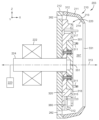
도 3a는 웨이퍼 파지 디바이스(203)의 예시적인 실시예를 예시한다. 예시된 바와 같이, 웨이퍼 파지 디바이스(203)는, 도 2a에 예시된, 파지기 조립체(220) 및 캐치 컵(210)을 포함한다. 파지기 조립체(220)는 적어도 세정 주기 동안 처리 용적(297) 내에 위치된다.3A illustrates an exemplary embodiment of a wafer
파지기 조립체(220)는 제1 플레이트 조립체(318), 제2 플레이트 조립체(320), 로딩 핀들(311), 및 파지 핀들(315)을 포함한다. 파지기 조립체(220)는 세정 프로세스의 세정 주기 동안 제1 플레이트 조립체(318) 및 제2 플레이트 조립체(320)를 회전시키기 위해 구동 모터(222)에 의해 구동될 수 있는 샤프트(224)에 결합된다. 또한, 샤프트(224)는 로딩 위치, 언로딩 위치, 헹굼 위치 및 세정 위치 내외로 제1 및 제2 플레이트 조립체들(318, 320)을 이동시키도록 구동될 수 있다. 또한, 세정 프로세스 동안 제1 플레이트 조립체(318)의 애퍼쳐(351)를 통해 웨이퍼(151)의 후방 측에 세정 유체들이 도포되도록 세정 유체들이 샤프트(224)를 통해 유동할 수 있다. 일 실시예에서, 샤프트(224)는 샤프트(224)가 +X 및 -X 방향들로 병진되는 동안 파지기 조립체(220)가 회전되는 것을 허용하는 스플라인 샤프트일 수 있다.The
파지 핀들(315)은 세정 프로세스 동안 웨이퍼(151)를 파지하거나 유지할 수 있다. 파지 핀들(315)은 웨이퍼(151)를 수용하도록 구성된 성형된 영역을 포함할 수 있다. 예를 들어, 파지 핀들(315)은 웨이퍼(151)의 에지를 수용하도록 성형된 노치 영역을 포함할 수 있다. 또한, 파지 핀들(315)은 제2 플레이트 조립체(320) 내에 수납될 수 있다. 추가적으로 또는 대안적으로, 파지 핀들(315)은 제2 플레이트 조립체(320)에 결합될 수 있다. 파지 핀들(315)은 서로로부터 약 120 °로 배치될 수 있다. 대안적으로, 파지 핀들(315)은 서로로부터 120 ° 미만 또는 서로로부터 120 ° 초과로 배향될 수 있다. 또한, 파지 핀들(315)의 총 개수는 1개 이상일 수 있다. 대안적으로, 파지 핀들(315)의 총 개수는 2개 이상이다. 또한, 파지 핀들(315)의 총 개수는 3개 이상이다. 파지 핀들(315)은 제1 플레이트 조립체(318) 내의 개구부들을 통과할 수 있으며, 이로써, 파지 핀들(315)은 세정 주기 동안 웨이퍼(151)를 파지하거나 유지할 수 있다. 파지 핀들(315)은, 파지 핀들(315)이 웨이퍼(151)의 세정 프로세스를 방해하지 않도록, 웨이퍼(151)의 에지를 따라 웨이퍼(151)와 최소한의 접촉을 가질 수 있다.The gripping pins 315 can grip or hold the
로딩 핀들(311)은 로딩 및/또는 언로딩 프로세스 동안 웨이퍼(151)를 파지하거나 유지할 수 있다. 또한, 로딩 핀들(311)은 제1 플레이트 조립체(318)에 결합된다. 파지기 조립체(220)가 세정 위치와 로딩 또는 언로딩 위치 사이에서 이동될 때, 로딩 핀들(311)은 제1 플레이트 조립체(318)와 함께 이동된다. 로딩 핀들(311)은 웨이퍼(151)를 수용하도록 구성된 성형된 영역을 포함할 수 있다. 예를 들어, 로딩 핀들(311)은 웨이퍼(151)의 에지를 수용하도록 성형된 노치 영역을 포함할 수 있다. 로딩 핀들(311)은, 로딩 핀들(311)이 웨이퍼(151)의 세정 프로세스를 방해하지 않도록, 웨이퍼(151)의 에지를 따라 웨이퍼(151)와 최소한의 접촉을 갖도록 구성될 수 있다. 로딩 핀들(311)은 서로로부터 약 120 °로 배치될 수 있다. 대안적으로, 로딩 핀들(311)은 서로로부터 120 ° 미만 또는 서로로부터 120 ° 초과로 배향될 수 있다. 또한, 로딩 핀들(311)의 총 개수는 1개 이상, 2개 이상, 또는 3개 이상일 수 있다.The loading pins 311 may grip or hold the
파지 핀들(315) 및 로딩 핀들(311)의 개수는 동일할 수 있다. 대안적으로, 파지 핀들(315)의 개수는 로딩 핀들(311)의 개수를 초과할 수 있다. 또한, 파지 핀들(315)의 개수는 로딩 핀들(311)의 개수보다 적을 수 있다.The number of
제1 플레이트 조립체(318) 및 로딩 핀들(311)은 웨이퍼 로딩 프로세스 동안 활용될 수 있다. 또한, 제2 플레이트 조립체(320) 및 파지 핀들(315)은 로딩 프로세스 동안 웨이퍼와의 간섭이 없도록 위치된다. 예를 들어, 제1 플레이트 조립체(318)는 제2 플레이트 조립체(320)에 대해 이동할 수 있고, 제1 플레이트 조립체(318)를 제1 캐치 컵(211) 외부에 그리고 파지 핀들(315)을 로딩 위치에 위치시킨다. 또한, 파지 핀들(315)과 파지기 조립체(220)의 중심 사이의 거리가 증가된다. 추가적으로, 파지 핀들(315)은 로딩 핀들(311) 뒤에 위치될 수 있고, 웨이퍼(151)가 로딩 핀들(311) 상에 수직으로 로딩되고/거나 언로딩되는 명확한 경로를 제공한다.The
캐치 컵(210)의 벽(213)은 제2 플레이트 조립체(320) 및/또는 파지 핀들(315) 중 하나 이상과 상호작용하도록 성형된다. 벽(213)은 위에서 설명된 바와 같이 캐치 컵(210)의 일부일 수 있거나, 환형 벽은 제1 캐치 컵(211)의 일부일 수 있다. 벽(213)은 제2 플레이트 조립체(320)의 피쳐(312)와 상호작용할 수 있도록 적어도 하나의 경사진 부분을 포함한다. 또한, 벽(213)은 웨이퍼(151)로부터 멀리 그리고 드레인(284) 내로 수분을 안내하는 것을 보조하고, 세정 프로세스 동안 웨이퍼(151) 상의 입자 재부착을 감소시킨다. 예를 들어, 이하에서 더 상세히 설명될 바와 같이, 파지기 조립체(220)가 웨이퍼 로딩 위치에 있을 때, 피쳐들(312)은 제1 플레이트 조립체(318)가 제2 플레이트 조립체(320)에 대해 이동하는 것을 허용하기 위해 벽(213)과 상호작용한다.The
또한, 캐치 컵(210)은 개구부(331)를 포함할 수 있다. 개구부(331)의 직경은 제1 플레이트 조립체(318)가 통과하는 것을 허용하기에 충분히 클 수 있지만, 제2 플레이트 조립체(320)가 통과하는 것을 허용하기에는 충분히 크지 않을 수 있다. 예를 들어, 개구부(331)의 직경은 제1 플레이트 조립체(318)보다 크고 제2 플레이트 조립체(320)보다 작을 수 있다.Also, the
캐치 컵(210)은 웨이퍼(151), 파지기 조립체(220), 및 캐치 컵(210)이 구동 모터(222)에 의해 회전되는 동안 수분이 드레인(284) 내로 유동하도록 캐치 컵(210)의 에지를 따라 어레이로 위치된 드레인 홀들(262)을 포함할 수 있다. 또한, 제2 캐치 컵(212)은 드레인 홀들(262)을 포함할 수 있다. 수분은 드레인 홀들(370)을 통해 드레인(284)(도 2a) 내로 유동하고, 여기서 세정 모듈(200)로부터 제거된다.
도 3a에 예시된 바와 같이, 파지기 조립체(220)는, 웨이퍼(151)를 수용하고 웨이퍼(151)를 세정 위치에 배치하는 것을 보조하기 위해 서로에 대해 이동하도록 구성된, 제1 플레이트 조립체(318) 및 제2 플레이트 조립체(320)를 포함한다. 구체적으로, 도 3c 및 3d는 각각 후퇴 위치(예를 들어, 세정 위치)(300a) 및 연장 위치(300b)에서의 파지기 조립체(220)의 실시예를 예시한다. 파지기 조립체(220)는 세정 프로세스 동안 후퇴 위치(300a)에 위치될 수 있다. 또한, 파지기 조립체(220)는 웨이퍼 로딩 프로세스 및/또는 웨이퍼 제거(언로딩) 프로세스 동안 연장 위치(예를 들어, 로딩 위치)(300b)에 위치될 수 있다. 또한, 연장 위치(300b)는 세정 모듈(200) 내의 파지기 조립체(220)의 로딩 위치에 대응할 수 있다. 로딩/언로딩 위치는 또한, 웨이퍼(151)에 대한 헹굼 위치로서 기능할 수 있다. 예를 들어, 헹굼을 위해 로딩/언로딩 위치에 위치될 때, 탈이온수 및/또는 다른 세정 화학물질들이 최상부 스프레이 바들(290)로부터 웨이퍼(151) 상으로 전달될 수 있다. 추가적으로, 파지기 조립체(220)가 로딩 위치에 있을 때, 파지기 조립체(220)는 파지기 조립체(220)가 세정 위치에 위치되는 곳으로부터 X 방향으로 소정 거리에 위치된다. 일 실시예에서, 제1 플레이트 조립체(318)의 결합 표면(301)은 샤프트(224)에 결합되고 샤프트(224)에 의해 구동된다.As illustrated in FIG. 3A , the
하나 이상의 스프링 메커니즘(330)이 제1 플레이트 조립체(318)를 제2 플레이트 조립체(320)에 결합시킬 수 있다. 스프링 메커니즘들(330)은 스프링(331) 및 결합 부재(333)를 포함할 수 있다. 스프링 메커니즘들(330)은 피쳐들(또는 요소들)(312)이 제1 캐치 컵(211)과 접촉할 때 제1 플레이트 조립체(318)가 제2 플레이트 조립체(320)에 대해 이동하는 것을 허용한다. 예를 들어, 제2 플레이트 조립체(320)는 파지기 조립체(220)가 양의 X 방향으로(예를 들어, 제1 캐치 컵(211)을 향해 수평으로) 이동될 때 벽(213)과 상호작용하도록 구성된 피쳐들(312)을 포함한다. 일 실시예에서, 스프링 메커니즘들(330) 각각은 결합 부재(333) 위로 또는 그와 평행하게 이동하는 하나 이상의 스프링(331)을 포함할 수 있다.One or
파지 핀들(315)은 적어도 하나의 다른 핀에 대해 이동하도록 구성될 수 있다. 예를 들어, 파지 핀들(315)은, 다른 핀들 중 하나 이상으로부터 파지 핀들(315)을 멀리 이동시키는 하나 이상의 요소를 포함할 수 있다. 파지 핀들(315)은 세정 프로세스 동안 웨이퍼(예를 들어, 웨이퍼(151))를 파지하도록 구성될 수 있다. 또한, 로딩 핀들(311)은 로딩 및 언로딩 프로세스 동안 웨이퍼(151)를 파지하거나 유지하도록 구성될 수 있다. 다른 실시예들에서, 파지 핀들(315)은 웨이퍼를 로딩 핀들에 대해 유지하기 위해 이동될 수 있다.The gripping pins 315 may be configured to move relative to at least one other pin. For example, the gripping
파지기 조립체(220)는 또한, 제1 플레이트 조립체(318)에 대한 제2 플레이트 조립체(320)의 각도 운동을 제한하도록 구성된 안내 핀(317)을 포함할 수 있다.The
하나 이상의 실시예에서, 각각의 파지 핀(315)은 파지 핀들(315) 중 하나 이상에 병진 운동을 부여하는 제1 캐치 컵(211)의 하우징과 접촉하도록 구성된 요소(380)에 결합될 수 있다. 예를 들어, 요소(380)가 제1 캐치 컵(211)과 접촉하는 것에 응답하여, 파지기 조립체(220)가 +X 방향으로 이동될 때, 파지 핀(315)은 축(302)을 중심으로 피벗하고 파지기 조립체(220)의 외측 에지를 향해 이동된다. 도 3b는 요소들(380)이 제1 캐치 컵(211)과 방금 접촉했고 폐쇄 위치에 있는 예시적인 실시예를 예시한다. 일 실시예에서, 파지기 조립체(220)가 +X 방향으로 이동될 때, 요소들(380)은 제1 캐치 컵(211)과 접촉하고 축들(302)을 중심으로 피벗한다. 응답 시에, 요소들(380)에 결합된 파지 핀들(315) 상에 병진 운동이 부여된다. 일 실시예에서, 요소들(380)은 +X 방향으로의 파지기 조립체(220)의 이동이 정지될 때까지 계속 피벗한다. 일 실시예에서, 요소들(380) 및 파지 핀들(315)은 +X 방향으로의 파지기 조립체(220)의 이동이 정지된 후에 개방 위치에 위치된다.In one or more embodiments, each
또한, 요소(380)는 스프링 요소(381)에 결합될 수 있다. 스프링 요소(381)는 요소(380)를 시작 위치로 더 복귀시킬 수 있고, 요소(380)가 제1 캐치 컵(211)의 하우징과 더 이상 접촉하지 않는 것에 응답하여 파지 핀(315)을 파지 위치로 이동시킨다. 스프링 요소(381)는 요소(380)를 로딩할 수 있고, 이로써, 요소(380)는 요소(380)가 제1 캐치 컵(211)의 하우징과 더 이상 접촉하지 않을 때 시작 위치로 복귀한다. 또한, 스프링 요소(381)는 리프 스프링 또는 임의의 다른 스프링 설계일 수 있다.Additionally,
로딩 핀들(311) 및 파지 핀들(315)은 웨이퍼(151)가 파지기 조립체(220)의 제1 플레이트 조립체(318)와 접촉하지 않도록 웨이퍼(151)를 유지하도록 구성될 수 있다. 또한, 제1 캐치 컵(211)에 대한 웨이퍼(151)의 위치는 세정 주기 동안 조정가능할 수 있다.The loading pins 311 and the
도 3f는, 단부(380a)가 제1 캐치 컵(211)과 접촉하지 않는, 폐쇄 위치에서의 요소(380) 및 파지 핀(315)의 실시예를 예시한다. 도 3g는 개방 위치에서의 요소(380) 및 파지 핀(315)을 예시한다. 도 3g의 예시된 실시예에서, 요소(380)의 단부(380a)는 제1 캐치 컵(211)과 접촉한다. 또한, 요소(380)는 요소(380)의 단부(380b)가 단부(380a)에 대해 이동되도록 피벗되었다. 일 실시예에서, 단부(380b)는 제2 플레이트 조립체(320)의 상부 표면을 향해 회전되었다. 추가적으로, 파지 핀(315)이 또한 이동되었고, 이로써, 제1 캐치 컵(211)을 향해 외측으로 기울어졌다.3F illustrates an embodiment of
도 3c를 더 참조하면, 파지기 조립체(220)는 하나 이상의 애퍼쳐(351)를 더 포함한다. 하나 이상의 실시예에서, 세정 유체들은 애퍼쳐(들)(351)를 통해 웨이퍼(151)의 후방 측 상으로 유동할 수 있다. 세정 유체들은 헹굼제(예를 들어, 탈이온수, 오존수) 또는 세정 화학물질일 수 있다. 또한, 세정 유체들은 샤프트(224)를 통해 그리고 이어서 애퍼쳐들(351)에 제공될 수 있다.With further reference to FIG. 3C , the
도 3e는 파지기 조립체(220)의 개략적인 부분 평면도를 도시한다. 애퍼쳐(들)(351)는 웨이퍼(151)의 후방 측 상에 화학물질들을 유동시킨다. 하나 이상의 애퍼쳐(351)는 실질적으로 원형 또는 선형 패턴으로 배치될 수 있다. 애퍼쳐들(351) 각각은, 세정 유체가 웨이퍼(151)의 후방 표면에 걸쳐 균등하게 유동하도록 실질적으로 동일한 크기일 수 있다. 또한, 적어도 하나의 애퍼쳐(351)는 적어도 하나의 다른 애퍼쳐와 상이한 크기일 수 있다.3E shows a schematic partial plan view of
도 4a는 스위프 암(230)에 부착된 노즐 메커니즘(240)의 저면도이다. 예시된 바와 같이, 노즐 메커니즘(240)은 노즐(410), 노즐(420) 및 노즐(430)을 포함한다. 대안적으로, 노즐(420) 및 노즐(430) 중 하나 이상이 생략될 수 있다. 또한, 노즐 메커니즘(240)은 3개 초과의 노즐들을 포함할 수 있다. 노즐(410)은 웨이퍼(151)의 표면에 대해 제1 각도(예를 들어, 도 4b의 각도(412))로 배치될 수 있고, 노즐(420)은 웨이퍼(151)의 표면에 대해 제2 각도(예를 들어, 도 4b의 각도(422))로 배치될 수 있고, 노즐(430)은 웨이퍼(151)의 표면 또는 제1 플레이트 조립체(318)의 표면에 대해 제3 각도(예를 들어, 도 4b의 각도(432))로 배치될 수 있다. 각도(412)는 각도들(422 및 432) 중 적어도 하나와 상이할 수 있다. 또한, 각도들(422 및 432)은 실질적으로 유사할 수 있다. 일부 구성들에서, 노즐(410)은 웨이퍼의 표면에 대해, 노즐(420) 및 노즐(430)이 웨이퍼의 표면에 대해 배치되는 각도들(예를 들어, 422 및 432)보다 작은 각도(예를 들어, 각도(412))로 배치될 수 있다. 일부 구성들에서, 각도(412)는 제1 플레이트 조립체(318) 또는 웨이퍼(151)의 표면에 대해 약 30 ° 내지 약 50 °일 수 있고, 각도들(422 및 432)은 웨이퍼(151)의 표면 또는 제1 플레이트 조립체(318)의 표면에 대해 약 80 ° 내지 약 100 °에 있다. 일 실시예에서, 각도(412)는 웨이퍼(151)의 표면 또는 제1 플레이트 조립체(318)의 표면에 대해 약 45 °이고, 각도들(422 및 432)은 웨이퍼(151)의 표면 및 제1 플레이트 조립체(318)의 표면에 대해 약 90 °(또는 수직)이다. 또한, 다른 각도들이 활용될 수 있다. 추가적으로 또는 대안적으로, 각도들(412, 422 및 432)은 각각 약 80 ° 내지 약 100 °일 수 있다. 또한, 노즐들(410, 420 및/또는 430) 각각의 위치는 웨이퍼 상의 특정 방사상 위치들을 목표로 하기 위해 스위프 암(230)의 길이를 따른 방향으로 조정될 수 있다. 추가적으로, 각각의 노즐에 대한 각도 및 위치는 웨이퍼(151)의 표면으로부터 임의의 오염물들을 제거하기 위해 각각의 노즐에 의해 출력되는 세정 유체들이 함께 기능하도록 선택될 수 있다.4A is a bottom view of
노즐 메커니즘(240)은 노즐들(410, 420 및 430)을 통해 웨이퍼(151)의 제1 표면 상에 세정 매체를 출력하도록 구성될 수 있다. 세정 매체는 헹굼제들 및 세정 화학물질들을 포함할 수 있다. 또한, 노즐 메커니즘(240)은 노즐(410)을 통해 제1 세정 매체를, 노즐(420)을 통해 제2 세정 매체를, 그리고 노즐(430)을 통해 제3 세정 매체를 출력하도록 구성된다. 추가적으로, 노즐들(410, 420 및 430) 중 하나 이상은 하나 이상의 헹굼제를 도포하도록 구성된다.
노즐 메커니즘(240)은 하나 이상의 비접촉 세정 기법을 포함할 수 있다. 노즐들(410, 420 및 430)은 액체, 가스, 및 미립자의 임의의 조합인 매체를 출력할 수 있다. 또한, 노즐들(410, 420 및 430) 중 하나 이상은 고에너지 매체를 출력하도록 구성되는 고에너지 노즐일 수 있다. 고에너지 매체는 액체, 가스 및 미립자의 임의의 조합일 수 있다. 또한, 고에너지 매체는 고에너지 세정 화학물질일 수 있다. 노즐들(410, 420 및 430) 중 하나 이상은 메가소닉 노즐, 유체 제트 노즐, 또는 운동 에너지 노즐일 수 있다. 예를 들어, 노즐(410)은, 가스와 액체의 혼합물을 전달하도록 구성된, 메가소닉 노즐, 제트 노즐, 및 운동 에너지 노즐 중 하나이다. 메가소닉 노즐은 메가소닉 작동 유체를 생성하기 위해 사인파 또는 다른 패턴에 따라 교번 방식으로 세정 유체에 밀함 및 소함을 교번적으로 적용하도록 구성된 하나 이상의 요소를 포함한다. 예를 들어, 메가소닉 노즐은 메가소닉 작동 유체를 생성하기 위해 950 kHz의 속도의 사인파 패턴으로 밀함 및 소함을 교번적으로 적용하도록 구성될 수 있다. 대안적으로, 다른 주파수들이 사용될 수 있다.
노즐(420)은 제1 화학물질을 도포하도록 구성되고, 노즐(430)은 헹굼제를 도포하도록 구성된다. 또한, 노즐(410)이 메가소닉 노즐인 경우, 노즐(420)은 제1 화학물질을 도포하도록 구성되고, 노즐(430)은 제2 화학물질을 도포하도록 구성된다. 대안적으로, 노즐(410)이 메가소닉 노즐인 경우, 노즐(420)은 제1 헹굼제를 도포하도록 구성되고, 노즐(430)은 제2 헹굼제를 도포하도록 구성된다. 또한, 노즐들 중 적어도 2개는 동일한 헹굼제 또는 화학물질을 도포하도록 구성된다.
세정 유체들은 유체 연결부들(440)을 통해 노즐 메커니즘(240)에 제공될 수 있다. 연결부들의 개수는 노즐 메커니즘 내의 노즐들의 개수 및/또는 노즐 메커니즘(240)에 의해 활용되는 상이한 유형들의 화학물질들 및/또는 헹굼제들의 개수에 기초할 수 있다. 예를 들어, 노즐 메커니즘(240)이, 2개의 상이한 세정 유체들을 출력하도록 구성된 3개의 노즐들을 채용하는 경우, 2개의 연결부들(440)이 활용될 수 있다. 또한, 상이한 노즐들을 통한 상이한 세정 화학물질들 및/또는 헹굼제들의 유량은 변화될 수 있다. 예를 들어, 노즐들(410, 420 및 430) 중 제1 노즐로부터의 세정 화학물질 또는 헹굼제의 유량은 노즐들(410, 420 및 430) 중 제2 노즐로부터의 세정 화학물질 또는 헹굼제의 유량과 상이할 수 있다. 대안적으로, 노즐들(410, 420 및 430) 중 적어도 하나로부터의 세정 화학물질 또는 헹굼제의 유량은 세정 프로세스 및/또는 헹굼 프로세스 동안 변화될 수 있다.Cleaning fluids may be provided to
도 4는 3개의 별개의 노즐들을 예시하지만, 다른 실시예들에서, 다른 개수의 노즐들이 활용될 수 있다. 예를 들어, 3개 초과의 노즐들이 활용될 수 있다. 또한, 3개 미만의 노즐들이 활용될 수 있다.4 illustrates three separate nozzles, in other embodiments other numbers of nozzles may be utilized. For example, more than three nozzles may be utilized. Also, fewer than three nozzles may be utilized.
도 5는 노즐 메커니즘(240)의 대안적인 실시예를 예시한다. 도 4의 실시예와 비교하여, 모든 연결부들(440)이 노즐 메커니즘(240)의 공통 측에 연결되는 대신에, 제1 연결부(442)가 노즐 메커니즘(240)의 제1 측에 연결되고 제2 연결부(444)가 노즐 메커니즘의 제2 측에 연결되며, 여기서 제1 측은 제2 측과 상이하다.5 illustrates an alternative embodiment of
이제 도 2a로 돌아가면, 스위프 암(230)은 스위프 암 샤프트(232) 및 스위프 암 구동 모터(234)에 결합된다. 스위프 암 샤프트(232) 및 스위프 암 구동 모터(234)는 스위프 암 구동 조립체(236)를 형성한다. 스위프 암 구동 조립체(236)는 세정 프로세스 동안 웨이퍼(151)의 표면에 걸쳐 노즐 메커니즘(240)을 이동시키도록 구성되고, 이로써, 노즐 메커니즘(240)에 의해 출력되는 세정 유체들은 웨이퍼(151)의 표면에 걸쳐 균등하게 분배된다. 스위프 암 구동 조립체(236)는 또한, 노즐 메커니즘(240)과 웨이퍼(151)의 표면 사이의 거리를 설정하기 위해 스위프 암(230)을 축방향으로 이동시키도록 구성될 수 있다.Turning now to FIG. 2A ,
도 6은 하나 이상의 실시예에 따른, 세정 주기 동안 웨이퍼(151)에 걸친 스위프 암(230) 및 노즐 메커니즘(240)의 경로(610)를 예시한다. 도 6에 예시된 바와 같이, 웨이퍼(151)는 파지기 조립체(220) 위에 배치되고 그에 의해 유지된다. 경로(610)는 웨이퍼(151)의 디바이스 측 표면(전방 표면)에 평행한 아치형 경로일 수 있다. 대안적으로, 경로들의 다른 형상들 및/또는 길이들이 활용될 수 있다. 예를 들어, 스위프 암(230)의 운동 범위는 변화될 수 있다. 도 6에 예시된 바와 같이, 스위프 암(230)의 단부에 결합된 노즐 메커니즘(240)은 아치형 경로로 웨이퍼의 중심 위를 지나간다. 스위프 암(230) 및/또는 노즐 메커니즘(240)의 위치는 노즐 메커니즘(240)이 처리 동안 회전하는 웨이퍼(151)의 중심 위를 지나가는 것을 보장하도록 조정될 수 있다. 또한, 스위프 암(230)의 위치 및 노즐 메커니즘(240)의 위치 중 적어도 하나는 노즐 메커니즘(240)이 웨이퍼(151)의 중심 이외의 웨이퍼(151)의 부분 위를 지나가도록 조정될 수 있다. 예를 들어, 웨이퍼(151)의 표면에 대한 노즐 메커니즘(240)의 위치를 변화시키기 위해, 노즐 메커니즘(240)이 스위프 암(230)에 대해 이동될 수 있고/거나 스위프 암(230)이 스위프 암 샤프트(232)에 대해 이동될 수 있다. 또한, 노즐 메커니즘(240)과 웨이퍼(151)의 표면 사이의 축방향 거리는 세정 프로세스에서 보조하기 위해 변화될 수 있다.6 illustrates a
스위프 암 구동 모터(234)는 세정 프로세스 동안 스위프 암 샤프트(232)를, 그리고 차례로 스위프 암(230) 및 노즐 메커니즘(240)을 웨이퍼(151)에 걸쳐 이동시킨다. 스위프 암 구동 모터(234)는 노즐 메커니즘(240)의 스캔 속도를 제어할 수 있다. 예를 들어, 스위프 암 구동 모터(234)는 노즐 메커니즘이 경로(610)를 따라 이동하며 스캔하는 속도를 제어할 수 있다.Sweep
도 6은 스프레이 바들(290)을 더 예시한다. 스프레이 바들(290)은 웨이퍼가 세정 모듈(200) 내로 삽입될 때 웨이퍼(151)를 사전 처리하고, 웨이퍼가 세정 모듈(200)로부터 제거될 때 웨이퍼(151)를 헹굼할 수 있다. 스프레이 바들(290)은 구성된 하나 이상의 유체를 출력하도록 구성된 하나 이상의 노즐을 포함할 수 있다. 대안적으로, 스프레이 바들(290)은 스프레이 바(290)에 걸쳐 균일한 유동을 유지하도록 설계된 홀들을 갖는 튜브를 포함할 수 있다. 예를 들어, 웨이퍼(151)가 세정 모듈(200)의 안팎으로 이송될 때 웨이퍼(151)가 스프레이 바들(290)을 지나갈 때, 스프레이 바들(290)은, 웨이퍼(151)가 이송 프로세스 동안 젖은 상태로 유지되고, 입자들은 입자들이 세정 모듈(200)로부터 제거될 때 웨이퍼(151)에 재부착되지 않는 것을 보장하기 위해, 웨이퍼(151)에 헹굼 유체를 도포한다.6 further illustrates spray bars 290 . The spray bars 290 may pre-treat the
도 7a는 세정 모듈(200) 내의 공기 유동 패턴의 예를 예시한다. 공기 유동 패턴에 의해 예시된 바와 같이, 공기 유동이 플레넘(280) 밖으로 그리고 배기부(260) 밖으로 유동할 때 재순환이 최소화된다. 일반적으로, 벽(213)의 환형 내측 표면(214) 및 캐치 컵(210)의 외측 표면의 형상은, 웨이퍼가 회전 축(313)을 중심으로 회전될 때 웨이퍼의 표면으로부터 유동되는 유체들을 포획하고 공기 재순환을 감소시키는 것을 보조한다. 일 실시예에서, 벽(213)의 환형 내측 표면(214)은 처리 용적(297) 내의 공기 유동이 파지기 조립체(220)의 외측 에지를 따라 배기부(260) 내로 가도록 반전된 형상을 갖는다. 또한, 캐치 컵(210)의 외측 표면은 내부 용적(295) 내의 공기 유동이 캐치 컵(210)의 외부 주위에 그리고 배기부(260) 내로 가도록 성형될 수 있다. 또한, 캐치 컵(210)의 외측 표면의 형상은 공기 유동의 대부분을 캐치 컵(210)의 외부 주위로 그리고 배기부(260) 내로 이동하도록 강제할 수 있다.7A illustrates an example of an air flow pattern within
드레인 홀들(262)의 하나 이상의 측은 경사질 수 있고, 이로써, 드레인 홀들(262)의 측들 사이의 거리는 상이하다. 예를 들어, 드레인 홀들(262)은 점감될 수 있다. 드레인 홀들을 점감시키는 것은 캐치 컵(210) 내부의 영역으로부터 유체 펌핑 속도를 증가시킬 수 있다. 또한, 래버린스(264)가 캐치 컵(210)과 세정 모듈(200)의 하우징 사이에 형성될 수 있다. 래버린스(264)는 수분이 래버린스들(264)을 통해 내부 용적(295) 내로 다시 유동하는 것을 적어도 부분적으로 제한하도록 구성될 수 있다.One or more sides of the drain holes 262 may be inclined, so that the distance between the sides of the drain holes 262 is different. For example, drain holes 262 may be tapered. Tapping the drain holes can increase the rate of fluid pumping from the area inside the
플레넘(280)은 재순환을 최소화하기 위해 세정 모듈(200) 내의 공기 유동을 제어하도록 구성될 수 있다. 예를 들어, 플레넘(280)은 재순환을 최소화하기 위해 세정 모듈(200) 내로 유동하는 공기의 양을 증가시키고/거나 감소시킬 수 있다. 본원에 개시된 캐치 컵(210), 파지기 조립체(220), 플레넘(280), 배기부(260), 스프레이 바(290), 드레인(284), 및 공기 흡입구(270)의 구성으로 인해 공기 유동 재순환이 최소화될 수 있다.
일 실시예에서, 세정 프로세스 동안, 웨이퍼(151)의 표면에 걸친 균일한 공기 유동은 배기부(260) 및 플레넘(280)에 의해 생성된다. 다양한 실시예들에서, 배기부(260)는 입자들이 웨이퍼(151)의 표면에 재부착하는 것을 방지하기 위해 공기가 세정 모듈(200) 밖으로 유동하기 위한 경로를 제공하도록 구성된다. 위에서 설명된 바와 같이, 공기는 공기 흡입구(270)에 의해 플레넘(280)에 제공될 수 있고, 배기부(260)에 의해 세정 모듈(200)로부터 배기될 수 있다. 플레넘(280)은 샤워헤드 양식의 플레넘일 수 있다. 또한, 배기부(260)의 기하형상 및/또는 캐치 컵(210)의 형상(또는 제1 캐치 컵(211) 및/또는 제2 캐치 컵(212)의 형상)은 세정 모듈(200) 내의 재순환을 감소시키도록 최적화될 수 있다. 재순환을 감소시키는 것은 웨이퍼(151) 상의 입자들 및 임의의 기화된 세정 유체들의 재부착을 적어도 최소화한다. 배기부(260)의 기하형상 및/또는 캐치 컵(210)의 형상(또는 제1 캐치 컵(211) 및/또는 제2 캐치 컵(212)의 형상)은 캐치 컵(210) 뒤에 래버린스(264)를 생성할 수 있고, 재순환을 최소화한다. 또한, 드레인(284)은 세정 모듈(200)로부터 세정 유체들 및 헹굼 유체들이 제거될 경로를 제공하고, 세정 모듈(200) 내의 재순환을 최소화한다. 플레넘(280)은 플레넘(280)이 노즐 메커니즘(240)에 근접하게 위치되고, 웨이퍼(151)가 플레넘(280)과 배기부(260) 사이에 있도록 세정 모듈(200)의 벽(283)을 따라 위치될 수 있다.In one embodiment, a uniform flow of air across the surface of
도 7b는 하나 이상의 실시예에 따른, 파지기 조립체(220), 애퍼쳐들(351) 및 드레인 홀들(262)의 부분의 개략적인 상면도이다. 드레인 홀들(262) 각각은 드레인(284)에 유체적으로 결합된다. 또한, 파지기 조립체(220), 캐치 컵(210) 및 웨이퍼(151)가 회전될 때, 유체는 드레인 홀들(262)을 통해 강제되고, 여기서 유체는 드레인(284)에 의해 세정 모듈로부터 제거된다.7B is a schematic top view of a portion of the
드레인 홀들(262)은 세정 프로세스 동안 수분이 드레인 홀들(262) 내로 유동하도록 캐치 컵(210)(또는 제2 캐치 컵(212))의 에지를 따라 위치될 수 있다. 드레인 홀들(262)은 세정 프로세스 동안 웨이퍼(151)의 표면으로부터 제거된 모든 입자들이 세정 모듈(200)로부터 제거되는 것을 보장하기 위해 세정 주기 동안 세정 모듈로부터 수분을 제거하는 것을 보조할 수 있다. 다양한 실시예들에서, 적어도 2개의 드레인 홀들(262)이 활용된다. 다른 실시예들에서, 2개보다 많은 드레인 홀들(262)이 활용된다.Drain holes 262 may be positioned along an edge of catch cup 210 (or second catch cup 212 ) such that moisture flows into
드레인 홀들(262)은 세정 모듈(200) 내의 공기 및/또는 유체 재순환을 감소시키도록 구성될 수 있다. 예를 들어, 드레인 홀들(262)의 크기 및/또는 배향은 공기 및/또는 유체 재순환을 감소시키도록 구성될 수 있다. 드레인 홀들(262)은 캐치 컵(210)(또는 제2 캐치 컵(212))의 표면과 경사진 또는 기울어진 배향을 가질 수 있다.Drain holes 262 may be configured to reduce air and/or fluid recirculation within
일 실시예에서, 드레인(284) 및/또는 배기부(260)는 배기 홀들(또는 포트들)(262) 내로의 수분의 유동을 최소화하는 하나 이상의 내부 래버린스 밀봉을 포함할 수 있다.In one embodiment, drain 284 and/or
드레인(284)은 세정 모듈(200)로부터 세정 주기의 완료 시에 과잉 수분 및/또는 모든 유체들을 제거하는 데 활용될 수 있다. 일 실시예에서, 수분은 드레인 홀들(262)을 통해 드레인(284) 내로 유동한다. 예를 들어, 웨이퍼(151)가 회전될 때, 드레인 홀들(262)은 수분이 웨이퍼(151) 상에 수집되지 않고 드레인(284)을 통해 제거되는 것을 보장하도록 구성된다. 일 실시예에서, 드레인(284)이 세정 모듈(200)과 만나는 곳에 하나 이상의 O-링 또는 다른 밀봉 부재들이 위치될 수 있다.
도 7b는 배기부(260)에 연결되고, 공기가 처리 용적(297) 내에서, 웨이퍼(151) 주위에 그리고 배기부(260) 내로 유동하기 위한 경로를 제공하도록 기능하는 배기 홀들(261)을 더 예시한다. 일 실시예에서, 배기 홀들(261)은 세정 모듈 내의 재순환을 최소화하는 것을 보조한다.7B further illustrates exhaust holes 261 that are connected to the
도 8은 하나 이상의 실시예에 따른, 웨이퍼(예를 들어, 웨이퍼(151))를 세정하기 위한 방법(800)을 예시한다. 작동(810)에서, 세정 모듈은, 이하에서 더 논의되는 도 9a에 예시된 바와 같이, 웨이퍼 로딩 위치에 배치된다. 예를 들어, 덮개(202)는 개방되고, 세정 모듈(200)의 파지기 조립체(220)는 회전 축(216)에 평행한 측방향(예를 들어, X 방향)으로 캐치 컵(210)의 벽(213)의 환형 내측 표면(214)을 향해 이동된다. 파지기 조립체(220)를 벽(213)을 향해 이동시키는 것은 파지기 조립체(220)를 로딩 위치에 배치한다. 일 실시예에서, 파지기 조립체(220)를 로딩 위치에 배치하는 것은 샤프트(224) 및 구동 모터(222)를 통해 벽(213)을 향해 파지기 조립체(220)를 이동시키는 것을 포함한다(예를 들어, 작동(812)). 예를 들어, 구동 모터(222)는 파지기 조립체(220)의 제2 플레이트 조립체(320)의 피쳐(312)가 벽(213)의 환형 내측 표면(214)과 접촉하도록 파지기 조립체(220)를 벽(213)을 향해 이동시키는 측방향으로 샤프트(224)를 구동한다. 피쳐(312)가 벽(213)과 접촉할 때, 제1 플레이트 조립체(318)의 적어도 부분이 내부 용적(295) 내에 위치되도록 제1 플레이트 조립체(318)가 계속 이동하는 동안 제2 플레이트 조립체(320)의 이동이 중단된다. 제1 플레이트 조립체(318)는 스프링 메커니즘들(330)을 통해 제2 플레이트 조립체(320)에 결합된 채로 유지된다. 예를 들어, 제1 플레이트 조립체(318)가 양의 X 방향으로 이동하고 제2 플레이트 조립체(320)의 이동이 중단될 때, 스프링 메커니즘들(330)이 팽창하고, 제1 플레이트 조립체(318)와 제2 플레이트 조립체(320) 사이의 결합을 유지한다.8 illustrates a
요소들(380) 각각은 파지 핀들(315) 중 각각의 파지 핀에 결합되고, 요소들(380)이 벽(213)과 접촉할 때, 파지 핀들(315) 각각은 서로 이동가능한 핀으로부터 멀리 기울어진다(또는 이동된다). 예를 들어, 도 9a에 도시된 바와 같이, 요소(380)가 벽(213)과 접촉할 때, 요소(380)는 피벗하고, 파지 핀(315)은 외측방향으로 이동되며, 파지기 조립체(220)의 중심으로부터 멀리 기울어진다. 파지 핀들(315)을 이동시키는 것은, 다른 핀들(예를 들어, 로딩 핀들(311) 및 파지 핀들(315) 중 다른 파지 핀들)로부터 멀리 기울어지고, 파지 핀들(315) 사이의 분리 거리가 증가되도록, 파지 핀들(315)을 파지기 조립체(220)의 외측 에지를 향해 이동시키는 것을 포함한다.Each of the
파지기 조립체(220)는, 웨이퍼(151)가 세정을 위해 수용될 수 있고/거나 세정 주기가 완료된 후에 웨이퍼(151)가 세정 모듈(200)로부터 제거될 수 있도록, 연장된 위치(300b)에 배치된다. 예를 들어, 파지기 조립체(220)는 제1 플레이트 조립체(318)의 적어도 부분이 캐치 컵(210)의 벽(213)을 넘어서 내부 용적(295) 내로 연장되고 연장된 위치(300b)에 있도록 구동 모터(222) 및 샤프트(224)에 의해 구동될 수 있다.The
도 9a는 파지기 조립체(220)가 로딩 위치에 위치되는 실시예를 도시한다. 도 9a의 실시예에서, 파지 핀들(315)은 외측으로 이동되었고, 제1 플레이트 조립체(318)는 제2 플레이트 조립체(320)로부터 멀리 이동되었다. 또한, 웨이퍼(151)가 로봇으로부터 로딩 핀들(311) 상으로 수용될 수 있도록 적어도 로딩 핀들(311)이 캐치 컵(210)의 외부에 그리고 내부 용적(295)에 존재한다. 로딩 위치에서, 제1 플레이트 조립체(318)의 표면(301)은 벽(213)의 외측 에지에 평행할 수 있거나, 처리 용적(297) 내의 캐치 컵(210)의 벽(213)으로부터 함몰될 수 있거나, 캐치 컵(210)의 벽(213)의 외부에 그리고 내부 용적(295)에 있을 수 있다. 대안적으로, 로딩 위치에 있을 때, 표면(301)은 벽(213)의 외측 에지에 평행하거나 처리 용적(297) 내에 있고, 한편 로딩 핀들(311)은 벽(213) 외부에 그리고 내부 용적(295)에 존재한다.9A shows an embodiment in which the
제어기(190)는 도 3a의 회전 축(313)을 따라 측방향으로 샤프트(224)를 이동시키고 파지기 조립체(220)를 측방향으로 이동시키기 위한 명령어들을 구동 모터(222)에 제공할 수 있다. 또한, 제어기(190)는 세정 모듈(200)이 세정을 위해 웨이퍼를 수용할 준비가 되어 있음을 나타내는 표시를 수신할 수 있다.The
방법(800)의 작동(820)에서, 세정을 위해 웨이퍼가 수용된다. 예를 들어, 일 실시예에서, 로봇(910)은 세정을 위해 웨이퍼(151)를 파지기 조립체(220) 내에 삽입한다. 도 9a의 실시예에 예시된 바와 같이, 로봇(910)은 웨이퍼(151)가 로딩 핀들(311)에 의해 유지되도록(예를 들어, 로딩 핀들(311)의 홈들에 놓이도록) 웨이퍼(151)를 삽입한다. 예를 들어, 로봇(910)은 웨이퍼(151)를 파지기 조립체(220)의 로딩 핀들(311) 내에 배치하도록 구성된다.In
세정 모듈(200)로의 진입 동안, 하나 이상의 스프레이 바(290)는 웨이퍼(151)가 세정 모듈(200) 내에 삽입될 때 웨이퍼(151)에 하나 이상의 유체를 도포함으로써 웨이퍼(151)를 사전 처리할 수 있다. 일 실시예에서, 웨이퍼(151)는 웨이퍼(151)가 하나 이상의 다른 세정 모듈(예를 들어, 메가소닉 세정 모듈들(161), 예비 세정 모듈들(162), 또는 브러쉬 박스 세정 모듈들(164)) 내에서 세정된 후에 수용될 수 있다.During entry into the
웨이퍼(151)가 로딩 핀들(311) 내에 완전히 삽입된 후, 로봇(910)은 웨이퍼(151)를 해제하고 세정 모듈(200)로부터 후퇴된다.After the
제어기(190)는 사전 처리 프로세스를 시작하기 위한 명령어들을 스프레이 바들(290)에 제공할 수 있다. 또한, 제어기(190)는 웨이퍼(151)가 세정 모듈(200) 내에 삽입되었다는 것을 나타내는 표시를 수신할 수 있다. 예를 들어, 제어기(190)는 웨이퍼(151)가 세정 모듈(200) 내에 배치되었음을 나타내는 센서 데이터를 감지 디바이스(294)로부터 수신하고, 스프레이 바들(290)이 사전 처리 프로세스를 시작하기 위한 명령어들을 생성할 수 있다.
방법(800)의 작동(830)에서, 세정 모듈이 세정 위치에 위치된다. 예를 들어, 세정 모듈(200)은 작동(832)에 도시된 바와 같이 파지기 조립체(220)를 벽(213)으로부터 멀리 이동시킴으로써 세정 위치에 배치될 수 있다. 구동 모터(222)는 파지기 조립체(220)를 처리 용적(297) 내로 후퇴시키기 위해 샤프트(224)를 구동한다. 예를 들어, 구동 모터(222)는 파지기 조립체(220)를 벽(213)으로부터 멀리 이동시키기 위해 샤프트(224)를 회전 축(216)을 따라 측방향 또는 수평 방향(예를 들어, X 방향)으로 구동할 수 있다.In
구동 모터(222)가 파지기 조립체(220)를 벽(213)으로부터 멀리 이동시킬 때, 제1 플레이트 조립체(318)는 제2 플레이트 조립체(320)와 다시 접촉하게 되고, 피쳐들(312)과 벽(213) 사이의 접촉이 종료된다. 또한, 요소들(380)은 폐쇄 위치로 피벗되고, 파지 핀들(315)은 서로를 향해 이동되고 웨이퍼(151)를 파지한다. 파지 핀들(315)은 웨이퍼(151)를 유지하기 위해 웨이퍼 상에 압력을 가한다. 파지 핀들(315) 각각은 웨이퍼(151)를 파지하기 위해 힘을 가하는 스프링 메커니즘에 결합될 수 있다. 구동 모터(222)는 제2 플레이트 조립체(320)가 캐치 컵(210)과 접촉할 때까지 샤프트(224)를 구동할 수 있다.When the
또한, 파지기 조립체(220)가 음의 X 방향으로(예를 들어, 벽(213)으로부터 수평으로 멀리) 이동될 때, 피쳐(312)는 벽(213)으로부터 멀리 이동하고 스프링 메커니즘들(330)은 제2 플레이트 조립체(320)를 제1 플레이트 조립체(318)에 클램핑된 상태로 유지한다. 제1 플레이트 조립체(318) 및 제2 플레이트 조립체(320)는 피쳐들(312)이 벽(213)과 더 이상 접촉하지 않을 때 서로 접촉하게 될 수 있다.Also, when the
도 9c의 실시예에 도시된 바와 같이, 웨이퍼(151)는 파지기 조립체(220)의 파지 핀들(315)에 의해 유지된다. 예시된 실시예에서, 파지 조립체(220)는, 요소들(380)이 벽(213)으로부터 멀리 이동되고 파지 핀들(315)이 웨이퍼(151)를 파지하도록, 벽(213)으로부터 멀리 X 방향으로(예를 들어, 회전 축(216)에 평행하게) 이동되었다. 또한, 로봇(910)은 세정 모듈(200)의 내부 용적(295)으로부터 후퇴되었다.As shown in the embodiment of FIG. 9C ,
제어기(190)는, 샤프트(224)를 벽(213)으로부터 멀리 측방향으로 이동시키고, 파지기 조립체(220)를 측방향으로 그리고 벽(213)으로부터 멀리 이동시키기 위한 명령어들을 구동 모터(222)에 제공하도록 구성될 수 있다. 제어기(190)는, 웨이퍼(151)가 파지기 조립체(220)에 의해 유지되고 있고 로봇(910)이 내부 용적(295)으로부터 제거되었다는 것을 나타내는, 감지 디바이스(294)로부터 수신된 센서 데이터에 기초하여 파지기 조립체(220)의 이동을 개시할 수 있다. 일단 파지기 조립체(220)가 후퇴 위치(300a)에 배치되면, 세정 주기가 개시될 수 있다.The
작동(840)에서, 웨이퍼가 세정된다. 웨이퍼(151) 및 파지기 조립체(220)는 처리 용적(297) 내에 완전히 존재하도록 세정 위치에 배치된다. 세정 주기를 수행하는 것은, 작동(842)에 의해 도시된 바와 같이, 스위프 암을 웨이퍼(151) 위에 위치시키는 것, 및 노즐 메커니즘(240) 및 샤프트(224)를 통해 웨이퍼(151)의 전방 및 후방 표면들 상에 유체들을 분배하는 것을 포함한다. 또한, 세정 주기를 수행하는 것은 작동(844)에 의해 도시된 바와 같이 웨이퍼(151)를 회전시키는 것을 포함한다. 예를 들어, 구동 모터(222)는 웨이퍼(151), 캐치 컵(210) 및 파지기 조립체(220)를 동시에 회전시킬 수 있다. 처리 용적(297) 내에서의 웨이퍼(151)의 위치는 세정 프로세스 동안 변경될 수 있다. 예를 들어, 웨이퍼(151)와 제2 캐치 컵(212) 사이의 거리는 변화될 수 있다. 노즐 메커니즘(240) 및 샤프트(224)를 통한 웨이퍼(151)의 전방 및 후방 표면들로의 유체들의 도포 속도는 변경될 수 있다. 예를 들어, 유체들은 동일한 속도로 또는 상이한 속도로 웨이퍼(151)의 전방 및 후방 표면들에 도포될 수 있다. 대안적으로, 유체들이 웨이퍼(151)의 전방 및 후방 표면들에 도포되는 속도는 세정 프로세스 또는 헹굼 프로세스 동안 변화될 수 있다. 예를 들어, 노즐 메커니즘을 통해 웨이퍼(151)의 전방 표면에 유체들이 도포되는 속도는 세정 또는 헹굼 프로세스 동안 증가되거나 감소될 수 있다. 또한, 샤프트(224)를 통해 웨이퍼(151)의 후방 표면에 유체들이 도포되는 속도는 세정 또는 헹굼 프로세스 동안 증가되거나 감소될 수 있다.In operation 840, the wafer is cleaned. The
웨이퍼(151)를 세정하는 것은 세정 유체들이 웨이퍼(151)의 제1 측(전방 표면) 및 제2 측(후방 표면)에 도포되는 동안 캐치 컵(210)(예를 들어, 제1 캐치 컵(211) 및 제2 캐치 컵(212)), 파지기 조립체(220) 및 웨이퍼(151)를 연속적으로 회전시키는 것을 포함한다. 세정 유체들이 도포되는 동안 캐치 컵(210), 파지기 조립체(220) 및 웨이퍼(151)를 회전시키는 것은 웨이퍼(151)의 어느 한 표면에의 입자들의 재부착을 최소화하고/거나 제거하는 것을 보조한다. 구동 모터(222)는 캐치 컵(210), 파지기 조립체(220) 및 웨이퍼(151)를 동시에 회전시키도록 구성될 수 있다. 예를 들어, 구동 모터(222)는 캐치 컵(210), 파지기 조립체(220), 및 웨이퍼(151)를 회전시키기 위해 샤프트(224)를 회전시킬 수 있다. 웨이퍼(151)는 유체들이 웨이퍼(151)의 표면으로부터 제거되도록 약 500 RPM 내지 약 1000 RPM 범위의 속도로 회전된다. 대안적으로, 웨이퍼(151)는 500 RPM 미만 또는 약 1000 RPM 초과의 속도들로 회전될 수 있다. 또한, 웨이퍼(151)가 회전되는 속도는 세정 프로세스 동안 변화될 수 있다.Cleaning the
제1 세정 유체들은 유체 공급원(223), 샤프트(224) 및 하나 이상의 애퍼쳐(351)를 통해 웨이퍼(151)의 후방 표면(예를 들어, 표면(301)을 향하는, 웨이퍼(151)의 표면)에 도포될 수 있다. 또한, 제2 유체들은 노즐 메커니즘(240)을 통해 웨이퍼(151)의 전방 표면(예를 들어, 표면(301)으로부터 멀어지는 쪽으로 향하는, 웨이퍼(151)의 표면)에 도포될 수 있다. 스위프 암 구동 모터(234)는 노즐 메커니즘(240)이 아치형 경로로 웨이퍼(151)의 전방 표면에 걸쳐 이동되도록 스위프 암(230)을 이동시킬 수 있다. 노즐 메커니즘(240)은 세정 프로세스 동안 세정 유체들을 웨이퍼(151)의 전방 표면에 도포하도록 구성될 수 있다. 유체들은 세정 화학물질들 및/또는 헹굼제들을 포함할 수 있다. 세정 유체들은 실질적으로 동시에 웨이퍼(151)의 전방 표면 및 후방 표면에 도포될 수 있다. 또한, 세정 유체들은 웨이퍼(151)의 후방 표면에 세정 유체들을 도포하는 것과 독립적으로 웨이퍼(151)의 전방 표면에 도포될 수 있다. 예를 들어, 하나 이상의 중첩 및 비중첩 기간 동안 세정 유체들은 웨이퍼(151)의 전방 표면에 도포될 수 있고 세정 유체들은 웨이퍼(151)의 후방 표면에 도포될 수 있다. 제1 비중첩 기간 동안 하나 이상의 세정 유체가 웨이퍼(151)의 전방 표면에 도포될 수 있고, 제2 비중첩 기간 동안 하나 이상의 세정 유체가 웨이퍼(151)의 후방 표면에 도포될 수 있다. 세정 주기의 중첩 및 비중첩 기간들은 임의의 순서로 발생할 수 있다. 또한, 중첩 및 비중첩 기간들의 횟수 및/또는 순서는 세정 주기마다 변할 수 있다. 추가적으로, 세정 위치에 있는 동안, 다시 웨이퍼(151) 상으로의 세정 유체들의 스플래싱이 적어도 감소되거나 제거된다.The first cleaning fluids may be applied to the backside surface of the wafer 151 (e.g., toward the
도 9d는 웨이퍼(151)가 세정 위치에 있는 실시예를 예시한다. 세정 위치는 파지기 조립체(220)를 처리 용적(297) 내에 위치시키는 것을 포함한다. 또한, 일단 웨이퍼 파지기(210)가 세정 위치에 배치되면, 세정 주기가 개시될 수 있다.9D illustrates an embodiment in which
세정 프로세스, 로딩 프로세스 및 언로딩 프로세스 중 적어도 하나 동안 세정 모듈(200) 내에서의 공기 유동은 재순환이 발생하는 것을 완화시키고, 입자들이 웨이퍼(151)의 표면에 재부착되는 것을 방지한다.Air flow within the
제어기(190)는 파지기 조립체(220)가 세정 위치에 위치된 것을 나타내는 표시를 수신할 수 있다. 표시는 감지 디바이스(294)로부터의 센서 데이터 내에 제공될 수 있다. 또한, 제어기(190)는 샤프트(224) 및 애퍼쳐(들)(351)를 통한 세정 유체들의 유동뿐만 아니라 노즐 메커니즘(240)을 통한 유체들의 운동 및 제어를 제어하도록 구성될 수 있다. 제어기(190)는 노즐 메커니즘(240)을 웨이퍼(151)의 표면에 걸쳐 이동시키기 위한 명령어들을 스위프 암 구동 모터(234)에 제공할 수 있다. 또한, 제어기(190)는 노즐들 중 하나 이상으로부터 세정 유체들을 분배하기 위한 명령어들을 노즐 메커니즘에 출력할 수 있다. 또한, 제어기(190)는 노즐들의 시기를 제어할 수 있고, 이로써, 세정 유체들은 상이한 시간들에서 출력된다. 예를 들어, 하나의 노즐은 다른 노즐 이전에 세정 유체들을 분배하기 시작하도록 제어될 수 있다. 노즐들 중 하나 이상은, 노즐들 중 적어도 다른 노즐이 세정 유체를 출력하지 않는 동안 세정 유체를 출력하도록 구성될 수 있다.The
작동(850)에서, 세정된 웨이퍼가 세정 모듈로부터 제거된다. 웨이퍼(151)를 세정 모듈들로부터 제거하는 것은, 파지기 조립체(220)를 언로딩 위치에 배치하기 위해 파지기 조립체(220)를 벽(213)을 향해 이동시키는 작동(852)을 포함한다. 언로딩 위치는, 파지기 조립체(220)의 제1 플레이트 조립체(318)를 적어도 부분적으로 내부 용적(295) 내로 이동시키고 파지 핀들(315)을 후퇴되고 기울어진 위치에 배치하는 것에 대응할 수 있다. 예를 들어, 로딩 위치는 핀들(311) 중 하나 이상 및 제1 플레이트 조립체(318)의 표면(301)을 내부 용적(295)에 위치시키는 것을 포함할 수 있다. 또한, 세정 모듈로부터 웨이퍼를 제거하는 것은, 세정 유체들의 분배를 정지시키는 작동(854), 및 웨이퍼의 회전을 정지시키는 작동(856)을 포함한다. 캐치 컵(210), 파지기 조립체(220), 및 웨이퍼(151)는 웨이퍼(151)가 내부 용적(295)에 있을 때까지 구동 모터(222)에 의해 연속적으로 회전될 수 있다.In
세정 주기의 끝에서, 파지기 조립체(220)는 구동 모터(222) 및 샤프트(224)에 의해 로딩 위치 내로 이동된다. 또한, 노즐 메커니즘(240)은 유체들의 분무를 중단시킬 수 있고, 노즐 메커니즘(240) 및 스위프 암(230)은 세정 주기의 끝에서 파지기 조립체(220)가 이동되기 전에 벽(213)으로부터 멀리 이동될 수 있다. 세정 주기의 끝에서, 노즐 메커니즘(240) 및 스위프 암(230)은 이들이 파지기 조립체(220) 및 로봇(910)의 이동을 방해하지 않도록 위치될 수 있다.At the end of the cleaning cycle,
세정 주기의 끝에서, 세정 유체들의 분배가 정지될 수 있다. 또한, 파지기 조립체(220)가 벽(213)을 향해 이동되기 전에, 세정 유체들의 분배가 정지될 수 있다. 대안적으로, 유체들은 최상부 표면으로의 유체들의 분배가 정지된 동안 웨이퍼(151)의 후방 표면 상에 계속 배치될 수 있다.At the end of the cleaning cycle, the dispensing of cleaning fluids may be stopped. Also, dispensing of the cleaning fluids may be stopped before the
또한, 파지기 조립체(220)가 이동되는 동안, 파지기 조립체(220) 및 캐치 컵(210)은 웨이퍼(151)로의 입자들의 재부착을 최소화하기 위해, 위에서 설명된 바와 같이 회전될 수 있다. 일 실시예에서, 파지기 조립체(220)가 이동하는 동안 파지기 조립체(220) 및 캐치 컵(210)을 회전시키는 것은 다시 웨이퍼(151) 상으로의 세정 유체들의 스플래싱을 감소시킨다. 또한, 파지기 조립체(220) 및 캐치 컵(210)의 회전은 요소들(380)이 벽(213)과 접촉하기 전에 정지된다. 추가적으로, 파지기 조립체(220) 및 캐치 컵(210)의 회전은 요소들(380)이 벽(213)과 접촉하기 직전에 정지될 수 있다.Additionally, while the
도 9a는, 로봇(910)이 웨이퍼(151)를 세정 모듈(200)로부터 제거할 수 있도록, 파지기 조립체(220)가 언로딩 위치에 위치되는 예시적인 실시예를 예시한다. 로봇(910)은 덮개(202)에 의해 차단되지 않은 개구부를 통해 세정 모듈에 접근하고, 깨끗한 웨이퍼(151)를 픽업하고, 깨끗한 웨이퍼(151)를 세정 모듈(200)로부터 제거할 수 있다.9A illustrates an exemplary embodiment in which the
제어기(190)는, 로봇(910)이, 세정된 웨이퍼(151)를 세정 모듈(200)로부터 제거할 수 있도록 파지기 조립체(220)를 언로딩 위치에 배치하기 위해, 샤프트(224)를 벽(213)을 향해 측방향으로 이동시키고, 파지기 조립체(220)를 측방향으로 그리고 벽(213)을 향해 이동시키기 위한 명령어들을 구동 모터(222)에 제공할 수 있다. 또한, 일단 웨이퍼(151)가 내부 용적(295)에 위치되면, 제어기(190)는 캐치 컵(210) 및 파지기 조립체(220)의 회전을 정지시키기 위한 명령어들을 구동 모터(222)에 제공할 수 있다. 제어기(190)는 또한, 세정 유체들의 분배를 정지시키기 위한 명령어들을 노즐 메커니즘(240) 및/또는 유체 공급원(223)에 제공할 수 있다. 제어기(190)는 웨이퍼(151)가 언로딩 위치 내에 배치되었음을 나타내는 센서 데이터를 감지 디바이스(294)로부터 수신하고 센서 데이터에 응답하여 언로딩 프로세스를 개시할 수 있다.The
도 10은 하나 이상의 실시예에 따른, 웨이퍼 처리 시스템을 위한 비접촉 수직 세정 모듈, 예를 들어, 세정 모듈(1000)을 예시하는 단면도이다. 세정 모듈(1000)은 수직 배향으로(예를 들어, 회전 축(1016)에 수직으로) 웨이퍼(151)를 세정하도록 구성된다. 세정 모듈(1000)은 세정 모듈(200)의 것과 유사하다. 예를 들어, 세정 모듈들(200 및 1000) 양쪽 모두는 노즐 메커니즘(240), 플레넘(280), 배기부(260), 스프레이 바들(290), 드레인(284), 공기 흡입구(270), 구동 모터(222), 샤프트(224), 및 유체 공급원(223)을 포함한다. 이러한 요소들은 위에서 더 상세히 설명된다. 그러나, 세정 모듈(1000)의 웨이퍼 파지 디바이스(1003)는 세정 모듈(200)의 웨이퍼 파지 디바이스(203)와 상이하다.10 is a cross-sectional view illustrating a non-contact vertical cleaning module, eg,
세정 모듈(200)의 경우와 같이, 세정 모듈(1000)은 웨이퍼가 메가소닉 세정 모듈들(161), 예비 세정 모듈들(162), 브러쉬 박스 세정 모듈들(164) 중 하나 이상 내에서 세정된 후에, 그리고 대응하는 마랑고니 건조 탱크(예를 들어, 건조 탱크(168))에 웨이퍼가 배치되기 전에 세정될 웨이퍼, 예를 들어, 웨이퍼(151)를 수용할 수 있다. 세정 모듈(1000)은 웨이퍼 세정 주기 및/또는 에지/베벨 세정 프로세스 내의 임의의 곳에 배치될 수 있다. 세정 모듈(1000)은, 제거되지 않은 경우, 웨이퍼가 품질 표준들을 충족시키지 않고 폐기되는 것으로 이어질 수 있는 오염을 웨이퍼로부터 제거하는 데 활용될 수 있다.As in the case of
웨이퍼 파지 디바이스(1003)는 수직 배향(예를 들어, 회전 축(1016)에 수직인 배향)으로 웨이퍼(151)를 지지하도록 구성된다. 웨이퍼 파지 디바이스(1003)는 캐치 컵(1010) 및 파지기 조립체(1020)를 포함한다. 캐치 컵(1010)은 캐치 컵(210)의 것과 유사하게 구성된다. 예를 들어, 캐치 컵(1010)은 캐치 컵(210)과 관련하여 설명된 바와 같이 물질의 단편으로 구성될 수 있다. 대안적으로, 캐치 컵(1010)은 제1 캐치 컵(1011) 및 제2 캐치 컵(1012)을 포함할 수 있다. 제1 캐치 컵(1011) 및 제2 캐치 컵(1012)은 제1 캐치 컵(211) 및 제2 캐치 컵(212)의 것과 유사하게 서로 결합될 수 있다.The wafer
캐치 컵(1010)은 벽(1013)을 포함한다. 벽(1013)은 위에서 설명된 바와 같은 벽(213)의 것과 유사하게 구성된다. 벽(1013)은 위에서 설명된 바와 같은 환형 내측 표면(214)의 것과 유사하게 구성되는 환형 내측 표면(1014)을 포함한다. 환형 내측 표면(1014)은 웨이퍼 파지 디바이스(1003)의 중심 축에 대해 대칭인 경사진 부분을 갖는다. 캐치 컵(1010)은 아래에서 더 상세히 설명된다.
구동 모터(222)는 파지기 조립체(1020)에 결합된다. 구동 모터(222)는 위에서 더 상세히 설명된다. 구동 모터(222)는 회전 축(1016)을 중심으로 한 파지기 조립체(1020) 및 캐치 컵(1010)의 회전을 제어하도록 구성된 제1 모터, 및 파지기 조립체(1020)의 수평 이동을 제어하도록 구성된 제2 모터를 포함할 수 있다. 수평 이동은 일반적으로, 파지기 조립체(1020)의 축 방향으로의 이동, 또는 회전 축(1016)에 평행한 방향으로의 이동이다. 수평 이동은 X 방향으로의 운동에 대응한다. 또한, 파지기 조립체(1020)의 수평 이동은 캐치 컵(1010)의 이동에 독립적일 수 있다. 추가적으로, 파지기 조립체(1020) 및 캐치 컵(1010)은 함께 회전되도록 구성될 수 있는데, 예를 들어, 파지기 조립체(1020) 및 캐치 컵은 동시에 회전될 수 있다.A
위에서 세정 모듈(200)에 관하여 설명된 바와 같이, 스프레이 바들(290)은 웨이퍼(151)가 세정 모듈(1000) 내로 삽입될 때 사전 처리 유체를 웨이퍼(151)에 도포하고/거나, 웨이퍼가 세정 모듈(1000)로부터 제거될 때 헹굼 유체로 웨이퍼(151)를 헹굼할 수 있다. 스프레이 바들(290)은 웨이퍼(151)가 파지되지 않고 세정되지 않을 때 동안에 웨이퍼(151)에 유체들을 도포하는 데 활용될 수 있다.As described above with respect to the
위에서 세정 모듈(200a)에 관하여 설명된 바와 같이, 드레인(284)은 세정 모듈(1000)로부터 과잉 수분을 제거하는 데 활용될 수 있다. 드레인(284)은 세정 프로세스 동안 세정 모듈(1000)로부터 과잉 세정 유체들을 제거할 수 있다.As described with respect to cleaning module 200a above, drain 284 may be utilized to remove excess moisture from cleaning
세정 모듈(200)에 관하여 설명된 바와 같이, 플레넘(280)은 세정 모듈(1000) 내에서 순환될 공기를 공기 흡입구(270)로부터 수용할 수 있다. 또한, 공기는 배기부(260)에 의해 세정 모듈(1000)로부터 배기될 수 있다. 공기 흡입구(270) 및 플레넘(280)은 세정 모듈(200)의 전방에 위치되고, 배기부(260)는 세정 모듈(1000)의 후방에 위치된다. 대안적으로, 배기부(260) 및 공기 흡입구(270)의 위치는 역전될 수 있고, 이로써, 배기부(260)는 세정 모듈(1000)의 전방에 위치되고 공기 흡입구(270)가 세정 모듈(1000)의 후방에 위치된다. 또한, 플레넘(280) 및 배기부는 입자들이 웨이퍼(151)의 표면에 재부착되는 것을 방지하기 위해 세정 모듈(1000) 내에서의 공기의 유동을 제어하도록 구성될 수 있다.As described with respect to cleaning
세정 모듈(1000)은 감지 디바이스(294)를 더 포함할 수 있다. 감지 디바이스(294)는 위에서 더 상세히 설명된다. 감지 디바이스(294)는 세정 모듈(1000) 내의 웨이퍼(151)를 검출할 수 있다. 예를 들어, 감지 디바이스(294)는 내부 용적(295) 내의 웨이퍼(151)를 검출할 수 있다. 또한, 감지 디바이스(294)는 웨이퍼(151)가 파지기 조립체(1020)에 의해 유지되고 있는 동안 웨이퍼(151)를 검출할 수 있다. 감지 디바이스(294)는 웨이퍼(151)가 파지기 조립체(1020)에 적절하게 또는 부적절하게 로딩되었을 때를 검출할 수 있다. 또한, 감지 디바이스(294)는 웨이퍼(151)가 파지기 조립체(1020)로부터 떨어지거나 낙하되었을 때를 검출할 수 있다.The
제어기(190)는 세정 모듈(200)의 기능과 유사한 세정 모듈(1000)의 기능을 제어할 수 있다. 예를 들어, 제어기(190)는 적어도 구동 모터(222), 파지기 조립체(1020), 스프레이 바들(290), 스위프 암(230), 노즐 메커니즘(240), 공기 흡입구(270) 및/또는 배기부(260)의 기능을 제어할 수 있다.The
도 11은, 도 10에 예시된 웨이퍼 파지 디바이스(1003)의 예를 예시한다. 파지기 조립체(1020)는 세정 프로세스 동안 처리 용적(297) 내에 위치된다. 또한, 파지기 조립체(1020)는 제1 플레이트 조립체(1022), 제2 플레이트 조립체(1024), 로딩 핀들(1030), 및 파지 핀들(1032)을 포함한다. 제1 플레이트 조립체(1022)는 세정 주기 동안 제1 플레이트 조립체(1022), 제2 플레이트 조립체(1024), 및 캐치 컵(1010)을 회전시키기 위해 구동 모터(222)에 의해 구동될 수 있는 샤프트(224)에 결합된다. 또한, 구동 모터(222)는 파지기 조립체(1020)를 로딩 위치 및 세정 위치 안팎으로 이동시키기 위해 샤프트(224)를 축(1016)을 따라 수평으로 이동시킬 수 있다. 또한, 세정 프로세스 동안 제1 플레이트 조립체(1022)의 애퍼쳐(1051)를 통해 웨이퍼(151)의 후방 측에 세정 유체들이 도포되도록 세정 유체들이 샤프트(224)를 통해 유동할 수 있다. 일 실시예에서, 샤프트(224)는 샤프트(224)가 +X 및 -X 방향들로 병진되는 동안 파지기 조립체(1020)가 구동되는 것을 허용하는 스플라인 샤프트일 수 있다.FIG. 11 illustrates an example of the
벽(1013)의 환형 내측 표면(1014)은, 세정 동안 웨이퍼(151)로부터 멀리 그리고 드레인(284) 내로 수분을 안내하고 웨이퍼(151) 상의 입자 재부착을 감소시키는 것을 보조하도록 성형될 수 있다. 예를 들어, 환형 내측 표면(1014)은 세정 동안 수분을 웨이퍼(151)로부터 멀리 안내하는 것을 보조하기 위해 제1 경사진 부분 및 제2 경사진 부분을 포함할 수 있다. 제1 경사진 부분은 제2 경사진 부분보다 클 수 있다. 또한, 제1 플레이트 조립체(1022)의 표면(1101)에 대한 제2 경사진 부분의 각도는 제1 플레이트 조립체(1022)의 표면(1101)에 대한 제1 경사진 부분의 각도보다 더 클 수 있다.The annular
캐치 컵(1010)은 제1 캐치 컵(1011) 및 제2 캐치 컵(1012)을 포함하도록 구성될 수 있다. 제1 캐치 컵(1011)은 제2 캐치 컵(1012)에 부착될 수 있다. 예를 들어, 제1 캐치 컵(1011)은 하나 이상의 볼트 또는 유사한 부착 디바이스를 통해 제2 캐치 컵(1012)에 부착될 수 있다. 제1 캐치 컵(1011) 및/또는 제2 캐치 컵(1012)은 나사형 볼트를 수용하도록 구성된 하나 이상의 나사형 부분을 포함할 수 있다. 대안적으로, 캐치 컵(1010)은 물질의 단편으로 형성될 수 있다.The
제2 캐치 컵(1012)은 도 7b의 드레인 홀들(262)을 포함할 수 있다. 드레인 홀들(262)은 웨이퍼(151), 파지기 조립체(220), 및 캐치 컵(1010)이 구동 모터(222)에 의해 회전되는 동안 수분이 드레인(284) 내로 유동하도록 캐치 컵(1010)의 에지를 따라 어레이로 위치될 수 있다. 또한, 드레인 홀들(262)은 제2 캐치 컵(1012)의 에지를 따라 어레이로 위치될 수 있다. 수분은 드레인 홀들(262)을 통해 드레인(284) 내로 유동하고, 여기서 세정 모듈(1000)로부터 제거된다.The
제1 플레이트 조립체(1022) 및 제2 플레이트 조립체(1024)는 웨이퍼(151)를 수용하고 웨이퍼(151)를 세정 위치에 배치하는 것을 보조하기 위해 서로에 대해 이동하도록 구성된다. 구체적으로, 도 12a 및 12b는 각각 후퇴 위치(1200a) 및 연장 위치(1200b)의 파지기 조립체(1020)의 실시예를 예시한다. 파지기 조립체(1020)는 세정 프로세스 동안 후퇴 위치(1200a)에 위치될 수 있다. 또한, 파지기 조립체(1020)는 웨이퍼 로딩 프로세스 및/또는 웨이퍼 제거(언로딩) 프로세스 동안 연장 위치(1200b)에 위치될 수 있다. 연장 위치(1200b)는 세정 모듈(1000) 내의 파지기 조립체(1020)의 로딩 위치에 대응할 수 있다. 또한, 로딩 위치에 있을 때, 파지기 조립체(1020)는 세정 위치로부터 X 방향으로 소정 거리에 위치될 수 있다. 제1 플레이트 조립체(1022)의 표면(1101)은 샤프트(224)에 결합되고 샤프트(224)에 의해 구동된다.The
캐치 컵(1010)은 제2 플레이트 조립체(1024)에 결합된 하나 이상의 스프링 메커니즘(1230)을 포함한다. 스프링 메커니즘들(1230)은 제2 플레이트 조립체(1024)를 캐치 컵(1010)의 지정된 거리 내에 유지하고 제2 플레이트 조립체(1024)가 캐치 컵(1010)에 대해 이동하는 것을 허용하도록 기능한다. 캐치 컵(1010)이 제1 캐치 컵(1011) 및 제2 캐치 컵(1012)을 포함하는 실시예들에서, 하나 이상의 스프링 메커니즘(1230)은 제2 캐치 컵(1012) 내에 배치된다.
스프링 메커니즘들(1230)은 전형적으로, 스프링(1231) 및 결합 부재(1233)를 포함할 것이다. 스프링 메커니즘들(1230)은 제1 플레이트 조립체(1022)가 샤프트(224)에 의해 수평으로 구동될 때 제2 플레이트 조립체(1024)가 캐치 컵(1010)(또는 제2 캐치 컵(1012))에 대해 이동하는 것을 허용한다. 예를 들어, 제1 플레이트 조립체(1022)가 연장 위치(예를 들어, 로딩 또는 언로딩 위치)(1200b) 내로 이동될 때, 스프링 메커니즘(1230)은 팽창되고, 제2 플레이트 조립체(1024)를 캐치 컵(1010)(또는 제2 캐치 컵(1012))으로부터 멀리 이동시킨다. 스프링 메커니즘들(1230) 각각은 결합 부재(1233) 위로 또는 그와 평행하게 이동하는 하나 이상의 스프링(1231)을 포함할 수 있다. 제2 플레이트 조립체(1024)의 축방향 운동은 결합 부재들(1233)에 의해 제한될 수 있다.
하나 이상의 액추에이터 핀(1242)이 캐치 컵(1010)(또는 제2 캐치 컵(1012)) 내에 배치될 수 있다. 액추에이터 핀들(1242)은 스프링 요소(1243)에 결합될 수 있다. 대안적으로, 액추에이터 핀들(1242)이 생략될 수 있고 오직 스프링 요소들(1243)만이 사용될 수 있다. 또한, 액추에이터 핀들(1242)의 개수는 파지 핀들(1032)의 개수와 동일하다. 예를 들어, 각각의 액추에이터 핀(1242)은 파지 핀들(1032) 중 대응하는 파지 핀과 상호작용하도록 구성될 수 있다.One or
파지기 조립체(1020)는 로딩 핀들(1030) 및 파지 핀들(1032)을 포함할 수 있다. 로딩 핀들(1030)은 로딩 프로세스 동안 웨이퍼(151)를 수용하고 유지하고 언로딩 프로세스 동안 웨이퍼(151)를 유지하도록 구성될 수 있다. 로딩 핀들(1030)은 제1 플레이트 조립체(1022)에 고정될 수 있다.The
파지 핀들(1032)은 파지 핀들(1032) 상에 운동을 부여하도록 구성되는 하나 이상의 요소(1240)를 포함할 수 있다. 예를 들어, 파지 핀들(1032)은 각각의 파지 핀(1032)과 파지기 조립체(1020)의 중심 사이의 거리가 가변적이도록 구성될 수 있다. 또한, 파지 핀들(1032)은 제2 플레이트 조립체(1024)에 결합될 수 있다. 예를 들어, 제2 플레이트 조립체(1024)는 파지 핀들(1032)이 배치되는 공동을 포함할 수 있다. 파지 핀들(1032)은 세정 프로세스 동안 웨이퍼(예를 들어, 웨이퍼(151))를 파지할 수 있다.The gripping
파지기 조립체(1020)는 하나 이상의 로딩 핀(1030) 및 하나 이상의 파지 핀(1032)을 포함할 수 있다. 예를 들어, 파지기 조립체(1020)는 적어도 3개의 파지 핀들(1032) 및 적어도 3개의 로딩 핀들(1030)을 포함할 수 있다. 파지 핀들(1032)은 각각의 핀이 다른 파지 핀과 약 120 °로 있도록 배치될 수 있다. 대안적으로, 파지 핀들(315)은 서로 다른 각도들로 배치될 수 있다. 또한, 로딩 핀들(1030)은 각각의 핀이 다른 로딩 핀과 약 120 °로 있도록 배치될 수 있다. 대안적으로, 로딩 핀들(1030)은 서로 다른 각도들로 배치될 수 있다. 추가적으로, 파지 핀들(1032)은 제1 각도에 따라 배치될 수 있고, 로딩 핀들(1030)은 제1 각도와 상이한 제2 각도에 따라 배치될 수 있다. 파지 핀들(1032)의 개수는 로딩 핀들(1030)의 개수보다 클 수 있다. 대안적으로, 파지 핀들(1032)은 로딩 핀들(1030)의 개수 이하이다.The
파지 핀들(1032)은 로딩 또는 언로딩 위치와 파지 위치 사이에서 이동될 수 있다. 예를 들어, 요소(1240)가 액추에이터 핀(1242)으로부터 맞물림해제되고 스토퍼(1247)와 맞물릴 때, 파지 핀(1032)은 파지 위치와 로딩 위치 사이에서 이동된다. 파지 핀(1032)은 도 12a의 실시예에서는 파지 위치에, 도 12b의 실시예에서는 로딩 위치에 있는 것으로 도시되어 있다.The gripping
스토퍼(1247)는 캐치 컵(1010)의 일부일 수 있다. 대안적으로, 스토퍼(1247)는 캐치 컵(1010)에 부착된다. 또한, 스토퍼(1247)의 적어도 부분은 공동(1246) 내에 위치될 수 있다. 예를 들어, 스토퍼(1247)는, 공동 내에 위치되고 파지 핀(1032)의 이동을 제어하기 위해 요소(1240)와 상호작용하는 돌출부를 포함할 수 있다. 스토퍼(1247)의 돌출부와 액추에이터 핀(1242) 사이의 거리는 파지 핀(1032)의 이동량을 한정할 수 있다. 예를 들어, 스토퍼(1247)의 돌출부와 액추에이터 핀(1242) 사이의 거리가 최적화되면, 파지 핀(1032)은 더 많은 양의 이동이 허용된다. 또한, 단일 스토퍼(1247)가 도시되어 있지만, 파지 조립체(1020)는 각각의 파지 핀(1032)에 대한 스토퍼(1247)를 포함할 수 있다.The
제1 플레이트 조립체(1022)가 제2 플레이트 조립체(1024) 상에 운동을 부여하는 것에 응답하여, 파지 핀들(1032)이 파지 위치로 이동될 수 있다. 예를 들어, 제1 플레이트 조립체(1022)가 샤프트(224)에 의해 후퇴 위치(예를 들어, 세정 위치)(1200a) 내로 또는 연장 위치(예를 들어, 로딩 또는 언로딩 위치) 내로 구동될 때. 파지기 조립체를 세정 위치 내에 배치할 때, 제1 플레이트 조립체(1022)에 의해 제2 플레이트 조립체(1024) 상에 인가되는 힘은 스프링 메커니즘들(1230)로 하여금 압축되고 제2 플레이트 조립체(1024) 및 요소(예를 들어, 작동 요소)(1240)의 축방향 운동이 핀(예를 들어, 액추에이터 핀)(1242)과 접촉하는 것을 허용하게 할 수 있고, 파지 핀(1032)이 축(1033)을 중심으로 조립체 회전의 중심을 향해 피벗하게 한다.In response to the
파지력은 스프링 요소(1243)의 압축에 의해 한정될 수 있다. 또한, 스프링 요소(1243)의 압축은 제2 플레이트 조립체(1024)와 제2 캐치 컵(1012) 사이의 거리에 따른다. 파지기 조립체(1200)를 연장 위치 내에 배치할 때, 제1 플레이트 조립체(1022)는 제2 플레이트 조립체(1024)로부터 맞물림해제되고 스프링 메커니즘(1230)이 팽창되고 제2 플레이트 조립체(1024) 및 요소(1240)를 제2 캐치 컵(1012)으로부터 멀리 이동시키는 것을 허용한다. 요소(1240)는 액추에이터 핀(1242)으로부터 맞물림해제되고 스토퍼(1247)와 접촉할 수 있고, 파지 핀(1032)이 축(1033)을 중심으로 파지기 조립체(1200)의 회전의 중심으로부터 멀리 피벗하게 한다. 또한, 제2 플레이트 조립체(1024)의 축방향 운동은 결합 부재(1233)에 의해 제한될 수 있다. 파지 핀(1032)의 위치는 제2 플레이트 조립체(1024)와 제2 캐치 컵(1012) 사이의 거리에 대응할 수 있고, 핀(1242) 및/또는 스토퍼(1247)와 요소(1240)의 맞물림, 및/또는 파지 핀(1032) 내에서의 요소(1240)의 배치에 의해 한정될 수 있다. 파지 핀들(1032)이 로딩 또는 언로딩 위치에 있을 때와 비교하여, 파지 핀들(1032)이 파지 위치에 있을 때 파지 핀들(1032) 사이의 거리는 감소될 수 있다.The gripping force may be limited by the compression of the
핀들(1030 및 1032)은 웨이퍼(151)가 제1 플레이트 조립체(1022)와 접촉하지 않도록 웨이퍼(151)를 유지하게 구성될 수 있다. 웨이퍼(151)와 제1 플레이트 조립체(1022) 사이의 거리는 고정된다.The
벨로우즈(1250)는 제2 플레이트 조립체(1024) 주위에 배치되고, 수분이 제2 플레이트 조립체(1024)와 캐치 컵(1010)(또는 제2 캐치 컵(1012)) 사이의 임의의 공간에 진입하는 것을 방지하도록 구성된다. 벨로우즈(1250)는 제2 플레이트 조립체(1024)를 완전히 둘러싸거나 제2 플레이트 조립체(1024)를 단지 부분적으로만 둘러쌀 수 있다. 또한, 벨로우즈(1250)는 제2 플레이트 조립체(1024)의 이동에 응답하여 팽창 및 압축될 수 있다. 추가적으로, 벨로우즈는 캐치 컵(1010)(또는 제2 캐치 컵(1012))에 결합될 수 있다.The
벨로우즈(1252)는 수분이 샤프트(224)에 도달하는 것 및/또는 샤프트(224)와 제2 플레이트 조립체(1024) 및/또는 캐치 컵(1010)(또는 제2 캐치 컵(1012)) 사이에서 유동하는 것을 방지하기 위해 샤프트(224)에 결합될 수 있다. 벨로우즈(1252)는 샤프트(224)를 완전히 또는 부분적으로 둘러쌀 수 있다. 또한, 벨로우즈(1252)는 샤프트(224)의 운동에 응답하여 팽창 및 압축될 수 있다.
벨로우즈(1254)는, 파지 핀(1032)이 위치되는 공동(1246)과 함께 위치될 수 있다. 벨로우즈(1254)는 수분이 공동 내로 그리고 공동과 제2 캐치 컵(1012) 사이에서 유동하는 것을 방지하는 것을 보조할 수 있다.
굴곡 디바이스가 제2 캐치 컵(1012)과 제2 플레이트 조립체(1024) 사이에 배치될 수 있다. 굴곡 디바이스는 제2 플레이트 조립체(1024)를 캐치 컵(1010)(또는 제2 캐치 컵(1012))으로부터 멀리 이동시키는 것을 보조하기 위해 제2 플레이트 조립체(1024) 상에 힘을 가하도록 구성될 수 있다.A flexion device may be disposed between the
파지기 조립체(1020)는 안내 핀(1035)을 더 포함할 수 있다. 안내 핀(1035)은 제2 플레이트 조립체(1024)에 결합될 수 있고, 제1 플레이트 조립체(1022) 및 제2 플레이트 조립체(1024)의 운동 및 정렬을 안내하도록 구성될 수 있다. 예를 들어, 제1 플레이트 조립체(1022)가 제2 플레이트 조립체(1024)에 더 가까이 이동할 때, 안내 핀(1035)은 공동(1270)을 통과하고, 제1 및 제2 플레이트 조립체들(1022, 1024)을 정렬시킨다. 추가적으로, 안내 핀(1035)은 제1 플레이트 조립체(1022)에 대한 제2 플레이트 조립체(1024)의 각도 운동을 제한하도록 구성될 수 있다. 파지기 조립체(1020)는 하나 이상의 안내 핀(1035)을 포함하거나 아무것도 포함하지 않을 수 있다.The
도 12b는 연장(예를 들어, 로딩 또는 언로딩) 위치(1200b)에 있는 파지기 조립체(1020)를 예시한다. 예시된 바와 같이, 파지 핀들(1032)은 캐치 컵(1010)(또는 제2 캐치 컵(1012))으로부터 멀어지는 제2 플레이트 조립체(1024)의 이동에 응답하여 로딩 위치로 이동되었다. 예를 들어, 스프링 메커니즘들(1230)은 제1 플레이트 조립체(1022)가 제2 플레이트 조립체(1024)로부터 멀리 이동되는 것에 응답하여 팽창되고, 제2 플레이트 조립체(1024)를 캐치 컵(1010)(또는 제2 캐치 컵(1012))으로부터 멀리 밀어낸다. 또한, 요소들(1240)은 액추에이터 핀들(1242)로부터 맞물림해제되고 스토퍼들(1247)과 맞물리며, 파지 핀들(1032)을 로딩 위치 내로 이동시킨다. 또한, 벨로우즈(1250) 및 벨로우즈(1252)는 각각 제2 플레이트 조립체(1024) 및 샤프트(224)의 이동에 따라 팽창한다.12B illustrates the
세정 유체들은 하나 이상의 애퍼쳐(1051)를 통해 웨이퍼(151)의 후방 측 상으로 유동할 수 있다. 세정 유체들은 헹굼제(예를 들어, 탈이온수 또는 오존수) 또는 세정 화학물질일 수 있다. 또한, 세정 유체들은 샤프트(224)를 통해 그리고 이어서 하나 이상의 애퍼쳐(1051)에 제공될 수 있다. 예시된 바와 같이, 하나 이상의 애퍼쳐(1051)는 화학물질들을 웨이퍼(151)의 후방 측 상으로 유동시키는 데 활용될 수 있다. 하나 이상의 애퍼쳐(1051)는 제1 플레이트 조립체(1022)에 형성될 수 있다. 애퍼쳐(1051)의 개수는 하나 이상이다. 또한, 하나 이상의 애퍼쳐(1051)는 실질적으로 원형 또는 선형 패턴으로 배치될 수 있다. 일 실시예에서, 하나 이상의 애퍼쳐(1051) 각각은, 세정 유체가 웨이퍼(151)의 후방 표면에 걸쳐 균등하게 유동하도록 실질적으로 동일한 크기일 수 있다. 다른 실시예들에서, 하나 이상의 애퍼쳐(1051) 중 적어도 하나는 적어도 하나의 다른 애퍼쳐와 상이한 크기일 수 있다.Cleaning fluids may flow through one or
도 13은 웨이퍼(예를 들어, 웨이퍼(151))를 세정하기 위한 방법(1300)을 예시한다. 작동(1310)에서, 세정 모듈이 웨이퍼 로딩 위치에 배치된다. 예를 들어, 덮개(202)가 개방되고, 세정 모듈(1000)의 파지기 조립체(1020)의 제1 플레이트 조립체(1022)는, 파지기 조립체(1020)를 로딩 위치에 배치하기 위해, 벽(213)을 향해 측방향(예를 들어, X 방향)으로 이동된다. 파지기 조립체(1020)를 로딩 위치에 배치하는 것은 제1 플레이트 조립체(1022)를 샤프트(224) 및 구동 모터(222)를 통해 벽(213)을 향해 이동시키는 것(작동(1312))을 포함한다. 예를 들어, 구동 모터(222)는 제1 플레이트 조립체(1022)가 제2 플레이트 조립체(1024)로부터 분리되도록 제1 플레이트 조립체(1022)를 벽(213)을 향해 이동시키는 측방향으로 샤프트(224)를 구동할 수 있다. 또한, 스프링 메커니즘들(1230)은 제1 플레이트 조립체(1022)를 제2 캐치 컵(1012)으로부터 멀리 이동시키는 것에 응답하여 팽창되고, 요소들(1240)이 파지 핀들(1032)을 로딩 위치에 배치하는 것을 허용한다.13 illustrates a
파지 핀들(1032) 각각은 각각의 요소(1240)에 결합되고, 이로써, 파지 핀들(1032) 각각은 서로 다른 파지 핀(1032)으로부터 멀리 기울어질 수 있다(또는 이동될 수 있다). 예를 들어, 도 14a에 도시된 바와 같이, 제1 플레이트 조립체(1022)가 제2 플레이트 조립체(1024)로부터 분리되는 것에 응답하여, 요소들(1240)은 스토퍼들(1247)과 맞물리고, 축들(1033)을 중심으로 피벗하고, 파지 핀들(1030)을 파지기 조립체(1020)의 중심으로부터 멀리 기울인다. 파지 핀들(1032)을 이동시키는 것은, 파지 핀들(1032)이 다른 파지 핀들(1032) 및 로딩 핀들(1030)로부터 멀리 기울어지도록, 파지 핀들(1032)을 파지기 조립체(1020)의 외측 에지를 향해 이동시키고, 파지 핀들(1032) 사이의 분리 거리 및 파지 핀들(1032)과 로딩 핀들(1030) 사이의 거리를 증가시키는 것을 포함한다.Each of the
파지기 조립체(1020)는, 웨이퍼(151)가 세정을 위해 수용될 수 있고/거나 세정 주기가 완료된 후에 웨이퍼(151)가 세정 모듈(1000)로부터 제거될 수 있도록, 연장된 위치(1200b)에 배치될 수 있다. 예를 들어, 파지기 조립체(1020)는 제1 플레이트 조립체(1022)의 적어도 부분이 캐치 컵(1010)(또는 제1 캐치 컵(1011))을 넘어서 연장되고 연장 위치(1200b)에 있도록 구동 모터(222) 및 샤프트(224)에 의해 구동될 수 있다. 예를 들어, 표면(1101) 및 로딩 핀들(1030) 중 적어도 하나는 캐치 컵(1010)을 넘어서 내부 용적(295) 내로 연장된다. 대안적으로, 표면(1101)은 처리 용적(297) 내에 배치될 수 있고 반면에 로딩 핀들(1030)은 내부 용적(295) 내에 위치된다.The
제어기(190)는 측방향으로 샤프트(224)를 이동시키고 파지기 조립체(1020)를 축(1016)을 따라 수평 방향으로 이동시키기 위한 명령어들을 구동 모터(222)에 제공할 수 있다. 또한, 제어기(190)는 세정 모듈(1000)이 세정을 위해 웨이퍼를 수용할 준비가 되어 있음을 나타내는 표시를 수신할 수 있다. 표시는 감지 디바이스(294)로부터 수신되는 센서 데이터로서 수신될 수 있다.
방법(1300)의 작동(1320)에서, 세정을 위해 웨이퍼가 수용된다. 예를 들어, 일 실시예에서, 로봇(910)은 세정을 위해 웨이퍼(151)를 파지기 조립체(1020) 내에 삽입한다. 예를 들어, 도 14a의 실시예에 예시된 바와 같이, 로봇(910)은 웨이퍼(151)가 로딩 핀들(1030)에 의해 유지되도록(예를 들어, 로딩 핀들(1030)의 홈들에 놓이도록) 웨이퍼(151)를 삽입한다.In
세정 모듈(1000)로의 진입 동안, 하나 이상의 스프레이 바(290)는 웨이퍼(151)가 세정 모듈(1000) 내에 삽입될 때 웨이퍼(151)에 하나 이상의 유체를 도포함으로써 웨이퍼(151)를 사전 처리할 수 있다. 웨이퍼(151)는 웨이퍼(151)가 하나 이상의 다른 세정 모듈(예를 들어, 메가소닉 세정 모듈들(161), 예비 세정 모듈들(162), 또는 브러쉬 박스 세정 모듈들(164)) 내에서 세정된 후에 수용될 수 있다.During entry into the
웨이퍼(151)가 로딩 핀들(1030) 내에 완전히 삽입된 후, 로봇(910)은 웨이퍼(151)를 해제하고 로봇(910)은 세정 모듈(1000)로부터 후퇴된다.After the
제어기(190)는 사전 처리 프로세스를 시작하기 위한 명령어들을 스프레이 바들(290)에 제공한다. 또한, 제어기(190)는 웨이퍼(151)가 세정 모듈(1000) 내에 삽입되었다는 것을 나타내는 표시를 수신할 수 있다. 표시는 감지 디바이스(294)로부터 센서 데이터로서 수신될 수 있다.
방법(1300)의 작동(1330)에서, 세정 모듈이 세정 위치에 위치된다. 예를 들어, 작동(1332)에 도시된 바와 같이, 세정 모듈(1000)은 제1 플레이트 조립체(1022)를 벽(1013)으로부터 멀리 그리고 제2 플레이트 조립체(1024)를 향해 이동시킴으로써 세정 위치에 배치될 수 있다. 구동 모터(222)는 파지기 조립체(1020)의 제1 플레이트 조립체(1022)를 후퇴시키고 제1 플레이트 조립체(1022)를 벽(1013)으로부터 멀리 그리고 제2 플레이트 조립체(1024)를 향해 이동시키기 위해 샤프트(224)를 구동한다. 예를 들어, 구동 모터(222)는 제1 플레이트 조립체(1022)를 벽(1013)으로부터 멀리 그리고 제2 플레이트 조립체(1024)를 향해 이동시키기 위해 샤프트(224)를 측방향 또는 수평 방향(예를 들어, X 방향)으로 구동할 수 있다.In
또한, 구동 모터(222)가 제1 플레이트 조립체(1022)를 벽(1013)으로부터 멀리 그리고 제2 플레이트 조립체(1024)를 향해 이동시킬 때, 제1 플레이트 조립체(1022)는 제2 플레이트 조립체(1024)와 접촉하고, 스프링 메커니즘들(1230)을 압축한다. 또한, 제1 플레이트 조립체(1022)가 제2 플레이트 조립체(1024)에 더 많은 힘을 가하고, 스프링 메커니즘들(1230)이 압축됨에 따라, 요소들(1240)은 스토퍼들(1247)로부터 맞물림해제되고 액추에이터 핀들(1242) 중 대응하는 것들과 접촉하며, 파지 핀들(1032)을 파지 위치에 배치한다. 응답 시에, 파지 핀들(1032)은 웨이퍼(151) 상에 파지력 또는 압력을 가한다. 제2 플레이트 조립체(1024)의 위치를 변화시킴으로써, 파지 핀들(1032)에 의해 인가되는 파지력의 양이 변화될 수 있다.Also, when the
제어기(190)는 샤프트(224)를 벽(1013)으로부터 멀리 그리고 제2 플레이트 조립체(1024)를 향해 측방향으로 이동시키고, 제1 플레이트 조립체(1022)를 측방향으로 제2 플레이트 조립체(1024)를 향해 그리고 벽(1013)으로부터 멀리 이동시키기 위한 명령어들을 구동 모터(222)에 제공하도록 구성될 수 있다. 일단 파지 조립체(1020)가 후퇴 위치(1200b)에 배치되면, 세정 주기가 개시될 수 있다. 제어기(190)는 파지기 조립체(1020)가 후퇴 위치(1200b)(예를 들어, 세정 위치)에 위치되는 것을 나타내는 센서 데이터를 감지 디바이스(294)로부터 수신하고 세정 주기를 개시할 수 있다.The
작동(1340)에서, 웨이퍼가 세정된다. 웨이퍼(151) 및 파지기 조립체(1020)는 처리 용적(297) 내에 완전히 존재하도록 세정 위치에 배치된다. 웨이퍼(151)는 세정 모듈(1000)에 의해 세정될 수 있다. 예를 들어, 세정 주기를 수행하는 것은 작동(1342)에 의해 도시된 바와 같이 웨이퍼(151)의 표면들 상에 유체들을 분배하는 것을 포함할 수 있다. 또한, 세정 주기를 수행하는 것은 작동(1344)에 의해 도시된 바와 같이 웨이퍼(151)를 회전시키는 것을 포함한다.In
추가적으로, 처리 용적(297) 내에서의 웨이퍼(151)의 위치는 세정 프로세스 동안 변경될 수 있다. 예를 들어, 제2 플레이트 조립체(1024)와 캐치 컵(1010)(또는 제2 캐치 컵(1012)) 사이의 거리 및 스프링 메커니즘들(1230)이 압축되는 양 중 하나 이상이 변화될 수 있고, 처리 용적(297) 내의 웨이퍼(151)의 위치를 변화시킨다.Additionally, the position of the
웨이퍼(151)를 세정하는 것은 세정 유체들이 웨이퍼(151)의 제1 측(전방 표면) 및 제2 측(후방 표면)에 도포되는 동안 캐치 컵(1010), 파지기 조립체(1020) 및 웨이퍼(151)를 동시에 회전시키는 것을 포함한다. 세정 유체들이 도포되는 동안 캐치 컵(1010), 파지기 조립체(1020) 및 웨이퍼(151)를 동시에 회전시키는 것은 웨이퍼(151)의 어느 한 표면에의 입자들의 재부착을 최소화하고/거나 제거하는 것을 보조한다. 예를 들어, 구동 모터(222)는 캐치 컵(1010), 파지기 조립체(1020) 및 웨이퍼(151)를 회전시키도록 구성될 수 있다. 예를 들어, 구동 모터(222)는 캐치 컵(1010), 파지기 조립체(1020) 및 웨이퍼(151)를 회전시키기 위해 샤프트(224)를 회전시킬 수 있다. 웨이퍼(151)는 유체들이 웨이퍼(151)의 표면으로부터 제거되도록 약 500 RPM 내지 약 1000 RPM 범위의 속도로 회전된다. 웨이퍼(151)는 500 RPM 미만 또는 약 1000 RPM 초과의 속도들로 회전될 수 있다. 또한, 웨이퍼(151)가 회전되는 속도는 세정 프로세스 동안 변화될 수 있다. 추가적으로, 일단 웨이퍼 파지기(210)가 세정 위치에 배치되면, 세정 주기가 개시될 수 있다.Cleaning the
제1 세정 유체들은 유체 공급원(223), 샤프트(224) 및 애퍼쳐(1051)를 통해 웨이퍼(151)의 후방 표면(예를 들어, 표면(1101)에 인접한 표면)에 도포될 수 있다. 또한, 제2 유체들은 노즐 메커니즘(240)을 통해 웨이퍼(151)의 전방 표면(예를 들어, 표면(1101) 반대쪽의 표면)에 도포될 수 있다. 스위프 암 구동 모터(234)는 노즐 메커니즘(240)이 아치형 경로로 웨이퍼(151)의 전방 표면에 걸쳐 이동되도록 스위프 암(230)을 이동시킨다. 노즐 메커니즘(240)은 세정 프로세스 동안 세정 유체들을 웨이퍼(151)의 전방 표면에 도포하도록 구성될 수 있다. 유체들은 세정 화학물질들 및/또는 헹굼제들을 포함할 수 있다. 일 실시예에서, 세정 유체들은 실질적으로 동시에 웨이퍼(151)의 전방 표면 및 후방 표면에 도포될 수 있다. 또한, 세정 유체들은 웨이퍼(151)의 후방 표면에 세정 유체들을 도포하는 것과 독립적으로 웨이퍼(151)의 전방 표면에 도포될 수 있다. 예를 들어, 하나 이상의 중첩 및 비중첩 기간 동안 세정 유체들은 웨이퍼(151)의 후방 표면에 도포될 수 있고 세정 유체들은 웨이퍼(151)의 후방 표면에 도포될 수 있다. 제1 비중첩 기간 동안 하나 이상의 세정 유체가 웨이퍼(151)의 전방 표면에 도포될 수 있고, 제2 비중첩 기간 동안 하나 이상의 세정 유체가 웨이퍼(151)의 후방 표면에 도포될 수 있다. 세정 주기의 중첩 및 비중첩 기간들은 임의의 순서로 발생할 수 있다. 또한, 중첩 및 비중첩 기간들의 횟수 및/또는 순서는 세정 주기마다 변할 수 있다. 세정 위치에 있는 동안, 다시 웨이퍼(151) 상으로의 세정 유체들의 스플래싱이 적어도 감소되고, 다양한 실시예들에서, 제거된다.The first cleaning fluids may be applied to the backside surface of the wafer 151 (eg, the surface adjacent to the surface 1101 ) via the
세정 프로세스, 로딩 프로세스 및 언로딩 프로세스 중 적어도 하나 동안 세정 모듈(200) 내에서의 공기 유동은 재순환이 발생하는 것을 완화시키고, 입자들이 웨이퍼(151)의 표면에 재부착되는 것을 방지한다.Air flow within the
제어기(190)는 파지기 조립체(220)가 세정 위치에 위치된 것을 나타내는 표시를 수신할 수 있다. 예를 들어, 제어기(190)는 감지 디바이스(294)로부터 센서 데이터를 수신할 수 있다. 또한, 제어기(190)는 샤프트(224) 및 애퍼쳐(들)(1051)를 통한 세정 유체들의 유동뿐만 아니라 노즐 메커니즘(240)을 통한 유체들의 운동 및 제어를 제어하도록 구성될 수 있다. 제어기(190)는 노즐 메커니즘(240)을 웨이퍼(151)의 표면에 걸쳐 이동시키기 위한 명령어들을 스위프 암 구동 모터(234)에 제공할 수 있다. 또한, 제어기(190)는 노즐들 중 하나 이상으로부터 세정 유체들을 분배하기 위한 명령어들을 노즐 메커니즘에 출력할 수 있다. 또한, 제어기(190)는 노즐들의 시기를 제어할 수 있고, 이로써, 세정 유체들은 상이한 시간들에서 출력된다. 예를 들어, 하나의 노즐은 다른 노즐 이전에 세정 유체들을 분배하기 시작하도록 제어될 수 있다. 노즐들 중 하나 이상은, 노즐들 중 적어도 다른 노즐이 세정 유체를 출력하지 않는 동안 세정 유체를 출력하도록 구성될 수 있다.The
작동(1350)에서, 세정된 웨이퍼가 세정 모듈로부터 제거된다. 세정 모듈(1000)로부터 웨이퍼를 제거하는 것은, 파지기 조립체(1020)의 제1 플레이트 조립체(1022)를 파지기 조립체(1020)의 제2 플레이트 조립체(1024)로부터 멀리 이동시키는 것(작동(1352))을 포함한다. 제1 플레이트 조립체(1022)가 제2 캐치 컵(1012)으로부터 멀리 이동될 때, 스프링 메커니즘(1230)이 팽창하고, 제2 플레이트 조립체(1024) 상에 힘을 가한다. 응답 시에, 제2 플레이트 조립체(1024)는 제1 플레이트 조립체(1022)가 이동되는 것과 동일한 방향으로 이동하고, 액추에이터 핀들(1242)에 의해 요소들(1240) 상에 가해지는 힘이 감소된다. 또한, 제2 플레이트 조립체(1024)가 이동할 때 요소들(1240)은 스토퍼들(1247)과 맞물리고 파지 핀들(1032)을 로딩 위치 내로 이동시키고, 웨이퍼(151) 상의 파지 핀들(1032)의 파지를 해제하고 웨이퍼(151)를 로딩 핀들(1032) 상으로 언로딩한다.In
또한, 세정 모듈로부터 웨이퍼(151)를 제거하는 것은, 세정 유체들의 분배를 정지시키는 작동(1354), 및 웨이퍼의 회전을 정지시키는 작동(1356)을 포함한다.Also, removing the
세정 주기의 끝에서, 파지기 조립체(1020)는 구동 모터(222) 및 샤프트(224)에 의해 로딩 위치 내로 이동된다. 또한, 노즐 메커니즘(240)은 유체의 분무를 중단시킬 수 있고 노즐 메커니즘(240) 및 스위프 암(230)은 세정 주기의 끝에서 그리고 제1 플레이트 조립체(1022)가 이동되기 전에 캐치 컵(1010)으로부터 멀리 이동될 수 있고, 노즐 메커니즘(240) 및 스위프 암(230)을 제1 플레이트 조립체(1022)의 이동 경로로부터 멀리 이동시킨다. 예를 들어, 세정 주기의 끝에서, 노즐 메커니즘(240) 및 스위프 암(230)은 이들이 파지기 조립체(1020) 및 로봇(910)의 이동을 방해하지 않도록 위치될 수 있다.At the end of the cleaning cycle, the
구동 모터(222) 및 샤프트(224)는 제1 플레이트 조립체(1022)를 측방향으로 벽(1013)을 향해 이동시키도록 구성될 수 있고, 제1 플레이트 조립체(1022)가 제2 플레이트 조립체(1024)로부터 분리되게 하고, 파지 핀들(1032)을 로딩 위치에 배치한다. 또한, 웨이퍼(151)는 내부 용적(295) 내에서 이동된다. 추가적으로, 스프레이 바들(290)은 웨이퍼(151)에 유체들을 도포하기 위해 언로딩 프로세스 동안 맞물릴 수 있다.The
세정 주기의 끝에서, 샤프트(224) 및 노즐 메커니즘(240)을 통한 세정 유체들의 분배가 정지된다. 제1 플레이트 조립체(1022)가 벽(1013)을 향해 이동되기 전에, 세정 유체들의 분배가 정지된다. 유체들은 전방 표면으로의 유체들의 분배가 정지된 동안 웨이퍼(151)의 후방 표면 상에 계속 배치될 수 있다.At the end of the cleaning cycle, the distribution of cleaning fluids through
또한, 파지기 조립체(1020)가 언로딩 위치에 배치된 후에, 웨이퍼(151)가 제거될 수 있다.Further, after the
도 14a는, 로봇(910)이 웨이퍼(151)를 세정 모듈(1000)로부터 제거할 수 있도록, 파지기 조립체(1020)가 언로딩 위치에 위치되는 예를 예시한다. 일 실시예에서, 로봇(910)은 덮개(202)에 의해 차단되지 않은 개구부를 통해 세정 모듈에 접근하고, 깨끗한 웨이퍼(151)를 픽업하고, 깨끗한 웨이퍼(151)를 세정 모듈(200)로부터 제거할 수 있다.14A illustrates an example where the
제어기(190)는, 로봇(910)이, 세정된 웨이퍼(151)를 세정 모듈(1000)로부터 제거할 수 있도록 파지기 조립체(1020)를 언로딩 위치에 배치하기 위해, 샤프트(224)를 제1 캐치 컵(211)을 향해 측방향으로 이동시키고, 제1 플레이트 조립체(1022)를 측방향으로 그리고 벽(1013)을 향해 이동시키기 위한 명령어들을 구동 모터(222)에 제공할 수 있다. 또한, 일단 웨이퍼(151)가 내부 용적(295)에 위치되면, 제어기(190)는 캐치 컵(1010) 및 파지기 조립체(1020)의 회전을 정지시키기 위한 명령어들을 구동 모터(222)에 제공할 수 있다. 제어기(190)는 또한, 세정 유체들의 분배를 정지시키기 위한 명령어들을 노즐 메커니즘(240) 및/또는 유체 공급원(223)에 제공할 수 있다. 또한, 제어기(190)는 유체들의 분배를 시작하기 위한 명령어들을 스프레이 바들(290)에 또한 제공할 수 있다. 예를 들어, 제어기(190)는 제1 플레이트 조립체(1022)의 이동이 시작될 때, 제1 플레이트 조립체(1022)가 벽(1013)을 떠날 때, 또는 언로딩 프로세스 동안의 임의의 다른 지점에서, 세정 주기의 종료와 일치하기 위해 스프레이 바들(290)이 유체들을 분배하는 것을 시작하도록 명령할 수 있다.The
전술한 내용은 본 개시내용의 실시예들에 관한 것이지만, 본 개시내용의 다른 그리고 추가적인 실시예들은 그의 기본 범위로부터 벗어나지 않고 안출될 수 있으며, 그의 범위는 후속하는 청구항들에 의해 결정된다.While the foregoing relates to embodiments of the present disclosure, other and additional embodiments of the present disclosure may be devised without departing from its basic scope, which scope is determined by the claims that follow.
Claims (15)
수직 배향으로 웨이퍼를 지지하도록 구성된 웨이퍼 파지 디바이스를 포함하고, 상기 웨이퍼 파지 디바이스는:
환형 내측 표면을 갖는 벽을 포함하는 캐치 컵 - 상기 환형 내측 표면은 처리 영역을 한정하고, 상기 환형 내측 표면은 상기 웨이퍼 파지 디바이스의 중심 축에 대해 대칭인 경사진 부분을 가짐 -;
로딩 위치, 헹굼 위치, 및 세정 위치 중 적어도 하나에 위치되도록 구성되는 파지기 조립체를 포함하고, 상기 파지기 조립체의 상기 세정 위치는 상기 처리 영역 내에 배치되고, 상기 파지기 조립체는:
제1 플레이트 조립체;
제2 플레이트 조립체 - 상기 제1 플레이트 조립체는 상기 파지기 조립체를 상기 로딩 위치, 상기 헹굼 위치, 및 상기 세정 위치 중 적어도 하나에 위치시키기 위해 상기 제2 플레이트 조립체에 대해 수평 방향으로 이동되도록 구성됨 -;
상기 제2 플레이트 조립체의 파지 핀 - 상기 파지기 조립체가 상기 로딩 위치에 있을 때 상기 파지 핀은 상기 파지기 조립체의 중심 축으로부터 제1 거리에 있고, 상기 파지기 조립체가 상기 세정 위치에 있을 때 상기 파지 핀은 상기 웨이퍼 파지 디바이스의 중심 축으로부터 제2 거리에 있고 상기 웨이퍼의 에지와 접촉하며, 상기 제1 거리는 상기 제2 거리보다 더 큼 -; 및
상기 웨이퍼의 상기 에지에 접촉하도록 구성되는 상기 제1 플레이트 조립체의 로딩 핀 - 상기 파지기 조립체가 상기 로딩 위치 및 상기 세정 위치에 있을 때, 상기 로딩 핀은 상기 중심 축으로부터 제3 거리에 있음 - 을 포함하는, 세정 모듈.As a cleaning module,
A wafer gripping device configured to support a wafer in a vertical orientation, the wafer gripping device comprising:
a catch cup comprising a wall having an annular inner surface, the annular inner surface defining a processing area, the annular inner surface having an inclined portion symmetrical about a central axis of the wafer gripping device;
a gripper assembly configured to be positioned at at least one of a loading position, a rinsing position, and a cleaning position, the cleaning position of the gripper assembly being disposed within the treatment area, the gripper assembly comprising:
a first plate assembly;
a second plate assembly, the first plate assembly configured to be moved in a horizontal direction relative to the second plate assembly to position the gripper assembly in at least one of the loading position, the rinsing position, and the cleaning position;
gripping pins of the second plate assembly, wherein when the gripper assembly is in the loading position, the gripping pins are at a first distance from the central axis of the gripper assembly, and when the gripper assembly is in the cleaning position, the gripping pins are at a second distance from the central axis of the wafer gripping device and contact the edge of the wafer, the first distance being greater than the second distance; and
a loading pin of the first plate assembly configured to contact the edge of the wafer, wherein the loading pin is at a third distance from the central axis when the gripper assembly is in the loading position and the cleaning position.
상기 파지기 조립체가 상기 세정 위치에 배치될 때, 상기 웨이퍼는 상기 로딩 핀과 접촉하지 않고, 상기 파지 핀은 세정 프로세스 동안 상기 웨이퍼의 간섭을 감소시키기 위해 상기 웨이퍼의 상기 에지와 접촉하도록 구성되는, 세정 모듈.According to claim 1,
wherein when the gripper assembly is placed in the cleaning position, the wafer does not contact the loading pins, and the gripping pins are configured to contact the edge of the wafer to reduce interference of the wafer during a cleaning process.
상기 파지기 조립체가 상기 로딩 위치에 배치될 때, 상기 로딩 핀은 상기 웨이퍼의 에지와 접촉하고 상기 로딩 핀에 의해 세정 프로세스 동안 상기 웨이퍼의 간섭을 감소시키도록 구성되는, 세정 모듈.According to claim 2,
wherein when the gripper assembly is placed in the loading position, the loading pins are configured to contact an edge of the wafer and to reduce interference of the wafer during a cleaning process by the loading pins.
상기 캐치 컵으로부터 이격된 인클로저 벽을 더 포함하고, 상기 인클로저 벽과 상기 캐치 컵 사이에 내부 영역이 한정되는, 세정 모듈.According to claim 1,
and an enclosure wall spaced apart from the catch cup, wherein an interior area is defined between the enclosure wall and the catch cup.
상기 제1 플레이트 조립체는:
상기 파지기 조립체가 상기 로딩 위치에 있을 때 상기 내부 영역 내에 적어도 부분적으로 위치되고 상기 제2 플레이트 조립체로부터 이격되며;
상기 파지기 조립체가 상기 세정 위치에 있을 때 상기 제2 플레이트 조립체와 적어도 부분적으로 접촉하는, 세정 모듈.According to claim 4,
The first plate assembly is:
positioned at least partially within the interior region and spaced apart from the second plate assembly when the gripper assembly is in the loading position;
wherein the gripper assembly is at least partially in contact with the second plate assembly when in the cleaning position.
상기 제2 플레이트 조립체는 하나 이상의 스프링 메커니즘에 의해 상기 캐치 컵에 결합되고, 상기 하나 이상의 스프링 메커니즘은 상기 파지기 조립체가 상기 세정 위치에 있을 때 압축되는, 세정 모듈.According to claim 1,
wherein the second plate assembly is coupled to the catch cup by one or more spring mechanisms, the one or more spring mechanisms being compressed when the gripper assembly is in the cleaning position.
상기 캐치 컵은 액추에이터 핀을 더 포함하고;
상기 파지 핀은:
상기 파지기 조립체가 상기 세정 위치에 있을 때, 상기 액추에이터 핀과 맞물리고 상기 파지 핀을 상기 세정 위치에 위치시키고;
상기 파지기 조립체가 상기 로딩 위치에 있을 때, 상기 액추에이터 핀으로부터 맞물림해제되고 상기 파지 핀을 상기 로딩 위치에 위치시키도록 구성된 액추에이터 요소에 결합되는, 세정 모듈.According to claim 1,
the catch cup further comprises an actuator pin;
The gripping pin is:
when the gripper assembly is in the cleaning position, engages the actuator pin and positions the gripping pin in the cleaning position;
wherein when the gripper assembly is in the loading position, it disengages from the actuator pin and engages an actuator element configured to position the gripping pin in the loading position.
상기 캐치 컵은:
하나 이상의 드레인 홀을 더 포함하고, 상기 환형 내측 표면은 상기 캐치 컵이 상기 중심 축을 중심으로 회전할 때 상기 하나 이상의 드레인 홀로 수분을 안내하도록 구성되는, 세정 모듈.According to claim 1,
The catch cup is:
and further comprising one or more drain holes, wherein the annular inner surface is configured to direct moisture into the one or more drain holes as the catch cup rotates about the central axis.
상기 하나 이상의 드레인 홀 각각은 각각의 공기 래버린스를 통해 상기 세정 모듈의 내부 영역에 유체적으로 결합되고, 공기 래버린스는 수분이 상기 내부 영역 내로 유동하는 것을 완화시키도록 성형되는, 세정 모듈.According to claim 8,
wherein each of the one or more drain holes is fluidly coupled to an inner region of the cleaning module through a respective air labyrinth, the air labyrinth being shaped to mitigate the flow of moisture into the inner region.
상기 하나 이상의 드레인 홀 각각은 제1 벽 및 제2 벽을 포함하고, 상기 제1 벽은 상기 제2 벽으로부터 점감되며 멀어지는, 세정 모듈.According to claim 9,
wherein each of the one or more drain holes includes a first wall and a second wall, the first wall tapering away from the second wall.
상기 제2 플레이트 조립체 및 상기 캐치 컵에 결합된 벨로우즈를 더 포함하는, 세정 모듈.According to claim 1,
The cleaning module further comprises a bellows coupled to the second plate assembly and the catch cup.
스위프 암에 결합된 노즐 메커니즘을 더 포함하고, 상기 노즐 메커니즘은:
상기 제1 플레이트 조립체의 표면과 제1 각도로 배향되고 고에너지 유체를 제공하도록 구성된 제1 노즐; 및
상기 제1 플레이트 조립체의 표면과 제2 각도로 배향된 제2 노즐을 포함하고, 상기 제2 각도는 상기 제1 각도와 상이한, 세정 모듈.According to claim 1,
Further comprising a nozzle mechanism coupled to the sweep arm, the nozzle mechanism comprising:
a first nozzle oriented at a first angle with the surface of the first plate assembly and configured to provide a high-energy fluid; and
and a second nozzle oriented at a second angle with the surface of the first plate assembly, the second angle being different from the first angle.
세정 프로세스 동안 상기 제1 노즐은 고에너지 세정 유체를 도포하도록 구성되고 상기 제2 노즐은 제2 유체를 도포하도록 구성되는, 세정 모듈.According to claim 12,
wherein the first nozzle is configured to apply a high-energy cleaning fluid and the second nozzle is configured to apply a second fluid during a cleaning process.
상기 제1 노즐은, 가스와 액체의 혼합물을 전달하도록 구성된, 메가소닉 노즐 및 제트 노즐 중 하나이고, 상기 스위프 암은 세정 프로세스 동안 상기 제1 플레이트 조립체의 적어도 부분 위에 상기 노즐 메커니즘을 이동시키도록 구성되는, 세정 모듈.According to claim 12,
wherein the first nozzle is one of a megasonic nozzle and a jet nozzle, configured to deliver a mixture of gas and liquid, and wherein the sweep arm is configured to move the nozzle mechanism over at least a portion of the first plate assembly during a cleaning process.
샤프트를 통해 상기 웨이퍼 파지 디바이스에 결합되고, 세정 프로세스 동안, 상기 중심 축을 중심으로 상기 캐치 컵 및 상기 파지기 조립체를 동시에 회전시키도록 구성된 구동 모터를 더 포함하는, 세정 모듈.According to claim 1,
and a drive motor coupled to the wafer gripping device through a shaft and configured to simultaneously rotate the catch cup and the gripper assembly about the central axis during a cleaning process.
Priority Applications (1)
| Application Number | Priority Date | Filing Date | Title |
|---|---|---|---|
| KR1020237025197A KR102653771B1 (en) | 2018-08-06 | 2019-08-05 | Non-contact clean module |
Applications Claiming Priority (7)
| Application Number | Priority Date | Filing Date | Title |
|---|---|---|---|
| IN201841029454 | 2018-08-06 | ||
| IN201841029454 | 2018-08-06 | ||
| US201862756158P | 2018-11-06 | 2018-11-06 | |
| US62/756,158 | 2018-11-06 | ||
| US201962795816P | 2019-01-23 | 2019-01-23 | |
| US62/795,816 | 2019-01-23 | ||
| PCT/US2019/045147 WO2020033326A1 (en) | 2018-08-06 | 2019-08-05 | Non-contact clean module |
Related Child Applications (1)
| Application Number | Title | Priority Date | Filing Date |
|---|---|---|---|
| KR1020237025197A Division KR102653771B1 (en) | 2018-08-06 | 2019-08-05 | Non-contact clean module |
Publications (2)
| Publication Number | Publication Date |
|---|---|
| KR20210029287A KR20210029287A (en) | 2021-03-15 |
| KR102560114B1 true KR102560114B1 (en) | 2023-07-27 |
Family
ID=69228913
Family Applications (2)
| Application Number | Title | Priority Date | Filing Date |
|---|---|---|---|
| KR1020217006541A Active KR102560114B1 (en) | 2018-08-06 | 2019-08-05 | Non-contact cleaning module |
| KR1020237025197A Active KR102653771B1 (en) | 2018-08-06 | 2019-08-05 | Non-contact clean module |
Family Applications After (1)
| Application Number | Title | Priority Date | Filing Date |
|---|---|---|---|
| KR1020237025197A Active KR102653771B1 (en) | 2018-08-06 | 2019-08-05 | Non-contact clean module |
Country Status (6)
| Country | Link |
|---|---|
| US (2) | US11289347B2 (en) |
| JP (2) | JP7304935B2 (en) |
| KR (2) | KR102560114B1 (en) |
| CN (2) | CN119542198B (en) |
| TW (2) | TWI834592B (en) |
| WO (1) | WO2020033326A1 (en) |
Families Citing this family (7)
| Publication number | Priority date | Publication date | Assignee | Title |
|---|---|---|---|---|
| FR3110948B1 (en) | 2020-05-29 | 2022-08-12 | Commissariat Energie Atomique | PLATE POSITIONING SYSTEM. |
| KR102777613B1 (en) * | 2020-06-22 | 2025-03-12 | 주식회사 제우스 | Wafer processing apparatus |
| KR102419631B1 (en) * | 2020-08-07 | 2022-07-12 | 남정원 | Spraying unit and cleaning apparatus comprising the same |
| US12525468B2 (en) * | 2022-12-30 | 2026-01-13 | Applied Materials, Inc. | Integrated clean and dry module for cleaning a substrate |
| CN116222199B (en) * | 2023-03-03 | 2025-03-18 | 上海至纯洁净系统科技股份有限公司 | An optimized device to solve the particle pollution caused by the vibration of Marangoni drying module |
| US12224186B2 (en) | 2023-04-03 | 2025-02-11 | Applied Materials, Inc. | Apparatus and method of brush cleaning using periodic chemical treatments |
| US20250114902A1 (en) * | 2023-10-10 | 2025-04-10 | Applied Materials, Inc. | Horizontal pre-clean 2-stage downforce mechanism with flexure |
Family Cites Families (45)
| Publication number | Priority date | Publication date | Assignee | Title |
|---|---|---|---|---|
| JP3354367B2 (en) * | 1995-12-19 | 2002-12-09 | 大日本スクリーン製造株式会社 | Substrate cleaning device |
| JP3396377B2 (en) | 1996-07-22 | 2003-04-14 | 大日本スクリーン製造株式会社 | Substrate processing equipment |
| TW418452B (en) * | 1997-10-31 | 2001-01-11 | Tokyo Electron Ltd | Coating process |
| US6516816B1 (en) * | 1999-04-08 | 2003-02-11 | Applied Materials, Inc. | Spin-rinse-dryer |
| US6361422B1 (en) * | 1999-06-15 | 2002-03-26 | Applied Materials, Inc. | Method and apparatus for transferring semiconductor substrates using an input module |
| US6199298B1 (en) | 1999-10-06 | 2001-03-13 | Semitool, Inc. | Vapor assisted rotary drying method and apparatus |
| KR100360402B1 (en) | 2000-03-22 | 2002-11-13 | 삼성전자 주식회사 | Wafer dryer comprising a revolving spray nozzle and method for drying a wafer using the same |
| US7364625B2 (en) | 2000-05-30 | 2008-04-29 | Fsi International, Inc. | Rinsing processes and equipment |
| KR100416592B1 (en) | 2001-02-10 | 2004-02-05 | 삼성전자주식회사 | single type wafer cleaning apparatus and wafer cleaning method using the same |
| KR100470227B1 (en) * | 2001-06-07 | 2005-02-05 | 두산디앤디 주식회사 | Carrier Head for Chemical Mechanical Polishing |
| US6895981B2 (en) | 2002-07-19 | 2005-05-24 | Semitool, Inc. | Cross flow processor |
| KR100457053B1 (en) * | 2002-07-30 | 2004-11-10 | 삼성전자주식회사 | Apparatus for cleaning a wafer |
| US20040206373A1 (en) | 2003-04-18 | 2004-10-21 | Applied Materials, Inc. | Spin rinse dry cell |
| US20050020077A1 (en) | 2003-04-18 | 2005-01-27 | Applied Materials, Inc. | Formation of protection layer by dripping DI on wafer with high rotation to prevent stain formation from H2O2/H2SO4 chemical splash |
| US20040222101A1 (en) | 2003-04-18 | 2004-11-11 | Applied Materials, Inc. | Contact ring spin during idle time and deplate for defect reduction |
| US7520939B2 (en) | 2003-04-18 | 2009-04-21 | Applied Materials, Inc. | Integrated bevel clean chamber |
| US20050160992A1 (en) | 2004-01-28 | 2005-07-28 | Applied Materials, Inc. | Substrate gripping apparatus |
| US20050173253A1 (en) | 2004-02-05 | 2005-08-11 | Applied Materials, Inc. | Method and apparatus for infilm defect reduction for electrochemical copper deposition |
| US8211242B2 (en) | 2005-02-07 | 2012-07-03 | Ebara Corporation | Substrate processing method, substrate processing apparatus, and control program |
| US8070884B2 (en) | 2005-04-01 | 2011-12-06 | Fsi International, Inc. | Methods for rinsing microelectronic substrates utilizing cool rinse fluid within a gas enviroment including a drying enhancement substance |
| JP2007157898A (en) | 2005-12-02 | 2007-06-21 | Tokyo Electron Ltd | Substrate cleaning method, substrate cleaning apparatus, control program, and computer-readable storage medium |
| WO2007084952A2 (en) | 2006-01-18 | 2007-07-26 | Akrion Technologies, Inc. | Systems and methods for drying a rotating substrate |
| US7849865B2 (en) | 2007-01-05 | 2010-12-14 | Semitool, Inc. | System for processing a workpiece |
| EP2051285B1 (en) | 2007-10-17 | 2011-08-24 | Ebara Corporation | Substrate cleaning apparatus |
| JP5242242B2 (en) * | 2007-10-17 | 2013-07-24 | 株式会社荏原製作所 | Substrate cleaning device |
| KR101958874B1 (en) | 2008-06-04 | 2019-03-15 | 가부시키가이샤 에바라 세이사꾸쇼 | Substrate processing apparatus, substrate processing method, substrate holding mechanism, and substrate holding method |
| JP5301505B2 (en) * | 2009-08-27 | 2013-09-25 | 東京エレクトロン株式会社 | Liquid processing apparatus and liquid processing method |
| US8596623B2 (en) * | 2009-12-18 | 2013-12-03 | Lam Research Ag | Device and process for liquid treatment of a wafer shaped article |
| US20110289795A1 (en) * | 2010-02-16 | 2011-12-01 | Tomoatsu Ishibashi | Substrate drying apparatus, substrate drying method and control program |
| US9646859B2 (en) | 2010-04-30 | 2017-05-09 | Applied Materials, Inc. | Disk-brush cleaner module with fluid jet |
| JP5327144B2 (en) | 2010-06-16 | 2013-10-30 | 東京エレクトロン株式会社 | Processing apparatus and processing method |
| US9799537B2 (en) | 2010-12-03 | 2017-10-24 | Applied Materials, Inc. | Processing assembly for semiconductor workpiece and methods of processing same |
| US8541309B2 (en) | 2010-12-03 | 2013-09-24 | Applied Materials, Inc. | Processing assembly for semiconductor workpiece and methods of processing same |
| JP5743853B2 (en) * | 2010-12-28 | 2015-07-01 | 東京エレクトロン株式会社 | Liquid processing apparatus and liquid processing method |
| JP5220839B2 (en) * | 2010-12-28 | 2013-06-26 | 東京エレクトロン株式会社 | Liquid processing apparatus and liquid processing method |
| JP6051919B2 (en) | 2012-04-11 | 2016-12-27 | 東京エレクトロン株式会社 | Liquid processing equipment |
| KR101512560B1 (en) * | 2012-08-31 | 2015-04-15 | 가부시키가이샤 스크린 홀딩스 | Substrate processing apparatus |
| KR102233392B1 (en) * | 2013-03-15 | 2021-03-30 | 어플라이드 머티어리얼스, 인코포레이티드 | Design of disk/pad clean with wafer and wafer edge/bevel clean module for chemical mechanical polishing |
| SG10201407598VA (en) | 2013-11-19 | 2015-06-29 | Ebara Corp | Substrate cleaning apparatus and substrate processing apparatus |
| KR101619166B1 (en) * | 2015-06-12 | 2016-05-18 | 카즈오 스기하라 | Apparatus for Cleaning and Drying Process of Substrate |
| CN206541804U (en) | 2016-05-03 | 2017-10-03 | K.C.科技股份有限公司 | Base plate processing system |
| CN206541806U (en) | 2016-05-03 | 2017-10-03 | K.C.科技股份有限公司 | Base plate processing system |
| CA2988378C (en) * | 2016-11-22 | 2020-09-08 | Neil Pettit | Improved apparatus for cleaning spray guns |
| JP7002874B2 (en) | 2017-07-21 | 2022-01-20 | 東京エレクトロン株式会社 | Board processing system |
| KR102486946B1 (en) | 2018-04-20 | 2023-01-09 | 어플라이드 머티어리얼스, 인코포레이티드 | Cleaning Components and Methods in a Plating System |
-
2019
- 2019-08-05 KR KR1020217006541A patent/KR102560114B1/en active Active
- 2019-08-05 CN CN202411723643.9A patent/CN119542198B/en active Active
- 2019-08-05 KR KR1020237025197A patent/KR102653771B1/en active Active
- 2019-08-05 WO PCT/US2019/045147 patent/WO2020033326A1/en not_active Ceased
- 2019-08-05 JP JP2021505782A patent/JP7304935B2/en active Active
- 2019-08-05 CN CN201980050797.7A patent/CN112543991B/en active Active
- 2019-08-06 TW TW112136183A patent/TWI834592B/en active
- 2019-08-06 US US16/532,730 patent/US11289347B2/en active Active
- 2019-08-06 TW TW108127827A patent/TWI819050B/en active
-
2021
- 2021-10-21 US US17/507,450 patent/US11721563B2/en active Active
-
2023
- 2023-06-27 JP JP2023105054A patent/JP7644176B2/en active Active
Also Published As
| Publication number | Publication date |
|---|---|
| WO2020033326A1 (en) | 2020-02-13 |
| US20200043756A1 (en) | 2020-02-06 |
| CN112543991A (en) | 2021-03-23 |
| KR20210029287A (en) | 2021-03-15 |
| KR102653771B1 (en) | 2024-04-03 |
| CN112543991B (en) | 2024-12-03 |
| JP7644176B2 (en) | 2025-03-11 |
| CN119542198B (en) | 2025-12-12 |
| TW202401631A (en) | 2024-01-01 |
| US20220044946A1 (en) | 2022-02-10 |
| JP7304935B2 (en) | 2023-07-07 |
| JP2021532602A (en) | 2021-11-25 |
| TWI819050B (en) | 2023-10-21 |
| US11721563B2 (en) | 2023-08-08 |
| CN119542198A (en) | 2025-02-28 |
| TWI834592B (en) | 2024-03-01 |
| JP2023134520A (en) | 2023-09-27 |
| US11289347B2 (en) | 2022-03-29 |
| TW202017080A (en) | 2020-05-01 |
| KR20230116083A (en) | 2023-08-03 |
Similar Documents
| Publication | Publication Date | Title |
|---|---|---|
| KR102560114B1 (en) | Non-contact cleaning module | |
| US20090101181A1 (en) | Substrate cleaning apparatus | |
| KR101796651B1 (en) | Disk-brush cleaner module with fluid jet | |
| US20160059380A1 (en) | Substrate processing apparatus | |
| US8844546B2 (en) | Apparatus and method for cleaning semiconductor substrate using pressurized fluid | |
| US20130111678A1 (en) | Brush box module for chemical mechanical polishing cleaner | |
| CN107393846B (en) | Substrate cleaning device, substrate cleaning method and substrate processing device | |
| US11791173B2 (en) | Substrate cleaning equipment, substrate treatment system including the same, and method of fabricating semiconductor device using the substrate cleaning equipment | |
| JP6412385B2 (en) | Conditioning unit, buff processing module, substrate processing apparatus, and dress rinse method | |
| US20240100714A1 (en) | Method and apparatus for processing a substrate in cleaning modules | |
| TW201934212A (en) | Substrate cleaning device, substrate processing device, ultrasonic cleaning fluid supply device, and recording medium | |
| JP6578040B2 (en) | Substrate processing equipment | |
| JP2016055398A (en) | Buff processing module, substrate processing apparatus, and buff pad cleaning method | |
| JP6612176B2 (en) | Substrate cleaning device | |
| JPH11330032A (en) | Wafer cleaning device |
Legal Events
| Date | Code | Title | Description |
|---|---|---|---|
| PA0105 | International application |
St.27 status event code: A-0-1-A10-A15-nap-PA0105 |
|
| PA0201 | Request for examination |
St.27 status event code: A-1-2-D10-D11-exm-PA0201 |
|
| PG1501 | Laying open of application |
St.27 status event code: A-1-1-Q10-Q12-nap-PG1501 |
|
| E902 | Notification of reason for refusal | ||
| PE0902 | Notice of grounds for rejection |
St.27 status event code: A-1-2-D10-D21-exm-PE0902 |
|
| P11-X000 | Amendment of application requested |
St.27 status event code: A-2-2-P10-P11-nap-X000 |
|
| P13-X000 | Application amended |
St.27 status event code: A-2-2-P10-P13-nap-X000 |
|
| E701 | Decision to grant or registration of patent right | ||
| PE0701 | Decision of registration |
St.27 status event code: A-1-2-D10-D22-exm-PE0701 |
|
| PA0104 | Divisional application for international application |
St.27 status event code: A-0-1-A10-A18-div-PA0104 St.27 status event code: A-0-1-A10-A16-div-PA0104 |
|
| PR0701 | Registration of establishment |
St.27 status event code: A-2-4-F10-F11-exm-PR0701 |
|
| PR1002 | Payment of registration fee |
St.27 status event code: A-2-2-U10-U12-oth-PR1002 Fee payment year number: 1 |
|
| PG1601 | Publication of registration |
St.27 status event code: A-4-4-Q10-Q13-nap-PG1601 |
|
| P22-X000 | Classification modified |
St.27 status event code: A-4-4-P10-P22-nap-X000 |