KR102551790B1 - Organic light-emitting display apparatus - Google Patents
Organic light-emitting display apparatus Download PDFInfo
- Publication number
- KR102551790B1 KR102551790B1 KR1020180076109A KR20180076109A KR102551790B1 KR 102551790 B1 KR102551790 B1 KR 102551790B1 KR 1020180076109 A KR1020180076109 A KR 1020180076109A KR 20180076109 A KR20180076109 A KR 20180076109A KR 102551790 B1 KR102551790 B1 KR 102551790B1
- Authority
- KR
- South Korea
- Prior art keywords
- layer
- light emitting
- organic light
- dam
- disposed
- Prior art date
- Legal status (The legal status is an assumption and is not a legal conclusion. Google has not performed a legal analysis and makes no representation as to the accuracy of the status listed.)
- Active
Links
Images


Classifications
-
- H—ELECTRICITY
- H10—SEMICONDUCTOR DEVICES; ELECTRIC SOLID-STATE DEVICES NOT OTHERWISE PROVIDED FOR
- H10K—ORGANIC ELECTRIC SOLID-STATE DEVICES
- H10K59/00—Integrated devices, or assemblies of multiple devices, comprising at least one organic light-emitting element covered by group H10K50/00
- H10K59/10—OLED displays
- H10K59/12—Active-matrix OLED [AMOLED] displays
- H10K59/122—Pixel-defining structures or layers, e.g. banks
-
- H—ELECTRICITY
- H10—SEMICONDUCTOR DEVICES; ELECTRIC SOLID-STATE DEVICES NOT OTHERWISE PROVIDED FOR
- H10K—ORGANIC ELECTRIC SOLID-STATE DEVICES
- H10K50/00—Organic light-emitting devices
- H10K50/80—Constructional details
- H10K50/84—Passivation; Containers; Encapsulations
-
- H—ELECTRICITY
- H10—SEMICONDUCTOR DEVICES; ELECTRIC SOLID-STATE DEVICES NOT OTHERWISE PROVIDED FOR
- H10K—ORGANIC ELECTRIC SOLID-STATE DEVICES
- H10K50/00—Organic light-emitting devices
- H10K50/80—Constructional details
- H10K50/84—Passivation; Containers; Encapsulations
- H10K50/842—Containers
- H10K50/8423—Metallic sealing arrangements
-
- H—ELECTRICITY
- H10—SEMICONDUCTOR DEVICES; ELECTRIC SOLID-STATE DEVICES NOT OTHERWISE PROVIDED FOR
- H10K—ORGANIC ELECTRIC SOLID-STATE DEVICES
- H10K50/00—Organic light-emitting devices
- H10K50/80—Constructional details
- H10K50/84—Passivation; Containers; Encapsulations
- H10K50/842—Containers
- H10K50/8426—Peripheral sealing arrangements, e.g. adhesives, sealants
-
- H—ELECTRICITY
- H10—SEMICONDUCTOR DEVICES; ELECTRIC SOLID-STATE DEVICES NOT OTHERWISE PROVIDED FOR
- H10K—ORGANIC ELECTRIC SOLID-STATE DEVICES
- H10K50/00—Organic light-emitting devices
- H10K50/80—Constructional details
- H10K50/84—Passivation; Containers; Encapsulations
- H10K50/844—Encapsulations
-
- H—ELECTRICITY
- H10—SEMICONDUCTOR DEVICES; ELECTRIC SOLID-STATE DEVICES NOT OTHERWISE PROVIDED FOR
- H10K—ORGANIC ELECTRIC SOLID-STATE DEVICES
- H10K50/00—Organic light-emitting devices
- H10K50/80—Constructional details
- H10K50/85—Arrangements for extracting light from the devices
-
- H—ELECTRICITY
- H10—SEMICONDUCTOR DEVICES; ELECTRIC SOLID-STATE DEVICES NOT OTHERWISE PROVIDED FOR
- H10K—ORGANIC ELECTRIC SOLID-STATE DEVICES
- H10K50/00—Organic light-emitting devices
- H10K50/80—Constructional details
- H10K50/85—Arrangements for extracting light from the devices
- H10K50/858—Arrangements for extracting light from the devices comprising refractive means, e.g. lenses
-
- H—ELECTRICITY
- H10—SEMICONDUCTOR DEVICES; ELECTRIC SOLID-STATE DEVICES NOT OTHERWISE PROVIDED FOR
- H10K—ORGANIC ELECTRIC SOLID-STATE DEVICES
- H10K59/00—Integrated devices, or assemblies of multiple devices, comprising at least one organic light-emitting element covered by group H10K50/00
- H10K59/10—OLED displays
- H10K59/12—Active-matrix OLED [AMOLED] displays
- H10K59/121—Active-matrix OLED [AMOLED] displays characterised by the geometry or disposition of pixel elements
- H10K59/1213—Active-matrix OLED [AMOLED] displays characterised by the geometry or disposition of pixel elements the pixel elements being TFTs
-
- H—ELECTRICITY
- H10—SEMICONDUCTOR DEVICES; ELECTRIC SOLID-STATE DEVICES NOT OTHERWISE PROVIDED FOR
- H10K—ORGANIC ELECTRIC SOLID-STATE DEVICES
- H10K59/00—Integrated devices, or assemblies of multiple devices, comprising at least one organic light-emitting element covered by group H10K50/00
- H10K59/10—OLED displays
- H10K59/12—Active-matrix OLED [AMOLED] displays
- H10K59/124—Insulating layers formed between TFT elements and OLED elements
-
- H—ELECTRICITY
- H10—SEMICONDUCTOR DEVICES; ELECTRIC SOLID-STATE DEVICES NOT OTHERWISE PROVIDED FOR
- H10K—ORGANIC ELECTRIC SOLID-STATE DEVICES
- H10K59/00—Integrated devices, or assemblies of multiple devices, comprising at least one organic light-emitting element covered by group H10K50/00
- H10K59/80—Constructional details
- H10K59/87—Passivation; Containers; Encapsulations
- H10K59/871—Self-supporting sealing arrangements
- H10K59/8721—Metallic sealing arrangements
-
- H—ELECTRICITY
- H10—SEMICONDUCTOR DEVICES; ELECTRIC SOLID-STATE DEVICES NOT OTHERWISE PROVIDED FOR
- H10K—ORGANIC ELECTRIC SOLID-STATE DEVICES
- H10K59/00—Integrated devices, or assemblies of multiple devices, comprising at least one organic light-emitting element covered by group H10K50/00
- H10K59/80—Constructional details
- H10K59/87—Passivation; Containers; Encapsulations
- H10K59/871—Self-supporting sealing arrangements
- H10K59/8722—Peripheral sealing arrangements, e.g. adhesives, sealants
-
- H—ELECTRICITY
- H10—SEMICONDUCTOR DEVICES; ELECTRIC SOLID-STATE DEVICES NOT OTHERWISE PROVIDED FOR
- H10K—ORGANIC ELECTRIC SOLID-STATE DEVICES
- H10K59/00—Integrated devices, or assemblies of multiple devices, comprising at least one organic light-emitting element covered by group H10K50/00
- H10K59/80—Constructional details
- H10K59/87—Passivation; Containers; Encapsulations
- H10K59/873—Encapsulations
- H10K59/8731—Encapsulations multilayered coatings having a repetitive structure, e.g. having multiple organic-inorganic bilayers
-
- H—ELECTRICITY
- H10—SEMICONDUCTOR DEVICES; ELECTRIC SOLID-STATE DEVICES NOT OTHERWISE PROVIDED FOR
- H10K—ORGANIC ELECTRIC SOLID-STATE DEVICES
- H10K59/00—Integrated devices, or assemblies of multiple devices, comprising at least one organic light-emitting element covered by group H10K50/00
- H10K59/80—Constructional details
- H10K59/875—Arrangements for extracting light from the devices
- H10K59/879—Arrangements for extracting light from the devices comprising refractive means, e.g. lenses
-
- H—ELECTRICITY
- H10—SEMICONDUCTOR DEVICES; ELECTRIC SOLID-STATE DEVICES NOT OTHERWISE PROVIDED FOR
- H10K—ORGANIC ELECTRIC SOLID-STATE DEVICES
- H10K59/00—Integrated devices, or assemblies of multiple devices, comprising at least one organic light-emitting element covered by group H10K50/00
- H10K59/10—OLED displays
- H10K59/12—Active-matrix OLED [AMOLED] displays
- H10K59/131—Interconnections, e.g. wiring lines or terminals
Landscapes
- Engineering & Computer Science (AREA)
- Microelectronics & Electronic Packaging (AREA)
- Physics & Mathematics (AREA)
- Optics & Photonics (AREA)
- Chemical & Material Sciences (AREA)
- Inorganic Chemistry (AREA)
- Geometry (AREA)
- Electroluminescent Light Sources (AREA)
- Devices For Indicating Variable Information By Combining Individual Elements (AREA)
Abstract
본 발명은 디스플레이영역 외곽에서 막 들뜸을 개선하여 고 품질의 이미지를 디스플레이할 수 있는 유기발광 디스플레이 장치를 위하여, 기판, 박막트랜지스터 및 박막트랜지스터를 덮도록 상부에 위치하는 유기 절연층을 포함하는 박막트랜지스터부, 화소전극, 발광층, 대향전극을 포함하는 유기발광소자, 화소전극의 중앙부를 노출시키는 개구를 갖는 화소정의막, 외곽영역 상에 배치되는 제1 댐부 및 제2 댐부; 화소전극과 동일물질을 포함하며 제1 댐부를 덮는 금속층, 및 유기발광소자를 덮으며 상기 기판의 전면에 걸쳐 배치되는 박막봉지부를 구비하는 유기발광 디스플레이 장치를 제공한다.The present invention is a thin film transistor comprising a substrate, a thin film transistor, and an organic insulating layer positioned on top to cover the thin film transistor for an organic light emitting display device capable of displaying high quality images by improving film lifting outside the display area. an organic light emitting device including a portion, a pixel electrode, a light emitting layer, and a counter electrode; a pixel defining layer having an opening exposing a central portion of the pixel electrode; a first dam portion and a second dam portion disposed on an outer region; Provided is an organic light emitting display device including a metal layer made of the same material as the pixel electrode and covering the first dam part, and a thin film encapsulation part covering the organic light emitting element and disposed over the entire surface of the substrate.

Description
본 발명은 유기발광 디스플레이 장치에 관한 것으로서, 더 상세하게는 디스플레이영역 외곽에서 막 들뜸을 개선하여 고 품질의 이미지를 디스플레이할 수 있는 유기발광 디스플레이 장치에 관한 것이다.The present invention relates to an organic light emitting display device, and more particularly, to an organic light emitting display device capable of displaying high quality images by improving film lifting outside a display area.
디스플레이 장치들 중, 유기발광 디스플레이 장치는 시야각이 넓고 컨트라스트가 우수할 뿐만 아니라 응답속도가 빠르다는 장점을 가지고 있어 차세대 디스플레이 장치로서 주목을 받고 있다.Among display devices, an organic light emitting display device has the advantage of a wide viewing angle, excellent contrast, and a fast response speed, and thus has attracted attention as a next-generation display device.
일반적으로 유기발광 디스플레이 장치는 기판 상에 박막트랜지스터 및 유기발광소자들을 형성하고, 유기발광소자들이 스스로 빛을 발광하여 작동한다. 이러한 유기발광 디스플레이 장치는 휴대폰 등과 같은 소형 제품의 디스플레이부로 사용되기도 하고, 텔레비전 등과 같은 대형 제품의 디스플레이부로 사용되기도 한다.In general, organic light emitting display devices operate by forming thin film transistors and organic light emitting devices on a substrate, and the organic light emitting devices themselves emit light. Such an organic light emitting display device may be used as a display unit for a small product such as a mobile phone or the like or a display unit for a large product such as a television.
그러나 이러한 종래의 유기발광 디스플레이 장치 및 제조방법에는, 디스플레이영역 외곽에 배치된 층들 간에 접착력(adhesion) 이슈로 인하여 막 들뜸 현상이 발생하고, 이는 유기발광 디스플레이 장치 전체의 품질을 저하시키는 문제점이 존재하였다.However, in such a conventional organic light emitting display device and manufacturing method, a film lifting phenomenon occurs due to an adhesion issue between layers disposed outside the display area, which degrades the quality of the entire organic light emitting display device. .
본 발명은 상기와 같은 문제점을 포함하여 여러 문제점들을 해결하기 위한 것으로서, 디스플레이영역 외곽에서 막 들뜸을 개선하여 고 품질의 이미지를 디스플레이할 수 있는 유기발광 디스플레이 장치를 제공하는 것을 목적으로 한다. 그러나 이러한 과제는 예시적인 것으로, 이에 의해 본 발명의 범위가 한정되는 것은 아니다.An object of the present invention is to solve various problems including the above problems, and to provide an organic light emitting display device capable of displaying high quality images by improving film lifting outside a display area. However, these tasks are illustrative, and the scope of the present invention is not limited thereby.
본 발명의 일 관점에 따르면, 디스플레이영역과 상기 디스플레이영역 주변에 외곽영역을 갖는, 기판; 상기 기판의 상기 디스플레이영역 상에 배치되고, 박막트랜지스터 및 상기 박막트랜지스터를 덮도록 상부에 위치하는 유기 절연층을 포함하는, 박막트랜지스터부; 상기 박막트랜지스터와 전기적으로 연결되는 화소전극, 상기 화소전극 상에 배치되는 발광층, 상기 발광층을 사이에 두고 상기 화소전극과 대향하여 배치되는 대향전극을 포함하는, 유기발광소자; 상기 유기 절연층 상에 위치하며 상기 화소전극의 중앙부를 노출시키는 개구를 갖는, 화소정의막; 상기 기판의 상기 외곽영역 상에 배치되는, 제1 댐부; 상기 제1 댐부 외곽을 둘러싸도록 상기 기판의 상기 외곽영역 상에 배치되는, 제2 댐부; 상기 화소전극과 동일물질을 포함하며, 상기 제1 댐부를 덮는, 금속층; 및 상기 유기발광소자를 덮으며 상기 기판의 전면에 걸쳐 배치되고, 제1 무기막, 제2 무기막 및 상기 제1 무기막과 상기 제2 무기막 사이에 개재되는 유기막을 포함하는, 박막봉지부를 구비하는, 유기발광 디스플레이 장치가 제공된다.According to one aspect of the present invention, a substrate having a display area and an outer area around the display area; a thin film transistor unit disposed on the display area of the substrate and including a thin film transistor and an organic insulating layer disposed thereon to cover the thin film transistor; an organic light emitting device including a pixel electrode electrically connected to the thin film transistor, a light emitting layer disposed on the pixel electrode, and a counter electrode disposed facing the pixel electrode with the light emitting layer interposed therebetween; a pixel-defining layer positioned on the organic insulating layer and having an opening exposing a central portion of the pixel electrode; a first dam part disposed on the outer region of the substrate; a second dam part disposed on the outer region of the substrate so as to surround an outer periphery of the first dam part; a metal layer made of the same material as the pixel electrode and covering the first dam; and a thin film encapsulation unit covering the organic light emitting element and disposed over the entire surface of the substrate, including a first inorganic film, a second inorganic film, and an organic film interposed between the first inorganic film and the second inorganic film. An organic light emitting display device comprising the same is provided.
본 실시예에 따르면, 상기 금속층은 상기 제1 댐부의 상면, 내측면 및 외측면과 직접 접촉할 수 있다.According to this embodiment, the metal layer may directly contact the upper surface, the inner surface, and the outer surface of the first dam part.
본 실시예에 따르면, 상기 금속층의 일단부는 상기 유기 절연층의 끝 단을 덮을 수 있다.According to this embodiment, one end of the metal layer may cover an end of the organic insulating layer.
본 실시예에 따르면, 상기 금속층의 타단부는 상기 제2 댐부까지 연장될 수 있다.According to this embodiment, the other end of the metal layer may extend to the second dam part.
본 실시예에 따르면, 상기 박막봉지부의 상기 제1 무기막 및 상기 제2 무기막은 상기 제2 댐부를 덮도록 상기 기판의 가장자리까지 연장될 수 있다.According to the present embodiment, the first inorganic film and the second inorganic film of the thin film encapsulation part may extend to the edge of the substrate to cover the second dam part.
본 실시예에 따르면, 상기 대향전극과 상기 제1 무기막 사이에 개재되며 무기물을 포함하는 광개선층을 더 구비할 수 있다.According to this embodiment, a light improvement layer including an inorganic material may be further provided and interposed between the counter electrode and the first inorganic film.
본 실시예에 따르면, 상기 광개선층은 상기 제1 댐부까지 연장되어 상기 제1 댐부를 덮을 수 있다.According to this embodiment, the optical enhancement layer may extend to the first dam portion and cover the first dam portion.
본 실시예에 따르면, 상기 광개선층은 상기 금속층과 상기 제1 무기막 사이에 직접 개재될 수 있다.According to this embodiment, the optical enhancement layer may be directly interposed between the metal layer and the first inorganic layer.
본 실시예에 따르면, 상기 유기 절연층과 상기 제1 댐부 사이에 배치되는 전원공급라인을 더 포함하며, 상기 전원공급라인의 일단은 상기 유기 절연층에 의해 커버될 수 있다.According to this embodiment, a power supply line disposed between the organic insulating layer and the first dam part may be further included, and one end of the power supply line may be covered by the organic insulating layer.
본 실시예에 따르면, 상기 금속층은 상기 유기 절연층과 상기 제1 댐부 사이에서 상기 전원공급라인과 전기적으로 컨택할 수 있다.According to this embodiment, the metal layer may electrically contact the power supply line between the organic insulating layer and the first dam portion.
본 실시예에 따르면, 상기 제1 댐부 하부에 금속을 포함하는 제1 단차보상층을 더 포함할 수 있다.According to this embodiment, a first step compensation layer including metal may be further included under the first dam part.
본 실시예에 따르면, 상기 박막트랜지스터는 반도체층, 상기 반도체층과 적어도 일부가 중첩되는 게이트전극 및 상기 반도체층과 전기적으로 연결된 소스전극 및 드레인전극을 포함하며, 상기 제1 단차보상층은 상기 소스전극 및 드레인전극과 동일물질을 포함할 수 있다.According to this embodiment, the thin film transistor includes a semiconductor layer, a gate electrode at least partially overlapping the semiconductor layer, and a source electrode and a drain electrode electrically connected to the semiconductor layer, and the first step compensation layer is the source electrode. The same material as the electrode and the drain electrode may be included.
본 실시예에 따르면, 상기 제1 단차보상층 하부에 배치되며 상기 게이트전극과 동일물질을 포함하는 제2 단차보상층을 더 포함할 수 있다.According to the present embodiment, a second step compensation layer disposed below the first step compensation layer and including the same material as the gate electrode may be further included.
본 실시예에 따르면, 상기 제1 단차보상층 하부에 배치되며 유기물을 포함하는 제3 단차보상층을 더 포함할 수 있다.According to this embodiment, a third step compensation layer disposed under the first step compensation layer and including an organic material may be further included.
본 실시예에 따르면, 상기 제1 댐부는 상기 유기 절연층과 동일물질을 포함할 수 있다.According to this embodiment, the first dam part may include the same material as the organic insulating layer.
본 실시예에 따르면, 상기 제2 댐부는 상기 유기 절연층과 동일물질을 포함하는 제1 층 및 상기 화소정의막과 동일물질을 포함하는 제2 층을 포함할 수 있다.According to the present embodiment, the second dam unit may include a first layer including the same material as the organic insulating layer and a second layer including the same material as the pixel defining layer.
본 발명의 다른 관점에 따르면, 디스플레이영역과 상기 디스플레이영역 주변에 외곽영역을 갖는, 기판; 상기 기판의 상기 디스플레이영역 상에 배치되고, 박막트랜지스터, 상기 박막트랜지스터를 덮도록 상부에 위치하는 유기 절연층 및 상기 박막트랜지스터와 전기적으로 연결되는 화소전극, 상기 화소전극 상에 배치되는 발광층, 상기 발광층을 사이에 두고 상기 화소전극과 대향하여 배치되는 대향전극을 포함하는 유기발광소자를 포함하는, 디스플레이부; 상기 디스플레이부의 외곽을 둘러싸도록 상기 기판의 상기 외곽영역 상에 배치되는, 제1 댐부; 상기 제1 댐부의 상면 및 측면을 덮는, 금속층; 및 상기 디스플레이부를 덮으며 상기 기판의 전면에 걸쳐 배치되고, 제1 무기막, 제2 무기막 및 상기 제1 무기막과 상기 제2 무기막 사이에 개재되는 유기막을 포함하는, 박막봉지부; 및 상기 제1 댐부 상에서 상기 금속층과 상기 제1 무기막 사이에 직접 개재되는, 무기 물질층을 구비하는, 유기발광 디스플레이 장치가 제공된다.According to another aspect of the present invention, a substrate having a display area and an outer area around the display area; A thin film transistor disposed on the display area of the substrate, an organic insulating layer disposed thereon to cover the thin film transistor, a pixel electrode electrically connected to the thin film transistor, a light emitting layer disposed on the pixel electrode, and the light emitting layer a display unit including an organic light emitting element including a counter electrode disposed to face the pixel electrode with a gap therebetween; a first dam part disposed on the outer region of the substrate to surround the outer periphery of the display unit; a metal layer covering upper and side surfaces of the first dam; and a thin film encapsulation unit covering the display unit and disposed over the entire surface of the substrate, including a first inorganic layer, a second inorganic layer, and an organic layer interposed between the first inorganic layer and the second inorganic layer. and an inorganic material layer directly interposed between the metal layer and the first inorganic layer on the first dam portion.
본 실시예에 따르면, 상기 디스플레이영역에 대응하여 상기 대향전극과 상기 제1 무기막 사이에 개재되는 광개선층을 더 포함하고, 상기 무기 물질층은 상기 광개선층과 동일물질을 포함할 수 있다.According to the present embodiment, a light improvement layer interposed between the counter electrode and the first inorganic layer corresponding to the display area may be further included, and the inorganic material layer may include the same material as the light improvement layer. .
본 실시예에 따르면, 상기 광개선층과 상기 무기 물질층은 일체로 구비되며,상기 광개선층은 제1 두께를 갖고, 상기 무기 물질층은 상기 광개선층보다 얇은 제2 두께를 가질 수 있다.According to this embodiment, the light improvement layer and the inorganic material layer are integrally provided, the light improvement layer has a first thickness, and the inorganic material layer may have a second thickness thinner than the light improvement layer. .
본 실시예에 따르면, 상기 금속층은 상기 화소전극과 동일물질을 포함할 수있다.According to this embodiment, the metal layer may include the same material as the pixel electrode.
전술한 것 외의 다른 측면, 특징, 이점은 이하의 발명을 실시하기 위한 구체적인 내용, 청구범위 및 도면으로부터 명확해질 것이다.Other aspects, features, and advantages other than those described above will become clear from the detailed description, claims, and drawings for carrying out the invention below.
상기한 바와 같이 이루어진 본 발명의 일 실시예에 따르면, 디스플레이영역 외곽에서 막 들뜸을 개선하여 고 품질의 이미지를 디스플레이할 수 있는 유기발광 디스플레이 장치를 구현할 수 있다. 물론 이러한 효과에 의해 본 발명의 범위가 한정되는 것은 아니다.According to one embodiment of the present invention made as described above, it is possible to implement an organic light emitting display device capable of displaying high-quality images by improving film lifting outside the display area. Of course, the scope of the present invention is not limited by these effects.
도 1은 본 발명의 일 실시예에 따른 유기발광 디스플레이 장치를 개략적으로 도시하는 평면도이다.
도 2는 도 1의 유기발광 디스플레이 장치의 어느 하나의 화소의 등가회로도이다.
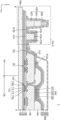
도 3은 도 1의 A-A' 선을 따라 취한 단면을 개략적으로 도시하는 단면도이다.
도 4는 본 발명의 다른 실시예에 관한 유기발광 디스플레이 장치의 단면을 개략적으로 도시하는 단면도이다.
도 5는 본 발명의 또 다른 실시예에 관한 유기발광 디스플레이 장치의 일부를 개략적으로 도시하는 단면도이다.
도 6은 본 발명의 또 다른 실시예에 관한 유기발광 디스플레이 장치의 일부를 개략적으로 도시하는 단면도이다.
도 7은 본 발명의 또 다른 실시예에 관한 유기발광 디스플레이 장치의 일부를 개략적으로 도시하는 단면도이다.
도 8은 본 발명의 또 다른 실시예에 관한 유기발광 디스플레이 장치의 일부를 개략적으로 도시하는 단면도이다.1 is a plan view schematically illustrating an organic light emitting display device according to an exemplary embodiment of the present invention.
FIG. 2 is an equivalent circuit diagram of any one pixel of the organic light emitting display device of FIG. 1 .
FIG. 3 is a cross-sectional view schematically illustrating a cross-section taken along line AA′ of FIG. 1 .
4 is a cross-sectional view schematically illustrating a cross-section of an organic light emitting display device according to another embodiment of the present invention.
5 is a cross-sectional view schematically illustrating a portion of an organic light emitting display device according to still another embodiment of the present invention.
6 is a cross-sectional view schematically illustrating a part of an organic light emitting display device according to still another embodiment of the present invention.
7 is a cross-sectional view schematically illustrating a portion of an organic light emitting display device according to still another embodiment of the present invention.
8 is a cross-sectional view schematically illustrating a portion of an organic light emitting display device according to still another embodiment of the present invention.
본 발명은 다양한 변환을 가할 수 있고 여러 가지 실시예를 가질 수 있는 바, 특정 실시예들을 도면에 예시하고 상세한 설명에 상세하게 설명하고자 한다. 본 발명의 효과 및 특징, 그리고 그것들을 달성하는 방법은 도면과 함께 상세하게 후술되어 있는 실시예들을 참조하면 명확해질 것이다. 그러나 본 발명은 이하에서 개시되는 실시예들에 한정되는 것이 아니라 다양한 형태로 구현될 수 있다. Since the present invention can apply various transformations and have various embodiments, specific embodiments will be illustrated in the drawings and described in detail in the detailed description. Effects and features of the present invention, and methods for achieving them will become clear with reference to the embodiments described later in detail together with the drawings. However, the present invention is not limited to the embodiments disclosed below and may be implemented in various forms.
이하, 첨부된 도면을 참조하여 본 발명의 실시예들을 상세히 설명하기로 하며, 도면을 참조하여 설명할 때 동일하거나 대응하는 구성 요소는 동일한 도면부호를 부여하고 이에 대한 중복되는 설명은 생략하기로 한다.Hereinafter, embodiments of the present invention will be described in detail with reference to the accompanying drawings, and when describing with reference to the drawings, the same or corresponding components are assigned the same reference numerals, and overlapping descriptions thereof will be omitted. .
이하의 실시예에서, 제1, 제2 등의 용어는 한정적인 의미가 아니라 하나의 구성 요소를 다른 구성 요소와 구별하는 목적으로 사용되었다. 또한, 단수의 표현은 문맥상 명백하게 다르게 뜻하지 않는 한, 복수의 표현을 포함한다.In the following embodiments, terms such as first and second are used for the purpose of distinguishing one component from another component without limiting meaning. Also, expressions in the singular number include plural expressions unless the context clearly dictates otherwise.
한편, 포함하다 또는 가지다 등의 용어는 명세서상에 기재된 특징, 또는 구성요소가 존재함을 의미하는 것이고, 하나 이상의 다른 특징들 또는 구성요소가 부가될 가능성을 미리 배제하는 것은 아니다. 또한, 막, 영역, 구성 요소 등의 부분이 다른 부분 "위에" 또는 "상에" 있다고 할 때, 다른 부분의 "바로 위에" 또는 "바로 상에" 있는 경우뿐만 아니라, 그 중간에 다른 막, 영역, 구성 요소 등이 개재되어 있는 경우도 포함한다. Meanwhile, terms such as include or have mean that features or elements described in the specification exist, and do not preclude the possibility that one or more other features or elements may be added. In addition, when a part such as a film, region, component, etc. is said to be "on" or "on" another part, not only when it is "directly on" or "on" another part, but also another film in the middle, A case where a region, component, etc. are interposed is also included.
도면에서는 설명의 편의를 위하여 구성 요소들이 그 크기가 과장 또는 축소될 수 있다. 예컨대, 도면에서 나타난 각 구성의 크기 및 두께는 설명의 편의를 위해 임의로 나타내었으므로, 본 발명이 반드시 도시된 바에 한정되지 않는다.In the drawings, the size of components may be exaggerated or reduced for convenience of explanation. For example, since the size and thickness of each component shown in the drawings are arbitrarily shown for convenience of description, the present invention is not necessarily limited to the illustrated bar.
x축, y축 및 z축은 직교 좌표계 상의 세 축으로 한정되지 않고, 이를 포함하는 넓은 의미로 해석될 수 있다. 예를 들어, x축, y축 및 z축은 서로 직교할 수도 있지만, 서로 직교하지 않는 서로 다른 방향을 지칭할 수도 있다.The x-axis, y-axis, and z-axis are not limited to the three axes of the Cartesian coordinate system, and may be interpreted in a broad sense including them. For example, the x-axis, y-axis, and z-axis may be orthogonal to each other, but may refer to different directions that are not orthogonal to each other.
어떤 실시예가 달리 구현 가능한 경우에 특정한 공정 순서는 설명되는 순서와 다르게 수행될 수도 있다. 예를 들어, 연속하여 설명되는 두 공정이 실질적으로 동시에 수행될 수도 있고, 설명되는 순서와 반대의 순서로 진행될 수 있다.When an embodiment is otherwise implementable, a specific process sequence may be performed differently from the described sequence. For example, two processes described in succession may be performed substantially simultaneously, or may be performed in an order reverse to the order described.
도 1은 본 발명의 일 실시예에 따른 유기발광 디스플레이 장치를 개략적으로 도시하는 평면도이고, 도 2는 도 1의 유기발광 디스플레이 장치의 어느 하나의 화소의 등가회로도이다.1 is a plan view schematically illustrating an organic light emitting display device according to an exemplary embodiment, and FIG. 2 is an equivalent circuit diagram of any one pixel of the organic light emitting display device of FIG. 1 .
도 1을 참조하면, 유기발광 디스플레이 장치(1)는 기판(100) 상에 배치된 디스플레이부(10)를 포함한다. 디스플레이부(10)는 y방향으로 연장된 스캔선(SL) 및 y방향과 교차하는 x방향으로 연장된 데이터선(DL)에 연결된 화소(P)들을 포함한다. 디스플레이부(10)는 화소(P)들에서 방출되는 빛을 통해 소정의 이미지를 제공하며, 디스플레이영역(DA)을 정의한다.Referring to FIG. 1 , an organic light
각 화소(P)는 예컨대, 적색, 녹색, 청색, 또는 백색의 빛을 방출할 수 있다. 각 화소(P)는 표시소자를 포함하며, 표시소자는 유기발광소자(organic light emitting diode)를 포함할 수 있다. 본 명세서에서의 화소(P)라 함은 전술한 바와 같이 적색, 녹색, 청색, 또는 백색 중 어느 하나의 색상의 빛을 방출하는 화소를 나타낸다.Each pixel P may emit red, green, blue, or white light, for example. Each pixel P includes a display element, and the display element may include an organic light emitting diode. As described above, the pixel P in the present specification refers to a pixel emitting light of any one color among red, green, blue, and white.
도 2를 참조하면, 화소(P)는 스캔선(SL) 및 데이터선(DL)에 연결된 화소회로(PC) 및 화소회로(PC)에 연결된 유기발광소자(OLED)를 포함할 수 있다. 화소회로(PC)는 구동 박막 트랜지스터(Td), 스위칭 박막 트랜지스터(Ts), 및 스토리지 커패시터(Cst)를 포함한다. 스위칭 박막 트랜지스터(Ts)는 스캔선(SL) 및 데이터선(DL)에 연결되며, 스캔선(SL)을 통해 입력되는 스캔 신호에 따라 데이터선(DL)을 통해 입력된 데이터 신호를 구동 박막 트랜지스터(Td)로 전달한다. Referring to FIG. 2 , a pixel P may include a pixel circuit PC connected to a scan line SL and a data line DL, and an organic light emitting diode OLED connected to the pixel circuit PC. The pixel circuit PC includes a driving thin film transistor Td, a switching thin film transistor Ts, and a storage capacitor Cst. The switching thin film transistor Ts is connected to the scan line SL and the data line DL, and drives the data signal input through the data line DL according to the scan signal input through the scan line SL. forward to (Td).
스토리지 커패시터(Cst)는 스위칭 박막 트랜지스터(Ts) 및 구동전압선(PL)에 연결되며, 스위칭 박막 트랜지스터(Ts)로부터 전달받은 전압과 구동전압선(PL)에 공급되는 구동전압(ELVDD)의 차이에 해당하는 전압을 저장한다.The storage capacitor Cst is connected to the switching thin film transistor Ts and the driving voltage line PL, and corresponds to a difference between the voltage received from the switching thin film transistor Ts and the driving voltage ELVDD supplied to the driving voltage line PL. store the voltage
구동 박막 트랜지스터(Td)는 구동전압선(PL)과 스토리지 커패시터(Cst)에 연결되며, 스토리지 커패시터(Cst)에 저장된 전압 값에 대응하여 구동전압선(PL)으로부터 유기발광소자(OLED)를 흐르는 구동 전류를 제어할 수 있다. 유기발광소자(OLED)는 구동 전류에 의해 소정의 휘도를 갖는 빛을 방출할 수 있다. 유기발광소자(OLED)는 예컨대, 적색, 녹색, 청색 또는 백색의 빛을 방출할 수 있다.The driving thin film transistor (Td) is connected to the driving voltage line (PL) and the storage capacitor (Cst), and the driving current flowing through the organic light emitting diode (OLED) from the driving voltage line (PL) in response to the voltage value stored in the storage capacitor (Cst). can control. The organic light emitting diode (OLED) may emit light having a predetermined luminance by a driving current. The organic light emitting diode (OLED) may emit, for example, red, green, blue, or white light.
도 2에서는 화소(P)가 2개의 박막 트랜지스터 및 1개의 스토리지 박막 트랜지스터를 포함하는 경우를 설명하였으나, 본 발명은 이에 한정되지 않는다. 다른 실시예로, 화소(P)의 화소회로(PC)는 3개 이상의 박막 트랜지스터를 포함하거나, 2개 이상의 스토리지 박막 트랜지스터를 포함하는 것과 같이 다양하게 변경될 수 있다.In FIG. 2 , the case where the pixel P includes two thin film transistors and one storage thin film transistor has been described, but the present invention is not limited thereto. In another embodiment, the pixel circuit PC of the pixel P may be variously changed, such as including three or more thin film transistors or two or more storage thin film transistors.
다시 도 1을 참조하면, 외곽영역(PA)은 디스플레이영역(DA)의 외측에 배치된다. 예컨대, 외곽영역(PA)은 디스플레이영역(DA)을 둘러쌀 수 있다. 외곽영역(PA)은 화소(P)들이 배치되지 않은 영역으로, 이미지를 제공하지 않는 비표시영역에 해당한다. Referring back to FIG. 1 , the outer area PA is disposed outside the display area DA. For example, the outer area PA may surround the display area DA. The outer area PA is an area where the pixels P are not disposed, and corresponds to a non-display area that does not provide an image.
외곽영역(PA)에는 구동회로(drive circuit), 예컨대 제1 및 제2 스캔 구동회로(20, 30), 패드부(40), 구동 전원공급배선(60), 및 공통 전원공급배선(70)이 배치될 수 있다.In the outer area PA, a drive circuit, for example, first and second
제1 및 제2 스캔 구동회로(20, 30)는 기판(100)의 외곽영역(PA) 상에 배치되며, 스캔선(SL)을 통해 각 화소(P)에 스캔 신호를 생성하여 전달한다. 일 예로, 제1 스캔 구동회로(20)는 디스플레이부(10)의 좌측에, 제2 스캔 구동회로(30)는 디스플레이부(10)의 우측에 배치될 수 있으나, 본 발명은 이에 제한되지 않는다. 다른 실시예로, 스캔 구동회로는 하나만 구비될 수 있다.The first and second
패드부(40)는 기판(100)의 일 단부에 배치되며, 복수의 패드(41, 42, 44, 45)를 포함한다. 패드부(40)는 절연층에 의해 덮이지 않고 노출되어, 플렉서블 인쇄회로기판(FPCB)과 전기적으로 연결될 수 있다. 패드부(40)는 제1 및 제2 스캔 구동회로(20, 30)이 위치하지 않은 기판(100)의 일 측에 배치될 수 있다.The
플렉서블 인쇄회로기판(FPCB)은 제어부(55)와 패드부(40)를 전기적으로 연결하며, 제어부(55)로부터 전달된 신호 또는 전원은 패드부(40)에 연결된 연결배선(21, 31, 51, 61, 71)들을 통해 이동한다.The flexible printed circuit board (FPCB) electrically connects the control unit 55 and the
제어부(55)는 수직동기신호, 수평동기신호, 및 클럭신호를 전달받아 제1 및 제2 스캔 구동회로(20, 30)의 구동을 제어하기 위한 제어 신호를 생성하고, 생성된 신호는 플렉서블 인쇄회로기판(FPCB)과 연결된 패드(44) 및 연결배선(21, 31)을 통해 제1 및 제2 스캔 구동회로(20, 30) 각각에 전달될 수 있고, 제1 및 제2 스캔 구동회로(20, 30)의 스캔 신호는 스캔선(SL)을 통해 각 화소(P)에 제공될 수 있다. 그리고, 제어부(55)는 플렉서블 인쇄회로기판(FPCB)과 연결된 패드(42, 45) 및 연결배선(61, 71)을 통해 구동 전원공급배선(60) 및 공통 전원공급배선(70) 각각에 구동전원(ELVDD) 및 공통전원(ELVSS)을 제공한다. 구동전원(ELVDD)은 구동전압선(PL)을 통해 각 화소(P)에 제공되고, 공통전원(ELVSS)은 화소(P)의 공통전극에 제공될 수 있다.The controller 55 receives the vertical synchronizing signal, the horizontal synchronizing signal, and the clock signal and generates a control signal for controlling driving of the first and second
플렉서블 인쇄회로기판(FPCB)에는 데이터 구동회로(50)가 배치될 수 있다. 데이터 구동회로(50)는 데이터 신호를 각 화소(P)에 제공한다. 데이터 구동회로(50)의 데이터 신호는 패드(41)에 연결된 연결배선(51) 및 연결배선(51)과 연결된 데이터선(DL)을 통해 각 화소(P)에 제공된다. 도 1에서는 데이터 구동회로(50)가 플렉서블 인쇄회로기판(FPCB) 상에 배치된 것을 도시하였으나, 본 발명은 이에 한정되지 않는다. 다른 실시예로, 데이터 구동회로(50)는 기판(100)의 외곽영역(PA) 상에 배치될 수 있다. The
구동 전원공급배선(60)은 외곽영역(PA) 상에 배치될 수 있다. 예컨대, 구동 전원공급배선(60)은 패드부(40)와 인접한 디스플레이부(10)의 일측과 패드부(40) 사이에 배치될 수 있다. 패드(41)와 연결된 연결배선(61)을 통해 제공된 구동전원(ELVDD)은 구동전압선(PL)을 통해 각 화소(P)들에 제공될 수 있다.The driving
공통 전원공급배선(70)은 외곽영역(PA) 상에 배치되며, 디스플레이부(10)를 부분적으로 둘러쌀 수 있다. 예컨대, 공통 전원공급배선(70)은 패드부(40)와 인접한 디스플레이부(10)의 일측이 개방된 루프 형태로서, 패드부(40)를 제외한 기판(100)의 가장자리(100e)를 따라 연장될 수 있다.The common
도 1의 공통 전원공급배선(70)은 패드(45)와 연결된 연결배선(71)에 전기적으로 연결되며, 화소(P)의 유기발광소자의 대향전극(230)(예컨대, 캐소드)에 공통전원(ELVSS)을 제공한다. 도 1에서는 공통 전원공급배선(70)이 디스플레이부(10)를 부분적으로 둘러싸는 일측이 개방된 루프 형태이며, 연결배선(71)과 일부 중첩하는 것을 도시하고 있다. 연결배선(71)과 공통 전원공급배선(70)은 이들 사이에 개재되는 절연층, 예컨대 무기 절연층의 콘택홀(CNT)을 통해 접속될 수 있으며, 연결배선(71)과 공통 전원공급배선(70)의 접속영역, 즉 콘택홀(CNT)은 패드부(40)를 향하는 디스플레이부(10)의 일측과 인접한 영역일 수 있다. 다른 실시예로, 연결배선(71)을 별도로 구비하지 않고, 공통 전원공급배선(70)이 패드(45)와 직접 연결될 수도 있다.The common
한편 디스플레이부(10) 상부에는 디스플레이부(10)를 외부로부터 밀봉하는 박막봉지부(80)가 더 구비될 수 있다. 박막봉지부(80)는 무기막과 유기막(320)이 교번하여 적층된 다층막으로 구비될 수 있다. 박막봉지부(80)는 디스플레이부(10)를 비롯하여 외곽영역(PA)에 배치된 회로부들(예컨대, 제1 및 제2 스캔 구동회로(20, 30) 및 공통 전원공급배선(70))을 덮고 기판(100)의 가장자리(100e)까지 연장되도록 배치될 수 있다.Meanwhile, a thin
공통 전원공급배선(70) 외측에는 댐부(90)가 위치할 수 있다. 본 실시예에서 댐부(90)는 제1 댐부(92) 및 제2 댐부(94)를 포함할 수 있다. 제1 댐부(92)는 상대적으로 공통 전원공급배선(70)에 인접하여 배치되고, 제2 댐부(94)는 제1 댐부(92) 외곽을 둘러 배치된다. 박막봉지부(80)는 제1 댐부(92) 및 제2 댐부(94)를 모두 커버하도록 구비될 수 있다.A
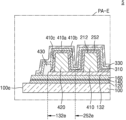
도 3은 도 1의 A-A' 선을 따라 취한 단면을 개략적으로 도시하는 단면도이고, 도 4는 본 발명의 다른 실시예에 관한 유기발광 디스플레이 장치의 단면을 개략적으로 도시하는 단면도이다.FIG. 3 is a cross-sectional view schematically illustrating a cross-section taken along line AA′ of FIG. 1 , and FIG. 4 is a cross-sectional view schematically illustrating a cross-section of an organic light emitting display device according to another exemplary embodiment of the present invention.
도 4는 도 3과 같이 A-A' 선을 따라 취한 단면을 도시하나, 광개선층(250)의 구조에서 도 3의 실시예와 차이가 있다. 이를 제외한 다른 구성은 도 3의 실시예와 동일한바, 중복되는 부분은 이하 설명에서 원용한다.4 shows a cross section taken along the line A-A' as in FIG. 3, but there is a difference from the embodiment of FIG. 3 in the structure of the
도 3을 참조하면, 유기발광 디스플레이 장치(1)는 디스플레이영역(DA)과 외곽영역(PA)을 구비한다. 기판(100)은 글라스재, 금속재, 또는 PET(Polyethylen terephthalate), PEN(Polyethylen naphthalate), 폴리이미드(Polyimide) 등과 같은 플라스틱재 등, 다양한 재료로 형성된 것일 수 있다.Referring to FIG. 3 , the organic light emitting
도 3의 디스플레이영역(DA)을 참조하면, 디스플레이영역(DA) 상에는 디스플레이부가 위치할 수 있다. 디스플레이부는 대략 디스플레이영역(DA)에 배치된 각종 층들, 배선들 및 소자들을 의미할 수 있다.Referring to the display area DA of FIG. 3 , a display unit may be positioned on the display area DA. The display unit may roughly refer to various layers, wires, and elements disposed in the display area DA.
기판(100) 상에 버퍼층(120)이 위치할 수 있다. 버퍼층(120)은 기판(100)을 통하여 침투하는 이물 또는 습기를 차단할 수 있다. 예를 들어, 버퍼층(120)은 산화규소(SiOx), 질화규소(SiNx) 또는/및 산질화규소(SiON)와 같은 무기물을 포함할 수 있으며, 단층 또는 다층으로 형성될 수 있다.A
박막트랜지스터(110)는 반도체층(112) 및 게이트전극(114)을 포함한다. 반도체층(112)은 예컨대 폴리실리콘을 포함할 수 있다. 반도체층(112)은 게이트전극(114)과 중첩하는 채널영역 및 채널영역의 양측에 배치되되 채널영역보다 고농도의 불순물을 포함하는 소스영역 및 드레인영역을 포함할 수 있다. 여기서, 불순물은 N형 불순물 또는 P형 불순물을 포함할 수 있다. 소스영역과 드레인영역은 박막트랜지스터(110)의 소스전극(116s) 및/또는 드레인전극(116d)와 전기적으로 연결될 수 있다.The
본 실시예에서 반도체층(112)은 폴리실리콘을 함유하는 경우를 설명하였으나, 본 발명은 이에 한정하지 않는다. 다른 실시예로, 반도체층(112)은 아모퍼스 실리콘을 포함하거나, 유기 반도체물질을 포함할 수 있다.In this embodiment, the case where the
반도체층(112)과 게이트전극(114) 사이에는 게이트절연막(140)이 배치될 수 있다. 게이트절연막(140)은 산질화규소(SiON), 산화규소(SiOx) 및/또는 질화규소(SiNx)와 같은 무기 절연층일 수 있으며, 무기 절연층은 단층 또는 다층일 수 있다.A
또한, 게이트전극(114)과 소스전극(116s) 및/또는 드레인전극(116d) 사이에는 층간절연막(160)이 배치될 수 있다. 층간절연막(160)은 예컨대 유기절연물 또는 무기절연물을 포함할 수 있다. 유기절연물은 폴리이미드와 같은 이미드계 고분자, Polymethylmethacrylate(PMMA)나, Polystylene(PS)과 같은 일반 범용고분자, 페놀계 그룹을 갖는 고분자 유도체, 아크릴계 고분자, 아릴에테르계 고분자, 아마이드계 고분자, 불소계고분자, p-자일렌계 고분자, 비닐알콜계 고분자 및 이들의 블렌드 등일 수 있다. 무기절연물은 산질화규소(SiON), 산화규소(SiOx) 및/또는 질화규소(SiNx)일 수 있다. 이러한 층간절연막(160)은 단층 또는 다층으로 형성될 수 있다.In addition, an
박막트랜지스터 상에는 유기 절연층(180)이 배치될 수 있다. 유기 절연층(180)은 박막트랜지스터를 보호하고, 박막트랜지스터의 상부를 평탄화하게 할 수 있다. 유기 절연층(180)은 이미드계 고분자, Polymethylmethacrylate(PMMA)나, Polystylene(PS)과 같은 일반 범용고분자, 페놀계 그룹을 갖는 고분자 유도체, 아크릴계 고분자, 아릴에테르계 고분자, 아마이드계 고분자, 불소계고분자, p-자일렌계 고분자, 비닐알콜계 고분자 및 이들의 블렌드 등을 포함할 수 있다.An organic insulating
유기 절연층(180) 상에는 유기발광소자(200)가 배치된다. 유기발광소자(200)는 화소전극(210), 대향전극(230) 및 화소전극(210)과 대향전극(230) 사이에 배치된 중간층(220)을 포함할 수 있다.The organic
화소전극(210) 상에는 화소정의막(240)이 배치되며, 화소정의막(240)은 각 부화소에 대응하는 개구, 즉 적어도 화소전극(210)의 중앙부가 노출되도록 하는 개구를 가짐으로써 화소를 정의할 수 있다. 또한, 화소정의막(240)은 화소전극(210)의 가장자리와 대향전극(230) 사이의 거리를 증가시킴으로써, 이들 사이에서 아크 등이 발생하는 것을 방지할 수 있다. 화소정의막(240)은 예컨대 폴리이미드 또는 HMDSO(hexamethyldisiloxane) 등과 같은 유기물로 형성될 수 있다.A pixel-defining
한편, 다른 실시예로, 화소정의막(240) 상에는 스페이서(미도시)가 더 배치될 수도 있다.Meanwhile, in another embodiment, spacers (not shown) may be further disposed on the
화소전극(210)(220)은 (반)투명 전극 또는 반사형 전극으로 형성될 수 있다. (반)투명 전극으로 형성될 때에는 예컨대 ITO, IZO, ZnO, In2O3, IGO 또는 AZO로 형성될 수 있다. 반사형 전극으로 형성될 때에는 Ag, Mg, Al, Pt, Pd, Au, Ni, Nd, Ir, Cr 및 이들의 화합물 등으로 형성된 반사막과, ITO, IZO, ZnO, In2O3, IGO 또는 AZO로 형성된 층을 가질 수 있다. 물론 본 발명이 이에 한정되는 것은 아니고 다양한 재질로 형성될 수 있으며, 그 구조 또한 단층 또는 다층이 될 수 있는 등 다양한 변형이 가능하다.The
중간층(220)이 고분자 물질을 포함할 경우에는, 중간층(220)은 대개 홀 수송층(HTL) 및 발광층(EML)을 포함하는 구조를 가질 수 있다. 이 때, 홀 수송층은 PEDOT을 포함하고, 발광층은 PPV(Poly-Phenylenevinylene)계 및 폴리플루오렌(Polyfluorene)계 등 고분자 물질을 포함할 수 있다. 중간층(220)의 구조는 전술한 바에 한정되는 것은 아니고, 다양한 구조를 가질 수 있다. 예컨대, 중간층(220)을 이루는 층들 중 적어도 어느 하나는 복수개의 화소전극(210)들에 걸쳐서 일체(一體)로 형성될 수 있다. 또는, 중간층(220)은 복수개의 화소전극(210)들 각각에 대응하도록 패터닝된 층을 포함할 수 있다.When the
대향전극(230)은 디스플레이영역(DA) 상부에 배치되며, 디스플레이영역(DA) 전면에 걸쳐 배치될 수 있다. 즉, 대향전극(230)은 복수개의 화소들을 커버하도록 일체(一體)로 형성될 수 있다.The
대향전극(230)이 (반)투명 전극으로 형성될 때에는 일함수가 작은 금속 즉, Li, Ca, LiF/Ca, LiF/Al, Al, Ag, Mg 및 이들의 화합물로 형성된 층과 ITO, IZO, ZnO 또는 In2O3 등의 (반)투명 도전층을 가질 수 있다. 대향전극(230)이 반사형 전극으로 형성될 때에는 Li, Ca, LiF/Ca, LiF/Al, Al, Ag, Mg 및 이들의 화합물로 형성된 층을 가질 수 있다. 물론 대향전극(230)의 구성 및 재료가 이에 한정되는 것은 아니며 다양한 변형이 가능함은 물론이다.When the
대향전극(230) 상에는 박막봉지부(300)가 배치될 수 있다. 본 실시예에 관한 박막봉지부(300)는 제1 무기막(310), 제2 무기막(330) 및 제1 무기막(310)과 제2 무기막(330) 사이에 개재된 유기막(320)을 포함할 수 있다. 유기막(320)은 제1 무기막(310)과 제2 무기막(330)에 의해 밀봉될 수 있으며, 디스플레이영역(DA) 및 디스플레이영역(DA)에 인접한 외곽영역(PA)의 일부에 걸쳐 배치될 수 있다. 본 실시예에서 유기막(320)은 유기 절연층(180) 상에 배치되나, 본 발명이 반드시 이에 한정되는 것은 아니다.A thin
박막봉지부(300)의 유기막(320)은 예컨대, 아크릴계 수지, 메타크릴계 수지, 폴리이소프렌, 비닐계 수지, 에폭시계 수지, 우레탄계 수지, 셀룰로오스계 수지 또는 페릴렌계 수지를 포함할 수 있다. 구체적으로 유기막(320)은 부틸아그릴레이트, 에틸헥실아크릴레이트, 프로필렌글리콜메타크릴레이트, 테트라하이드로퍼프리 메타크릴레이트, 비닐아세테이트, N-비닐피롤리돈, 싸이클로알리파틱 에폭사이드, 에폭시 아크릴레이트, 비닐 에폭시계 수지, 우레탄 아크릴레이트, 셀룰로오즈나이트레이트 등을 포함할 수 있다.The
박막봉지부(300)의 제1 무기막(310) 및 제2 무기막(330)은 예컨대, 실리콘 질화물, 알루미늄 질화물, 지르코늄 질화물, 티타늄 질화물, 하프늄 질화물, 탄탈륨 질화물, 실리콘 산화물, 알루미늄 산화물, 티타늄 산화물, 주석 산화물, 세륨 산화물 또는 실리콘 산화질화물(SiON)을 포함할 수 있다.The first
한편, 대향전극(230)과 박막봉지부(300) 사이에는 광개선층(250)이 개재될 수 있다. 광개선층(250)은 예컨대, 저굴절층일 수 있다. 광개선층(250)은 유기발광소자(200)로부터 발생된 빛이 효율적으로 외부로 방출될 수 있도록 하며, 플라즈마 등을 이용한 후속 공정 과정에서 발생할 수 있는 손상으로부터 유기발광 소자(200)를 보호하는 기능을 할 수 있다. 이러한 광개선층(250)은 예컨대, 불화리튬(LiF; lithium fluoride)을 포함할 수 있다. 개선층은 디스플레이영역(DA) 상에 위치할 수 있다. Meanwhile, an
광개선층(250)은 도 3과 같이 대향전극(230) 상에 위치할 수 있다. 또한, 광개선층(250)은 도 4와 같이 제1 댐부(410)까지 연장되어 구비될 수도 있다. 도 3의 실시예와 같은 경우는 광개선층(250)이 형성되는 과정에서 증착마스크의 오픈부에만 이상적(ideal)으로 형성되는 경우이다. 한편, 도 4의 실시예와 같이 광개선층(250)이 제1 댐부(410)까지 연장되어 형성되는 경우는 제조과정에서 광개선층(250)의 일부가 '쉐도우(Shadow)막'으로 형성되는 경우이다.The
광개선층(250)은 마스크를 이용한 증착 방식을 통해 형성될 수 있다. 이 경우 마스크와 기판(100) 사이의 이격 거리로 이하여 마스크의 오픈부 이외에 광개선층(250)의 잔막이 형성되게 된다. 이와 같이 마스크의 오픈부 이외에 형성되는 광개선층(250)의 일부를 일명 '쉐도우막'으로 정의할 수 있다. 이러한 '쉐도우막'은 기판(100) 하부에 위치한 쿨 플레이트(Cool plate)와 기판(100) 상부에 위치한 마스크 사이에 자력을 이용하여 기판(100)과 마스크 사이의 이격 거리를 제어하는 방식으로 형성되므로, 공정 상 '쉐도우막'의 형성은 불가피하다. 경우에 따라 도 4와 같이 '쉐도우막'은 제1 댐부(410)까지 확장되는 경우가 있고, 특히 물리적으로 매우 취약한 부분인 제1 댐부(410) 상에 '쉐도우막'이 형성되는 경우에는 유기물과의 접착력(adhesion)이 약한 광개선층(250)과 제1 댐부(410) 사이에 막 들뜸 현상이 발생하는 문제점이 있다.The
상기 문제점들을 해결하기 위하여, 본 발명의 일 실시예에 따른 유기발광 디스플레이 장치에서는 접착력이 약한 광개선층(250)과 제1 댐부(410) 사이에 금속층(212)을 개재하여 제1 댐부(410) 영역에서 접착력을 향상시킴으로써 광개선층(250)과 제1 댐부(410) 사이의 막 들뜸 현상을 효과적으로 감소시킬 수 있다. 즉, 제1 댐부(410)와 광개선층(250)이 서로 직접 접촉하는 경우의 접착력에 비해, 제1 댐부(410)와 금속층(212)과의 접착력 및 광개선층(250)과 금속층(212)과의 접착력이 더 우수하다. 금속층(212)에 대하여는 자세히 후술한다.In order to solve the above problems, in the organic light emitting display device according to an embodiment of the present invention, a
한편, 도 3의 외곽영역(PA)을 참조하면 디스플레이영역(DA)과 인접한 순으로 구동회로(DC), 전원공급라인(130), 제1 댐부(410) 및 제2 댐부(420)가 위치할 수 있다. 구동회로(DC)는 도 1의 제1, 2 스캔 구동회로(20, 30)에 대응되고, 전원공급라인(130)은 도 1의 공통 전원공급배선(70)에 대응된다. 구동회로(DC) 및 전원공급라인(130)은 도 1에 도시된 것과 같이 디스플레이부의 일부를 둘러싸도록 배치될 수 있다. 전원공급라인(130)은 금속층(212)을 통해 대향전극(230)과 전기적으로 연결됨으로써 디스플레이부에 공통 전원을 공급할 수 있다.On the other hand, referring to the outer area PA of FIG. 3, the driving circuit DC, the
도 3의 최외곽영역(PA-E)을 참조하면, 제1 댐부(410) 및 제2 댐부(420)는 구동회로(DC)의 외측에 배치될 수 있다. 제1 댐부(410) 및 제2 댐부(420)는 도 1에 도시된 것과 같이 디스플레이부의 주변을 둘러싸도록 배치될 수 있다. 이러한 제1 댐부(410) 및 제2 댐부(420)를 통해 박막봉지부(300)를 구성하는 유기막(320)이 오버플로우(overflow)되는 것을 방지할 수 있다.Referring to the outermost area PA-E of FIG. 3 , the
제1 댐부(410)는 유기 절연층(180)과 동일물질을 포함할 수 있다. 예컨대, 제1 댐부(410)는 이미드계 고분자, Polymethylmethacrylate(PMMA)나, Polystylene(PS)과 같은 일반 범용고분자, 페놀계 그룹을 갖는 고분자 유도체, 아크릴계 고분자, 아릴에테르계 고분자, 아마이드계 고분자, 불소계고분자, p-자일렌계 고분자, 비닐알콜계 고분자 및 이들의 블렌드 등을 포함할 수 있다.The
제1 댐부(410) 상에는 금속층(212)이 배치될 수 있다. 금속층(212)은 제1 댐부(410)의 상면(410a), 내측면(410b) 및 외측면(410c)을 덮으며 이들과 직접 접촉하도록 바로 상에 배치될 수 있다. 금속층(212)의 일단부(212a)는 유기 절연층(180) 상에 위치하여 유기 절연층(180)의 끝 단을 덮도록 구비되며, 금속층(212)의 타단부(212b)는 제2 댐부(420)까지 연장되도록 배치될 수 있다.A
이러한 금속층(212)은 화소전극(210)과 동일물질을 포함하도록 형성될 수 있다. 예컨대, 금속층(212)은 ITO, IZO, ZnO, In2O3, IGO 또는 AZO로 형성될 수 있다. 또는 Ag, Mg, Al, Pt, Pd, Au, Ni, Nd, Ir, Cr 및 이들의 화합물 등으로 형성된 층과, ITO, IZO, ZnO, In2O3, IGO 또는 AZO로 형성된 층의 다층 구조를 가질 수 있다.The
제2 댐부(420)는 제1 댐부(410) 보다 더 높은 다층 구조로 형성될 수 있다. 본 실시예에서 제2 댐부(420)는 제1 층(422), 제2 층(424) 및 제3 층(426)을 포함할 수 있다. 제1 층(422)은 유기 절연층(180)과 동일물질을 포함하고, 제2 층(424)은 화소정의막(240)과 동일물질을 포함할 수 있다. 제3 층(426)은 도 3에 도시되어 있지는 않으나, 화소정의막(240) 상부에 위치한 스페이서(미도시)와 동일물질을 포함할 수 있다.The
도 3의 제2 댐부(420)는 제1 층(422), 제2 층(424) 및 제3 층(426)으로 구비되나, 다른 실시예로서 제3 층(426)을 제외하고 제1 층(422) 및 제2 층(424)으로만 구비될 수도 있다.The
박막봉지부(300)의 제1 무기막(310) 및 제2 무기막(330)은 제2 댐부(420)까지 연장되도록 구비될 수 있다. 제1 무기막(310) 및 제2 무기막(330)은 제1 댐부(410) 및 제2 댐부(420)를 덮으며 기판(100)의 가장자리(100e)까지 연장될 수 있다. 제1 무기막(310) 및 제2 무기막(330)이 기판(100)의 가장자리(100e)까지 연장됨으로써 밀봉력을 극대화시킬 수 있다.The first
도 4를 참조하면, 도 4의 실시예는 전술한 것과 같이 도 3의 실시예와 광개선층(250)의 구조를 제외하고 동일하다. 도 4의 경우는 광개선층(250)의 일부가 '쉐도우막'을 포함하여 형성되는 경우를 도시한다. 이하에서는 '쉐도우막' 부분을 무기 물질층(252)로 정의하여 설명한다.Referring to FIG. 4 , the embodiment of FIG. 4 is the same as the embodiment of FIG. 3 except for the structure of the
도 4에서 최외곽영역(PA-E)을 포함하는 외곽영역(PA)을 참조하면, 무기 물질층(252)은 제조과정에서 광개선층(250)을 형성하는 마스크 패턴 외곽에 형성된 부분으로, 광개선층(250)을 형성하는 증착물질의 일부가 마스크와 기판(100)의 이격 공간으로 퍼져나가 형성된 부분으로 이해될 수 있다. 따라서, 무기 물질층(252)은 광개선층(250)과 일체(一體)로 구비될 수 있으며, 광개선층(250)의 단부로 이해될 수 있다. 광개선층(250)과 무기 물질층(252) 영역은 명확히 구분되는 것은 아니나, 광개선층(250)의 역할이 디스플레이부에서 발광하는 광 기능을 개선하는 것에 있는바, 광개선층(250)은 디스플레이영역 상에 위치한 부분으로, 무기 물질층(252)은 외곽영역 상에 위치한 부분으로 이해될 수 있다.Referring to the outer area PA including the outermost area PA-E in FIG. 4 , the
광개선층(250)은 제1 두께를 갖고, 무기 물질층(252)은 제2 두께를 가질 수 있다. 이때 광개선층(250)의 제1 두께가 무기 물질층(252)의 제2 두께보다 두꺼울 수 있다. 이는 상술한 것과 같이, 무기 물질층(252)은 광개선층(250)을 형성하는 증착물질의 일부가 마스크와 기판(100)의 이격 공간으로 퍼져나가 형성된 부분으로 정의되므로, 광개선층(250)의 두께보다 무기 물질층(252)의 두께가 더 얇게 형성되는 것이다.The
또한, 무기 물질층(252)은 끝단(252e)으로 갈수록 점차적으로 얇아지는 두께를 가질 수 있다. 무기 물질층(252)은 끝단(252e)은 별도의 측면을 구비하지 않으며, 끝단(252e)으로 갈수록 점점 얇은 두께로 형성되다가 '특정 위치'가 되면 무기 물질층(252)은 더 이상 형성되지 않게 된다. 상기 '특정 위치'라 함은 명확히 정해진 것은 아니나, 현재 제조 공정 설계 하에서는 제1 댐부(410)를 덮는 위치까지 형성되는 것으로 정의될 수 있다.In addition, the
제1 댐부(410) 상부에는 금속층(212), 무기 물질층(252), 박막봉지부(300)의 제1 무기막(310) 및 제2 무기막(330)이 순차적으로 적층될 수 있다. 금속층(212)은 제1 댐부(410) 바로 상에 배치되어, 제1 댐부(410)의 상면, 내측면 및 외측면과 직접 면접촉할 수 있다. 금속층(212) 상에는 무기 물질층(252)이 배치될 수 있다. 이와 같이 금속층(212)이 유기물을 포함하는 제1 댐부(410) 및 무기물을 포함하는 무기 물질층(252) 사이에 직접 개재됨으로써, 제1 댐부(410)와 무기 물질층(252) 사이의 접착력을 효과적으로 개선시킬 수 있다.The
도 5는 본 발명의 또 다른 실시예에 관한 유기발광 디스플레이 장치의 일부를 개략적으로 도시하는 단면도이다. 도 5에서는 최외곽영역(PA-E)의 구조에서 전술한 도 3 및 도 4의 실시예와 차이가 있다.5 is a cross-sectional view schematically illustrating a portion of an organic light emitting display device according to still another embodiment of the present invention. In FIG. 5, there is a difference from the embodiments of FIGS. 3 and 4 in the structure of the outermost area PA-E.
도 5를 참조하면, 버퍼층(120), 게이트절연막(140), 층간절연막(160)은 최외곽영역(PA-E)까지 연장되어 배치될 수 있다. 이들 상부에는 제1 댐부(410) 및 제1 층 내지 제3층(422, 424, 426)을 포함하는 제2 댐부(420)가 배치되고, 박막봉지부(300)의 제1 무기막(310) 및 제2 무기막(330)은 제1 댐부(410) 및 제2 댐부(420)를 덮도록 기판(100)의 가장자리(100e)까지 연장될 수 있다.Referring to FIG. 5 , the
한편 본 실시예에서는, 제1 댐부(410) 하부에 제1 단차보상층(132)이 위치할 수 있다. 제1 단차보상층(132)은 도 4에서 전원공급라인(130)과 동일층에 배치되며 동일물질을 포함할 수 있다. 제1 단차보상층(132)은 전원공급라인(130)이 연장된 일부일 수도 있고, 별도로 구비된 층일 수도 있다. 제1 단차보상층(132)을 제1 댐부(410) 하부에 배치함으로써 제1 댐부(410)의 높이를 보전할 수 있다.Meanwhile, in this embodiment, the first
제1 댐부(410) 상에는 금속층(212)이 배치되고, 전술한 것과 같이 금속층(212)은 제1 댐부(410)와 무기 물질층(252) 사이의 접착력을 개선시키는 역할을 하므로, 화소전극(210)과 동일물질로 형성되는 금속층(212) 상에는 추가적으로 층을 형성하는 것이 용이하지 않다. 따라서, 제1 댐부(410)의 부족한 단차를 보완하고자, 제1 댐부(410) 하부에 제1 단차보상층(132)을 배치하여 제1 댐부(410)의 높이를 보전할 수 있다.A
도 5의 제1 단차보상층(132)은 제2 댐부(420)까지 연장되어 제1 단차보상층(132)의 끝단(130e)은 제2 댐부(420)에 의해 커버된다. 다만, 본 발명이 반드시 이에 한정되는 것은 아니며 제1 단차보상층(132)은 제1 댐부(410)의 단차를 보전하는 정도이면 족하다.The first
도 6은 본 발명의 또 다른 실시예에 관한 유기발광 디스플레이 장치의 일부를 개략적으로 도시하는 단면도이다. 도 6에서는 최외곽영역(PA-E)의 구조에서 전술한 도 3 및 도 4의 실시예와 차이가 있다.6 is a cross-sectional view schematically illustrating a part of an organic light emitting display device according to still another embodiment of the present invention. 6 differs from the embodiments of FIGS. 3 and 4 in the structure of the outermost area PA-E.
도 6을 참조하면, 버퍼층(120), 게이트절연막(140), 층간절연막(160)은 최외곽영역(PA-E)까지 연장되어 배치될 수 있다. 이들 상부에는 제1 댐부(410) 및 제1 층 내지 제3층(422, 424, 426)을 포함하는 제2 댐부(420)가 배치되고, 박막봉지부(300)의 제1 무기막(310) 및 제2 무기막(330)은 제1 댐부(410) 및 제2 댐부(420)를 덮도록 기판(100)의 가장자리(100e)까지 연장될 수 있다.Referring to FIG. 6 , the
한편 본 실시예에서는, 제1 댐부(410) 하부에 제1 단차보상층(132)(132) 및 제2 단차보상층(134)(134)이 위치할 수 있다. 제1 단차보상층(132)은 도 3 또는 도 4의 전원공급라인(130)과 동일물질을 포함할 수 있다. 제1 단차보상층(132)은 전원공급라인(130)이 연장된 일부일 수도 있고, 별도로 구비된 층일 수도 있다. 제2 단차보상층(134)은 도 3 또는 도 4의 박막트랜지스터(110)의 게이트전극(114)과 동일물질을 포함할 수 있다. 제1 단차보상층(132) 및 제2 단차보상층(134)을 제1 댐부(410) 하부에 배치함으로써 제1 댐부(410)의 높이를 보전할 수 있다.Meanwhile, in this embodiment, the first
도 7은 본 발명의 또 다른 실시예에 관한 유기발광 디스플레이 장치의 일부를 개략적으로 도시하는 단면도이다. 도 7에서는 최외곽영역(PA-E)의 구조에서 전술한 도 3 및 도 4의 실시예와 차이가 있다.7 is a cross-sectional view schematically illustrating a portion of an organic light emitting display device according to still another embodiment of the present invention. In FIG. 7, there is a difference from the embodiments of FIGS. 3 and 4 in the structure of the outermost area PA-E.
도 7을 참조하면, 버퍼층(120), 게이트절연막(140), 층간절연막(160)은 최외곽영역(PA-E)까지 연장되어 배치될 수 있다. 이들 상부에는 제1 댐부(410) 및 제2 댐부(420)가 배치되고, 박막봉지부(300)의 제1 무기막(310) 및 제2 무기막(330)은 제1 댐부(410) 및 제2 댐부(420)를 덮도록 기판(100)의 가장자리(100e)까지 연장될 수 있다.Referring to FIG. 7 , the
한편 본 실시예에서는, 제1 댐부(410)와 제2 댐부(420)는 동일한 높이로 구비될 수 있다. 제1 댐부(410)와 제2 댐부(420)가 동일한 높이로 구비된다는 것은, 제2 댐부(420)가 전술한 도 6에서 제1 층(422)만을 구비하고 있는 것으로 이해될 수 있다.Meanwhile, in this embodiment, the
금속층(212)은 제1 댐부(410)를 덮고 제2 댐부(420)까지 연장되어 배치될 수 있다. 즉, 금속층(212)은 제2 댐부(420)의 상면(420a), 내측면(420b) 및 외측면(420c)을 모두 커버하도록 구비될 수 있다. The
제1 댐부(410) 및 제2 댐부(420) 하부에는 제1 단차보상층(132)이 배치될 수 있다. 제1 단차보상층(132)은 도 3 또는 도 4의 전원공급라인(130)과 동일물질을 포함할 수 있다. 제1 단차보상층(132)은 전원공급라인(130)이 연장된 일부일 수도 있고, 별도로 구비된 층일 수도 있다. 제1 단차보상층(132)을 제1 댐부(410) 및 제2 댐부(420) 하부에 배치함으로써 제1 댐부(410) 및 제2 댐부(420)의 높이를 보전할 수 있다.A first
도 7의 제1 단차보상층(132)의 끝단(132e)은 제2 댐부(420) 외측으로 연장되며, 절연막(430)에 의해 제1 단차보상층(132)의 끝단(132e)이 커버될 수 있다.The
도시되어 있지는 않으나, 도 7의 제1 댐부(410) 및 제2 댐부(420) 하부에는 도 6의 실시예와 같이 제2 단차보상층(134)이 더 배치될 수도 있다.Although not shown, a second
도 8은 본 발명의 또 다른 실시예에 관한 유기발광 디스플레이 장치의 일부를 개략적으로 도시하는 단면도이다. 한편, 도 8에서는 제1 댐부(410) 및 제2 댐부(420) 하부에 제3 단차보상층(136)이 더 배치되는 것에서, 전술한 도 7의 실시예와 차이가 있다.8 is a cross-sectional view schematically illustrating a portion of an organic light emitting display device according to still another embodiment of the present invention. Meanwhile, in FIG. 8 , the third
도 8을 참조하면, 제1 댐부(410) 및 제2 댐부(420)의 하부에는 제3 단차보상층(136)이 더 배치될 수 있다. 제3 단차보상층(136)은 제1 단차보상층(132) 하부에 위치할 수 있다. 제3 단차보상층(136)은 유기물을 포함하는 유기 절연막일 수 있다.Referring to FIG. 8 , a third
본 발명은 도면에 도시된 실시예를 참고로 설명되었으나 이는 예시적인 것에 불과하며, 당해 기술분야에서 통상의 지식을 가진 자라면 이로부터 다양한 변형 및 균등한 다른 실시예가 가능하다는 점을 이해할 것이다. 따라서 본 발명의 진정한 기술적 보호 범위는 첨부된 특허청구범위의 기술적 사상에 의하여 정해져야 할 것 이다. Although the present invention has been described with reference to the embodiments shown in the drawings, this is merely exemplary, and those skilled in the art will understand that various modifications and equivalent other embodiments are possible therefrom. Therefore, the true technical protection scope of the present invention should be determined by the technical spirit of the appended claims.
1, 2, 3, 4, 5, 6: 유기발광 디스플레이 장치
10: 디스플레이부
20, 30: 스캔 구동회로
40: 패드부
60: 구동 전원공급배선
70: 공통 전원공급배선
80: 박막봉지부
90: 댐부
100: 기판
110: 박막트랜지스터
130: 전원공급라인
132: 제1 단차보상층
134: 제2 단차보상층
136: 제3 단차보상층
180: 유기 절연층
200: 유기발광소자
212: 금속층
240: 화소정의막
250: 광개선층
252: 무기 물질층
300: 박막봉지부
410: 제1 댐부
420: 제2 댐부1, 2, 3, 4, 5, 6: organic light emitting display device
10: display unit
20, 30: scan driving circuit
40: pad part
60: driving power supply wiring
70: common power supply wiring
80: thin film encapsulation
90: dam part
100: substrate
110: thin film transistor
130: power supply line
132: first step compensation layer
134: second step compensation layer
136: third step compensation layer
180: organic insulating layer
200: organic light emitting device
212: metal layer
240: pixel defining layer
250: light improvement layer
252: inorganic material layer
300: thin film encapsulation
410: first dam part
420: second dam part
Claims (20)
상기 기판의 상기 디스플레이영역 상에 배치되고, 박막트랜지스터 및 상기 박막트랜지스터를 덮도록 상부에 위치하는 유기 절연층을 포함하는, 박막트랜지스터부;
상기 박막트랜지스터와 전기적으로 연결되는 화소전극, 상기 화소전극 상에 배치되는 발광층, 상기 발광층을 사이에 두고 상기 화소전극과 대향하여 배치되는 대향전극을 포함하는, 유기발광소자;
상기 유기 절연층 상에 위치하며 상기 화소전극의 중앙부를 노출시키는 개구를 갖는, 화소정의막;
상기 기판의 상기 외곽영역 상에 배치되는, 제1 댐부;
상기 제1 댐부 외곽을 둘러싸도록 상기 기판의 상기 외곽영역 상에 배치되는, 제2 댐부;
상기 화소전극과 동일물질을 포함하며, 상기 제1 댐부를 덮는, 금속층; 및
상기 유기발광소자를 덮으며 상기 기판의 전면에 걸쳐 배치되고, 제1 무기막,제2 무기막 및 상기 제1 무기막과 상기 제2 무기막 사이에 개재되는 유기막을 포함하는, 박막봉지부;
를 구비하는, 유기발광 디스플레이 장치.A substrate having a display area and an outer area around the display area;
a thin film transistor unit disposed on the display area of the substrate and including a thin film transistor and an organic insulating layer disposed thereon to cover the thin film transistor;
an organic light emitting device including a pixel electrode electrically connected to the thin film transistor, a light emitting layer disposed on the pixel electrode, and a counter electrode disposed facing the pixel electrode with the light emitting layer interposed therebetween;
a pixel-defining layer positioned on the organic insulating layer and having an opening exposing a central portion of the pixel electrode;
a first dam part disposed on the outer region of the substrate;
a second dam part disposed on the outer region of the substrate so as to surround an outer periphery of the first dam part;
a metal layer made of the same material as the pixel electrode and covering the first dam; and
a thin film encapsulation unit covering the organic light emitting element and disposed over the entire surface of the substrate, including a first inorganic film, a second inorganic film, and an organic film interposed between the first inorganic film and the second inorganic film;
An organic light emitting display device having a.
상기 금속층은 상기 제1 댐부의 상면, 내측면 및 외측면과 직접 접촉하는, 유기발광 디스플레이 장치.According to claim 1,
The metal layer directly contacts the top, inner and outer surfaces of the first dam.
상기 금속층의 일단부는 상기 유기 절연층의 끝 단을 덮는, 유기발광 디스플레이 장치.According to claim 1,
One end of the metal layer covers an end of the organic insulating layer, the organic light emitting display device.
상기 금속층의 타단부는 상기 제2 댐부까지 연장되는, 유기발광 디스플레이 장치.According to claim 1,
The other end of the metal layer extends to the second dam portion, the organic light emitting display device.
상기 박막봉지부의 상기 제1 무기막 및 상기 제2 무기막은 상기 제2 댐부를 덮도록 상기 기판의 가장자리까지 연장되는, 유기발광 디스플레이 장치.According to claim 1,
The organic light emitting display device of claim 1 , wherein the first inorganic film and the second inorganic film of the thin film encapsulation part extend to an edge of the substrate to cover the second dam part.
상기 대향전극과 상기 제1 무기막 사이에 개재되며 무기물을 포함하는 광개선층을 더 구비하는, 유기발광 디스플레이 장치.According to claim 1,
An organic light emitting display device further comprising a light improvement layer interposed between the counter electrode and the first inorganic layer and containing an inorganic material.
상기 광개선층은 상기 제1 댐부까지 연장되어 상기 제1 댐부를 덮는, 유기발광 디스플레이 장치.According to claim 6,
The light improvement layer extends to the first dam portion and covers the first dam portion.
상기 광개선층은 상기 금속층과 상기 제1 무기막 사이에 직접 개재되는, 유기발광 디스플레이 장치.According to claim 6,
The light improvement layer is directly interposed between the metal layer and the first inorganic layer, the organic light emitting display device.
상기 유기 절연층과 상기 제1 댐부 사이에 배치되는 전원공급라인을 더 포함하며, 상기 전원공급라인의 일단은 상기 유기 절연층에 의해 커버되는, 유기발광 디스플레이 장치.According to claim 1,
The organic light emitting display device further comprises a power supply line disposed between the organic insulating layer and the first dam part, wherein one end of the power supply line is covered by the organic insulating layer.
상기 금속층은 상기 유기 절연층과 상기 제1 댐부 사이에서 상기 전원공급라인과 전기적으로 컨택하는, 유기발광 디스플레이 장치.According to claim 9,
The organic light emitting display device of claim 1 , wherein the metal layer electrically contacts the power supply line between the organic insulating layer and the first dam part.
상기 제1 댐부 하부에 금속을 포함하는 제1 단차보상층을 더 포함하는, 유기발광 디스플레이 장치.According to claim 9,
The organic light emitting display device further comprises a first step compensation layer comprising a metal under the first dam portion.
상기 박막트랜지스터는 반도체층, 상기 반도체층과 적어도 일부가 중첩되는 게이트전극 및 상기 반도체층과 전기적으로 연결된 소스전극 및 드레인전극을 포함하며,
상기 제1 단차보상층은 상기 소스전극 및 드레인전극과 동일물질을 포함하는, 유기발광 디스플레이 장치.According to claim 11,
The thin film transistor includes a semiconductor layer, a gate electrode at least partially overlapping the semiconductor layer, and a source electrode and a drain electrode electrically connected to the semiconductor layer,
The first step compensation layer includes the same material as the source electrode and the drain electrode, the organic light emitting display device.
상기 제1 단차보상층 하부에 배치되며 상기 게이트전극과 동일물질을 포함하는 제2 단차보상층을 더 포함하는, 유기발광 디스플레이 장치.According to claim 12,
The organic light emitting display device further comprises a second step compensation layer disposed under the first step compensation layer and including the same material as the gate electrode.
상기 제1 단차보상층 하부에 배치되며 유기물을 포함하는 제3 단차보상층을 더 포함하는, 유기발광 디스플레이 장치.According to claim 11,
The organic light emitting display device further comprises a third step compensation layer disposed below the first step compensation layer and including an organic material.
상기 제1 댐부는 상기 유기 절연층과 동일물질을 포함하는, 유기발광 디스플레이 장치.According to claim 1,
The organic light emitting display device of claim 1 , wherein the first dam part includes the same material as the organic insulating layer.
상기 제2 댐부는 상기 유기 절연층과 동일물질을 포함하는 제1 층 및 상기 화소정의막과 동일물질을 포함하는 제2 층을 포함하는, 유기발광 디스플레이 장치.According to claim 1,
The organic light emitting display device of claim 1 , wherein the second dam unit includes a first layer including the same material as the organic insulating layer and a second layer including the same material as the pixel defining layer.
상기 기판의 상기 디스플레이영역 상에 배치되고, 박막트랜지스터, 상기 박막트랜지스터를 덮도록 상부에 위치하는 유기 절연층 및 상기 박막트랜지스터와 전기적으로 연결되는 화소전극, 상기 화소전극 상에 배치되는 발광층, 상기 발광층을 사이에 두고 상기 화소전극과 대향하여 배치되는 대향전극을 포함하는 유기발광소자를 포함하는, 디스플레이부;
상기 디스플레이부의 외곽을 둘러싸도록 상기 기판의 상기 외곽영역 상에 배치되는, 제1 댐부;
상기 제1 댐부의 상면 및 측면을 덮는, 금속층; 및
상기 디스플레이부를 덮으며 상기 기판의 전면에 걸쳐 배치되고, 제1 무기막, 제2 무기막 및 상기 제1 무기막과 상기 제2 무기막 사이에 개재되는 유기막을 포함하는, 박막봉지부; 및
상기 제1 댐부 상에서 상기 금속층과 상기 제1 무기막 사이에 직접 개재되는, 무기 물질층;
을 구비하는, 유기발광 디스플레이 장치.A substrate having a display area and an outer area around the display area;
A thin film transistor disposed on the display area of the substrate, an organic insulating layer disposed thereon to cover the thin film transistor, a pixel electrode electrically connected to the thin film transistor, a light emitting layer disposed on the pixel electrode, and the light emitting layer a display unit including an organic light emitting element including a counter electrode disposed to face the pixel electrode with a gap therebetween;
a first dam part disposed on the outer region of the substrate to surround the outer periphery of the display unit;
a metal layer covering upper and side surfaces of the first dam; and
a thin film encapsulation unit covering the display unit and disposed over the entire surface of the substrate, including a first inorganic layer, a second inorganic layer, and an organic layer interposed between the first inorganic layer and the second inorganic layer; and
an inorganic material layer directly interposed between the metal layer and the first inorganic layer on the first dam;
An organic light emitting display device having a.
상기 디스플레이영역에 대응하여 상기 대향전극과 상기 제1 무기막 사이에 개재되는 광개선층을 더 포함하고,
상기 무기 물질층은 상기 광개선층과 동일물질을 포함하는, 유기발광 디스플레이 장치.According to claim 17,
Further comprising a light improvement layer interposed between the counter electrode and the first inorganic film corresponding to the display area,
The inorganic material layer includes the same material as the light improvement layer, the organic light emitting display device.
상기 광개선층과 상기 무기 물질층은 일체로 구비되며,
상기 광개선층은 제1 두께를 갖고, 상기 무기 물질층은 상기 광개선층보다 얇은 제2 두께를 갖는, 유기발광 디스플레이 장치.According to claim 18,
The optical enhancement layer and the inorganic material layer are integrally provided,
The light improvement layer has a first thickness, and the inorganic material layer has a second thickness thinner than the light improvement layer, the organic light emitting display device.
상기 금속층은 상기 화소전극과 동일물질을 포함하는, 유기발광 디스플레이 장치.According to claim 17,
The metal layer includes the same material as the pixel electrode, the organic light emitting display device.
Priority Applications (3)
| Application Number | Priority Date | Filing Date | Title |
|---|---|---|---|
| KR1020180076109A KR102551790B1 (en) | 2018-06-29 | 2018-06-29 | Organic light-emitting display apparatus |
| US16/456,346 US11127921B2 (en) | 2018-06-29 | 2019-06-28 | Organic light-emitting display apparatus having peripheral area including metal-containing layer and plurality of dams |
| US17/169,837 US11600797B2 (en) | 2018-06-29 | 2021-02-08 | Organic light-emitting display apparatus having peripheral dam containing metal-containing layer |
Applications Claiming Priority (1)
| Application Number | Priority Date | Filing Date | Title |
|---|---|---|---|
| KR1020180076109A KR102551790B1 (en) | 2018-06-29 | 2018-06-29 | Organic light-emitting display apparatus |
Publications (2)
| Publication Number | Publication Date |
|---|---|
| KR20200003337A KR20200003337A (en) | 2020-01-09 |
| KR102551790B1 true KR102551790B1 (en) | 2023-07-07 |
Family
ID=69055442
Family Applications (1)
| Application Number | Title | Priority Date | Filing Date |
|---|---|---|---|
| KR1020180076109A Active KR102551790B1 (en) | 2018-06-29 | 2018-06-29 | Organic light-emitting display apparatus |
Country Status (2)
| Country | Link |
|---|---|
| US (2) | US11127921B2 (en) |
| KR (1) | KR102551790B1 (en) |
Families Citing this family (25)
| Publication number | Priority date | Publication date | Assignee | Title |
|---|---|---|---|---|
| CN109326738B (en) * | 2018-09-30 | 2020-02-11 | 云谷(固安)科技有限公司 | Display panel, display device and manufacturing method of display panel |
| KR102756674B1 (en) | 2018-11-15 | 2025-01-17 | 삼성디스플레이 주식회사 | Display device |
| US11818912B2 (en) * | 2019-01-04 | 2023-11-14 | Apple Inc. | Organic light-emitting diode display panels with moisture blocking structures |
| US11158836B2 (en) * | 2019-03-19 | 2021-10-26 | Innolux Corporation | Light emitting device |
| JP7331016B2 (en) | 2019-03-26 | 2023-08-22 | 京東方科技集團股▲ふん▼有限公司 | DISPLAY SUBSTRATE AND MANUFACTURING METHOD THEREOF, DISPLAY DEVICE |
| US12010885B2 (en) * | 2019-08-01 | 2024-06-11 | Chengdu Boe Optoelectronics Technology Co., Ltd | Display substrate and display apparatus |
| KR102889931B1 (en) * | 2019-10-02 | 2025-11-25 | 삼성디스플레이 주식회사 | Organic light emitting display device |
| KR102814722B1 (en) | 2019-10-29 | 2025-05-30 | 삼성디스플레이 주식회사 | Display apparatus |
| KR102737544B1 (en) * | 2019-12-10 | 2024-12-03 | 삼성전기주식회사 | Package substrate and multi chip package comprising the same |
| CN110993821B (en) * | 2019-12-10 | 2022-04-05 | 武汉华星光电半导体显示技术有限公司 | An OLED display panel |
| KR102792575B1 (en) * | 2020-02-11 | 2025-04-09 | 삼성디스플레이 주식회사 | Display apparatus and manufacturing the same |
| KR102937330B1 (en) * | 2020-02-17 | 2026-03-11 | 삼성디스플레이 주식회사 | Display Device |
| US12010876B2 (en) * | 2020-03-18 | 2024-06-11 | Chengdu Boe Optoelectronics Technology Co., Ltd. | Display substrate and manufacturing method thereof, and display device |
| KR20210140837A (en) * | 2020-05-13 | 2021-11-23 | 삼성디스플레이 주식회사 | Display device and electric apparatus including the same |
| KR102911770B1 (en) * | 2020-05-22 | 2026-01-15 | 삼성디스플레이 주식회사 | Electronic device |
| CN111739416A (en) * | 2020-06-19 | 2020-10-02 | 武汉华星光电半导体显示技术有限公司 | Display device |
| CN111785847B (en) * | 2020-07-03 | 2022-08-09 | 昆山国显光电有限公司 | Display panel and manufacturing method thereof |
| KR102833405B1 (en) | 2020-09-03 | 2025-07-10 | 엘지디스플레이 주식회사 | Display device |
| CN114762124B (en) * | 2020-09-10 | 2026-01-27 | 京东方科技集团股份有限公司 | Display substrate, preparation method thereof and display panel |
| KR102768018B1 (en) | 2020-11-23 | 2025-02-13 | 엘지디스플레이 주식회사 | Electroluminesence display |
| KR102898343B1 (en) | 2020-12-23 | 2025-12-09 | 엘지디스플레이 주식회사 | Organic light emitting display device |
| CN112909202B (en) * | 2021-01-25 | 2022-12-09 | 绵阳京东方光电科技有限公司 | Display panel, manufacturing method thereof, and display device |
| KR102858393B1 (en) * | 2021-02-18 | 2025-09-11 | 삼성디스플레이 주식회사 | Display device |
| CN113193149B (en) * | 2021-04-27 | 2022-11-29 | Oppo广东移动通信有限公司 | OLED display screen, manufacturing method, and electronic device |
| CN113690278B (en) * | 2021-08-02 | 2024-02-09 | 合肥维信诺科技有限公司 | Display panel and display device |
Family Cites Families (7)
| Publication number | Priority date | Publication date | Assignee | Title |
|---|---|---|---|---|
| KR101754916B1 (en) | 2010-11-08 | 2017-07-20 | 삼성디스플레이 주식회사 | Organic light emitting diode display and manufacturing method of the same |
| KR101994227B1 (en) * | 2012-12-07 | 2019-09-30 | 엘지디스플레이 주식회사 | Organic light emitting diode device and method for fabricating the same |
| KR20160000980A (en) | 2014-06-25 | 2016-01-06 | 삼성디스플레이 주식회사 | Organic light emitting display device |
| KR102369301B1 (en) | 2015-02-13 | 2022-03-03 | 삼성디스플레이 주식회사 | Organic light emitting display apparatus and the fabrication method thereof |
| KR101763616B1 (en) | 2015-07-29 | 2017-08-02 | 삼성디스플레이 주식회사 | Organic luminescence emitting display device |
| KR102632616B1 (en) | 2016-06-27 | 2024-02-02 | 삼성디스플레이 주식회사 | Display device |
| KR102405146B1 (en) * | 2018-02-08 | 2022-06-08 | 삼성디스플레이 주식회사 | Organic light-emitting display device and method of manufacturing the same |
-
2018
- 2018-06-29 KR KR1020180076109A patent/KR102551790B1/en active Active
-
2019
- 2019-06-28 US US16/456,346 patent/US11127921B2/en active Active
-
2021
- 2021-02-08 US US17/169,837 patent/US11600797B2/en active Active
Also Published As
| Publication number | Publication date |
|---|---|
| US11600797B2 (en) | 2023-03-07 |
| US11127921B2 (en) | 2021-09-21 |
| US20200006697A1 (en) | 2020-01-02 |
| US20210167323A1 (en) | 2021-06-03 |
| KR20200003337A (en) | 2020-01-09 |
Similar Documents
| Publication | Publication Date | Title |
|---|---|---|
| KR102551790B1 (en) | Organic light-emitting display apparatus | |
| KR102749498B1 (en) | Display apparatus | |
| US12317708B2 (en) | Display apparatus | |
| KR102778470B1 (en) | Display apparatus | |
| KR102935578B1 (en) | Organic light emitting display apparatus | |
| KR102815241B1 (en) | Display apparatus | |
| US10937838B2 (en) | Organic light emitting display device | |
| KR102755527B1 (en) | Display apparatus | |
| KR102399567B1 (en) | Display Apparatus | |
| KR20230093211A (en) | Display device | |
| US11482695B2 (en) | Organic light emitting display device including a transparent region | |
| KR102621591B1 (en) | Display apparatus | |
| KR20200009176A (en) | Display apparatus | |
| KR102519399B1 (en) | Display apparatus | |
| KR102491881B1 (en) | Display apparatus | |
| KR20200108212A (en) | Display panel | |
| KR20200007114A (en) | Display apparatus | |
| KR20200081626A (en) | Display apparatus | |
| KR102886841B1 (en) | Display device | |
| KR20230071861A (en) | Display apparatus | |
| KR102873653B1 (en) | Organic light emitting display device | |
| KR102872905B1 (en) | Display apparatus and method for manufacturing the same | |
| KR20220158913A (en) | Display apparatus | |
| KR20210141821A (en) | Display apparatus | |
| US20240324374A1 (en) | Display panel |
Legal Events
| Date | Code | Title | Description |
|---|---|---|---|
| PA0109 | Patent application |
St.27 status event code: A-0-1-A10-A12-nap-PA0109 |
|
| R18-X000 | Changes to party contact information recorded |
St.27 status event code: A-3-3-R10-R18-oth-X000 |
|
| PG1501 | Laying open of application |
St.27 status event code: A-1-1-Q10-Q12-nap-PG1501 |
|
| PA0201 | Request for examination |
St.27 status event code: A-1-2-D10-D11-exm-PA0201 |
|
| E902 | Notification of reason for refusal | ||
| PE0902 | Notice of grounds for rejection |
St.27 status event code: A-1-2-D10-D21-exm-PE0902 |
|
| P11-X000 | Amendment of application requested |
St.27 status event code: A-2-2-P10-P11-nap-X000 |
|
| P13-X000 | Application amended |
St.27 status event code: A-2-2-P10-P13-nap-X000 |
|
| P22-X000 | Classification modified |
St.27 status event code: A-2-2-P10-P22-nap-X000 |
|
| P22-X000 | Classification modified |
St.27 status event code: A-2-2-P10-P22-nap-X000 |
|
| E701 | Decision to grant or registration of patent right | ||
| PE0701 | Decision of registration |
St.27 status event code: A-1-2-D10-D22-exm-PE0701 |
|
| PR0701 | Registration of establishment |
St.27 status event code: A-2-4-F10-F11-exm-PR0701 |
|
| PR1002 | Payment of registration fee |
St.27 status event code: A-2-2-U10-U11-oth-PR1002 Fee payment year number: 1 |
|
| PG1601 | Publication of registration |
St.27 status event code: A-4-4-Q10-Q13-nap-PG1601 |
|
| P22-X000 | Classification modified |
St.27 status event code: A-4-4-P10-P22-nap-X000 |