KR102542948B1 - Fast charging system and method for vehicle - Google Patents
Fast charging system and method for vehicle Download PDFInfo
- Publication number
- KR102542948B1 KR102542948B1 KR1020180043152A KR20180043152A KR102542948B1 KR 102542948 B1 KR102542948 B1 KR 102542948B1 KR 1020180043152 A KR1020180043152 A KR 1020180043152A KR 20180043152 A KR20180043152 A KR 20180043152A KR 102542948 B1 KR102542948 B1 KR 102542948B1
- Authority
- KR
- South Korea
- Prior art keywords
- charging
- voltage value
- unit
- vehicle battery
- vehicle
- Prior art date
- Legal status (The legal status is an assumption and is not a legal conclusion. Google has not performed a legal analysis and makes no representation as to the accuracy of the status listed.)
- Active
Links
Images


Classifications
-
- B—PERFORMING OPERATIONS; TRANSPORTING
- B60—VEHICLES IN GENERAL
- B60L—PROPULSION OF ELECTRICALLY-PROPELLED VEHICLES; SUPPLYING ELECTRIC POWER FOR AUXILIARY EQUIPMENT OF ELECTRICALLY-PROPELLED VEHICLES; ELECTRODYNAMIC BRAKE SYSTEMS FOR VEHICLES IN GENERAL; MAGNETIC SUSPENSION OR LEVITATION FOR VEHICLES; MONITORING OPERATING VARIABLES OF ELECTRICALLY-PROPELLED VEHICLES; ELECTRIC SAFETY DEVICES FOR ELECTRICALLY-PROPELLED VEHICLES
- B60L53/00—Methods of charging batteries, specially adapted for electric vehicles; Charging stations or on-board charging equipment therefor; Exchange of energy storage elements in electric vehicles
- B60L53/10—Methods of charging batteries, specially adapted for electric vehicles; Charging stations or on-board charging equipment therefor; Exchange of energy storage elements in electric vehicles characterised by the energy transfer between the charging station and the vehicle
- B60L53/11—DC charging controlled by the charging station, e.g. mode 4
-
- B—PERFORMING OPERATIONS; TRANSPORTING
- B60—VEHICLES IN GENERAL
- B60L—PROPULSION OF ELECTRICALLY-PROPELLED VEHICLES; SUPPLYING ELECTRIC POWER FOR AUXILIARY EQUIPMENT OF ELECTRICALLY-PROPELLED VEHICLES; ELECTRODYNAMIC BRAKE SYSTEMS FOR VEHICLES IN GENERAL; MAGNETIC SUSPENSION OR LEVITATION FOR VEHICLES; MONITORING OPERATING VARIABLES OF ELECTRICALLY-PROPELLED VEHICLES; ELECTRIC SAFETY DEVICES FOR ELECTRICALLY-PROPELLED VEHICLES
- B60L50/00—Electric propulsion with power supplied within the vehicle
- B60L50/50—Electric propulsion with power supplied within the vehicle using propulsion power supplied by batteries or fuel cells
- B60L50/51—Electric propulsion with power supplied within the vehicle using propulsion power supplied by batteries or fuel cells characterised by AC-motors
-
- B—PERFORMING OPERATIONS; TRANSPORTING
- B60—VEHICLES IN GENERAL
- B60L—PROPULSION OF ELECTRICALLY-PROPELLED VEHICLES; SUPPLYING ELECTRIC POWER FOR AUXILIARY EQUIPMENT OF ELECTRICALLY-PROPELLED VEHICLES; ELECTRODYNAMIC BRAKE SYSTEMS FOR VEHICLES IN GENERAL; MAGNETIC SUSPENSION OR LEVITATION FOR VEHICLES; MONITORING OPERATING VARIABLES OF ELECTRICALLY-PROPELLED VEHICLES; ELECTRIC SAFETY DEVICES FOR ELECTRICALLY-PROPELLED VEHICLES
- B60L53/00—Methods of charging batteries, specially adapted for electric vehicles; Charging stations or on-board charging equipment therefor; Exchange of energy storage elements in electric vehicles
- B60L53/20—Methods of charging batteries, specially adapted for electric vehicles; Charging stations or on-board charging equipment therefor; Exchange of energy storage elements in electric vehicles characterised by converters located in the vehicle
- B60L53/24—Using the vehicle's propulsion converter for charging
-
- B—PERFORMING OPERATIONS; TRANSPORTING
- B60—VEHICLES IN GENERAL
- B60L—PROPULSION OF ELECTRICALLY-PROPELLED VEHICLES; SUPPLYING ELECTRIC POWER FOR AUXILIARY EQUIPMENT OF ELECTRICALLY-PROPELLED VEHICLES; ELECTRODYNAMIC BRAKE SYSTEMS FOR VEHICLES IN GENERAL; MAGNETIC SUSPENSION OR LEVITATION FOR VEHICLES; MONITORING OPERATING VARIABLES OF ELECTRICALLY-PROPELLED VEHICLES; ELECTRIC SAFETY DEVICES FOR ELECTRICALLY-PROPELLED VEHICLES
- B60L53/00—Methods of charging batteries, specially adapted for electric vehicles; Charging stations or on-board charging equipment therefor; Exchange of energy storage elements in electric vehicles
- B60L53/60—Monitoring or controlling charging stations
-
- B—PERFORMING OPERATIONS; TRANSPORTING
- B60—VEHICLES IN GENERAL
- B60L—PROPULSION OF ELECTRICALLY-PROPELLED VEHICLES; SUPPLYING ELECTRIC POWER FOR AUXILIARY EQUIPMENT OF ELECTRICALLY-PROPELLED VEHICLES; ELECTRODYNAMIC BRAKE SYSTEMS FOR VEHICLES IN GENERAL; MAGNETIC SUSPENSION OR LEVITATION FOR VEHICLES; MONITORING OPERATING VARIABLES OF ELECTRICALLY-PROPELLED VEHICLES; ELECTRIC SAFETY DEVICES FOR ELECTRICALLY-PROPELLED VEHICLES
- B60L58/00—Methods or circuit arrangements for monitoring or controlling batteries or fuel cells, specially adapted for electric vehicles
- B60L58/10—Methods or circuit arrangements for monitoring or controlling batteries or fuel cells, specially adapted for electric vehicles for monitoring or controlling batteries
- B60L58/12—Methods or circuit arrangements for monitoring or controlling batteries or fuel cells, specially adapted for electric vehicles for monitoring or controlling batteries responding to state of charge [SoC]
-
- G—PHYSICS
- G01—MEASURING; TESTING
- G01R—MEASURING ELECTRIC VARIABLES; MEASURING MAGNETIC VARIABLES
- G01R19/00—Arrangements for measuring currents or voltages or for indicating presence or sign thereof
- G01R19/165—Indicating that current or voltage is either above or below a predetermined value or within or outside a predetermined range of values
- G01R19/16528—Indicating that current or voltage is either above or below a predetermined value or within or outside a predetermined range of values using digital techniques or performing arithmetic operations
-
- H—ELECTRICITY
- H02—GENERATION; CONVERSION OR DISTRIBUTION OF ELECTRIC POWER
- H02J—ELECTRIC POWER NETWORKS; CIRCUIT ARRANGEMENTS OR SYSTEMS FOR SUPPLYING OR DISTRIBUTING ELECTRIC POWER; SYSTEMS FOR STORING ELECTRIC ENERGY
- H02J7/00—Circuit arrangements for charging or discharging batteries or for supplying loads from batteries
- H02J7/14—Circuit arrangements for charging or discharging batteries or for supplying loads from batteries for charging batteries from dynamo-electric generators driven at varying speed, e.g. on vehicle
- H02J7/1469—Regulation of the charging current or voltage otherwise than by variation of field
- H02J7/1484—Regulation of the charging current or voltage otherwise than by variation of field by commutation of the output windings of the generator
-
- H—ELECTRICITY
- H02—GENERATION; CONVERSION OR DISTRIBUTION OF ELECTRIC POWER
- H02J—ELECTRIC POWER NETWORKS; CIRCUIT ARRANGEMENTS OR SYSTEMS FOR SUPPLYING OR DISTRIBUTING ELECTRIC POWER; SYSTEMS FOR STORING ELECTRIC ENERGY
- H02J7/00—Circuit arrangements for charging or discharging batteries or for supplying loads from batteries
- H02J7/90—Regulation of charging or discharging current or voltage
- H02J7/96—Regulation of charging or discharging current or voltage in response to battery voltage
- H02J7/963—Regulation of charging or discharging current or voltage in response to battery voltage in response to battery voltage gradient
-
- B—PERFORMING OPERATIONS; TRANSPORTING
- B60—VEHICLES IN GENERAL
- B60L—PROPULSION OF ELECTRICALLY-PROPELLED VEHICLES; SUPPLYING ELECTRIC POWER FOR AUXILIARY EQUIPMENT OF ELECTRICALLY-PROPELLED VEHICLES; ELECTRODYNAMIC BRAKE SYSTEMS FOR VEHICLES IN GENERAL; MAGNETIC SUSPENSION OR LEVITATION FOR VEHICLES; MONITORING OPERATING VARIABLES OF ELECTRICALLY-PROPELLED VEHICLES; ELECTRIC SAFETY DEVICES FOR ELECTRICALLY-PROPELLED VEHICLES
- B60L2210/00—Converter types
- B60L2210/10—DC to DC converters
-
- B—PERFORMING OPERATIONS; TRANSPORTING
- B60—VEHICLES IN GENERAL
- B60L—PROPULSION OF ELECTRICALLY-PROPELLED VEHICLES; SUPPLYING ELECTRIC POWER FOR AUXILIARY EQUIPMENT OF ELECTRICALLY-PROPELLED VEHICLES; ELECTRODYNAMIC BRAKE SYSTEMS FOR VEHICLES IN GENERAL; MAGNETIC SUSPENSION OR LEVITATION FOR VEHICLES; MONITORING OPERATING VARIABLES OF ELECTRICALLY-PROPELLED VEHICLES; ELECTRIC SAFETY DEVICES FOR ELECTRICALLY-PROPELLED VEHICLES
- B60L2210/00—Converter types
- B60L2210/30—AC to DC converters
-
- B—PERFORMING OPERATIONS; TRANSPORTING
- B60—VEHICLES IN GENERAL
- B60L—PROPULSION OF ELECTRICALLY-PROPELLED VEHICLES; SUPPLYING ELECTRIC POWER FOR AUXILIARY EQUIPMENT OF ELECTRICALLY-PROPELLED VEHICLES; ELECTRODYNAMIC BRAKE SYSTEMS FOR VEHICLES IN GENERAL; MAGNETIC SUSPENSION OR LEVITATION FOR VEHICLES; MONITORING OPERATING VARIABLES OF ELECTRICALLY-PROPELLED VEHICLES; ELECTRIC SAFETY DEVICES FOR ELECTRICALLY-PROPELLED VEHICLES
- B60L2220/00—Electrical machine types; Structures or applications thereof
- B60L2220/50—Structural details of electrical machines
- B60L2220/54—Windings for different functions
-
- B—PERFORMING OPERATIONS; TRANSPORTING
- B60—VEHICLES IN GENERAL
- B60L—PROPULSION OF ELECTRICALLY-PROPELLED VEHICLES; SUPPLYING ELECTRIC POWER FOR AUXILIARY EQUIPMENT OF ELECTRICALLY-PROPELLED VEHICLES; ELECTRODYNAMIC BRAKE SYSTEMS FOR VEHICLES IN GENERAL; MAGNETIC SUSPENSION OR LEVITATION FOR VEHICLES; MONITORING OPERATING VARIABLES OF ELECTRICALLY-PROPELLED VEHICLES; ELECTRIC SAFETY DEVICES FOR ELECTRICALLY-PROPELLED VEHICLES
- B60L2240/00—Control parameters of input or output; Target parameters
- B60L2240/40—Drive Train control parameters
- B60L2240/54—Drive Train control parameters related to batteries
- B60L2240/547—Voltage
-
- B—PERFORMING OPERATIONS; TRANSPORTING
- B60—VEHICLES IN GENERAL
- B60L—PROPULSION OF ELECTRICALLY-PROPELLED VEHICLES; SUPPLYING ELECTRIC POWER FOR AUXILIARY EQUIPMENT OF ELECTRICALLY-PROPELLED VEHICLES; ELECTRODYNAMIC BRAKE SYSTEMS FOR VEHICLES IN GENERAL; MAGNETIC SUSPENSION OR LEVITATION FOR VEHICLES; MONITORING OPERATING VARIABLES OF ELECTRICALLY-PROPELLED VEHICLES; ELECTRIC SAFETY DEVICES FOR ELECTRICALLY-PROPELLED VEHICLES
- B60L2240/00—Control parameters of input or output; Target parameters
- B60L2240/40—Drive Train control parameters
- B60L2240/54—Drive Train control parameters related to batteries
- B60L2240/549—Current
-
- B—PERFORMING OPERATIONS; TRANSPORTING
- B60—VEHICLES IN GENERAL
- B60Y—INDEXING SCHEME RELATING TO ASPECTS CROSS-CUTTING VEHICLE TECHNOLOGY
- B60Y2200/00—Type of vehicle
- B60Y2200/90—Vehicles comprising electric prime movers
- B60Y2200/91—Electric vehicles
-
- Y—GENERAL TAGGING OF NEW TECHNOLOGICAL DEVELOPMENTS; GENERAL TAGGING OF CROSS-SECTIONAL TECHNOLOGIES SPANNING OVER SEVERAL SECTIONS OF THE IPC; TECHNICAL SUBJECTS COVERED BY FORMER USPC CROSS-REFERENCE ART COLLECTIONS [XRACs] AND DIGESTS
- Y02—TECHNOLOGIES OR APPLICATIONS FOR MITIGATION OR ADAPTATION AGAINST CLIMATE CHANGE
- Y02T—CLIMATE CHANGE MITIGATION TECHNOLOGIES RELATED TO TRANSPORTATION
- Y02T10/00—Road transport of goods or passengers
- Y02T10/60—Other road transportation technologies with climate change mitigation effect
- Y02T10/64—Electric machine technologies in electromobility
-
- Y—GENERAL TAGGING OF NEW TECHNOLOGICAL DEVELOPMENTS; GENERAL TAGGING OF CROSS-SECTIONAL TECHNOLOGIES SPANNING OVER SEVERAL SECTIONS OF THE IPC; TECHNICAL SUBJECTS COVERED BY FORMER USPC CROSS-REFERENCE ART COLLECTIONS [XRACs] AND DIGESTS
- Y02—TECHNOLOGIES OR APPLICATIONS FOR MITIGATION OR ADAPTATION AGAINST CLIMATE CHANGE
- Y02T—CLIMATE CHANGE MITIGATION TECHNOLOGIES RELATED TO TRANSPORTATION
- Y02T10/00—Road transport of goods or passengers
- Y02T10/60—Other road transportation technologies with climate change mitigation effect
- Y02T10/70—Energy storage systems for electromobility, e.g. batteries
-
- Y—GENERAL TAGGING OF NEW TECHNOLOGICAL DEVELOPMENTS; GENERAL TAGGING OF CROSS-SECTIONAL TECHNOLOGIES SPANNING OVER SEVERAL SECTIONS OF THE IPC; TECHNICAL SUBJECTS COVERED BY FORMER USPC CROSS-REFERENCE ART COLLECTIONS [XRACs] AND DIGESTS
- Y02—TECHNOLOGIES OR APPLICATIONS FOR MITIGATION OR ADAPTATION AGAINST CLIMATE CHANGE
- Y02T—CLIMATE CHANGE MITIGATION TECHNOLOGIES RELATED TO TRANSPORTATION
- Y02T10/00—Road transport of goods or passengers
- Y02T10/60—Other road transportation technologies with climate change mitigation effect
- Y02T10/7072—Electromobility specific charging systems or methods for batteries, ultracapacitors, supercapacitors or double-layer capacitors
-
- Y—GENERAL TAGGING OF NEW TECHNOLOGICAL DEVELOPMENTS; GENERAL TAGGING OF CROSS-SECTIONAL TECHNOLOGIES SPANNING OVER SEVERAL SECTIONS OF THE IPC; TECHNICAL SUBJECTS COVERED BY FORMER USPC CROSS-REFERENCE ART COLLECTIONS [XRACs] AND DIGESTS
- Y02—TECHNOLOGIES OR APPLICATIONS FOR MITIGATION OR ADAPTATION AGAINST CLIMATE CHANGE
- Y02T—CLIMATE CHANGE MITIGATION TECHNOLOGIES RELATED TO TRANSPORTATION
- Y02T10/00—Road transport of goods or passengers
- Y02T10/60—Other road transportation technologies with climate change mitigation effect
- Y02T10/72—Electric energy management in electromobility
-
- Y—GENERAL TAGGING OF NEW TECHNOLOGICAL DEVELOPMENTS; GENERAL TAGGING OF CROSS-SECTIONAL TECHNOLOGIES SPANNING OVER SEVERAL SECTIONS OF THE IPC; TECHNICAL SUBJECTS COVERED BY FORMER USPC CROSS-REFERENCE ART COLLECTIONS [XRACs] AND DIGESTS
- Y02—TECHNOLOGIES OR APPLICATIONS FOR MITIGATION OR ADAPTATION AGAINST CLIMATE CHANGE
- Y02T—CLIMATE CHANGE MITIGATION TECHNOLOGIES RELATED TO TRANSPORTATION
- Y02T90/00—Enabling technologies or technologies with a potential or indirect contribution to GHG emissions mitigation
- Y02T90/10—Technologies relating to charging of electric vehicles
- Y02T90/12—Electric charging stations
-
- Y—GENERAL TAGGING OF NEW TECHNOLOGICAL DEVELOPMENTS; GENERAL TAGGING OF CROSS-SECTIONAL TECHNOLOGIES SPANNING OVER SEVERAL SECTIONS OF THE IPC; TECHNICAL SUBJECTS COVERED BY FORMER USPC CROSS-REFERENCE ART COLLECTIONS [XRACs] AND DIGESTS
- Y02—TECHNOLOGIES OR APPLICATIONS FOR MITIGATION OR ADAPTATION AGAINST CLIMATE CHANGE
- Y02T—CLIMATE CHANGE MITIGATION TECHNOLOGIES RELATED TO TRANSPORTATION
- Y02T90/00—Enabling technologies or technologies with a potential or indirect contribution to GHG emissions mitigation
- Y02T90/10—Technologies relating to charging of electric vehicles
- Y02T90/14—Plug-in electric vehicles
Landscapes
- Engineering & Computer Science (AREA)
- Power Engineering (AREA)
- Transportation (AREA)
- Mechanical Engineering (AREA)
- Life Sciences & Earth Sciences (AREA)
- Sustainable Development (AREA)
- Sustainable Energy (AREA)
- Physics & Mathematics (AREA)
- General Physics & Mathematics (AREA)
- Electric Propulsion And Braking For Vehicles (AREA)
- Charge And Discharge Circuits For Batteries Or The Like (AREA)
- Secondary Cells (AREA)
Abstract
본 발명에 따른 차량용 급속충전 시스템은, 차량 배터리를 충전시키기 위한 전력을 제공하는 송전부; 3상 모터와 3상 모터와 연결된 인버터를 포함하며, 송전부로부터 제공되는 전력을 공급받아 차량 배터리를 충전하는 충전부; 기 설정된 복수의 듀티비 중 어느 하나의 듀티비를 선택하고, 상기 선택된 듀티비와 차량 배터리의 전압 값에 기반하여 충전부에 제공되는 입력전압 값을 산출하는 입력전압 산출부; 상기 산출된 입력전압 값 및 송전부에서 제공되는 전력 값에 기반하여 충전부에 입력되는 입력전류 값을 산출하는 입력전류 산출부; 상기 산출된 입력전류가 송전부로부터 충전부로 입력되도록 명령하는 송전 제어부; 및 상기 산출된 입력전압 값 및 차량 배터리의 전압 값에 기반하여 차량 배터리가 충전되도록 명령하는 충전 제어부;를 포함할 수 있다.A vehicle rapid charging system according to the present invention includes a power transmission unit for providing power for charging a vehicle battery; A charging unit including a three-phase motor and an inverter connected to the three-phase motor and charging the vehicle battery by receiving power supplied from the transmission unit; an input voltage calculation unit that selects one of a plurality of preset duty ratios and calculates an input voltage value provided to the charging unit based on the selected duty ratio and a voltage value of a vehicle battery; an input current calculation unit calculating an input current value input to the charging unit based on the calculated input voltage value and the power value provided from the transmission unit; a power transmission control unit commanding the calculated input current to be input from the power transmission unit to the charging unit; and a charging controller for instructing the vehicle battery to be charged based on the calculated input voltage value and the voltage value of the vehicle battery.

Description
본 발명은 차량용 급속충전 시스템 및 방법에 관한 것으로, 보다 상세하게는 차량 배터리를 급속 충전하는 과정에서 발생하는 전류리플을 저감할 수 있는 차량용 급속충전 시스템 및 방법에 관한 것이다.The present invention relates to a rapid charging system and method for a vehicle, and more particularly, to a rapid charging system and method for a vehicle capable of reducing current ripple generated in the process of rapidly charging a vehicle battery.
전기 자동차(Electric Vehicle, EV) 또는 플러그-인 하이브리드 자동차(Plug-In Hybrid Electric Vehicle, PHEV)와 같은 친환경 자동차는 배터리 충전을 위하여 충전소에 설치된 전기 자동차 충전설비(Electric Vehicle Supply Equipment, EVSE)를 이용한다.Eco-friendly vehicles such as electric vehicles (EVs) or plug-in hybrid electric vehicles (PHEVs) use electric vehicle supply equipment (EVSE) installed at charging stations to charge batteries. .
한편, 종래의 모터-인버터를 사용하는 전기 자동차 충전설비에서 가장 중요한 지표 중에 하나는 충전 효율이었으며, 충전 효율에 가장 큰 영향을 미치는 변수 중 하나는 충전전류 및 모터전류의 리플이었다. 전류 리플의 크기가 커질수록 충전 시스템의 충전효율이 감소하기 때문에 최대한 전류 리플을 줄여야 했다.On the other hand, one of the most important indicators in a conventional electric vehicle charging facility using a motor-inverter is charging efficiency, and one of the variables that have the greatest influence on charging efficiency is the charging current and the ripple of the motor current. As the size of the current ripple increases, the charging efficiency of the charging system decreases, so the current ripple had to be reduced as much as possible.
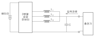
이를 위해, 종래에는 도 1에 도시된 바와 같이, 모터의 중성단에 인덕터(Lch)를 추가로 연결함으로써, 충전 시 충전 전류 및 모터 전류의 리플을 감소시켰다. 하지만, 이와 같은 방법에서는 추가 인덕터로 인한 비용 증가와 사이즈 증대의 한계점이 있었다. 또한, 다른 방식으로 종래에는 도 2에 도시된 바와 같이, 개별 인덕터 3개와 3 병렬 승압 컨버터에 인터리브드 PWM 스위칭 방식을 이용하여 충전 시 전류의 리플을 감소시켰다. 하지만, 개별 인덕터 3개를 사용하는 기존의 3병렬 승압 컨버터와는 달리 멀티 입력 급속충전 시스템에서는 각 상이 서로에게 영향을 주는 모터를 사용하기 때문에 그 경향이 달라질 수 있다는 한계가 있었다.To this end, conventionally, as shown in FIG. 1 , an inductor Lch is additionally connected to the neutral terminal of the motor to reduce charging current and motor current ripple during charging. However, this method has limitations in cost increase and size increase due to the additional inductor. In addition, in the prior art, as shown in FIG. 2, the ripple of current during charging is reduced by using an interleaved PWM switching method for three individual inductors and three parallel step-up converters. However, unlike the conventional three-parallel step-up converter that uses three individual inductors, in the multi-input fast charging system, each phase uses a motor that affects each other, so there is a limit that the tendency may vary.
상기의 배경기술로서 설명된 사항들은 본 발명의 배경에 대한 이해 증진을 위한 것일 뿐, 이 기술분야에서 통상의 지식을 가진자에게 이미 알려진 종래기술에 해당함을 인정하는 것으로 받아들여져서는 안 될 것이다.The matters described as the background art above are only for improving understanding of the background of the present invention, and should not be taken as an admission that they correspond to prior art already known to those skilled in the art.
본 발명은 상기 문제를 해결하기 위해 제안된 것으로, 차량을 급속 충전하는 과정에서 발생하는 전류리플을 저감할 수 있는 차량용 급속충전 시스템 및 방법을 제공하는데 그 목적이 있다.The present invention has been proposed to solve the above problem, and an object of the present invention is to provide a vehicle rapid charging system and method capable of reducing current ripple generated in the process of rapidly charging the vehicle.
상기 목적을 달성하기 위해 본 발명에 따른 차량용 급속충전 시스템은, 차량 배터리를 충전시키기 위한 전력을 제공하는 송전부; 3상 모터와 3상 모터와 연결된 인버터를 포함하며, 송전부로부터 제공되는 전력을 공급받아 차량 배터리를 충전하는 충전부; 기 설정된 복수의 듀티비 중 어느 하나의 듀티비를 선택하고, 상기 선택된 듀티비와 차량 배터리의 전압 값에 기반하여 충전부에 제공되는 입력전압 값을 산출하는 입력전압 산출부; 상기 산출된 입력전압 값 및 송전부에서 제공되는 전력 값에 기반하여 충전부에 입력되는 입력전류 값을 산출하는 입력전류 산출부; 상기 산출된 입력전류가 송전부로부터 충전부로 입력되도록 명령하는 송전 제어부; 및 상기 산출된 입력전압 값 및 차량 배터리의 전압 값에 기반하여 차량 배터리가 충전되도록 명령하는 충전 제어부;를 포함할 수 있다.In order to achieve the above object, a vehicle rapid charging system according to the present invention includes a power transmission unit for providing power for charging a vehicle battery; A charging unit including a three-phase motor and an inverter connected to the three-phase motor and charging the vehicle battery by receiving power supplied from the transmission unit; an input voltage calculation unit that selects one of a plurality of preset duty ratios and calculates an input voltage value provided to the charging unit based on the selected duty ratio and a voltage value of a vehicle battery; an input current calculation unit calculating an input current value input to the charging unit based on the calculated input voltage value and the power value provided from the transmission unit; a power transmission control unit commanding the calculated input current to be input from the power transmission unit to the charging unit; and a charging controller for instructing the vehicle battery to be charged based on the calculated input voltage value and the voltage value of the vehicle battery.
상기 충전부는, 상기 인버터와 병렬로 연결된 제1커패시터 및 제2커패시터; 상기 3상 모터의 중성단에 연결된 제2릴레이; 및 상기 인버터에 연결된 제1릴레이 및 제3릴레이;를 포함할 수 있다.The charging unit may include a first capacitor and a second capacitor connected in parallel with the inverter; a second relay connected to the neutral terminal of the three-phase motor; and a first relay and a third relay connected to the inverter.
상기 인버터는, 서로 연결된 복수의 구동소자를 통해 상기 3상 모터로부터 3상 신호를 입력받을 수 있다.The inverter may receive a three-phase signal from the three-phase motor through a plurality of driving elements connected to each other.
상기 송전부는, 전력을 제공하는 전원 제공부; 및 상기 전원 제공부와 병렬로 연결된 제3커패시터 및 제4커패시터;를 포함할 수 있다.The transmission unit may include a power supply unit providing power; and a third capacitor and a fourth capacitor connected in parallel with the power supply unit.
상기 충전 제어부는, 상기 산출된 입력전압 값이 상기 차량 배터리의 전압 값과 동일한 경우, 상기 제1릴레이 및 제3릴레이가 연결되도록 하여 상기 차량 배터리가 충전되도록 할 수 있다.The charging control unit may connect the first relay and the third relay to charge the vehicle battery when the calculated input voltage value is equal to the voltage value of the vehicle battery.
상기 충전 제어부는, 상기 산출된 입력전압 값이 상기 차량 배터리의 전압 값 보다 작은 경우, 상기 제2릴레이 및 제3릴레이가 연결되도록 하여, 상기 인버터를 통해 상기 입력전압을 승압시켜 차량 배터리가 충전되도록 할 수 있다.The charging control unit, when the calculated input voltage value is smaller than the voltage value of the vehicle battery, connects the second relay and the third relay to boost the input voltage through the inverter to charge the vehicle battery can do.
상기 충전 제어부는, 상기 산출된 입력전압 값이 상기 차량 배터리의 전압 값 보다 작은 경우, 상기 선택된 듀티비를 갖는 3개의 PWM 신호가 3상 모터의 각각의 상에 연결된 인버터의 복수의 구동 소자에 각각 제공되도록 할 수 있다.The charging control unit may, when the calculated input voltage value is smaller than the voltage value of the vehicle battery, send three PWM signals having the selected duty ratio to a plurality of drive elements of an inverter connected to respective phases of a three-phase motor. can be made available.
상기 3개의 PWM 신호는, 각각 120도의 위상차이를 갖는다.The three PWM signals each have a phase difference of 120 degrees.
상기 기 설정된 복수의 듀티비는 0, 1/3, 2/3 및 1을 포함할 수 있다.The plurality of preset duty ratios may include 0, 1/3, 2/3, and 1.
상기 다른 목적을 달성하기 위해 본 발명에 따른 차량용 급속충전 방법은, 차량 배터리를 충전시키기 위해 송전부로부터 제공되는 충전전력을 결정하는 단계;In order to achieve the other object, a method for fast charging a vehicle according to the present invention includes determining charging power provided from a transmission unit to charge a vehicle battery;
기 설정된 복수의 듀티비 중 어느 하나의 듀티비를 선택하고, 상기 선택된 듀티비와 차량 배터리의 전압 값에 기반하여 충전부에 제공되는 입력전압 값을 산출하는 단계; 상기 산출된 입력전압 값 및 송전부에서 제공되는 전력 값에 기반하여 충전부에 입력되는 입력전류 값을 산출하는 단계; 상기 산출된 입력전류가 송전부로부터 충전부로 입력되도록 명령하는 단계; 및 상기 산출된 입력전압 값 및 차량 배터리의 전압 값에 기반하여 차량 배터리가 충전되도록 명령하는 단계;를 포함할 수 있다. selecting one of a plurality of preset duty ratios and calculating an input voltage value provided to a charging unit based on the selected duty ratio and a voltage value of a vehicle battery; Calculating an input current value input to the charging unit based on the calculated input voltage value and the power value provided from the power transmission unit; commanding the calculated input current to be input from the power transmission unit to the charging unit; and instructing the vehicle battery to be charged based on the calculated input voltage value and the voltage value of the vehicle battery.
상기 산출된 입력전압 및 입력전류가 송전부로부터 충전부로 입력되어 차량 배터리가 충전되는 과정에서 충전전력이 변경되는 경우, 상기 입력전압 및 입력전류를 재산출하고, 재산출된 입력전압 및 입력전류가 충전부로 입력되도록 제어하는 단계;를 더 포함할 수 있다.When the calculated input voltage and input current are input from the transmission unit to the charging unit and the charging power is changed in the process of charging the vehicle battery, the input voltage and input current are recalculated, and the recalculated input voltage and input current are Controlling the input to the charging unit; may be further included.
본 발명에 따르면, 차량 배터리를 급속 충전하는 과정에서 발생하는 전류리플을 저감함으로써, 급속충전 시스템의 충전 효율을 보다 향상시킬 수 있다.According to the present invention, by reducing the current ripple generated in the process of rapidly charging the vehicle battery, it is possible to further improve the charging efficiency of the rapid charging system.
또한, 인덕터 및 커패시터 등의 소자 사용을 최소화함으로써, 원가를 절감할 수 있다.In addition, cost can be reduced by minimizing the use of devices such as inductors and capacitors.
아울러, 차량 배터리를 급속충전하는 과정에서 누설전류를 저감함으로써 급속충전 시스템의 안정성을 향상시킬 수 있다.In addition, it is possible to improve the stability of the rapid charging system by reducing the leakage current in the process of rapidly charging the vehicle battery.
도 1은 종래의 일실시예에 따른 차량용 급속충전 시스템의 구성을 도시한 도면이다.
도 2는 종래의 다른 실시예에 따른 차량용 급속충전 시스템의 구성을 도시한 도면이다.
도 3은 본 발명의 일실시예에 따른 차량용 급속충전 시스템의 구성을 도시한 도면이다.
도 4는 본 발명의 일실시예에 따른 차량용 급속충전 시스템에서, 3상 모터의 각각의 상에 연결된 인버터의 구동 소자에 각각 제공된 PWM 신호와 그에 따른 동상모드전압을 도시한 도면이다.
도 5는 본 발명의 다른 실시예에 따른 차량용 급속충전 시스템에서, 3상 모터의 각각의 상에 연결된 인버터의 구동 소자에 각각 제공된 PWM 신호와 그에 따른 동상모드전압을 도시한 도면이다.
도 6은 1/3 듀티비를 갖되 각각 120도의 위상차이를 갖는 3개의 PWM 신호가 인버터에 제공된 경우의 모터전류, 입력전류 및 누설전류의 리플을 보여주는 모의실험 결과 데이터를 나타내는 도면이다.
도 7은 2/3 듀티비를 갖되 각각 120도의 위상차이를 갖는 3개의 PWM 신호가 인버터에 제공된 경우의 모터전류, 입력전류 및 누설전류의 리플을 보여주는 모의실험 결과 데이터를 나타내는 도면이다.
도 8은 본 발명의 일실시예에 따른 차량용 급속충전 방법의 흐름을 도시한 흐름도이다.1 is a diagram showing the configuration of a rapid charging system for a vehicle according to a conventional embodiment.
2 is a diagram showing the configuration of a vehicle rapid charging system according to another conventional embodiment.
3 is a diagram showing the configuration of a rapid charging system for a vehicle according to an embodiment of the present invention.
4 is a diagram illustrating PWM signals provided to drive elements of an inverter connected to respective phases of a three-phase motor and corresponding common-mode voltages in a rapid charging system for a vehicle according to an embodiment of the present invention.
5 is a diagram illustrating PWM signals provided to drive elements of an inverter connected to respective phases of a three-phase motor and corresponding common-mode voltages in a rapid charging system for a vehicle according to another embodiment of the present invention.
6 is a diagram illustrating simulation result data showing ripples of motor current, input current, and leakage current when three PWM signals having a 1/3 duty ratio and each having a phase difference of 120 degrees are provided to the inverter.
7 is a diagram illustrating simulation result data showing ripples of motor current, input current, and leakage current when three PWM signals having a 2/3 duty ratio and each having a phase difference of 120 degrees are supplied to the inverter.
8 is a flow chart showing the flow of a rapid charging method for a vehicle according to an embodiment of the present invention.
이하에서는 첨부된 도면을 참조하여 본 발명의 바람직한 실시 예에 따른 친환경 차량용 멀티입력 급속충전 시스템 및 방법에 대해 살펴본다.Hereinafter, a multi-input fast charging system and method for an eco-friendly vehicle according to a preferred embodiment of the present invention will be described with reference to the accompanying drawings.
도 3은 본 발명의 일실시예에 따른 차량용 급속충전 시스템의 구성을 도시한 도면이고, 도 4는 본 발명의 일실시예에 따른 차량용 급속충전 시스템에서, 3상 모터의 각각의 상에 연결된 인버터의 구동 소자에 각각 제공된 PWM 신호를 도시한 도면이며, 도 5는 본 발명의 다른 실시예에 따른 차량용 급속충전 시스템에서, 3상 모터의 각각의 상에 연결된 인버터의 구동 소자에 각각 제공된 PWM 신호를 도시한 도면이다, 도 6은 1/3 듀티비를 갖되 각각 120도의 위상차이를 갖는 3개의 PWM 신호가 인버터에 제공된 경우의 모터전류, 입력전류 및 누설전류의 리플을 보여주는 모의실험 결과 데이터를 나타내는 도면이며, 도 7은 2/3 듀티비를 갖되 각각 120도의 위상차이를 갖는 3개의 PWM 신호가 인버터에 제공된 경우의 모터전류, 입력전류 및 누설전류의 리플을 보여주는 모의실험 결과 데이터를 나타내는 도면이다.Figure 3 is a diagram showing the configuration of a vehicle rapid charging system according to an embodiment of the present invention, Figure 4 is a vehicle rapid charging system according to an embodiment of the present invention, an inverter connected to each phase of a three-phase motor Figure 5 is a diagram showing the PWM signal provided to each drive element of the present invention, Figure 5 is a fast charging system for a vehicle according to another embodiment of the present invention, the PWM signal provided to each drive element of the inverter connected to each phase of the three-phase motor FIG. 6 shows simulation result data showing ripples of motor current, input current and leakage current when three PWM signals having a 1/3 duty ratio and each having a phase difference of 120 degrees are provided to the inverter. FIG. 7 is a diagram showing simulation result data showing ripples of motor current, input current, and leakage current when three PWM signals having a 2/3 duty ratio and each having a phase difference of 120 degrees are provided to the inverter. .
도 3에 도시된 바와 같이, 본 발명의 일실시예에 따른 차량용 급속충전 시스템은, 송전부(100), 충전부(200), 입력전압 산출부(300), 입력전류 산출부(400), 송전 제어부(500) 및 충전 제어부(600)를 포함하여 구성될 수 있다.As shown in FIG. 3, the vehicle rapid charging system according to an embodiment of the present invention includes a
송전부(100)는 차량 배터리를 충전시키기 위한 전력을 제공하는 역할을 한다. 구체적으로, 송전부(100)는 전력을 제공하는 전원 제공부(110) 및 전원 제공부(110)과 병렬로 연결된 제3커패시터(C3) 및 제4커패시터(C4)를 포함하여 구성될 수 있다.The
충전부(200)는 송전부(100)로부터 제공되는 전력을 공급받아 차량 배터리를 충전하는 역할을 한다. 구체적으로, 충전부(200)는 도 3에 도시된 바와 같이 3상 모터(210), 3상 모터(210)와 연결된 인버터(220), 인버터(220)와 병렬로 연결된 제1커패시터(C1), 제2커패시터(C2), 3상 모터(210)의 중성단에 연결된 제2릴레이(R2) 및 인버터(220)에 연결된 제1릴레이(R1)와 제3릴레이(R2)를 포함하여 구성될 수 있다. 여기서, 인버터(220)는 인버터((220) 내에 서로 연결된 복수의 구동소자를 통해 3상 모터(210)로부터 3상 신호를 입력받을 수 있다. 이때, 3상 신호는 3상 모터(210)의 각각의 상에 입력되는 입력전압 및 입력전류를 포함할 수 있다.The
입력전압 산출부(300)는 기 설정된 복수의 듀티비 중 어느 하나의 듀티비를 선택할 수 있다. 여기서, 기 설정된 복수의 듀티비는 0, 1/3, 2/3 및 1을 포함할 수 있다. 구체적으로, 입력전압 산출부(300)는 송전부(100)에서 제공되는 전력에 기반하여 기 설정된 복수의 듀티비 중 특정 듀티비를 선택할 수 있다. 예를 들어, 송전부(100)에서 제공되는 전력만으로 차량 배터리를 충분히 충전할 수 있는 경우에는 상기 복수의 듀티비 중 1의 듀티비를 선택할 수 있다. 다시 말해, 실시예에 따라, 차량 배터리가 800V의 배터리이고, 송전부(100)에서 800V의 배터리를 충전할 수 있는 충분한 전력을 제공할 수 있는 경우에는 입력전압 산출부(300)에서 1의 듀티비를 선택할 수 있다. 즉, 이와 같은 경우는 인버터(220)를 통해 전압의 승압이 필요없는 경우일 것이다.The
하지만, 실시예에 따라, 송전부(100)에서 제공되는 전력만으로 차량 배터리를 충분히 충전할 수 없는 경우, 즉 인버터(220)를 통해 전압의 승압이 필요한 경우에는 입력전압 산출부(300)에서 1보다 작은 듀티비 1/3 또는 2/3를 선택할 수 있다.However, according to the embodiment, when the vehicle battery cannot be sufficiently charged with only the power provided by the
한편, 입력전압 산출부(300)는 상술한 방식에 따라 선택된 듀티비와 차량 배터리의 전압 값에 기반하여 충전부에 제공되는 입력전압 값을 하기의 수학식 1을 통해 산출할 수 있다. 예를 들어, 선택된 듀티비가 1/3이고, 차량 배터리가 600V의 배터리인 경우, 하기의 수학식에 따라 충전부(200)에 입력되는 입력전압 값은 200V일 수 있다. Meanwhile, the
[수학식 1][Equation 1]
Vin = D X VbatVin = D X Vbat
Vin: 입력전압, D: 듀티비, Vbat: 차량 배터리 전압Vin: input voltage, D: duty ratio, Vbat: vehicle battery voltage
한편, 충전 제어부(600)는 듀티비 및 차량 배터리의 전압 값에 기반하여 산출된 입력전압 값이 차량 배터리의 전압 값과 동일한 경우에는, 제1릴레이(R1) 및 제3릴레이(R3)가 연결되도록 하여, 차량 배터리가 충전되도록 할 수 있다. 앞서 설명한 바와 같이 이와 같은 경우는 송전부(100)에서 제공되는 전력만으로 차량 배터리를 충분히 충전할 수 있는 경우일 것이다. 보다 구체적으로, 실시예에 따라, 차량 배터리가 800V의 배터리이고, 선택된 듀티비가 1이며, 수학식 1에 따라 산출된 입력전압 값이 800V인 경우, 충전 제어부(600)는 제1릴레이(R1) 및 제3릴레이(R3)가 연결되도록 하여 송전부(100)와 차량 배터리를 직결로 연결시켜 차량 배터리가 충전되도록 할 수 있다.Meanwhile, the
반면, 충전 제어부(600)는 듀티비 및 차량 배터리의 전압 값에 기반하여 산출된 입력전압 값이 차량 배터리의 전압 값 보다 작은 경우에는, 제2릴레이(R2) 및 제3릴레이(R3)가 연결되도록 하여, 인버터(220)를 통해 해당 입력전압을 승압시켜 차량 배터리가 충전되도록 할 수 있다. 앞서 설명한 바와 같이 이와 같은 경우는 송전부(100)에서 제공되는 전력만으로 차량 배터리를 충분히 충전할 수 없는 경우일 것이다. 보다 구체적으로, 실시예에 따라, 차량 배터리가 900V의 배터리이고, 선택된 듀티비가 1/3이며, 수학식 1에 따라 산출된 입력전압 값이 300V인 경우, 충전 제어부(600)는 제2릴레이(R2) 및 제3릴레이(R3)가 연결되도록 하여, 인버터(220)를 통해 해당 입력전압을 승압시켜 차량 배터리가 충전되도록 할 수 있다.On the other hand, the
한편, 듀티비 및 차량 배터리의 전압 값에 기반하여 산출된 입력전압 값이 차량 배터리의 전압 값 보다 작은 경우, 충전 제어부(600)는 해당 입력전압 값을 산출할 시 선택된 듀티비를 갖는 3개의 PWM 신호가 3상 모터(210)의 각각의 상에 연결된 인버터(220) 내의 복수의 구동 소자에 각각 제공되도록 할 수 있다. 이때, 인버터(220) 내의 복수의 구동 소자에 각각 제공되는 3개의 PWM 신호는 도 4 및 도 5에 도시된 바와 같이, 선택된 특정 듀티비를 갖되 각각 120도의 위상차이를 가질 수 있다.On the other hand, when the input voltage value calculated based on the duty ratio and the voltage value of the vehicle battery is smaller than the voltage value of the vehicle battery, the charging
또한, 산출된 입력전압 값이 차량 배터리의 전압 값 보다 작은 경우에, 충전 제어부(600)에서 선택되는 듀티비는 1/3 또는 2/3인 것이 바람직하다. 즉, 충전 제어부(600)는, 산출된 입력전압 값이 차량 배터리의 전압 값 보다 작은 경우, 1/3 또는 2/3의 듀티비를 갖되 각각 120도의 위상차이를 갖는 3개의 PWM 신호가 인버터(220)에 제공되도록 할 수 있다. 이때, 충전 제어부(600)에서 1/3 또는 2/3의 듀티비를 선택하는 이유에 대해서는 추후 보다 상세히 설명하기로 한다.In addition, when the calculated input voltage value is smaller than the voltage value of the vehicle battery, the duty ratio selected by the charging
한편, 입력전류 산출부(400)는 입력전압 값을 산출한 이후, 산출된 입력전압 값 및 송전부(100)에서 제공되는 전력 값에 기반하여 충전부(200)에 입력되는 입력전류 값을 산출하고, 송전 제어부(500)는 산출된 입력전류가 송전부(100)로부터 충전부(200)로 입력되도록 할 수 있다. 여기서, 입력전류 산출부(400)는 하기의 수학식 2를 통해 입력전류 값을 산출할 수 있다.Meanwhile, the input
[수학식 2][Equation 2]
Iin= P / VinIin = P / Vin
Iin: 입력전류, P: 송전부에서 제공되는 전력, Vin: 입력전압Iin: input current, P: power provided by the transmission unit, Vin: input voltage
도 3을 참조하면, 본 발명에 따른 차량용 급속충전 시스템에서 송전부(100)와 충전부(200)가 서로 연결되어 차량 배터리가 충전되는 경우, 급속충전 시스템의 효율을 저감시키는 누설전류가 발생할 수 있다. 여기서, 누설전류를 발생시키는 원인은 동상모드전압(Vsn)의 주파수 및 진폭과 관련이 있으며, 동상모드전압(Vsn)의 주파수가 0인 경우에 누설전류가 발생되지 않는다. 즉, 누설전류의 발생을 차단하기 위해서는 동상모드전압(Vsn)의 변화량을 0에 가깝게 할 필요가 있는 것이다. 여기서, 동상모드전압(Vsn)는 노드 S와 n사이의 전압으로서, 3상 모터(210)의 중성단부터 인버터(220) 직류단의 가상 중성단 사이의 전압일 수 있다.Referring to FIG. 3 , when the
보다 구체적으로, 도 4 내지 도 7을 참조하면, 1/3의 듀티비를 갖되 각각 120도의 위상차이를 갖는 3개의 PWM 신호가 인버터(220)에 제공되거나, 2/3의 듀티비를 갖되 각각 120도의 위상차이를 갖는 3개의 PWM 신호가 인버터(220)에 제공된 경우, 동상모드전압(Vsn)이 하나의 값으로 유지될 수 있다. 즉, 동상모드전압(Vsn)의 주파수가 0에 가까워지며, 그에 따라 차량 배터리의 충전 과정 중에 누설전류가 발생하는 것을 차단할 수 있고, 그 결과 급속충전 시스템의 효율을 보다 향상시킬 수 있다.More specifically, referring to FIGS. 4 to 7, three PWM signals having a duty ratio of 1/3 but each having a phase difference of 120 degrees are provided to the
아울러, 도 6 및 7을 참조하면, 1/3 또는 2/3의 듀티비를 갖되 각각 120도의 위상차이를 갖는 3개의 PWM 신호가 인버터에 제공함으로써, 입력전류(Vin), 모터전류, 누설전류가 모두 저감시킬 수 있고, 그에 따라 급속충전 시스템의 효율을 향상시킬 수 있다.In addition, referring to FIGS. 6 and 7, three PWM signals having a duty ratio of 1/3 or 2/3 but each having a phase difference of 120 degrees are provided to the inverter, thereby increasing input current (Vin), motor current, and leakage current. can all be reduced, thereby improving the efficiency of the rapid charging system.
다시 말해, 본 발명에 따르면, 송전부(100)에서 제공되는 전력만으로 차량 배터리를 충분히 충전할 수 없는 경우, 충전 제어부(600)에서 제2릴레이(R2) 및 제3릴레이(R3)가 연결되도록 하여 인버터를 통해 승압과정을 거쳐 차량 배터리가 충전되도록 하는데, 이때 충전 제어부(600)에서는 송전부(100)에서 제공되는 전력 값에 따라 1/3 또는 2/3의 듀티비를 갖되 각각 120도의 위상차이를 갖는 3개의 PWM 신호가 인버터(220)에 제공되도록 함으로써, 입력전압을 승압시켜 차량 배터리를 충전시키되, 충전 과정 중에 입력전류(Vin), 모터전류, 누설전류를 모두 저감시킬 수 있고, 그에 따라 급속충전 시스템의 효율 및 안정성을 보다 향상시킬 수 있다.In other words, according to the present invention, when the vehicle battery cannot be sufficiently charged with only the power provided by the
도 8은 본 발명의 일실시예에 따른 차량용 급속충전 방법의 흐름을 도시한 흐름도이다. 도 8에 도시된 바와같이, 차량용 급속충전 방법은, 차량 배터리를 충전시키기 위해 송전부로부터 제공되는 충전전력을 결정하는 단계; 기 설정된 복수의 듀티비 중 어느 하나의 듀티비를 선택하고, 상기 선택된 듀티비와 차량 배터리의 전압 값에 기반하여 충전부에 제공되는 입력전압 값을 산출하는 단계; 상기 산출된 입력전압 값 및 송전부에서 제공되는 전력 값에 기반하여 충전부에 입력되는 입력전류 값을 산출하는 단계; 상기 산출된 입력전류가 송전부로부터 충전부로 입력되도록 명령하는 단계; 및 상기 산출된 입력전압 값 및 차량 배터리의 전압 값에 기반하여 차량 배터리가 충전되도록 명령하는 단계;를 포함할 수 있다. 8 is a flow chart showing the flow of a rapid charging method for a vehicle according to an embodiment of the present invention. As shown in FIG. 8 , a fast charging method for a vehicle includes determining charging power provided from a transmission unit to charge a vehicle battery; selecting one of a plurality of preset duty ratios and calculating an input voltage value provided to a charging unit based on the selected duty ratio and a voltage value of a vehicle battery; Calculating an input current value input to the charging unit based on the calculated input voltage value and the power value provided from the power transmission unit; commanding the calculated input current to be input from the power transmission unit to the charging unit; and instructing the vehicle battery to be charged based on the calculated input voltage value and the voltage value of the vehicle battery.
또한, 산출된 입력전압 및 입력전류가 송전부로부터 충전부로 입력되어 차량 배터리가 충전되는 과정에서 충전전력이 변경되는 경우, 입력전압 및 입력전류를 재산출하고, 재산출된 입력전압 및 입력전류가 충전부로 입력되도록 제어하는 단계;를 더 포함할 수 있다.In addition, when the calculated input voltage and input current are input from the transmission unit to the charging unit and the charging power is changed in the process of charging the vehicle battery, the input voltage and input current are recalculated, and the recalculated input voltage and input current are Controlling the input to the charging unit; may be further included.
한편, 차량용 급속충전 방법의 각 단계에서의 세부적인 기술적인 특징은 차량용 급속충전 시스템에서의 기술특징과 동일하므로 그에 대한 상세한 설명은 생략하기로 한다.On the other hand, since the detailed technical characteristics of each step of the vehicle rapid charging method are the same as those of the vehicle rapid charging system, a detailed description thereof will be omitted.
100: 송전부 110: 전원 공급부
200: 충전부 210: 3상 모터
220: 인버터 300: 입력전압 산출부
400: 입력전류 산출부 500: 송전 제어부
600: 충전 제어부
C1: 제1커패시터 C2: 제2커패시터
C3: 제3커패시터 C4: 제4커패시터
R1: 제1릴레이 R2: 제2릴레이
R3: 제3릴레이 C: 차량 샤시
G: 그라운드 Vsn: 동상모드전압
Van: 3상 모터의 a상의 극전압
Vbn: 3상 모터의 b상의 극전압
Vcn: 3상 모터의 c상의 극전압100: power transmission unit 110: power supply unit
200: charging unit 210: 3-phase motor
220: inverter 300: input voltage calculation unit
400: input current calculation unit 500: transmission control unit
600: charging control unit
C1: first capacitor C2: second capacitor
C3: 3rd capacitor C4: 4th capacitor
R1: 1st relay R2: 2nd relay
R3: 3rd relay C: vehicle chassis
G: ground Vsn: common mode voltage
Van: pole voltage of phase a of a three-phase motor
Vbn: pole voltage of phase b of a three-phase motor
Vcn: pole voltage of phase c of a three-phase motor
Claims (11)
3상 모터와 3상 모터와 연결된 인버터를 포함하며, 송전부로부터 제공되는 전력을 공급받아 차량 배터리를 충전하는 충전부;
상기 송전부로부터 제공되는 전력을 기반으로 기 설정된 복수의 듀티비 중 어느 하나의 듀티비를 선택하고, 상기 선택된 듀티비와 차량 배터리의 전압 값에 기반하여 충전부에 제공되는 입력전압 값을 산출하는 입력전압 산출부;
상기 산출된 입력전압 값 및 송전부에서 제공되는 전력 값에 기반하여 충전부에 입력되는 입력전류 값을 산출하는 입력전류 산출부;
상기 산출된 입력전류가 송전부로부터 충전부로 입력되도록 명령하는 송전 제어부; 및
상기 산출된 입력전압 값 및 차량 배터리의 전압 값에 기반하여 차량 배터리가 충전되도록 명령하는 충전 제어부;를 포함하는 차량용 급속충전 시스템.a power transmission unit providing power to charge a vehicle battery;
A charging unit including a three-phase motor and an inverter connected to the three-phase motor and charging the vehicle battery by receiving power supplied from the transmission unit;
An input for selecting one of a plurality of preset duty ratios based on the power provided from the transmission unit and calculating an input voltage value provided to the charging unit based on the selected duty ratio and the voltage value of the vehicle battery. voltage calculator;
an input current calculation unit calculating an input current value input to the charging unit based on the calculated input voltage value and the power value provided from the transmission unit;
a power transmission control unit commanding the calculated input current to be input from the power transmission unit to the charging unit; and
A charging control unit for instructing the vehicle battery to be charged based on the calculated input voltage value and the voltage value of the vehicle battery; fast charging system for a vehicle comprising a.
상기 인버터와 병렬로 연결된 제1커패시터 및 제2커패시터;
상기 3상 모터의 중성단에 연결된 제2릴레이; 및
상기 인버터에 연결된 제1릴레이 및 제3릴레이;를 포함하는 것을 특징으로 하는 차량용 급속충전 시스템.The method according to claim 1, wherein the charging unit,
a first capacitor and a second capacitor connected in parallel with the inverter;
a second relay connected to the neutral terminal of the three-phase motor; and
A first relay and a third relay connected to the inverter; fast charging system for a vehicle comprising a.
서로 연결된 복수의 구동소자를 통해 상기 3상 모터로부터 3상 신호를 입력받는 것을 특징으로 하는 차량용 급속충전 시스템.The method according to claim 1, wherein the inverter,
Vehicle rapid charging system, characterized in that for receiving a three-phase signal from the three-phase motor through a plurality of driving elements connected to each other.
전력을 제공하는 전원 제공부; 및
상기 전원 제공부와 병렬로 연결된 제3커패시터 및 제4커패시터;를 포함하는 것을 특징으로 하는 차량용 급속충전 시스템.The method according to claim 1, wherein the power transmission unit,
a power supply unit that provides power; and
A vehicle rapid charging system comprising a; third capacitor and fourth capacitor connected in parallel with the power supply unit.
상기 산출된 입력전압 값이 상기 차량 배터리의 전압 값과 동일한 경우, 상기 제1릴레이 및 제3릴레이가 연결되도록 하여 상기 차량 배터리가 충전되도록 하는 것을 특징으로 하는 차량용 급속충전 시스템.The method according to claim 2, wherein the charging control unit,
When the calculated input voltage value is the same as the voltage value of the vehicle battery, the first relay and the third relay are connected so that the vehicle battery is charged.
상기 산출된 입력전압 값이 상기 차량 배터리의 전압 값 보다 작은 경우, 상기 제2릴레이 및 제3릴레이가 연결되도록 하여, 상기 인버터를 통해 상기 입력전압을 승압시켜 차량 배터리가 충전되도록 하는 것을 특징으로 하는 차량용 급속충전 시스템.The method according to claim 2, wherein the charging control unit,
When the calculated input voltage value is smaller than the voltage value of the vehicle battery, the second relay and the third relay are connected so that the input voltage is boosted through the inverter to charge the vehicle battery. Characterized in that Vehicle fast charging system.
상기 산출된 입력전압 값이 상기 차량 배터리의 전압 값 보다 작은 경우, 상기 선택된 듀티비를 갖는 3개의 PWM 신호가 3상 모터의 각각의 상에 연결된 인버터의 복수의 구동 소자에 각각 제공되도록 하는 것을 특징으로 하는 차량용 급속충전 시스템.The method of claim 1, wherein the charging control unit,
When the calculated input voltage value is smaller than the voltage value of the vehicle battery, three PWM signals having the selected duty ratio are provided to a plurality of driving elements of an inverter connected to respective phases of the three-phase motor, respectively. A fast charging system for vehicles.
각각 120도의 위상차이를 갖는 것을 특징으로 하는 차량용 급속충전 시스템.The method according to claim 7, wherein the three PWM signals,
Vehicle fast charging system, characterized in that each has a phase difference of 120 degrees.
0, 1/3, 2/3 및 1을 포함하는 것을 특징으로 하는 차량용 급속충전 시스템.The method according to claim 1, wherein the plurality of preset duty ratios,
A vehicle rapid charging system comprising 0, 1/3, 2/3 and 1.
차량 배터리를 충전시키기 위해 송전부로부터 제공되는 충전전력을 결정하는 단계;
상기 송전부로부터 제공되는 충전전력을 기반으로 기 설정된 복수의 듀티비 중 어느 하나의 듀티비를 선택하고, 상기 선택된 듀티비와 차량 배터리의 전압 값에 기반하여 충전부에 제공되는 입력전압 값을 산출하는 단계;
상기 산출된 입력전압 값 및 송전부에서 제공되는 전력 값에 기반하여 충전부에 입력되는 입력전류 값을 산출하는 단계;
상기 산출된 입력전류가 송전부로부터 충전부로 입력되도록 명령하는 단계; 및
상기 산출된 입력전압 값 및 차량 배터리의 전압 값에 기반하여 차량 배터리가 충전되도록 명령하는 단계;를 포함하는 차량용 급속충전 방법.The vehicle rapid charging method using the vehicle rapid charging system of claim 1,
determining charging power provided from a transmission unit to charge a vehicle battery;
Selecting one of a plurality of preset duty ratios based on the charging power provided from the power transmission unit, and calculating an input voltage value provided to the charging unit based on the selected duty ratio and the voltage value of the vehicle battery step;
Calculating an input current value input to the charging unit based on the calculated input voltage value and the power value provided from the power transmission unit;
commanding the calculated input current to be input from the power transmission unit to the charging unit; and
A fast charging method for a vehicle comprising: commanding the vehicle battery to be charged based on the calculated input voltage value and the voltage value of the vehicle battery.
상기 산출된 입력전압 및 입력전류가 송전부로부터 충전부로 입력되어 차량 배터리가 충전되는 과정에서 충전전력이 변경되는 경우,
상기 입력전압 및 입력전류를 재산출하고, 재산출된 입력전압 및 입력전류가 충전부로 입력되도록 제어하는 단계;를 더 포함하는 차량용 급속충전 방법.The method of claim 10,
When the calculated input voltage and input current are input from the transmission unit to the charging unit and the charging power is changed in the process of charging the vehicle battery,
Re-calculating the input voltage and input current, and controlling the re-calculated input voltage and input current to be input to the charging unit; fast charging method for a vehicle further comprising.
Priority Applications (4)
| Application Number | Priority Date | Filing Date | Title |
|---|---|---|---|
| KR1020180043152A KR102542948B1 (en) | 2018-04-13 | 2018-04-13 | Fast charging system and method for vehicle |
| US16/168,295 US10857898B2 (en) | 2018-04-13 | 2018-10-23 | Charging system and method for vehicle |
| DE102018219336.3A DE102018219336B4 (en) | 2018-04-13 | 2018-11-13 | Charging system and procedure for vehicles |
| CN201811354544.2A CN110386006B (en) | 2018-04-13 | 2018-11-14 | Charging system and method for vehicle |
Applications Claiming Priority (1)
| Application Number | Priority Date | Filing Date | Title |
|---|---|---|---|
| KR1020180043152A KR102542948B1 (en) | 2018-04-13 | 2018-04-13 | Fast charging system and method for vehicle |
Publications (2)
| Publication Number | Publication Date |
|---|---|
| KR20190119778A KR20190119778A (en) | 2019-10-23 |
| KR102542948B1 true KR102542948B1 (en) | 2023-06-14 |
Family
ID=68053149
Family Applications (1)
| Application Number | Title | Priority Date | Filing Date |
|---|---|---|---|
| KR1020180043152A Active KR102542948B1 (en) | 2018-04-13 | 2018-04-13 | Fast charging system and method for vehicle |
Country Status (4)
| Country | Link |
|---|---|
| US (1) | US10857898B2 (en) |
| KR (1) | KR102542948B1 (en) |
| CN (1) | CN110386006B (en) |
| DE (1) | DE102018219336B4 (en) |
Cited By (2)
| Publication number | Priority date | Publication date | Assignee | Title |
|---|---|---|---|---|
| US12381410B2 (en) * | 2023-02-27 | 2025-08-05 | Toyota Jidosha Kabushiki Kaisha | Charging device |
| KR102952392B1 (en) | 2020-04-28 | 2026-04-14 | 현대자동차주식회사 | System and method for charging using motor driving system |
Families Citing this family (29)
| Publication number | Priority date | Publication date | Assignee | Title |
|---|---|---|---|---|
| KR102565333B1 (en) * | 2018-12-12 | 2023-08-16 | 현대자동차주식회사 | Apparatus of controlling charging system using motor driving system |
| KR102687178B1 (en) * | 2019-04-01 | 2024-07-22 | 현대자동차주식회사 | Multi-input charging system and method using motor driving system |
| KR102663664B1 (en) | 2019-05-17 | 2024-05-03 | 현대자동차주식회사 | Multi-input charging system and method using motor driving system |
| KR102814383B1 (en) | 2019-05-20 | 2025-05-29 | 현대자동차주식회사 | System for supplying charging power using motor driving system |
| KR102796848B1 (en) | 2019-08-06 | 2025-04-17 | 현대자동차주식회사 | System and method for charging using motor driving system |
| KR102789573B1 (en) | 2019-08-30 | 2025-04-01 | 현대자동차주식회사 | System and method for charging using motor driving system |
| KR102812097B1 (en) | 2019-12-13 | 2025-05-23 | 현대자동차주식회사 | Power converting apparatus for multi voltage charging |
| KR102829604B1 (en) * | 2019-12-16 | 2025-07-03 | 현대자동차 주식회사 | Cooling system for vehicle wireless charging and control methof for the same |
| KR102797069B1 (en) * | 2020-06-05 | 2025-04-18 | 현대자동차주식회사 | Vehicle and method for controlling thereof |
| KR102907619B1 (en) | 2020-11-09 | 2026-01-02 | 현대자동차주식회사 | Multi input charging system and method using motor driving device |
| CN112937337B (en) | 2021-01-21 | 2025-05-13 | 华为数字能源技术有限公司 | Charging system and electric vehicle |
| KR102511627B1 (en) | 2021-02-01 | 2023-03-21 | 스마트론파워(주) | Rapid charging apparatus and method for preventing battery-damage |
| KR20220111119A (en) | 2021-02-01 | 2022-08-09 | 스마트론파워(주) | Rapid charging apparatus and method for preventing battery-damage |
| US12420655B2 (en) * | 2021-03-01 | 2025-09-23 | Volvo Car Corporation | Charging system of an electric vehicle using traction inverter and electric machine |
| US12401215B2 (en) * | 2021-03-01 | 2025-08-26 | Volvo Car Corporation | Voltage conversion system for battery electric powertrain with common minus-pole |
| CN115230494A (en) * | 2021-04-25 | 2022-10-25 | 德尔福科技(苏州)有限公司 | Vehicle high voltage charging system with motor drive system |
| KR20230003888A (en) | 2021-06-30 | 2023-01-06 | 현대자동차주식회사 | Charging system and method using motor driving system |
| KR20230119438A (en) | 2022-02-07 | 2023-08-16 | 현대자동차주식회사 | Multi input charging system and method using motor driving device |
| DE102022000711B4 (en) * | 2022-02-28 | 2023-08-03 | Mercedes-Benz Group AG | Method of operating an electric drive system for a vehicle |
| KR102868657B1 (en) | 2022-06-13 | 2025-10-14 | 주식회사 이피티 | Charging system using motor coil |
| CN115320424B (en) * | 2022-07-14 | 2025-03-28 | 华为数字能源技术有限公司 | A powertrain, charging control method and electric vehicle |
| JP7564168B2 (en) * | 2022-09-30 | 2024-10-08 | 本田技研工業株式会社 | Energy Storage System |
| CN115622479B (en) * | 2022-11-14 | 2024-01-02 | 珠海市伟高变频科技有限公司 | Control method for exciting motor core of compressor to generate vortex heating |
| JP7524282B2 (en) * | 2022-11-30 | 2024-07-29 | 本田技研工業株式会社 | Energy Storage System |
| JP7577722B2 (en) * | 2022-11-30 | 2024-11-05 | 本田技研工業株式会社 | Energy Storage System |
| JP7577723B2 (en) * | 2022-11-30 | 2024-11-05 | 本田技研工業株式会社 | Energy Storage System |
| KR20240085706A (en) | 2022-12-08 | 2024-06-17 | 현대자동차주식회사 | Electrified vehicle and method controlling for the same |
| KR102745380B1 (en) | 2023-03-06 | 2024-12-23 | 이래에이엠에스 주식회사 | Charging system for electric vehicles |
| KR20240177863A (en) | 2023-06-20 | 2024-12-30 | 현대자동차주식회사 | Electrified vehicle and method controlling for the same |
Citations (1)
| Publication number | Priority date | Publication date | Assignee | Title |
|---|---|---|---|---|
| US20140368170A1 (en) * | 2011-12-31 | 2014-12-18 | Byd Company Limited | Electric automobile and charging system for the electric automobile |
Family Cites Families (10)
| Publication number | Priority date | Publication date | Assignee | Title |
|---|---|---|---|---|
| JP5493568B2 (en) * | 2009-08-06 | 2014-05-14 | 株式会社デンソー | Electric motor drive device, electric motor drive device control method, and electric device |
| KR101213921B1 (en) | 2010-11-03 | 2012-12-18 | 넥스콘 테크놀러지 주식회사 | rapid charge of battery pack for electric vehicle |
| WO2012131969A1 (en) * | 2011-03-31 | 2012-10-04 | トヨタ自動車株式会社 | Power supply system for vehicle |
| FR2973963B1 (en) * | 2011-04-08 | 2013-04-12 | Valeo Sys Controle Moteur Sas | CHARGE TRANSFER DEVICE AND METHOD FOR MANAGING THE SAME |
| KR101568225B1 (en) * | 2013-02-06 | 2016-07-20 | 엘지전자 주식회사 | charging apparatus and electric vehicle including the same |
| US9783070B2 (en) * | 2014-02-14 | 2017-10-10 | Jabil Circuit, Inc. | Charge transfer system |
| KR101592743B1 (en) * | 2014-07-28 | 2016-02-12 | 현대자동차주식회사 | Method for controlling on-board charger of eco-friendly vehicle |
| KR101684064B1 (en) * | 2015-02-12 | 2016-12-07 | 현대자동차주식회사 | Charging system of electric vehicle |
| DE102016110870A1 (en) * | 2016-06-14 | 2017-12-14 | Dr. Ing. H.C. F. Porsche Aktiengesellschaft | Charging system for charging a high-voltage battery of an electrically driven vehicle |
| US10425032B2 (en) * | 2017-03-03 | 2019-09-24 | General Electric Company | Drive system and method of operation thereof for reducing DC link current ripple |
-
2018
- 2018-04-13 KR KR1020180043152A patent/KR102542948B1/en active Active
- 2018-10-23 US US16/168,295 patent/US10857898B2/en active Active
- 2018-11-13 DE DE102018219336.3A patent/DE102018219336B4/en active Active
- 2018-11-14 CN CN201811354544.2A patent/CN110386006B/en active Active
Patent Citations (1)
| Publication number | Priority date | Publication date | Assignee | Title |
|---|---|---|---|---|
| US20140368170A1 (en) * | 2011-12-31 | 2014-12-18 | Byd Company Limited | Electric automobile and charging system for the electric automobile |
Cited By (2)
| Publication number | Priority date | Publication date | Assignee | Title |
|---|---|---|---|---|
| KR102952392B1 (en) | 2020-04-28 | 2026-04-14 | 현대자동차주식회사 | System and method for charging using motor driving system |
| US12381410B2 (en) * | 2023-02-27 | 2025-08-05 | Toyota Jidosha Kabushiki Kaisha | Charging device |
Also Published As
| Publication number | Publication date |
|---|---|
| DE102018219336A1 (en) | 2019-10-17 |
| US20190315234A1 (en) | 2019-10-17 |
| CN110386006A (en) | 2019-10-29 |
| CN110386006B (en) | 2023-10-20 |
| US10857898B2 (en) | 2020-12-08 |
| KR20190119778A (en) | 2019-10-23 |
| DE102018219336B4 (en) | 2025-04-30 |
Similar Documents
| Publication | Publication Date | Title |
|---|---|---|
| KR102542948B1 (en) | Fast charging system and method for vehicle | |
| US11772505B2 (en) | System and method for charging using motor driving system | |
| US11171504B2 (en) | Charging system using motor driving system | |
| KR102952392B1 (en) | System and method for charging using motor driving system | |
| US10358041B2 (en) | Electric vehicle | |
| KR102523253B1 (en) | Battery charger for electric vehicle | |
| KR102528230B1 (en) | Battery charger for electric vehicle | |
| CN112622658B (en) | Battery chargers for electric vehicles | |
| KR102524192B1 (en) | Battery charger for electric vehicle | |
| CN112910037A (en) | Motor controller, motor control system, power assembly and electric vehicle | |
| CN112937337A (en) | Charging system and electric automobile | |
| Dusmez et al. | A novel low cost integrated on-board charger topology for electric vehicles and plug-in hybrid electric vehicles | |
| US11135927B2 (en) | Four wheel drive vehicle | |
| KR20190118084A (en) | Power converting system for vehicle | |
| EP3857693A1 (en) | System and method for a magnetically coupled inductor boost and multiphase buck converter with split duty cycle | |
| US10790763B2 (en) | HEV e-drives with HV boost ratio and wide DC bus voltage range | |
| Ahmed et al. | Performance analysis of bi-directional DC-DC converters for electric vehicles and charging infrastructure | |
| KR20190115831A (en) | Battery charger for electric vehicle | |
| JP6798286B2 (en) | Electric vehicle charging system and in-vehicle charging unit | |
| US20190181766A1 (en) | Interleaved dc-dc converter for electrified vehicles | |
| JP7440586B2 (en) | power regulation circuit | |
| CN115179789A (en) | Power conversion device, charging pile, vehicle-mounted charger and electric automobile | |
| Kim et al. | Mode change method of bi-directional DC/DC converter for electric vehicle | |
| US20260116194A1 (en) | Electric power supply system for a vehicle | |
| US20260054585A1 (en) | Electrified vehicle |
Legal Events
| Date | Code | Title | Description |
|---|---|---|---|
| PA0109 | Patent application |
St.27 status event code: A-0-1-A10-A12-nap-PA0109 |
|
| PN2301 | Change of applicant |
St.27 status event code: A-3-3-R10-R13-asn-PN2301 St.27 status event code: A-3-3-R10-R11-asn-PN2301 |
|
| P22-X000 | Classification modified |
St.27 status event code: A-2-2-P10-P22-nap-X000 |
|
| P22-X000 | Classification modified |
St.27 status event code: A-2-2-P10-P22-nap-X000 |
|
| R18-X000 | Changes to party contact information recorded |
St.27 status event code: A-3-3-R10-R18-oth-X000 |
|
| R18-X000 | Changes to party contact information recorded |
St.27 status event code: A-3-3-R10-R18-oth-X000 |
|
| PG1501 | Laying open of application |
St.27 status event code: A-1-1-Q10-Q12-nap-PG1501 |
|
| P22-X000 | Classification modified |
St.27 status event code: A-2-2-P10-P22-nap-X000 |
|
| A201 | Request for examination | ||
| PA0201 | Request for examination |
St.27 status event code: A-1-2-D10-D11-exm-PA0201 |
|
| PN2301 | Change of applicant |
St.27 status event code: A-3-3-R10-R13-asn-PN2301 St.27 status event code: A-3-3-R10-R11-asn-PN2301 |
|
| P22-X000 | Classification modified |
St.27 status event code: A-2-2-P10-P22-nap-X000 |
|
| E902 | Notification of reason for refusal | ||
| PE0902 | Notice of grounds for rejection |
St.27 status event code: A-1-2-D10-D21-exm-PE0902 |
|
| P11-X000 | Amendment of application requested |
St.27 status event code: A-2-2-P10-P11-nap-X000 |
|
| P13-X000 | Application amended |
St.27 status event code: A-2-2-P10-P13-nap-X000 |
|
| E701 | Decision to grant or registration of patent right | ||
| PE0701 | Decision of registration |
St.27 status event code: A-1-2-D10-D22-exm-PE0701 |
|
| PR0701 | Registration of establishment |
St.27 status event code: A-2-4-F10-F11-exm-PR0701 |
|
| PR1002 | Payment of registration fee |
St.27 status event code: A-2-2-U10-U11-oth-PR1002 Fee payment year number: 1 |
|
| PG1601 | Publication of registration |
St.27 status event code: A-4-4-Q10-Q13-nap-PG1601 |