KR102538298B1 - Dust collecting apparatus for capturing dust generated in break apparatus of transportation means and manufacturing method of dust collecting apparatus - Google Patents
Dust collecting apparatus for capturing dust generated in break apparatus of transportation means and manufacturing method of dust collecting apparatus Download PDFInfo
- Publication number
- KR102538298B1 KR102538298B1 KR1020200185420A KR20200185420A KR102538298B1 KR 102538298 B1 KR102538298 B1 KR 102538298B1 KR 1020200185420 A KR1020200185420 A KR 1020200185420A KR 20200185420 A KR20200185420 A KR 20200185420A KR 102538298 B1 KR102538298 B1 KR 102538298B1
- Authority
- KR
- South Korea
- Prior art keywords
- collector
- porous ceramic
- foam
- rotor
- pores
- Prior art date
- Legal status (The legal status is an assumption and is not a legal conclusion. Google has not performed a legal analysis and makes no representation as to the accuracy of the status listed.)
- Active
Links
Images






Classifications
-
- C—CHEMISTRY; METALLURGY
- C04—CEMENTS; CONCRETE; ARTIFICIAL STONE; CERAMICS; REFRACTORIES
- C04B—LIME, MAGNESIA; SLAG; CEMENTS; COMPOSITIONS THEREOF, e.g. MORTARS, CONCRETE OR LIKE BUILDING MATERIALS; ARTIFICIAL STONE; CERAMICS; REFRACTORIES; TREATMENT OF NATURAL STONE
- C04B38/00—Porous mortars, concrete, artificial stone or ceramic ware; Preparation thereof
- C04B38/06—Porous mortars, concrete, artificial stone or ceramic ware; Preparation thereof by burning-out added substances by burning natural expanding materials or by sublimating or melting out added substances
- C04B38/0615—Porous mortars, concrete, artificial stone or ceramic ware; Preparation thereof by burning-out added substances by burning natural expanding materials or by sublimating or melting out added substances the burned-out substance being a monolitic element having approximately the same dimensions as the final article, e.g. a porous polyurethane sheet or a prepreg obtained by bonding together resin particles
-
- F—MECHANICAL ENGINEERING; LIGHTING; HEATING; WEAPONS; BLASTING
- F16—ENGINEERING ELEMENTS AND UNITS; GENERAL MEASURES FOR PRODUCING AND MAINTAINING EFFECTIVE FUNCTIONING OF MACHINES OR INSTALLATIONS; THERMAL INSULATION IN GENERAL
- F16D—COUPLINGS FOR TRANSMITTING ROTATION; CLUTCHES; BRAKES
- F16D65/00—Parts or details
- F16D65/0031—Devices for retaining friction material debris, e.g. dust collectors or filters
-
- B—PERFORMING OPERATIONS; TRANSPORTING
- B01—PHYSICAL OR CHEMICAL PROCESSES OR APPARATUS IN GENERAL
- B01D—SEPARATION
- B01D39/00—Filtering material for liquid or gaseous fluids
- B01D39/14—Other self-supporting filtering material ; Other filtering material
- B01D39/20—Other self-supporting filtering material ; Other filtering material of inorganic material, e.g. asbestos paper, metallic filtering material of non-woven wires
- B01D39/2068—Other inorganic materials, e.g. ceramics
- B01D39/2093—Ceramic foam
-
- B—PERFORMING OPERATIONS; TRANSPORTING
- B01—PHYSICAL OR CHEMICAL PROCESSES OR APPARATUS IN GENERAL
- B01D—SEPARATION
- B01D46/00—Filters or filtering processes specially modified for separating dispersed particles from gases or vapours
- B01D46/0002—Casings; Housings; Frame constructions
-
- B—PERFORMING OPERATIONS; TRANSPORTING
- B01—PHYSICAL OR CHEMICAL PROCESSES OR APPARATUS IN GENERAL
- B01D—SEPARATION
- B01D46/00—Filters or filtering processes specially modified for separating dispersed particles from gases or vapours
- B01D46/10—Particle separators, e.g. dust precipitators, using filter plates, sheets or pads having plane surfaces
- B01D46/103—Curved filtering elements
-
- C—CHEMISTRY; METALLURGY
- C04—CEMENTS; CONCRETE; ARTIFICIAL STONE; CERAMICS; REFRACTORIES
- C04B—LIME, MAGNESIA; SLAG; CEMENTS; COMPOSITIONS THEREOF, e.g. MORTARS, CONCRETE OR LIKE BUILDING MATERIALS; ARTIFICIAL STONE; CERAMICS; REFRACTORIES; TREATMENT OF NATURAL STONE
- C04B35/00—Shaped ceramic products characterised by their composition; Ceramics compositions; Processing powders of inorganic compounds preparatory to the manufacturing of ceramic products
- C04B35/01—Shaped ceramic products characterised by their composition; Ceramics compositions; Processing powders of inorganic compounds preparatory to the manufacturing of ceramic products based on oxide ceramics
- C04B35/10—Shaped ceramic products characterised by their composition; Ceramics compositions; Processing powders of inorganic compounds preparatory to the manufacturing of ceramic products based on oxide ceramics based on aluminium oxide
-
- C—CHEMISTRY; METALLURGY
- C04—CEMENTS; CONCRETE; ARTIFICIAL STONE; CERAMICS; REFRACTORIES
- C04B—LIME, MAGNESIA; SLAG; CEMENTS; COMPOSITIONS THEREOF, e.g. MORTARS, CONCRETE OR LIKE BUILDING MATERIALS; ARTIFICIAL STONE; CERAMICS; REFRACTORIES; TREATMENT OF NATURAL STONE
- C04B35/00—Shaped ceramic products characterised by their composition; Ceramics compositions; Processing powders of inorganic compounds preparatory to the manufacturing of ceramic products
- C04B35/01—Shaped ceramic products characterised by their composition; Ceramics compositions; Processing powders of inorganic compounds preparatory to the manufacturing of ceramic products based on oxide ceramics
- C04B35/10—Shaped ceramic products characterised by their composition; Ceramics compositions; Processing powders of inorganic compounds preparatory to the manufacturing of ceramic products based on oxide ceramics based on aluminium oxide
- C04B35/111—Fine ceramics
-
- C—CHEMISTRY; METALLURGY
- C04—CEMENTS; CONCRETE; ARTIFICIAL STONE; CERAMICS; REFRACTORIES
- C04B—LIME, MAGNESIA; SLAG; CEMENTS; COMPOSITIONS THEREOF, e.g. MORTARS, CONCRETE OR LIKE BUILDING MATERIALS; ARTIFICIAL STONE; CERAMICS; REFRACTORIES; TREATMENT OF NATURAL STONE
- C04B35/00—Shaped ceramic products characterised by their composition; Ceramics compositions; Processing powders of inorganic compounds preparatory to the manufacturing of ceramic products
- C04B35/515—Shaped ceramic products characterised by their composition; Ceramics compositions; Processing powders of inorganic compounds preparatory to the manufacturing of ceramic products based on non-oxide ceramics
- C04B35/553—Shaped ceramic products characterised by their composition; Ceramics compositions; Processing powders of inorganic compounds preparatory to the manufacturing of ceramic products based on non-oxide ceramics based on fluorides
-
- C—CHEMISTRY; METALLURGY
- C04—CEMENTS; CONCRETE; ARTIFICIAL STONE; CERAMICS; REFRACTORIES
- C04B—LIME, MAGNESIA; SLAG; CEMENTS; COMPOSITIONS THEREOF, e.g. MORTARS, CONCRETE OR LIKE BUILDING MATERIALS; ARTIFICIAL STONE; CERAMICS; REFRACTORIES; TREATMENT OF NATURAL STONE
- C04B35/00—Shaped ceramic products characterised by their composition; Ceramics compositions; Processing powders of inorganic compounds preparatory to the manufacturing of ceramic products
- C04B35/515—Shaped ceramic products characterised by their composition; Ceramics compositions; Processing powders of inorganic compounds preparatory to the manufacturing of ceramic products based on non-oxide ceramics
- C04B35/56—Shaped ceramic products characterised by their composition; Ceramics compositions; Processing powders of inorganic compounds preparatory to the manufacturing of ceramic products based on non-oxide ceramics based on carbides or oxycarbides
- C04B35/565—Shaped ceramic products characterised by their composition; Ceramics compositions; Processing powders of inorganic compounds preparatory to the manufacturing of ceramic products based on non-oxide ceramics based on carbides or oxycarbides based on silicon carbide
-
- C—CHEMISTRY; METALLURGY
- C04—CEMENTS; CONCRETE; ARTIFICIAL STONE; CERAMICS; REFRACTORIES
- C04B—LIME, MAGNESIA; SLAG; CEMENTS; COMPOSITIONS THEREOF, e.g. MORTARS, CONCRETE OR LIKE BUILDING MATERIALS; ARTIFICIAL STONE; CERAMICS; REFRACTORIES; TREATMENT OF NATURAL STONE
- C04B35/00—Shaped ceramic products characterised by their composition; Ceramics compositions; Processing powders of inorganic compounds preparatory to the manufacturing of ceramic products
- C04B35/622—Forming processes; Processing powders of inorganic compounds preparatory to the manufacturing of ceramic products
- C04B35/62227—Forming processes; Processing powders of inorganic compounds preparatory to the manufacturing of ceramic products obtaining fibres
- C04B35/62231—Forming processes; Processing powders of inorganic compounds preparatory to the manufacturing of ceramic products obtaining fibres based on oxide ceramics
-
- C—CHEMISTRY; METALLURGY
- C04—CEMENTS; CONCRETE; ARTIFICIAL STONE; CERAMICS; REFRACTORIES
- C04B—LIME, MAGNESIA; SLAG; CEMENTS; COMPOSITIONS THEREOF, e.g. MORTARS, CONCRETE OR LIKE BUILDING MATERIALS; ARTIFICIAL STONE; CERAMICS; REFRACTORIES; TREATMENT OF NATURAL STONE
- C04B35/00—Shaped ceramic products characterised by their composition; Ceramics compositions; Processing powders of inorganic compounds preparatory to the manufacturing of ceramic products
- C04B35/622—Forming processes; Processing powders of inorganic compounds preparatory to the manufacturing of ceramic products
- C04B35/62227—Forming processes; Processing powders of inorganic compounds preparatory to the manufacturing of ceramic products obtaining fibres
- C04B35/62231—Forming processes; Processing powders of inorganic compounds preparatory to the manufacturing of ceramic products obtaining fibres based on oxide ceramics
- C04B35/6224—Fibres based on silica
- C04B35/62245—Fibres based on silica rich in aluminium oxide
-
- C—CHEMISTRY; METALLURGY
- C04—CEMENTS; CONCRETE; ARTIFICIAL STONE; CERAMICS; REFRACTORIES
- C04B—LIME, MAGNESIA; SLAG; CEMENTS; COMPOSITIONS THEREOF, e.g. MORTARS, CONCRETE OR LIKE BUILDING MATERIALS; ARTIFICIAL STONE; CERAMICS; REFRACTORIES; TREATMENT OF NATURAL STONE
- C04B35/00—Shaped ceramic products characterised by their composition; Ceramics compositions; Processing powders of inorganic compounds preparatory to the manufacturing of ceramic products
- C04B35/622—Forming processes; Processing powders of inorganic compounds preparatory to the manufacturing of ceramic products
- C04B35/62227—Forming processes; Processing powders of inorganic compounds preparatory to the manufacturing of ceramic products obtaining fibres
- C04B35/62272—Forming processes; Processing powders of inorganic compounds preparatory to the manufacturing of ceramic products obtaining fibres based on non-oxide ceramics
- C04B35/62277—Fibres based on carbides
- C04B35/62281—Fibres based on carbides based on silicon carbide
-
- C—CHEMISTRY; METALLURGY
- C04—CEMENTS; CONCRETE; ARTIFICIAL STONE; CERAMICS; REFRACTORIES
- C04B—LIME, MAGNESIA; SLAG; CEMENTS; COMPOSITIONS THEREOF, e.g. MORTARS, CONCRETE OR LIKE BUILDING MATERIALS; ARTIFICIAL STONE; CERAMICS; REFRACTORIES; TREATMENT OF NATURAL STONE
- C04B35/00—Shaped ceramic products characterised by their composition; Ceramics compositions; Processing powders of inorganic compounds preparatory to the manufacturing of ceramic products
- C04B35/622—Forming processes; Processing powders of inorganic compounds preparatory to the manufacturing of ceramic products
- C04B35/626—Preparing or treating the powders individually or as batches ; preparing or treating macroscopic reinforcing agents for ceramic products, e.g. fibres; mechanical aspects section B
- C04B35/63—Preparing or treating the powders individually or as batches ; preparing or treating macroscopic reinforcing agents for ceramic products, e.g. fibres; mechanical aspects section B using additives specially adapted for forming the products, e.g.. binder binders
- C04B35/632—Organic additives
-
- C—CHEMISTRY; METALLURGY
- C04—CEMENTS; CONCRETE; ARTIFICIAL STONE; CERAMICS; REFRACTORIES
- C04B—LIME, MAGNESIA; SLAG; CEMENTS; COMPOSITIONS THEREOF, e.g. MORTARS, CONCRETE OR LIKE BUILDING MATERIALS; ARTIFICIAL STONE; CERAMICS; REFRACTORIES; TREATMENT OF NATURAL STONE
- C04B35/00—Shaped ceramic products characterised by their composition; Ceramics compositions; Processing powders of inorganic compounds preparatory to the manufacturing of ceramic products
- C04B35/622—Forming processes; Processing powders of inorganic compounds preparatory to the manufacturing of ceramic products
- C04B35/626—Preparing or treating the powders individually or as batches ; preparing or treating macroscopic reinforcing agents for ceramic products, e.g. fibres; mechanical aspects section B
- C04B35/63—Preparing or treating the powders individually or as batches ; preparing or treating macroscopic reinforcing agents for ceramic products, e.g. fibres; mechanical aspects section B using additives specially adapted for forming the products, e.g.. binder binders
- C04B35/632—Organic additives
- C04B35/634—Polymers
- C04B35/63404—Polymers obtained by reactions only involving carbon-to-carbon unsaturated bonds
- C04B35/63416—Polyvinylalcohols [PVA]; Polyvinylacetates
-
- C—CHEMISTRY; METALLURGY
- C04—CEMENTS; CONCRETE; ARTIFICIAL STONE; CERAMICS; REFRACTORIES
- C04B—LIME, MAGNESIA; SLAG; CEMENTS; COMPOSITIONS THEREOF, e.g. MORTARS, CONCRETE OR LIKE BUILDING MATERIALS; ARTIFICIAL STONE; CERAMICS; REFRACTORIES; TREATMENT OF NATURAL STONE
- C04B35/00—Shaped ceramic products characterised by their composition; Ceramics compositions; Processing powders of inorganic compounds preparatory to the manufacturing of ceramic products
- C04B35/71—Ceramic products containing macroscopic reinforcing agents
- C04B35/78—Ceramic products containing macroscopic reinforcing agents containing non-metallic materials
- C04B35/80—Fibres, filaments, whiskers, platelets, or the like
-
- C—CHEMISTRY; METALLURGY
- C04—CEMENTS; CONCRETE; ARTIFICIAL STONE; CERAMICS; REFRACTORIES
- C04B—LIME, MAGNESIA; SLAG; CEMENTS; COMPOSITIONS THEREOF, e.g. MORTARS, CONCRETE OR LIKE BUILDING MATERIALS; ARTIFICIAL STONE; CERAMICS; REFRACTORIES; TREATMENT OF NATURAL STONE
- C04B38/00—Porous mortars, concrete, artificial stone or ceramic ware; Preparation thereof
- C04B38/0051—Porous mortars, concrete, artificial stone or ceramic ware; Preparation thereof characterised by the pore size, pore shape or kind of porosity
-
- C—CHEMISTRY; METALLURGY
- C04—CEMENTS; CONCRETE; ARTIFICIAL STONE; CERAMICS; REFRACTORIES
- C04B—LIME, MAGNESIA; SLAG; CEMENTS; COMPOSITIONS THEREOF, e.g. MORTARS, CONCRETE OR LIKE BUILDING MATERIALS; ARTIFICIAL STONE; CERAMICS; REFRACTORIES; TREATMENT OF NATURAL STONE
- C04B41/00—After-treatment of mortars, concrete, artificial stone or ceramics; Treatment of natural stone
- C04B41/009—After-treatment of mortars, concrete, artificial stone or ceramics; Treatment of natural stone characterised by the material treated
-
- C—CHEMISTRY; METALLURGY
- C04—CEMENTS; CONCRETE; ARTIFICIAL STONE; CERAMICS; REFRACTORIES
- C04B—LIME, MAGNESIA; SLAG; CEMENTS; COMPOSITIONS THEREOF, e.g. MORTARS, CONCRETE OR LIKE BUILDING MATERIALS; ARTIFICIAL STONE; CERAMICS; REFRACTORIES; TREATMENT OF NATURAL STONE
- C04B41/00—After-treatment of mortars, concrete, artificial stone or ceramics; Treatment of natural stone
- C04B41/45—Coating or impregnating, e.g. injection in masonry, partial coating of green or fired ceramics, organic coating compositions for adhering together two concrete elements
- C04B41/52—Multiple coating or impregnating multiple coating or impregnating with the same composition or with compositions only differing in the concentration of the constituents, is classified as single coating or impregnation
-
- C—CHEMISTRY; METALLURGY
- C04—CEMENTS; CONCRETE; ARTIFICIAL STONE; CERAMICS; REFRACTORIES
- C04B—LIME, MAGNESIA; SLAG; CEMENTS; COMPOSITIONS THEREOF, e.g. MORTARS, CONCRETE OR LIKE BUILDING MATERIALS; ARTIFICIAL STONE; CERAMICS; REFRACTORIES; TREATMENT OF NATURAL STONE
- C04B41/00—After-treatment of mortars, concrete, artificial stone or ceramics; Treatment of natural stone
- C04B41/80—After-treatment of mortars, concrete, artificial stone or ceramics; Treatment of natural stone of only ceramics
- C04B41/81—Coating or impregnation
- C04B41/85—Coating or impregnation with inorganic materials
- C04B41/87—Ceramics
-
- C—CHEMISTRY; METALLURGY
- C04—CEMENTS; CONCRETE; ARTIFICIAL STONE; CERAMICS; REFRACTORIES
- C04B—LIME, MAGNESIA; SLAG; CEMENTS; COMPOSITIONS THEREOF, e.g. MORTARS, CONCRETE OR LIKE BUILDING MATERIALS; ARTIFICIAL STONE; CERAMICS; REFRACTORIES; TREATMENT OF NATURAL STONE
- C04B41/00—After-treatment of mortars, concrete, artificial stone or ceramics; Treatment of natural stone
- C04B41/80—After-treatment of mortars, concrete, artificial stone or ceramics; Treatment of natural stone of only ceramics
- C04B41/81—Coating or impregnation
- C04B41/89—Coating or impregnation for obtaining at least two superposed coatings having different compositions
-
- B—PERFORMING OPERATIONS; TRANSPORTING
- B01—PHYSICAL OR CHEMICAL PROCESSES OR APPARATUS IN GENERAL
- B01D—SEPARATION
- B01D2275/00—Filter media structures for filters specially adapted for separating dispersed particles from gases or vapours
- B01D2275/30—Porosity of filtering material
- B01D2275/307—Porosity increasing in flow direction
-
- B—PERFORMING OPERATIONS; TRANSPORTING
- B01—PHYSICAL OR CHEMICAL PROCESSES OR APPARATUS IN GENERAL
- B01D—SEPARATION
- B01D2279/00—Filters adapted for separating dispersed particles from gases or vapours specially modified for specific uses
- B01D2279/40—Filters adapted for separating dispersed particles from gases or vapours specially modified for specific uses for cleaning of environmental air, e.g. by filters installed on vehicles or on streets
-
- B—PERFORMING OPERATIONS; TRANSPORTING
- B60—VEHICLES IN GENERAL
- B60Y—INDEXING SCHEME RELATING TO ASPECTS CROSS-CUTTING VEHICLE TECHNOLOGY
- B60Y2200/00—Type of vehicle
- B60Y2200/10—Road Vehicles
-
- C—CHEMISTRY; METALLURGY
- C04—CEMENTS; CONCRETE; ARTIFICIAL STONE; CERAMICS; REFRACTORIES
- C04B—LIME, MAGNESIA; SLAG; CEMENTS; COMPOSITIONS THEREOF, e.g. MORTARS, CONCRETE OR LIKE BUILDING MATERIALS; ARTIFICIAL STONE; CERAMICS; REFRACTORIES; TREATMENT OF NATURAL STONE
- C04B2103/00—Function or property of ingredients for mortars, concrete or artificial stone
- C04B2103/0004—Compounds chosen for the nature of their cations
- C04B2103/0025—Compounds of the transition metals
-
- C—CHEMISTRY; METALLURGY
- C04—CEMENTS; CONCRETE; ARTIFICIAL STONE; CERAMICS; REFRACTORIES
- C04B—LIME, MAGNESIA; SLAG; CEMENTS; COMPOSITIONS THEREOF, e.g. MORTARS, CONCRETE OR LIKE BUILDING MATERIALS; ARTIFICIAL STONE; CERAMICS; REFRACTORIES; TREATMENT OF NATURAL STONE
- C04B2111/00—Mortars, concrete or artificial stone or mixtures to prepare them, characterised by specific function, property or use
- C04B2111/00017—Aspects relating to the protection of the environment
-
- C—CHEMISTRY; METALLURGY
- C04—CEMENTS; CONCRETE; ARTIFICIAL STONE; CERAMICS; REFRACTORIES
- C04B—LIME, MAGNESIA; SLAG; CEMENTS; COMPOSITIONS THEREOF, e.g. MORTARS, CONCRETE OR LIKE BUILDING MATERIALS; ARTIFICIAL STONE; CERAMICS; REFRACTORIES; TREATMENT OF NATURAL STONE
- C04B2111/00—Mortars, concrete or artificial stone or mixtures to prepare them, characterised by specific function, property or use
- C04B2111/00241—Physical properties of the materials not provided for elsewhere in C04B2111/00
- C04B2111/00362—Friction materials, e.g. used as brake linings, anti-skid materials
-
- C—CHEMISTRY; METALLURGY
- C04—CEMENTS; CONCRETE; ARTIFICIAL STONE; CERAMICS; REFRACTORIES
- C04B—LIME, MAGNESIA; SLAG; CEMENTS; COMPOSITIONS THEREOF, e.g. MORTARS, CONCRETE OR LIKE BUILDING MATERIALS; ARTIFICIAL STONE; CERAMICS; REFRACTORIES; TREATMENT OF NATURAL STONE
- C04B2111/00—Mortars, concrete or artificial stone or mixtures to prepare them, characterised by specific function, property or use
- C04B2111/00241—Physical properties of the materials not provided for elsewhere in C04B2111/00
- C04B2111/00405—Materials with a gradually increasing or decreasing concentration of ingredients or property from one layer to another
-
- C—CHEMISTRY; METALLURGY
- C04—CEMENTS; CONCRETE; ARTIFICIAL STONE; CERAMICS; REFRACTORIES
- C04B—LIME, MAGNESIA; SLAG; CEMENTS; COMPOSITIONS THEREOF, e.g. MORTARS, CONCRETE OR LIKE BUILDING MATERIALS; ARTIFICIAL STONE; CERAMICS; REFRACTORIES; TREATMENT OF NATURAL STONE
- C04B2111/00—Mortars, concrete or artificial stone or mixtures to prepare them, characterised by specific function, property or use
- C04B2111/00474—Uses not provided for elsewhere in C04B2111/00
- C04B2111/00793—Uses not provided for elsewhere in C04B2111/00 as filters or diaphragms
-
- C—CHEMISTRY; METALLURGY
- C04—CEMENTS; CONCRETE; ARTIFICIAL STONE; CERAMICS; REFRACTORIES
- C04B—LIME, MAGNESIA; SLAG; CEMENTS; COMPOSITIONS THEREOF, e.g. MORTARS, CONCRETE OR LIKE BUILDING MATERIALS; ARTIFICIAL STONE; CERAMICS; REFRACTORIES; TREATMENT OF NATURAL STONE
- C04B2111/00—Mortars, concrete or artificial stone or mixtures to prepare them, characterised by specific function, property or use
- C04B2111/20—Resistance against chemical, physical or biological attack
- C04B2111/27—Water resistance, i.e. waterproof or water-repellent materials
-
- C—CHEMISTRY; METALLURGY
- C04—CEMENTS; CONCRETE; ARTIFICIAL STONE; CERAMICS; REFRACTORIES
- C04B—LIME, MAGNESIA; SLAG; CEMENTS; COMPOSITIONS THEREOF, e.g. MORTARS, CONCRETE OR LIKE BUILDING MATERIALS; ARTIFICIAL STONE; CERAMICS; REFRACTORIES; TREATMENT OF NATURAL STONE
- C04B2111/00—Mortars, concrete or artificial stone or mixtures to prepare them, characterised by specific function, property or use
- C04B2111/40—Porous or lightweight materials
-
- C—CHEMISTRY; METALLURGY
- C04—CEMENTS; CONCRETE; ARTIFICIAL STONE; CERAMICS; REFRACTORIES
- C04B—LIME, MAGNESIA; SLAG; CEMENTS; COMPOSITIONS THEREOF, e.g. MORTARS, CONCRETE OR LIKE BUILDING MATERIALS; ARTIFICIAL STONE; CERAMICS; REFRACTORIES; TREATMENT OF NATURAL STONE
- C04B2235/00—Aspects relating to ceramic starting mixtures or sintered ceramic products
- C04B2235/02—Composition of constituents of the starting material or of secondary phases of the final product
- C04B2235/30—Constituents and secondary phases not being of a fibrous nature
- C04B2235/32—Metal oxides, mixed metal oxides, or oxide-forming salts thereof, e.g. carbonates, nitrates, (oxy)hydroxides, chlorides
- C04B2235/3217—Aluminum oxide or oxide forming salts thereof, e.g. bauxite, alpha-alumina
-
- C—CHEMISTRY; METALLURGY
- C04—CEMENTS; CONCRETE; ARTIFICIAL STONE; CERAMICS; REFRACTORIES
- C04B—LIME, MAGNESIA; SLAG; CEMENTS; COMPOSITIONS THEREOF, e.g. MORTARS, CONCRETE OR LIKE BUILDING MATERIALS; ARTIFICIAL STONE; CERAMICS; REFRACTORIES; TREATMENT OF NATURAL STONE
- C04B2235/00—Aspects relating to ceramic starting mixtures or sintered ceramic products
- C04B2235/02—Composition of constituents of the starting material or of secondary phases of the final product
- C04B2235/30—Constituents and secondary phases not being of a fibrous nature
- C04B2235/32—Metal oxides, mixed metal oxides, or oxide-forming salts thereof, e.g. carbonates, nitrates, (oxy)hydroxides, chlorides
- C04B2235/3284—Zinc oxides, zincates, cadmium oxides, cadmiates, mercury oxides, mercurates or oxide forming salts thereof
-
- C—CHEMISTRY; METALLURGY
- C04—CEMENTS; CONCRETE; ARTIFICIAL STONE; CERAMICS; REFRACTORIES
- C04B—LIME, MAGNESIA; SLAG; CEMENTS; COMPOSITIONS THEREOF, e.g. MORTARS, CONCRETE OR LIKE BUILDING MATERIALS; ARTIFICIAL STONE; CERAMICS; REFRACTORIES; TREATMENT OF NATURAL STONE
- C04B2235/00—Aspects relating to ceramic starting mixtures or sintered ceramic products
- C04B2235/02—Composition of constituents of the starting material or of secondary phases of the final product
- C04B2235/30—Constituents and secondary phases not being of a fibrous nature
- C04B2235/34—Non-metal oxides, non-metal mixed oxides, or salts thereof that form the non-metal oxides upon heating, e.g. carbonates, nitrates, (oxy)hydroxides, chlorides
- C04B2235/3418—Silicon oxide, silicic acids or oxide forming salts thereof, e.g. silica sol, fused silica, silica fume, cristobalite, quartz or flint
-
- C—CHEMISTRY; METALLURGY
- C04—CEMENTS; CONCRETE; ARTIFICIAL STONE; CERAMICS; REFRACTORIES
- C04B—LIME, MAGNESIA; SLAG; CEMENTS; COMPOSITIONS THEREOF, e.g. MORTARS, CONCRETE OR LIKE BUILDING MATERIALS; ARTIFICIAL STONE; CERAMICS; REFRACTORIES; TREATMENT OF NATURAL STONE
- C04B2235/00—Aspects relating to ceramic starting mixtures or sintered ceramic products
- C04B2235/02—Composition of constituents of the starting material or of secondary phases of the final product
- C04B2235/30—Constituents and secondary phases not being of a fibrous nature
- C04B2235/34—Non-metal oxides, non-metal mixed oxides, or salts thereof that form the non-metal oxides upon heating, e.g. carbonates, nitrates, (oxy)hydroxides, chlorides
- C04B2235/3427—Silicates other than clay, e.g. water glass
- C04B2235/3463—Alumino-silicates other than clay, e.g. mullite
-
- C—CHEMISTRY; METALLURGY
- C04—CEMENTS; CONCRETE; ARTIFICIAL STONE; CERAMICS; REFRACTORIES
- C04B—LIME, MAGNESIA; SLAG; CEMENTS; COMPOSITIONS THEREOF, e.g. MORTARS, CONCRETE OR LIKE BUILDING MATERIALS; ARTIFICIAL STONE; CERAMICS; REFRACTORIES; TREATMENT OF NATURAL STONE
- C04B2235/00—Aspects relating to ceramic starting mixtures or sintered ceramic products
- C04B2235/02—Composition of constituents of the starting material or of secondary phases of the final product
- C04B2235/30—Constituents and secondary phases not being of a fibrous nature
- C04B2235/36—Glass starting materials for making ceramics, e.g. silica glass
-
- C—CHEMISTRY; METALLURGY
- C04—CEMENTS; CONCRETE; ARTIFICIAL STONE; CERAMICS; REFRACTORIES
- C04B—LIME, MAGNESIA; SLAG; CEMENTS; COMPOSITIONS THEREOF, e.g. MORTARS, CONCRETE OR LIKE BUILDING MATERIALS; ARTIFICIAL STONE; CERAMICS; REFRACTORIES; TREATMENT OF NATURAL STONE
- C04B2235/00—Aspects relating to ceramic starting mixtures or sintered ceramic products
- C04B2235/02—Composition of constituents of the starting material or of secondary phases of the final product
- C04B2235/30—Constituents and secondary phases not being of a fibrous nature
- C04B2235/44—Metal salt constituents or additives chosen for the nature of the anions, e.g. hydrides or acetylacetonate
- C04B2235/444—Halide containing anions, e.g. bromide, iodate, chlorite
- C04B2235/445—Fluoride containing anions, e.g. fluosilicate
-
- C—CHEMISTRY; METALLURGY
- C04—CEMENTS; CONCRETE; ARTIFICIAL STONE; CERAMICS; REFRACTORIES
- C04B—LIME, MAGNESIA; SLAG; CEMENTS; COMPOSITIONS THEREOF, e.g. MORTARS, CONCRETE OR LIKE BUILDING MATERIALS; ARTIFICIAL STONE; CERAMICS; REFRACTORIES; TREATMENT OF NATURAL STONE
- C04B2235/00—Aspects relating to ceramic starting mixtures or sintered ceramic products
- C04B2235/02—Composition of constituents of the starting material or of secondary phases of the final product
- C04B2235/50—Constituents or additives of the starting mixture chosen for their shape or used because of their shape or their physical appearance
- C04B2235/52—Constituents or additives characterised by their shapes
- C04B2235/5276—Whiskers, spindles, needles or pins
-
- C—CHEMISTRY; METALLURGY
- C04—CEMENTS; CONCRETE; ARTIFICIAL STONE; CERAMICS; REFRACTORIES
- C04B—LIME, MAGNESIA; SLAG; CEMENTS; COMPOSITIONS THEREOF, e.g. MORTARS, CONCRETE OR LIKE BUILDING MATERIALS; ARTIFICIAL STONE; CERAMICS; REFRACTORIES; TREATMENT OF NATURAL STONE
- C04B2235/00—Aspects relating to ceramic starting mixtures or sintered ceramic products
- C04B2235/60—Aspects relating to the preparation, properties or mechanical treatment of green bodies or pre-forms
- C04B2235/614—Gas infiltration of green bodies or pre-forms
-
- C—CHEMISTRY; METALLURGY
- C04—CEMENTS; CONCRETE; ARTIFICIAL STONE; CERAMICS; REFRACTORIES
- C04B—LIME, MAGNESIA; SLAG; CEMENTS; COMPOSITIONS THEREOF, e.g. MORTARS, CONCRETE OR LIKE BUILDING MATERIALS; ARTIFICIAL STONE; CERAMICS; REFRACTORIES; TREATMENT OF NATURAL STONE
- C04B2235/00—Aspects relating to ceramic starting mixtures or sintered ceramic products
- C04B2235/60—Aspects relating to the preparation, properties or mechanical treatment of green bodies or pre-forms
- C04B2235/616—Liquid infiltration of green bodies or pre-forms
-
- C—CHEMISTRY; METALLURGY
- C04—CEMENTS; CONCRETE; ARTIFICIAL STONE; CERAMICS; REFRACTORIES
- C04B—LIME, MAGNESIA; SLAG; CEMENTS; COMPOSITIONS THEREOF, e.g. MORTARS, CONCRETE OR LIKE BUILDING MATERIALS; ARTIFICIAL STONE; CERAMICS; REFRACTORIES; TREATMENT OF NATURAL STONE
- C04B2235/00—Aspects relating to ceramic starting mixtures or sintered ceramic products
- C04B2235/65—Aspects relating to heat treatments of ceramic bodies such as green ceramics or pre-sintered ceramics, e.g. burning, sintering or melting processes
- C04B2235/656—Aspects relating to heat treatments of ceramic bodies such as green ceramics or pre-sintered ceramics, e.g. burning, sintering or melting processes characterised by specific heating conditions during heat treatment
- C04B2235/6562—Heating rate
-
- C—CHEMISTRY; METALLURGY
- C04—CEMENTS; CONCRETE; ARTIFICIAL STONE; CERAMICS; REFRACTORIES
- C04B—LIME, MAGNESIA; SLAG; CEMENTS; COMPOSITIONS THEREOF, e.g. MORTARS, CONCRETE OR LIKE BUILDING MATERIALS; ARTIFICIAL STONE; CERAMICS; REFRACTORIES; TREATMENT OF NATURAL STONE
- C04B2235/00—Aspects relating to ceramic starting mixtures or sintered ceramic products
- C04B2235/65—Aspects relating to heat treatments of ceramic bodies such as green ceramics or pre-sintered ceramics, e.g. burning, sintering or melting processes
- C04B2235/656—Aspects relating to heat treatments of ceramic bodies such as green ceramics or pre-sintered ceramics, e.g. burning, sintering or melting processes characterised by specific heating conditions during heat treatment
- C04B2235/6567—Treatment time
-
- C—CHEMISTRY; METALLURGY
- C04—CEMENTS; CONCRETE; ARTIFICIAL STONE; CERAMICS; REFRACTORIES
- C04B—LIME, MAGNESIA; SLAG; CEMENTS; COMPOSITIONS THEREOF, e.g. MORTARS, CONCRETE OR LIKE BUILDING MATERIALS; ARTIFICIAL STONE; CERAMICS; REFRACTORIES; TREATMENT OF NATURAL STONE
- C04B35/00—Shaped ceramic products characterised by their composition; Ceramics compositions; Processing powders of inorganic compounds preparatory to the manufacturing of ceramic products
- C04B35/622—Forming processes; Processing powders of inorganic compounds preparatory to the manufacturing of ceramic products
- C04B35/626—Preparing or treating the powders individually or as batches ; preparing or treating macroscopic reinforcing agents for ceramic products, e.g. fibres; mechanical aspects section B
- C04B35/62605—Treating the starting powders individually or as mixtures
- C04B35/62625—Wet mixtures
- C04B35/6263—Wet mixtures characterised by their solids loadings, i.e. the percentage of solids
-
- C—CHEMISTRY; METALLURGY
- C04—CEMENTS; CONCRETE; ARTIFICIAL STONE; CERAMICS; REFRACTORIES
- C04B—LIME, MAGNESIA; SLAG; CEMENTS; COMPOSITIONS THEREOF, e.g. MORTARS, CONCRETE OR LIKE BUILDING MATERIALS; ARTIFICIAL STONE; CERAMICS; REFRACTORIES; TREATMENT OF NATURAL STONE
- C04B35/00—Shaped ceramic products characterised by their composition; Ceramics compositions; Processing powders of inorganic compounds preparatory to the manufacturing of ceramic products
- C04B35/622—Forming processes; Processing powders of inorganic compounds preparatory to the manufacturing of ceramic products
- C04B35/626—Preparing or treating the powders individually or as batches ; preparing or treating macroscopic reinforcing agents for ceramic products, e.g. fibres; mechanical aspects section B
- C04B35/63—Preparing or treating the powders individually or as batches ; preparing or treating macroscopic reinforcing agents for ceramic products, e.g. fibres; mechanical aspects section B using additives specially adapted for forming the products, e.g.. binder binders
- C04B35/638—Removal thereof
Landscapes
- Chemical & Material Sciences (AREA)
- Engineering & Computer Science (AREA)
- Ceramic Engineering (AREA)
- Materials Engineering (AREA)
- Structural Engineering (AREA)
- Organic Chemistry (AREA)
- Manufacturing & Machinery (AREA)
- Inorganic Chemistry (AREA)
- General Engineering & Computer Science (AREA)
- Chemical Kinetics & Catalysis (AREA)
- Mechanical Engineering (AREA)
- Geology (AREA)
- Life Sciences & Earth Sciences (AREA)
- Nanotechnology (AREA)
- Filtering Materials (AREA)
- Braking Arrangements (AREA)
- Filtering Of Dispersed Particles In Gases (AREA)
- Processes For Solid Components From Exhaust (AREA)
Abstract
본 발명은, 수송기관의 브레이크 장치에서 로터와 브레이크 패드의 마찰에 의해 발생한 미세먼지를 포집하기 위한 장치로서, 상기 로터의 외측면 일부를 감싸는 제1 컬렉터와, 상기 로터의 바깥 둘레면 일부를 감싸는 상부 컬렉터와, 상기 로터의 내측면 일부를 감싸는 제2 컬렉터를 포함하고, 상기 제1 컬렉터와 상기 제2 컬렉터는 다공성 세라믹 폼으로 이루어진 포집장치에 관한 것이다. 본 발명에 의하면, 수송기관의 브레이크 장치에서 로터와 브레이크 패드의 마찰에 의해 발생한 미세먼지를 효율적으로 포집할 수 있고, 수송기관의 제동시 발생하는 미세먼지를 줄여줌으로써 대기환경오염을 방지할 수 있다.The present invention is a device for collecting fine dust generated by friction between a rotor and a brake pad in a brake device of a transportation engine, comprising a first collector surrounding a part of the outer surface of the rotor, and a part of the outer circumferential surface of the rotor The present invention relates to a collecting device comprising an upper collector and a second collector surrounding a portion of an inner surface of the rotor, wherein the first collector and the second collector are made of porous ceramic foam. According to the present invention, it is possible to efficiently collect fine dust generated by friction between a rotor and a brake pad in a brake device of a transportation engine, and it is possible to prevent air pollution by reducing fine dust generated during braking of a transportation engine. .
Description
본 발명은 포집장치에 관한 것으로, 더욱 상세하게는 수송기관의 브레이크 장치에서 로터와 브레이크 패드의 마찰에 의해 발생한 미세먼지를 포집하기 위한 포집장치에 관한 것이다.The present invention relates to a collecting device, and more particularly, to a collecting device for collecting fine dust generated by friction between a rotor and a brake pad in a brake device of a transportation engine.
수송기관의 증가로 인해 비배기관(비배기계)에 의해 방출된 입자들(미세먼지)이 증가하고 있다.Particles (fine dust) emitted by the non-exhaust pipe (non-exhaust system) are increasing due to the increase in the transport system.
배기계 미세 먼지 규제가 강화되면서 수송기관의 비배기관(비배기계)에서 발생하는 미세먼지도 최근 이슈가 되고 있다. 비배기계에서 발생하는 미세먼지 발생원은 브레이크 마모, 타이어 마모 등이 있다. 브레이크 패드와 로터(rotor)의 마찰로 인해 미세한 분진과 인체에 해로운 물질이 발생한다. 브레이크 패드의 마모에 의해 발생되는 미세먼지는 입자의 크기가 작아 인체 및 환경에 직접적인 영향을 미칠 수 있다. 특히, 도시지역에서, 교통량의 증가로 인한 브레이크 장치에서 나오는 미립자의 양이 증가하고 있다.As regulations on fine dust in exhaust systems have been strengthened, fine dust generated from non-exhaust pipes (non-exhaust systems) of transportation institutions has recently become an issue. The sources of fine dust generated from non-exhaust machines include brake wear and tire wear. Fine dust and substances harmful to the human body are generated due to the friction between the brake pad and the rotor. Fine dust generated by wear of brake pads has a small particle size and can directly affect the human body and the environment. Particularly in urban areas, the amount of particulates emitted from brake devices is increasing due to the increase in traffic volume.
자동차 등의 수송기관에는 브레이크 패드, 타이어 등의 마모에 의해 발생하는 미세먼지를 회수하는 장치가 구비되지 않아 대기환경이 오염되는 문제점이 있었고, 브레이크 패드, 타이어 등 수송기관의 비배기계에서 발생하는 미세먼지를 포집할 수 있는 필터의 개발이 요구되고 있다. Transport institutions such as automobiles do not have a device for collecting fine dust generated by wear of brake pads and tires, so there is a problem in that the atmospheric environment is polluted. There is a demand for the development of a filter capable of collecting dust.
브레이크 패드, 타이어 등 수송기관의 비배기계에서 발생하는 미세먼지를 포집하기 위한 포집필터는 관련 환경의 특수성(온도, 수분, 진동 등)으로 인해 새로운 개념의 필터 소재와 기술이 요구되고 있다.A new concept filter material and technology are required for a collection filter to collect fine dust generated from non-exhaust systems of transportation institutions such as brake pads and tires due to the specificity of the related environment (temperature, moisture, vibration, etc.).
특히, 브레이크 장치에서 발생하는 미세먼지를 포집하기 위한 포집필터는 마찰에 의해 수백도 이상(최고 700℃) 표면 온도의 상승이 예상되는 브레이크 패드 주변에 설치되어야 하므로 내열성 확보가 요구되며, 도로변 빗물 및 먼지 등에 의한 필터의 오염과 차량 주행에 따른 진동 발생 등에 대한 내구성이 우수한 필터 소재의 개발이 필요하다.In particular, since the collection filter for collecting fine dust generated from the brake device must be installed around the brake pad, where surface temperature is expected to rise by more than several hundred degrees (up to 700 ℃) due to friction, it is required to secure heat resistance, and rainwater and It is necessary to develop a filter material with excellent durability against contamination of the filter by dust and vibration caused by vehicle driving.
NOx와 SOx는 촉매나 자체 발화에 의한 제거가 가능하지만, 비배기계에서 발생하는 미세먼지는 산화가 어려운 조성으로 효과적인 미세먼지 포집이 가능한 소재의 개발과 이를 적용한 부품의 개발, 포집먼지를 제거할 수 있는 차별화된 기술이 적용되어야 한다.NOx and SOx can be removed by catalysts or self-ignition, but fine dust generated from non-exhaust systems has a composition that is difficult to oxidize, so it is possible to develop materials that can effectively collect fine dust, develop parts to which it is applied, and remove collected dust. A differentiated technology must be applied.
본 발명이 해결하고자 하는 과제는 수송기관의 브레이크 장치에서 로터와 브레이크 패드의 마찰에 의해 발생한 미세먼지를 포집하기 위한 포집장치를 제공함에 있다. The problem to be solved by the present invention is to provide a collecting device for collecting fine dust generated by friction between a rotor and a brake pad in a brake device of a transportation engine.
본 발명은, 수송기관의 브레이크 장치에서 로터와 브레이크 패드의 마찰에 의해 발생한 미세먼지를 포집하기 위한 장치로서, 상기 로터의 외측면 일부를 감싸는 제1 컬렉터와, 상기 로터의 바깥 둘레면 일부를 감싸는 상부 컬렉터와, 상기 로터의 내측면 일부를 감싸는 제2 컬렉터를 포함하고, 상기 제1 컬렉터와 상기 제2 컬렉터는 다공성 세라믹 폼으로 이루어진 포집장치를 제공한다.The present invention is a device for collecting fine dust generated by friction between a rotor and a brake pad in a brake device of a transportation engine, comprising a first collector surrounding a part of the outer surface of the rotor, and a part of the outer circumferential surface of the rotor An upper collector and a second collector covering a portion of an inner surface of the rotor are provided, and the first collector and the second collector are made of porous ceramic foam.
상기 포집장치는 전체 외관상 U자형으로 구비되어 상기 U자형 내부로 상기 로터를 부분 수용하도록 구성되는 것이 바람직하다.Preferably, the collecting device is provided in a U-shape in overall appearance and is configured to partially accommodate the rotor into the U-shape.
상기 제1 컬렉터는 상기 로터의 외측면과 마주하게 구비되고, 상기 제2 컬렉터는 상기 로터의 내측면과 마주하게 구비되며, 상기 제2 컬렉터는 디스크 형상의 로터를 기준으로 상기 제1 컬렉터가 있는 반대편에 위치되고, 상기 제1 컬렉터와 상기 제2 컬렉터는 상기 로터를 기준으로 서로 마주하게 배치되는 것이 바람직하다.The first collector is provided to face the outer surface of the rotor, the second collector is provided to face the inner surface of the rotor, and the second collector has the first collector with respect to the disk-shaped rotor. It is preferable that the first collector and the second collector face each other with respect to the rotor.
상기 포집장치는 상기 제1 컬렉터를 덮어 보호하고 상기 제1 컬렉터로 유입된 미세먼지가 외부로 유출되는 것을 억제하기 위한 제1 컬렉터 커버와, 상기 제2 컬렉터를 덮어 보호하고 상기 제2 컬렉터로 유입된 미세먼지가 외부로 유출되는 것을 억제하기 위한 제2 컬렉터 커버를 더 포함할 수 있다.The collecting device covers and protects the first collector and includes a first collector cover for preventing fine dust flowing into the first collector from flowing out to the outside, covering and protecting the second collector, and flowing into the second collector. It may further include a second collector cover for suppressing the leakage of fine dust to the outside.
상기 상부 컬렉터를 보호하기 위한 상부 컬렉터 커버가 상기 상부 컬렉터 상부에 더 구비되어 있을 수 있다.An upper collector cover for protecting the upper collector may be further provided above the upper collector.
상기 상부 컬렉터에서 걸러진 깨끗한 공기가 외부로 빠져나갈 수 있도록 상기 상부 컬렉터 커버에 구멍들이 형성되어 있을 수 있다.Holes may be formed in the upper collector cover so that clean air filtered by the upper collector can escape to the outside.
상기 다공성 세라믹 폼은 알루미나(Al2O3), 코디어라이트(cordierite, 2MgO·2Al2O3·5SiO2), 뮬라이트(mullite, 3Al2O3·2SiO2) 및 탄화규소(SiC)로 이루어진 군으로부터 선택된 1종 이상의 세라믹 재질로 이루어질 수 있다.The porous ceramic foam is composed of alumina (Al 2 O 3 ), cordierite (cordierite, 2MgO 2Al 2 O 3 5SiO 2 ), mullite (3Al 2 O 3 2SiO 2 ) and silicon carbide (SiC). It may be made of at least one ceramic material selected from the group.
상기 다공성 세라믹 폼은 기공율이 40∼90%를 이루는 것이 바람직하다.The porous ceramic foam preferably has a porosity of 40 to 90%.
상기 다공성 세라믹 폼은, 미세먼지가 유입되는 통로 역할을 하는 기공(셀(cell))과, 상기 기공(셀(cell)) 사이에서 다공성 세라믹 폼의 골격(strut)을 이루는 벽체를 포함할 수 있으며, 다수의 휘스커가 상기 벽체의 표면에서 기공(셀(cell))을 향해 돌출되어 있을 수 있다.The porous ceramic foam may include pores (cells) serving as a passage through which fine dust flows, and walls forming a strut of the porous ceramic foam between the pores (cells). , A plurality of whiskers may protrude toward pores (cells) from the surface of the wall.
상기 휘스커는 뮬라이트(mullite, 3Al2O3·2SiO2), ZnO 및 탄화규소(SiC)로 이루어진 군으로부터 선택된 1종 이상의 침상형 세라믹 재질로 이루어질 수 있다.The whisker may be made of one or more acicular ceramic materials selected from the group consisting of mullite (3Al 2 O 3 2SiO 2 ), ZnO, and silicon carbide (SiC).
상기 다공성 세라믹 폼은 제2 영역에 비해 상대적으로 작은 크기의 기공들이 분포하는 제1 영역과, 상기 제1 영역에 비해 상대적으로 큰 크기의 기공들이 분포하는 제2 영역을 포함할 수 있고, 상기 제1 영역은 상기 제2 영역에서 포집되는 미세먼지보다 더 작은 크기의 미세먼지를 포집할 수 있다.The porous ceramic foam may include a first region in which pores having a relatively smaller size than the second region are distributed, and a second region in which pores having a relatively larger size than the first region are distributed, and the Area 1 may collect fine dust having a smaller size than the fine dust collected in the second area.
상기 제1 영역보다 상기 제2 영역이 상기 로터에 더 인접하게 위치되는 것이 바람직하다. Preferably, the second area is located closer to the rotor than the first area.
상기 상부 컬렉터는 다공성 세라믹 폼으로 이루어질 수 있다.The upper collector may be made of porous ceramic foam.
상기 제1 컬렉터 및 상기 제2 컬렉터는 돌출된 단턱부를 갖는 다공성 세라믹 폼으로 이루어질 수 있다.The first collector and the second collector may be formed of porous ceramic foam having protruding stepped portions.
상기 다공성 세라믹 폼은 소수성 코팅막으로 도포되어 있고 소수성을 나타낼 수 있다.The porous ceramic foam is coated with a hydrophobic coating film and may exhibit hydrophobicity.
상기 제1 컬렉터와 상기 제2 컬렉터는 사행(serpentine type) 형태로 배열된 리브들과, 리브와 리브 사이의 빈 공간을 이루는 채널을 포함할 수 있다.The first collector and the second collector may include ribs arranged in a serpentine type and a channel forming an empty space between the ribs.
상기 리브들은 곡선형 형태를 이루는 것이 바람직하다.It is preferable that the ribs form a curved shape.
상기 제1 컬렉터와 상기 제2 컬렉터에서, 리브의 단부에는 리브블럭이 구비될 수 있고, 상기 리브블럭은 리브와 리브를 연결하는 매개체이며, 상기 로터와 상기 브레이크 패드의 마찰에 의해 발생한 미세먼지는 상기 채널의 유입구를 통해 유입될 수 있고, 상기 로터의 회전축인 X축에 수직한 Y축 방향으로는 상기 채널의 유입구와 리브블럭 사이의 빈 공간이 상기 채널을 이루는 영역이고, 상기 X축 및 Y축에 수직한 Z축 방향으로는 리브와 리브 사이의 빈 공간이 상기 채널을 이루는 영역일 수 있다.In the first collector and the second collector, a rib block may be provided at an end of the rib, the rib block is a medium connecting the ribs, and the fine dust generated by friction between the rotor and the brake pad It may be introduced through the inlet of the channel, and in the Y-axis direction perpendicular to the X-axis, which is the rotation axis of the rotor, an empty space between the inlet of the channel and the rib block is an area constituting the channel, and the X-axis and Y-axis In the Z-axis direction perpendicular to the axis, an empty space between ribs may be a region constituting the channel.
본 발명에 의하면, 수송기관의 브레이크 장치에서 로터와 브레이크 패드의 마찰에 의해 발생한 미세먼지를 효율적으로 포집할 수 있다. 수송기관의 제동시 발생하는 미세먼지를 줄여줌으로써 대기환경오염을 방지할 수 있다.According to the present invention, it is possible to efficiently collect fine dust generated by friction between a rotor and a brake pad in a brake device of a transportation engine. Air pollution can be prevented by reducing fine dust generated during braking of transportation vehicles.
도 1 및 도 2는 수송기관의 브레이크 장치에서 발생한 미세먼지를 포집하기 위한 포집장치의 일 예를 도시한 도면이다.
도 3은 포집장치가 브레이크 장치에 결합된 모습의 일 예를 보여주는 도면이다.
도 4는 다공성 세라믹 폼의 일 예를 개략적으로 도시한 도면이다.
도 5는 벽체의 표면에서 휘스커가 돌출된 구조의 일 예를 개략적으로 도시한 도면이다.
도 6은 다공성 세라믹 폼의 다른 예를 개략적으로 도시한 도면이다.
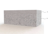
도 7은 제1 영역(A)과 제2 영역(B)을 더욱 명확하게 나타내기 위하여 도 6에 나타낸 다공성 세라믹 폼의 일부를 절단하여 나타낸 도면이다.
도 8 및 도 9는 다공성 세라믹 폼의 또 다른 예를 개략적으로 도시한 도면이다.
도 10은 도 8 및 도 9에 나타낸 다공성 세라믹 폼이 적용된 포집장치를 개략적으로 도시한 부분 분해 사시도이다.
도 11은 도 8 및 도 9에 나타낸 다공성 세라믹 폼이 적용된 포집장치가 브레이크 장치에 결합된 모습의 일 예를 보여주는 도면이다.
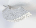
도 12는 실험예 1에서 폴리머 폼으로 사용된 폴리우레탄 폼을 보여주는 사진이다.
도 13은 실험예 1에 따라 폴리머 폼에 세라믹 슬러리가 딥 코팅되어 건조된 모습을 보여주는 사진이다.
도 14는 실험예 1에 따라 제조된 다공성 세라믹 폼을 보여주는 사진이다.
도 15a 내지 도 15c는 실험예 1에 따라 제조된 다공성 세라믹 폼의 미세구조를 보여주는 주사전자현미경(SEM; scanning electron microscope) 사진이다.
도 16은 실험예 2에 따라 휘스커가 형성된 다공성 세라믹 폼을 보여주는 사진이다.
도 17a 내지 도 18d는 실험예 2에 따라 휘스커가 형성된 다공성 세라믹 폼의 미세구조를 보여주는 주사전자현미경(SEM) 사진이다. 1 and 2 are diagrams illustrating an example of a collecting device for collecting fine dust generated from a brake device of a transportation engine.
3 is a view showing an example of a state in which a collecting device is coupled to a brake device.
4 is a diagram schematically illustrating an example of a porous ceramic foam.
5 is a view schematically illustrating an example of a structure in which whiskers protrude from the surface of a wall.
6 is a view schematically showing another example of a porous ceramic foam.
FIG. 7 is a view showing a portion of the porous ceramic foam shown in FIG. 6 being cut to more clearly show the first area (A) and the second area (B).
8 and 9 are views schematically showing another example of a porous ceramic foam.
10 is a partially exploded perspective view schematically illustrating a collecting device to which the porous ceramic foam shown in FIGS. 8 and 9 is applied.
11 is a view showing an example of a state in which the collecting device to which the porous ceramic foam shown in FIGS. 8 and 9 is applied is coupled to a brake device.
12 is a photograph showing polyurethane foam used as a polymer foam in Experimental Example 1.
13 is a photograph showing a state in which a ceramic slurry is dip-coated and dried on a polymer foam according to Experimental Example 1;
14 is a photograph showing a porous ceramic foam prepared according to Experimental Example 1.
15a to 15c are scanning electron microscope (SEM) pictures showing the microstructure of the porous ceramic foam prepared according to Experimental Example 1;
16 is a photograph showing a porous ceramic foam in which whiskers are formed according to Experimental Example 2;
17A to 18D are scanning electron microscope (SEM) photographs showing the microstructure of the porous ceramic foam in which whiskers are formed according to Experimental Example 2;
이하, 첨부된 도면을 참조하여 본 발명에 따른 바람직한 실시예를 상세하게 설명한다. 그러나, 이하의 실시예는 이 기술분야에서 통상적인 지식을 가진 자에게 본 발명이 충분히 이해되도록 제공되는 것으로서 여러 가지 다른 형태로 변형될 수 있으며, 본 발명의 범위가 다음에 기술되는 실시예에 한정되는 것은 아니다. Hereinafter, preferred embodiments according to the present invention will be described in detail with reference to the accompanying drawings. However, the following embodiments are provided to those skilled in the art to sufficiently understand the present invention, and may be modified in various forms, and the scope of the present invention is limited to the following examples. it is not going to be
발명의 상세한 설명 또는 청구범위에서 어느 하나의 구성요소가 다른 구성요소를 "포함"한다고 할 때, 이는 특별히 반대되는 기재가 없는 한 당해 구성요소만으로 이루어지는 것으로 한정되어 해석되지 아니하며, 다른 구성요소를 더 포함할 수 있는 것으로 이해되어야 한다.When it is said that any one component "includes" another component in the detailed description or claims of the invention, it is not construed as being limited to only the corresponding component unless otherwise stated, and other components are not further defined. It should be understood that it can include.
이하에서, 수송기관이라 함은 자동차, 트럭, 버스, 철도차량 뿐만 아니라, 오토바이크 등의 2륜차도 포함하는 의미로 사용한다. 또한, 다공성 세라믹 폼(porous ceramic foam)에서 기공이라 함은 벽체와 벽체 사이의 셀(cell)을 형성하는 기공뿐만 아니라 벽체에 형성된 기공도 포함하는 것으로 사용한다.Hereinafter, the term "transportation" is used to include not only automobiles, trucks, buses, and railroad vehicles, but also two-wheeled vehicles such as motorbikes. Further, in the porous ceramic foam, pores are used to include pores formed in walls as well as pores forming cells between walls.
본 발명의 바람직한 실시예에 따른 포집장치는, 수송기관의 브레이크 장치에서 로터와 브레이크 패드의 마찰에 의해 발생한 미세먼지를 포집하기 위한 장치로서, 상기 로터의 외측면 일부를 감싸는 제1 컬렉터와, 상기 로터의 바깥 둘레면 일부를 감싸는 상부 컬렉터와, 상기 로터의 내측면 일부를 감싸는 제2 컬렉터를 포함하고, 상기 제1 컬렉터와 상기 제2 컬렉터는 다공성 세라믹 폼(porous ceramic foam)으로 이루어진다.A collecting device according to a preferred embodiment of the present invention is a device for collecting fine dust generated by friction between a rotor and a brake pad in a brake device of a transportation engine, comprising: a first collector covering a part of the outer surface of the rotor; An upper collector enclosing a part of the outer circumferential surface of the rotor and a second collector enclosing a part of the inner surface of the rotor, wherein the first collector and the second collector are made of porous ceramic foam.
상기 포집장치는 전체 외관상 U자형으로 구비되어 상기 U자형 내부로 상기 로터를 부분 수용하도록 구성되는 것이 바람직하다.Preferably, the collecting device is provided in a U-shape in overall appearance and is configured to partially accommodate the rotor into the U-shape.
상기 제1 컬렉터는 상기 로터의 외측면과 마주하게 구비되고, 상기 제2 컬렉터는 상기 로터의 내측면과 마주하게 구비되며, 상기 제2 컬렉터는 디스크 형상의 로터를 기준으로 상기 제1 컬렉터가 있는 반대편에 위치되고, 상기 제1 컬렉터와 상기 제2 컬렉터는 상기 로터를 기준으로 서로 마주하게 배치되는 것이 바람직하다.The first collector is provided to face the outer surface of the rotor, the second collector is provided to face the inner surface of the rotor, and the second collector has the first collector with respect to the disk-shaped rotor. It is preferable that the first collector and the second collector face each other with respect to the rotor.
상기 포집장치는 상기 제1 컬렉터를 덮어 보호하고 상기 제1 컬렉터로 유입된 미세먼지가 외부로 유출되는 것을 억제하기 위한 제1 컬렉터 커버와, 상기 제2 컬렉터를 덮어 보호하고 상기 제2 컬렉터로 유입된 미세먼지가 외부로 유출되는 것을 억제하기 위한 제2 컬렉터 커버를 더 포함할 수 있다.The collecting device covers and protects the first collector and includes a first collector cover for preventing fine dust flowing into the first collector from flowing out to the outside, covering and protecting the second collector, and flowing into the second collector. It may further include a second collector cover for suppressing the leakage of fine dust to the outside.
상기 상부 컬렉터를 보호하기 위한 상부 컬렉터 커버가 상기 상부 컬렉터 상부에 더 구비되어 있을 수 있다.An upper collector cover for protecting the upper collector may be further provided above the upper collector.
상기 상부 컬렉터에서 걸러진 깨끗한 공기가 외부로 빠져나갈 수 있도록 상기 상부 컬렉터 커버에 구멍들이 형성되어 있을 수 있다.Holes may be formed in the upper collector cover so that clean air filtered by the upper collector can escape to the outside.
상기 다공성 세라믹 폼은 알루미나(Al2O3), 코디어라이트(cordierite, 2MgO·2Al2O3·5SiO2), 뮬라이트(mullite, 3Al2O3·2SiO2) 및 탄화규소(SiC)로 이루어진 군으로부터 선택된 1종 이상의 세라믹 재질로 이루어질 수 있다.The porous ceramic foam is composed of alumina (Al 2 O 3 ), cordierite (cordierite, 2MgO 2Al 2 O 3 5SiO 2 ), mullite (3Al 2 O 3 2SiO 2 ) and silicon carbide (SiC). It may be made of at least one ceramic material selected from the group.
상기 다공성 세라믹 폼은 기공율이 40∼90%를 이루는 것이 바람직하다.The porous ceramic foam preferably has a porosity of 40 to 90%.
상기 다공성 세라믹 폼은, 미세먼지가 유입되는 통로 역할을 하는 기공(셀(cell))과, 상기 기공(셀(cell)) 사이에서 다공성 세라믹 폼의 골격(strut)을 이루는 벽체를 포함할 수 있으며, 다수의 휘스커가 상기 벽체의 표면에서 기공(셀(cell))을 향해 돌출되어 있을 수 있다.The porous ceramic foam may include pores (cells) serving as a passage through which fine dust flows, and walls forming a strut of the porous ceramic foam between the pores (cells). , A plurality of whiskers may protrude toward pores (cells) from the surface of the wall.
상기 휘스커는 뮬라이트(mullite, 3Al2O3·2SiO2), ZnO 및 탄화규소(SiC)로 이루어진 군으로부터 선택된 1종 이상의 침상형 세라믹 재질로 이루어질 수 있다.The whisker may be made of one or more acicular ceramic materials selected from the group consisting of mullite (3Al 2 O 3 2SiO 2 ), ZnO, and silicon carbide (SiC).
상기 다공성 세라믹 폼은 제2 영역에 비해 상대적으로 작은 크기의 기공들이 분포하는 제1 영역과, 상기 제1 영역에 비해 상대적으로 큰 크기의 기공들이 분포하는 제2 영역을 포함할 수 있고, 상기 제1 영역은 상기 제2 영역에서 포집되는 미세먼지보다 더 작은 크기의 미세먼지를 포집할 수 있다.The porous ceramic foam may include a first region in which pores having a relatively smaller size than the second region are distributed, and a second region in which pores having a relatively larger size than the first region are distributed, and the Area 1 may collect fine dust having a smaller size than the fine dust collected in the second area.
상기 제1 영역보다 상기 제2 영역이 상기 로터에 더 인접하게 위치되는 것이 바람직하다. Preferably, the second area is located closer to the rotor than the first area.
상기 상부 컬렉터는 다공성 세라믹 폼으로 이루어질 수 있다.The upper collector may be made of porous ceramic foam.
상기 제1 컬렉터 및 상기 제2 컬렉터는 돌출된 단턱부를 갖는 다공성 세라믹 폼으로 이루어질 수 있다.The first collector and the second collector may be formed of porous ceramic foam having protruding stepped portions.
상기 다공성 세라믹 폼은 소수성 코팅막으로 도포되어 있고 소수성을 나타낼 수 있다.The porous ceramic foam is coated with a hydrophobic coating film and may exhibit hydrophobicity.
상기 제1 컬렉터와 상기 제2 컬렉터는 사행(serpentine type) 형태로 배열된 리브들과, 리브와 리브 사이의 빈 공간을 이루는 채널을 포함할 수 있다.The first collector and the second collector may include ribs arranged in a serpentine type and a channel forming an empty space between the ribs.
상기 리브들은 곡선형 형태를 이루는 것이 바람직하다.It is preferable that the ribs form a curved shape.
상기 제1 컬렉터와 상기 제2 컬렉터에서, 리브의 단부에는 리브블럭이 구비될 수 있고, 상기 리브블럭은 리브와 리브를 연결하는 매개체이며, 상기 로터와 상기 브레이크 패드의 마찰에 의해 발생한 미세먼지는 상기 채널의 유입구를 통해 유입될 수 있고, 상기 로터의 회전축인 X축에 수직한 Y축 방향으로는 상기 채널의 유입구와 리브블럭 사이의 빈 공간이 상기 채널을 이루는 영역이고, 상기 X축 및 Y축에 수직한 Z축 방향으로는 리브와 리브 사이의 빈 공간이 상기 채널을 이루는 영역일 수 있다.In the first collector and the second collector, a rib block may be provided at an end of the rib, the rib block is a medium connecting the ribs, and the fine dust generated by friction between the rotor and the brake pad It may be introduced through the inlet of the channel, and in the Y-axis direction perpendicular to the X-axis, which is the rotation axis of the rotor, an empty space between the inlet of the channel and the rib block is an area constituting the channel, and the X-axis and Y-axis In the Z-axis direction perpendicular to the axis, an empty space between ribs may be a region constituting the channel.
이하에서, 수송기관의 브레이크 장치에서 발생한 미세먼지를 포집하기 위한 포집장치를 더욱 구체적으로 설명한다. Hereinafter, a collection device for collecting fine dust generated from a brake device of a transportation engine will be described in more detail.
<실시예 1><Example 1>
도 1 및 도 2는 수송기관의 브레이크 장치에서 발생한 미세먼지를 포집하기 위한 포집장치의 일 예를 도시한 도면이다. 도 3은 포집장치가 브레이크 장치에 결합된 모습의 일 예를 보여주는 도면이다. 도 4는 다공성 세라믹 폼의 일 예를 개략적으로 도시한 도면이다.1 and 2 are diagrams illustrating an example of a collecting device for collecting fine dust generated from a brake device of a transportation engine. 3 is a view showing an example of a state in which a collecting device is coupled to a brake device. 4 is a diagram schematically illustrating an example of a porous ceramic foam.
도 1 내지 도 4를 참조하면, 브레이크 장치는 브레이크 패드(brake pad)(20)와 로터(rotor)(10) 사이에 발생하는 마찰에 의해 제동을 수행하는 장치이다. 상기 브레이크 장치는 차축에 연결되어 회전하는 디스크 형상의 로터(10)와, 로터(10)의 회전을 제동하기 위해서 로터(10)에 축 방향(X)(디스크 형상을 이루는 면에 수직한 방향)으로 압력을 가하기 위한 브레이크 패드(20)와, 브레이크 패드(20)를 로터(10)에 밀착시키거나 로터(10)와 접촉된 브레이크 패드(20)를 로터(10)로부터 이격시켜 로터(10)의 회전을 제어하기 위한 브레이크 캘리퍼(brake caliper)(30)를 포함한다. Referring to FIGS. 1 to 4 , the brake device is a device that performs braking by friction generated between a
로터(rotor)(10)는 차축에 연결되어 회전하는 디스크 형상의 장치이다. 로터(10)는 X축에 수직인 제1 디스크면(10a)과, 제1 디스크면에 평행한 제2 디스크면(10b)을 포함할 수 있다. 제1 디스크면(10a)과 제2 디스크면(10b)은 림(rim) 등에 의해 결합되어 있을 수 있다.A rotor (rotor) 10 is a disk-shaped device that is connected to an axle and rotates. The
브레이크 패드(brake pad)(20)는 로터(10)에 축 방향(X 방향)(디스크 형상을 이루는 면에 수직한 방향)으로 압력을 가하여 로터(10)의 회전을 제동하기 위한 장치이다. 브레이크 패드(20)는 제1 디스크면(10a)에 압력을 가하기 위한 제1 패드(미도시)와, 제2 디스크면(10b)에 압력을 가하기 위한 제2 패드(미도시)를 포함할 수 있다. 브레이크 패드(20)는 축 방향(X 방향)을 따라 이동할 수 있도록 브레이크 캘리퍼(brake caliper)(30)에 실장된다. The
브레이크 캘리퍼(30)는 브레이크 패드(20)를 로터(10)에 밀착시키거나 로터(10)와 접촉된 브레이크 패드(20)를 로터(10)로부터 이격시켜 로터(10)의 회전을 제어하기 위한 장치이다. 브레이크 패드(20)는 브레이크 캘리퍼(30) 내부에 수용되고, 제 1 디스크면(10a)을 바라보며 로터(10)와 마주하게 구비되는 제1 패드(미도시)와, 제 2 디스크면(10b)을 바라보며 로터(10)와 마주하게 구비되는 제2 패드(미도시)를 포함할 수 있다. 브레이크 캘리퍼(30)는 로터(10)의 일부를 감싸도록 전체 외관상 U자형으로 구비될 수 있다. The
브레이크 패드(20)와 로터(rotor)(10)의 마찰로 인해 인체에 해로운 미세먼지가 발생한다. 특히, 브레이크 패드(20)의 마모에 의해 발생되는 미세먼지는 입자의 크기가 작아 인체 및 환경에 직접적인 영향을 미칠 수 있다. 특히, 도시지역에서, 교통량의 증가로 인한 브레이크 장치에서 나오는 미립자의 양이 증가하고 있다.Fine dust harmful to the human body is generated due to friction between the
수송기관의 브레이크 장치에서 발생한 미세먼지를 포집하기 위한 포집장치는 마찰에 의해 수백도 이상 표면 온도의 상승이 예상되는 브레이크 패드(20) 주변에 설치되어야 하므로 내열성 확보가 요구되며, 도로변 빗물 및 먼지 등에 의한 장치의 오염과 차량 주행에 따른 진동 발생 등에 대한 내구성이 우수한 필터 소재의 개발이 필요하다.Since the collection device for collecting fine dust generated from the brake device of a transportation engine must be installed around the
NOx와 SOx는 촉매나 자체 발화에 의한 제거가 가능하지만, 브레이크 장치에서 발생하는 미세먼지는 산화가 어려운 조성으로 효과적인 미세먼지 포집이 가능한 소재의 개발과 이를 적용한 부품의 개발, 포집먼지를 제거할 수 있는 차별화된 기술이 적용되어야 한다.NOx and SOx can be removed by a catalyst or self-ignition, but the fine dust generated from the brake system has a composition that is difficult to oxidize, so it is possible to develop a material that can effectively collect fine dust, develop parts to which it is applied, and remove the collected dust. A differentiated technology must be applied.
본 발명의 바람직한 실시예에 따른 포집장치는 브레이크 패드(20)와 로터(10)의 마찰에 의해 발생한 미세먼지(분진)를 포집하는 장치이다. 상기 포집장치는 자동차의 주행 중 브레이킹 시 로터(10)와 브레이크 패드(20)가 접촉되면서 브레이크 패드(20)나 로터(10)가 마모되어 발생되는 미세먼지(분진)을 흡입하여 포집한다. 본 발명의 바람직한 실시예에 따른 포집장치는 교체가 가능하도록 구비될 수 있다. 본 발명의 바람직한 실시예에 따른 포집장치는 어느 정도의 시간 동안 사용 후에 교체하거나 미세먼지를 제거한 후에 재사용이 가능할 수도 있다.A collecting device according to a preferred embodiment of the present invention is a device for collecting fine dust (dust) generated by friction between the
브레이크 패드(20)와 로터(10) 사이의 마찰에서 발생하는 미세먼지를 흡입하기 위해서 포집장치는 브레이크 패드(20)와 브레이크 캘리퍼(30)의 위치에 따라 형상, 설치 위치 등이 변할 수 있다. In order to inhale fine dust generated from friction between the
바람직하게는, 상기 포집장치는 수송기관의 정주행 방향에서 바라볼 때 브레이크 패드(20)의 위치보다 후방(로터의 회전방향에서 볼 때 브페이크 패드 보다 후방)에 설치되는 것이 바람직하다. 브레이크 패드(20)의 위치보다 후방에 포집장치를 설치하는 것은, 수송기관이 정주행 할 때, 브레이크 패드(20)와 로터(10) 사이의 마찰에 의해 발생하는 미세먼지(분진)가 바람 등에 포집장치로 유입되기가 유리하고 더욱 많은 미세먼지를 포집할 수가 있기 때문이다. 수송기관이 정주행 할 때, 브레이크 패드(20)와 로터(10) 사이의 마찰에 의해 발생된 미세먼지(분진)의 대부분은 바람 등에 의해 후방으로 이동하게 되고 브레이크 패드(20)의 위치보다 후방에 설치된 포집장치로 유입되어 포집될 수가 있다. 상기 포집장치는 전원이 없이도 미세먼지를 포집할 수 있게 구비될 수 있다. 자동차가 주행 중 흐르는 공기의 방향(공기의 흐름)에 의해 자연스럽게 미세먼지(분진)가 포집장치로 효율적으로 흡입될 수가 있다.Preferably, the collecting device is preferably installed behind the position of the brake pad 20 (rear than the brake pad when viewed from the direction of rotation of the rotor) when viewed from the forward running direction of the transport engine. Installing the collecting device at the rear of the
상기 포집장치는 로터(10)의 일부를 감싸는 형태로 구비될 수 있다. 상기 포집장치는 로터(10)의 일부를 감싸도록 전체 외관상 U자형으로 구비될 수 있다. 포집장치는 U자형 내부로 로터(10)를 부분 수용하도록 구성된다. The collecting device may be provided in a form surrounding a part of the
상기 포집장치는 로터(10)의 외측면(제1 디스크면(10a)) 일부를 감싸는 제1 컬렉터(collector)(110), 로터(10)의 바깥 둘레면 일부를 감싸는 상부 컬렉터(130), 로터(10)의 내측면(제2 디스크면(10b)) 일부를 감싸는 제2 컬렉터(collector)(120)를 포함할 수 있다. 제1 컬렉터(110)는 로터(10)의 외측면(제1 디스크면(10a))과 마주하게 구비된다. 제2 컬렉터(120)는 로터(10)의 내측면(제2 디스크면(10b))과 마주하게 구비된다. 제2 컬렉터(120)는 디스크 형상의 로터(10)를 기준으로 제1 컬렉터(110)가 있는 반대편에 위치되게 설치된다. 제1 컬렉터(110)와 제2 컬렉터(120)는 로터(10)를 기준으로 서로 마주하게 배치된다. 제1 컬렉터(110)와 제2 컬렉터(120)는 로터(10)와 이격되게 배치된다. The collecting device includes a
상부 컬렉터(130)는 로터(10)의 바깥 둘레면 일부를 감싸도록 구비된다. 상부 컬렉터(130)는 제1 컬렉터(110)와 제2 컬렉터(120)에 연결되어 있을 수 있다. 상부 컬렉터(130)도 로터(10)와 이격되게 설치된다. The
제1 컬렉터(110)와 제2 컬렉터(120)를 보호하고 채널로 유입된 미세먼지가 외부로 유출되는 것을 억제하기 위한 컬렉터 커버(160, 170)가 더 구비될 수도 있다. 컬렉터 커버(160, 170)는 가공성이 양호하고 무게가 가벼운 합성수지, 예컨대 열경화성 합성수지 등의 재질로 이루어질 수 있으나, 금속, 금속합금 등과 같이 내구성이 양호하고 충격에 견딜 수 있는 재료가 사용될 수도 있다. 컬렉터 커버는 제1 컬렉터(110)를 덮어 보호하고 채널로 유입된 미세먼지가 외부로 유출되는 것을 억제하기 위한 제1 컬렉터 커버(160)와, 제2 컬렉터(120)를 덮어 보호하고 채널로 유입된 미세먼지가 외부로 유출되는 것을 억제하기 위한 제2 컬렉터 커버(170)를 포함할 수 있다. 제1 컬렉터 커버(160)는 제1 컬렉터(110)를 기준으로 로터(10)의 반대편에 구비되고, 제2 컬렉터 커버(170)는 제2 컬렉터(120)를 기준으로 로터(10)의 반대편에 구비된다. 컬렉터 커버(160, 170)는 로터(10)로 먼지 등의 이물질이 유입되는 것을 방지하는 역할을 할 수도 있다. Collector covers 160 and 170 may be further provided to protect the
제1 컬렉터 커버(160)는 제1 컬렉터(110)의 측면을 완전히 덮는 형태로 구성되어 있고, 제1 컬렉터(110)의 측면과 밀착되게 구성되어 있을 수 있다. 제2 컬렉터 커버(170)는 제2 컬렉터(120)의 측면을 완전히 덮는 형태로 구성되어 있고, 제2 컬렉터(120)의 측면과 밀착되게 구성되어 있을 수 있다. The
제1 컬렉터 커버(160)에는 제1 컬렉터(110)에서 걸러진 깨끗한 공기가 외부로 빠져나갈 수 있도록 구멍들이 형성되어 있을 수 있다. 로터(10)와 브레이크 패드(20)의 마찰에 의해 발생한 미세먼지는 제1 컬렉터(110)에서 포집되고, 제1 컬렉터(110)를 통과한 깨끗한 공기는 제1 컬렉터 커버(160)의 구멍들을 통해서 배출되도록 함으로써 로터(10)의 주변의 온도가 상승하는 것을 억제할 수 있다. 제2 컬렉터 커버(170)에도 제2 컬렉터(120)에서 걸러진 깨끗한 공기가 외부로 빠져나갈 수 있도록 구멍들이 형성되어 있을 수 있다. 로터(10)와 브레이크 패드(20)의 마찰에 의해 발생한 미세먼지는 제2 컬렉터(120)에서 포집되고, 제2 컬렉터(120)를 통과한 깨끗한 공기는 제2 컬렉터 커버(170)의 구멍들을 통해서 배출되도록 함으로써 로터(10)의 주변의 온도가 상승하는 것을 억제할 수 있다.Holes may be formed in the
상부 컬렉터(130)를 보호하기 위한 상부 컬렉터 커버(180)가 더 구비될 수도 있다. 상부 컬렉터 커버(180)는 가공성이 양호하고 무게가 가벼운 합성수지, 예컨대 열경화성 합성수지 등의 재질로 이루어질 수 있으나, 금속, 금속합금 등과 같이 내구성이 양호하고 충격에 견딜 수 있는 재료가 사용될 수도 있다. 상부 컬렉터 커버(180)는 상부 컬렉터(130) 상부에 구비될 수 있다. 상부 컬렉터 커버(180)는 로터(10)의 바깥 둘레면에 배치되어 로터(10)로 먼지 등의 이물질이 유입되는 것을 방지하는 역할을 할 수도 있다. 상부 컬렉터 커버(180)에는 상부 컬렉터(130)에서 걸러진 깨끗한 공기가 외부로 빠져나갈 수 있도록 구멍들이 형성되어 있을 수 있다. 로터(10)와 브레이크 패드(20)의 마찰에 의해 발생한 미세먼지는 상부 컬렉터(130)에서 포집되고, 상부 컬렉터(130)를 통과한 깨끗한 공기는 상부 컬렉터 커버(180)의 구멍들을 통해서 배출되도록 함으로써 로터(10)의 주변의 온도가 상승하는 것을 억제할 수 있다. An
제1 컬렉터(110)와 제2 컬렉터(120)는 일단에서 타단까지가 직선형인 것으로 이루어질 수도 있고, 더욱 바람직하게는 일단에서 타단까지 곡선형(도 2에서 210 참조)인 것으로 이루어지는 것이 바람직하다. 더욱 바람직하게는 제1 컬렉터(110)와 제2 컬렉터(120)는 디스크 형상을 갖는 로터(10)의 디스크 곡률과 동일하게 곡선형 형태를 이루는 것이 바람직하다. 곡선형 형태를 이루는 제1 컬렉터(110)와 제2 컬렉터(120)의 곡률은 디스크 형상을 갖는 로터(10)의 디스크 곡률(curvature)과 동일한 것이 바람직하다. The
브레이크 패드(20)와 로터(10) 사이의 마찰에 의해 발생하는 미세먼지(분진)는 제1 컬렉터(110)와 제2 컬렉터(120)에 유입된다. 제1 컬렉터(110)와 제2 컬렉터(120)는 다공성 세라믹 폼(porous ceramic foam)으로 이루어진다. 로터(10)와 브레이크 패드(20)의 마찰에 의해 수백도 이상 표면 온도의 상승이 예상되는 로터(10) 주변에 제1 컬렉터(110)와 제2 컬렉터(120)가 설치되므로 내열성 확보가 요구되고, 빗물이나 먼지 등에 의한 오염과 차량 주행에 따른 진동 발생 등에 대하여 내구성이 요구된다. 이러한 점들을 고려하여 제1 컬렉터(110)와 제2 컬렉터(120)는 알루미나(Al2O3), 코디어라이트(cordierite, 2MgO·2Al2O3·5SiO2), 뮬라이트(mullite, 3Al2O3·2SiO2), 탄화규소(SiC) 또는 이들의 혼합물과 같이 내열성을 갖는 다공성 세라믹 폼(세라믹 다공체)으로 이루어지는 것이 바람직하다. 제1 컬렉터(110) 및 제2 컬렉터(120)는 돌출된 단턱부(200)를 갖는 다공성 세라믹 폼으로 이루어질 수 있다.Fine dust (dust) generated by friction between the
상기 다공성 세라믹 폼은 무수히 많은 기공들을 갖는 다공체이다. 상기 다공성 세라믹 폼은 미세먼지가 유입되는 통로 역할을 하는 기공(셀(cell))과, 상기 기공(셀(cell)) 사이에서 다공성 세라믹 폼의 골격(strut)을 이루는 벽체를 포함한다. 다공성 세라믹 폼에서 벽체와 벽체 사이의 큰 기공을 셀(cell)이라고도 하며, 벽체에도 상기 셀보다는 작은 기공들이 형성되어 있으며, 다공성 세라믹 폼에서 기공이라 함은 벽체에 형성된 기공뿐만 아니라 상기 셀도 포함한다.The porous ceramic foam is a porous body having a myriad of pores. The porous ceramic foam includes pores (cells) serving as passages through which fine dust flows, and walls forming struts of the porous ceramic foam between the pores (cells). In the porous ceramic foam, the large pores between the walls are also called cells, and pores smaller than the cells are formed in the walls, and the pores in the porous ceramic foam include the cells as well as the pores formed in the walls. .
상기 다공성 세라믹 폼은 기공율이 40∼90%, 더욱 바람직하게는 60∼85% 정도인 것이 바람직하다. 기공율이 너무 낮을 경우에는 미세먼지 필터링 효율이 낮을 수 있고, 기공율이 너무 높을 경우에는 진동 충격 등에 쉽게 크랙 등의 생기거나 깨지거나 하여 내구성이 저하될 수 있다. 상기 다공성 세라믹 폼에 분포하는 기공(셀) 크기는 50㎛∼2㎜ 정도인 것이 바람직하고, 벽체에 형성되는 기공의 크기는 50㎚∼50㎛ 정도인 것이 바람직하다. The porous ceramic foam preferably has a porosity of about 40 to 90%, more preferably about 60 to 85%. If the porosity is too low, the fine dust filtering efficiency may be low, and if the porosity is too high, cracks or the like may be easily generated or broken due to vibration or impact, and durability may be deteriorated. The size of pores (cells) distributed in the porous ceramic foam is preferably about 50 μm to 2 mm, and the size of pores formed in the wall is preferably about 50 nm to 50 μm.
상기 다공성 세라믹 폼은 표면에 물방울이 맺히는 것을 억제하기 위하여 소수성(hydrophobic) 코팅막으로 도포되어 있을 수 있다. 소수성을 갖게 하기 위하여 다공성 세라믹 재질에 소수성을 갖는 물질을 코팅하여 다공성 세라믹 폼을 제조할 수 있다. 친수성(hydorphilic)을 가질 경우에 다공성 세라믹 폼의 표면에 물방울이 다량으로 맺힐 수 있어서 필터링 효과가 저하될 수 있다. 소수성 코팅막은 10㎚∼2㎛ 정도의 두께로 구비되는 것이 바람직하다. The porous ceramic foam may be coated with a hydrophobic coating film to prevent water droplets from forming on the surface. In order to have hydrophobicity, a porous ceramic foam may be manufactured by coating a material having hydrophobicity on a porous ceramic material. When it has a hydrophilic property, a large amount of water droplets may be formed on the surface of the porous ceramic foam, and the filtering effect may be reduced. The hydrophobic coating film is preferably provided with a thickness of about 10 nm to 2 μm.
소수성 코팅막은 페이스트, 현탁액(suspension) 또는 콜로이드(colloid)를 다공성 세라믹 폼의 외곽 표면에 코팅하고 400∼1000℃ 정도의 온도에서 열처리하여 형성할 수 있다. 소수성 코팅막을 형성하기 위한 예로서 보에마이트-TiO2 졸을 코팅하는 경우를 예로 들수 있다. The hydrophobic coating film may be formed by coating a paste, suspension, or colloid on the outer surface of the porous ceramic form and heat-treating it at a temperature of about 400 to 1000 ° C. As an example for forming a hydrophobic coating film, a case of coating boehmite-TiO 2 sol may be exemplified.
보에마이트-TiO2 졸은 다음과 같이 제조할 수 있다. Boehmite-TiO 2 sol can be prepared as follows.
보에마이트(boehmite)를 증류수 등의 용매에 첨가하고 60℃ 정도의 온도에서 가수분해(hydrolysis) 시키고, 여기에 질산(HNO3) 등의 산(acid)을 첨가하여 용액화(peptization)하여 보에마이트 졸을 형성한다. Boehmite is added to a solvent such as distilled water, hydrolyzed at a temperature of about 60 ° C, and an acid such as nitric acid (HNO 3 ) is added thereto for peptization. form an emite sol.
TiO2 전구체를 증류수 등의 용매에 첨가하고 50℃ 정도의 온도에서 가수분해(hydrolysis) 시키고, 여기에 질산(HNO3) 등의 산(acid)을 첨가하여 용액화(peptization)하여 TiO2 졸을 형성한다. 상기 TiO2 전구체는 TTIP(Titanium isopropoxide) 등일 수 있다.A TiO 2 precursor is added to a solvent such as distilled water, hydrolyzed at a temperature of about 50 ° C, and an acid such as nitric acid (HNO 3 ) is added thereto to peptize the TiO 2 sol. form The TiO 2 precursor may be titanium isopropoxide (TTIP) or the like.
상기 보에마이트 졸과 상기 TiO2 졸을 혼합하여 보에마이트-TiO2 졸을 수득한다. Boehmite-TiO 2 sol is obtained by mixing the boehmite sol and the TiO 2 sol.
상부 컬렉터(130)도 다공성 세라믹 폼으로 이루어질 수 있다. 상부 컬렉터(130)는 알루미나(Al2O3), 코디어라이트(cordierite, 2MgO·2Al2O3·5SiO2), 뮬라이트(mullite, 3Al2O3·2SiO2), 탄화규소(SiC) 또는 이들의 혼합물과 같이 내열성을 갖는 다공성 세라믹 폼으로 이루어지는 것이 바람직하다. 상부 컬렉터(130)는 로터(10)의 바깥 둘레면에 배치되어 로터(10)로 먼지 등의 이물질이 유입되는 것을 방지하는 역할도 한다. The
이하에서, 다공성 세라믹 폼을 제조하는 방법을 구체적으로 설명한다. Hereinafter, a method for manufacturing a porous ceramic foam will be described in detail.
다공성 세라믹 폼를 제조하기 위하여 기판(substrate)으로 다공성의 폴리머 폼(polymer foam)(예컨대, 폴리우레탄 폼(polyurethane foam))을 사용한다. 상기 폴리머 폼은 스펀지(sponge)와 같이 탄성이 있는 다공성 물질이다. 상기 폴리머 폼의 기공율, 기공 크기 등은 이후 제조되는 다공성 세라믹 폼의 기공율, 기공 크기 등에 영향을 미친다. 제조하려는 다공성 세라믹 폼의 형상에 대응되게 폴리머 폼(polymer foam)을 형성한 후 초음파 세척 등을 통해 세척하고 건조한다. 다공성 세라믹 폼이 돌출된 단턱부(200)를 갖는 경우에 폴리머 폼도 단턱부를 갖는 형태로 형성한다. 상기 건조는 폴리머 폼의 용융 온도보다 낮은 30∼90℃ 정도의 오븐(Oven)에서 수행하는 것이 바람직하다. To manufacture a porous ceramic foam, a porous polymer foam (eg, polyurethane foam) is used as a substrate. The polymer foam is an elastic porous material like a sponge. The porosity, pore size, etc. of the polymer foam affect the porosity, pore size, etc. of the porous ceramic foam produced later. After forming a polymer foam to correspond to the shape of the porous ceramic foam to be manufactured, it is washed and dried through ultrasonic cleaning or the like. When the porous ceramic foam has the protruding stepped
세라믹 원료, 바인더 및 용매를 포함하는 출발원료를 준비한다. Prepare starting materials including a ceramic raw material, a binder, and a solvent.
상기 세라믹 원료는 제작할 다공성 세라믹 폼(세라믹 다공체)의 주 소재이다. 상기 세라믹 원료는 알루미나(Al2O3) 분말, 코디어라이트(cordierite, 2MgO·2Al2O3·5SiO2) 분말, 뮬라이트(mullite, 3Al2O3·2SiO2) 분말, 탄화규소(SiC) 분말 또는 이들의 혼합분말 등일 수 있다. 제조되는 다공성 세라믹 폼의 기공율, 기공 크기, 강도 등을 고려하여 상기 세라믹 원료는 10㎚∼40㎛, 더욱 바람직하게는 100㎚∼30㎛인 정도의 평균입경을 갖는 분말을 사용하는 것이 바람직하다. The ceramic raw material is the main material of the porous ceramic form (ceramic porous body) to be produced. The ceramic raw material is alumina (Al 2 O 3 ) powder, cordierite (cordierite, 2MgO 2Al 2 O 3 5SiO 2 ) powder, mullite (3Al 2 O 3 2SiO 2 ) powder, silicon carbide (SiC) It may be a powder or a mixed powder thereof. Considering the porosity, pore size, and strength of the porous ceramic foam to be produced, it is preferable to use powder having an average particle diameter of 10 nm to 40 μm, more preferably 100 nm to 30 μm, as the ceramic raw material.
상기 출발원료는 유리 프릿(Glass frit)을 더 포함할 수 있다. 상기 유리 프릿은 상기 출발원료에 상기 세라믹 원료 100중량부에 대하여 0.01∼45중량부, 더욱 바람직하게는 0.1∼40중량부 정도 함유되는 것이 바람직하다. 상기 유리 프릿은 소결온도를 낮추고, 다공성 세라믹 폼 자체에 Si를 함유시키는 역할을 역할을 할 뿐만 아니라, 휘스커의 성장성을 향상시키는 역할을 할 수 있다. The starting material may further include a glass frit. The glass frit is preferably contained in the starting material in an amount of 0.01 to 45 parts by weight, more preferably 0.1 to 40 parts by weight, based on 100 parts by weight of the ceramic raw material. The glass frit may play a role of lowering a sintering temperature and incorporating Si into the porous ceramic foam itself, and may also play a role of improving whisker growth.
상기 용매(solvent)는 증류수 등일 수 있다. The solvent may be distilled water or the like.
상기 바인더는 폴리비닐알콜(polyvinyl alchol; PVA), 폴리에틸렌글리콜(polyethylene glycol; PEG) 등을 사용할 수 있다. 상기 바인더는 세라믹 슬러리의 접착력을 향상시키는 역할을 한다. 상기 바인더는 상기 출발원료에 상기 세라믹 원료 100중량부에 대하여 1∼50중량부 정도 함유되는 것이 바람직하다. As the binder, polyvinyl alcohol (PVA) or polyethylene glycol (PEG) may be used. The binder serves to improve the adhesive strength of the ceramic slurry. The binder is preferably contained in the starting material in an amount of 1 to 50 parts by weight based on 100 parts by weight of the ceramic raw material.
상기 출발원료는 분산제를 더 포함할 수도 있다. 상기 분산제는 상업적으로 판매되고 있는 물질을 사용할 수 있으며, 그 사용에 특별한 제한이 있는 것은 아니다. 상기 분산제는 출발원료에 상기 세라믹 원료 100중량부에 대하여 0.1∼25중량부 함유되는 것이 바람직하다. The starting material may further include a dispersant. As the dispersant, commercially available materials may be used, and the use thereof is not particularly limited. The dispersant is preferably contained in the starting material in an amount of 0.1 to 25 parts by weight based on 100 parts by weight of the ceramic raw material.
상기 출발원료를 혼합하여 세라믹 슬러리(ceramic slurry)를 형성한다. The starting materials are mixed to form a ceramic slurry.
상기 세라믹 슬러리(ceramic slurry)를 폴리머 폼에 딥 코팅(Dip coating) 한다. 상기 폴리머 폼을 상기 세라믹 슬러리에 완전히 담그고, 진공 분위기에서 딥 코팅을 수행하는 것이 바람직하다. 딥 코팅 후, 폴리머 폼에 함유된 과량의 슬러리를 빼기 위해 외력을 주어 폴리머 폼을 압축했다가 압축을 해제하여 원래의 폴리머 폼 형태로 복귀되게 하고, 이러한 방식에 의해 폴리머 폼에 함유된 일부 슬러리가 폴리머 폼에서 빠져나오게 할 수도 있다.Dip coating the ceramic slurry on the polymer foam. It is preferable to completely immerse the polymer foam in the ceramic slurry and perform dip coating in a vacuum atmosphere. After dip coating, the polymer foam is compressed by applying an external force to remove the excess slurry contained in the polymer foam, and then released to return to the original polymer foam shape. In this way, some of the slurry contained in the polymer foam is It can also be made to come out of the polymer foam.
딥 코팅이 이루어진 폴리머 폼을 건조한다. 상기 건조는 폴리머 폼의 용융 온도보다 낮은 30∼90℃ 정도의 오븐(Oven)에서 수행하는 것이 바람직하다. The polymer foam with the dip coating is dried. The drying is preferably performed in an oven at about 30 to 90° C. lower than the melting temperature of the polymer foam.
딥 코팅이 이루어진 폴리머 폼을 소결한다. 딥 코팅이 이루어진 폴리머 폼을 퍼니스(furnace) 등에 장입하고, 폴리머 폼의 타는 온도보다 높은 제1 온도(예컨대, 400∼800℃)까지 승온시킨 후, 소정 시간 동안 유지하여 폴리머(polymer) 성분이 태워져서 제거되게 하며, 소결온도(예컨대, 1100∼1600℃)까지 승온시킨 후, 상기 소결온도에서 소정 시간 동안 유지하여 소결하여 다공성 세라믹 폼을 얻는다. 상기 세라믹 원료로 알루미나(Al2O3) 분말, 코디어라이트(cordierite, 2MgO·2Al2O3·5SiO2) 분말, 뮬라이트(mullite, 3Al2O3·2SiO2) 분말을 사용한 경우에 상기 소결은 공기(air), 산소(O2)와 같은 산화 분위기에서 수행하는 것이 바람직하며, 상기 세라믹 원료로 탄화규소(SiC) 분말을 사용한 경우에는 환원 분위기에서 수행하는 것이 바람직하다. 상기 소결온도까지는 1∼50℃/min의 승온속도로 상승시키는 것이 바람직한데, 승온 속도가 너무 느린 경우에는 시간이 오래 걸려 생산성이 떨어지고 승온 속도가 너무 빠른 경우에는 급격한 온도 상승에 의해 열적 스트레스가 가해질 수 있으므로 상기 범위의 승온 속도로 온도를 올리는 것이 바람직하다. 소결 공정을 수행한 후, 퍼니스 온도를 하강시키는데, 상기 퍼니스 냉각은 퍼니스 전원을 차단하여 자연적인 상태로 냉각되게 하거나, 임의적으로 온도 하강률(예컨대, 10℃/min)을 설정하여 냉각되게 할 수도 있다. 퍼니스 온도를 하강시키는 동안에도 퍼니스 내부의 압력은 일정하게 유지하는 것이 바람직하다. 상기 소결 공정에서 유기물(또는 폴리머) 성분은 태워져 없어지게 되며, 소결은 유기물 성분이 타는 온도보다 높은 온도에서 이루어지므로 소결 공정이 완료되면 유기물 성분은 모두 제거되게 되며, 폴리머가 위치하는 공간은 기공을 이루고 소결 공정을 거친 소결체는 다공성을 띠게 된다. The polymer foam with dip coating is sintered. The dip-coated polymer form is charged into a furnace, etc., and the temperature is raised to a first temperature (eg, 400 to 800 ° C.) higher than the burning temperature of the polymer form, and then maintained for a predetermined time to burn the polymer component. After the temperature is raised to a sintering temperature (eg, 1100 to 1600° C.), it is maintained at the sintering temperature for a predetermined time and sintered to obtain a porous ceramic foam. Sintering when alumina (Al 2 O 3 ) powder, cordierite (cordierite, 2MgO 2Al 2 O 3 5SiO 2 ) powder, and mullite (3Al 2 O 3 2SiO 2 ) powder are used as the ceramic raw material It is preferable to perform in an oxidizing atmosphere such as air or oxygen (O 2 ), and in the case of using silicon carbide (SiC) powder as the ceramic raw material, it is preferable to perform in a reducing atmosphere. It is preferable to raise the temperature up to the sintering temperature at a rate of 1 to 50 ° C./min. If the rate of temperature increase is too slow, it takes a long time to reduce productivity. If the rate of temperature increase is too fast, thermal stress may be applied due to rapid temperature rise. Therefore, it is preferable to raise the temperature at a temperature increase rate within the above range. After the sintering process is performed, the furnace temperature is lowered. The furnace cooling may be performed by turning off the furnace power to allow cooling in a natural state or by setting a temperature lowering rate (eg, 10° C./min) arbitrarily. there is. It is desirable to keep the pressure inside the furnace constant even while the furnace temperature is lowered. In the sintering process, the organic (or polymer) component is burned away, and since sintering is performed at a temperature higher than the burning temperature of the organic component, when the sintering process is completed, all organic components are removed, and the space where the polymer is located is a pore The sintered body obtained through the sintering process becomes porous.
이렇게 제조된 다공성 세라믹 폼은 무수히 많은 기공들을 갖는 다공체이다. 상기 다공성 세라믹 폼은 미세먼지가 유입되는 통로 역할을 하는 기공(셀(cell))과, 상기 기공(셀(cell)) 사이에서 다공성 세라믹 폼의 골격(strut)을 이루는 벽체를 포함한다. The porous ceramic foam thus prepared is a porous body having a myriad of pores. The porous ceramic foam includes pores (cells) serving as passages through which fine dust flows, and walls forming struts of the porous ceramic foam between the pores (cells).
상기 다공성 세라믹 폼에 휘스커가 형성되어 있을 수도 있다. 더욱 구체적으로, 상기 다공성 세라믹 폼은, 미세먼지가 유입되는 통로 역할을 하는 기공(셀(cell))과, 상기 기공(셀(cell)) 사이에서 다공성 세라믹 폼의 골격(strut)을 이루는 벽체를 포함할 수 있으며, 다수의 휘스커가 상기 벽체의 표면에서 기공(셀(cell))을 향해 돌출되어 있을 수 있다. A whisker may be formed in the porous ceramic foam. More specifically, the porous ceramic foam is composed of pores (cells) serving as a passage through which fine dust flows, and a wall forming a strut of the porous ceramic foam between the pores (cells). may be included, and a plurality of whiskers may protrude toward pores (cells) from the surface of the wall.
상기 휘스커는 뮬라이트(mullite, 3Al2O3·2SiO2), ZnO 및 탄화규소(SiC)로 이루어진 군으로부터 선택된 1종 이상의 침상형 세라믹 재질로 이루어질 수 있다. 상기 휘스커는 사람의 코털에 비유될 수 있고, 기공은 콧구멍에 비유될 수 있으며, 상기 벽체는 코벽(콧구멍을 둘러싸는 코의 부분)에 비유될 수 있다. 사람의 코에 코털이 있으므로 콧구멍으로 유입되는 먼지 등을 더 잘 필터링할 수 있는데, 본 발명의 발명자들은 이러한 점을 고려하여 벽체의 표면으로부터 휘스커가 돌출된 구조를 생각해내었다. 도 5는 벽체의 표면에서 휘스커가 돌출된 구조의 일 예를 개략적으로 도시한 도면이다. 도 5를 참조하면, 다공성 세라믹 폼은 미세먼지가 유입되는 통로 역할을 하는 기공(셀(cell))(112)과, 기공(셀(cell)) 사이에서 다공성 세라믹 폼의 골격(strut)을 이루는 벽체(114)를 포함하며, 다수의 휘스커(116)가 벽체(114)의 표면에서 기공(셀(cell))(112)을 향해 돌출되어 있으며, 이에 따라 미세먼지의 필터링 효과를 극대화할 수가 있다. 상기 휘스커는 필터링시의 차압이 높아지는 것을 억제하면서 미세먼지를 효과적으로 포집하는 역할을 한다.The whisker may be made of one or more acicular ceramic materials selected from the group consisting of mullite (3Al 2 O 3 2SiO 2 ), ZnO, and silicon carbide (SiC). The whisker can be likened to human nose hair, the pore can be likened to a nostril, and the wall can be likened to a nasal wall (the part of the nose surrounding the nostril). Since the human nose has nose hair, it is possible to better filter dust and the like flowing into the nostrils. Considering this point, the inventors of the present invention came up with a structure in which whiskers protrude from the surface of the wall. 5 is a view schematically illustrating an example of a structure in which whiskers protrude from the surface of a wall. Referring to FIG. 5, the porous ceramic foam forms a strut of the porous ceramic foam between pores (cells) 112 serving as passages for fine dust and pores (cells). It includes a
이하에서, 벽체의 표면에서 돌출된 휘스커가 구비된 다공성 세라믹 폼을 제조하는 방법을 설명한다. Hereinafter, a method of manufacturing a porous ceramic foam having whiskers protruding from the surface of a wall will be described.
먼저, 뮬라이트(mullite, 3Al2O3·2SiO2) 재질로 이루어진 휘스커를 다공성 세라믹 폼 표면에 형성하는 방법을 설명한다. First, a method of forming a whisker made of mullite (3Al 2 O 3 2SiO 2 ) on the surface of a porous ceramic foam will be described.
휘스커를 구성하는 성분의 소스 물질, 바인더 및 용매를 포함하는 출발원료를 준비한다. A starting material including a source material, a binder, and a solvent of components constituting the whisker is prepared.
상기 소스 물질은 제조할 휘스커의 주 소재를 구성하는 성분의 소스(source)를 제공하는 역할을 한다. Al 소스로는 알루미나(Alumina), 알루미늄트리부톡사이드(Alumininum tri sec butoxide)과 같은 Al 금속염 등이 사용될 수 있고, Si 소스로는 실리카 졸(Silica sol), TEOS(Tetraethyl orthosilicate), 유리(Glass), 유리 프릿(Glass frit), 플라이애쉬(Fly ash), 장석(Feldspar), 카올린(Kaolin), 점토(Clay), 키아나이트(Kyanite) 등이 사용될 수 있다. 상기 소스 물질은 뮬라이트 분말을 더 포함할 수도 있는데, 상기 뮬라이트 분말은 뮬라이트 결정 성장의 씨드(seed) 역할을 한다. 또한, 소스 물질은 F 소스로 작용하는 AlF3, NH4F와 같은 물질을 더 포함할 수도 있다. The source material serves to provide a source of components constituting the main material of the whisker to be manufactured. As the Al source, Al metal salts such as alumina and aluminum tri-butoxide may be used, and as the Si source, silica sol, TEOS (Tetraethyl orthosilicate), and glass , glass frit, fly ash, feldspar, kaolin, clay, kyanite, and the like may be used. The source material may further include mullite powder, and the mullite powder serves as a seed for mullite crystal growth. In addition, the source material may further include a material such as AlF 3 or NH 4 F serving as an F source.
상기 용매(solvent)는 증류수 등일 수 있다. The solvent may be distilled water or the like.
상기 바인더는 폴리비닐알콜(polyvinyl alchol; PVA), 폴리에틸렌글리콜(polyethylene glycol; PEG) 등을 사용할 수 있다. 상기 바인더는 세라믹 슬러리의 접착력을 향상시키는 역할을 한다. 상기 바인더는 상기 출발원료에 상기 소스 물질 100중량부에 대하여 1∼50중량부 정도 함유되는 것이 바람직하다. As the binder, polyvinyl alcohol (PVA) or polyethylene glycol (PEG) may be used. The binder serves to improve the adhesive strength of the ceramic slurry. The binder is preferably contained in an amount of 1 to 50 parts by weight based on 100 parts by weight of the source material in the starting material.
상기 출발원료는 분산제를 더 포함할 수도 있다. 상기 분산제는 상업적으로 판매되고 있는 물질을 사용할 수 있으며, 그 사용에 특별한 제한이 있는 것은 아니다. 상기 분산제는 출발원료에 상기 소스 물질 100중량부에 대하여 0.1∼25중량부 함유되는 것이 바람직하다. The starting material may further include a dispersant. As the dispersant, commercially available materials may be used, and the use thereof is not particularly limited. The dispersant is preferably contained in the starting material in an amount of 0.1 to 25 parts by weight based on 100 parts by weight of the source material.
상기 출발원료는 증점제를 더 포함할 수도 있다. 상기 분산제는 상업적으로 판매되고 있는 물질을 사용할 수 있으며, 그 사용에 특별한 제한이 있는 것은 아니다. 상기 증점제는 후술하는 세라믹 슬러리의 점도를 높여 침전속도를 감소시키는 역할을 한다. 상기 증점제는 출발원료에 상기 소스 물질 100중량부에 대하여 0.1∼25중량부 함유되는 것이 바람직하다. The starting material may further include a thickening agent. As the dispersant, commercially available materials may be used, and the use thereof is not particularly limited. The thickener increases the viscosity of the ceramic slurry to be described later and serves to reduce the settling rate. The thickener is preferably contained in the starting material in an amount of 0.1 to 25 parts by weight based on 100 parts by weight of the source material.
상기 출발원료를 혼합하여 세라믹 슬러리(ceramic slurry)를 형성한다. The starting materials are mixed to form a ceramic slurry.
상기 세라믹 슬러리(ceramic slurry)를 다공성 세라믹 폼에 딥 코팅(Dip coating) 한다. 상기 다공성 세라믹 폼을 상기 세라믹 슬러리에 완전히 담그고, 진공 분위기에서 딥 코팅을 수행하는 것이 바람직하다. Dip coating the ceramic slurry on a porous ceramic foam. It is preferable to completely immerse the porous ceramic foam in the ceramic slurry and perform dip coating in a vacuum atmosphere.
딥 코팅이 이루어진 다공성 세라믹 폼을 건조한다. 상기 건조는 30∼90℃ 정도의 오븐(Oven)에서 수행하는 것이 바람직하다. The porous ceramic foam with dip coating is dried. The drying is preferably performed in an oven at about 30 to 90 ° C.
딥 코팅이 이루어진 다공성 세라믹 폼을 소결한다. 딥 코팅이 이루어진 다공성 세라믹 폼을 퍼니스(furnace) 등에 장입하고, 소결온도(예컨대, 1100∼1600℃)까지 승온시킨 후, 상기 소결온도에서 소정 시간 동안 유지하여 소결하여 휘스커가 형성된 다공성 세라믹 폼을 얻는다. 상기 소결은 공기(air), 산소(O2)와 같은 산화 분위기에서 수행하는 것이 바람직하다. 상기 소결온도까지는 1∼50℃/min의 승온속도로 상승시키는 것이 바람직한데, 승온 속도가 너무 느린 경우에는 시간이 오래 걸려 생산성이 떨어지고 승온 속도가 너무 빠른 경우에는 급격한 온도 상승에 의해 열적 스트레스가 가해질 수 있으므로 상기 범위의 승온 속도로 온도를 올리는 것이 바람직하다. 소결 공정을 수행한 후, 퍼니스 온도를 하강시키는데, 상기 퍼니스 냉각은 퍼니스 전원을 차단하여 자연적인 상태로 냉각되게 하거나, 임의적으로 온도 하강률(예컨대, 10℃/min)을 설정하여 냉각되게 할 수도 있다. 퍼니스 온도를 하강시키는 동안에도 퍼니스 내부의 압력은 일정하게 유지하는 것이 바람직하다. 상기 소결 공정에서 유기물(또는 폴리머) 성분은 태워져 없어지게 되며, 소결은 유기물 성분이 타는 온도보다 높은 온도에서 이루어지므로 소결 공정이 완료되면 유기물 성분은 모두 제거되게 된다. The porous ceramic foam with dip coating is sintered. The porous ceramic foam having the dip coating is charged into a furnace, etc., heated up to a sintering temperature (eg, 1100 to 1600° C.), maintained at the sintering temperature for a predetermined time, and then sintered to obtain a porous ceramic foam with whiskers. . The sintering is preferably performed in an oxidizing atmosphere such as air or oxygen (O 2 ). It is preferable to raise the temperature up to the sintering temperature at a rate of 1 to 50 ° C./min. If the rate of temperature increase is too slow, it takes a long time to reduce productivity. If the rate of temperature increase is too fast, thermal stress may be applied due to rapid temperature rise. Therefore, it is preferable to raise the temperature at a temperature increase rate within the above range. After the sintering process is performed, the furnace temperature is lowered. The furnace cooling may be performed by turning off the furnace power to allow cooling in a natural state or by setting a temperature lowering rate (eg, 10° C./min) arbitrarily. there is. It is desirable to keep the pressure inside the furnace constant even while the furnace temperature is lowered. In the sintering process, organic (or polymer) components are burned away, and since sintering is performed at a temperature higher than the burning temperature of the organic components, all organic components are removed when the sintering process is completed.
이렇게 제조된 다공성 세라믹 폼은 무수히 많은 기공들을 갖는 다공체로서, 미세먼지가 유입되는 통로 역할을 하는 기공(셀(cell))과, 상기 기공(셀(cell)) 사이에서 다공성 세라믹 폼의 골격(strut)을 이루는 벽체를 포함하며, 다수의 뮬라이트 휘스커가 상기 벽체의 표면에서 기공(셀(cell))을 향해 돌출되어 있다. The porous ceramic foam thus prepared is a porous body having a myriad of pores, and between the pores (cells) serving as passages for fine dust, and the pores (cells), the framework (strut) of the porous ceramic foam is formed. ), and a plurality of mullite whiskers protrude from the surface of the wall toward pores (cells).
이하에서, ZnO 재질로 이루어진 휘스커를 다공성 세라믹 폼 표면에 형성하는 방법을 설명한다. Hereinafter, a method of forming whiskers made of ZnO on the surface of a porous ceramic foam will be described.
용매에 휘스커를 구성하는 성분의 소스 물질을 혼합하여 씨드 용액(seed solution)을 형성한다. 상기 소스 물질은 제조할 휘스커의 주 소재인 ZnO를 구성하는 성분의 소스(source)를 제공하는 역할을 한다. 상기 소스 물질로는 Zn의 소스(source) 역할을 하는 질산아연 6수화물(zinc nitrate hexahydrate; Zn(NO3)2·6H2O) 등을 사용할 수 있다. 상기 용매는 에탄올과 같은 알콜 등일 수 있다.A seed solution is formed by mixing source materials of components constituting the whisker with a solvent. The source material serves to provide a source of components constituting ZnO, which is the main material of the whisker to be manufactured. As the source material, zinc nitrate hexahydrate (Zn(NO 3 ) 2 6H 2 O) or the like serving as a source of Zn may be used. The solvent may be an alcohol such as ethanol or the like.
상기 씨드 용액을 다공성 세라믹 폼에 딥 코팅(Dip coating) 한다. 상기 다공성 세라믹 폼을 상기 씨드 용액에 완전히 담그고, 진공 분위기에서 딥 코팅을 수행하는 것이 바람직하다. The seed solution is dip coated on the porous ceramic foam. It is preferable to completely immerse the porous ceramic foam in the seed solution and perform dip coating in a vacuum atmosphere.
딥 코팅이 이루어진 다공성 세라믹 폼을 어닐링(annealing) 한다. 상기 어닐링에 의해 씨드 용액이 다공성 세라믹 폼에 잘 접착될 수가 있다. 상기 어닐링은 120∼300℃ 정도의 오븐(Oven)에서 수행하는 것이 바람직하다. The porous ceramic foam on which the dip coating is made is annealed. The seed solution can be well adhered to the porous ceramic foam by the annealing. The annealing is preferably performed in an oven at about 120 to 300 °C.
휘스커를 구성하는 성분의 소스 물질, 성장촉진제, 바인더 및 용매를 포함하는 출발원료를 준비한다. Starting materials including source materials, growth promoters, binders, and solvents constituting whiskers are prepared.
상기 소스 물질은 제조할 휘스커의 주 소재인 ZnO를 구성하는 성분의 소스(source)를 제공하는 역할을 한다. 상기 소스 물질로는 Zn의 소스(source) 역할을 하는 질산아연 6수화물(zinc nitrate hexahydrate; Zn(NO3)2·6H2O) 등을 사용할 수 있다. The source material serves to provide a source of components constituting ZnO, which is the main material of the whisker to be manufactured. As the source material, zinc nitrate hexahydrate (Zn(NO 3 ) 2 6H 2 O) or the like serving as a source of Zn may be used.
상기 성장촉진제는 헥사메틸렌테트라민(Hexamethylenetetramine) 분말 등을 사용할 수 있다. 상기 성장촉진제는 상기 출발원료에 상기 소스 물질 100중량부에 대하여 50∼200중량부 정도 함유되는 것이 바람직하다. As the growth promoter, hexamethylenetetramine powder or the like may be used. The growth promoter is preferably contained in the starting material in an amount of about 50 to 200 parts by weight based on 100 parts by weight of the source material.
상기 바인더는 폴리비닐알콜(polyvinyl alchol; PVA), 폴리에틸렌글리콜(polyethylene glycol; PEG) 등을 사용할 수 있다. 상기 바인더는 세라믹 슬러리의 접착력을 향상시키는 역할을 한다. 상기 바인더는 상기 출발원료에 상기 소스 물질 100중량부에 대하여 1∼50중량부 정도 함유되는 것이 바람직하다. As the binder, polyvinyl alcohol (PVA) or polyethylene glycol (PEG) may be used. The binder serves to improve the adhesive strength of the ceramic slurry. The binder is preferably contained in an amount of 1 to 50 parts by weight based on 100 parts by weight of the source material in the starting material.
상기 용매는 에탄올과 같은 알콜 등일 수 있다.The solvent may be an alcohol such as ethanol or the like.
상기 출발원료를 혼합하여 성장 용액을 형성한다. The starting materials are mixed to form a growth solution.
상기 성장 용액을 어닐링이 이루어진 다공성 세라믹 폼에 딥 코팅(Dip coating) 한다. 상기 다공성 세라믹 폼을 상기 성장 용액에 완전히 담그고, 진공 분위기에서 딥 코팅을 수행하는 것이 바람직하다. The growth solution is dip coated on the annealed porous ceramic foam. It is preferable to completely immerse the porous ceramic foam in the growth solution and perform dip coating in a vacuum atmosphere.
성장 용액으로 딥 코팅이 이루어진 다공성 세라믹 폼을 다공성 세라믹 폼을 소결한다. 성장 용액으로 딥 코팅이 이루어진 다공성 세라믹 폼을 퍼니스(furnace) 등에 장입하고, 소결온도(예컨대, 1000∼1500℃)까지 승온시킨 후, 상기 소결온도에서 소정 시간 동안 유지하여 소결하여 휘스커가 형성된 다공성 세라믹 폼을 얻는다. 상기 소결은 공기(air), 산소(O2)와 같은 산화 분위기에서 수행하는 것이 바람직하다. 상기 소결온도까지는 1∼50℃/min의 승온속도로 상승시키는 것이 바람직한데, 승온 속도가 너무 느린 경우에는 시간이 오래 걸려 생산성이 떨어지고 승온 속도가 너무 빠른 경우에는 급격한 온도 상승에 의해 열적 스트레스가 가해질 수 있으므로 상기 범위의 승온 속도로 온도를 올리는 것이 바람직하다. 소결 공정을 수행한 후, 퍼니스 온도를 하강시키는데, 상기 퍼니스 냉각은 퍼니스 전원을 차단하여 자연적인 상태로 냉각되게 하거나, 임의적으로 온도 하강률(예컨대, 10℃/min)을 설정하여 냉각되게 할 수도 있다. 퍼니스 온도를 하강시키는 동안에도 퍼니스 내부의 압력은 일정하게 유지하는 것이 바람직하다. 상기 소결 공정에서 유기물(또는 폴리머) 성분은 태워져 없어지게 되며, 소결은 유기물 성분이 타는 온도보다 높은 온도에서 이루어지므로 소결 공정이 완료되면 유기물 성분은 모두 제거되게 된다. The porous ceramic foam, which is dip-coated with the growth solution, is sintered. After the porous ceramic form dip-coated with the growth solution is charged into a furnace, the temperature is raised to a sintering temperature (eg, 1000 to 1500° C.), and then maintained at the sintering temperature for a predetermined time to sinter the porous ceramic form with whiskers. get the form The sintering is preferably performed in an oxidizing atmosphere such as air or oxygen (O 2 ). It is preferable to raise the temperature up to the sintering temperature at a rate of 1 to 50 ° C./min. If the rate of temperature increase is too slow, it takes a long time to reduce productivity. If the rate of temperature increase is too fast, thermal stress may be applied due to rapid temperature rise. Therefore, it is preferable to raise the temperature at a temperature increase rate within the above range. After the sintering process is performed, the furnace temperature is lowered. The furnace cooling may be performed by turning off the furnace power to allow cooling in a natural state or by setting a temperature lowering rate (eg, 10° C./min) arbitrarily. there is. It is desirable to keep the pressure inside the furnace constant even while the furnace temperature is lowered. In the sintering process, organic (or polymer) components are burned away, and since sintering is performed at a temperature higher than the burning temperature of the organic components, all organic components are removed when the sintering process is completed.
이렇게 제조된 다공성 세라믹 폼은 무수히 많은 기공들을 갖는 다공체로서, 미세먼지가 유입되는 통로 역할을 하는 기공(셀(cell))과, 상기 기공(셀(cell)) 사이에서 다공성 세라믹 폼의 골격(strut)을 이루는 벽체를 포함하며, 다수의 ZnO 휘스커가 상기 벽체의 표면에서 기공(셀(cell))을 향해 돌출되어 있다. The porous ceramic foam thus prepared is a porous body having a myriad of pores, and between the pores (cells) serving as passages for fine dust, and the pores (cells), the framework (strut) of the porous ceramic foam is formed. ), and a plurality of ZnO whiskers protrude toward pores (cells) from the surface of the wall.
이하에서, SiC 재질로 이루어진 휘스커를 다공성 세라믹 폼 표면에 형성하는 방법을 설명한다. Hereinafter, a method of forming whiskers made of SiC material on the surface of the porous ceramic foam will be described.
다공성 세라믹 폼을 튜브로 등의 성장장치에 장입한다. 휘스커(whisker) 성장의 소스로 사용될 실리카 분말(Silica powder)과 카본 분말(Carbon powder)을 준비한다. 상기 실리카 분말(Silica powder)과 카본 분말(Carbon powder)은 1:1 내지 1:2의 중량비를 이루게 하는 것이 바람직하다. 성장장치 내의 온도를 반응온도(예컨대, 1350∼1600℃)로 상승시키고, 캐리어 가스(Carrier gas)를 이용하여 실리카 분말(Silica powder)과 카본 분말(Carbon powder)을 성장장치로 유입되게 하여 다공성 세라믹 폼 표면에서 SiC 휘스커가 성장되게 한다. The porous ceramic foam is loaded into a growth device such as a tube furnace. Prepare silica powder and carbon powder to be used as sources for whisker growth. Preferably, the weight ratio of the silica powder and the carbon powder is 1:1 to 1:2. The temperature in the growth device is raised to the reaction temperature (eg, 1350 to 1600 ° C.), and silica powder and carbon powder are introduced into the growth device using a carrier gas to produce a porous ceramic Allow SiC whiskers to grow on the foam surface.
이렇게 제조된 다공성 세라믹 폼은 무수히 많은 기공들을 갖는 다공체로서, 미세먼지가 유입되는 통로 역할을 하는 기공(셀(cell))과, 상기 기(셀(cell))공 사이에서 다공성 세라믹 폼의 골격(strut)을 이루는 벽체를 포함하며, 다수의 SiC 휘스커가 상기 벽체의 표면에서 기공(셀(cell))을 향해 돌출되어 있다. The porous ceramic foam thus prepared is a porous body having a myriad of pores, and between the pores (cells) serving as passages for fine dust, and the pores (cells), the skeleton of the porous ceramic foam ( It includes a wall forming a strut, and a plurality of SiC whiskers protrude toward pores (cells) from the surface of the wall.
다공성 세라믹 폼을 제조하는 방법과 다공성 세라믹 폼에 휘스커를 형성하는 방법을 설명하였으나, 다공성 세라믹 폼의 제조 방법과 휘스커의 형성 방법은 다양할 수 있으며 상술한 예들에 한정되는 것은 아니다.Although the method of manufacturing the porous ceramic foam and the method of forming the whisker in the porous ceramic form have been described, the method of manufacturing the porous ceramic form and the method of forming the whisker may vary and are not limited to the above examples.
상부 컬렉터(130)는 상술한 다공성 세라믹 폼으로 이루어질 수도 있지만, 세라믹 섬유가 네트워크 형태로 얽혀있는 세라믹 섬유 필터로 이루어질 수도 있다. 이 경우, 상부 컬렉터(130)에 분포하는 기공들은 50㎚∼10㎛의 평균 크기를 갖는 것이 바람직하다. 상기 세라믹 섬유는 알루미나(Al2O3), 코디어라이트(cordierite, 2MgO·2Al2O3·5SiO2), 뮬라이트(mullite, 3Al2O3·2SiO2), 탄화규소(SiC) 또는 이들의 혼합물과 같이 내열성을 갖는 세라믹 재질로 이루어지는 것이 바람직하다. The
세라믹 섬유 재질의 상부 컬렉터(130)는 세라믹 섬유를 전기방사하여 제조하는 등의 방법으로 제조할 수 있다. 예컨대, 세라믹 섬유를 포함하는 용액을 전압차 1∼100kV, 방사 유속 0.1∼10㎖/hr, 방사 거리 2∼50㎝, 노즐의 구멍 크기 0.01∼2.0㎜의 조건으로 전기방사를 실시하여 세라믹 섬유가 네트워크 형태로 얽혀있는 세라믹 섬유 필터를 제조할 수 있다. The
<실시예 2><Example 2>
포집장치의 구성은 상기 실시예 1과 동일하고, 제1 컬렉터(110), 제2 컬렉터(120) 또는 상부 컬렉터(130)를 구성하는 다공성 세라믹 폼만이 다르게 구성되며, 따라서 포집장치에 대한 설명은 생략한다. 이하에서, 실시예 1에서와 다른 다공성 세라믹 폼에 대하여만 설명한다. The configuration of the collecting device is the same as that of the first embodiment, and only the porous ceramic foam constituting the
제1 컬렉터(110)와 제2 컬렉터(120)는 다공성 세라믹 폼(porous ceramic foam)으로 이루어진다. 제1 컬렉터(110)와 제2 컬렉터(120)는 알루미나(Al2O3), 코디어라이트(cordierite, 2MgO·2Al2O3·5SiO2), 뮬라이트(mullite, 3Al2O3·2SiO2), 탄화규소(SiC) 또는 이들의 혼합물과 같이 내열성을 갖는 다공성 세라믹 폼으로 이루어지는 것이 바람직하다. 제1 컬렉터(110) 및 제2 컬렉터(120)는 돌출된 단턱부(200)를 갖는 다공성 세라믹 폼으로 이루어질 수 있다.The
상기 다공성 세라믹 폼은 기공율이 40∼90%, 더욱 바람직하게는 60∼85% 정도인 것이 바람직하다. 기공율이 너무 낮을 경우에는 미세먼지 필터링 효율이 낮을 수 있고, 기공율이 너무 높을 경우에는 진동 충격 등에 쉽게 크랙 등의 생기거나 깨지거나 하여 내구성이 저하될 수 있다. 상기 다공성 세라믹 폼에 분포하는 기공(셀) 크기는 50㎛∼2㎜ 정도인 것이 바람직하고, 벽체에 형성되는 기공의 크기는 50㎚∼50㎛ 정도인 것이 바람직하다.The porous ceramic foam preferably has a porosity of about 40 to 90%, more preferably about 60 to 85%. If the porosity is too low, the fine dust filtering efficiency may be low, and if the porosity is too high, cracks or the like may be easily generated or broken due to vibration or impact, and durability may be deteriorated. The size of pores (cells) distributed in the porous ceramic foam is preferably about 50 μm to 2 mm, and the size of pores formed in the wall is preferably about 50 nm to 50 μm.
상부 컬렉터(130)도 다공성 세라믹 폼으로 이루어질 수 있다. 상부 컬렉터(130)는 알루미나(Al2O3), 코디어라이트(cordierite, 2MgO·2Al2O3·5SiO2), 뮬라이트(mullite, 3Al2O3·2SiO2), 탄화규소(SiC) 또는 이들의 혼합물과 같이 내열성을 갖는 다공성 세라믹 폼으로 이루어지는 것이 바람직하다. 상부 컬렉터(130)는 로터(10)의 바깥 둘레면에 배치되어 로터(10)로 먼지 등의 이물질이 유입되는 것을 방지하는 역할도 한다. The
상기 다공성 세라믹 폼은 무수히 많은 기공들을 갖는 다공체이다. 상기 다공성 세라믹 폼은 미세먼지가 유입되는 통로 역할을 하는 기공(셀(cell))과, 상기 기공(셀(cell)) 사이에서 다공성 세라믹 폼의 골격(strut)을 이루는 벽체를 포함한다. The porous ceramic foam is a porous body having a myriad of pores. The porous ceramic foam includes pores (cells) serving as passages through which fine dust flows, and walls forming struts of the porous ceramic foam between the pores (cells).
상기 다공성 세라믹 폼은 제2 영역(B)에 비해 상대적으로 작은 크기의 기공들이 분포하는 제1 영역(A)과, 제1 영역(A)에 비해 상대적으로 큰 크기의 기공들이 분포하는 제2 영역(B)을 포함한다. The porous ceramic foam includes a first region (A) in which pores having a relatively small size compared to the second region (B) are distributed, and a second region in which pores having a relatively large size compared to the first region (A) are distributed. (B) is included.
도 6은 제2 영역(B)에 비해 상대적으로 작은 크기의 기공들이 분포하는 제1 영역(A)과, 제 영역(A)에 비해 상대적으로 큰 크기의 기공들이 분포하는 제2 영역(B)을 포함하는 다공성 세라믹 폼을 개략적으로 도시한 도면이고, 도 7은 제1 영역(A)과 제2 영역(B)을 더욱 명확하게 나타내기 위하여 도 6에 나타낸 다공성 세라믹 폼의 일부를 절단하여 나타낸 도면이다. 6 shows a first area (A) in which pores of a relatively small size compared to the second area (B) are distributed, and a second area (B) in which pores of a relatively large size are distributed compared to the first area (A). 7 is a view schematically showing a porous ceramic foam including a, and FIG. 7 is a view showing a part of the porous ceramic foam shown in FIG. 6 cut to more clearly show the first area (A) and the second area (B). it is a drawing
도 6 및 도 7을 참조하면, 상기 다공성 세라믹 폼은 제2 영역(B)에 비해 상대적으로 작은 크기의 기공들(제1 크기의 기공들)이 분포하는 제1 영역(A)과, 제1 영역(A)에 비해 상대적으로 큰 크기의 기공들(제2 크기의 기공들)이 분포하는 제2 영역(B)을 포함할 수 있고, 제1 영역(A)은 제2 영역(B)에서 포집되는 미세먼지보다 더 작은 크기의 미세먼지를 포집할 수 있다. 제2 크기의 기공들은 제1 크기의 기공들보다 평균입경이 크고, 제1 영역(A)보다 제2 영역(B)이 상기 로터에 더 인접하게 위치되는 것이 바람직하다. Referring to FIGS. 6 and 7 , the porous ceramic foam includes a first area (A) in which pores (pores of a first size) are distributed that are relatively smaller than those of the second area (B), and a first It may include a second area (B) in which pores (pores of a second size) relatively larger than area (A) are distributed, and the first area (A) is formed in the second area (B). It can collect fine dust of a smaller size than the collected fine dust. It is preferable that the pores of the second size have a larger average particle diameter than the pores of the first size, and the second region (B) is located closer to the rotor than the first region (A).
제1 영역(A)과 제2 영역(B)을 포함하는 다공성 세라믹 폼은 표면에 물방울이 맺히는 것을 억제하기 위하여 소수성(hydrophobic) 코팅막으로 도포되어 있을 수 있다. 소수성을 갖게 하기 위하여 다공성 세라믹 재질에 소수성을 갖는 물질을 코팅하여 다공성 세라믹 폼을 제조할 수 있다. 친수성(hydorphilic)을 가질 경우에 다공성 세라믹 폼의 표면에 물방울이 다량으로 맺힐 수 있어서 필터링 효과가 저하될 수 있다. 소수성 코팅막은 10㎚∼2㎛ 정도의 두께로 구비되는 것이 바람직하다. The porous ceramic foam including the first region (A) and the second region (B) may be coated with a hydrophobic coating film to prevent water droplets from forming on the surface. In order to have hydrophobicity, a porous ceramic foam may be manufactured by coating a material having hydrophobicity on a porous ceramic material. When it has a hydrophilic property, a large amount of water droplets may be formed on the surface of the porous ceramic foam, and the filtering effect may be reduced. The hydrophobic coating film is preferably provided with a thickness of about 10 nm to 2 μm.
이하에서, 제1 영역(A)과 제2 영역(B)을 포함하는 다공성 세라믹 폼을 제조하는 방법을 설명한다. Hereinafter, a method of manufacturing a porous ceramic form including the first region (A) and the second region (B) will be described.
다공성 세라믹 폼를 제조하기 위하여 기판(substrate)으로 다공성의 폴리머 폼(polymer foam)(예컨대, 폴리우레탄 폼(polyurethane foam))을 사용한다. 상기 폴리머 폼은 스펀지(sponge)와 같이 탄성이 있는 다공성 물질이다. 상기 폴리머 폼의 기공율, 기공 크기 등은 이후 제조되는 다공성 세라믹 폼의 기공율, 기공 크기 등에 영향을 미친다. 제조하려는 다공성 세라믹 폼의 형상에 대응되게 폴리머 폼(polymer foam)을 자른 후 초음파 세척 등을 통해 세척하고 건조한다. 상기 건조는 폴리머 폼의 용융 온도보다 낮은 30∼90℃ 정도의 오븐(Oven)에서 수행하는 것이 바람직하다. To manufacture a porous ceramic foam, a porous polymer foam (eg, polyurethane foam) is used as a substrate. The polymer foam is an elastic porous material like a sponge. The porosity, pore size, etc. of the polymer foam affect the porosity, pore size, etc. of the porous ceramic foam produced later. After cutting the polymer foam to correspond to the shape of the porous ceramic foam to be manufactured, it is washed and dried through ultrasonic cleaning. The drying is preferably performed in an oven at about 30 to 90° C. lower than the melting temperature of the polymer foam.
세라믹 원료, 바인더 및 용매를 포함하는 출발원료를 준비한다. Prepare starting materials including a ceramic raw material, a binder, and a solvent.
상기 세라믹 원료는 제작할 다공성 세라믹 폼(세라믹 다공체)의 주 소재이다. 상기 세라믹 원료는 알루미나(Al2O3) 분말, 코디어라이트(cordierite, 2MgO·2Al2O3·5SiO2) 분말, 뮬라이트(mullite, 3Al2O3·2SiO2) 분말, 탄화규소(SiC) 분말 또는 이들의 혼합분말 등일 수 있다. 제조되는 다공성 세라믹 폼의 기공율, 기공 크기, 강도 등을 고려하여 상기 세라믹 원료는 10㎚∼40㎛, 더욱 바람직하게는 100㎚∼30㎛인 정도의 평균입경을 갖는 분말을 사용하는 것이 바람직하다. The ceramic raw material is the main material of the porous ceramic form (ceramic porous body) to be produced. The ceramic raw material is alumina (Al 2 O 3 ) powder, cordierite (cordierite, 2MgO 2Al 2 O 3 5SiO 2 ) powder, mullite (3Al 2 O 3 2SiO 2 ) powder, silicon carbide (SiC) It may be a powder or a mixed powder thereof. Considering the porosity, pore size, and strength of the porous ceramic foam to be produced, it is preferable to use powder having an average particle diameter of 10 nm to 40 μm, more preferably 100 nm to 30 μm, as the ceramic raw material.
상기 출발원료는 유리 프릿(Glass frit)을 더 포함할 수 있다. 상기 유리 프릿은 상기 출발원료에 상기 세라믹 원료 100중량부에 대하여 0.01∼45중량부, 더욱 바람직하게는 0.1∼40중량부 정도 함유되는 것이 바람직하다. 상기 유리 프릿은 소결온도를 낮추고, 다공성 세라믹 폼 자체에 Si를 함유시키는 역할을 역할을 할 뿐만 아니라, 휘스커의 성장성을 향상시키는 역할을 할 수 있다. The starting material may further include a glass frit. The glass frit is preferably contained in the starting material in an amount of 0.01 to 45 parts by weight, more preferably 0.1 to 40 parts by weight, based on 100 parts by weight of the ceramic raw material. The glass frit may play a role of lowering a sintering temperature and incorporating Si into the porous ceramic foam itself, and may also play a role of improving whisker growth.
상기 용매(solvent)는 증류수 등일 수 있다. The solvent may be distilled water or the like.
상기 바인더는 폴리비닐알콜(polyvinyl alchol; PVA), 폴리에틸렌글리콜(polyethylene glycol; PEG) 등을 사용할 수 있다. 상기 바인더는 세라믹 슬러리의 접착력을 향상시키는 역할을 한다. 상기 바인더는 상기 출발원료에 상기 세라믹 원료 100중량부에 대하여 1∼50중량부 정도 함유되는 것이 바람직하다. As the binder, polyvinyl alcohol (PVA) or polyethylene glycol (PEG) may be used. The binder serves to improve the adhesive strength of the ceramic slurry. The binder is preferably contained in the starting material in an amount of 1 to 50 parts by weight based on 100 parts by weight of the ceramic raw material.
상기 출발원료는 분산제를 더 포함할 수도 있다. 상기 분산제는 상업적으로 판매되고 있는 물질을 사용할 수 있으며, 그 사용에 특별한 제한이 있는 것은 아니다. 상기 분산제는 출발원료에 상기 세라믹 원료 100중량부에 대하여 0.1∼25중량부 함유되는 것이 바람직하다. The starting material may further include a dispersant. As the dispersant, commercially available materials may be used, and the use thereof is not particularly limited. The dispersant is preferably contained in the starting material in an amount of 0.1 to 25 parts by weight based on 100 parts by weight of the ceramic raw material.
상기 출발원료를 혼합하여 세라믹 슬러리(ceramic slurry)를 형성한다. The starting materials are mixed to form a ceramic slurry.
상기 세라믹 슬러리(ceramic slurry)를 폴리머 폼에 딥 코팅(Dip coating) 한다. 상기 폴리머 폼을 상기 세라믹 슬러리에 완전히 담그고, 진공 분위기에서 딥 코팅을 수행하는 것이 바람직하다. 딥 코팅 후, 폴리머 폼에 함유된 과량의 슬러리를 빼기 위해 외력을 주어 폴리머 폼을 압축했다가 압축을 해제하여 원래의 폴리머 폼 형태로 복귀되게 하고, 이러한 방식에 의해 폴리머 폼에 함유된 일부 슬러리가 폴리머 폼에서 빠져나오게 할 수도 있다.Dip coating the ceramic slurry on the polymer foam. It is preferable to completely immerse the polymer foam in the ceramic slurry and perform dip coating in a vacuum atmosphere. After dip coating, the polymer foam is compressed by applying an external force to remove the excess slurry contained in the polymer foam, and then released to return to the original polymer foam shape. In this way, some of the slurry contained in the polymer foam is It can also be made to come out of the polymer foam.
딥 코팅이 이루어진 폴리머 폼을 건조한다. 상기 건조는 폴리머 폼의 용융 온도보다 낮은 30∼90℃ 정도의 오븐(Oven)에서 수행하는 것이 바람직하다. The polymer foam with the dip coating is dried. The drying is preferably performed in an oven at about 30 to 90° C. lower than the melting temperature of the polymer foam.
딥 코팅이 이루어진 폴리머 폼을 소결한다. 딥 코팅이 이루어진 폴리머 폼을 퍼니스(furnace) 등에 장입하고, 폴리머 폼의 타는 온도보다 높은 제1 온도(예컨대, 400∼800℃)까지 승온시킨 후, 소정 시간 동안 유지하여 폴리머(polymer) 성분이 태워져서 제거되게 하며, 소결온도(예컨대, 1100∼1600℃)까지 승온시킨 후, 상기 소결온도에서 소정 시간 동안 유지하여 소결하고, 로냉하여 다공성 세라믹 폼을 얻는다. 상기 세라믹 원료로 알루미나(Al2O3) 분말, 코디어라이트(cordierite, 2MgO·2Al2O3·5SiO2) 분말, 뮬라이트(mullite, 3Al2O3·2SiO2) 분말을 사용한 경우에 상기 소결은 공기(air), 산소(O2)와 같은 산화 분위기에서 수행하는 것이 바람직하며, 상기 세라믹 원료로 탄화규소(SiC) 분말을 사용한 경우에는 환원 분위기에서 수행하는 것이 바람직하다. 상기 소결온도까지는 1∼50℃/min의 승온속도로 상승시키는 것이 바람직한데, 승온 속도가 너무 느린 경우에는 시간이 오래 걸려 생산성이 떨어지고 승온 속도가 너무 빠른 경우에는 급격한 온도 상승에 의해 열적 스트레스가 가해질 수 있으므로 상기 범위의 승온 속도로 온도를 올리는 것이 바람직하다. 소결 공정을 수행한 후, 퍼니스 온도를 하강시키는데, 상기 퍼니스 냉각은 퍼니스 전원을 차단하여 자연적인 상태로 냉각되게 하거나, 임의적으로 온도 하강률(예컨대, 10℃/min)을 설정하여 냉각되게 할 수도 있다. 퍼니스 온도를 하강시키는 동안에도 퍼니스 내부의 압력은 일정하게 유지하는 것이 바람직하다. 상기 소결 공정에서 유기물(또는 폴리머) 성분은 태워져 없어지게 되며, 소결은 유기물 성분이 타는 온도보다 높은 온도에서 이루어지므로 소결 공정이 완료되면 유기물 성분은 모두 제거되게 되며, 폴리머가 위치하는 공간은 기공을 이루고 소결 공정을 거친 소결체는 다공성을 띠게 된다. The polymer foam with dip coating is sintered. The dip-coated polymer form is charged into a furnace, etc., and the temperature is raised to a first temperature (eg, 400 to 800 ° C.) higher than the burning temperature of the polymer form, and then maintained for a predetermined time to burn the polymer component. After the temperature is raised to a sintering temperature (eg, 1100 to 1600° C.), the sintering temperature is maintained for a predetermined time, followed by furnace cooling to obtain a porous ceramic foam. Sintering when alumina (Al 2 O 3 ) powder, cordierite (cordierite, 2MgO 2Al 2 O 3 5SiO 2 ) powder, and mullite (3Al 2 O 3 2SiO 2 ) powder are used as the ceramic raw material It is preferable to perform in an oxidizing atmosphere such as air or oxygen (O 2 ), and in the case of using silicon carbide (SiC) powder as the ceramic raw material, it is preferable to perform in a reducing atmosphere. It is preferable to raise the temperature up to the sintering temperature at a rate of 1 to 50 ° C./min. If the rate of temperature increase is too slow, it takes a long time to reduce productivity. If the rate of temperature increase is too fast, thermal stress may be applied due to rapid temperature rise. Therefore, it is preferable to raise the temperature at a temperature increase rate within the above range. After the sintering process is performed, the furnace temperature is lowered. The furnace cooling may be performed by turning off the furnace power to allow cooling in a natural state or by setting a temperature lowering rate (eg, 10° C./min) arbitrarily. there is. It is desirable to keep the pressure inside the furnace constant even while the furnace temperature is lowered. In the sintering process, the organic (or polymer) component is burned away, and since sintering is performed at a temperature higher than the burning temperature of the organic component, when the sintering process is completed, all organic components are removed, and the space where the polymer is located is a pore The sintered body obtained through the sintering process becomes porous.
이렇게 제조된 다공성 세라믹 폼은 무수히 많은 기공들을 갖는 다공체로서, 미세먼지가 유입되는 통로 역할을 하는 기공(셀(cell))과, 상기 기공(셀(cell)) 사이에서 다공성 세라믹 폼의 골격(strut)을 이루는 벽체를 포함하며, 제1 영역(A)에 비해 상대적으로 큰 크기의 기공들이 분포하는 제2 영역(B)과 동일 또는 유사한 크기의 기공들(제2 크기의 기공들)이 분포한다. The porous ceramic foam thus prepared is a porous body having a myriad of pores, and between the pores (cells) serving as passages for fine dust, and the pores (cells), the framework (strut) of the porous ceramic foam is formed. ), and pores of the same or similar size as the second area (B) in which pores of a relatively larger size than the first area (A) are distributed (pores of the second size) are distributed. .
제2 영역(B)에 비해 상대적으로 작은 크기의 기공들(제1 크기의 기공들)이 분포하는 제1 영역(A)을 형성하기 위하여 세라믹 원료, 바인더 및 용매를 포함하는 출발원료를 준비한다. 상기 세라믹 원료는 다공성 세라믹 폼의 주성분인 세라믹과 동일한 재질의 분말을 사용하는 것이 바람직하다. 상기 세라믹 원료는 알루미나(Al2O3) 분말, 코디어라이트(cordierite, 2MgO·2Al2O3·5SiO2) 분말, 뮬라이트(mullite, 3Al2O3·2SiO2) 분말, 탄화규소(SiC) 분말 또는 이들의 혼합분말 등일 수 있다. 제조되는 다공성 세라믹 폼의 기공율, 기공 크기, 강도 등을 고려하여 상기 세라믹 원료는 10㎚∼40㎛, 더욱 바람직하게는 100㎚∼30㎛인 정도의 평균입경을 갖는 분말을 사용하는 것이 바람직하다. A starting material including a ceramic raw material, a binder, and a solvent is prepared to form a first region (A) in which pores (pores of a first size) are distributed that are relatively smaller than those of the second region (B). . As the ceramic raw material, it is preferable to use powder of the same material as ceramic, which is the main component of the porous ceramic foam. The ceramic raw material is alumina (Al 2 O 3 ) powder, cordierite (cordierite, 2MgO 2Al 2 O 3 5SiO 2 ) powder, mullite (3Al 2 O 3 2SiO 2 ) powder, silicon carbide (SiC) It may be a powder or a mixed powder thereof. Considering the porosity, pore size, and strength of the porous ceramic foam to be produced, it is preferable to use powder having an average particle diameter of 10 nm to 40 μm, more preferably 100 nm to 30 μm, as the ceramic raw material.
상기 출발원료는 유리 프릿(Glass frit)을 더 포함할 수 있다. 상기 유리 프릿은 상기 출발원료에 상기 세라믹 원료 100중량부에 대하여 0.01∼45중량부, 더욱 바람직하게는 0.1∼40중량부 정도 함유되는 것이 바람직하다. 상기 유리 프릿은 소결온도를 낮추고, 다공성 세라믹 폼 자체에 Si를 함유시키는 역할을 역할을 할 뿐만 아니라, 휘스커의 성장성을 향상시키는 역할을 할 수 있다. The starting material may further include a glass frit. The glass frit is preferably contained in the starting material in an amount of 0.01 to 45 parts by weight, more preferably 0.1 to 40 parts by weight, based on 100 parts by weight of the ceramic raw material. The glass frit may play a role of lowering a sintering temperature and incorporating Si into the porous ceramic foam itself, and may also play a role of improving whisker growth.
상기 용매(solvent)는 증류수 등일 수 있다. The solvent may be distilled water or the like.
상기 바인더는 폴리비닐알콜(polyvinyl alchol; PVA), 폴리에틸렌글리콜(polyethylene glycol; PEG) 등을 사용할 수 있다. 상기 바인더는 세라믹 슬러리의 접착력을 향상시키는 역할을 한다. 상기 바인더는 상기 출발원료에 상기 세라믹 원료 100중량부에 대하여 1∼50중량부 정도 함유되는 것이 바람직하다. As the binder, polyvinyl alcohol (PVA) or polyethylene glycol (PEG) may be used. The binder serves to improve the adhesive strength of the ceramic slurry. The binder is preferably contained in the starting material in an amount of 1 to 50 parts by weight based on 100 parts by weight of the ceramic raw material.
상기 출발원료는 분산제를 더 포함할 수도 있다. 상기 분산제는 상업적으로 판매되고 있는 물질을 사용할 수 있으며, 그 사용에 특별한 제한이 있는 것은 아니다. 상기 분산제는 출발원료에 상기 세라믹 원료 100중량부에 대하여 0.1∼25중량부 함유되는 것이 바람직하다. The starting material may further include a dispersant. As the dispersant, commercially available materials may be used, and the use thereof is not particularly limited. The dispersant is preferably contained in the starting material in an amount of 0.1 to 25 parts by weight based on 100 parts by weight of the ceramic raw material.
상기 출발원료를 혼합하여 세라믹 슬러리(ceramic slurry)를 형성한다. The starting materials are mixed to form a ceramic slurry.
상기 세라믹 슬러리(ceramic slurry)를 제2 크기의 기공들이 분포하는 다공성 세라믹 폼에 코팅한다. 상기 코팅은 다공성 세라믹 폼을 세라믹 슬러리에 완전히 담그는 것이 아니라, 코팅하려는 다공성 세라믹 폼의 끝부분(표면 부분)만 담궜다가 빼는 방식으로 선택적으로 실시한다. 이러한 방식으로 코팅하게 되면, 다공성 세라믹 폼 전체가 코팅되는 것이 아니라 코팅하려는 선택 부분만 코팅할 수 있으며, 다공성 세라믹 폼의 표면에서 일정 깊이까지만 슬러리가 코팅되게 되고, 슬러리가 코팅된 부분은 코팅되지 않은 부분보다 작은 크기의 기공들(제1 크기의 기공들)이 분포하게 된다. 슬러리가 코팅되지 않은 부분은 제1 영역(A)에 비해 상대적으로 큰 크기의 기공들(제2 크기의 기공들)을 가지는 다공성 세라믹 폼의 영역(제2 영역)이 되고, 슬러리가 코팅된 부분은 제2 영역(B)에 비해 상대적으로 작은 크기의 기공들(제1 크기의 기공들)을 가지는 다공성 세라믹 폼의 영역(제1 영역)이 되게 된다. The ceramic slurry is coated on a porous ceramic foam in which pores of a second size are distributed. The coating is not completely immersed in the ceramic slurry, but is selectively performed by dipping only the tip (surface portion) of the porous ceramic form to be coated and then removing it. When coated in this way, only the selected portion to be coated can be coated instead of the entire porous ceramic form, the slurry is coated only to a certain depth from the surface of the porous ceramic form, and the portion coated with the slurry is uncoated. Pores of a size smaller than the part (pores of the first size) are distributed. The portion not coated with the slurry is a region (second region) of the porous ceramic foam having relatively large pores (pores of the second size) compared to the first region (A), and the portion coated with the slurry becomes a region (first region) of the porous ceramic foam having pores (pores of a first size) relatively smaller than those of the second region (B).
선택적 코팅이 이루어진 다공성 세라믹 폼을 건조한다. 상기 건조는 30∼90℃ 정도의 오븐(Oven)에서 수행하는 것이 바람직하다. The porous ceramic foam with selective coating is dried. The drying is preferably performed in an oven at about 30 to 90 ° C.
선택적 코팅이 이루어진 다공성 세라믹 폼을 소결한다. 선택적 코팅이 이루어진 다공성 세라믹 폼을 퍼니스(furnace) 등에 장입하고, 폴리머의 타는 온도보다 높은 제1 온도(예컨대, 400∼800℃)까지 승온시킨 후, 소정 시간 동안 유지하여 폴리머(polymer) 성분이 태워져서 제거되게 하며, 소결온도(예컨대, 1000∼1500℃)까지 승온시킨 후, 상기 소결온도에서 소정 시간 동안 유지하여 소결하여 제1 영역(A)과 제2 영역(B)이 형성된 다공성 세라믹 폼을 얻는다. 상기 세라믹 원료로 알루미나(Al2O3) 분말, 코디어라이트(cordierite, 2MgO·2Al2O3·5SiO2) 분말, 뮬라이트(mullite, 3Al2O3·2SiO2) 분말을 사용한 경우에 상기 소결은 공기(air), 산소(O2)와 같은 산화 분위기에서 수행하는 것이 바람직하며, 상기 세라믹 원료로 탄화규소(SiC) 분말을 사용한 경우에는 환원 분위기에서 수행하는 것이 바람직하다. 상기 소결온도까지는 1∼50℃/min의 승온속도로 상승시키는 것이 바람직한데, 승온 속도가 너무 느린 경우에는 시간이 오래 걸려 생산성이 떨어지고 승온 속도가 너무 빠른 경우에는 급격한 온도 상승에 의해 열적 스트레스가 가해질 수 있으므로 상기 범위의 승온 속도로 온도를 올리는 것이 바람직하다. 소결 공정을 수행한 후, 퍼니스 온도를 하강시키는데, 상기 퍼니스 냉각은 퍼니스 전원을 차단하여 자연적인 상태로 냉각되게 하거나, 임의적으로 온도 하강률(예컨대, 10℃/min)을 설정하여 냉각되게 할 수도 있다. 퍼니스 온도를 하강시키는 동안에도 퍼니스 내부의 압력은 일정하게 유지하는 것이 바람직하다. 상기 소결 공정에서 유기물(또는 폴리머) 성분은 태워져 없어지게 되며, 소결은 유기물 성분이 타는 온도보다 높은 온도에서 이루어지므로 소결 공정이 완료되면 유기물 성분은 모두 제거되게 된다. Sinter the porous ceramic foam with selective coating. After loading the porous ceramic foam with selective coating into a furnace, the temperature is raised to a first temperature higher than the burning temperature of the polymer (eg, 400 to 800 ° C), and then maintained for a predetermined time to burn the polymer component. After raising the temperature to a sintering temperature (eg, 1000 to 1500° C.), maintaining the sintering temperature for a predetermined time and sintering to obtain a porous ceramic form in which the first region (A) and the second region (B) are formed. get Sintering when alumina (Al 2 O 3 ) powder, cordierite (cordierite, 2MgO 2Al 2 O 3 5SiO 2 ) powder, and mullite (3Al 2 O 3 2SiO 2 ) powder are used as the ceramic raw material It is preferable to perform in an oxidizing atmosphere such as air or oxygen (O 2 ), and in the case of using silicon carbide (SiC) powder as the ceramic raw material, it is preferable to perform in a reducing atmosphere. It is preferable to raise the temperature up to the sintering temperature at a rate of 1 to 50 ° C./min. If the rate of temperature increase is too slow, it takes a long time to reduce productivity. If the rate of temperature increase is too fast, thermal stress may be applied due to rapid temperature rise Therefore, it is preferable to raise the temperature at a temperature increase rate within the above range. After the sintering process is performed, the furnace temperature is lowered. The furnace cooling may be performed by turning off the furnace power to allow cooling in a natural state or by setting a temperature lowering rate (eg, 10° C./min) arbitrarily. there is. It is desirable to keep the pressure inside the furnace constant even while the furnace temperature is lowered. In the sintering process, organic (or polymer) components are burned away, and since sintering is performed at a temperature higher than the burning temperature of the organic components, all organic components are removed when the sintering process is completed.
이렇게 제조된 다공성 세라믹 폼은 무수히 많은 기공들을 갖는 다공체로서, 미세먼지가 유입되는 통로 역할을 하는 기공(셀(cell))과, 상기 기공(셀(cell)) 사이에서 다공성 세라믹 폼의 골격(strut)을 이루는 벽체를 포함하며, 제1 영역(A)에는 제2 영역(B)에 비해 상대적으로 작은 크기의 기공들(제1 크기의 기공들)이 분포하고, 제2 영역(B)에는 제1 영역(A)에 비해 상대적으로 큰 크기의 기공들(제2 크기의 기공들)이 분포한다.The porous ceramic foam thus prepared is a porous body having a myriad of pores, and between the pores (cells) serving as passages for fine dust, and the pores (cells), the framework (strut) of the porous ceramic foam is formed. ), and in the first area (A), pores (pores of the first size) relatively smaller than those in the second area (B) are distributed, and in the second area (B), pores having a relatively small size are distributed. Compared to 1 area (A), pores of a relatively large size (pores of a second size) are distributed.
제1 영역(A)과 제2 영역(B)을 포함하는 다공성 세라믹 폼은 다음과 같은 방법으로 제조할 수도 있다. 이하에서, 제1 영역(A)과 제2 영역(B)을 포함하는 다공성 세라믹 폼을 제조하는 다른 예를 설명한다. The porous ceramic foam including the first region (A) and the second region (B) may be manufactured by the following method. Hereinafter, another example of manufacturing a porous ceramic form including the first region (A) and the second region (B) will be described.
제1 영역(A)과 제2 영역(B)을 포함하는 다공성 세라믹 폼를 제조하기 위하여 기판(substrate)으로 다공성의 폴리머 폼(polymer foam)(예컨대, 폴리우레탄 폼(polyurethane foam)) 2개를 사용한다. 2개의 폴리머 폼(제1 폴리머 폼과 제2 폴리머 폼)은 서로 다른 기공 크기(PPI; Pore per inch)를 갖는 것을 사용하는데, 예컨대 제1 폴리머 폼의 평균 기공 크기는 제2 폴리머 폼의 평균 기공 크기보다 작은 것을 사용한다. 상기 제1 및 제2 폴리머 폼은 스펀지(sponge)와 같이 탄성이 있는 다공성 물질이다. 상기 폴리머 폼의 기공율, 기공 크기 등은 이후 제조되는 다공성 세라믹 폼의 기공율, 기공 크기 등에 영향을 미친다. 제작될 시편의 사이즈(size)에 맞게 제1 및 제2 폴리머 폼(polymer foam)을 자른 후 초음파 세척 등을 통해 세척하고 건조한다. 상기 건조는 폴리머 폼의 용융 온도보다 낮은 30∼90℃ 정도의 오븐(Oven)에서 수행하는 것이 바람직하다. To manufacture the porous ceramic foam including the first region (A) and the second region (B), two porous polymer foams (eg, polyurethane foam) are used as substrates. do. Two polymer foams (first polymer foam and second polymer foam) are used that have different pore sizes (PPI; Pore per inch), for example, the average pore size of the first polymer foam is the average pore size of the second polymer foam. Use a smaller size. The first and second polymer foams are porous materials having elasticity like a sponge. The porosity, pore size, etc. of the polymer foam affect the porosity, pore size, etc. of the porous ceramic foam produced later. After cutting the first and second polymer foams according to the size of the specimen to be manufactured, they are washed and dried by ultrasonic cleaning or the like. The drying is preferably performed in an oven at about 30 to 90° C. lower than the melting temperature of the polymer foam.
세라믹 원료, 바인더 및 용매를 포함하는 출발원료를 준비한다. Prepare starting materials including a ceramic raw material, a binder, and a solvent.
상기 세라믹 원료는 제작할 다공성 세라믹 폼(세라믹 다공체)의 주 소재이다. 상기 세라믹 원료는 알루미나(Al2O3) 분말, 코디어라이트(cordierite, 2MgO·2Al2O3·5SiO2) 분말, 뮬라이트(mullite, 3Al2O3·2SiO2) 분말, 탄화규소(SiC) 분말 또는 이들의 혼합분말 등일 수 있다. 제조되는 다공성 세라믹 폼의 기공율, 기공 크기, 강도 등을 고려하여 상기 세라믹 원료는 10㎚∼40㎛, 더욱 바람직하게는 100㎚∼30㎛인 정도의 평균입경을 갖는 분말을 사용하는 것이 바람직하다. The ceramic raw material is the main material of the porous ceramic form (ceramic porous body) to be produced. The ceramic raw material is alumina (Al 2 O 3 ) powder, cordierite (cordierite, 2MgO 2Al 2 O 3 5SiO 2 ) powder, mullite (3Al 2 O 3 2SiO 2 ) powder, silicon carbide (SiC) It may be a powder or a mixed powder thereof. Considering the porosity, pore size, and strength of the porous ceramic foam to be produced, it is preferable to use powder having an average particle diameter of 10 nm to 40 μm, more preferably 100 nm to 30 μm, as the ceramic raw material.
상기 출발원료는 유리 프릿(Glass frit)을 더 포함할 수 있다. 상기 유리 프릿은 상기 출발원료에 상기 세라믹 원료 100중량부에 대하여 0.01∼45중량부, 더욱 바람직하게는 0.1∼40중량부 정도 함유되는 것이 바람직하다. 상기 유리 프릿은 소결온도를 낮추고, 다공성 세라믹 폼 자체에 Si를 함유시키는 역할을 역할을 할 뿐만 아니라, 휘스커의 성장성을 향상시키는 역할을 할 수 있다. The starting material may further include a glass frit. The glass frit is preferably contained in the starting material in an amount of 0.01 to 45 parts by weight, more preferably 0.1 to 40 parts by weight, based on 100 parts by weight of the ceramic raw material. The glass frit may play a role of lowering a sintering temperature and incorporating Si into the porous ceramic foam itself, and may also play a role of improving whisker growth.
상기 용매(solvent)는 증류수 등일 수 있다. The solvent may be distilled water or the like.
상기 바인더는 폴리비닐알콜(polyvinyl alchol; PVA), 폴리에틸렌글리콜(polyethylene glycol; PEG) 등을 사용할 수 있다. 상기 바인더는 세라믹 슬러리의 접착력을 향상시키는 역할을 한다. 상기 바인더는 상기 출발원료에 상기 세라믹 원료 100중량부에 대하여 1∼50중량부 정도 함유되는 것이 바람직하다. As the binder, polyvinyl alcohol (PVA) or polyethylene glycol (PEG) may be used. The binder serves to improve the adhesive strength of the ceramic slurry. The binder is preferably contained in the starting material in an amount of 1 to 50 parts by weight based on 100 parts by weight of the ceramic raw material.
상기 출발원료는 분산제를 더 포함할 수도 있다. 상기 분산제는 상업적으로 판매되고 있는 물질을 사용할 수 있으며, 그 사용에 특별한 제한이 있는 것은 아니다. 상기 분산제는 출발원료에 상기 세라믹 원료 100중량부에 대하여 0.1∼25중량부 함유되는 것이 바람직하다. The starting material may further include a dispersant. As the dispersant, commercially available materials may be used, and the use thereof is not particularly limited. The dispersant is preferably contained in the starting material in an amount of 0.1 to 25 parts by weight based on 100 parts by weight of the ceramic raw material.
상기 출발원료를 혼합하여 세라믹 슬러리(ceramic slurry)를 형성한다. The starting materials are mixed to form a ceramic slurry.
상기 세라믹 슬러리(ceramic slurry)를 제1 및 제2 폴리머 폼에 딥 코팅(Dip coating) 한다. 상기 제1 및 제2 폴리머 폼을 상기 세라믹 슬러리에 완전히 담그고, 진공 분위기에서 딥 코팅을 수행하는 것이 바람직하다. 딥 코팅 후, 제1 및 제2 폴리머 폼에 함유된 과량의 슬러리를 빼기 위해 외력을 주어 제1 및 제2 폴리머 폼을 압축했다가 압축을 해제하여 원래의 폴리머 폼 형태로 복귀되게 하고, 이러한 방식에 의해 제1 및 제2 폴리머 폼에 함유된 일부 슬러리가 제1 및 제2 폴리머 폼에서 빠져나오게 할 수도 있다.Dip coating the ceramic slurry on the first and second polymer foams. It is preferable to completely immerse the first and second polymer foams in the ceramic slurry and perform dip coating in a vacuum atmosphere. After dip coating, to compress the first and second polymer foams by applying an external force to remove the excess slurry contained in the first and second polymer foams, and then release the compression to return to the original polymer foam form, in this way Some of the slurry contained in the first and second polymer foams may be allowed to escape from the first and second polymer foams.
딥 코팅이 이루어진 제1 폴리머 폼과 딥 코팅이 이루어진 제2 폴리머 폼을 겹치고, 겹친 상태에서 건조한다. 상기 건조는 제1 및 제2 폴리머 폼의 용융 온도보다 낮은 30∼90℃ 정도의 오븐(Oven)에서 수행하는 것이 바람직하다. The dip-coated first polymer form and the dip-coated second polymer form are overlapped and dried in an overlapped state. The drying is preferably performed in an oven at about 30 to 90° C. lower than the melting temperature of the first and second polymer forms.
제1 폴리머 폼과 제2 폴리머 폼이 겹쳐져서 건조된 결과물을 소결한다. 제1 폴리머 폼과 제2 폴리머 폼이 겹쳐져서 건조된 결과물을 퍼니스(furnace)에 장입하고, 제1 및 제2 폴리머 폼의 타는 온도보다 높은 제1 온도(예컨대, 400∼800℃)까지 승온시킨 후, 소정 시간 동안 유지하여 폴리머(polymer) 성분이 태워져서 제거되게 하며, 소결온도(예컨대, 1100∼1600℃)까지 승온시킨 후, 상기 소결온도에서 소정 시간 동안 유지하여 소결하고, 로냉하여 제1 영역(A) 및 제2 영역(B)이 형성된 다공성 세라믹 폼을 얻는다. 상기 세라믹 원료로 알루미나(Al2O3) 분말, 코디어라이트(cordierite, 2MgO·2Al2O3·5SiO2) 분말, 뮬라이트(mullite, 3Al2O3·2SiO2) 분말을 사용한 경우에 상기 소결은 공기(air), 산소(O2)와 같은 산화 분위기에서 수행하는 것이 바람직하며, 상기 세라믹 원료로 탄화규소(SiC) 분말을 사용한 경우에는 환원 분위기에서 수행하는 것이 바람직하다. 상기 소결온도까지는 1∼50℃/min의 승온속도로 상승시키는 것이 바람직한데, 승온 속도가 너무 느린 경우에는 시간이 오래 걸려 생산성이 떨어지고 승온 속도가 너무 빠른 경우에는 급격한 온도 상승에 의해 열적 스트레스가 가해질 수 있으므로 상기 범위의 승온 속도로 온도를 올리는 것이 바람직하다. 소결 공정을 수행한 후, 퍼니스 온도를 하강시키는데, 상기 퍼니스 냉각은 퍼니스 전원을 차단하여 자연적인 상태로 냉각되게 하거나, 임의적으로 온도 하강률(예컨대, 10℃/min)을 설정하여 냉각되게 할 수도 있다. 퍼니스 온도를 하강시키는 동안에도 퍼니스 내부의 압력은 일정하게 유지하는 것이 바람직하다. 상기 소결 공정에서 유기물(또는 폴리머) 성분은 태워져 없어지게 되며, 소결은 유기물 성분이 타는 온도보다 높은 온도에서 이루어지므로 소결 공정이 완료되면 유기물 성분은 모두 제거되게 되며, 폴리머가 위치하는 공간은 기공을 이루고 소결 공정을 거친 소결체는 다공성을 띠게 된다. The first polymer form and the second polymer form are overlapped and the dried product is sintered. The first polymer form and the second polymer form are overlapped and the dried product is loaded into a furnace, and the temperature is raised to a first temperature (eg, 400 to 800 ° C.) higher than the burning temperature of the first and second polymer forms. After that, it is maintained for a predetermined time so that the polymer component is burned and removed, and the temperature is raised to a sintering temperature (eg, 1100 to 1600 ° C.), maintained at the sintering temperature for a predetermined time, sintered, and cooled in a furnace to first A porous ceramic foam in which region (A) and second region (B) are formed is obtained. Sintering when alumina (Al 2 O 3 ) powder, cordierite (cordierite, 2MgO 2Al 2 O 3 5SiO 2 ) powder, and mullite (3Al 2 O 3 2SiO 2 ) powder are used as the ceramic raw material It is preferable to perform in an oxidizing atmosphere such as air or oxygen (O 2 ), and in the case of using silicon carbide (SiC) powder as the ceramic raw material, it is preferable to perform in a reducing atmosphere. It is preferable to raise the temperature up to the sintering temperature at a rate of 1 to 50 ° C./min. If the rate of temperature increase is too slow, it takes a long time to reduce productivity. If the rate of temperature increase is too fast, thermal stress may be applied due to rapid temperature rise. Therefore, it is preferable to raise the temperature at a temperature increase rate within the above range. After the sintering process is performed, the furnace temperature is lowered. The furnace cooling may be performed by turning off the furnace power to allow cooling in a natural state or by setting a temperature lowering rate (eg, 10° C./min) arbitrarily. there is. It is desirable to keep the pressure inside the furnace constant even while the furnace temperature is lowered. In the sintering process, the organic (or polymer) component is burned away, and since sintering is performed at a temperature higher than the burning temperature of the organic component, when the sintering process is completed, all organic components are removed, and the space where the polymer is located is a pore The sintered body obtained through the sintering process becomes porous.
세라믹 슬러리가 코팅된 제1 폴리머 폼과 제2 폴리머 폼이 겹쳐져서 소결되게 되면 하나의 몸체로 이루어진 다공성 세라믹 폼이 형성되게 된다. 제1 폴리머 폼과 제2 폴리머 폼은 서로 다른 기공 크기(PPI; Pore per inch)를 갖는 것을 사용하는데, 제1 폴리머 폼이 위치하던 영역과 제2 폴리머 폼이 위치하던 영역은 서로 다른 기공 크기를 갖게 되며, 이에 따라 제2 영역에 비해 상대적으로 작은 크기의 기공들(제1 크기의 기공들)을 가지는 영역(제1 영역)과 제1 영역에 비해 상대적으로 큰 크기의 기공들(제2 크기의 기공들)을 가지는 영역(제2 영역)이 구분된 다공성 세라믹 폼을 얻을 수가 있다. When the first polymer form and the second polymer form coated with the ceramic slurry are overlapped and sintered, a porous ceramic form composed of one body is formed. The first polymer foam and the second polymer foam use different pore sizes (PPI; Pores per inch), and the area where the first polymer foam is located and the area where the second polymer foam is located have different pore sizes. Accordingly, a region (first region) having pores (pores of a first size) relatively smaller than the second region and pores (second size) relatively larger than the first region It is possible to obtain a porous ceramic foam in which a region (second region) having pores) is divided.
이렇게 제조된 다공성 세라믹 폼은 무수히 많은 기공들을 갖는 다공체로서, 미세먼지가 유입되는 통로 역할을 하는 기공(셀(cell))과, 상기 기공(셀(cell)) 사이에서 다공성 세라믹 폼의 골격(strut)을 이루는 벽체를 포함하며, 제1 영역(A)에는 제2 영역(B)에 비해 상대적으로 작은 크기의 기공들(제1 크기의 기공들)이 분포하고, 제2 영역(B)에는 제1 영역(A)에 비해 상대적으로 큰 크기의 기공들(제2 크기의 기공들)이 분포한다.The porous ceramic foam thus prepared is a porous body having a myriad of pores, and between the pores (cells) serving as passages for fine dust, and the pores (cells), the framework (strut) of the porous ceramic foam is formed. ), and in the first area (A), pores (pores of the first size) relatively smaller than those in the second area (B) are distributed, and in the second area (B), pores having a relatively small size are distributed. Compared to 1 area (A), pores of a relatively large size (pores of a second size) are distributed.
제2 영역에 비해 상대적으로 작은 크기의 기공들(제1 크기의 기공들)을 가지는 영역(제1 영역)과 제1 영역에 비해 상대적으로 큰 크기의 기공들(제2 크기의 기공들)을 가지는 영역(제2 영역)이 구분된 다공성 세라믹 폼에도 휘스커가 형성되어 있을 수 있다. 더욱 구체적으로, 다공성 세라믹 폼의 제1 영역(A)은 미세먼지가 유입되는 통로 역할을 하는 기공(셀(cell))과, 상기 기공(셀(cell)) 사이에서 다공성 세라믹 폼의 골격(strut)을 이루는 벽체를 포함하며, 다수의 휘스커가 상기 벽체의 표면에서 기공(셀(cell))을 향해 돌출되어 있을 수 있고, 다공성 세라믹 폼의 제2 영역(B)도 미세먼지가 유입되는 통로 역할을 하는 기공(셀(cell))과, 상기 기공(셀(cell)) 사이에서 다공성 세라믹 폼의 골격(strut)을 이루는 벽체를 포함하며, 다수의 휘스커가 상기 벽체의 표면에서 기공(셀(cell))을 향해 돌출되어 있을 수 있으며, 다공성 세라믹 폼의 제1 영역(A)에 형성된 기공들은 다공성 세라믹 폼의 제2 영역(B)에 형성된 기공들에 비하여 그 크기가 상대적을 작게 분포한다. A region (first region) having pores (pores of the first size) relatively smaller than the second region and pores (pores of the second size) relatively larger than the first region Whiskers may also be formed in the porous ceramic foam in which the having region (second region) is divided. More specifically, the first region (A) of the porous ceramic form is formed between pores (cells) serving as passages through which fine dust flows, and struts of the porous ceramic form between the pores (cells). ), and a plurality of whiskers may protrude toward pores (cells) from the surface of the wall, and the second region (B) of the porous ceramic foam also serves as a passage through which fine dust flows. and a wall forming a strut of the porous ceramic foam between the pores (cells), and a plurality of whiskers are formed in the pores (cells) on the surface of the wall. )), and the pores formed in the first region (A) of the porous ceramic form are relatively smaller in size than the pores formed in the second region (B) of the porous ceramic form.
상기 휘스커는 뮬라이트(mullite, 3Al2O3·2SiO2), ZnO 및 탄화규소(SiC)로 이루어진 군으로부터 선택된 1종 이상의 침상형 세라믹 재질로 이루어질 수 있다. 다수의 휘스커가 벽체의 표면에서 기공(셀(cell))을 향해 돌출되어 있으며, 이에 따라 미세먼지의 필터링 효과를 극대화할 수가 있다. 상기 휘스커는 필터링시의 차압이 높아지는 것을 억제하면서 미세먼지를 효과적으로 포집하는 역할을 한다.The whisker may be made of one or more acicular ceramic materials selected from the group consisting of mullite (3Al 2 O 3 2SiO 2 ), ZnO, and silicon carbide (SiC). A plurality of whiskers protrude from the surface of the wall toward pores (cells), and thus the filtering effect of fine dust can be maximized. The whisker serves to effectively collect fine dust while suppressing an increase in differential pressure during filtering.
다공성 세라믹 폼 표면에 휘스커를 형성하는 방법은 실시예 1에서 설명한 방법과 동일하므로 여기서는 그 상세한 설명을 생략한다. Since the method of forming the whiskers on the surface of the porous ceramic foam is the same as the method described in Example 1, a detailed description thereof will be omitted here.
<실시예 3><Example 3>
포집장치의 구성은 상기 실시예 1과 동일하고, 제1 컬렉터(110), 제2 컬렉터(120)를 구성하는 다공성 세라믹 폼만이 다르게 구성되며, 따라서 포집장치에 대한 설명은 생략한다. 이하에서, 실시예 1에서와 다른 다공성 세라믹 폼에 대하여만 설명한다. The configuration of the collecting device is the same as that of the first embodiment, and only the porous ceramic forms constituting the
제1 컬렉터(110)와 제2 컬렉터(120)는 다공성 세라믹 폼(porous ceramic foam)으로 이루어진다. 제1 컬렉터(110)와 제2 컬렉터(120)는 알루미나(Al2O3), 코디어라이트(cordierite, 2MgO·2Al2O3·5SiO2), 뮬라이트(mullite, 3Al2O3·2SiO2), 탄화규소(SiC) 또는 이들의 혼합물과 같이 내열성을 갖는 다공성 세라믹 폼으로 이루어지는 것이 바람직하다. The
상기 다공성 세라믹 폼은 기공율이 40∼90%, 더욱 바람직하게는 60∼85% 정도인 것이 바람직하다. 기공율이 너무 낮을 경우에는 미세먼지 필터링 효율이 낮을 수 있고, 기공율이 너무 높을 경우에는 진동 충격 등에 쉽게 크랙 등의 생기거나 깨지거나 하여 내구성이 저하될 수 있다. 상기 다공성 세라믹 폼에 분포하는 기공(셀) 크기는 50㎛∼2㎜ 정도인 것이 바람직하고, 벽체에 형성되는 기공의 크기는 50㎚∼50㎛ 정도인 것이 바람직하다.The porous ceramic foam preferably has a porosity of about 40 to 90%, more preferably about 60 to 85%. If the porosity is too low, the fine dust filtering efficiency may be low, and if the porosity is too high, cracks or the like may be easily generated or broken due to vibration or impact, and durability may be deteriorated. The size of pores (cells) distributed in the porous ceramic foam is preferably about 50 μm to 2 mm, and the size of pores formed in the wall is preferably about 50 nm to 50 μm.
상기 다공성 세라믹 폼은 무수히 많은 기공들을 갖는 다공체이다. 상기 다공성 세라믹 폼은 미세먼지가 유입되는 통로 역할을 하는 기공(셀(cell))과, 상기 기공(셀(cell)) 사이에서 다공성 세라믹 폼의 골격(strut)을 이루는 벽체를 포함한다. The porous ceramic foam is a porous body having a myriad of pores. The porous ceramic foam includes pores (cells) serving as passages through which fine dust flows, and walls forming struts of the porous ceramic foam between the pores (cells).
제1 컬렉터(110)와 제2 컬렉터(120)에 적용되는 다공성 세라믹 폼은 사행(serpentine type) 형태로 배열된 리브(140)들과, 리브와 리브 사이의 빈 공간을 이루는 채널(150)을 포함한다. The porous ceramic foam applied to the
리브(rib)(140)들은 일렬로 반듯하게 배열되는 것보다 도 8 내지 도 11에 도시된 것처럼 서로 지그재그로 엇갈리면서 배열된다. 리브(140)들은 사행(serpentine type) 형태로서 구불구불하게 배열된다.The
리브(140)들은 일단에서 타단까지가 직선형인 것으로 이루어질 수도 있고, 더욱 바람직하게는 일단에서 타단까지 곡선형인 것으로 이루어지는 것이 바람직하다. 더욱 바람직하게는 리브(140)들은 디스크 형상을 갖는 로터(10)의 디스크 곡률과 동일하게 곡선형 형태를 이루는 것이 바람직하다. 곡선형 형태를 이루는 리브들의 곡률은 디스크 형상을 갖는 로터(10)의 디스크 곡률(curvature)과 동일한 것이 바람직하다. 리브와 리브 사이의 이격거리는 동일한 것이 바람직하지만, 이에 한정되는 것은 아니다. The
브레이크 패드(20)와 로터(10) 사이의 마찰에 의해 발생하는 미세먼지(분진)는 유입구를 통해 채널(150)을 따라 유입된다. 채널(150)은 리브와 리브 사이는 빈 공간으로서 미세먼지가 유입되는 경로를 제공한다. 채널(150)은 미세먼지가 유입되는 유입구를 통해 개방되어 있고 리브와 리브를 연결하는 리브블럭에 의해 막혀진 형태를 이룬다. Y축방향(로터의 외측면 또는 내측면과 평행하고 X축에 수직한 방향)으로는 유입구와 리브블럭(145) 사이의 빈 공간이 채널을 이루는 영역이고, Z축 방향(X축 및 Y축에 수직한 방행)으로는 리브와 리브 사이의 빈 공간이 채널을 이루는 영역이다. 유입구는 브레이크 패드(20)를 향해 있다.Fine dust (dust) generated by friction between the
도 8 내지 도 11은 8개의 리브(제1 리브, 제2 리브, 제3 리브, 제4 리브, 제5 리브, 제6 리브, 제7 리브 및 제8 리브)를 포함하는 다공성 세라믹 폼의 일 예를 보여준다. 8 to 11 are examples of a porous ceramic form including eight ribs (a first rib, a second rib, a third rib, a fourth rib, a fifth rib, a sixth rib, a seventh rib, and an eighth rib). Show an example.
도 8 내지 도 11을 참조하면, 제1 리브(140a)와 제2 리브(140b)는 일단에서 연결되어 있고, 제2 리브(140b)와 제3 리브(140c)는 타단에서 연결되어 있으며, 제3 리브(140c)와 제4 리브(140d)는 일단에서 연결되어 있고, 제4 리브(140d)와 제5 리브(140e)는 타단에서 연결되어 있고, 제5 리브(140e)와 제6 리브(140f)는 일단에서 연결되어 있고, 제7 리브(140g)와 제8 리브(140h)는 타단에서 연결되어 있다. 제1 리브(140a)와 제2 리브(140b) 사이의 이격거리, 제2 리브(140b)와 제3 리브(140c) 사이의 이격거리, 제3 리브(140c)와 제4 리브(140d) 사이의 이격거리, 제4 리브(140d)와 제5 리브(140e)의 이격거리, 제5 리브(140e)와 제6 리브(140f)의 이격거리, 제7 리브(140g)와 제8 리브(140h)의 이격거리는 동일하게 구성되어 있다. 리브(140)들의 두께는 동일(일정)할 수 있다.8 to 11, the
리브(140)의 단부에는 리브블럭(145)이 구비되고, 리브블럭(145)은 리브와 리브(140)를 연결하는 매개체이다. 예컨대, 제1 리브(140a)의 일단과 제2 리브(140b)의 일단은 제1 리브블럭(145a)에 의해 연결되어 있고, 제2 리브(140b)의 타단과 제3 리브(140c)의 타단은 제2 리브블럭(145b)에 의해 연결되어 있으며, 제3 리브(140c)의 일단과 제4 리브(140d)의 일단은 제3 리브블럭(145c)에 의해 연결되어 있고, 제4 리브(140d)의 타단과 제5 리브(140e)의 타단은 제4 리브블럭(145d)에 의해 연결되어 있으며, 제5 리브(140e)의 일단과 제6 리브(140f)의 일단은 제5 리브블럭(145e)에 의해 연결되어 있고, 제6 리브(140f)의 일단과 제7 리브(140g)의 일단은 제6 리브블럭(145f)에 의해 연결되어 있으며, 제7 리브(140g)의 일단과 제8 리브(140h)의 일단은 제7 리브블럭(145g)에 의해 연결되어 있다. 제1 리브블럭(145a), 제3 리브블럭(145c) 및 제5 리브블럭(145e)은 다공성 세라믹 폼의 좌측단에 위치되고, 반면에 제2 리브블럭(145b), 제4 리브블럭(145d) 및 제6 리브블럭(145f)은 다공성 세라믹 폼의 우측단에 위치된 형태로 구성되어 있다. 리브(140)와 리브블럭(145)은 동일한 재질로 이루어지는 것이 바람직하다. A
제1 리브(140a)와 제2 리브(140b) 사이의 빈 공간은 제1 채널(150a)을 구성하고, 제2 리브(140b)와 제3 리브(140c) 사이의 빈 공간은 제2 채널(150b)을 구성하며, 제3 리브(140c)와 제4 리브(140d) 사이의 빈 공간은 제3 채널(150c)을 구성하고, 제4 리브(140d)와 제5 리브(140e) 사이의 빈 공간은 제4 채널(150d)을 구성하고, 제5 리브(140e)와 제6 리브(140f) 사이의 빈 공간은 제5 채널(150e)을 구성하며, 제6 리브(140f)와 제7 리브(140g) 사이의 빈 공간은 제6 채널(150f)을 구성하고, 제7 리브(140g)와 제8 리브(140h) 사이의 빈 공간은 제7 채널(150g)을 구성한다.The empty space between the
사행(serpentine type) 형태로 배열된 리브(140)들과, 리브와 리브 사이의 빈 공간을 이루는 채널(150)을 포함하는 다공성 세라믹 폼은 다음과 같은 방법으로 제조할 수 있다. Porous ceramic
사행(serpentine type) 형태로 배열된 리브(140)들과, 리브와 리브 사이의 빈 공간을 이루는 채널(150)을 포함하는 다공성 세라믹 폼은 표면에 물방울이 맺히는 것을 억제하기 위하여 소수성(hydrophobic) 코팅막으로 도포되어 있을 수 있다. 소수성을 갖게 하기 위하여 다공성 세라믹 재질에 소수성을 갖는 물질을 코팅하여 다공성 세라믹 폼을 제조할 수 있다. 친수성(hydorphilic)을 가질 경우에 다공성 세라믹 폼의 표면에 물방울이 다량으로 맺힐 수 있어서 필터링 효과가 저하될 수 있다. 소수성 코팅막은 10㎚∼2㎛ 정도의 두께로 구비되는 것이 바람직하다. Porous ceramic
이하에서, 사행(serpentine type) 형태로 배열된 리브(140)들과, 리브와 리브 사이의 빈 공간을 이루는 채널(150)을 포함하는 다공성 세라믹 폼을 제조하는 방법을 설명한다. Hereinafter, a method of manufacturing a porous ceramic
다공성 세라믹 폼를 제조하기 위하여 기판(substrate)으로 다공성의 폴리머 폼(polymer foam)(예컨대, 폴리우레탄 폼(polyurethane foam))을 사용한다. 상기 폴리머 폼은 스펀지(sponge)와 같이 탄성이 있는 다공성 물질이다. 상기 폴리머 폼의 기공율, 기공 크기 등은 이후 제조되는 다공성 세라믹 폼의 기공율, 기공 크기 등에 영향을 미친다. 제조하려는 다공성 세라믹 폼의 형상에 대응되게 폴리머 폼(polymer foam)을 제조한다. 폴리머 폼은 도 8 및 도 9에 도시된 바와 같이 사행(serpentine type) 형태로 배열된 리브들과, 리브와 리브 사이의 빈 공간을 이루는 채널을 포함하는 형태의 구조로 제조한다. 상기 폴리머 폼의 제조는 복잡 형상(도 8 및 도 9 등에 도시된 구불구불하거나 지그재그로 배열된 형태의 사행(serpentine type) 형상) 등을 고려하여 사출 성형 등을 이용할 수 있다. 사행(serpentine type) 형상(구불구불하거나 지그재그로 배열된 형태)을 갖는 폴리머 폼(polymer foam)을 제조한 후 초음파 세척 등을 통해 세척하고 건조한다. 상기 건조는 폴리머 폼의 용융 온도보다 낮은 30∼90℃ 정도의 오븐(Oven)에서 수행하는 것이 바람직하다. To manufacture a porous ceramic foam, a porous polymer foam (eg, polyurethane foam) is used as a substrate. The polymer foam is an elastic porous material like a sponge. The porosity, pore size, etc. of the polymer foam affect the porosity, pore size, etc. of the porous ceramic foam produced later. A polymer foam is prepared to correspond to the shape of the porous ceramic foam to be manufactured. As shown in FIGS. 8 and 9 , the polymer foam is manufactured in a structure including ribs arranged in a serpentine type shape and a channel forming an empty space between the ribs. Injection molding or the like may be used to manufacture the polymer foam in consideration of a complex shape (serpentine type shape in a meandering or zigzag arrangement shown in FIGS. 8 and 9 , etc.). After manufacturing a polymer foam having a serpentine type shape (a meandering or zigzag arrangement), it is washed and dried through ultrasonic cleaning or the like. The drying is preferably performed in an oven at about 30 to 90° C. lower than the melting temperature of the polymer foam.
세라믹 원료, 바인더 및 용매를 포함하는 출발원료를 준비한다. 이후의 공정은 상기 실시예 1에서 설명한 방법과 동일하게 진행하여 다공성 세라믹 폼을 형성한다. Prepare starting materials including a ceramic raw material, a binder, and a solvent. Subsequent processes are performed in the same manner as described in Example 1 to form a porous ceramic foam.
이렇게 제조된 다공성 세라믹 폼은 무수히 많은 기공들을 갖는 다공체이다. 상기 다공성 세라믹 폼은 미세먼지가 유입되는 통로 역할을 하는 기공(셀(cell))과, 상기 기공(셀(cell)) 사이에서 다공성 세라믹 폼의 골격(strut)을 이루는 벽체를 포함하며, 도 8 및 도 9에 도시된 바와 같이 사행(serpentine type) 형태로 배열된 리브(140)들과, 리브와 리브 사이의 빈 공간을 이루는 채널(150)을 포함한다. The porous ceramic foam thus prepared is a porous body having a myriad of pores. The porous ceramic foam includes pores (cells) serving as a passage through which fine dust flows, and a wall forming a strut of the porous ceramic foam between the pores (cells), FIG. 8 and
사행(serpentine type) 형태로 배열된 리브(140)들과, 리브와 리브 사이의 빈 공간을 이루는 채널(150)을 포함하는 다공성 세라믹 폼에 휘스커가 형성될 수도 있다. 더욱 구체적으로, 상기 다공성 세라믹 폼은, 미세먼지가 유입되는 통로 역할을 하는 기공(셀(cell))과, 상기 기공(셀(cell)) 사이에서 다공성 세라믹 폼의 골격(strut)을 이루는 벽체를 포함하며, 또한 사행(serpentine type) 형태로 배열된 리브(140)들과, 리브와 리브 사이의 빈 공간을 이루는 채널(150)을 포함하고, 다수의 휘스커가 상기 벽체의 표면에서 기공(셀(cell))을 향해 돌출되어 있을 수 있다. The whisker may be formed in a porous ceramic
상기 휘스커는 뮬라이트(mullite, 3Al2O3·2SiO2), ZnO 및 탄화규소(SiC)로 이루어진 군으로부터 선택된 1종 이상의 침상형 세라믹 재질로 이루어질 수 있다. 다수의 휘스커가 벽체의 표면에서 기공(셀(cell))을 향해 돌출되어 있으며, 이에 따라 미세먼지의 필터링 효과를 극대화할 수가 있다. 상기 휘스커는 필터링시의 차압이 높아지는 것을 억제하면서 미세먼지를 효과적으로 포집하는 역할을 한다.The whisker may be made of one or more acicular ceramic materials selected from the group consisting of mullite (3Al 2 O 3 2SiO 2 ), ZnO, and silicon carbide (SiC). A plurality of whiskers protrude from the surface of the wall toward pores (cells), and thus the filtering effect of fine dust can be maximized. The whisker serves to effectively collect fine dust while suppressing an increase in differential pressure during filtering.
다공성 세라믹 폼 표면에 휘스커를 형성하는 방법은 실시예 1에서 설명한 방법과 동일하므로 여기서는 그 상세한 설명을 생략한다. Since the method of forming the whiskers on the surface of the porous ceramic foam is the same as the method described in Example 1, a detailed description thereof will be omitted here.
이하에서, 본 발명에 따른 실험예들을 구체적으로 제시하며, 다음에 제시하는 실험예들에 본 발명이 한정되는 것은 아니다. Hereinafter, experimental examples according to the present invention are specifically presented, and the present invention is not limited to the experimental examples presented below.
<실험예 1><Experimental Example 1>
다공성 세라믹 폼을 제작하기 위하여 기판(substrate)으로 다공성의 폴리머 폼(polymer foam)(더욱 구체적으로는 폴리우레탄 폼(polyurethane foam))을 사용하였다. 상기 폴리머 폼은 스펀지(sponge)와 같이 탄성이 있는 다공성 물질이다. 제작될 시편의 사이즈(size)에 맞게 폴리머 폼(polymer foam)을 자른 후 초음파 세척을 통해 세척한 후, 오븐(Oven)에서 70℃에서 24시간 동안 건조하였다. To fabricate the porous ceramic foam, a porous polymer foam (more specifically, polyurethane foam) was used as a substrate. The polymer foam is an elastic porous material like a sponge. After cutting the polymer foam according to the size of the specimen to be produced, it was cleaned by ultrasonic cleaning, and then dried in an oven at 70 ° C. for 24 hours.
도 12는 실험예 1에서 폴리머 폼으로 사용된 폴리우레탄 폼을 보여주는 사진이다. 도 10을 참조하면, 폴리우레탄 폼은 다공성의 스펀지 형상을 띠고 있는 것을 볼 수 있다. 12 is a photograph showing polyurethane foam used as a polymer foam in Experimental Example 1. Referring to FIG. 10 , it can be seen that the polyurethane foam has a porous sponge shape.
용질과 용매를 준비하고, 용질(solute)과 용매(solvent)의 비는 50:50의 중량비로 측량하였다. 상기 용질은 알루미나 분말(Alumina powder)과 유리 프릿(Glass frit)를 사용하였다. 알루미나 분말(Alumina powder)과 유리 프릿(Glass frit)은 47.5:2.5의 중량비로 사용하였다. 상기 알루미나 분말은 제작할 다공성 세라믹 폼(세라믹 다공체)의 주 소재이고, 상기 유리 프릿은 소결온도를 낮추고, 다공성 세라믹 폼 자체에 Si를 함유시키는 역할을 역할을 할 뿐만 아니라, 뮬라이트(Mullite)의 성장성을 향상시키는 역할을 할 수 있다. 상기 용매(solvent)는 증류수를 사용하였다. A solute and a solvent were prepared, and the ratio of the solute and the solvent was measured at a weight ratio of 50:50. As the solute, alumina powder and glass frit were used. Alumina powder and glass frit were used in a weight ratio of 47.5:2.5. The alumina powder is the main material of the porous ceramic form (ceramic porous body) to be produced, and the glass frit not only serves to lower the sintering temperature and to contain Si in the porous ceramic form itself, but also improves the growth of mullite. can play an enhancing role. Distilled water was used as the solvent.
비커에 용매인 증류수를 넣은 후 마그네틱바를 이용하여 교반(stirring) 하면서 분산제(Dispersant)(BYK-111)를 상기 용질 100중량부에 대하여 1중량부 첨가하였다. 분산제 투입 후 30분 동안 교반한 후, 주재료인 알루미나 분말을 용매에 투입하고 1시간 동안 교반하였다. 알루미나 분말이 분산된 용매에 유리 프릿을 첨가하고 1시간 동안 교반한 다음, 바인더인 PVA(Polyvinyl alcohol) 용액(PVA solution)을 상기 용질 100중량부에 대하여 5중량부 첨가하고 1시간 동안 교반하여 세라믹 슬러리(ceramic slurry)를 형성하였다. 상기 PVA 용액은 분자량이 89000~99000 정도인 PVA(Polyvinyl alcohol)가 증류수에 10wt% 용해된 용액을 사용하였다. 상기 PVA 용액은 세라믹 슬러리의 접착력을 향상시키는 역할을 한다. After putting distilled water as a solvent in a beaker, 1 part by weight of a dispersant (BYK-111) was added based on 100 parts by weight of the solute while stirring using a magnetic bar. After stirring for 30 minutes after adding the dispersant, the main material, alumina powder, was added to the solvent and stirred for 1 hour. A glass frit was added to the solvent in which the alumina powder was dispersed and stirred for 1 hour, then 5 parts by weight of PVA (Polyvinyl alcohol) solution (PVA solution) was added based on 100 parts by weight of the solute and stirred for 1 hour to ceramic A ceramic slurry was formed. The PVA solution used a solution in which 10 wt% of PVA (Polyvinyl alcohol) having a molecular weight of about 89000 to 99000 was dissolved in distilled water. The PVA solution serves to improve the adhesive strength of the ceramic slurry.
상기 세라믹 슬러리(ceramic slurry)를 폴리머 폼에 딥 코팅(Dip coating) 하였다. 폴리머 폼을 세라믹 슬러리에 완전히 담그고, 진공 분위기에서 5분 동안 딥 코팅을 수행하였다. 딥 코팅 후, 폴리머 폼에 함유된 과량의 슬러리를 빼기 위해 외력을 주어 폴리머 폼 두께의 2/3 이하로 압축했다가 압축을 해제하여 원래의 폴리머 폼 형태로 복귀되게 하였으며, 이러한 방식에 의해 폴리머 폼에 함유된 일부 슬러리가 폴리머 폼에서 빠져나오게 하였다.The ceramic slurry was dip coated on a polymer foam. The polymer foam was completely immersed in the ceramic slurry, and dip coating was performed for 5 minutes in a vacuum atmosphere. After dip coating, the polymer foam was compressed to less than 2/3 of the thickness of the polymer foam by applying an external force to remove the excess slurry contained in the polymer foam, and then the compression was released to return to the original polymer foam shape. In this way, the polymer foam Some of the slurry contained in was allowed to escape from the polymer foam.
딥 코팅이 이루어진 폴리머 폼을 오븐에서 80℃의 온도로 3시간 동안 건조하였다. 도 13은 폴리머 폼에 세라믹 슬러리가 딥 코팅되어 건조된 모습을 보여주는 사진이다. The dip-coated polymer foam was dried in an oven at 80° C. for 3 hours. 13 is a photograph showing a state in which a ceramic slurry is dip-coated on a polymer foam and dried.
딥 코팅이 이루어진 폴리머 폼을 소결하였다. 폴리머 폼을 퍼니스(furnace)에 장입하고, 분당 5℃의 속도로 550℃까지 승온시킨 후, 550℃에서 1시간 동안 유지하여 폴리머(polymer) 성분이 태워져서 제거되게 하였으며, 분당 5℃의 속도로 1450℃까지 승온시킨 후, 1450℃에서 3시간 동안 유지하여 소결하였으며, 이후 로냉하여 다공성 세라믹 폼을 얻었다. 상기 소결은 공기(air) 분위기에서 수행하였다. 이렇게 제조된 다공성 세라믹 폼을 도 14에 나타내었다. A polymer foam with dip coating was sintered. The polymer foam was loaded into a furnace, heated up to 550°C at a rate of 5°C per minute, and maintained at 550°C for 1 hour to burn off and remove the polymer component, at a rate of 5°C per minute. After raising the temperature to 1450 ° C, the mixture was sintered by maintaining at 1450 ° C for 3 hours, and then cooled in a furnace to obtain a porous ceramic foam. The sintering was performed in an air atmosphere. The porous ceramic foam thus prepared is shown in FIG. 14 .
도 15a 내지 도 15c는 실험예 1에 따라 제조된 다공성 세라믹 폼의 미세구조를 보여주는 주사전자현미경(SEM; scanning electron microscope) 사진이다. 15a to 15c are scanning electron microscope (SEM) pictures showing the microstructure of the porous ceramic foam prepared according to Experimental Example 1;
도 13a 내지 도 13c를 참조하면, 다공성 세라믹 폼은 무수히 많은 기공들을 갖는 다공체임을 확인할 수 있다.Referring to FIGS. 13A to 13C , it can be confirmed that the porous ceramic foam is a porous body having countless pores.
<실험예 2><Experimental Example 2>
실험예 1에 따라 제조된 다공성 세라믹 폼을 에탄올에 담궈서 초음파 세척한 후, 오븐에서 75℃의 온도로 24시간 동안 건조하였다.The porous ceramic foam prepared according to Experimental Example 1 was immersed in ethanol, ultrasonically washed, and then dried in an oven at 75° C. for 24 hours.
용질과 용매를 준비하고, 용질(solute)과 용매(solvent)의 비는 34.66:65.34의 중량비로 측량하였다. 상기 용질은 뮬라이트 분말(Mullite powder), AlF3 분말 및 실리카 졸을 사용하였다. 상기 뮬라이트 분말(Mullite powder), 상기 AlF3 분말 및 상기 실리카 졸은 13.33:13.33:8의 중량비로 사용하였다. 상기 뮬라이트 분말은 뮬라이트 결정 성장의 씨드(seed) 역할을 하고, 상기 AlF3 분말은 Al과 F 이온의 소스(source) 역할을 하며, 상기 실리카 졸은 Si 이온의 소스 역할을 한다. 상기 용매(solvent)는 증류수를 사용하였다. A solute and a solvent were prepared, and the ratio of the solute and the solvent was measured at a weight ratio of 34.66:65.34. As the solute, mullite powder, AlF 3 powder, and silica sol were used. The mullite powder, the AlF 3 powder, and the silica sol were used in a weight ratio of 13.33:13.33:8. The mullite powder serves as a seed for mullite crystal growth, the AlF 3 powder serves as a source of Al and F ions, and the silica sol serves as a source of Si ions. Distilled water was used as the solvent.
비커에 용매인 증류수를 넣은 후 마그네틱바를 이용하여 교반(stirring) 하면서 분산제(Dispersant)(BYK-111)를 상기 용질 100중량부에 대하여 1중량부 첨가하였다. 분산제 투입 후 1시간 동안 교반한 후, 실리카 졸(Silica sol)을 천천히 첨가하고 30분 동안 교반하였다. 실리카 졸이 첨가된 용매에 AlF3 분말을 첨가하고 1시간 동안 교반하였다. AlF3 분말이 첨가된 용매에 뮬라이트 분말(Mullite powder)를 첨가하고 1시간 동안 교반하였다. 뮬라이트 분말이 첨가된 용매에 증점제인 CMC(Carboxylic methyl cellulose) 용액을 상기 용질 100중량부에 대하여 5중량부 첨가하고 30분 동안 교반한 후, 바인더인 PVA 용액을 상기 용질 100중량부에 대하여 5중량부 첨가하고 1시간 동안 교반하여 세라믹 슬러리를 형성하였다. 상기 CMC 용액은 CMC(Carboxylic methyl cellulose)가 증류수에 0.1wt% 용해된 용액을 사용하였다. 상기 CMC 용액은 코팅액의 점도를 높여 침전속도를 감소시키는 역할을 한다. 상기 PVA 용액은 분자량이 89000~99000 정도인 PVA(Polyvinyl alcohol)가 증류수에 10wt% 용해된 용액을 사용하였다. 상기 PVA 용액은 세라믹 슬러리의 접착력을 향상시키는 역할을 한다. After putting distilled water as a solvent in a beaker, 1 part by weight of a dispersant (BYK-111) was added based on 100 parts by weight of the solute while stirring using a magnetic bar. After stirring for 1 hour after adding the dispersant, silica sol was slowly added and stirred for 30 minutes. AlF 3 powder was added to the silica sol-added solvent and stirred for 1 hour. Mullite powder was added to the solvent to which the AlF 3 powder was added, and the mixture was stirred for 1 hour. 5 parts by weight of CMC (Carboxylic methyl cellulose) solution, which is a thickener, is added to the solvent to which the mullite powder is added, based on 100 parts by weight of the solute, and stirred for 30 minutes. Partially added and stirred for 1 hour to form a ceramic slurry. The CMC solution used a solution in which 0.1 wt% of CMC (Carboxylic methyl cellulose) was dissolved in distilled water. The CMC solution serves to reduce the precipitation rate by increasing the viscosity of the coating solution. The PVA solution used a solution in which 10 wt% of PVA (Polyvinyl alcohol) having a molecular weight of about 89000 to 99000 was dissolved in distilled water. The PVA solution serves to improve the adhesive strength of the ceramic slurry.
상기 세라믹 슬러리(ceramic slurry)를 실험예 1에 따라 제조된 다공성 세라믹 폼에 딥 코팅(Dip coating) 하였다. 다공성 세라믹 폼을 세라믹 슬러리에 완전히 담그고, 진공 분위기에서 5분 동안 딥 코팅을 수행하였다. The ceramic slurry was dip coated on the porous ceramic foam prepared according to Experimental Example 1. The porous ceramic foam was completely immersed in the ceramic slurry, and dip coating was performed for 5 minutes in a vacuum atmosphere.
딥 코팅이 이루어진 다공성 세라믹 폼을 오븐에서 80℃의 온도로 3시간 동안 건조하였다. The porous ceramic foam coated with the dip was dried in an oven at 80° C. for 3 hours.
딥 코팅이 이루어진 다공성 세라믹 폼을 소결하였다. 다공성 세라믹 폼을 퍼니스(furnace)에 장입하고, 분당 5℃의 속도로 1400℃까지 승온시킨 후, 1400℃에서 3시간 동안 유지하여 소결하였으며, 이후 로냉하여 휘스커가 형성된 다공성 세라믹 폼을 얻었다. 상기 소결은 공기(air) 분위기에서 수행하였다. 실험예 2에 따라 휘스커가 형성된 다공성 세라믹 폼을 도 16에 나타내었다. A porous ceramic foam with dip coating was sintered. The porous ceramic foam was charged into a furnace, heated to 1400° C. at a rate of 5° C. per minute, maintained at 1400° C. for 3 hours and sintered, and then cooled in a furnace to obtain a porous ceramic form having whiskers. The sintering was performed in an air atmosphere. A porous ceramic foam having whiskers according to Experimental Example 2 is shown in FIG. 16 .
도 17a 내지 도 18d는 실험예 2에 따라 휘스커가 형성된 다공성 세라믹 폼의 미세구조를 보여주는 주사전자현미경(SEM) 사진이다. 17A to 18D are scanning electron microscope (SEM) photographs showing the microstructure of the porous ceramic foam in which whiskers are formed according to Experimental Example 2;
도 17 내지 도 18를 참조하면, 다공성 세라믹 폼은 무수히 많은 기공들을 갖는 다공성체임을 확인할 수 있다. 또한, 다공성 세라믹 폼에 휘스커가 형성되어 있는 것을 확인할 수 있다. Referring to FIGS. 17 to 18 , it can be confirmed that the porous ceramic foam is a porous body having countless pores. In addition, it can be confirmed that whiskers are formed in the porous ceramic foam.
<실험예 3><Experimental Example 3>
실험예 1에 따라 제조된 다공성 세라믹 폼을 에탄올에 담궈서 초음파 세척한 후, 오븐에서 75℃의 온도로 24시간 동안 건조하였다.The porous ceramic foam prepared according to Experimental Example 1 was immersed in ethanol, ultrasonically washed, and then dried in an oven at 75° C. for 24 hours.
용질과 용매를 준비하고, 용질(solute)과 용매(solvent)의 비는 20:80의 중량비로 측량하였다. 상기 용질은 상기 다공성 세라믹 폼의 주성분인 알루미나와 동일한 재질인 알루미나 분말을 사용하였다. A solute and a solvent were prepared, and the ratio of the solute and the solvent was measured at a weight ratio of 20:80. As the solute, alumina powder, which is the same material as alumina, which is a main component of the porous ceramic foam, was used.
비커에 용매인 증류수를 넣은 후 마그네틱바를 이용하여 교반(stirring) 하면서 분산제(Dispersant)(Darvan C)를 상기 용질 100중량부에 대하여 10중량부 첨가하였다. 분산제 투입 후 1시간 동안 교반한 후, 알루미나 분말을 첨가하고 1시간 동안 교반하였다. 알루미나 분말이 첨가된 용매에 바인더인 PVA 용액을 상기 용질 100중량부에 대하여 50중량부 첨가하고 1시간 동안 교반하여 세라믹 슬러리를 형성하였다. 상기 PVA 용액은 분자량이 89000~99000 정도인 PVA(Polyvinyl alcohol)가 증류수에 10wt% 용해된 용액을 사용하였다. 상기 PVA 용액은 세라믹 슬러리의 접착력을 향상시키는 역할을 한다. After putting distilled water as a solvent in a beaker, 10 parts by weight of a dispersant (Darvan C) was added based on 100 parts by weight of the solute while stirring using a magnetic bar. After stirring for 1 hour after adding the dispersant, alumina powder was added and stirred for 1 hour. 50 parts by weight of a PVA solution as a binder was added to the solvent to which the alumina powder was added, based on 100 parts by weight of the solute, and stirred for 1 hour to form a ceramic slurry. The PVA solution used a solution in which 10 wt% of PVA (Polyvinyl alcohol) having a molecular weight of about 89000 to 99000 was dissolved in distilled water. The PVA solution serves to improve the adhesive strength of the ceramic slurry.
상기 세라믹 슬러리(ceramic slurry)를 실험예 1에 따라 제조된 다공성 세라믹 폼 표면에 코팅 하였다. 상기 코팅은 다공성 세라믹 폼을 세라믹 슬러리에 완전히 담그는 것이 아니라, 코팅하려는 다공성 세라믹 폼의 끝부분(표면)만 담궜다가 빼는 방식으로 선택적으로 실시하였다. 이러한 방식으로 코팅하게 되면, 다공성 세라믹 폼 전체가 코팅되는 것이 아니라 코팅하려는 선택 부분만 코팅할 수 있으며, 다공성 세라믹 폼의 표면에서 일정 깊이까지만 슬러리가 코팅되게 되고, 슬러리가 코팅된 부분은 코팅되지 않은 부분보다 상대적으로 작은 크기의 기공들(제1 크기의 기공들)이 분포하게 된다. 슬러리가 코팅되지 않은 부분은 상대적으로 큰 크기의 기공들(제2 크기의 기공들)을 가지는 다공성 세라믹 폼의 영역(제2 영역)이 되고, 슬러리가 코팅된 부분은 상대적으로 작은 크기의 기공들(제1 크기의 기공들)을 가지는 다공성 세라믹 폼의 영역(제1 영역)이 되게 된다. The ceramic slurry was coated on the surface of the porous ceramic foam prepared according to Experimental Example 1. The coating was selectively performed by dipping only the end (surface) of the porous ceramic foam to be coated and then removing it, rather than completely immersing the porous ceramic foam in the ceramic slurry. When coated in this way, only the selected portion to be coated can be coated instead of the entire porous ceramic form, the slurry is coated only to a certain depth from the surface of the porous ceramic form, and the portion coated with the slurry is uncoated. Pores (pores of the first size) having a relatively smaller size than the part are distributed. The portion not coated with the slurry becomes a region (second region) of the porous ceramic foam having relatively large-sized pores (second-sized pores), and the slurry-coated portion has relatively small-sized pores. It becomes a region (first region) of porous ceramic foam having (pores of a first size).
선택적 코팅이 이루어진 다공성 세라믹 폼을 오븐에서 80℃의 온도로 3시간 동안 건조하였다. The porous ceramic form with the selective coating was dried in an oven at 80° C. for 3 hours.
선택적 코팅이 이루어진 다공성 세라믹 폼을 소결하였다. 선택적 코팅이 이루어진 다공성 세라믹 폼을 퍼니스(furnace)에 장입하고, 분당 5℃의 속도로 550℃까지 승온시킨 후, 550℃에서 1시간 동안 유지하여 폴리머(polymer) 성분이 태워져서 제거되게 하였으며, 분당 5℃의 속도로 1250℃까지 승온시킨 후, 1250℃에서 3시간 동안 유지하여 소결하였으며, 이후 로냉하여 다공성 세라믹 폼을 얻었다. 상기 소결은 공기(air) 분위기에서 수행하였다. Porous ceramic foams with selective coating were sintered. The porous ceramic form with the selective coating was loaded into a furnace, heated to 550 ° C at a rate of 5 ° C per minute, and then maintained at 550 ° C for 1 hour to burn and remove the polymer component. After raising the temperature to 1250 ° C at a rate of 5 ° C, the mixture was sintered by maintaining at 1250 ° C for 3 hours, and then cooled in a furnace to obtain a porous ceramic foam. The sintering was performed in an air atmosphere.
이렇게 제조된 다공성 세라믹 폼은 제2 영역(B)에 비해 상대적으로 작은 크기의 기공들(제1 크기의 기공들)을 가지는 제1 영역(A)과 제1 영역(A)에 비해 상대적으로 큰 크기의 기공들(제2 크기의 기공들)을 가지는 제2 영역(B)을 포함한다.The porous ceramic foam thus prepared has a first area A having pores (pores of the first size) relatively small in size compared to the second area B and a relatively large size compared to the first area A. It includes a second region (B) having pores of the same size (pores of the second size).
<실험예 4><Experimental Example 4>
제1 영역(A)과 제2 영역(B)을 포함하는 다공성 세라믹 폼을 제작하기 위하여 기판(substrate)으로 다공성의 폴리머 폼(polymer foam)(더욱 구체적으로는 폴리우레탄 폼(polyurethane foam)) 2개를 사용하였다. 2개의 폴리머 폼(제1 폴리머 폼과 제2 폴리머 폼)은 서로 다른 기공 크기(PPI; Pore per inch)를 갖는 것을 사용하였는데, 예컨대 제1 폴리머 폼의 평균 기공 크기는 제2 폴리머 폼의 평균 기공 크기보다 작은 것을 사용하였다. 상기 제1 및 제2 폴리머 폼은 스펀지(sponge)와 같이 탄성이 있는 다공성 물질이다. 제작될 시편의 사이즈(size)에 맞게 제1 및 제2 폴리머 폼(polymer foam)을 자른 후 초음파 세척을 통해 세척한 후, 오븐(Oven)에서 70℃에서 24시간 동안 건조하였다. Porous polymer foam (more specifically, polyurethane foam) as a substrate to manufacture a porous ceramic foam including the first region (A) and the second region (B) 2 dogs were used. Two polymer foams (first polymer foam and second polymer foam) were used having different pore sizes (PPI; Pores per inch). For example, the average pore size of the first polymer foam is the average pore size of the second polymer foam. A smaller size was used. The first and second polymer foams are porous materials having elasticity like a sponge. After cutting the first and second polymer foams according to the size of the specimen to be manufactured, they were cleaned by ultrasonic cleaning, and then dried in an oven at 70° C. for 24 hours.
용질과 용매를 준비하고, 용질(solute)과 용매(solvent)의 비는 50:50의 중량비로 측량하였다. 상기 용질은 알루미나 분말(Alumina powder)과 유리 프릿(Glass frit)를 사용하였다. 알루미나 분말(Alumina powder)과 유리 프릿(Glass frit)은 47.5:2.5의 중량비로 사용하였다. 상기 알루미나 분말은 제작할 다공성 세라믹 폼(세라믹 다공체)의 주 소재이고, 상기 유리 프릿은 소결온도를 낮추고, 다공성 세라믹 폼 자체에 Si를 함유시키는 역할을 역할을 할 뿐만 아니라, 뮬라이트(Mullite)의 성장성을 향상시키는 역할을 할 수 있다. 상기 용매(solvent)는 증류수를 사용하였다. A solute and a solvent were prepared, and the ratio of the solute and the solvent was measured at a weight ratio of 50:50. As the solute, alumina powder and glass frit were used. Alumina powder and glass frit were used in a weight ratio of 47.5:2.5. The alumina powder is the main material of the porous ceramic form (ceramic porous body) to be produced, and the glass frit not only serves to lower the sintering temperature and to contain Si in the porous ceramic form itself, but also improves the growth of mullite. can play an enhancing role. Distilled water was used as the solvent.
비커에 용매인 증류수를 넣은 후 마그네틱바를 이용하여 교반(stirring) 하면서 분산제(Dispersant)(BYK-111)를 상기 용질 100중량부에 대하여 1중량부 첨가하였다. 분산제 투입 후 30분 동안 교반한 후, 주재료인 알루미나 분말을 용매에 투입하고 1시간 동안 교반하였다. 알루미나 분말이 분산된 용매에 유리 프릿을 첨가하고 1시간 동안 교반한 다음, 바인더인 PVA(Polyvinyl alcohol) 용액(PVA solution)을 상기 용질 100중량부에 대하여 5중량부 첨가하고 1시간 동안 교반하여 세라믹 슬러리(ceramic slurry)를 형성하였다. 상기 PVA 용액은 분자량이 89000~99000 정도인 PVA(Polyvinyl alcohol)가 증류수에 10wt% 용해된 용액을 사용하였다. 상기 PVA 용액은 세라믹 슬러리의 접착력을 향상시키는 역할을 한다. After putting distilled water as a solvent in a beaker, 1 part by weight of a dispersant (BYK-111) was added based on 100 parts by weight of the solute while stirring using a magnetic bar. After stirring for 30 minutes after adding the dispersant, the main material, alumina powder, was added to the solvent and stirred for 1 hour. A glass frit was added to the solvent in which the alumina powder was dispersed and stirred for 1 hour, then 5 parts by weight of PVA (Polyvinyl alcohol) solution (PVA solution) was added based on 100 parts by weight of the solute and stirred for 1 hour to ceramic A ceramic slurry was formed. The PVA solution used a solution in which 10 wt% of PVA (Polyvinyl alcohol) having a molecular weight of about 89000 to 99000 was dissolved in distilled water. The PVA solution serves to improve the adhesive strength of the ceramic slurry.
상기 세라믹 슬러리(ceramic slurry)를 제1 및 제2 폴리머 폼에 딥 코팅(Dip coating) 하였다. 제1 및 제2 폴리머 폼을 세라믹 슬러리에 완전히 담그고, 진공 분위기에서 5분 동안 딥 코팅을 수행하였다. 딥 코팅 후, 제1 및 제2 폴리머 폼에 함유된 과량의 슬러리를 빼기 위해 외력을 주어 제1 및 제2 폴리머 폼 두께의 2/3 이하로 압축했다가 압축을 해제하여 원래의 폴리머 폼 형태로 복귀되게 하였으며, 이러한 방식에 의해 제1 및 제2 폴리머 폼에 함유된 일부 슬러리가 제1 및 제2 폴리머 폼에서 빠져나오게 하였다.The ceramic slurry was dip coated on the first and second polymer foams. The first and second polymer foams were completely immersed in the ceramic slurry, and dip coating was performed for 5 minutes in a vacuum atmosphere. After dip coating, the first and second polymer foams are compressed to less than 2/3 of the thickness of the first and second polymer foams by applying an external force to remove the excess slurry contained in the first and second polymer foams, and then released to return to the original polymer foam form. In this way, some of the slurry contained in the first and second polymer foams was allowed to come out of the first and second polymer foams.
딥 코팅이 이루어진 제1 폴리머 폼과 딥 코팅이 이루어진 제2 폴리머 폼을 겹치고, 겹친 상태에서 오븐에서 80℃의 온도로 3시간 동안 건조하였다. The dip-coated first polymer form and the dip-coated second polymer form were overlapped and dried in an oven at 80° C. for 3 hours in an overlapping state.
제1 폴리머 폼과 제2 폴리머 폼이 겹쳐져서 건조된 결과물을 소결하였다. 제1 폴리머 폼과 제2 폴리머 폼이 겹쳐져서 건조된 결과물을 퍼니스(furnace)에 장입하고, 분당 5℃의 속도로 550℃까지 승온시킨 후, 550℃에서 1시간 동안 유지하여 폴리머(polymer) 성분이 태워져서 제거되게 하였으며, 분당 5℃의 속도로 1450℃까지 승온시킨 후, 1450℃에서 3시간 동안 유지하여 소결하였으며, 이후 로냉하여 다공성 세라믹 폼을 얻었다. 상기 소결은 공기(air) 분위기에서 수행하였다. 세라믹 슬러리가 코팅된 제1 폴리머 폼과 제2 폴리머 폼이 겹쳐져서 소결되게 되면 하나의 몸체로 이루어진 다공성 세라믹 폼이 형성되게 된다. 제1 폴리머 폼과 제2 폴리머 폼은 서로 다른 기공 크기(PPI; Pore per inch)를 갖는 것을 사용하였는데, 제1 폴리머 폼이 위치하던 영역과 제2 폴리머 폼이 위치하던 영역은 서로 다른 기공 크기를 갖게 되며, 이에 따라 제2 영역에 비해 상대적으로 작은 크기의 기공들(제1 크기의 기공들)을 가지는 영역(제1 영역)과 제1 영역에 비해 상대적으로 큰 크기의 기공들(제2 크기의 기공들)을 가지는 영역(제2 영역)이 구분된 다공성 세라믹 폼을 얻을 수가 있다. The result obtained by overlapping the first polymer foam and the second polymer foam and drying was sintered. After the first polymer form and the second polymer form are overlapped and dried, the resulting product is loaded into a furnace, heated up to 550 ° C at a rate of 5 ° C per minute, and then maintained at 550 ° C for 1 hour to obtain polymer components. This was removed by burning, and the temperature was raised to 1450 ° C at a rate of 5 ° C per minute, maintained at 1450 ° C for 3 hours and sintered, and then cooled in a furnace to obtain a porous ceramic foam. The sintering was performed in an air atmosphere. When the first polymer form and the second polymer form coated with the ceramic slurry are overlapped and sintered, a porous ceramic form composed of one body is formed. The first polymer foam and the second polymer foam were used having different pore sizes (PPI; Pores per inch), and the area where the first polymer foam was located and the area where the second polymer foam were located had different pore sizes. Accordingly, a region (first region) having pores (pores of a first size) relatively smaller than the second region and pores (second size) relatively larger than the first region It is possible to obtain a porous ceramic foam in which a region (second region) having pores) is divided.
<실험예 5><Experimental Example 5>
실험예 1에 따라 제조된 다공성 세라믹 폼을 에탄올에 담궈서 초음파 세척한 후, 오븐에서 75℃의 온도로 24시간 동안 건조하였다.The porous ceramic foam prepared according to Experimental Example 1 was immersed in ethanol, ultrasonically washed, and then dried in an oven at 75° C. for 24 hours.
비커에 용매인 에탄올을 넣은 후 질산아연 6수화물을 첨가하고 1시간 동안 교반하여 씨드 용액(seed solution)을 형성하였다. 질산아연 6수화물과 에탄올이 6:94의 중량비를 이루도록 상기 질산아연 6수화물을 첨가하였다. 상기 질산아연 6수화물(zinc nitrate hexahydrate; Zn(NO3)2·6H2O)은 Zn의 소스(source) 역할을 한다. After putting ethanol as a solvent in a beaker, zinc nitrate hexahydrate was added and stirred for 1 hour to form a seed solution. Zinc nitrate hexahydrate was added so that the weight ratio of zinc nitrate hexahydrate and ethanol was 6:94. The zinc nitrate hexahydrate (Zn(NO 3 ) 2 6H 2 O) serves as a source of Zn.
상기 씨드 용액을 실험예 1에 따라 제조된 폴리머 폼에 딥 코팅(Dip coating) 하였다. 다공성 세라믹 폼을 씨드 용액에 완전히 담그고, 진공 분위기에서 20분 동안 딥 코팅을 수행하였다. The seed solution was dip coated on the polymer foam prepared according to Experimental Example 1. The porous ceramic foam was completely immersed in the seed solution, and dip coating was performed for 20 minutes in a vacuum atmosphere.
딥 코팅이 이루어진 다공성 세라믹 폼을 오븐에서 200℃의 온도로 3시간 동안 어닐링(annealing)을 수행하였다. 상기 어닐링에 의해 씨드 용액이 다공성 세라믹 폼에 잘 접착될 수가 있다. The porous ceramic form to which the dip coating was formed was annealed in an oven at a temperature of 200° C. for 3 hours. The seed solution can be well adhered to the porous ceramic foam by the annealing.
비커에 용매인 에탄올을 넣은 후 질산아연 6수화물과 헥사메틸렌테트라민(Hexamethylenetetramine) 분말을 첨가하고, 여기에 PVA 용액을 첨가한 후 1시간 동안 교반하여 성장 용액(growth solution)을 형성하였다. 질산아연 6수화물, 헥사메틸렌테트라민 분말 및 에탄올이 0.004:0.002:99.994의 중량비를 이루도록 상기 질산아연 6수화물과 헥사메틸렌테트라민 분말을 첨가하였다. 상기 질산아연 6수화물(zinc nitrate hexahydrate)은 Zn의 소스(source) 역할을 하고, 상기 헥사메틸렌테트라민 분말은 Al과 F의 소스 역할을 한다. 상기 PVA 용액은 분자량이 89000~99000 정도인 PVA(Polyvinyl alcohol)가 증류수에 10wt% 용해된 용액을 사용하였다. 상기 PVA 용액은 성장 용액의 접착력을 향상시키는 역할을 한다. After putting ethanol as a solvent in a beaker, zinc nitrate hexahydrate and hexamethylenetetramine powder were added, and a PVA solution was added thereto, followed by stirring for 1 hour to form a growth solution. Zinc nitrate hexahydrate and hexamethylenetetramine powder were added so that the weight ratio of zinc nitrate hexahydrate, hexamethylenetetramine powder and ethanol was 0.004:0.002:99.994. The zinc nitrate hexahydrate serves as a source of Zn, and the hexamethylenetetramine powder serves as a source of Al and F. The PVA solution used a solution in which 10 wt% of PVA (Polyvinyl alcohol) having a molecular weight of about 89000 to 99000 was dissolved in distilled water. The PVA solution serves to improve the adhesion of the growth solution.
상기 성장 용액에 어닐링이 이루어진 다공성 세라믹 폼을 담그어서 코팅하였다. 상기 성장 용액의 온도를 95℃가 되게 하고 다공성 세라믹 폼을 24시간 동안 담그어서 코팅하였다. An annealed porous ceramic foam was immersed in the growth solution and coated. The temperature of the growth solution was set to 95° C., and the porous ceramic foam was immersed and coated for 24 hours.
성장 용액으로 코팅된 다공성 세라믹 폼을 증류수가 담긴 비이커에 담고 천천히 흔들어서 세척하였다. The porous ceramic foam coated with the growth solution was placed in a beaker containing distilled water and washed by shaking gently.
세척된 다공성 세라믹 폼을 소결하였다. 다공성 세라믹 폼을 퍼니스(furnace)에 장입하고, 분당 5℃의 속도로 1200℃까지 승온시킨 후, 1200℃에서 1시간 동안 유지하여 소결하였으며, 이후 로냉하여 ZnO 재질의 휘스커가 형성된 다공성 세라믹 폼을 얻었다. 상기 소결은 공기(air) 분위기에서 수행하였다. The washed porous ceramic foam was sintered. The porous ceramic foam was charged into a furnace, heated to 1200°C at a rate of 5°C per minute, maintained at 1200°C for 1 hour and sintered, and then cooled in a furnace to obtain a porous ceramic foam having ZnO whiskers formed thereon. . The sintering was performed in an air atmosphere.
<실험예 6><Experimental Example 6>
다공성 세라믹 폼을 제작하기 위하여 기판(substrate)으로 다공성의 폴리머 폼(polymer foam)(더욱 구체적으로는 폴리우레탄 폼(polyurethane foam))을 사용하였다. 상기 폴리머 폼은 스펀지(sponge)와 같이 탄성이 있는 다공성 물질이다. 제작될 시편의 사이즈(size)에 맞게 폴리머 폼(polymer foam)을 자른 후 초음파 세척을 통해 세척한 후, 오븐(Oven)에서 70℃에서 24시간 동안 건조하였다. To fabricate the porous ceramic foam, a porous polymer foam (more specifically, polyurethane foam) was used as a substrate. The polymer foam is an elastic porous material like a sponge. After cutting the polymer foam according to the size of the specimen to be produced, it was cleaned by ultrasonic cleaning, and then dried in an oven at 70 ° C. for 24 hours.
용질과 용매를 준비하고, 용질(solute)과 용매(solvent)의 비는 50:50의 중량비로 측량하였다. 상기 용질은 실리콘 카바이드 분말(Silicon carbide powder)과 유리 프릿(Glass frit)를 사용하였다. 실리콘 카바이드 분말과 유리 프릿(Glass frit)은 47.5:2.5의 중량비로 사용하였다. 상기 실리콘 카바이드 분말은 제작할 다공성 세라믹 폼(세라믹 다공체)의 주 소재이고, 상기 유리 프릿은 소결온도를 낮추고, 다공성 세라믹 폼 자체에 Si를 함유시키는 역할을 역할을 할 뿐만 아니라, SiC의 성장성을 향상시키는 역할을 할 수 있다. 상기 용매(solvent)는 증류수를 사용하였다. A solute and a solvent were prepared, and the ratio of the solute and the solvent was measured at a weight ratio of 50:50. As the solute, silicon carbide powder and glass frit were used. Silicon carbide powder and glass frit were used in a weight ratio of 47.5:2.5. The silicon carbide powder is the main material of the porous ceramic form (ceramic porous body) to be produced, and the glass frit serves not only to lower the sintering temperature and to contain Si in the porous ceramic form itself, but also to improve the growth of SiC. can play a role Distilled water was used as the solvent.
비커에 용매인 증류수를 넣은 후 마그네틱바를 이용하여 교반(stirring) 하면서 분산제(Dispersant)(BYK-111)를 상기 용질 100중량부에 대하여 1중량부 첨가하였다. 분산제 투입 후 30분 동안 교반한 후, 주재료인 실리콘 카바이드 분말을 용매에 투입하고 1시간 동안 교반하였다. 실리콘 카바이드 분말이 분산된 용매에 유리 프릿을 첨가하고 1시간 동안 교반한 다음, 바인더인 PVA(Polyvinyl alcohol) 용액(PVA solution)을 상기 용질 100중량부에 대하여 5중량부 첨가하고 1시간 동안 교반하여 세라믹 슬러리(ceramic slurry)를 형성하였다. 상기 PVA 용액은 분자량이 89000~99000 정도인 PVA(Polyvinyl alcohol)가 증류수에 10wt% 용해된 용액을 사용하였다. 상기 PVA 용액은 세라믹 슬러리의 접착력을 향상시키는 역할을 한다. After putting distilled water as a solvent in a beaker, 1 part by weight of a dispersant (BYK-111) was added based on 100 parts by weight of the solute while stirring using a magnetic bar. After stirring for 30 minutes after adding the dispersant, the main material, silicon carbide powder, was added to the solvent and stirred for 1 hour. A glass frit was added to the solvent in which the silicon carbide powder was dispersed and stirred for 1 hour, then 5 parts by weight of PVA (Polyvinyl alcohol) solution (PVA solution) was added based on 100 parts by weight of the solute and stirred for 1 hour. A ceramic slurry was formed. The PVA solution used a solution in which 10 wt% of PVA (Polyvinyl alcohol) having a molecular weight of about 89000 to 99000 was dissolved in distilled water. The PVA solution serves to improve the adhesive strength of the ceramic slurry.
상기 세라믹 슬러리(ceramic slurry)를 폴리머 폼에 딥 코팅(Dip coating) 하였다. 폴리머 폼을 세라믹 슬러리에 완전히 담그고, 진공 분위기에서 5분 동안 딥 코팅을 수행하였다. 딥 코팅 후, 폴리머 폼에 함유된 과량의 슬러리를 빼기 위해 외력을 주어 폴리머 폼 두께의 2/3 이하로 압축했다가 압축을 해제하여 원래의 폴리머 폼 형태로 복귀되게 하였으며, 이러한 방식에 의해 폴리머 폼에 함유된 일부 슬러리가 폴리머 폼에서 빠져나오게 하였다.The ceramic slurry was dip coated on a polymer foam. The polymer foam was completely immersed in the ceramic slurry, and dip coating was performed for 5 minutes in a vacuum atmosphere. After dip coating, the polymer foam was compressed to less than 2/3 of the thickness of the polymer foam by applying an external force to remove the excess slurry contained in the polymer foam, and then the compression was released to return to the original polymer foam shape. In this way, the polymer foam Some of the slurry contained in was allowed to escape from the polymer foam.
딥 코팅이 이루어진 폴리머 폼을 오븐에서 80℃의 온도로 3시간 동안 건조하였다. The dip-coated polymer foam was dried in an oven at 80° C. for 3 hours.
딥 코팅이 이루어진 폴리머 폼을 소결하였다. 폴리머 폼을 퍼니스(furnace)에 장입하고, 분당 5℃의 속도로 550℃까지 승온시킨 후, 550℃에서 1시간 동안 유지하여 폴리머(polymer) 성분이 태워져서 제거되게 하였으며, 분당 5℃의 속도로 1450℃까지 승온시킨 후, 1450℃에서 3시간 동안 유지하여 소결하였으며, 이후 로냉하여 다공성 세라믹 폼을 얻었다. 상기 소결은 환원 분위기에서 수행하였다. A polymer foam with dip coating was sintered. The polymer foam was loaded into a furnace, heated up to 550°C at a rate of 5°C per minute, and maintained at 550°C for 1 hour to burn off and remove the polymer component, at a rate of 5°C per minute. After raising the temperature to 1450 ° C, the mixture was sintered by maintaining at 1450 ° C for 3 hours, and then cooled in a furnace to obtain a porous ceramic foam. The sintering was performed in a reducing atmosphere.
이렇게 제조된 다공성 세라믹 폼을 에탄올에 담궈서 초음파 세척한 후, 오븐에서 75℃의 온도로 24시간 동안 건조하였다.The porous ceramic foam thus prepared was immersed in ethanol and ultrasonically washed, and then dried in an oven at a temperature of 75° C. for 24 hours.
건조된 다공성 세라믹 폼을 튜브로 중앙에 넣고 튜브로의 입구에는 휘스커(whisker) 성장의 소스로 사용될 실리카 분말(Silica powder)과 카본 분말(Carbon powder)을 알루미나 플레이트 위에 장착하였다. 상기 실리카 분말과 상기 카본 분말은 1:1.6의 중량비를 이루게 하였다. 캐리어 가스(Carrier gas)로 아르곤(Ar)을 사용하며, 캐리어 가스의 유량은 0.2L/min을 하였다. 반응온도는 1450℃로 하여 4시간 동안 실시하여 SiC 휘스커가 성장되게 하였다. The dried porous ceramic foam was placed in the center of the tube, and silica powder and carbon powder to be used as sources for whisker growth were mounted on an alumina plate at the inlet of the tube. The silica powder and the carbon powder had a weight ratio of 1:1.6. Argon (Ar) was used as a carrier gas, and the flow rate of the carrier gas was 0.2 L/min. The reaction temperature was set at 1450°C for 4 hours to grow SiC whiskers.
이상, 본 발명의 바람직한 실시예를 들어 상세하게 설명하였으나, 본 발명은 상기 실시예에 한정되는 것은 아니며, 당 분야에서 통상의 지식을 가진 자에 의하여 여러 가지 변형이 가능하다.In the above, the preferred embodiment of the present invention has been described in detail, but the present invention is not limited to the above embodiment, and various modifications are possible by those skilled in the art.
10: 로터(rotor)
20: 브레이크 패드
30: 브레이크 캘리퍼
110: 제1 컬렉터
120: 제2 컬렉터
130: 상부 컬렉터
140: 리브
150: 채널
160: 제1 컬렉터 커버
170: 제2 컬렉터 커버
180: 상부 컬렉터 커버10: rotor
20: brake pad
30: brake caliper
110: first collector
120: second collector
130: upper collector
140: rib
150: channel
160: first collector cover
170: second collector cover
180: upper collector cover
Claims (19)
상기 로터의 외측면 일부를 감싸는 제1 컬렉터;
상기 로터의 바깥 둘레면 일부를 감싸는 상부 컬렉터; 및
상기 로터의 내측면 일부를 감싸는 제2 컬렉터를 포함하고,
상기 제1 컬렉터와 상기 제2 컬렉터는,
다공성 세라믹 폼으로 이루어지고,
상기 다공성 세라믹 폼은,
미세먼지가 유입되는 통로 역할을 하는 기공(셀); 및
상기 기공(셀) 사이에서 다공성 세라믹 폼의 골격(strut)을 이루는 벽체를 포함하며,
다수의 휘스커가 상기 벽체의 표면에서 기공(셀)을 향해 돌출되어 있으며,
상기 다공성 세라믹 폼은, 세라믹 슬러리가 다공성의 폴리머 폼에 딥 코팅(Dip coating) 되고 딥 코팅이 이루어진 폴리머 폼이 건조된 후 소결되어 폴리머 성분이 태워져서 형성된 것이고,
상기 휘스커는, 휘스커를 구성하는 성분의 소스 물질, 바인더 및 용매를 포함하는 세라믹 슬러리가 상기 다공성 세라믹 폼에 딥 코팅(Dip coating) 되고 딥 코팅이 이루어진 다공성 세라믹 폼이 건조된 후 소결되어 형성된 것을 특징으로 하는 포집장치.
A device for collecting fine dust generated by friction between a rotor and a brake pad in a brake device of a transportation engine,
a first collector surrounding a portion of an outer surface of the rotor;
an upper collector surrounding a part of the outer circumferential surface of the rotor; and
And a second collector surrounding a part of the inner surface of the rotor,
The first collector and the second collector,
It is made of porous ceramic foam,
The porous ceramic foam,
Pores (cells) serving as a passage through which fine dust flows; and
It includes a wall forming a strut of the porous ceramic foam between the pores (cells),
A plurality of whiskers protrude from the surface of the wall toward the pores (cells),
The porous ceramic foam is formed by dip-coating a ceramic slurry on a porous polymer foam, drying the dip-coated polymer foam, and then sintering and burning the polymer component,
The whisker is formed by dip coating a ceramic slurry containing a source material, a binder, and a solvent of components constituting the whisker on the porous ceramic form, drying the dip-coated porous ceramic form, and then sintering. collection device with.
The collecting device according to claim 1, wherein the collecting device is provided in a U-shape in overall appearance and is configured to partially accommodate the rotor into the U-shaped interior.
상기 제2 컬렉터는 상기 로터의 내측면과 마주하게 구비되며,
상기 제2 컬렉터는 디스크 형상의 로터를 기준으로 상기 제1 컬렉터가 있는 반대편에 위치되고,
상기 제1 컬렉터와 상기 제2 컬렉터는 상기 로터를 기준으로 서로 마주하게 배치되는 것을 특징으로 하는 포집장치.
The method of claim 1, wherein the first collector is provided facing an outer surface of the rotor,
The second collector is provided facing the inner surface of the rotor,
The second collector is located on the opposite side of the disk-shaped rotor to the first collector,
The first collector and the second collector are disposed to face each other with respect to the rotor.
상기 제2 컬렉터를 덮어 보호하고 상기 제2 컬렉터로 유입된 미세먼지가 외부로 유출되는 것을 억제하기 위한 제2 컬렉터 커버를 더 포함하는 것을 특징으로 하는 포집장치.
The device of claim 1 , further comprising: a first collector cover for covering and protecting the first collector and preventing fine dust flowing into the first collector from leaking out; and
The collecting device further comprises a second collector cover for covering and protecting the second collector and preventing fine dust flowing into the second collector from leaking to the outside.
The collecting device according to claim 1, wherein an upper collector cover for protecting the upper collector is further provided above the upper collector.
The collecting device according to claim 5, wherein holes are formed in the upper collector cover so that the clean air filtered by the upper collector can escape to the outside.
According to claim 1, wherein the porous ceramic foam is alumina (Al 2 O 3 ), cordierite (cordierite, 2MgO 2Al 2 O 3 5SiO 2 ), mullite (mullite, 3Al 2 O 3 2SiO 2 ) and carbonization Collecting device, characterized in that at least one ceramic material selected from the group consisting of silicon (SiC).
The collecting device according to claim 1, wherein the porous ceramic foam has a porosity of 40 to 90%.
The collecting device according to claim 1, wherein the whisker is made of one or more acicular ceramic materials selected from the group consisting of mullite (3Al 2 O 3 2SiO 2 ), ZnO, and silicon carbide (SiC).
제2 영역에 비해 상대적으로 작은 크기의 기공들이 분포하는 제1 영역; 및
상기 제1 영역에 비해 상대적으로 큰 크기의 기공들이 분포하는 제2 영역을 포함하고,
상기 제1 영역은 상기 제2 영역에서 포집되는 미세먼지보다 더 작은 크기의 미세먼지를 포집할 수 있는 것을 특징으로 하는 포집장치.
The method of claim 1, wherein the porous ceramic foam,
a first region in which pores having a relatively smaller size than the second region are distributed; and
A second region in which pores having a relatively larger size than the first region are distributed,
The collecting device, characterized in that the first area can collect fine dust of a smaller size than the fine dust collected in the second area.
12. The collecting device according to claim 11, wherein the second area is located closer to the rotor than the first area.
The collecting device according to claim 1, wherein the upper collector is made of porous ceramic foam.
The collecting device according to claim 1, wherein the first collector and the second collector are made of porous ceramic foam having a protruding stepped portion.
The collecting device according to claim 1, wherein the porous ceramic foam is coated with a hydrophobic coating film and exhibits hydrophobicity.
사행(serpentine type) 형태로 배열된 리브들과, 리브와 리브 사이의 빈 공간을 이루는 채널을 포함하는 것을 특징으로 하는 포집장치.
The method of claim 1, wherein the first collector and the second collector,
A collecting device comprising ribs arranged in a serpentine type and a channel forming an empty space between the ribs.
17. The collecting device according to claim 16, wherein the ribs form a curved shape.
리브의 단부에는 리브블럭이 구비되고, 상기 리브블럭은 리브와 리브를 연결하는 매개체이며,
상기 로터와 상기 브레이크 패드의 마찰에 의해 발생한 미세먼지는 상기 채널의 유입구를 통해 유입되고,
상기 로터의 회전축인 X축에 수직한 Y축 방향으로는 상기 채널의 유입구와 리브블럭 사이의 빈 공간이 상기 채널을 이루는 영역이고, 상기 X축 및 Y축에 수직한 Z축 방향으로는 리브와 리브 사이의 빈 공간이 상기 채널을 이루는 영역인 것을 특징으로 하는 포집장치.The method of claim 16, wherein in the first collector and the second collector,
A rib block is provided at the end of the rib, and the rib block is a medium connecting the ribs to each other,
Fine dust generated by friction between the rotor and the brake pad is introduced through the inlet of the channel,
In the Y-axis direction perpendicular to the X-axis, which is the rotational axis of the rotor, the empty space between the inlet of the channel and the rib block constitutes the channel, and in the Z-axis direction perpendicular to the X-axis and Y-axis, the rib and Collecting device, characterized in that the empty space between the ribs is a region constituting the channel.
세라믹 슬러리를 다공성의 폴리머 폼에 딥 코팅(Dip coating) 하는 단계;
딥 코팅이 이루어진 폴리머 폼을 건조하는 단계;
딥 코팅이 이루어진 폴리머 폼을 소결하여 폴리머 성분이 태워져서 제거된 다공성 세라믹 폼을 형성하는 단계;
휘스커를 구성하는 성분의 소스 물질, 바인더 및 용매를 포함하는 세라믹 슬러리를 상기 다공성 세라믹 폼에 딥 코팅(Dip coating) 하는 단계;
딥 코팅이 이루어진 다공성 세라믹 폼을 건조하는 단계; 및
딥 코팅이 이루어진 다공성 세라믹 폼을 소결하여 휘스커가 구비된 다공성 세라믹 폼을 형성하는 단계를 포함하며,
상기 다공성 세라믹 폼은,
미세먼지가 유입되는 통로 역할을 하는 기공(셀); 및
상기 기공(셀) 사이에서 다공성 세라믹 폼의 골격(strut)을 이루는 벽체를 포함하며,
다수의 휘스커가 상기 벽체의 표면에서 기공(셀)을 향해 돌출되어 있는 것을 특징으로 하는 포집장치의 제조방법.A collection comprising a first collector made of porous ceramic foam while covering a part of the outer surface of the rotor, an upper collector covering a part of the outer circumferential surface of the rotor, and a second collector made of porous ceramic foam while covering a part of the inner surface of the rotor. As a method of manufacturing a device,
Dip coating the ceramic slurry on the porous polymer foam;
drying the dip-coated polymer foam;
sintering the dip-coated polymer foam to form a porous ceramic foam in which polymer components are removed by burning;
Dip coating a ceramic slurry containing a source material of components constituting the whisker, a binder, and a solvent on the porous ceramic foam;
Drying the porous ceramic foam to which the dip coating is made; and
Forming a porous ceramic form equipped with a whisker by sintering the porous ceramic form on which the dip coating is applied,
The porous ceramic foam,
Pores (cells) serving as a passage through which fine dust flows; and
It includes a wall forming a strut of the porous ceramic foam between the pores (cells),
A method of manufacturing a collecting device, characterized in that a plurality of whiskers protrude from the surface of the wall toward the pores (cells).
Priority Applications (6)
| Application Number | Priority Date | Filing Date | Title |
|---|---|---|---|
| KR1020200185420A KR102538298B1 (en) | 2020-12-29 | 2020-12-29 | Dust collecting apparatus for capturing dust generated in break apparatus of transportation means and manufacturing method of dust collecting apparatus |
| JP2021065727A JP7353321B2 (en) | 2020-12-29 | 2021-04-08 | A collection device for collecting fine particulate matter generated by the brake equipment of transportation vehicles. |
| CN202110676446.6A CN114682006A (en) | 2020-12-29 | 2021-06-18 | Dust collecting device |
| PCT/KR2021/007704 WO2022145599A1 (en) | 2020-12-29 | 2021-06-18 | Collection apparatus for collecting fine dust generated from brake device of transportation means |
| US17/541,153 US12287017B2 (en) | 2020-12-29 | 2021-12-02 | Collection apparatus for collecting particulate matter generated in brake system of transport facility |
| DE102021213659.1A DE102021213659B4 (en) | 2020-12-29 | 2021-12-02 | COLLECTING DEVICE FOR COLLECTING PARTICLES GENERATED IN THE BRAKE SYSTEM OF A TRANSPORT EQUIPMENT |
Applications Claiming Priority (1)
| Application Number | Priority Date | Filing Date | Title |
|---|---|---|---|
| KR1020200185420A KR102538298B1 (en) | 2020-12-29 | 2020-12-29 | Dust collecting apparatus for capturing dust generated in break apparatus of transportation means and manufacturing method of dust collecting apparatus |
Publications (2)
| Publication Number | Publication Date |
|---|---|
| KR20220094325A KR20220094325A (en) | 2022-07-06 |
| KR102538298B1 true KR102538298B1 (en) | 2023-05-30 |
Family
ID=81972538
Family Applications (1)
| Application Number | Title | Priority Date | Filing Date |
|---|---|---|---|
| KR1020200185420A Active KR102538298B1 (en) | 2020-12-29 | 2020-12-29 | Dust collecting apparatus for capturing dust generated in break apparatus of transportation means and manufacturing method of dust collecting apparatus |
Country Status (5)
| Country | Link |
|---|---|
| US (1) | US12287017B2 (en) |
| JP (1) | JP7353321B2 (en) |
| KR (1) | KR102538298B1 (en) |
| CN (1) | CN114682006A (en) |
| DE (1) | DE102021213659B4 (en) |
Cited By (1)
| Publication number | Priority date | Publication date | Assignee | Title |
|---|---|---|---|---|
| KR20250035113A (en) | 2023-09-05 | 2025-03-12 | 한국세라믹기술원 | Dust collecting apparatus |
Families Citing this family (10)
| Publication number | Priority date | Publication date | Assignee | Title |
|---|---|---|---|---|
| US20230287945A1 (en) * | 2019-10-28 | 2023-09-14 | Mann+Hummel Gmbh | Brake dust particle filter, disc brake assembly and method for collecting brake dust particles |
| WO2022104778A1 (en) * | 2020-11-23 | 2022-05-27 | 武汉路特斯汽车有限公司 | Brake dust filtering apparatus and vehicle |
| DE102021200322A1 (en) * | 2021-01-14 | 2022-07-14 | Mann+Hummel Gmbh | Disc brake assembly with brake dust particle filter |
| DE102021114797B4 (en) * | 2021-06-09 | 2024-11-07 | Mann+Hummel Gmbh | brake dust particle filter with a filter insert |
| DE102021208734A1 (en) * | 2021-08-10 | 2023-02-16 | Mando Corporation | Anti-dust plate to reduce brake noise and brake system with an anti-dust plate |
| DE102021210124A1 (en) * | 2021-09-14 | 2023-03-16 | Continental Reifen Deutschland Gmbh | Device for collecting debris |
| KR20240111146A (en) | 2023-01-09 | 2024-07-16 | 에이치엘만도 주식회사 | Brake dust collector |
| KR20240111157A (en) | 2023-01-09 | 2024-07-16 | 에이치엘만도 주식회사 | Brake dust collector |
| KR20240111167A (en) | 2023-01-09 | 2024-07-16 | 에이치엘만도 주식회사 | Brake dust collector |
| DE102024118205A1 (en) * | 2024-06-27 | 2025-12-31 | Hengst Se | Brake dust filter for a disc brake |
Citations (5)
| Publication number | Priority date | Publication date | Assignee | Title |
|---|---|---|---|---|
| JP2003080080A (en) * | 2001-06-28 | 2003-03-18 | Denso Corp | Ceramic filter and ceramic filter with catalyst |
| KR100522041B1 (en) * | 2003-03-19 | 2005-10-17 | 한국기계연구원 | Method for Manufacturing Porous Material with Large Specific Surface Area |
| US20140054121A1 (en) * | 2012-08-27 | 2014-02-27 | Mann+Hummel Gmbh | Brake Dust Collector for Motor Vehicles |
| US20200278002A1 (en) * | 2017-09-08 | 2020-09-03 | Mann+Hummel Gmbh | Brake Dust Particle Filter and Disc Brake Assembly Comprising a Brake Dust Particle Filter |
| CN112094107A (en) * | 2019-05-31 | 2020-12-18 | 圣戈班研发(上海)有限公司 | A kind of separation medium for filter, its preparation method and the filter comprising this separation medium |
Family Cites Families (18)
| Publication number | Priority date | Publication date | Assignee | Title |
|---|---|---|---|---|
| CH675899A5 (en) | 1988-10-25 | 1990-11-15 | Karl Boesch | |
| US5098455A (en) * | 1990-12-21 | 1992-03-24 | The Dow Chemical Company | Regenerable exhaust gas filter element for diesel engines |
| JPH06304422A (en) * | 1993-04-27 | 1994-11-01 | Shintou Dasutokorekutaa Kk | Filter for dust collector |
| JP2004128331A (en) * | 2002-10-04 | 2004-04-22 | Sumitomo Electric Ind Ltd | Porous semiconductor |
| JP2007309406A (en) | 2006-05-18 | 2007-11-29 | Akebono Brake Ind Co Ltd | Disc brake with wear debris adsorbing means |
| DE102006051972A1 (en) * | 2006-11-03 | 2008-05-08 | Konstantinos Tsiberidis | Brake dust collector |
| DE202008009717U1 (en) | 2008-07-18 | 2009-11-26 | Mann+Hummel Gmbh | Brake dust absorbing device for motor vehicles |
| CN102173857A (en) * | 2010-12-20 | 2011-09-07 | 中钢集团洛阳耐火材料研究院有限公司 | Preparation method of mullite mesh ceramic foam filter |
| KR20140093682A (en) * | 2011-11-21 | 2014-07-28 | 다우 글로벌 테크놀로지스 엘엘씨 | Method for making porous mullite-containing composites |
| JP2014024016A (en) * | 2012-07-27 | 2014-02-06 | Panasonic Corp | Air filter medium and manufacturing method of the same |
| DE102012016834B4 (en) * | 2012-08-27 | 2022-05-19 | Mann+Hummel Gmbh | Automotive brake dust collector and filter element |
| FR3046644B1 (en) | 2016-01-13 | 2019-04-12 | Tallano Technologie | PARTICLE CAPTRATING BRAKE ASSEMBLY WITH DEFLECTOR |
| GB2569962B (en) * | 2018-01-04 | 2022-10-26 | Pyrotek Engineering Mat Limited | Ceramic foam filter for non-ferrous metals |
| EP3797229B1 (en) * | 2018-05-22 | 2022-10-19 | MANN+HUMMEL GmbH | Brake dust particle filter and disc brake assembly comprising a brake dust particle filter |
| JP7095087B2 (en) * | 2018-06-20 | 2022-07-04 | 日本碍子株式会社 | Porous complex |
| DE112019007100B4 (en) * | 2019-03-28 | 2025-06-26 | Ngk Insulators, Ltd. | Porous composite |
| CN110744012B (en) * | 2019-10-25 | 2021-03-19 | 武汉科技大学 | A spiral hole type ceramic filter for metal casting |
| DE102020202422B4 (en) * | 2020-02-25 | 2025-06-12 | Volkswagen Aktiengesellschaft | Disc brake device for a vehicle and vehicle with such a disc brake device |
-
2020
- 2020-12-29 KR KR1020200185420A patent/KR102538298B1/en active Active
-
2021
- 2021-04-08 JP JP2021065727A patent/JP7353321B2/en active Active
- 2021-06-18 CN CN202110676446.6A patent/CN114682006A/en active Pending
- 2021-12-02 DE DE102021213659.1A patent/DE102021213659B4/en active Active
- 2021-12-02 US US17/541,153 patent/US12287017B2/en active Active
Patent Citations (5)
| Publication number | Priority date | Publication date | Assignee | Title |
|---|---|---|---|---|
| JP2003080080A (en) * | 2001-06-28 | 2003-03-18 | Denso Corp | Ceramic filter and ceramic filter with catalyst |
| KR100522041B1 (en) * | 2003-03-19 | 2005-10-17 | 한국기계연구원 | Method for Manufacturing Porous Material with Large Specific Surface Area |
| US20140054121A1 (en) * | 2012-08-27 | 2014-02-27 | Mann+Hummel Gmbh | Brake Dust Collector for Motor Vehicles |
| US20200278002A1 (en) * | 2017-09-08 | 2020-09-03 | Mann+Hummel Gmbh | Brake Dust Particle Filter and Disc Brake Assembly Comprising a Brake Dust Particle Filter |
| CN112094107A (en) * | 2019-05-31 | 2020-12-18 | 圣戈班研发(上海)有限公司 | A kind of separation medium for filter, its preparation method and the filter comprising this separation medium |
Non-Patent Citations (1)
| Title |
|---|
| 황일선 외 1인. 자동차 브레이크 필터 유동 실험 및 해석. 2019 한국자동차공학회 추계학술대회 : 한국자동차공학회. 2019년 11월, 485 페이지* |
Cited By (1)
| Publication number | Priority date | Publication date | Assignee | Title |
|---|---|---|---|---|
| KR20250035113A (en) | 2023-09-05 | 2025-03-12 | 한국세라믹기술원 | Dust collecting apparatus |
Also Published As
| Publication number | Publication date |
|---|---|
| DE102021213659B4 (en) | 2023-05-25 |
| JP7353321B2 (en) | 2023-09-29 |
| US12287017B2 (en) | 2025-04-29 |
| CN114682006A (en) | 2022-07-01 |
| JP2022104774A (en) | 2022-07-11 |
| DE102021213659A1 (en) | 2022-06-30 |
| US20220205499A1 (en) | 2022-06-30 |
| KR20220094325A (en) | 2022-07-06 |
Similar Documents
| Publication | Publication Date | Title |
|---|---|---|
| KR102538298B1 (en) | Dust collecting apparatus for capturing dust generated in break apparatus of transportation means and manufacturing method of dust collecting apparatus | |
| JP4516017B2 (en) | Ceramic honeycomb structure | |
| JP5001009B2 (en) | Ceramic honeycomb structure | |
| EP1403231B1 (en) | Method of producing a porous ceramic sintered body | |
| JP4284588B2 (en) | Exhaust gas purification filter catalyst | |
| US8038955B2 (en) | Catalyst supporting honeycomb and method of manufacturing the same | |
| JP5142529B2 (en) | Honeycomb structure | |
| CN102574039B (en) | Exhaust gas purification filter | |
| WO2007058006A1 (en) | Honeycomb structure | |
| KR102311867B1 (en) | Dust collecting filter for capturing dust generated in break apparatus of transportation means | |
| KR20070088299A (en) | Honeycomb Units and Honeycomb Structures | |
| CN1771088A (en) | Catalyzing filters and methods of making | |
| WO2013145316A1 (en) | Honeycomb filter and production method for honeycomb filter | |
| JP2012153596A (en) | Method for manufacturing inorganic porous body which has one-dimensional structure body arranged, the inorganic porous body and member made using the same | |
| WO2002012687A1 (en) | Ceramic filter and method for manufacture thereof | |
| JP2004330118A (en) | Exhaust gas purification filter | |
| KR102286183B1 (en) | Dust collecting filter for capturing dust | |
| KR101569225B1 (en) | Improved catalyzed soot filter and method(s) to make these | |
| KR20240047136A (en) | Dust collecting porous ceramic foam for capturing dust generated in break apparatus of transportation means | |
| JP2012523954A (en) | Honeycomb catalyst carrier and method for producing the same | |
| WO2013031682A1 (en) | Exhaust purification catalyst, exhaust gas purifier of internal combustion engine, and exhaust gas purification filter | |
| KR102325976B1 (en) | Filter coating composition for fine dust reduction, fine dust reduction filter and manufacturing method thereof | |
| JP2007190459A (en) | PM purification catalyst | |
| WO2013145319A1 (en) | Honeycomb filter | |
| JP2004322027A (en) | Fluid filter |
Legal Events
| Date | Code | Title | Description |
|---|---|---|---|
| PA0109 | Patent application |
St.27 status event code: A-0-1-A10-A12-nap-PA0109 |
|
| PA0201 | Request for examination |
St.27 status event code: A-1-2-D10-D11-exm-PA0201 |
|
| P11-X000 | Amendment of application requested |
St.27 status event code: A-2-2-P10-P11-nap-X000 |
|
| P13-X000 | Application amended |
St.27 status event code: A-2-2-P10-P13-nap-X000 |
|
| PG1501 | Laying open of application |
St.27 status event code: A-1-1-Q10-Q12-nap-PG1501 |
|
| E902 | Notification of reason for refusal | ||
| PE0902 | Notice of grounds for rejection |
St.27 status event code: A-1-2-D10-D21-exm-PE0902 |
|
| T11-X000 | Administrative time limit extension requested |
St.27 status event code: U-3-3-T10-T11-oth-X000 |
|
| T11-X000 | Administrative time limit extension requested |
St.27 status event code: U-3-3-T10-T11-oth-X000 |
|
| T11-X000 | Administrative time limit extension requested |
St.27 status event code: U-3-3-T10-T11-oth-X000 |
|
| T11-X000 | Administrative time limit extension requested |
St.27 status event code: U-3-3-T10-T11-oth-X000 |
|
| E13-X000 | Pre-grant limitation requested |
St.27 status event code: A-2-3-E10-E13-lim-X000 |
|
| P11-X000 | Amendment of application requested |
St.27 status event code: A-2-2-P10-P11-nap-X000 |
|
| P13-X000 | Application amended |
St.27 status event code: A-2-2-P10-P13-nap-X000 |
|
| E701 | Decision to grant or registration of patent right | ||
| PE0701 | Decision of registration |
St.27 status event code: A-1-2-D10-D22-exm-PE0701 |
|
| GRNT | Written decision to grant | ||
| PR0701 | Registration of establishment |
St.27 status event code: A-2-4-F10-F11-exm-PR0701 |
|
| PR1002 | Payment of registration fee |
St.27 status event code: A-2-2-U10-U11-oth-PR1002 Fee payment year number: 1 |
|
| PG1601 | Publication of registration |
St.27 status event code: A-4-4-Q10-Q13-nap-PG1601 |
|
| PR1001 | Payment of annual fee |
St.27 status event code: A-4-4-U10-U11-oth-PR1001 Fee payment year number: 4 |
|
| U11 | Full renewal or maintenance fee paid |
Free format text: ST27 STATUS EVENT CODE: A-4-4-U10-U11-OTH-PR1001 (AS PROVIDED BY THE NATIONAL OFFICE) Year of fee payment: 4 |