KR102527940B1 - Implant structure for dental - Google Patents
Implant structure for dental Download PDFInfo
- Publication number
- KR102527940B1 KR102527940B1 KR1020220129440A KR20220129440A KR102527940B1 KR 102527940 B1 KR102527940 B1 KR 102527940B1 KR 1020220129440 A KR1020220129440 A KR 1020220129440A KR 20220129440 A KR20220129440 A KR 20220129440A KR 102527940 B1 KR102527940 B1 KR 102527940B1
- Authority
- KR
- South Korea
- Prior art keywords
- crown
- post
- abutment
- elastic body
- implant structure
- Prior art date
- Legal status (The legal status is an assumption and is not a legal conclusion. Google has not performed a legal analysis and makes no representation as to the accuracy of the status listed.)
- Active
Links
Images






Classifications
-
- A—HUMAN NECESSITIES
- A61—MEDICAL OR VETERINARY SCIENCE; HYGIENE
- A61C—DENTISTRY; APPARATUS OR METHODS FOR ORAL OR DENTAL HYGIENE
- A61C8/00—Means to be fixed to the jaw-bone for consolidating natural teeth or for fixing dental prostheses thereon; Dental implants; Implanting tools
- A61C8/0048—Connecting the upper structure to the implant, e.g. bridging bars
- A61C8/005—Connecting devices for joining an upper structure with an implant member, e.g. spacers
- A61C8/0074—Connecting devices for joining an upper structure with an implant member, e.g. spacers with external threads
-
- A—HUMAN NECESSITIES
- A61—MEDICAL OR VETERINARY SCIENCE; HYGIENE
- A61C—DENTISTRY; APPARATUS OR METHODS FOR ORAL OR DENTAL HYGIENE
- A61C13/00—Dental prostheses; Making same
- A61C13/225—Fastening prostheses in the mouth
- A61C13/265—Sliding or snap attachments
- A61C13/2656—Snap attachments
-
- A—HUMAN NECESSITIES
- A61—MEDICAL OR VETERINARY SCIENCE; HYGIENE
- A61C—DENTISTRY; APPARATUS OR METHODS FOR ORAL OR DENTAL HYGIENE
- A61C5/00—Filling or capping teeth
- A61C5/70—Tooth crowns; Making thereof
-
- A—HUMAN NECESSITIES
- A61—MEDICAL OR VETERINARY SCIENCE; HYGIENE
- A61C—DENTISTRY; APPARATUS OR METHODS FOR ORAL OR DENTAL HYGIENE
- A61C8/00—Means to be fixed to the jaw-bone for consolidating natural teeth or for fixing dental prostheses thereon; Dental implants; Implanting tools
-
- A—HUMAN NECESSITIES
- A61—MEDICAL OR VETERINARY SCIENCE; HYGIENE
- A61C—DENTISTRY; APPARATUS OR METHODS FOR ORAL OR DENTAL HYGIENE
- A61C8/00—Means to be fixed to the jaw-bone for consolidating natural teeth or for fixing dental prostheses thereon; Dental implants; Implanting tools
- A61C8/0012—Means to be fixed to the jaw-bone for consolidating natural teeth or for fixing dental prostheses thereon; Dental implants; Implanting tools characterised by the material or composition, e.g. ceramics, surface layer, metal alloy
-
- A—HUMAN NECESSITIES
- A61—MEDICAL OR VETERINARY SCIENCE; HYGIENE
- A61C—DENTISTRY; APPARATUS OR METHODS FOR ORAL OR DENTAL HYGIENE
- A61C8/00—Means to be fixed to the jaw-bone for consolidating natural teeth or for fixing dental prostheses thereon; Dental implants; Implanting tools
- A61C8/0012—Means to be fixed to the jaw-bone for consolidating natural teeth or for fixing dental prostheses thereon; Dental implants; Implanting tools characterised by the material or composition, e.g. ceramics, surface layer, metal alloy
- A61C8/0013—Means to be fixed to the jaw-bone for consolidating natural teeth or for fixing dental prostheses thereon; Dental implants; Implanting tools characterised by the material or composition, e.g. ceramics, surface layer, metal alloy with a surface layer, coating
-
- A—HUMAN NECESSITIES
- A61—MEDICAL OR VETERINARY SCIENCE; HYGIENE
- A61C—DENTISTRY; APPARATUS OR METHODS FOR ORAL OR DENTAL HYGIENE
- A61C8/00—Means to be fixed to the jaw-bone for consolidating natural teeth or for fixing dental prostheses thereon; Dental implants; Implanting tools
- A61C8/0012—Means to be fixed to the jaw-bone for consolidating natural teeth or for fixing dental prostheses thereon; Dental implants; Implanting tools characterised by the material or composition, e.g. ceramics, surface layer, metal alloy
- A61C8/0016—Means to be fixed to the jaw-bone for consolidating natural teeth or for fixing dental prostheses thereon; Dental implants; Implanting tools characterised by the material or composition, e.g. ceramics, surface layer, metal alloy polymeric material
-
- A—HUMAN NECESSITIES
- A61—MEDICAL OR VETERINARY SCIENCE; HYGIENE
- A61C—DENTISTRY; APPARATUS OR METHODS FOR ORAL OR DENTAL HYGIENE
- A61C8/00—Means to be fixed to the jaw-bone for consolidating natural teeth or for fixing dental prostheses thereon; Dental implants; Implanting tools
- A61C8/0018—Means to be fixed to the jaw-bone for consolidating natural teeth or for fixing dental prostheses thereon; Dental implants; Implanting tools characterised by the shape
- A61C8/0022—Self-screwing
-
- A—HUMAN NECESSITIES
- A61—MEDICAL OR VETERINARY SCIENCE; HYGIENE
- A61C—DENTISTRY; APPARATUS OR METHODS FOR ORAL OR DENTAL HYGIENE
- A61C8/00—Means to be fixed to the jaw-bone for consolidating natural teeth or for fixing dental prostheses thereon; Dental implants; Implanting tools
- A61C8/0048—Connecting the upper structure to the implant, e.g. bridging bars
-
- A—HUMAN NECESSITIES
- A61—MEDICAL OR VETERINARY SCIENCE; HYGIENE
- A61C—DENTISTRY; APPARATUS OR METHODS FOR ORAL OR DENTAL HYGIENE
- A61C8/00—Means to be fixed to the jaw-bone for consolidating natural teeth or for fixing dental prostheses thereon; Dental implants; Implanting tools
- A61C8/0048—Connecting the upper structure to the implant, e.g. bridging bars
- A61C8/005—Connecting devices for joining an upper structure with an implant member, e.g. spacers
-
- A—HUMAN NECESSITIES
- A61—MEDICAL OR VETERINARY SCIENCE; HYGIENE
- A61C—DENTISTRY; APPARATUS OR METHODS FOR ORAL OR DENTAL HYGIENE
- A61C8/00—Means to be fixed to the jaw-bone for consolidating natural teeth or for fixing dental prostheses thereon; Dental implants; Implanting tools
- A61C8/0048—Connecting the upper structure to the implant, e.g. bridging bars
- A61C8/005—Connecting devices for joining an upper structure with an implant member, e.g. spacers
- A61C8/0057—Connecting devices for joining an upper structure with an implant member, e.g. spacers with elastic means
-
- A—HUMAN NECESSITIES
- A61—MEDICAL OR VETERINARY SCIENCE; HYGIENE
- A61C—DENTISTRY; APPARATUS OR METHODS FOR ORAL OR DENTAL HYGIENE
- A61C8/00—Means to be fixed to the jaw-bone for consolidating natural teeth or for fixing dental prostheses thereon; Dental implants; Implanting tools
- A61C8/0048—Connecting the upper structure to the implant, e.g. bridging bars
- A61C8/005—Connecting devices for joining an upper structure with an implant member, e.g. spacers
- A61C8/0062—Catch or snap type connection
-
- A—HUMAN NECESSITIES
- A61—MEDICAL OR VETERINARY SCIENCE; HYGIENE
- A61C—DENTISTRY; APPARATUS OR METHODS FOR ORAL OR DENTAL HYGIENE
- A61C8/00—Means to be fixed to the jaw-bone for consolidating natural teeth or for fixing dental prostheses thereon; Dental implants; Implanting tools
- A61C8/0048—Connecting the upper structure to the implant, e.g. bridging bars
- A61C8/005—Connecting devices for joining an upper structure with an implant member, e.g. spacers
- A61C8/0069—Connecting devices for joining an upper structure with an implant member, e.g. spacers tapered or conical connection
-
- A—HUMAN NECESSITIES
- A61—MEDICAL OR VETERINARY SCIENCE; HYGIENE
- A61C—DENTISTRY; APPARATUS OR METHODS FOR ORAL OR DENTAL HYGIENE
- A61C8/00—Means to be fixed to the jaw-bone for consolidating natural teeth or for fixing dental prostheses thereon; Dental implants; Implanting tools
- A61C8/0048—Connecting the upper structure to the implant, e.g. bridging bars
- A61C8/0075—Implant heads specially designed for receiving an upper structure
-
- A—HUMAN NECESSITIES
- A61—MEDICAL OR VETERINARY SCIENCE; HYGIENE
- A61C—DENTISTRY; APPARATUS OR METHODS FOR ORAL OR DENTAL HYGIENE
- A61C2201/00—Material properties
- A61C2201/007—Material properties using shape memory effect
Landscapes
- Health & Medical Sciences (AREA)
- Epidemiology (AREA)
- Oral & Maxillofacial Surgery (AREA)
- Dentistry (AREA)
- Life Sciences & Earth Sciences (AREA)
- Animal Behavior & Ethology (AREA)
- General Health & Medical Sciences (AREA)
- Public Health (AREA)
- Veterinary Medicine (AREA)
- Orthopedic Medicine & Surgery (AREA)
- Ceramic Engineering (AREA)
- Engineering & Computer Science (AREA)
- Dental Prosthetics (AREA)
Abstract
본 발명은 어버트먼트(abutment)와 크라운(인공치아)을 포함하는 치과용 임플란트 구조물에 관한 기술로서, 보다 상세하게, 본 발명에 의하면, 크라운이 어버트먼트에 접착제를 통해 고정되는 것이 아니라 다양한 구조의 걸림부를 통해 어버트먼트에 결합 고정되어 크라운의 탈착을 용이하게 수행할 수 있고, 어버트먼트의 포스트 외면이나 크라운의 내면에 탄성체를 형성하여 크라운이 어버트먼트에 직접 닿는 것을 차단함으로써 탄성력을 이용하여 반복적으로 크라운에 가해지는 교합력을 완충 및 완화하여 반복적인 교합력으로 인한 크라운, 어버트먼트 및/또는 픽스쳐 등이 파절되는 것을 방지하며, 크라운과 어버트먼트 사이로 이물질이 유입되는 것을 방지할 수 있다. The present invention relates to a dental implant structure including an abutment and a crown (artificial tooth), and more specifically, according to the present invention, the crown is not fixed to the abutment through an adhesive, but various It is coupled and fixed to the abutment through the locking part of the structure, so that the crown can be easily attached and detached, and an elastic body is formed on the outer surface of the post of the abutment or the inner surface of the crown to block direct contact of the crown to the abutment. Buffer and alleviate the occlusal force repeatedly applied to the crown to prevent fracture of the crown, abutment, and/or fixture, etc. can
Description
본 발명은 어버트먼트(abutment)와 크라운(인공치아)을 포함하는 치과용 임플란트 구조물에 관한 기술로서, 보다 상세하게는, 어버트먼트에 결합되는 크라운의 탈착을 용이하게 하고, 크라운에 가해지는 반복적인 교합력으로 인해 하부 구조물인 어버트먼트나 픽스쳐로 전달되는 압력이나 충격을 완화하며, 어버트먼트와 크라운 그 어느 곳에도 접착제를 사용하지 않으며, 크라운과 어버트먼트 사이의 틈새로 이물질이 유입되는 것을 방지할 수 있는 치과용 임플란트 구조물에 관한 것이다. The present invention relates to a dental implant structure including an abutment and a crown (artificial tooth), and more particularly, facilitates attachment and detachment of the crown coupled to the abutment, and is applied to the crown. It relieves the pressure or shock transmitted to the abutment or fixture, which is the lower structure due to repeated occlusal force, and no adhesive is used on either the abutment or crown, and foreign substances flow into the gap between the crown and the abutment. It relates to a dental implant structure capable of preventing
임플란트(implant)는 기본적으로 치조골에 식립되는 픽스쳐(fixture)와, 상기 픽스쳐에 고정되고 저작작용시 가해지는 교합력에 대응하여 측방 또는 수평의 압력을 지탱하는 어버트먼트(abutment)와, 상기 어버트먼트의 상부를 덮어 수복하여 자연치아와 유사하게 미적 아름다움을 회복시켜주는 크라운(인공치아)을 포함한다.An implant is basically a fixture placed in the alveolar bone, an abutment fixed to the fixture and supporting lateral or horizontal pressure in response to the occlusal force applied during chewing, and the abutment. It includes a crown (artificial tooth) that restores the aesthetic beauty similar to a natural tooth by covering the upper part of the tooth.
그러나, 종래의 치과용 임플란트 구조물은 다음과 같은 문제점이 발생할 수 있다. However, the conventional dental implant structure may cause the following problems.
첫째, 크라운을 어버트먼트에 결합하기 위해 접착제 또는 스크루나 캡 등의 고정부재를 사용함에 따른 문제점이 발생할 수 있다. 가령 접착제를 사용하는 경우에는 제거되지 않고 잔류하는 접착제로 인해 잇몸과 임플란트 주변에 염증이 유발되는 등의 부작용이 발생한다. 스크루 또는 캡 등과 같은 고정부재를 사용하는 경우에는 접착제를 사용할 때보다 기공결과가 더 정밀해야 한다.First, a problem may occur due to the use of a fixing member such as an adhesive or a screw or cap to couple the crown to the abutment. For example, in the case of using an adhesive, side effects such as inducing inflammation around the gums and implants occur due to the remaining adhesive that is not removed. In the case of using a fixing member such as a screw or cap, the pore result should be more precise than when using an adhesive.
둘째, 자연치아의 치주인대와 같이 교합력을 흡수할 수 있는 구성요소가 존재하지 않기 때문에 하부 구조물인 어버트먼트나 픽스쳐가 파절되는 문제가 발생할 수 있다. 크라운은 저작시 음식물을 잘 짓이기기 위해 딱딱한 재질을 이용하여 어버트먼트의 형상 및 크기에 대응하여 최적화된 형상과 크기로 제작된다. 가령 크라운은 치과용 메탈이나 치과용 골드를 주조하여 제작하거나 캐드캠(CAD/CAM) 작업을 통해 산화지르코늄 블록을 가공하여 제작하기 때문에 크라운에 반복적으로 교합력이 가해지는 경우에는 크라운의 하부 구조물인 픽스쳐나 어버트먼트 및/또는 어버트먼트 스크루 등에 반복적으로 강한 교합력이 가해져 파절되는 문제가 발생할 수 있다.Second, since there is no component capable of absorbing the occlusal force, such as the periodontal ligament of a natural tooth, a fracture of an abutment or fixture, which is a lower structure, may occur. The crown is manufactured in an optimized shape and size corresponding to the shape and size of the abutment by using a hard material to mash food well during mastication. For example, since crowns are manufactured by casting dental metal or dental gold or by processing zirconium oxide blocks through CAD/CAM work, when occlusal force is repeatedly applied to the crown, the fixture or the lower structure of the crown A problem in which a strong occlusal force is repeatedly applied to the abutment and/or the abutment screw may cause fracture.
셋째, 접착제를 사용하지 않고 크라운을 어버트먼트와 결합하는 경우에는 기술적인 한계로 인해 크라운을 어버트먼트에 결합한 상태에서 크라운과 어버트먼트 사이에는 미세한 틈새가 발생할 수 있고, 이러한 미세한 틈새로 인해 음식물 등의 이물질이 크라운과 어버트먼트 사이로 유입되어 어버트먼트 주변의 염증을 유발시키거나, 입 냄새의 원인이 되고, 어버트먼트와 픽스쳐를 부식시키는 문제가 발생할 수 있다. Third, when the crown is combined with the abutment without using an adhesive, due to technical limitations, a fine gap may occur between the crown and the abutment while the crown is coupled to the abutment. Foreign substances such as food may enter between the crown and the abutment, causing inflammation around the abutment, causing bad breath, and corroding the abutment and fixture.
따라서, 본 발명의 목적은 어버트먼트에 결합되는 크라운의 탈착이 용이하고, 반복적인 교합력으로 인해 가해지는 압력과 충격을 완화하여 크라운의 하부 구조물인 어버트먼트나 픽스쳐 등의 파절을 방지하며, 크라운을 어버트먼트에 결합시킬 때 접착제를 전혀 사용하지 않고, 크라운과 어버트먼트 사이의 틈새로 이물질이 유입되는 것을 방지하여 어버트먼트 주변의 염증 유발과 어버트먼트와 픽스쳐 등의 부식을 방지할 수 있는 치과용 임플란트 구조물을 제공하는 것이다. Therefore, an object of the present invention is to facilitate attachment and detachment of the crown coupled to the abutment, and to relieve pressure and shock applied due to repeated occlusal force to prevent fracture of the abutment or fixture, which is a lower structure of the crown, No adhesive is used when the crown is joined to the abutment, and foreign substances are prevented from entering the gap between the crown and the abutment, thereby preventing inflammation around the abutment and corrosion of the abutment and fixture. To provide a dental implant structure capable of
또한, 본 발명은 전술한 목적으로 제한되지 않으며, 이외에도 후술하는 실시예들 및 청구범위를 통해 기재된 기술들을 통해 다양한 목적들이 추가로 제공될 수도 있다. In addition, the present invention is not limited to the above-mentioned purpose, and various other objects may be additionally provided through the techniques described through the following embodiments and claims.
상기한 목적을 달성하기 위한 일 실시 예에 따른 본 발명은 어버트먼트; 상기 어버트먼트의 포스트를 덮고, 걸림부를 통해 상기 포스트에 결합 고정되는 크라운; 및 상기 포스트와 상기 크라운 사이에 위치되는 탄성체를 포함하는 치과용 임플란트 구조물을 제공한다.The present invention according to an embodiment for achieving the above object is an abutment; a crown covering the post of the abutment and coupled and fixed to the post through a hooking part; And it provides a dental implant structure comprising an elastic body positioned between the post and the crown.
또한, 상기 걸림부는 상기 포스트의 외면에 띠 형상으로 형성된 탄성링 삽입홈에 삽입되는 탄성링으로 이루어지고, 상기 탄성링은 상기 포스트가 내부로 삽입되는 상기 크라운의 수용공간 내면에 형성된 걸림홈에 걸림될 수 있다. In addition, the locking portion is made of an elastic ring inserted into an elastic ring insertion groove formed in a band shape on an outer surface of the post, and the elastic ring is engaged in a locking groove formed on an inner surface of the receiving space of the crown into which the post is inserted. It can be.
또한, 상기 걸림부는 상기 포스트의 상단부에 직경이 확장된 걸림돌부로 이루어지고, 상기 걸림돌부는 상기 포스트가 내부로 삽입되는 상기 크라운의 수용공간 내면에 형성된 걸림홈에 걸림될 수 있다. In addition, the catching portion may be formed of a catching protrusion having an expanded diameter at an upper end of the post, and the catching protruding portion may be caught in a catching groove formed on an inner surface of the receiving space of the crown into which the post is inserted.
또한, 상기 걸림부는 상기 포스트에 형성된 결합홈부에 나사 결합되는 숫나사부와, 상기 숫나사부의 상단부에 형성되어 상기 포스트가 내부로 삽입되는 상기 크라운의 수용공간 내면에 걸림되는 헤드부를 포함하는 고정부재로 이루어질 수 있다. In addition, the holding part is made of a fixing member including a male screw part screwed into a coupling groove formed in the post and a head part formed at an upper end of the male screw part and caught on an inner surface of the receiving space of the crown into which the post is inserted. can
또한, 상기 탄성체는 상기 포스트의 외면 또는 상기 크라운의 내면에 부착 형성되거나, 독립적으로 제작되어 상기 포스트와 상기 크라운 사이에 설치될 수 있다. In addition, the elastic body may be attached to the outer surface of the post or the inner surface of the crown, or may be manufactured independently and installed between the post and the crown.
또한, 상기 탄성체는 실리콘을 함유하는 실리콘 고무재, 불소를 함유한 합성고무재 또는 Ni-Ti 합금으로 이루어진 금속재 중 선택된 어느 하나로 이루어질 수 있다. In addition, the elastic body may be made of any one selected from a silicone rubber material containing silicon, a synthetic rubber material containing fluorine, or a metal material made of a Ni-Ti alloy.
또한, 상기 탄성체는 Ni-Ti 합금 와이어를 이용하여 직물 또는 멤브레인 형태로 형성될 수 있다. In addition, the elastic body may be formed in the form of a fabric or membrane using a Ni—Ti alloy wire.
또한, 상기 Ni-Ti 합금 와이어를 통해 형성된 멤브레인의 빈 공간에는 실리콘을 함유하는 실리콘 고무재 또는 불소를 함유한 합성고무재가 채워질 수 있다. In addition, a silicone rubber material containing silicon or a synthetic rubber material containing fluorine may be filled in the empty space of the membrane formed through the Ni—Ti alloy wire.
또한, 상기 탄성체는 항생제, 항균제 또는 방향제가 첨가될 수 있다. In addition, antibiotics, antibacterial agents, or fragrances may be added to the elastic body.
또한, 상기 탄성링은 O-링 또는 C-링의 형태로 이루어질 수 있다. In addition, the elastic ring may be formed in the form of an O-ring or a C-ring.
이상에서 설명한 바와 같이, 본 발명에 따른 치과용 임플란트 구조물에 의하면, 크라운이 어버트먼트에 접착제를 통해 고정되는 것이 아니라 걸림부(탄성링, 걸림돌부, 고정부재)로 어버트먼트에 결합 고정되어 크라운의 탈착을 용이하게 수행할 수 있다. As described above, according to the dental implant structure according to the present invention, the crown is not fixed to the abutment through an adhesive, but is coupled and fixed to the abutment with a locking portion (elastic ring, locking protrusion, fixing member) The crown can be easily attached and detached.
또한, 본 발명에 따른 치과용 임플란트 구조물에 의하면, 어버트먼트의 포스트 외면이나 크라운의 내면에 탄성체를 형성하여 크라운이 어버트먼트에 직접 닿는 것을 차단함으로써 탄성력을 이용하여 반복적으로 크라운에 가해지는 교합력을 완충 및 완화하여 반복적인 교합력으로 인한 크라운, 어버트먼트 및/또는 픽스쳐 등이 파절되는 것을 방지하며, 크라운과 어버트먼트 사이로 이물질이 유입되는 것을 방지할 수 있다.In addition, according to the dental implant structure according to the present invention, by forming an elastic body on the outer surface of the post of the abutment or the inner surface of the crown to block direct contact of the crown with the abutment, the occlusal force repeatedly applied to the crown using the elastic force It is possible to prevent fracture of the crown, abutment, and/or fixture due to repetitive occlusal force by buffering and relieving, and preventing foreign matter from entering between the crown and the abutment.
또한, 본 발명에 따른 치과용 임플란트 구조물에 의하면, 크라운을 어버트먼트의 포스트 부분에 위치시킬 때 접착제를 전혀 사용할 필요가 없기 때문에 잔류 접착제로 인한 임플란트 주위 염증을 예방할 수 있고, 자유롭게 크라운을 탈착시킬 수 있다. In addition, according to the dental implant structure according to the present invention, since there is no need to use adhesive at all when placing the crown on the post portion of the abutment, inflammation around the implant due to residual adhesive can be prevented, and the crown can be freely attached and detached. can
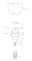
도 1은 본 발명의 실시 예1에 따른 치과용 임플란트 구조물을 나타낸 도면.
도 2는 도 1에 나타낸 어버트먼트의 단면을 나타낸 도면.
도 3은 도 1에 나타낸 크라운의 단면을 나타낸 도면.
도 4는 도 3에 나타낸 크라운을 어버트먼트에 결합하는 과정을 나타낸 단면도.
도 5는 본 발명의 다른 예로서, 외면에 탄성체가 형성된 어버트먼트의 단면을 나타낸 도면.
도 6은 도 5에 나타낸 크라운을 어버트먼트에 결합하는 과정을 나타낸 단면도.
도 7은 본 발명의 실시 예2에 따른 치과용 임플란트 구조물을 나타낸 도면.
도 8은 도 7에 나타낸 크라운의 단면을 나타낸 도면.
도 9는 도 7에 나타낸 크라운을 어버트먼트에 결합하는 과정을 나타낸 단면도.
도 10은 본 발명의 실시 예3에 따른 치과용 임플란트 구조물을 나타낸 도면.
도 11은 도 10에 나타낸 크라운의 단면을 나타낸 도면.
도 12는 도 11에 나타낸 크라운이 고정부재를 통해 어버트먼트에 결합된 상태를 나타낸 단면도. 1 is a view showing a dental implant structure according to Example 1 of the present invention.
Figure 2 is a view showing a cross section of the abutment shown in Figure 1;
Figure 3 is a view showing a cross section of the crown shown in Figure 1;
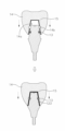
Figure 4 is a cross-sectional view showing a process of coupling the crown shown in Figure 3 to the abutment.
5 is another example of the present invention, a view showing a cross-section of an abutment in which an elastic body is formed on the outer surface.
Figure 6 is a cross-sectional view showing a process of coupling the crown shown in Figure 5 to the abutment.
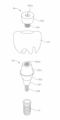
7 is a view showing a dental implant structure according to a second embodiment of the present invention.
Figure 8 is a view showing a cross section of the crown shown in Figure 7;
Figure 9 is a cross-sectional view showing a process of coupling the crown shown in Figure 7 to the abutment.
10 is a view showing a dental implant structure according to a third embodiment of the present invention.
11 is a view showing a cross section of the crown shown in FIG. 10;
Figure 12 is a cross-sectional view showing a state in which the crown shown in Figure 11 is coupled to the abutment through a fixing member.
이하, 본 발명의 이점 및 특징, 그것들을 달성하는 방법은 첨부되는 도면과 함께 상세하게 후술되는 실시 예들을 참조하면 명확해질 것이다. 또한, 본 명세서 전체에 걸쳐 동일 참조부호는 동일한 구성요소를 지칭하는 것이다. 또한, 각 도면에 도시된 각 구성요소들은 크기 및 형상이 과도하게 도시될 수도 있는데, 이는 설명의 편의를 위한 것으로 제한을 두고자 하는 것이 아니다. 또한, 'A 및/또는 B'라 기재된 경우 A와 B 모두를 의미하거나, 또는 A 또는 B 중 어느 하나를 의미할 수 있다. Hereinafter, the advantages and characteristics of the present invention, and methods for achieving them will become clear with reference to the embodiments to be described in detail in conjunction with the accompanying drawings. Also, like reference numerals designate like elements throughout this specification. In addition, each component shown in each figure may be excessively illustrated in size and shape, which is for convenience of description and is not intended to be limited. In addition, when described as 'A and/or B', it may mean both A and B, or either A or B.
본 발명에 따른 치과용 임플란트 구조물의 기술적 특징은 크게 ① 어버트먼트에 결합되는 크라운이 접착제를 사용하지 않고 걸림부를 통해 어버트먼트에 결합 고정된다. ② 어버트먼트와 크라운 사이에는 탄성체가 위치되어 이들 사이를 완충한다.The technical features of the dental implant structure according to the present invention are largely ① the crown coupled to the abutment is coupled and fixed to the abutment through the engaging portion without using an adhesive. ② An elastic material is placed between the abutment and the crown to cushion the gap between them.
상기 걸림부는 탄성링(실시 예1), 포스트의 상단부에 직경이 확장된 걸림돌부(실시 예2) 또는 숫나사부와 헤드부를 포함하는 고정부재(실시 예3) 중 어느 하나일 수 있다. The locking portion may be any one of an elastic ring (Embodiment 1), a locking protrusion having an expanded diameter at the upper end of the post (Embodiment 2), or a fixing member including a male screw portion and a head portion (Embodiment 3).
상기 탄성체는 어버트먼트의 외측면 또는 크라운의 내측면에 형성될 수도 있다. The elastic body may be formed on the outer surface of the abutment or the inner surface of the crown.
이러한 탄성체는 예를 들어 액상 상태의 탄성체 원료를 어버트먼트의 외면 또는 크라운의 수용공간의 내면에 도포한 후 경화시키는 방식(도포방식)으로 형성하거나, 기체 상태의 탄성체 원료를 어버트먼트의 외면 또는 크라운의 수용공간의 내면에 분사한 후 경화시키는 방식(분사방식)으로 형성할 수 있다. 또는 독립적으로 탄성체를 제조한 후 제조된 탄성체를 어버트먼트와 크라운 사이에 설치하는 방식으로 형성할 수 있다. Such an elastomer is formed, for example, by applying a liquid elastomer raw material to the outer surface of the abutment or to the inner surface of the receiving space of the crown and then curing it (application method), or by applying a gaseous elastomer raw material to the outer surface of the abutment. Alternatively, it may be formed by spraying on the inner surface of the receiving space of the crown and then curing (spraying). Alternatively, it may be formed by independently manufacturing an elastic body and then installing the manufactured elastic body between the abutment and the crown.
이하에서는, 본 발명에 따른 치과용 임플란트 구조물의 기술적 특징을 구현하기 위한 바람직한 예들을 첨부되는 도면들을 결부시켜 구체적으로 설명하기로 한다. Hereinafter, preferred examples for implementing the technical features of the dental implant structure according to the present invention will be described in detail in connection with the accompanying drawings.
도 1은 본 발명의 실시 예1에 따른 치과용 임플란트 구조물을 설명하기 위해 개략적으로 나타낸 도면으로서, 임플란트 구조물의 각 구성을 분리하여 나타낸 도면이다. 1 is a diagram schematically shown to explain a dental implant structure according to a first embodiment of the present invention, and is a view separately showing each component of the implant structure.
도 1을 참조하면, 본 발명의 실시 예1에 따른 치과용 임플란트 구조물은 크라운(14)과 어버트먼트(12) 간의 결합을 위해 탄성링(13)을 포함한다. 탄성링(13)은 크라운(14)을 어버트먼트(12)에 결합할 때 부드러운 결합특성을 제공하는 한편, 크라운(14)이 어버트먼트(12)에 결합된 후 쉽게 이탈되지 않도록 걸림(잠금) 역할을 수행한다.Referring to FIG. 1 , the dental implant structure according to the first embodiment of the present invention includes an
어버트먼트(12)는 예를 들어 고정부(121)와, 고정부(121)의 상부에 일체로 형성된 커프(122)와, 커프(122)의 상부에 일체로 형성된 포스트(123)를 포함할 수 있다. 이때, 고정부(121), 커프(122) 및 포스트(123)는 하나의 몸체로 이루어질 수 있다. The
이러한 어버트먼트(12)를 픽스쳐(11)에 고정하기 위해 고정부(121)의 하부에는 스크루(124)가 일체(원-피스(one-piece) 구조)로 형성될 수 있다. 또한, 스크루가 어버트먼트(12)와 개별적으로 분리된 투-피스(two-piece) 구조로 이루어질 수도 있다. 투-피스 구조의 경우, 스크루는 어버트먼트(12)의 중공을 통해 내부로 삽입될 수 있다. In order to fix the
커프(122)는 고정부(121)에서 상부로 갈수록 폭이 확장된 깔때기 구조로 이루어질 수 있다. 또한 포스트(123)와 커프(122)가 만나는 경계면에 단차가 발생되도록 하기 위해 포스트(123)는 커프(122)의 상면(122a) 보다 작은 직경(폭)을 갖도록 형성될 수 있고, 상부로 갈수록 폭이 동일하거나 감소하는 구조로 이루어질 수도 있다. The
도 2는 도 1에 나타낸 어버트먼트를 개략적으로 나타낸 단면도이다. 2 is a schematic cross-sectional view of the abutment shown in FIG. 1;
도 1 및 도 2와 같이, 포스트(123)는 둘레를 따라 링 형상으로 탄성링 삽입홈(123a)이 형성된다. 탄성링 삽입홈(123a)의 내부에는 도 1에 나타낸 탄성링(13)이 결합된다. 이때, 포스트(123) 내에서 탄성링 삽입홈(123a)은 1개 또는 2개 이상이 될 수 있다. 1 and 2, the
탄성링 삽입홈(123a)의 깊이는 탄성링(13)의 두께와 대응되도록 형성된다. 크라운(14)을 어버트먼트(12)의 포스트(123)에 씌울 때, 탄성링(13)이 크라운(14)의 내벽에 의해 수축하여 탄성링 삽입홈(123a)의 깊이방향으로 들어간다. 이때 크라운(14)의 진입을 방해하지 않는 깊이로 탄성링 삽입홈(123a)을 형성한다. 탄성링 삽입홈(123a)의 깊이는 탄성링(13)의 재질에 따라 달라질 수 있는데, 가령 탄성링(13)이 합성수지재(플라스틱재)나 금속재로 이루어진 경우에는 탄성링(13)의 두께보다 크게 형성할 수 있다. 예를 들어, 탄성링 삽입홈(123a)의 깊이는 탄성링(13)의 두께보다 0.1mm~0.5mm 깊게 형성할 수 있다. 링은 C형태로 만든다. 다른 예로, 탄성링(13)이 부피가 변할 수 있는 자체적인 탄성을 갖는 재질로 이루어진 경우에는 탄성링(13)이 탈락되지 않은 0-링 형태로 이루어질 수 있다. 이 경우 탄성링 삽입홈(123a)의 깊이는 O-링의 두께보다 0.1mm~0.5mm 얕게 형성할 수 있다. The depth of the elastic ring insertion groove (123a) is formed to correspond to the thickness of the elastic ring (13). When the
탄성링(13)의 직경은 탄성링(13)이 결합되는 포스트(123)의 수평 레벨에서 포스트(123)의 직경보다 작고, 링 형상으로 이루어진 탄성링 삽입홈(123a)의 직경과는 동일하거나 조금 작게 형성될 수 있다. 이에 따라 탄성링(13)을 탄성링 삽입홈(123a)에 결합하기 위해서는 탄성링(13)의 직경을 확장시켜 탄성링 삽입홈(123a)에 결합해야 하고, 탄성링 삽입홈(123a)에 결합된 후 탄성링(13)의 직경은 자체 탄성에 의해 축소된다. The diameter of the
탄성링(13)은 탄성을 갖는 탄성체일 수 있다. 예를 들어, 탄성링(13)을 부피 변화를 하지 않는 금속재나 합성수지재를 이용하여 제조할 경우에는 탄성으로 인한 길이 변화를 통해 그 효과를 얻고, 부피 변화를 하는 탄성체인 실리콘재, 불소고무와 같은 합성고무재 또는 탄성을 갖는 직물 형태의 금속재(예를 들면 Ni-Ti 합금으로 이루어진 얇은 니티놀 와이어(나이타이 와이어)를 직조한 직조물 또는 멤브레인) 또는 탄성을 갖는 합성수지재를 이용하여 제조할 경우에는 O-링 형태로 형성할 수 있다. The
도 1과 같이, 일례로 어버트먼트(12)가 원-피스 구조로 이루어진 경우, 포스트(123)의 상면에는 어버트먼트(12)를 픽스쳐(11)에 결합하기 위해 드라이버 홈(123b)이 형성될 수 있다. 예를 들어, 드라이버 홈(123b)은 일례로 헥사(육각형)로 이루어질 수 있다. 다른 예로, 어버트먼트(12)가 투-피스 구조로 이루어진 경우, 어버트먼트(12)의 내부에는 스크루가 삽입되기 위해 상하로 관통된 중공이 형성될 수 있다. 1, for example, when the
도 3은 도 1에 나타낸 크라운을 개략적으로 나타낸 단면도이고, 도 4는 도 3에 나타낸 크라운을 어버트먼트에 결합하는 과정을 개략적으로 나타낸 단면도이다.Figure 3 is a cross-sectional view schematically showing the crown shown in Figure 1, Figure 4 is a cross-sectional view schematically showing a process of coupling the crown shown in Figure 3 to the abutment.
도 3 및 도 4를 참조하면, 크라운(14)은 포스트(123)가 수용되는 수용공간(14a)이 형성되고, 수용공간(14a)에는 탄성링(13)이 삽입되어 걸림되는 걸림홈(14b)이 형성된다. 3 and 4, in the
걸림홈(14b)은 크라운(14)이 포스트(123)에 완전히 결합된 상태에서 탄성링 삽입홈(123a)과 상호 대응되도록 수용공간(14a)의 내면 둘레를 따라 도려내어 탄성링이 걸릴 수 있도록 형성한다.The locking
수용공간(14a)의 내면은 포스트(123)의 외면과 대응되는 형상으로 이루어질 수 있다. 이에 따라, 도 4와 같이, 포스트(123)가 크라운(14)의 수용공간(14a)에 삽입된 상태에서 포스트(123)는 크라운(14)의 수용공간(14a)에 긴밀하게 밀착 결합될 수 있다. The inner surface of the receiving
그리고, 도 3과 같이, 크라운(14)의 내면, 즉 수용공간(14a)의 내면에는 탄성체(15)가 형성될 수 있다. 이러한 탄성체(15)는 크라운(14)과 포스트(123)가 직접 맞닿는 것을 차단하는 역할을 수행한다. 크라운(14)과 포스트(123) 사이에 탄성체(15)가 존재하지 않는 경우에는 크라운(13)과 포스트(123)가 직접 맞닿는 부분이 존재하게 되고, 이는 탄성링(13)의 수축을 방해하는 요인이 된다. 즉, 크라운(14)과 포스트(123)가 직접 맞닿는 경우에는 크라운(14)과 포스트(123) 사이에 탄성링(13)이 수축할 수 있는 여유 공간이 마련되지 않기 때문에 탄성링(13)의 탄성력을 이용한 완충작용이 원활하게 작동하지 않는다. And, as shown in FIG. 3, an
탄성체(15)는 크라운(14)과 포스트(123) 사이에 형성되어 반복적으로 교합력이 가해질 때 이를 완충하여 크라운(14)과 어버트먼트(12) 간의 충돌에 의한 파절을 방지할 수 있다. 또한 크라운(14)이 포스트(123)에 결합될 때 일정 두께로 수축됨에 따라 크라운(14)과 포스트(123)의 틈새를 긴밀하게 메꾸어 준다. 이를 통해 크라운(14)과 포스트(123) 사이의 틈새로 이물질이 유입되는 것을 원천 차단할 수 있다. The
탄성체(15)는 탄성을 갖는 실리콘재나 고무재로 이루어질 수 있다. 이외에도 탄성링(13)으로 사용되는 재질을 포함하여 탄성을 갖는 재질은 모두 사용할 수 있다. 그리고, 탄성체(15)는 예를 들어 크라운(14)의 내면에 균일하게 형성하기 위해 코팅 공정을 통해 형성할 수 있다. 크라운(14)의 내면에 코팅 용액을 균일하게 분사하여 도포한 후, 도포된 코팅 용액을 경화시켜 일정한 두께로 균일하게 형성할 수 있다. The
상기 코팅 용액으로는 탄성력을 가지면서, 분무기나 분사노즐을 이용하여 분사방식으로 크라운(14)의 내면에 코팅이 가능한 재질을 사용할 수 있다. 예를 들어, 액체 상태의 합성수지재, 액체 상태의 합성고무재, 액체 상태의 실리콘재 또는 액체 상태의 실리콘 고무재 중 선택된 어느 하나를 사용할 수 있다. As the coating solution, a material that has elasticity and can be coated on the inner surface of the
예를 들어, 탄성체(15)는 분사 노즐을 이용하여 코팅 용액을 크라운(14)의 수용공간(14a) 내면에 분사하여 코팅한 후 경화시켜 형성할 수 있다. 이때, 탄성체(15)는 교합력에 의한 자연치아의 움직임이 평균적으로 30㎛인 점을 고려하여 20㎛~300㎛의 두께로 형성할 수 있다. For example, the
또한, 탄성체(15)는 탄성링(13)의 탄성력에 비해 큰 탄성력을 갖도록 형성될 수 있다. 탄성링(13)은 크라운(14)이 어버트먼트(12)에 결합된 상태에서 어버트먼트(12)로부터 쉽게 이탈되지 않도록 탄성체(15)에 비해 조금 단단한 재질로 형성될 수 있다. In addition, the
또한, 탄성체(15)는 부피 변화를 하는 탄성체인 실리콘재, 불소고무와 같은 합성고무재 또는 탄성을 갖는 직물 형태의 금속재(예를 들면 Ni-Ti 합금으로 이루어진 얇은 니티놀 와이어(나이타이 와이어)를 직조한 직조물 또는 멤브레인) 또는 탄성을 갖는 합성수지재로 이루어질 수 있다. 또한, 탄성체(15)는 합금 금속으로 이루어진 멤브레인 구조로 이루어진 경우 멤브레인의 빈 공간을 합성고무재나 실리콘 고무재가 채워진 구조로 이루어질 수도 있다. 또한 탄성체(15)는 불소고무와 같은 합성고무재, 실리콘을 주 원료로 하는 실리콘 고무재 또는 합성수지재로 이루어진 루어진 경우, 항생제, 항균제 또는 방향제들 중 적어도 어느 하나를 더 첨가할 수도 있다. In addition, the
도 4와 같이, 탄성링(13)이 포스트(123)의 탄성링 삽입홈(123a)에 결합된 상태에서 크라운(14)을 하강시켜 포스트(123)를 수용공간(14a)으로 진입시키면, 크라운(14)의 내벽(수용공간(14a)의 내벽)이 탄성링(13)을 가압한다. 탄성링(13)은 포스트(123)에 진입하는 크라운(14)의 내벽에 의해 눌려 수축되고, 크라운(14)의 걸림홈(14b)에 탄성링(13)의 일부가 삽입 결합되면, 크라운(14)에서 탄성링(13)으로 가해지는 가압력이 제거되어 탄성링(13)은 탄성 복원력에 의해 원상태로 복원되어 확장된다. 4, when the
크라운(14)이 포스트(123)의 외면을 덮도록 포스트(123)에 완전히 결합되면, 탄성링(13)은 크라운(14)에 형성된 걸림홈(14b)과 포스트(123)에 형성된 탄성링 삽입홈(123a) 사이에 삽입 결합된다. 따라서, 크라운(14)은 포스트(123)로부터 분리되는 방향으로 탄성링(13)에 의해 걸림되어 포스트(123)로부터 쉽게 분리되지 않는다.When the
탄성체(15)는 도 3과 같이 크라운(14)의 내면에 형성되어 있으나, 이는 일례로서, 도 5와 같이 크라운(14)의 내면과 접면하는 어버트먼트(12)의 포스트(123) 외면에 형성될 수도 있다. 그리고 탄성체(15)는 독립적으로 제작된 별도의 부재로서 어버트먼트(12)의 포스트(123)와 크라운(14) 사이에 단순히 삽입된 상태로 설치될 수도 있다. Although the
도 5는 본 발명의 다른 예로서, 외면에 탄성체가 형성된 어버트먼트를 개략적으로 나타낸 단면도이고, 도 6은 도 5에 나타낸 크라운을 어버트먼트에 결합하는 과정을 개략적으로 나타낸 단면도이다.5 is another example of the present invention, a cross-sectional view schematically showing an abutment having an elastic body formed on its outer surface, and FIG. 6 is a cross-sectional view schematically showing a process of coupling the crown shown in FIG. 5 to the abutment.
도 5 및 도 6과 같이, 탄성체(15)는 어버트먼트(12)의 포스트(123)의 외면에 형성된다. 이때 탄성체(15)는 탄성링 삽입홈(123a)의 내면을 포함하여 크라운(14)이 대면하는 포스트(123)의 측면, 그리고 드라이버 홀(123b)을 제외한 상면에도 형성될 수 있다. 이러한 탄성체(15)는 도 3에 나타낸 탄성체와 형성되는 위치만 다를 뿐 크라운(14)의 내면에 형성된 구조와 동일한 재질 및 동일한 작용 효과를 보일 수 있다. 5 and 6, the
도 7은 본 발명의 실시 예2에 따른 치과용 임플란트 구조물을 설명하기 위해 개략적으로 나타낸 도면으로서, 임플란트 구조물의 각 구성을 분리하여 나타낸 도면이다. 7 is a diagram schematically shown to explain a dental implant structure according to a second embodiment of the present invention, and is a view separately showing each component of the implant structure.
도 7을 참조하면, 본 발명의 실시 예2에 따른 치과용 임플란트 구조물은 어버트먼트(22)를 제외한 픽스쳐(21)와 크라운(23)은 실시 예1과 동일하게 형성될 수 있다. Referring to FIG. 7 , in the dental implant structure according to the second embodiment of the present invention, the
어버트먼트(22)는 가령 고정부(221), 커프(222), 포스트(223) 및 스크루(224)를 포함한다. 이들은 일체형 구조로 이루어지고, 기계 가공을 통해 형성될 수 있다. The
본 발명의 실시 예2에서, 포스트(223)는 실시 예1에 나타낸 포스트(123)와 다른 구조를 갖는다. 도 2와 같이, 본 발명의 실시 예1에 따른 포스트(123)에서는 크라운(14)이 접착제없이 탄성링(13)을 매개로 포스트(123)에 결합되는 구조로 이루어지는데 반해, 실시 예2에 따른 포스트(223)에서는 상단부에 형성된 걸림돌부(223a)를 매개로 크라운(23)의 내면에 형성된 걸림홈(23b)에 결합되는 구조로 이루어진다. In the second embodiment of the present invention, the
도 8은 도 7에 나타낸 크라운을 설명하기 위해 개략적으로 나타낸 단면도이다. 8 is a schematic cross-sectional view for explaining the crown shown in FIG. 7 .
도 7 및 도 8과 같이, 본 발명의 실시 예2에 따른 크라운(23)에서는 포스트(223)가 삽입되는 수용공간(23a)이 형성되고, 수용공간(23a)의 내측 상부에는 수평방향으로 확장되어 포스트(223)의 걸림돌부(223a)가 삽입된 후 상하방향, 즉 크라운(23)이 포스트(223)로부터 분리되는 방향으로 걸림되는 걸림홈(23b)이 형성되어 있다. 7 and 8, in the
또한, 크라운(23)(수용공간(23a))의 내면에는 탄성체(24)가 형성될 수 있다. 물론, 크라운(23) 대신에 포스트(223)의 외면에 형성될 수도 있다. 이때, 탄성체(24)는 본 발명의 실시 예1에 나타낸 탄성체(25)와 동일한 재질로 이루어질 수 있으며, 실시 예1에서와 같이 크라운(23)과 포스트(223) 사이에 설치되어 이들을 완충한다.In addition, an
그리고, 포스트(223)는 크라운(23)의 내벽에 밀착된 상태로 수용공간(23a)의 내부로 삽입될 때 수축될 수 있도록 슬릿(223b)에 의해 상단부가 서로 분할된 구조로 이루어질 수 있다. 이때, 슬릿(223b)의 개수와 형상은 제한을 두지 않는다. 예를 들어, 슬릿(223b)은 사선형, 헬리컬형(helical) 또는 회오리형으로 형성될 수 있다. In addition, the
슬릿(223b)은 도 7과 같이, 포스트(223)의 상부에서 상단부까지 연장 형성되고, 복수 개가 형성될 수 있다. 이에 따라 걸림돌부(223a)를 포함하여 포스트(223)의 상부는 슬릿(223b)을 경계로 슬릿(223b)의 갯수에 비례하여 복수 개로 분할 형성된다. As shown in FIG. 7 , the
도 9는 도 7에 나타낸 크라운을 어버트먼트에 결합하는 과정을 개략적으로 나타낸 단면도이다.9 is a cross-sectional view schematically illustrating a process of coupling the crown shown in FIG. 7 to the abutment.
도 9와 같이, 크라운(23)을 하강시키면, 포스트(223)가 수용공간(23a)으로 진입하면서 크라운(23)의 내벽(수용공간(23a)의 내벽)이 포스트(223)의 걸림돌부(223a)의 단부를 눌러 내측방향으로 가압한다. 걸림돌부(223a)는 슬릿(223b)에 의해 복수 개로 분할 형성됨에 따라 크라운(23)의 내벽에 의해 수축될 수 있고, 걸림돌부(223a)가 걸림홈(23b)으로 삽입 결합되면, 크라운(23)에서 걸림돌부(223a)로 가해지는 가압력이 제거되어 걸림돌부(223a)는 탄성 복원력에 의해 원상태로 복원되어 확장된다. 크라운(23)이 포스트(223)의 외면을 덮도록 포스트(223)에 완전히 결합되면, 걸림돌부(223a)는 크라운(23)에 형성된 걸림홈(23b)에 완전히 삽입 결합된다. 따라서, 크라운(23)은 포스트(223)로부터 분리되는 방향으로 걸림돌부(223a)와 걸림홈(23b)의 암수 결합을 통해 상호 걸림되어 포스트(223)로부터 쉽게 분리되지 않는다.As shown in FIG. 9, when the
도 10은 본 발명의 실시 예3에 따른 치과용 임플란트 구조물을 설명하기 위해 개략적으로 나타낸 도면으로서, 임플란트 구조물의 각 구성을 분리하여 나타낸 도면이다. 10 is a diagram schematically shown to explain a dental implant structure according to a third embodiment of the present invention, and is a view separately showing each component of the implant structure.
도 10을 참조하면, 본 발명의 실시 예3에 따른 치과용 임플란트 구조물은 크라운(34)을 어버트먼트(32)에 결합 고정하기 위한 고정부재(34)를 추가로 더 포함한다. Referring to FIG. 10 , the dental implant structure according to the third embodiment of the present invention further includes a fixing
어버트먼트(32)는 스크루(324)를 통해 픽스쳐(31)에 결합되는 고정부(321)와, 고정부(321)의 상부에 일체로 형성된 커프(322)와, 커프(322)의 상부에 형성된 포스트(323)를 포함한다. 포스트(323)은 상부 중앙에 형성되어 크라운(33)을 어버트먼트(32)에 결합 고정하는 고정부재(34)가 나사 결합되는 결합홈부(323a)를 포함한다. The
고정부재(34)는 포스트(323)의 결합홈부(323a)에 나사결합되는 숫나사부(341)가 형성되어 있고, 숫나사부(341)의 상부에는 크라운(33)의 내면에 하측방향으로 걸림되어 크라운(33)을 포스트(323)에 눌러 고정하는 헤드부(342)를 포함한다. The fixing
헤드부(342)는 크라운(33)의 내면에 걸림되도록 숫나사부(341)의 상단부 직경보다 크게 형성된다. 또한 헤드부(342)는 하단부에서 상단부로 갈수록 직경이 증가하는 구조로 이루어질 수 있다. 즉, 단면상에서 측면이 상향 경사진 구조로 이루어질 수 있다. 또한, 헤드부(342)의 상부에는 드라이버 공구를 이용하여 고정부재(34)를 회전시키기 위해 드라이버 공구가 삽입되는 드라이버 홈(342a)이 형성될 수 있다. 이때, 드라이버 홈(342a)은 일자형, 십자형 또는 헥사형 구조로 이루어질 수 있다. The
도 11은 도 10에 나타낸 크라운을 개략적으로 나타낸 단면도이고, 도 12는 도 11에 나타낸 크라운이 고정부재를 통해 어버트먼트에 결합된 상태를 나타낸 단면도이다. 11 is a cross-sectional view schematically showing the crown shown in FIG. 10, and FIG. 12 is a cross-sectional view showing a state in which the crown shown in FIG. 11 is coupled to the abutment through a fixing member.
도 10 내지 도 12와 같이, 크라운(33)의 내부에는 고정부재(34)가 내부로 인입되는 중공(33a)이 형성되어 있고, 중공(33a)과 상하로 연통하고 어버트먼트(32)의 포스트(323)가 삽입되어 수용되는 수용공간(33b)이 형성되어 있다. 이때, 수용공간(33b)의 내면 구조는 고정부재(34)의 헤드부(342)의 측면이 하측방향으로 걸림되도록 고정부재(34)의 외면 형상에 대응하는 구조로 이루어진다. 바람직하게, 고정부재(34)의 헤드부(342)의 측면이 하측방향(포스트(323)에 결합되는 방향)으로 걸림되도록 수용공간(33b)의 내면 중앙부의 내경이 좁아지는 구조로 이루어질 수 있다. As shown in FIGS. 10 to 12, a hollow 33a into which the fixing
또한, 크라운(33)의 수용공간(33b)의 내면에는 크라운(33)과 어버트먼트(32)의 포스트(323) 사이를 완충하기 위해 탄성체(35)가 부착 형성될 수 있다. 물론, 탄성체(35)는 크라운(33)의 수용공간(33b) 내면 대신에 어버트먼트(32)의 포스트(323)의 외면에 부착 형성될 수도 있다. 또한, 탄성체(35)는 독립적으로 제작된 후 상호 접면하는 크라운(33)과 어버트먼트(32)의 포스트(323) 사이에 설치될 수도 있다. In addition, an
한편, 고정부재(34)는 단면이 'T자형 구조로 이루어질 수도 있다. On the other hand, the fixing
본 발명의 실시 예들에 따른 치과용 임플란트 구조물들에서는 크라운이 어버트먼트에 접착제를 통해 고정되는 것이 아니라 걸림방식으로 어버트먼트에 결합 고정되고, 크라운과 어버트먼트 사이에 탄성체를 위치시켜 크라운에 가해지는 반복적인 교합력으로 인해 하부 구조물인 어버트먼트나 픽스쳐로 전달되는 압력이나 충격을 완화하며, 크라운과 어버트먼트 사이의 틈새로 이물질이 유입되는 것을 방지할 수 있다. In the dental implant structures according to the embodiments of the present invention, the crown is not fixed to the abutment through an adhesive, but coupled to the abutment in a hanging manner, and an elastic body is placed between the crown and the abutment to secure the crown. It is possible to relieve pressure or shock transmitted to an abutment or fixture, which is a lower structure, due to repetitive occlusal force applied, and to prevent foreign substances from being introduced into the gap between the crown and the abutment.
이상에서와 같이, 본 발명의 바람직한 실시 예가 특정 용어들을 사용하여 설명 및 도시되었지만, 그러한 용어는 오로지 본 발명을 명확하게 설명하기 위한 것일 뿐이다. 그리고, 본 발명의 실시 예 및 기술된 용어는 다음의 청구범위의 기술적 사상 및 범위로부터 이탈되지 않고서 여러 가지 변경 및 변화가 가해질 수 있는 것은 자명한 일이다. 이와 같이 변형된 실시 예들은 본 발명의 사상 및 범위로부터 개별적으로 이해되어져서는 안되며, 본 발명의 청구범위 안에 속한다고 해야 할 것이다.As above, although preferred embodiments of the present invention have been described and illustrated using specific terms, such terms are only intended to clearly describe the present invention. And, it is obvious that various changes and changes can be made to the embodiments of the present invention and the described terms without departing from the technical spirit and scope of the following claims. Such modified embodiments should not be individually understood from the spirit and scope of the present invention, and should be said to fall within the scope of the claims of the present invention.
11, 21, 31 : 픽스쳐 12, 22, 32 : 어버트먼트
13 : 탄성링 14, 23, 33 : 크라운
14a, 23a, 33b : 수용공간 14b, 23b : 걸림홈
15, 24 : 탄성체 33a : 중공
34 : 고정부재 121, 221 : 고정부
122, 222 : 커프 122a : 상면(커프)
123, 223, 323 : 포스트 123a : 탄성링 삽입홈
123b : 드라이버 홈 124, 224 : 스크루
223a : 걸림돌부 223b : 슬릿
232a : 결합홈부 341 : 숫나사부
342 : 헤드부 342a: 드라이버 홈11, 21, 31:
13:
14a, 23a, 33b:
15, 24:
34: fixing
122, 222:
123, 223, 323: post 123a: elastic ring insertion groove
123b:
223a:
232a: coupling groove 341: male screw
342:
Claims (10)
상기 어버트먼트의 포스트를 덮고, 걸림부를 통해 상기 포스트에 결합 고정되는 크라운; 및
상기 포스트와 상기 크라운 사이에 위치되는 탄성체; 를 포함하고,
상기 탄성체는 상기 포스트에 형성된 드라이버 홀을 제외한 상기 포스트의 외면에 코팅 형성된,
치과용 임플란트 구조물.
abutment;
a crown covering the post of the abutment and coupled and fixed to the post through a hooking part; and
an elastic body positioned between the post and the crown; including,
The elastic body is coated on the outer surface of the post except for the driver hole formed in the post,
Dental implant structure.
상기 걸림부는 상기 포스트의 외면에 띠 형상으로 형성된 탄성링 삽입홈에 삽입되는 탄성링으로 이루어지고, 상기 탄성링은 상기 포스트가 내부로 삽입되는 상기 크라운의 수용공간 내면에 형성된 걸림홈에 걸림되는 치과용 임플란트 구조물.
According to claim 1,
The locking portion is made of an elastic ring inserted into an elastic ring insertion groove formed in a band shape on an outer surface of the post, and the elastic ring is engaged in a locking groove formed on an inner surface of the receiving space of the crown into which the post is inserted. for implant structures.
상기 걸림부는 상기 포스트의 상단부에 직경이 확장된 걸림돌부로 이루어지고, 상기 걸림돌부는 상기 포스트가 내부로 삽입되는 상기 크라운의 수용공간 내면에 형성된 걸림홈에 걸림되는 치과용 임플란트 구조물.
According to claim 1,
The catching portion is made of a catching portion having an expanded diameter at an upper end of the post, and the catching portion is caught in a catching groove formed on an inner surface of the receiving space of the crown into which the post is inserted.
상기 걸림부는 상기 포스트에 형성된 결합홈부에 나사 결합되는 숫나사부와, 상기 숫나사부의 상단부에 형성되어 상기 포스트가 내부로 삽입되는 상기 크라운의 수용공간 내면에 걸림되는 헤드부를 포함하는 고정부재로 이루어진 치과용 임플란트 구조물.
According to claim 1,
The locking portion is composed of a fixing member including a male screw portion screwed into a coupling groove formed in the post and a head portion formed at an upper end of the male screw portion and hooked on an inner surface of the receiving space of the crown into which the post is inserted. implant structure.
상기 어버트먼트의 포스트를 덮고, 걸림부를 통해 상기 포스트에 결합 고정되는 크라운; 및
상기 포스트와 상기 크라운 사이에 위치되는 탄성체; 를 포함하고,
상기 탄성체는 상기 포스트가 수용되는 상기 크라운의 내면에 코팅 형성된,
치과용 임플란트 구조물.
abutment;
a crown covering the post of the abutment and coupled and fixed to the post through a hooking part; and
an elastic body positioned between the post and the crown; including,
The elastic body is coated on the inner surface of the crown in which the post is accommodated,
Dental implant structure.
상기 탄성체는 실리콘을 함유하는 실리콘 고무재, 불소를 함유한 합성고무재 또는 Ni-Ti 합금으로 이루어진 금속재 중 선택된 어느 하나로 이루어진 치과용 임플란트 구조물.
According to claim 1 or 5,
The elastic body is a dental implant structure made of any one selected from a metal material made of a silicone rubber material containing silicon, a synthetic rubber material containing fluorine, or a Ni-Ti alloy.
상기 탄성체는 Ni-Ti 합금 와이어를 이용하여 직물 또는 멤브레인 형태로 형성된 치과용 임플란트 구조물.
According to claim 1 or 5,
The elastic body is a dental implant structure formed in the form of a fabric or membrane using a Ni-Ti alloy wire.
상기 Ni-Ti 합금 와이어를 통해 형성된 멤브레인의 빈 공간에는 실리콘을 함유하는 실리콘 고무재 또는 불소를 함유한 합성고무재가 채워지는 치과용 임플란트 구조물.
According to claim 7,
A dental implant structure in which a silicone rubber material containing silicon or a synthetic rubber material containing fluorine is filled in the empty space of the membrane formed through the Ni-Ti alloy wire.
상기 탄성체는 항생제, 항균제 또는 방향제가 첨가된 치과용 임플란트 구조물.
According to claim 1 or 5,
The elastic body is a dental implant structure to which antibiotics, antibacterial agents or fragrances are added.
상기 탄성링은 O-링 또는 C-링의 형태로 이루어진 치과용 임플란트 구조물.According to claim 2,
The elastic ring is a dental implant structure made in the form of an O-ring or a C-ring.
Priority Applications (3)
| Application Number | Priority Date | Filing Date | Title |
|---|---|---|---|
| KR1020220129440A KR102527940B1 (en) | 2022-10-11 | 2022-10-11 | Implant structure for dental |
| PCT/KR2023/009198 WO2024080496A1 (en) | 2022-10-11 | 2023-06-30 | Dental implant structure |
| US18/280,664 US20250082443A1 (en) | 2022-10-11 | 2023-06-30 | Dental implant structure |
Applications Claiming Priority (1)
| Application Number | Priority Date | Filing Date | Title |
|---|---|---|---|
| KR1020220129440A KR102527940B1 (en) | 2022-10-11 | 2022-10-11 | Implant structure for dental |
Publications (1)
| Publication Number | Publication Date |
|---|---|
| KR102527940B1 true KR102527940B1 (en) | 2023-05-03 |
Family
ID=86380201
Family Applications (1)
| Application Number | Title | Priority Date | Filing Date |
|---|---|---|---|
| KR1020220129440A Active KR102527940B1 (en) | 2022-10-11 | 2022-10-11 | Implant structure for dental |
Country Status (3)
| Country | Link |
|---|---|
| US (1) | US20250082443A1 (en) |
| KR (1) | KR102527940B1 (en) |
| WO (1) | WO2024080496A1 (en) |
Cited By (5)
| Publication number | Priority date | Publication date | Assignee | Title |
|---|---|---|---|---|
| KR102625833B1 (en) | 2023-05-22 | 2024-01-16 | 이노덴 주식회사 | Dental implant system with function of prevent crown fracture |
| WO2024080496A1 (en) * | 2022-10-11 | 2024-04-18 | 이노덴 주식회사 | Dental implant structure |
| KR102658870B1 (en) | 2023-07-26 | 2024-04-19 | 이노덴 주식회사 | Dental abutment with a triple structure and dental implant system having the same |
| KR102793068B1 (en) * | 2023-11-23 | 2025-04-07 | 하명헌 | Implant structure |
| KR20250132778A (en) * | 2024-02-29 | 2025-09-05 | 이노덴 주식회사 | Cap for dental implants and dental implant system having the same |
Citations (7)
| Publication number | Priority date | Publication date | Assignee | Title |
|---|---|---|---|---|
| KR20080113949A (en) * | 2007-06-26 | 2008-12-31 | 이세준 | Implants and Prostheses for Implants |
| KR20090110136A (en) | 2008-04-17 | 2009-10-21 | 이도상 | Healing abutments of implant structures with healing covers |
| US20120264082A1 (en) * | 2009-06-10 | 2012-10-18 | Claude Segura | Device and method intended for holding a prosthesis in dental implantology |
| KR102038256B1 (en) * | 2019-07-18 | 2019-10-30 | 이재준 | Abutment for dental implant |
| KR102212709B1 (en) * | 2013-05-02 | 2021-02-05 | 주식회사 네오바이오텍 | Detachable dental implant |
| KR102323728B1 (en) | 2019-05-10 | 2021-11-09 | 주식회사 네오바이오텍 | Dental implant system |
| KR102427069B1 (en) * | 2021-08-04 | 2022-07-29 | 덴탈오케이 주식회사 | Implant crown fastening structure and fastening method |
Family Cites Families (7)
| Publication number | Priority date | Publication date | Assignee | Title |
|---|---|---|---|---|
| DE2733394C3 (en) * | 1977-07-23 | 1984-10-25 | Riess, Guido, Prof. Dr.med.dent., 8100 Garmisch-Partenkirchen | Artificial tooth with implantable tooth root |
| WO2005115270A1 (en) * | 2004-05-28 | 2005-12-08 | Brain Base Corporation | Prosthesis fixing structure and prosthesis fixing method |
| US7300282B2 (en) * | 2004-07-16 | 2007-11-27 | Sapian Schubert L | Biofunctional dental implant |
| AU2005286092B2 (en) * | 2004-09-23 | 2011-10-20 | L P M Dental Development Ltd. | Temporary dental prosthesis |
| US20200297463A1 (en) * | 2019-03-19 | 2020-09-24 | JET Dental, Inc. | Implantable abutments, abutment systems, and methods of operation thereof |
| CN113057751B (en) * | 2021-03-15 | 2022-02-08 | 周陈锋 | Bacteriostatic implanted tooth root and manufacturing method thereof |
| KR102527940B1 (en) * | 2022-10-11 | 2023-05-03 | 이노덴 주식회사 | Implant structure for dental |
-
2022
- 2022-10-11 KR KR1020220129440A patent/KR102527940B1/en active Active
-
2023
- 2023-06-30 US US18/280,664 patent/US20250082443A1/en active Pending
- 2023-06-30 WO PCT/KR2023/009198 patent/WO2024080496A1/en not_active Ceased
Patent Citations (7)
| Publication number | Priority date | Publication date | Assignee | Title |
|---|---|---|---|---|
| KR20080113949A (en) * | 2007-06-26 | 2008-12-31 | 이세준 | Implants and Prostheses for Implants |
| KR20090110136A (en) | 2008-04-17 | 2009-10-21 | 이도상 | Healing abutments of implant structures with healing covers |
| US20120264082A1 (en) * | 2009-06-10 | 2012-10-18 | Claude Segura | Device and method intended for holding a prosthesis in dental implantology |
| KR102212709B1 (en) * | 2013-05-02 | 2021-02-05 | 주식회사 네오바이오텍 | Detachable dental implant |
| KR102323728B1 (en) | 2019-05-10 | 2021-11-09 | 주식회사 네오바이오텍 | Dental implant system |
| KR102038256B1 (en) * | 2019-07-18 | 2019-10-30 | 이재준 | Abutment for dental implant |
| KR102427069B1 (en) * | 2021-08-04 | 2022-07-29 | 덴탈오케이 주식회사 | Implant crown fastening structure and fastening method |
Cited By (7)
| Publication number | Priority date | Publication date | Assignee | Title |
|---|---|---|---|---|
| WO2024080496A1 (en) * | 2022-10-11 | 2024-04-18 | 이노덴 주식회사 | Dental implant structure |
| KR102625833B1 (en) | 2023-05-22 | 2024-01-16 | 이노덴 주식회사 | Dental implant system with function of prevent crown fracture |
| KR102658870B1 (en) | 2023-07-26 | 2024-04-19 | 이노덴 주식회사 | Dental abutment with a triple structure and dental implant system having the same |
| WO2025023811A1 (en) * | 2023-07-26 | 2025-01-30 | 이노덴 주식회사 | Dental abutment having triple structure and dental implant system including same |
| KR102793068B1 (en) * | 2023-11-23 | 2025-04-07 | 하명헌 | Implant structure |
| KR20250132778A (en) * | 2024-02-29 | 2025-09-05 | 이노덴 주식회사 | Cap for dental implants and dental implant system having the same |
| KR102884777B1 (en) * | 2024-02-29 | 2025-11-11 | 이노덴 주식회사 | Cap for dental implants and dental implant system having the same |
Also Published As
| Publication number | Publication date |
|---|---|
| WO2024080496A1 (en) | 2024-04-18 |
| US20250082443A1 (en) | 2025-03-13 |
Similar Documents
| Publication | Publication Date | Title |
|---|---|---|
| KR102527940B1 (en) | Implant structure for dental | |
| EP0510115B1 (en) | Abutment for dental appliances and the like | |
| US5362234A (en) | Self-drilling endosteal hollow-basket implant system with shock-absorber | |
| US4540367A (en) | Dental attachment structure | |
| US5052931A (en) | Enossal implant | |
| CA2609100C (en) | Improvements in components for permanent removable and adjustable dentures and bridges | |
| US20060141418A1 (en) | Method for treating a screw-cement retained prosthesis, abutment and implant for a screw-cement retained prosthesis | |
| KR102480663B1 (en) | Method for manufacturing implant structure with a crown moving in response to bite force and the implant structure manufactured using the same | |
| US3618212A (en) | Dental prosthetic construction | |
| KR102304199B1 (en) | Non-adhesive thumbtack-shaped abutment and implant having the same | |
| KR101419519B1 (en) | Implant assembly | |
| SE465701B (en) | DEVICE FOR DENTAL IMPLANT INCLUDING A LOWER SCREW | |
| KR20170038004A (en) | Fixed hybrid dental attachment assembly and methods of use | |
| KR101608176B1 (en) | Implant unit | |
| KR101660183B1 (en) | Implant unit | |
| KR102568818B1 (en) | Connector and dental implant system having the same | |
| US8926326B2 (en) | Denture retention system | |
| KR102362852B1 (en) | Abutment for implant with cap that strengthens bonding with artificial teeth | |
| JPH05168651A (en) | Artificial tooth root | |
| KR102247632B1 (en) | A Dental implants with excellent biocompatibility | |
| KR102658870B1 (en) | Dental abutment with a triple structure and dental implant system having the same | |
| JPH078508A (en) | Artificial tooth root | |
| KR102165212B1 (en) | Dental implant | |
| KR20190060776A (en) | Caps for mounting on stationary elements | |
| KR102048659B1 (en) | Improved implant assembly with screw loosening prevention fucntion |
Legal Events
| Date | Code | Title | Description |
|---|---|---|---|
| PA0109 | Patent application |
St.27 status event code: A-0-1-A10-A12-nap-PA0109 |
|
| PA0201 | Request for examination |
St.27 status event code: A-1-2-D10-D11-exm-PA0201 |
|
| PA0302 | Request for accelerated examination |
St.27 status event code: A-1-2-D10-D17-exm-PA0302 St.27 status event code: A-1-2-D10-D16-exm-PA0302 |
|
| D13-X000 | Search requested |
St.27 status event code: A-1-2-D10-D13-srh-X000 |
|
| D14-X000 | Search report completed |
St.27 status event code: A-1-2-D10-D14-srh-X000 |
|
| PE0902 | Notice of grounds for rejection |
St.27 status event code: A-1-2-D10-D21-exm-PE0902 |
|
| P11-X000 | Amendment of application requested |
St.27 status event code: A-2-2-P10-P11-nap-X000 |
|
| P13-X000 | Application amended |
St.27 status event code: A-2-2-P10-P13-nap-X000 |
|
| E701 | Decision to grant or registration of patent right | ||
| PE0701 | Decision of registration |
St.27 status event code: A-1-2-D10-D22-exm-PE0701 |
|
| GRNT | Written decision to grant | ||
| PR0701 | Registration of establishment |
St.27 status event code: A-2-4-F10-F11-exm-PR0701 |
|
| PR1002 | Payment of registration fee |
St.27 status event code: A-2-2-U10-U11-oth-PR1002 Fee payment year number: 1 |
|
| PG1601 | Publication of registration |
St.27 status event code: A-4-4-Q10-Q13-nap-PG1601 |
|
| PR1001 | Payment of annual fee |
St.27 status event code: A-4-4-U10-U11-oth-PR1001 Fee payment year number: 4 |
|
| U11 | Full renewal or maintenance fee paid |
Free format text: ST27 STATUS EVENT CODE: A-4-4-U10-U11-OTH-PR1001 (AS PROVIDED BY THE NATIONAL OFFICE) Year of fee payment: 4 |