KR102519666B1 - Device and method to convert image - Google Patents
Device and method to convert image Download PDFInfo
- Publication number
- KR102519666B1 KR102519666B1 KR1020180122245A KR20180122245A KR102519666B1 KR 102519666 B1 KR102519666 B1 KR 102519666B1 KR 1020180122245 A KR1020180122245 A KR 1020180122245A KR 20180122245 A KR20180122245 A KR 20180122245A KR 102519666 B1 KR102519666 B1 KR 102519666B1
- Authority
- KR
- South Korea
- Prior art keywords
- image
- point
- input image
- image conversion
- conversion device
- Prior art date
- Legal status (The legal status is an assumption and is not a legal conclusion. Google has not performed a legal analysis and makes no representation as to the accuracy of the status listed.)
- Active
Links
Images


Classifications
-
- G—PHYSICS
- G06—COMPUTING OR CALCULATING; COUNTING
- G06T—IMAGE DATA PROCESSING OR GENERATION, IN GENERAL
- G06T7/00—Image analysis
- G06T7/50—Depth or shape recovery
- G06T7/536—Depth or shape recovery from perspective effects, e.g. by using vanishing points
-
- G06T3/0093—
-
- G—PHYSICS
- G06—COMPUTING OR CALCULATING; COUNTING
- G06T—IMAGE DATA PROCESSING OR GENERATION, IN GENERAL
- G06T3/00—Geometric image transformations in the plane of the image
- G06T3/18—Image warping, e.g. rearranging pixels individually
-
- G—PHYSICS
- G06—COMPUTING OR CALCULATING; COUNTING
- G06V—IMAGE OR VIDEO RECOGNITION OR UNDERSTANDING
- G06V20/00—Scenes; Scene-specific elements
- G06V20/50—Context or environment of the image
- G06V20/56—Context or environment of the image exterior to a vehicle by using sensors mounted on the vehicle
-
- G—PHYSICS
- G06—COMPUTING OR CALCULATING; COUNTING
- G06T—IMAGE DATA PROCESSING OR GENERATION, IN GENERAL
- G06T17/00—Three-dimensional [3D] modelling for computer graphics
- G06T17/05—Geographic models
-
- G—PHYSICS
- G06—COMPUTING OR CALCULATING; COUNTING
- G06T—IMAGE DATA PROCESSING OR GENERATION, IN GENERAL
- G06T7/00—Image analysis
- G06T7/10—Segmentation; Edge detection
- G06T7/11—Region-based segmentation
-
- G—PHYSICS
- G06—COMPUTING OR CALCULATING; COUNTING
- G06T—IMAGE DATA PROCESSING OR GENERATION, IN GENERAL
- G06T7/00—Image analysis
- G06T7/10—Segmentation; Edge detection
- G06T7/12—Edge-based segmentation
-
- G—PHYSICS
- G06—COMPUTING OR CALCULATING; COUNTING
- G06T—IMAGE DATA PROCESSING OR GENERATION, IN GENERAL
- G06T7/00—Image analysis
- G06T7/10—Segmentation; Edge detection
- G06T7/136—Segmentation; Edge detection involving thresholding
-
- G—PHYSICS
- G06—COMPUTING OR CALCULATING; COUNTING
- G06T—IMAGE DATA PROCESSING OR GENERATION, IN GENERAL
- G06T7/00—Image analysis
- G06T7/97—Determining parameters from multiple pictures
-
- G—PHYSICS
- G06—COMPUTING OR CALCULATING; COUNTING
- G06V—IMAGE OR VIDEO RECOGNITION OR UNDERSTANDING
- G06V10/00—Arrangements for image or video recognition or understanding
- G06V10/20—Image preprocessing
- G06V10/26—Segmentation of patterns in the image field; Cutting or merging of image elements to establish the pattern region, e.g. clustering-based techniques; Detection of occlusion
- G06V10/267—Segmentation of patterns in the image field; Cutting or merging of image elements to establish the pattern region, e.g. clustering-based techniques; Detection of occlusion by performing operations on regions, e.g. growing, shrinking or watersheds
-
- G—PHYSICS
- G06—COMPUTING OR CALCULATING; COUNTING
- G06V—IMAGE OR VIDEO RECOGNITION OR UNDERSTANDING
- G06V10/00—Arrangements for image or video recognition or understanding
- G06V10/40—Extraction of image or video features
- G06V10/44—Local feature extraction by analysis of parts of the pattern, e.g. by detecting edges, contours, loops, corners, strokes or intersections; Connectivity analysis, e.g. of connected components
-
- G—PHYSICS
- G06—COMPUTING OR CALCULATING; COUNTING
- G06V—IMAGE OR VIDEO RECOGNITION OR UNDERSTANDING
- G06V20/00—Scenes; Scene-specific elements
- G06V20/50—Context or environment of the image
- G06V20/56—Context or environment of the image exterior to a vehicle by using sensors mounted on the vehicle
- G06V20/58—Recognition of moving objects or obstacles, e.g. vehicles or pedestrians; Recognition of traffic objects, e.g. traffic signs, traffic lights or roads
-
- G—PHYSICS
- G06—COMPUTING OR CALCULATING; COUNTING
- G06V—IMAGE OR VIDEO RECOGNITION OR UNDERSTANDING
- G06V20/00—Scenes; Scene-specific elements
- G06V20/50—Context or environment of the image
- G06V20/56—Context or environment of the image exterior to a vehicle by using sensors mounted on the vehicle
- G06V20/588—Recognition of the road, e.g. of lane markings; Recognition of the vehicle driving pattern in relation to the road
-
- G—PHYSICS
- G06—COMPUTING OR CALCULATING; COUNTING
- G06V—IMAGE OR VIDEO RECOGNITION OR UNDERSTANDING
- G06V20/00—Scenes; Scene-specific elements
- G06V20/60—Type of objects
- G06V20/64—Three-dimensional [3D] objects
- G06V20/647—Three-dimensional [3D] objects by matching two-dimensional images to three-dimensional objects
-
- G—PHYSICS
- G08—SIGNALLING
- G08G—TRAFFIC CONTROL SYSTEMS
- G08G1/00—Traffic control systems for road vehicles
- G08G1/16—Anti-collision systems
- G08G1/167—Driving aids for lane monitoring, lane changing, e.g. blind spot detection
-
- G—PHYSICS
- G06—COMPUTING OR CALCULATING; COUNTING
- G06T—IMAGE DATA PROCESSING OR GENERATION, IN GENERAL
- G06T2207/00—Indexing scheme for image analysis or image enhancement
- G06T2207/30—Subject of image; Context of image processing
- G06T2207/30248—Vehicle exterior or interior
- G06T2207/30252—Vehicle exterior; Vicinity of vehicle
- G06T2207/30256—Lane; Road marking
-
- G—PHYSICS
- G06—COMPUTING OR CALCULATING; COUNTING
- G06T—IMAGE DATA PROCESSING OR GENERATION, IN GENERAL
- G06T2207/00—Indexing scheme for image analysis or image enhancement
- G06T2207/30—Subject of image; Context of image processing
- G06T2207/30248—Vehicle exterior or interior
- G06T2207/30252—Vehicle exterior; Vicinity of vehicle
- G06T2207/30261—Obstacle
Landscapes
- Engineering & Computer Science (AREA)
- Physics & Mathematics (AREA)
- General Physics & Mathematics (AREA)
- Theoretical Computer Science (AREA)
- Computer Vision & Pattern Recognition (AREA)
- Multimedia (AREA)
- Geometry (AREA)
- Software Systems (AREA)
- Remote Sensing (AREA)
- Computer Graphics (AREA)
- Image Analysis (AREA)
- Image Processing (AREA)
Abstract
이미지 변환 장치 및 방법이 제공된다. 이미지 변환 장치는 입력 이미지에 나타난 차로 경계선의 변곡점에 기초하여 입력 이미지를 복수의 영역 이미지들로 분할하고, 각 영역 이미지마다 소실점 및 변환 관계를 계산하며, 계산된 변환 관계에 기초하여 전체 입력 이미지에 대한 도로 프로파일 데이터를 생성할 수 있다.An image conversion device and method are provided. The image conversion device divides the input image into a plurality of area images based on the inflection point of the lane boundary appearing in the input image, calculates a vanishing point and a transformation relationship for each area image, and converts the entire input image based on the calculated transformation relationship. It is possible to generate road profile data for
Description
이하, 이미지를 변환하는 기술이 제공된다.Hereinafter, a technique for converting an image is provided.
자율주행(예를 들어, ADAS(Advanced Driver Assistance System) 등) 에서는 ACC(Active Cruise Control) 기술이 필수적이다. ACC 기술은 현재 차량이 주행하고 있는 차로 내에서 선행하는 차량의 속도를 센싱하고, 차량이 선행하는 차량과 일정거리를 유지하며 주행함으로써 충돌하지 않도록, 차량의 속도를 조절하는 기술이다.In autonomous driving (eg, Advanced Driver Assistance System (ADAS), etc.), Active Cruise Control (ACC) technology is essential. The ACC technology is a technology that senses the speed of a preceding vehicle within the lane in which the vehicle is currently driving and adjusts the speed of the vehicle so that the vehicle does not collide by driving while maintaining a certain distance from the preceding vehicle.
현재 출시되고 있는 차량들 중 일부는 원하는 타겟 속도를 입력하면, 선행하는 차량이 없는 경우 타겟 속도로 주행하고, 선행하는 차량이 나타나면 그에 맞추어 속도를 줄여서 일정 거리를 유지하는 기능을 포함하고 있다. 이러한 기술 구현을 위해서는 주변 객체의 위치를 정확하게 추정할 필요가 있다.Some of the vehicles currently on the market include a function of inputting a desired target speed, driving at the target speed when there is no preceding vehicle, and reducing speed accordingly to maintain a certain distance when a preceding vehicle appears. To implement this technology, it is necessary to accurately estimate the location of surrounding objects.
일 실시예에 따르면 이미지 변환 방법은 전방 도로에 대한 입력 이미지를 복수의 영역 이미지(region image)들로 분할(segment)하는 단계; 상기 분할된 영역 이미지들 중 각 영역 이미지에 대해 소실점(vanishing point)을 결정하는 단계; 상기 소실점에 기초하여 각 영역 이미지의 2차원 좌표를 3차원 좌표로 변환하는 변환 관계(translation relation)를 계산하는 단계; 및 각 영역 이미지마다 계산된 상기 변환 관계에 기초하여, 상기 분할된 영역 이미지들로부터 도로 프로파일 데이터(road profile data)를 생성하는 단계를 포함할 수 있다.According to an embodiment, an image conversion method includes segmenting an input image of a road ahead into a plurality of region images; determining a vanishing point for each region image among the divided region images; calculating a translation relation for converting 2D coordinates of each region image into 3D coordinates based on the vanishing point; and generating road profile data from the divided region images based on the transformation relationship calculated for each region image.
상기 입력 이미지를 복수의 영역 이미지들로 분할하는 단계는, 상기 입력 이미지로부터 차로 경계선을 식별하는 단계; 상기 식별된 차로 경계선의 변곡점(inflection point)을 계산하는 단계; 및 상기 계산된 변곡점을 기준으로 상기 입력 이미지를 복수의 영역 이미지들로 분할하는 단계를 포함할 수 있다.The dividing of the input image into a plurality of area images may include identifying a boundary line of a vehicle from the input image; calculating an inflection point of the identified lane boundary line; and dividing the input image into a plurality of region images based on the calculated inflection point.
상기 변곡점을 계산하는 단계는, 상기 식별된 차로 경계선을 복수의 구간들(sections)로 분할하는 단계; 상기 복수의 구간들의 각각에 나타난 일부 경계선(partial line)의 기울기(slope)를 산출하는 단계; 및 상기 일부 경계선의 기울기에 기초하여, 상기 변곡점을 계산하는 단계를 포함할 수 있다.The calculating of the inflection point may include dividing the identified lane boundary into a plurality of sections; Calculating a slope of a partial line appearing in each of the plurality of sections; and calculating the inflection point based on the slope of the partial boundary line.
상기 변곡점을 계산하는 단계는, 일부 경계선들 중 인접한 두 일부 경계선 간의 기울기 차이(slope difference)가 임계 차이(threshold difference)를 초과하는 경우에 응답하여, 상기 인접한 두 일부 경계선 사이의 지점을 상기 변곡점으로 결정하는 단계를 포함할 수 있다.In the step of calculating the inflection point, in response to a case where a slope difference between two adjacent partial boundary lines among some boundary lines exceeds a threshold difference, a point between the two adjacent partial boundary lines is set as the inflection point. It may include a decision-making step.
상기 계산된 변곡점을 기준으로 상기 입력 이미지를 복수의 영역 이미지들로 분할하는 단계는, 상기 입력 이미지에서 상기 변곡점을 포함하는 수평선을 기준으로 상기 입력 이미지를 분할하는 단계를 포함할 수 있다.Dividing the input image into a plurality of region images based on the calculated inflection point may include dividing the input image based on a horizontal line including the inflection point in the input image.
상기 변곡점을 계산하는 단계는, 상기 입력 이미지에서 복수의 차로 경계선들이 검출된 경우에 응답하여, 상기 복수의 차로 경계선들 중 상기 입력 이미지의 중심에 가장 가까운 차로 경계선을 선택하는 단계; 및 상기 선택된 차로 경계선의 변곡점을 계산하는 단계를 포함할 수 있다.The calculating of the inflection point may include: selecting a lane boundary line closest to a center of the input image from among the plurality of lane boundary lines in response to detection of a plurality of lane boundary lines in the input image; and calculating an inflection point of the boundary line of the selected lane.
상기 분할된 영역 이미지들 중 각 영역 이미지에 대해 소실점을 결정하는 단계는, 각 영역 이미지에 나타난 차로 경계선들을 연장하는 단계; 및 상기 연장된 차로 경계선들이 서로 교차하는 지점을 해당 영역 이미지에 대한 소실점으로 결정하는 단계를 포함할 수 있다.Determining a vanishing point for each area image among the divided area images may include extending boundary lines of a road appearing in each area image; and determining a point where the extended lane boundary lines intersect with each other as a vanishing point for the corresponding area image.
상기 연장된 차로 경계선들이 서로 교차하는 지점을 해당 영역 이미지에 대한 소실점으로 결정하는 단계는, 상기 연장된 차로 경계선들이 복수의 지점들에서 교차하는 경우에 응답하여, 상기 복수의 지점들에 기초하여 단일 지점을 상기 소실점으로 결정하는 단계를 포함할 수 있다.Determining a point at which the extended lane boundary lines intersect each other as a vanishing point for the corresponding area image may include, in response to a case where the extended lane boundary lines intersect at a plurality of points, a single point based on the plurality of points. A step of determining a point as the vanishing point may be included.
상기 변환 관계를 계산하는 단계는, 상기 분할된 영역 이미지들에 대해, 이미지 센서의 시야각의 중심축에 평행한 평면을 기준으로 하는 경사도(inclination level)를 상기 소실점에 기초하여 산출하는 단계를 포함할 수 있다.The calculating of the conversion relation may include calculating an inclination level based on a plane parallel to a central axis of a viewing angle of an image sensor for the divided area images based on the vanishing point. can
상기 도로 프로파일 데이터를 생성하는 단계는, 상기 입력 이미지의 각 지점들의 물리 위치(physical location)에 대한 좌표를 포함하는 상기 도로 프로파일 데이터를 생성하는 단계를 포함할 수 있다.The generating of the road profile data may include generating the road profile data including coordinates of physical locations of respective points of the input image.
일 실시예에 따른 이미지 변환 장치는 전방 도로에 대한 입력 이미지를 획득하는 이미지 획득부; 및 상기 입력 이미지를 복수의 영역 이미지(region image)들로 분할하고, 상기 분할된 영역 이미지들 중 각 영역 이미지에 대해 소실점을 결정하며, 상기 소실점에 기초하여 각 영역 이미지의 2차원 좌표를 3차원 좌표로 변환하는 변환 관계를 계산하고, 각 영역 이미지마다 계산된 상기 변환 관계에 기초하여, 상기 분할된 영역 이미지들로부터 도로 프로파일 데이터를 생성하는 프로세서를 포함할 수 있다.An image conversion device according to an embodiment includes an image acquisition unit acquiring an input image of a road ahead; and dividing the input image into a plurality of region images, determining a vanishing point for each region image among the divided region images, and converting 2D coordinates of each region image into 3D coordinates based on the vanishing point. and a processor that calculates a transformation relationship for transforming into coordinates and generates road profile data from the divided area images based on the transformation relationship calculated for each area image.
도 1은 일 실시예에 따른 이미지 변환을 설명하는 도면이다.
도 2는 일 실시예에 따른 이미지 변환 방법을 설명하는 흐름도이다.
도 3은 일 실시예에 따른 이미지 분할을 설명하는 흐름도이다.
도 4는 일 실시예에 따른 영역 이미지의 예시를 설명하는 도면이다.
도 5는 일 실시예에 따라 산출된 변곡점에 기초한 영역 분할을 설명하는 도면이다.
도 6은 일 실시예에 따른 변곡점 검출을 설명하는 도면이다.
도 7은 일 실시예에 따른 소실점의 결정을 설명하는 흐름도이다.
도 8은 일 실시예에 따른 영역 이미지들 별 소실점을 설명하는 도면이다.
도 9는 일 실시예에 따른 변환 관계의 계산 및 도로 프로파일 데이터의 생성을 설명하는 도면이다.
도 10은 일 실시예에 따른 이미지 변환 장치의 구성을 설명하는 블록도이다.1 is a diagram illustrating image conversion according to an exemplary embodiment.
2 is a flowchart illustrating an image conversion method according to an exemplary embodiment.
3 is a flowchart illustrating image segmentation according to an exemplary embodiment.
4 is a diagram illustrating an example of a region image according to an exemplary embodiment.
5 is a diagram explaining region division based on the calculated inflection point according to an exemplary embodiment.
6 is a diagram illustrating detection of an inflection point according to an exemplary embodiment.
7 is a flowchart illustrating the determination of a vanishing point according to an exemplary embodiment.
8 is a diagram illustrating a vanishing point for each area image according to an exemplary embodiment.
9 is a diagram illustrating calculation of a conversion relationship and generation of road profile data according to an exemplary embodiment.
10 is a block diagram illustrating the configuration of an image conversion device according to an exemplary embodiment.
이하, 실시예들을 첨부된 도면을 참조하여 상세하게 설명한다. 그러나, 특허출원의 범위가 이러한 실시예들에 의해 제한되거나 한정되는 것은 아니다. 각 도면에 제시된 동일한 참조 부호는 동일한 부재를 나타낸다.Hereinafter, embodiments will be described in detail with reference to the accompanying drawings. However, the scope of the patent application is not limited or limited by these examples. Like reference numerals in each figure indicate like elements.
아래 설명하는 실시예들에는 다양한 변경이 가해질 수 있다. 아래 설명하는 실시예들은 실시 형태에 대해 한정하려는 것이 아니며, 이들에 대한 모든 변경, 균등물 내지 대체물을 포함하는 것으로 이해되어야 한다.Various changes may be made to the embodiments described below. The embodiments described below are not intended to be limiting on the embodiments, and should be understood to include all modifications, equivalents or substitutes thereto.
실시예에서 사용한 용어는 단지 특정한 실시예를 설명하기 위해 사용된 것으로, 실시예를 한정하려는 의도가 아니다. 단수의 표현은 문맥상 명백하게 다르게 뜻하지 않는 한, 복수 개의 표현을 포함한다. 본 명세서에서, "포함하다" 또는 "가지다" 등의 용어는 명세서 상에 기재된 특징, 숫자, 단계, 동작, 구성 요소, 부품 또는 이들을 조합한 것이 존재함을 지정하려는 것이지, 하나 또는 그 이상의 다른 특징들이나 숫자, 단계, 동작, 구성요소, 부품 또는 이들을 조합한 것들의 존재 또는 부가 가능성을 미리 배제하지 않는 것으로 이해되어야 한다.Terms used in the examples are used only to describe specific examples, and are not intended to limit the examples. Expressions in the singular number include plural expressions unless the context clearly dictates otherwise. In this specification, terms such as "include" or "have" are intended to designate that there is a feature, number, step, operation, component, part, or combination thereof described in the specification, but one or more other features It should be understood that the presence or addition of numbers, steps, operations, components, parts, or combinations thereof is not precluded.
다르게 정의되지 않는 한, 기술적이거나 과학적인 용어를 포함해서 여기서 사용되는 모든 용어들은 실시예가 속하는 기술 분야에서 통상의 지식을 가진 자에 의해 일반적으로 이해되는 것과 동일한 의미를 가지고 있다. 일반적으로 사용되는 사전에 정의되어 있는 것과 같은 용어들은 관련 기술의 문맥 상 가지는 의미와 일치하는 의미를 가지는 것으로 해석되어야 하며, 본 출원에서 명백하게 정의하지 않는 한, 이상적이거나 과도하게 형식적인 의미로 해석되지 않는다.Unless defined otherwise, all terms used herein, including technical or scientific terms, have the same meaning as commonly understood by a person of ordinary skill in the art to which the embodiment belongs. Terms such as those defined in commonly used dictionaries should be interpreted as having a meaning consistent with the meaning in the context of the related art, and unless explicitly defined in the present application, they should not be interpreted in an ideal or excessively formal meaning. don't
또한, 첨부 도면을 참조하여 설명함에 있어, 도면 부호에 관계없이 동일한 구성 요소는 동일한 참조 부호를 부여하고 이에 대한 중복되는 설명은 생략하기로 한다. 실시예를 설명함에 있어서 관련된 공지 기술에 대한 구체적인 설명이 실시예의 요지를 불필요하게 흐릴 수 있다고 판단되는 경우 그 상세한 설명을 생략한다.In addition, in the description with reference to the accompanying drawings, the same reference numerals are given to the same components regardless of reference numerals, and overlapping descriptions thereof will be omitted. In describing the embodiment, if it is determined that a detailed description of a related known technology may unnecessarily obscure the gist of the embodiment, the detailed description will be omitted.
도 1은 일 실시예에 따른 이미지 변환을 설명하는 도면이다.1 is a diagram illustrating image conversion according to an exemplary embodiment.
일 실시예에 따르면, 이미지 변환 장치는 제1 뷰(first view)에서 획득된 입력 이미지(110)를 제2 뷰(second view)의 출력 이미지(120)로 변환할 수 있다. 예를 들어, 도 1에서 제1 뷰는 투시 뷰(perspective view)일 수 있고, 제2 뷰는 탑뷰(top view)일 수 있다. 이미지 변환 장치는 제1 뷰의 입력 이미지(110)를 제2 뷰의 출력 이미지(120)로 변환하기 위한 변환 관계(translation relation)를 계산할 수 있다.According to one embodiment, the image conversion device may convert the
예를 들어, 자율주행 시스템에서 주행을 하기 위한 기본적인 동작들은, 차로(lane)를 검출하는 동작, 차로의 중앙에서 주행을 유지하는 동작, 및 선행 차량과의 거리를 유지하는 동작을 포함할 수 있다. 카메라 기반의 자율주행 시스템에서 상술한 동작들이 모노큘러 카메라(monocular camera)에 의해 획득된 이미지에 기초하여 수행될 수 있다. 자율주행 차량은 모노큘러 카메라를 통해 획득된 이미지에 기초하여 주변의 객체 또는 배경(예를 들어, 도로)까지의 위치 관계를 알아냄(finding)으로써, 상술한 동작들을 수행할 수 있다.For example, basic operations for driving in an autonomous driving system may include an operation of detecting a lane, an operation of maintaining driving in the center of the lane, and an operation of maintaining a distance from a preceding vehicle. . In the camera-based autonomous driving system, the above-described operations may be performed based on an image acquired by a monocular camera. The self-driving vehicle may perform the above-described operations by finding a positional relationship to a surrounding object or background (eg, a road) based on an image acquired through a monocular camera.
일 실시예에 따른 이미지 변환 장치는 자율주행 차량으로 구현될 수 있다. 이미지 변환 장치는 제1 뷰의 입력 이미지(110)를 제2 뷰의 출력 이미지(120)로 변환하는 변환 관계를 통해, 입력 이미지(110)의 픽셀들이 실제 물리 세계 영역(physical world domain)의 어느 지점에 매핑되는지를 결정할 수 있다. 따라서 이미지 변환 장치는 입력 이미지(110)에 포함된 각 픽셀의 2차원 좌표에 대응하는 3차원 좌표를 결정할 수 있다.An image conversion device according to an embodiment may be implemented as an autonomous vehicle. The image conversion device converts the
예를 들어, 이미지 변환 장치는 카메라의 외재적 파라미터(extrinsic parameter)에 기초하여 지면에 대한 호모그래피 행렬(homography matrix)을 산출할 수 있다. 이미지 변환 장치는 입력 이미지(110)의 각 픽셀을 상술한 호모그래피 행렬에 기초하여 변환할 수 있다. 이미지 변환 장치는 제1 뷰의 입력 이미지(110)를 호모그래피 행렬에 의해 변환시킴으로써, 제2 뷰의 출력 이미지(120)를 획득할 수 있다.For example, the image conversion apparatus may calculate a homography matrix for the ground based on an extrinsic parameter of a camera. The image conversion device may transform each pixel of the
자율 주행 차량은 상술한 호모그래피 변환을 통해 획득된 물리 세계 영역의 차로 경계선 정보(lane line information)를 획득한 후 피팅(fitting)을 수행할 수 있다. 또한 자율주행 차량은 이러한 모노 카메라에 기반하여 획득된 정보를 이용하여, 선행 차량까지의 거리를 추정할 수도 있다. 예를 들어, 자율주행 차량은 제1 뷰의 입력 이미지(110)에서 선행 차량을 포함하는 바운딩 박스를 검출하고, 바운딩 박스를 제2 뷰로 투영(projection)시킴으로써, 투영된 바운딩 박스까지의 거리를 추정할 수 있다.The self-driving vehicle may perform fitting after obtaining lane line information of the physical world region obtained through the above-described homography conversion. In addition, the self-driving vehicle may estimate the distance to the preceding vehicle using information acquired based on the mono camera. For example, the self-driving vehicle estimates the distance to the projected bounding box by detecting a bounding box including a preceding vehicle in the
다만, 도로의 경사도가 달라지는 경우, 하나의 호모그래피만을 이용한 변환의 정확도가 감소할 수 있다. 경사도가 없다고 가정된 호모그래피 행렬을 이용하여 경사도가 있는 도로의 타겟 지점을 변환할 경우, 왜곡이 발생하기 때문이다. 이미지 변환 장치는 정밀하게 제1 뷰의 입력 이미지(110)를 제2 뷰의 출력 이미지(120)로 변환하기 위해, 경사도에 따라 구분된 영역마다 다른 호모그래피 행렬을 계산할 수 있다.However, when the slope of the road changes, the accuracy of conversion using only one homography may decrease. This is because distortion occurs when a target point on a road with a gradient is transformed using a homography matrix that is assumed to have no gradient. In order to precisely convert the
예를 들어, 아래에서는 이미지 변환 장치의 전방에 위치된 도로의 경사도가 달라지는 경우에도 이미지 변환 장치가 제1 뷰의 입력 이미지(110)를 제2 뷰의 출력 이미지(120)로 정확하게 변환하는 변환 관계를 계산하는 과정을 설명한다. 일 실시예에 따른 이미지 변환 장치는 제1 뷰의 입력 이미지(110)로부터 정확한 도로 프로파일 데이터를 생성할 수 있고, 이러한 도로 프로파일 정보를 통해 정확한 차로 경계선 검출 및 선행 차량과의 거리 검출을 수행할 수 있다. 참고로, 도로 프로파일 정보는, 이미지 변환 장치를 기준으로 전방의 도로의 경사도, 위치, 높낮이, 및 굴곡 등을 정의하는 프로파일 정보를 나타낼 수 있다.For example, below, even when the slope of the road located in front of the image conversion device changes, the image conversion device accurately converts the
도 2는 일 실시예에 따른 이미지 변환 방법을 설명하는 흐름도이다.2 is a flowchart illustrating an image conversion method according to an exemplary embodiment.
일 실시예에 따른 이미지 변환 장치는, 입력 이미지에 나타난 도로의 경사도에 따라 영역을 구분할 수 있고, 영역 별로 입력 이미지의 2차원 좌표를 3차원 좌표로 변환하는 변환 관계를 산출할 수 있다.The image conversion device according to an embodiment may classify areas according to the slope of a road shown in an input image, and calculate a conversion relationship for converting 2D coordinates of the input image into 3D coordinates for each area.
우선, 단계(210)에서 이미지 변환 장치는 전방 도로에 대한 입력 이미지를 복수의 영역 이미지(region image)들로 분할(segment)할 수 있다. 이미지 변환 장치는 이미지 획득부를 포함할 수 있고, 이미지 획득부는 전방을 관측(observe)할 수 있다. 예를 들어, 이미지 변환 장치가 차량에 장착된 경우, 이미지 획득부는 광축(optical axis)이 차량의 길이 축(longitudinal axis)과 평행하도록 배치될 수 있다. 이미지 획득부의 광축은, 이미지 획득부의 시야각의 중심축에 대응할 수 있다. 이미지 변환 장치는 상술한 이미지 획득부를 통해 전방에 대한 입력 이미지를 획득할 수 있다. 이미지 변환 장치는 입력 이미지 중에서 도로에 대응하는 영역을 추출할 수 있다. 이미지 변환 장치는 도로에 대응하는 영역을 복수의 영역 이미지들로 분할할 수 있다. 예를 들어, 이미지 변환 장치는 입력 이미지에서 검출된 차로 경계선의 변곡점에 기초하여, 입력 이미지를 영역 이미지들로 분할할 수 있다. 영역 이미지는 입력 이미지에서 도로에 해당하는 영역을 포함하는 이미지를 나타낼 수 있다. 영역 이미지 분할은 하기 도 3 내지 도 6에서 상세히 설명한다.First, in
그리고 단계(220)에서 이미지 변환 장치는 분할된 영역 이미지들 중 각 영역 이미지에 대해 소실점(vanishing point)을 결정할 수 있다. 소실점은 제1 뷰(예를 들어, 투시도 뷰(perspective view))에서, 이미지에 나타난 두 차로 경계선이 연장되었을 때 서로 교차하는 지점을 나타낼 수 있다. 이미지 변환 장치는 영역 이미지마다 소실점을 각각 산출할 수 있다. 소실점의 산출은 하기 도 7 및 도 8에서 설명한다.In
이어서 단계(230)에서 이미지 변환 장치는 소실점에 기초하여 각 영역 이미지의 2차원 좌표를 3차원 좌표로 변환하는 변환 관계(translation relation)를 계산할 수 있다. 변환 관계는, 영역 이미지에 포함된 픽셀의 2차원 좌표를 물리 세계에서의 3차원 좌표로 변환하는 관계를 나타낼 수 있다. 변환 관계는 하기 도 9에서 상세히 설명한다.Subsequently, in
그리고 단계(240)에서 이미지 변환 장치는 각 영역 이미지마다 계산된 변환 관계에 기초하여, 분할된 영역 이미지들로부터 도로 프로파일 데이터(road profile data)를 생성할 수 있다. 도로 프로파일 데이터는 상술한 바와 같이, 도로의 면(face), 경사도, 도로에 포함된 타겟 지점들의 위치들을 정의하는 프로파일 데이터를 나타낼 수 있다. 예를 들어, 도로 프로파일 데이터는, 입력 이미지의 2차원 픽셀 좌표로부터 변환된, 3차원 물리적 좌표들의 집합일 수 있다.In
상술한 바와 같이 이미지 변환 장치는 도로의 경사도에 따라 분할된 영역 이미지 별로 변환 관계를 산출함으로써, 도로의 경사도 변화에 최적화된 변환 관계를 결정할 수 있다. 따라서 이미지 변환 장치는 2차원 픽셀 좌표를 2차원 물리적 좌표로 변환하는 동작에서 발생하는 왜곡을 최소화할 수 있다.As described above, the image conversion device may determine a transformation relationship optimized for a change in gradient of the road by calculating the transformation relationship for each region image divided according to the gradient of the road. Accordingly, the image conversion device can minimize distortion occurring in an operation of converting 2D pixel coordinates into 2D physical coordinates.
참고로, 이미지 변환 장치가 도 2에서 상술한 동작들을 도시된 순서대로 수행하는 것으로 한정하는 것은 아니다. 이미지 변환 장치는 도 2에서 설명된 동작들 중 일부 또는 전체 동작을 순차적으로 또는 병렬적으로 수행할 수도 있다. 예를 들어, 이미지 변환 장치는 단계(210)에서 분할된 영역 이미지들 중 한 영역 이미지에 대해 단계들(220, 230)에 따라 소실점 및 변환 관계를 계산하고, 그 후 다음 영역 이미지에 대해 단계들(220, 230)에 따라 소실점 및 변환 관계를 계산할 수도 있다.For reference, the image conversion device is not limited to performing the operations described above in FIG. 2 in the order shown. The image conversion device may sequentially or parallelly perform some or all of the operations described in FIG. 2 . For example, the image conversion apparatus calculates a vanishing point and transformation relationship for one region image among the region images divided in
아래 도 2는 상술한 단계(210)에서 입력 이미지를 도로의 경사도에 따라 복수의 영역 이미지들로 분할하는 동작을 설명한다.2 below describes the operation of dividing the input image into a plurality of area images according to the gradient of the road in
도 3은 일 실시예에 따른 이미지 분할을 설명하는 흐름도이다.3 is a flowchart illustrating image segmentation according to an exemplary embodiment.
우선, 단계(311)에서 이미지 변환 장치는 입력 이미지로부터 차로 경계선을 식별할 수 있다. 일 실시예에 따른 이미지 변환 장치는 입력 이미지의 도로 영역에서, 차로 경계선을 식별할 수 있다. 차로 경계선은 차로를 정의하는 선으로서, 도로면에 페인팅된 실선 또는 점선 등일 수 있고, 도로의 외곽을 따라 배치된 연석(kerb) 등일 수도 있다. 이미지 변환 장치는 차로 경계선이 점선으로 식별된 경우, 해당 점선을 보간(interpolate)함으로써 실선 형태로 차로 경계선을 검출할 수 있다. 또한, 이미지 변환 장치는 도로가 복수의 차로들로 구성된 경우, 복수의 차로들을 정의하는 복수의 차로 경계선들을 각각 구별하여 식별할 수도 있다.First of all, in
그리고 단계(312)에서 이미지 변환 장치는 식별된 차로 경계선의 변곡점(inflection point)을 계산할 수 있다. 일 실시예에 따른 이미지 변환 장치는 입력 이미지를 도로의 경사도 별 영역 이미지들로 분할하기 위해 변곡점을 검출할 수 있다. 예를 들어, 차로가 직선 도로라고 가정할 경우, 차로를 정의하는 차로 경계선의 기울기가 입력 이미지에서 변화할 수 있다. 차량으로부터 언덕에 대응하는 지점 이전까지의 차로 경계선의 기울기는 언덕이 시작되는 지점부터의 차로 경계선의 기울기와 다를 수 있다. 변곡점은 차로 경계선의 기울기가 변화하는 지점이므로, 변곡점은 도로의 경사도가 변화하는 임계 지점(critical point)에 대응할 수 있다. 변곡점은 하나의 지점일 수 있으나, 이로 한정하는 것은 아니고 복수의 지점들로 나타날 수도 있다. 이러한 변곡점의 검출은 하기 도 5 및 도 6에서 상세히 설명한다.In
이어서 단계(313)에서 이미지 변환 장치는 계산된 변곡점을 기준으로 입력 이미지를 복수의 영역 이미지들로 분할할 수 있다. 예를 들어, 이미지 변환 장치는 입력 이미지에서 변곡점을 포함하는 수평선을 기준으로 입력 이미지를 분할할 수 있다. 변곡점이 1개인 경우, 이미지 변환 장치는 입력 이미지를 2개의 영역 이미지들로 분할할 수 있다. 또한, 변곡점이 복수의 지점들인 경우, 이미지 변환 장치는 입력 이미지를 그에 대응하는 복수개의 영역 이미지들로 분할할 수 있다. 예를 들어, 변곡점이 k개의 지점인 경우, 이미지 변환 장치는 입력 이미지를 k+1개의 영역 이미지들로 분할할 수 있다. 여기서, k는 1이상의 정수일 수 있다.In
도 4는 일 실시예에 따른 영역 이미지의 예시를 설명하는 도면이다.4 is a diagram illustrating an example of a region image according to an exemplary embodiment.
도 2의 단계(210)에서 상술한 바와 같이 이미지 변환 장치는 입력 이미지(410)를 복수의 영역 이미지들로 분할할 수 있다. 예를 들어, 이미지 변환 장치는 제1 뷰의 입력 이미지(410)에서 도로 영역을 식별할 수 있다. 이미지 변환 장치가 차량에 장착된 경우, 이미지 변환 장치의 이미지 획득부의 시야각에 따라, 입력 이미지(410)의 일부(예를 들어, 도 4에서 하단부)는 장애물(obstacle)(예를 들어, 차량의 본넷)을 포함할 수 있다. 이미지 변환 장치는 해당 장애물을 제외하고, 도로 영역을 식별할 수 있다. 참고로, 도 4, 도 5, 도 8, 및 도 9에서 입력 이미지(410, 510, 810, 910)의 최하단 영역은 장애물(예를 들어, 본네트)에 의해 가려진 영역으로서, 이미지 변환 장치는 장애물을 포함하는 영역을 배제할 수 있다.As described above in
일 실시예에 따른 이미지 변환 장치는 도로 영역으로부터 복수의 영역 이미지들을 분할할 수 있다. 예를 들어, 도 4에서는 변곡점에 기초하여, 이미지 변환 장치가 입력 이미지(410)를 제1 영역 이미지(411) 및 제2 영역 이미지(412)로 분할할 수 있다. 다만, 영역 이미지의 개수를 2개로 한정하는 것은 아니다. 이미지 변환 장치는 입력 이미지(410)를 n개의 영역 이미지들로 분할할 수도 있다. 여기서, n은 2이상의 정수일 수 있다.An image conversion device according to an embodiment may divide a plurality of area images from a road area. For example, in FIG. 4 , the image conversion device may divide the
참고로, 영역 이미지 분할의 기준을 변곡점으로 한정하는 것도 아니다. 예를 들어, 이미지 변환 장치는 도로의 경사도 변화를 정확하게 반영하기 위해서 변곡점을 이용하는 것으로서, 반드시 변곡점을 이용할 필요 없이, 입력 이미지(410)의 도로 영역을 수직 등간격으로 분할할 수도 있다.For reference, the criterion for dividing the region image is not limited to the inflection point. For example, the image conversion device uses an inflection point to accurately reflect the change in slope of the road, and may divide the road area of the
아래 도 5에서는 변곡점에 기초한 영역 분할을 설명한다.In FIG. 5 below, region division based on an inflection point will be described.
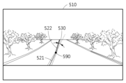
도 5는 일 실시예에 따라 산출된 변곡점에 기초한 영역 분할을 설명하는 도면이다.5 is a diagram explaining region division based on the calculated inflection point according to an exemplary embodiment.
일 실시예에 따르면 이미지 변환 장치는 입력 이미지(510)에서 차로 경계선에서 기울기 차이가 크게 변화하는 지점을 변곡점(590)으로 결정할 수 있다. 예를 들어, 이미지 변환 장치는 일부 경계선들 중 인접한 두 일부 경계선 간의 기울기 차이(slope difference)가 임계 차이(threshold difference)를 초과하는 경우에 응답하여, 인접한 두 일부 경계선 사이의 지점을 변곡점(590)으로 결정할 수 있다.According to an embodiment, the image conversion device may determine a point at which a gradient difference greatly changes at a road boundary in the
도 5에서 차로 경계선은 제1 일부 경계선(521) 및 제2 일부 경계선(522)으로 구분될 수 있다. 이미지 변환 장치는 제1 일부 경계선(521)의 기울기 및 제2 일부 경계선(522)의 기울기 간의 각도 차이(530)를 산출할 수 있다. 이미지 변환 장치는 각도 차이(530)가 임계 각도를 초과하는 경우에 응답하여, 제1 일부 경계선(521) 및 제2 일부 경계선(522)이 만나는 지점을 변곡점(590)으로 결정할 수 있다.In FIG. 5 , lane boundary lines may be divided into a first
이러한 변곡점(590)을 검출하는 동작의 예시를 하기 도 6에서 설명한다.An example of an operation for detecting such an
도 6은 일 실시예에 따른 변곡점 검출을 설명하는 도면이다.6 is a diagram illustrating detection of an inflection point according to an exemplary embodiment.
일 실시예에 따른 이미지 변환 장치는 식별된 차로 경계선(620)을 복수의 구간들(sections)로 분할할 수 있다. 이미지 변환 장치는 복수의 구간들의 각각에 나타난 일부 경계선(partial line)의 기울기(slope)를 산출할 수 있다. 이미지 변환 장치는 일부 경계선의 기울기에 기초하여, 변곡점을 계산할 수 있다. 구간(section)은 입력 이미지가 분할된 단위 영역을 나타낼 수 있다. 이미지 변환 장치는, 각 구간에 나타난 일부 경계선의 가장 아래 지점(bottom point)으로부터 가장 위 지점(top point) 사이의 기울기를 해당 구간에 대한 기울기로 결정할 수 있다. 각 구간에 나타난 일부 경계선의 기울기는 변곡점을 결정하는데 사용될 수 있다.The image conversion device according to an embodiment may divide the identified
예를 들어, 도 6에서 이미지 변환 장치는 입력 이미지(610)를 4개의 구간들로 분할할 수 있다. 이미지 변환 장치는 입력 이미지(610)에서 도로 영역을 4개의 구간들로 분할할 수 있다. 이미지 변환 장치는 차로 경계선(620)에 대해 각 구간에 대응하는 기울기를 산출할 수 있다. 이미지 변환 장치는 차로 경계선(620)의 제1 구간(611) 및 제2 구간(612) 사이의 기울기 차이에 대응하는 제1 각도(631), 제2 구간(612) 및 제3 구간(613) 사이의 기울기 차이에 대응하는 제2 각도(632), 제3 구간(613) 및 제4 구간(614) 사이의 기울기 차이에 대응하는 제3 각도(633)를 산출할 수 있다. 이미지 변환 장치는 두 구간들 사이의 기울기 차이에 대응하는 각도가 임계 각도를 초과하는 경우에 응답하여, 두 구간의 일부 경계선들이 서로 만나는 지점을 변곡점으로 결정할 수 있다. 도로의 경사도 변화에 따라, 변곡점이 나타나지 않거나, 2개 이상의 변곡점이 나타날 수도 있다.For example, in FIG. 6 , the image conversion device may divide the
도 6에서는 입력 이미지(610)를 4개의 구간들로 분할하는 예시를 설명하였으나, 이로 한정하는 것은 아니다. 이미지 변환 장치는 입력 이미지(610)를 m개의 구간들로 분할할 수도 있다. 여기서, m은 2이상의 정수일 수 있다.Although an example of dividing the
또한, 이미지 변환 장치는 입력 이미지(610)의 서로 인접한 3개의 구간들에서, 하단의 구간에 대응하는 기울기 및 상단의 구간에 대응하는 기울기 간의 기울기 차이가 구간 임계값(section threshold value)을 초과하는 경우에 응답하여, 중간 구간에 변곡점이 있는 것으로 결정할 수 있다. 이미지 변환 장치는 중간 구간을 복수의 서브 구간(sub section)으로 분할하고, 각 서브 구간에 대해 차로 경계선(620)의 기울기 변화가 임계값을 초과하는 지점을 변곡점으로 결정할 수 있다. 예를 들어, 도 6에서 제2 구간(612)에 대응하는 기울기 및 제4 구간(614)에 대응하는 기울기 간의 기울기 차이가 구간 임계값을 초과하는 경우에 응답하여, 이미지 변환 장치는 제3 구간(613) 내에 변곡점이 존재하는 것으로 판단할 수 있다. 이미지 변환 장치는 제3 구간(613)을 복수의 서브 구간들로 분할하여, 각 서브 구간의 기울기에 기초하여 변곡점을 검색할 수 있다.In addition, the image conversion device determines that the difference in slope between the slope corresponding to the lower section and the upper section in three adjacent sections of the
아울러, 이미지 변환 장치는 입력 이미지(610)에서 복수의 차로 경계선(620)들이 검출된 경우에 응답하여, 복수의 차로 경계선(620)들 중 입력 이미지(610)의 중심에 가장 가까운 차로 경계선(620)을 선택할 수 있다. 이미지 변환 장치는 선택된 차로 경계선(620)의 변곡점을 계산할 수 있다. 이미지의 중심에 가까울 차로 경계선(620)일수록, 보다 선명하고 이미지 획득부의 시야각을 벗어날 가능성이 상대적으로 낮기 때문이다.In addition, the image conversion device responds to a case in which a plurality of
일 실시예에 따른 이미지 변환 장치는 변곡점까지의 거리(예를 들어, 깊이(depth))를 결정할 수 있다. 이미지 변환 장치는 변곡점까지의 거리를 간접적으로 추정하거나, 직접 검출할 수도 있다.An image conversion device according to an embodiment may determine a distance (eg, depth) to an inflection point. The image conversion device may indirectly estimate or directly detect the distance to the inflection point.
아래 도 7에서는 상술한 바에 따라 분할된 영역 이미지들에 대한 소실점을 결정하는 동작을 설명한다.In FIG. 7 below, an operation of determining a vanishing point for region images divided as described above will be described.
도 7은 일 실시예에 따른 소실점의 결정을 설명하는 흐름도이다. 도 8은 일 실시예에 따른 영역 이미지들 별 소실점을 설명하는 도면이다.7 is a flowchart illustrating the determination of a vanishing point according to an exemplary embodiment. 8 is a diagram illustrating a vanishing point for each area image according to an exemplary embodiment.
일 실시예에 따른 이미지 변환 장치는 결정된 소실점들에 대해 입력 이미지 상에서의 픽셀 위치를 결정할 수 있다.The image conversion device according to an embodiment may determine pixel positions on the input image with respect to the determined vanishing points.
우선, 단계(721)에서 이미지 변환 장치는 각 영역 이미지에 나타난 차로 경계선들을 연장할 수 있다. 예를 들어, 도 8에 도시된 바와 같이 이미지 변환 장치는 입력 이미지에서 제1 영역 이미지의 차로 경계선들(821)을 연장할 수 있다. 이미지 변환 장치는 제2 영역 이미지의 차로 경계선들(822)을 연장할 수 있다.First of all, in
그리고 단계(722)에서 이미지 변환 장치는 연장된 차로 경계선들이 서로 교차하는 지점을 해당 영역 이미지에 대한 소실점으로 결정할 수 있다. 예를 들어, 이미지 변환 장치는 제1 영역 이미지의 연장된 차로 경계선들(821)이 교차하는 지점을 제1 소실점(841)으로 결정할 수 있다. 이미지 변환 장치는 제2 영역 이미지의 연장된 차로 경계선들(822)이 교차하는 지점을 제2 소실점(842)으로 결정할 수 있다. 이미지 변환 장치는 차로 경계선의 연장선들이 교차하는 지점의 입력 이미지 상의 픽셀 좌표를 소실점의 픽셀 좌표로 결정할 수 있다.In operation 722, the image conversion device may determine a point where the boundary lines of the extended lanes intersect with each other as a vanishing point for the corresponding area image. For example, the image conversion device may determine a point where the
참고로, 도 8에서는 각 영역 이미지에서 2개의 차로 경계선들이 연장되는 예시를 설명하였으나, 이로 한정하는 것은 아니다. 이미지 변환 장치는 도로를 구성하는 차로 개수에 따라, 3개 이상의 차로 경계선들을 연장시킬 수도 있다. 이 경우, 연장된 차로 경계선들이 단일 지점에서 교차할 수도 있으나, 복수의 지점에서 교차할 수도 있다. 일 실시예에 따른 이미지 변환 장치는 연장된 차로 경계선들이 복수의 지점들에서 교차하는 경우에 응답하여, 복수의 지점들에 기초하여 단일 지점을 소실점으로 결정할 수 있다. 예를 들어, 이미지 변환 장치는 연장된 차로 경계선들이 교차하는 복수의 지점들의 평균 지점(average point)을 해당 영역 이미지에 대한 소실점으로 결정할 수도 있다.For reference, an example in which boundary lines are extended by two lanes in each region image has been described in FIG. 8 , but is not limited thereto. The image conversion device may extend boundary lines of three or more lanes according to the number of lanes constituting the road. In this case, the extended lane boundary lines may intersect at a single point or may intersect at a plurality of points. The image conversion device according to an embodiment may determine a single point as a vanishing point based on the plurality of points in response to a case where the boundary lines of the extended lanes intersect at a plurality of points. For example, the image conversion device may determine an average point of a plurality of points where the boundary lines of the extended lanes intersect as a vanishing point for the corresponding area image.
이미지 변환 장치는 현재 차량이 주행 중인 차로의 차로 경계선을 연장함으로써 소실점을 검색할 수 있으나, 이로 한정하는 것은 아니다. 이미지 변환 장치는 다른 차로의 차로 경계선을 연장하여 소실점을 결정할 수도 있다.The image conversion device may search for a vanishing point by extending a lane boundary of a lane in which the vehicle is currently driving, but is not limited thereto. The image conversion device may determine the vanishing point by extending the boundary line of the other lane.
또한, 도 7에 도시된 바로 동작 순서를 한정하지 않는다. 예를 들어 이미지 변환 장치는 제1 영역 이미지에 대해 차로 경계선을 연장하여 제1 소실점을 결정하고, 그 후 제2 영역 이미지에 대해 차로 경계선을 연장하여 제2 소실점을 결정할 수도 있다.In addition, the operation sequence shown in FIG. 7 is not limited. For example, the image conversion device may determine a first vanishing point by extending a boundary line of a road with respect to the first area image, and then determine a second vanishing point by extending the boundary line with respect to the second area image.
아래 도 9에서 이미지 변환 장치는 각 영역 이미지마다 결정된 소실점 및 해당 영역 이미지의 시작 지점까지의 거리에 기초하여, 해당 영역 이미지에서의 픽셀 좌표를 물리 좌표로 변환하는 변환 관계를 계산할 수 있다.Referring to FIG. 9 below, the image conversion apparatus may calculate a conversion relationship for converting pixel coordinates in the corresponding region image into physical coordinates based on the vanishing point determined for each region image and the distance to the starting point of the corresponding region image.
도 9는 일 실시예에 따른 변환 관계의 계산 및 도로 프로파일 데이터의 생성을 설명하는 도면이다.9 is a diagram illustrating calculation of a conversion relationship and generation of road profile data according to an exemplary embodiment.
일 실시예에 따른 이미지 변환 장치는 이미지 획득부(901)를 기준으로, 입력 이미지(910)의 각 픽셀을 물리 좌표로 변환하는 변환 관계를 영역 이미지마다 산출할 수 있다. 예를 들어, 도 9에서 입력 이미지(910)는 제1 영역(911)에 대응하는 제1 영역 이미지 및 제2 영역(912)에 대응하는 제2 영역 이미지로 분할될 수 있다. 도 9에서 이미지 획득부(901)의 시야각의 중심축은 Zc축에 대응할 수 있다. Yc축은 이미지 획득부(901)가 위치된 지면에 대해 수직인 축을 나타낼 수 있다. Xc축은 Zc축 및 Yc축에 직교하는 축으로서, 이미지 변환 장치가 차량에 장착된 경우, 차량의 가로 축(lateral axis)에 대응할 수 있다. 도 9에서 이미지 획득부(901)의 물리 좌표가 (X1, Y1, Z1)으로 도시되었는데, 하기 수학식들에서는 이미지 획득부(901)의 해당 좌표를 원점으로 가정한다.The image conversion apparatus according to an embodiment may calculate a conversion relationship for each region image by converting each pixel of the
우선, 이미지 변환 장치는 이미지 획득부(901)에 가장 가까운 영역(예를 들어, 제1 영역(911))의 제1 영역 이미지의 픽셀 좌표를 물리 좌표로 변환하는 제1 변환 관계를 하기 수학식 1 내지 수학식 3과 같이 계산할 수 있다. 픽셀 좌표는 입력 이미지(910)에 나타난 타겟 지점의 입력 이미지(910) 상에서의 좌표를 나타낼 수 있다.First of all, the image conversion device converts the pixel coordinates of the first region image of the region closest to the image acquisition unit 901 (eg, the first region 911) into physical coordinates using the following equation It can be calculated as in 1 to Equation 3. The pixel coordinates may indicate coordinates on the
[수학식 1][Equation 1]
![]()
![]()
[수학식 2][Equation 2]
![]()
![]()
[수학식 3][Equation 3]
![]()
![]()
상술한 수학식 1 내지 수학식 3에서, x, y, 및 z는 각각 이미지 획득부의 위치를 원점으로 하는, 타겟 지점의 물리 위치로서 x좌표, y좌표, 및 z좌표를 나타낼 수 있다. 상수 y0는 차량에 장착된 이미지 획득부(901)의 지면으로부터의 높이를 나타낼 수 있다. 상술한 수학식 2 및 수학식 3에서 xim은 입력 이미지(910)에서 타겟 지점을 지시하는 픽셀 좌표의 x좌표, yim은 입력 이미지(910)에서 타겟 지점을 지시하는 픽셀 좌표의 y좌표를 나타낼 수 있다. 상술한 수학식 1 내지 수학식 3에서 px는 입력 이미지(910)에서 제1 영역 이미지의 소실점의 x좌표, py는 입력 이미지(910)에서 제1 영역 이미지의 소실점의 y좌표를 나타낼 수 있다. fx 는 카메라 파라미터로서, 예를 들어, 이미지 센서를 구성하는 센싱 엘리먼트(예를 들어, 픽셀 엘리먼트)의 x축 길이로 초점 길이를 나눈 값(예를 들어, 초점 길이를 x축에서의 픽셀 개수로 표현한 값)을 나타낼 수 있다. fy는 카메라 파라미터로서, 예를 들어, 센싱 엘리먼트의 y축 길이로 초점 길이를 나눈 값을 나타낼 수 있다. 예를 들어, 초점 길이 f=300um이고, 1개 픽셀 엘리먼트의 y축 길이가 2um인 경우, fy는 150 pixel이 될 수 있다.In the above-described Equations 1 to 3, x, y, and z are physical locations of the target point, the origin of which is the location of the image acquisition unit, and may represent x-coordinates, y-coordinates, and z-coordinates. The constant y 0 may represent the height of the
상술한 수학식 1 내지 수학식 3은 이미지 센서의 광축과 평행한 평면에 대해서만 적용될 수 있다. 예를 들어, 이미지 변환 장치는 차량으로부터 변곡점에 대응하는 타겟 지점까지의 제1 영역(911)에 속하는 픽셀 좌표들을 상술한 수학식 1 내지 수학식 3에 따른 변환 관계에 기초하여, 물리 좌표로 변환할 수 있다. 입력 이미지(910)에서 검출된 변곡점 이후의 영역에서는 도로(980)의 경사도가 변화하기 때문이다. 경사도는 상술한 바와 같이, 이미지 획득부의 광축에 평행한 평면(예를 들어, 이미지 획득부가 위치한 지면)에 대해 도로가 이루는 각도로서, 도 9에서는 ![]()
![]()
일 실시예에 따른 이미지 변환 장치는 분할된 영역 이미지들에 대해, 이미지 센서의 시야각의 중심축에 평행한 평면을 기준으로 하는 경사도(inclination level)를 소실점에 기초하여 산출할 수 있다. 이미지 변환 장치는 제2 영역(912)의 제2 영역 이미지에 대한 경사도를 하기 수학식 4와 같이 산출할 수 있다.The image conversion apparatus according to an embodiment may calculate an inclination level based on a plane parallel to a central axis of a viewing angle of an image sensor for divided area images based on a vanishing point. The image conversion device may calculate the inclination of the
[수학식 4][Equation 4]
![]()
![]()
상술한 수학식 4에서 ![]()
![]()
![]()
![]()
![]()
![]()
![]()
![]()
![]()
![]()
이미지 변환 장치는 영역 이미지들의 각각마다, 해당 영역 이미지에 대해 계산된 소실점, 카메라 파라미터, 카메라 높이, 해당 영역 이미지의 경사도, 및 해당 영역 이미지의 시작 깊이에 기초하여, 해당 영역 이미지에 속하는 타겟 지점(target point)의 2차원 픽셀 좌표를 3차원 좌표로 변환하는 변환 관계를 계산할 수 있다.For each of the area images, the image conversion device determines a target point belonging to the corresponding area image based on the vanishing point calculated for the corresponding area image, the camera parameter, the camera height, the inclination of the corresponding area image, and the starting depth of the corresponding area image. It is possible to calculate a conversion relationship that converts 2D pixel coordinates of a target point) into 3D coordinates.
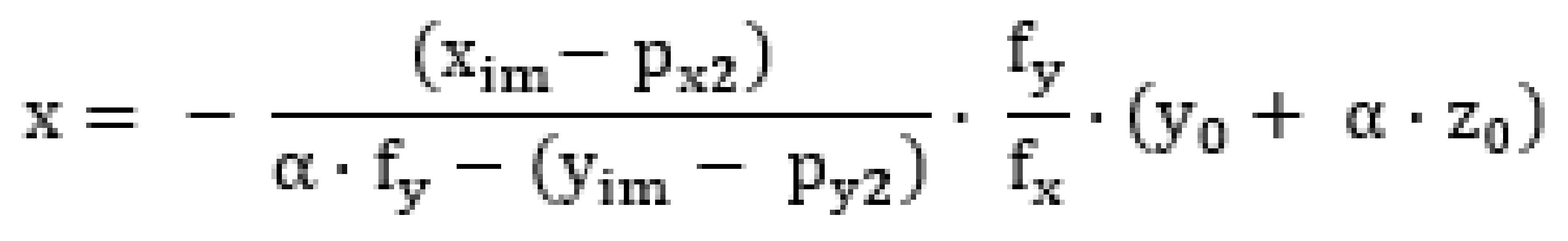
예를 들어, 이미지 변환 장치는 제2 영역(912)의 제2 영역 이미지의 픽셀 좌표를 물리 좌표로 변환하는 제2 변환 관계를 하기 수학식 5 내지 수학식 7과 같이 계산할 수 있다.For example, the image conversion device may calculate a second conversion relationship for converting pixel coordinates of the second region image of the
[수학식 5][Equation 5]
[수학식 6][Equation 6]
![]()
![]()
[수학식 7][Equation 7]
![]()
![]()
상술한 수학식 5 내지 수학식 7에서 xim은 입력 이미지(910)에서 타겟 지점의 x좌표, yim은 입력 이미지(910)에서 타겟 지점의 y좌표를 나타낼 수 있다. 상술한 수학식 5 내지 수학식 7에서 px2는 입력 이미지(910)에서 제2 영역 이미지의 소실점의 x좌표, py2는 입력 이미지(910)에서 제2 영역 이미지의 소실점의 y좌표를 나타낼 수 있다. fx 및 fy는 카메라 파라미터를 나타낼 수 있다. 상술한 수학식 7과 같이 타겟 지점의 높이는 이미지 획득부(901)의 높이인 상수 y0로부터 경사도 ![]()
![]()
참고로, 상술한 수학식 5 내지 수학식 7은 변곡점에 기초하여 분할된 복수의 영역 이미지들의 각각에 대한 범용 관계(예를 들어, 범용 식)을 나타낼 수 있다. 예를 들어, 제1 영역 이미지에 대응하는 타겟 지점들은 경사도 ![]()
![]()
따라서 이미지 변환 장치는 변곡점에 기초하여 분할된 복수의 영역 이미지들의 각각에 대한 변환 관계를 이미지 획득부(901)로부터 가까운 순서에 따라 순차적으로 계산할 수 있다. 예를 들어, 이미지 변환 장치는 임의의 영역 이미지에 대해 변곡점, 소실점, 및 상술한 수학식 5 내지 수학식 7에 따른 변환 관계를 계산한 후, 그 다음 영역 이미지에 대해 변곡점, 소실점 및 변환 관계를 계산할 수 있다. 이와 같이 이미지 변환 장치는 복수의 영역 이미지들에 대해 순차적으로 반복하여 변환 관계를 계산할 수 있다.Accordingly, the image conversion apparatus may sequentially calculate transformation relationships for each of the plurality of region images divided based on the inflection point in order of proximity from the
일 실시예에 따른 이미지 변환 장치는 입력 이미지(910)의 각 지점들(971)의 물리 위치(physical location)(972)에 대한 좌표를 포함하는 도로(980) 프로파일 데이터를 생성할 수 있다. 상술한 바와 같이 도로 프로파일 데이터는 입력 이미지(910)에 나타난 각 타겟 지점이 실제로 물리 세계에 배치되었을 때 도로(980)의 형상을 정의하는 프로파일 데이터일 수 있다. 도로 프로파일 데이터는 제2 뷰(예를 들어, 탑뷰)의 출력 이미지로 변환될 수도 있다.The image conversion device according to an embodiment may generate
일 실시예에 따른 이미지 변환 장치는 변곡점에 기초하여 구분된 영역 이미지들마다 최적화된 변환 관계를 산출함으로써, 정확한 도로 프로파일 데이터를 생성할 수 있다. 예를 들어, 이미지 변환 장치는 각 영역 이미지에 대해 객체(예를 들어, 차량, 건물, 가로수 및 동물 등)로 식별된 타겟 지점을 배제하고, 해당 영역 이미지에 대해 산출된 변환 관계를 나머지 타겟 지점에 대해 적용함으로써 도로 프로파일 데이터를 생성할 수 있다.The image conversion apparatus according to an embodiment may generate accurate road profile data by calculating an optimized conversion relationship for each region image divided based on an inflection point. For example, the image conversion device excludes target points identified as objects (eg, vehicles, buildings, roadside trees, animals, etc.) for each area image, and converts the conversion relationship calculated for the corresponding area image to the remaining target points. Road profile data can be generated by applying to .
도 10은 일 실시예에 따른 이미지 변환 장치의 구성을 설명하는 블록도이다.10 is a block diagram illustrating the configuration of an image conversion device according to an exemplary embodiment.
이미지 변환 장치(1000)는 이미지 획득부(1010), 프로세서(1020), 및 메모리(1030)를 포함할 수 있다.The
이미지 획득부(1010)는 전방 도로에 대한 입력 이미지를 획득할 수 있다. 이미지 획득부(1010)는 예를 들어, 이미지 센서로서 컬러 카메라로 구현될 수 있다. 다만, 이미지 센서의 종류를 이로 한정하는 것은 아니고, 적외선 센서 등으로 구현될 수도 있다.The
프로세서(1020)는 입력 이미지를 복수의 영역 이미지(region image)들로 분할할 수 있다. 프로세서(1020)는 분할된 영역 이미지들 중 각 영역 이미지에 대해 소실점을 결정할 수 있다. 프로세서(1020)는 소실점에 기초하여 각 영역 이미지의 2차원 좌표를 3차원 좌표로 변환하는 변환 관계를 계산할 수 있다. 프로세서(1020)는 각 영역 이미지마다 계산된 변환 관계에 기초하여, 분할된 영역 이미지들로부터 도로 프로파일 데이터를 생성할 수 있다. 다만, 프로세서(1020)의 동작을 이로 한정하는 것은 아니고, 프로세서(1020)는 도 1 내지 도 9에 따른 동작들을 수행할 수도 있다.The
메모리(1030)는 이미지 변환 방법을 수행하는데 요구되는 데이터를 임시적으로 또는 영구적으로 저장할 수 있다. 예를 들어, 메모리(1030)는 각 영역 이미지에 대해 산출된 변환 관계, 각 영역 이미지의 변환 관계에 기초하여 산출된 도로 프로파일 데이터 등을 저장할 수도 있다.The
이상에서 설명된 장치는 하드웨어 구성요소, 소프트웨어 구성요소, 및/또는 하드웨어 구성요소 및 소프트웨어 구성요소의 조합으로 구현될 수 있다. 예를 들어, 실시예들에서 설명된 장치 및 구성요소는, 예를 들어, 프로세서, 콘트롤러, ALU(arithmetic logic unit), 디지털 신호 프로세서(digital signal processor), 마이크로컴퓨터, FPA(field programmable array), PLU(programmable logic unit), 마이크로프로세서, 또는 명령(instruction)을 실행하고 응답할 수 있는 다른 어떠한 장치와 같이, 하나 이상의 범용 컴퓨터 또는 특수 목적 컴퓨터를 이용하여 구현될 수 있다. 처리 장치는 운영 체제(OS) 및 운영 체제 상에서 수행되는 하나 이상의 소프트웨어 애플리케이션을 수행할 수 있다. 또한, 처리 장치는 소프트웨어의 실행에 응답하여, 데이터를 접근, 저장, 조작, 처리 및 생성할 수도 있다. 이해의 편의를 위하여, 처리 장치는 하나가 사용되는 것으로 설명된 경우도 있지만, 해당 기술분야에서 통상의 지식을 가진 자는, 처리 장치가 복수 개의 처리 요소(processing element) 및/또는 복수 유형의 처리 요소를 포함할 수 있음을 알 수 있다. 예를 들어, 처리 장치는 복수 개의 프로세서 또는 하나의 프로세서 및 하나의 콘트롤러를 포함할 수 있다. 또한, 병렬 프로세서(parallel processor)와 같은, 다른 처리 구성(processing configuration)도 가능하다.The devices described above may be implemented as hardware components, software components, and/or a combination of hardware components and software components. For example, devices and components described in the embodiments may include, for example, a processor, a controller, an arithmetic logic unit (ALU), a digital signal processor, a microcomputer, a field programmable array (FPA), It may be implemented using one or more general purpose or special purpose computers, such as a programmable logic unit (PLU), microprocessor, or any other device capable of executing and responding to instructions. The processing device may run an operating system (OS) and one or more software applications running on the operating system. A processing device may also access, store, manipulate, process, and generate data in response to execution of software. For convenience of understanding, there are cases in which one processing device is used, but those skilled in the art will understand that the processing device includes a plurality of processing elements and/or a plurality of types of processing elements. It can be seen that it can include. For example, a processing device may include a plurality of processors or a processor and a controller. Other processing configurations are also possible, such as parallel processors.
소프트웨어는 컴퓨터 프로그램(computer program), 코드(code), 명령(instruction), 또는 이들 중 하나 이상의 조합을 포함할 수 있으며, 원하는 대로 동작하도록 처리 장치를 구성하거나 독립적으로 또는 결합적으로(collectively) 처리 장치를 명령할 수 있다. 소프트웨어 및/또는 데이터는, 처리 장치에 의하여 해석되거나 처리 장치에 명령 또는 데이터를 제공하기 위하여, 어떤 유형의 기계, 구성요소(component), 물리적 장치, 가상 장치(virtual equipment), 컴퓨터 저장 매체 또는 장치, 또는 전송되는 신호 파(signal wave)에 영구적으로, 또는 일시적으로 구체화(embody)될 수 있다. 소프트웨어는 네트워크로 연결된 컴퓨터 시스템 상에 분산되어서, 분산된 방법으로 저장되거나 실행될 수도 있다. 소프트웨어 및 데이터는 하나 이상의 컴퓨터 판독 가능 기록 매체에 저장될 수 있다.Software may include a computer program, code, instructions, or a combination of one or more of the foregoing, which configures a processing device to operate as desired or processes independently or collectively. You can command the device. Software and/or data may be any tangible machine, component, physical device, virtual equipment, computer storage medium or device, intended to be interpreted by or provide instructions or data to a processing device. , or may be permanently or temporarily embodied in a transmitted signal wave. Software may be distributed on networked computer systems and stored or executed in a distributed manner. Software and data may be stored on one or more computer readable media.
실시예에 따른 방법은 다양한 컴퓨터 수단을 통하여 수행될 수 있는 프로그램 명령 형태로 구현되어 컴퓨터 판독 가능 매체에 기록될 수 있다. 컴퓨터 판독 가능 매체는 프로그램 명령, 데이터 파일, 데이터 구조 등을 단독으로 또는 조합하여 포함할 수 있다. 매체에 기록되는 프로그램 명령은 실시예를 위하여 특별히 설계되고 구성된 것들이거나 컴퓨터 소프트웨어 당업자에게 공지되어 사용 가능한 것일 수도 있다. 컴퓨터 판독 가능 기록 매체의 예에는 하드 디스크, 플로피 디스크 및 자기 테이프와 같은 자기 매체(magnetic media), CD-ROM, DVD와 같은 광기록 매체(optical media), 플롭티컬 디스크(floptical disk)와 같은 자기-광 매체(magneto-optical media), 및 롬(ROM), 램(RAM), 플래시 메모리 등과 같은 프로그램 명령을 저장하고 수행하도록 특별히 구성된 하드웨어 장치가 포함된다. 프로그램 명령의 예에는 컴파일러에 의해 만들어지는 것과 같은 기계어 코드뿐만 아니라 인터프리터 등을 사용해서 컴퓨터에 의해서 실행될 수 있는 고급 언어 코드를 포함한다. 상기된 하드웨어 장치는 실시예의 동작을 수행하기 위해 하나 이상의 소프트웨어 모듈로서 작동하도록 구성될 수 있으며, 그 역도 마찬가지이다.The method according to the embodiment may be implemented in the form of program instructions that can be executed through various computer means and recorded on a computer readable medium. Computer readable media may include program instructions, data files, data structures, etc. alone or in combination. Program commands recorded on the medium may be specially designed and configured for the embodiment or may be known and usable to those skilled in computer software. Examples of computer-readable recording media include magnetic media such as hard disks, floppy disks and magnetic tapes, optical media such as CD-ROMs and DVDs, and magnetic media such as floptical disks. - includes hardware devices specially configured to store and execute program instructions, such as magneto-optical media, and ROM, RAM, flash memory, and the like. Examples of program instructions include high-level language codes that can be executed by a computer using an interpreter, as well as machine language codes such as those produced by a compiler. The hardware devices described above may be configured to operate as one or more software modules to perform the operations of the embodiments, and vice versa.
이상과 같이 실시예들이 비록 한정된 도면에 의해 설명되었으나, 해당 기술분야에서 통상의 지식을 가진 자라면 상기를 기초로 다양한 기술적 수정 및 변형을 적용할 수 있다. 예를 들어, 설명된 기술들이 설명된 방법과 다른 순서로 수행되거나, 및/또는 설명된 시스템, 구조, 장치, 회로 등의 구성요소들이 설명된 방법과 다른 형태로 결합 또는 조합되거나, 다른 구성요소 또는 균등물에 의하여 대치되거나 치환되더라도 적절한 결과가 달성될 수 있다. As described above, although the embodiments have been described with limited drawings, those skilled in the art can apply various technical modifications and variations based on the above. For example, the described techniques may be performed in an order different from the method described, and/or components of the described system, structure, device, circuit, etc. may be combined or combined in a different form than the method described, or other components may be used. Or even if it is replaced or substituted by equivalents, appropriate results can be achieved.
그러므로, 다른 구현들, 다른 실시예들 및 특허청구범위와 균등한 것들도 후술하는 특허청구범위의 범위에 속한다.Therefore, other implementations, other embodiments, and equivalents of the claims are within the scope of the following claims.
1000: 이미지 변환 장치
1010: 이미지 획득부
1020: 프로세서
1030: 메모리1000: image converter
1010: image acquisition unit
1020: processor
1030: memory
Claims (20)
전방 도로에 대한 입력 이미지를, 제1 영역 이미지 및 제2 영역 이미지를 포함하는 복수의 영역 이미지(region image)들로 분할(segment)하는 단계;
상기 제1 영역 이미지에 대응하는 제1 소실점을 결정하는 단계;
상기 제1 소실점과 상이하고 상기 제2 영역 이미지에 대응하는 제2 소실점을 결정하는 단계;
상기 제1 소실점에 기초하여 상기 제1 영역 이미지의 2차원 좌표를 3차원 좌표로 변환하는 제1 변환 관계(translation relation)를 계산하는 단계;
상기 제1 소실점 및 상기 제2 소실점에 기초하여 상기 제2 영역 이미지의 2차원 좌표를 3차원 좌표로 변환하는 제2 변환 관계를 계산하는 단계;및
상기 제1 변환 관계 및 상기 제2 변환 관계에 기초하여, 도로 프로파일 데이터(road profile data)를 생성하는 단계를 포함하는 이미지 변환 방법.In the image conversion method,
segmenting an input image of a road ahead into a plurality of region images including a first region image and a second region image;
determining a first vanishing point corresponding to the first area image;
determining a second vanishing point different from the first vanishing point and corresponding to the second area image;
calculating a first translation relation for converting 2D coordinates of the first area image into 3D coordinates based on the first vanishing point;
calculating a second transformation relationship for converting 2D coordinates of the second region image into 3D coordinates based on the first vanishing point and the second vanishing point; and
and generating road profile data based on the first transformation relationship and the second transformation relationship.
상기 입력 이미지를 복수의 영역 이미지들로 분할하는 단계는,
상기 입력 이미지로부터 차로 경계선을 식별하는 단계;
상기 식별된 차로 경계선의 변곡점(inflection point)을 계산하는 단계; 및
상기 계산된 변곡점을 기준으로 상기 입력 이미지를 복수의 영역 이미지들로 분할하는 단계
를 포함하는 이미지 변환 방법.According to claim 1,
Dividing the input image into a plurality of area images includes:
identifying a boundary line of a vehicle from the input image;
calculating an inflection point of the identified lane boundary line; and
Dividing the input image into a plurality of region images based on the calculated inflection point
Image conversion method comprising a.
상기 변곡점을 계산하는 단계는,
상기 식별된 차로 경계선을 복수의 구간들(sections)로 분할하는 단계;
상기 복수의 구간들의 각각에 나타난 일부 경계선(partial line)의 기울기(slope)를 산출하는 단계; 및
상기 일부 경계선의 기울기에 기초하여, 상기 변곡점을 계산하는 단계
를 포함하는 이미지 변환 방법.According to claim 2,
The step of calculating the inflection point is,
dividing the identified lane boundary into a plurality of sections;
Calculating a slope of a partial line appearing in each of the plurality of sections; and
Calculating the inflection point based on the slope of the partial boundary line
Image conversion method comprising a.
상기 변곡점을 계산하는 단계는,
일부 경계선들 중 인접한 두 일부 경계선 간의 기울기 차이(slope difference)가 임계 차이(threshold difference)를 초과하는 경우에 응답하여, 상기 인접한 두 일부 경계선 사이의 지점을 상기 변곡점으로 결정하는 단계
를 포함하는 이미지 변환 방법.According to claim 3,
The step of calculating the inflection point is,
Determining a point between two adjacent partial boundary lines as the inflection point in response to a case where a slope difference between two adjacent partial boundary lines exceeds a threshold difference.
Image conversion method comprising a.
상기 계산된 변곡점을 기준으로 상기 입력 이미지를 복수의 영역 이미지들로 분할하는 단계는,
상기 입력 이미지에서 상기 변곡점을 포함하는 수평선을 기준으로 상기 입력 이미지를 분할하는 단계
를 포함하는 이미지 변환 방법.According to claim 2,
Dividing the input image into a plurality of region images based on the calculated inflection point comprises:
Dividing the input image based on a horizontal line including the inflection point in the input image
Image conversion method comprising a.
상기 변곡점을 계산하는 단계는,
상기 입력 이미지에서 복수의 차로 경계선들이 검출된 경우에 응답하여, 상기 복수의 차로 경계선들 중 상기 입력 이미지의 중심에 가장 가까운 차로 경계선을 선택하는 단계; 및
상기 선택된 차로 경계선의 변곡점을 계산하는 단계
를 포함하는 이미지 변환 방법.According to claim 2,
The step of calculating the inflection point is,
selecting a lane boundary line closest to a center of the input image from among the plurality of lane boundary lines in response to detection of a plurality of lane boundary lines in the input image; and
Calculating an inflection point of the boundary line of the selected lane
Image conversion method comprising a.
상기 제1 소실점을 결정하는 단계는,
상기 제1 영역 이미지에 포함된 차로 경계선들을 연장하는 단계; 및
상기 연장된 차로 경계선들이 서로 교차하는 지점을 상기 제1 영역 이미지에 대한 상기 제1 소실점으로 결정하는 단계
를 포함하는 이미지 변환 방법.According to claim 1,
Determining the first vanishing point,
extending boundary lines of lanes included in the first area image; and
Determining a point where the boundary lines of the extended lane cross each other as the first vanishing point for the first area image
Image conversion method comprising a.
상기 연장된 차로 경계선들이 서로 교차하는 지점을 상기 제1 영역 이미지에 대한 상기 제1 소실점으로 결정하는 단계는,
상기 연장된 차로 경계선들이 복수의 지점들에서 교차하는 경우에 응답하여, 상기 복수의 지점들에 기초하여 단일 지점을 상기 제1 소실점으로 결정하는 단계
를 포함하는 이미지 변환 방법.According to claim 7,
Determining a point where the boundary lines of the extended lane cross each other as the first vanishing point for the first area image,
In response to a case where the extended lane boundary lines intersect at a plurality of points, determining a single point as the first vanishing point based on the plurality of points.
Image conversion method comprising a.
상기 제2 변환 관계를 계산하는 단계는,
상기 제2 영역 이미지에 대해, 이미지 센서의 시야각의 중심축에 평행한 평면을 기준으로 하는 경사도(inclination level)를 상기 제2 소실점에 기초하여 산출하는 단계
를 포함하는 이미지 변환 방법.According to claim 1,
Calculating the second transformation relationship,
Calculating an inclination level of the second area image based on a plane parallel to a central axis of a viewing angle of an image sensor based on the second vanishing point
Image conversion method comprising a.
상기 도로 프로파일 데이터를 생성하는 단계는,
상기 입력 이미지의 각 지점들의 물리 위치(physical location)에 대한 좌표를 포함하는 상기 도로 프로파일 데이터를 생성하는 단계
를 포함하는 이미지 변환 방법.According to claim 1,
Generating the road profile data,
Generating the road profile data including coordinates of physical locations of each point of the input image
Image conversion method comprising a.
Priority Applications (3)
| Application Number | Priority Date | Filing Date | Title |
|---|---|---|---|
| KR1020180122245A KR102519666B1 (en) | 2018-10-15 | 2018-10-15 | Device and method to convert image |
| US16/531,859 US11062153B2 (en) | 2018-10-15 | 2019-08-05 | Apparatus and method for converting image |
| CN201910969783.7A CN111046719A (en) | 2018-10-15 | 2019-10-12 | Apparatus and method for converting images |
Applications Claiming Priority (1)
| Application Number | Priority Date | Filing Date | Title |
|---|---|---|---|
| KR1020180122245A KR102519666B1 (en) | 2018-10-15 | 2018-10-15 | Device and method to convert image |
Publications (2)
| Publication Number | Publication Date |
|---|---|
| KR20200042100A KR20200042100A (en) | 2020-04-23 |
| KR102519666B1 true KR102519666B1 (en) | 2023-04-07 |
Family
ID=70161302
Family Applications (1)
| Application Number | Title | Priority Date | Filing Date |
|---|---|---|---|
| KR1020180122245A Active KR102519666B1 (en) | 2018-10-15 | 2018-10-15 | Device and method to convert image |
Country Status (3)
| Country | Link |
|---|---|
| US (1) | US11062153B2 (en) |
| KR (1) | KR102519666B1 (en) |
| CN (1) | CN111046719A (en) |
Families Citing this family (10)
| Publication number | Priority date | Publication date | Assignee | Title |
|---|---|---|---|---|
| KR102633140B1 (en) * | 2018-10-23 | 2024-02-05 | 삼성전자주식회사 | Method and apparatus of determining driving information |
| US10997740B2 (en) * | 2019-07-15 | 2021-05-04 | Here Global B.V. | Method, apparatus, and system for providing real-world distance information from a monocular image |
| CN111578839B (en) * | 2020-05-25 | 2022-09-20 | 阿波罗智联(北京)科技有限公司 | Obstacle coordinate processing method and device, electronic equipment and readable storage medium |
| KR20210148756A (en) * | 2020-06-01 | 2021-12-08 | 삼성전자주식회사 | Slope estimating apparatus and operating method thereof |
| KR102525387B1 (en) | 2020-11-24 | 2023-04-26 | 주식회사 넥스트칩 | Electronic device for determining irregularity of the ground, and operating method thereof |
| US11900516B2 (en) * | 2021-04-02 | 2024-02-13 | Carnegie Mellon University | System and method for pose tolerant feature extraction using generated pose-altered images |
| KR20230005779A (en) * | 2021-07-01 | 2023-01-10 | 오토브레인즈 테크놀로지스 리미티드 | Lane boundary detection |
| KR20230015114A (en) * | 2021-07-22 | 2023-01-31 | 삼성전자주식회사 | Method and apparatus for determining the slope of a road using a side camera of a vehicle |
| US12322110B2 (en) * | 2021-10-11 | 2025-06-03 | Autobrains Technologies Ltd | Generation of concepts for lane and road boundary prediction |
| CN116797517A (en) * | 2022-03-16 | 2023-09-22 | 小米汽车科技有限公司 | Object detection method, device and vehicle |
Citations (3)
| Publication number | Priority date | Publication date | Assignee | Title |
|---|---|---|---|---|
| JP2001160137A (en) * | 1999-09-22 | 2001-06-12 | Fuji Heavy Ind Ltd | Monitoring system distance correction device, and monitoring system vanishing point correction device |
| JP2011192226A (en) * | 2010-03-17 | 2011-09-29 | Hitachi Automotive Systems Ltd | On-board environment recognition device, and on-board environment recognition system |
| JP2017010553A (en) * | 2015-06-24 | 2017-01-12 | 株式会社リコー | Detection method and detection device for road boundary body |
Family Cites Families (16)
| Publication number | Priority date | Publication date | Assignee | Title |
|---|---|---|---|---|
| EP0827127B1 (en) * | 1996-08-28 | 2006-10-04 | Matsushita Electric Industrial Co., Ltd. | Local positioning apparatus, and method therefor |
| KR100472823B1 (en) | 2002-10-21 | 2005-03-08 | 학교법인 한양학원 | Method for detecting lane and system therefor |
| JP4355535B2 (en) | 2003-08-07 | 2009-11-04 | 株式会社岩根研究所 | 360 degree image conversion processing device |
| JP2005251106A (en) * | 2004-03-08 | 2005-09-15 | Mitsubishi Electric Corp | Lane recognition device |
| KR100663024B1 (en) | 2004-07-20 | 2006-12-28 | 엘지전자 주식회사 | Different image representation method by altitude |
| US8520935B2 (en) | 2010-02-04 | 2013-08-27 | Sony Corporation | 2D to 3D image conversion based on image content |
| US9533539B2 (en) * | 2011-10-20 | 2017-01-03 | GM Global Technology Operations LLC | Vehicle suspension system and method of using the same |
| CN103164851B (en) | 2011-12-09 | 2016-04-20 | 株式会社理光 | Lane segmentation object detecting method and device |
| KR101655204B1 (en) | 2014-06-20 | 2016-09-22 | 주식회사 세인전장 | Apparatus for image processing using 3dimension graphic model and method thereof |
| JP2017156965A (en) | 2016-03-01 | 2017-09-07 | トヨタ自動車株式会社 | Road region detection device |
| CN105869109B (en) | 2016-03-28 | 2018-12-07 | 长安大学 | Parking based on different height inverse projection face and leave object differentiating method |
| US10102435B2 (en) * | 2016-08-10 | 2018-10-16 | Omnivision Technologies, Inc. | Lane departure warning system and associated methods |
| CN106407893B (en) * | 2016-08-29 | 2019-11-22 | 东软集团股份有限公司 | A kind of method, apparatus and equipment detecting lane line |
| CN106991407B (en) * | 2017-04-10 | 2018-08-07 | 吉林大学 | A kind of method and device of lane detection |
| JP7044513B2 (en) * | 2017-10-23 | 2022-03-30 | 株式会社Soken | Road recognition device |
| KR102793522B1 (en) * | 2018-10-24 | 2025-04-09 | 삼성전자주식회사 | Localization method based on images and map data and apparatus thereof |
-
2018
- 2018-10-15 KR KR1020180122245A patent/KR102519666B1/en active Active
-
2019
- 2019-08-05 US US16/531,859 patent/US11062153B2/en active Active
- 2019-10-12 CN CN201910969783.7A patent/CN111046719A/en active Pending
Patent Citations (3)
| Publication number | Priority date | Publication date | Assignee | Title |
|---|---|---|---|---|
| JP2001160137A (en) * | 1999-09-22 | 2001-06-12 | Fuji Heavy Ind Ltd | Monitoring system distance correction device, and monitoring system vanishing point correction device |
| JP2011192226A (en) * | 2010-03-17 | 2011-09-29 | Hitachi Automotive Systems Ltd | On-board environment recognition device, and on-board environment recognition system |
| JP2017010553A (en) * | 2015-06-24 | 2017-01-12 | 株式会社リコー | Detection method and detection device for road boundary body |
Also Published As
| Publication number | Publication date |
|---|---|
| US11062153B2 (en) | 2021-07-13 |
| CN111046719A (en) | 2020-04-21 |
| US20200117920A1 (en) | 2020-04-16 |
| KR20200042100A (en) | 2020-04-23 |
Similar Documents
| Publication | Publication Date | Title |
|---|---|---|
| KR102519666B1 (en) | Device and method to convert image | |
| CN111024040B (en) | Distance Estimation Method and Device | |
| US11670087B2 (en) | Training data generating method for image processing, image processing method, and devices thereof | |
| KR102628654B1 (en) | Method and apparatus of indicating lane | |
| KR102541559B1 (en) | Method and apparatus of detecting objects of interest | |
| KR102267562B1 (en) | Device and method for recognition of obstacles and parking slots for unmanned autonomous parking | |
| KR102766548B1 (en) | Generating method and apparatus of 3d lane model | |
| CN111086521B (en) | Calibration method, calibration device, and non-transitory computer recording medium | |
| CN112631266A (en) | Method and device for mobile robot to sense obstacle information | |
| KR20200045696A (en) | Method and apparatus of determining driving information | |
| KR102667741B1 (en) | Method and apparatus of displaying 3d object | |
| EP2779025A2 (en) | Method and system for detecting road edge | |
| EP3324359B1 (en) | Image processing device and image processing method | |
| US10657392B2 (en) | Object detection device, object detection method, and program | |
| KR20200045701A (en) | Learning method of detecting vanishing point, method and apparatus of detecting vanishing point | |
| KR102003387B1 (en) | Method for detecting and locating traffic participants using bird's-eye view image, computer-readerble recording medium storing traffic participants detecting and locating program | |
| KR102525387B1 (en) | Electronic device for determining irregularity of the ground, and operating method thereof | |
| KR20240048748A (en) | Method and apparatus of determinig line information | |
| KR20220151572A (en) | Method and System for change detection and automatic updating of road marking in HD map through IPM image and HD map fitting | |
| KR20250011758A (en) | Method and apparatus with camera calibration | |
| KR102400726B1 (en) | Method and apparatus for detecting vehicle based on image | |
| JP2018194538A (en) | Information processing system and program | |
| KR20250053474A (en) | Distance determination method and device using the same | |
| KR101977503B1 (en) | Method and apparatus of detecting object based on distribution of road components |
Legal Events
| Date | Code | Title | Description |
|---|---|---|---|
| PA0109 | Patent application |
Patent event code: PA01091R01D Comment text: Patent Application Patent event date: 20181015 |
|
| PG1501 | Laying open of application | ||
| A201 | Request for examination | ||
| PA0201 | Request for examination |
Patent event code: PA02012R01D Patent event date: 20211015 Comment text: Request for Examination of Application Patent event code: PA02011R01I Patent event date: 20181015 Comment text: Patent Application |
|
| PE0902 | Notice of grounds for rejection |
Comment text: Notification of reason for refusal Patent event date: 20220922 Patent event code: PE09021S01D |
|
| E701 | Decision to grant or registration of patent right | ||
| PE0701 | Decision of registration |
Patent event code: PE07011S01D Comment text: Decision to Grant Registration Patent event date: 20230127 |
|
| GRNT | Written decision to grant | ||
| PR0701 | Registration of establishment |
Comment text: Registration of Establishment Patent event date: 20230404 Patent event code: PR07011E01D |
|
| PR1002 | Payment of registration fee |
Payment date: 20230405 End annual number: 3 Start annual number: 1 |
|
| PG1601 | Publication of registration |