KR102516040B1 - Detection device and detection method - Google Patents
Detection device and detection method Download PDFInfo
- Publication number
- KR102516040B1 KR102516040B1 KR1020217002930A KR20217002930A KR102516040B1 KR 102516040 B1 KR102516040 B1 KR 102516040B1 KR 1020217002930 A KR1020217002930 A KR 1020217002930A KR 20217002930 A KR20217002930 A KR 20217002930A KR 102516040 B1 KR102516040 B1 KR 102516040B1
- Authority
- KR
- South Korea
- Prior art keywords
- detection
- light
- polarization
- detected
- information
- Prior art date
- Legal status (The legal status is an assumption and is not a legal conclusion. Google has not performed a legal analysis and makes no representation as to the accuracy of the status listed.)
- Active
Links
Images


Classifications
-
- G—PHYSICS
- G01—MEASURING; TESTING
- G01N—INVESTIGATING OR ANALYSING MATERIALS BY DETERMINING THEIR CHEMICAL OR PHYSICAL PROPERTIES
- G01N21/00—Investigating or analysing materials by the use of optical means, i.e. using sub-millimetre waves, infrared, visible or ultraviolet light
- G01N21/84—Systems specially adapted for particular applications
- G01N21/88—Investigating the presence of flaws or contamination
- G01N21/95—Investigating the presence of flaws or contamination characterised by the material or shape of the object to be examined
- G01N21/9501—Semiconductor wafers
-
- G—PHYSICS
- G01—MEASURING; TESTING
- G01N—INVESTIGATING OR ANALYSING MATERIALS BY DETERMINING THEIR CHEMICAL OR PHYSICAL PROPERTIES
- G01N21/00—Investigating or analysing materials by the use of optical means, i.e. using sub-millimetre waves, infrared, visible or ultraviolet light
- G01N21/01—Arrangements or apparatus for facilitating the optical investigation
-
- G—PHYSICS
- G01—MEASURING; TESTING
- G01N—INVESTIGATING OR ANALYSING MATERIALS BY DETERMINING THEIR CHEMICAL OR PHYSICAL PROPERTIES
- G01N21/00—Investigating or analysing materials by the use of optical means, i.e. using sub-millimetre waves, infrared, visible or ultraviolet light
- G01N21/17—Systems in which incident light is modified in accordance with the properties of the material investigated
- G01N21/1717—Systems in which incident light is modified in accordance with the properties of the material investigated with a modulation of one or more physical properties of the sample during the optical investigation, e.g. electro-reflectance
-
- G—PHYSICS
- G01—MEASURING; TESTING
- G01N—INVESTIGATING OR ANALYSING MATERIALS BY DETERMINING THEIR CHEMICAL OR PHYSICAL PROPERTIES
- G01N21/00—Investigating or analysing materials by the use of optical means, i.e. using sub-millimetre waves, infrared, visible or ultraviolet light
- G01N21/17—Systems in which incident light is modified in accordance with the properties of the material investigated
- G01N21/21—Polarisation-affecting properties
-
- G—PHYSICS
- G01—MEASURING; TESTING
- G01N—INVESTIGATING OR ANALYSING MATERIALS BY DETERMINING THEIR CHEMICAL OR PHYSICAL PROPERTIES
- G01N21/00—Investigating or analysing materials by the use of optical means, i.e. using sub-millimetre waves, infrared, visible or ultraviolet light
- G01N21/84—Systems specially adapted for particular applications
- G01N21/86—Investigating moving sheets
-
- G—PHYSICS
- G01—MEASURING; TESTING
- G01N—INVESTIGATING OR ANALYSING MATERIALS BY DETERMINING THEIR CHEMICAL OR PHYSICAL PROPERTIES
- G01N21/00—Investigating or analysing materials by the use of optical means, i.e. using sub-millimetre waves, infrared, visible or ultraviolet light
- G01N21/84—Systems specially adapted for particular applications
- G01N21/88—Investigating the presence of flaws or contamination
- G01N21/8806—Specially adapted optical and illumination features
-
- G—PHYSICS
- G01—MEASURING; TESTING
- G01N—INVESTIGATING OR ANALYSING MATERIALS BY DETERMINING THEIR CHEMICAL OR PHYSICAL PROPERTIES
- G01N21/00—Investigating or analysing materials by the use of optical means, i.e. using sub-millimetre waves, infrared, visible or ultraviolet light
- G01N21/84—Systems specially adapted for particular applications
- G01N21/88—Investigating the presence of flaws or contamination
- G01N21/8851—Scan or image signal processing specially adapted therefor, e.g. for scan signal adjustment, for detecting different kinds of defects, for compensating for structures, markings, edges
-
- G—PHYSICS
- G01—MEASURING; TESTING
- G01N—INVESTIGATING OR ANALYSING MATERIALS BY DETERMINING THEIR CHEMICAL OR PHYSICAL PROPERTIES
- G01N21/00—Investigating or analysing materials by the use of optical means, i.e. using sub-millimetre waves, infrared, visible or ultraviolet light
- G01N21/84—Systems specially adapted for particular applications
- G01N21/88—Investigating the presence of flaws or contamination
- G01N21/95—Investigating the presence of flaws or contamination characterised by the material or shape of the object to be examined
- G01N21/952—Inspecting the exterior surface of cylindrical bodies or wires
-
- G—PHYSICS
- G01—MEASURING; TESTING
- G01N—INVESTIGATING OR ANALYSING MATERIALS BY DETERMINING THEIR CHEMICAL OR PHYSICAL PROPERTIES
- G01N21/00—Investigating or analysing materials by the use of optical means, i.e. using sub-millimetre waves, infrared, visible or ultraviolet light
- G01N21/01—Arrangements or apparatus for facilitating the optical investigation
- G01N2021/0106—General arrangement of respective parts
- G01N2021/0112—Apparatus in one mechanical, optical or electronic block
-
- G—PHYSICS
- G01—MEASURING; TESTING
- G01N—INVESTIGATING OR ANALYSING MATERIALS BY DETERMINING THEIR CHEMICAL OR PHYSICAL PROPERTIES
- G01N21/00—Investigating or analysing materials by the use of optical means, i.e. using sub-millimetre waves, infrared, visible or ultraviolet light
- G01N21/17—Systems in which incident light is modified in accordance with the properties of the material investigated
- G01N21/1717—Systems in which incident light is modified in accordance with the properties of the material investigated with a modulation of one or more physical properties of the sample during the optical investigation, e.g. electro-reflectance
- G01N2021/1725—Modulation of properties by light, e.g. photoreflectance
-
- G—PHYSICS
- G01—MEASURING; TESTING
- G01N—INVESTIGATING OR ANALYSING MATERIALS BY DETERMINING THEIR CHEMICAL OR PHYSICAL PROPERTIES
- G01N21/00—Investigating or analysing materials by the use of optical means, i.e. using sub-millimetre waves, infrared, visible or ultraviolet light
- G01N21/84—Systems specially adapted for particular applications
- G01N21/88—Investigating the presence of flaws or contamination
- G01N21/8806—Specially adapted optical and illumination features
- G01N2021/8848—Polarisation of light
-
- G—PHYSICS
- G01—MEASURING; TESTING
- G01N—INVESTIGATING OR ANALYSING MATERIALS BY DETERMINING THEIR CHEMICAL OR PHYSICAL PROPERTIES
- G01N21/00—Investigating or analysing materials by the use of optical means, i.e. using sub-millimetre waves, infrared, visible or ultraviolet light
- G01N21/84—Systems specially adapted for particular applications
- G01N21/88—Investigating the presence of flaws or contamination
- G01N21/8851—Scan or image signal processing specially adapted therefor, e.g. for scan signal adjustment, for detecting different kinds of defects, for compensating for structures, markings, edges
- G01N2021/8854—Grading and classifying of flaws
- G01N2021/8861—Determining coordinates of flaws
-
- G—PHYSICS
- G01—MEASURING; TESTING
- G01N—INVESTIGATING OR ANALYSING MATERIALS BY DETERMINING THEIR CHEMICAL OR PHYSICAL PROPERTIES
- G01N21/00—Investigating or analysing materials by the use of optical means, i.e. using sub-millimetre waves, infrared, visible or ultraviolet light
- G01N21/84—Systems specially adapted for particular applications
- G01N21/88—Investigating the presence of flaws or contamination
- G01N21/8851—Scan or image signal processing specially adapted therefor, e.g. for scan signal adjustment, for detecting different kinds of defects, for compensating for structures, markings, edges
- G01N2021/8854—Grading and classifying of flaws
- G01N2021/8874—Taking dimensions of defect into account
-
- G—PHYSICS
- G01—MEASURING; TESTING
- G01N—INVESTIGATING OR ANALYSING MATERIALS BY DETERMINING THEIR CHEMICAL OR PHYSICAL PROPERTIES
- G01N2201/00—Features of devices classified in G01N21/00
- G01N2201/06—Illumination; Optics
- G01N2201/068—Optics, miscellaneous
- G01N2201/0683—Brewster plate; polarisation controlling elements
-
- G—PHYSICS
- G01—MEASURING; TESTING
- G01N—INVESTIGATING OR ANALYSING MATERIALS BY DETERMINING THEIR CHEMICAL OR PHYSICAL PROPERTIES
- G01N2201/00—Features of devices classified in G01N21/00
- G01N2201/10—Scanning
- G01N2201/104—Mechano-optical scan, i.e. object and beam moving
- G01N2201/1042—X, Y scan, i.e. object moving in X, beam in Y
Landscapes
- Physics & Mathematics (AREA)
- Health & Medical Sciences (AREA)
- Life Sciences & Earth Sciences (AREA)
- Chemical & Material Sciences (AREA)
- Analytical Chemistry (AREA)
- Biochemistry (AREA)
- General Health & Medical Sciences (AREA)
- General Physics & Mathematics (AREA)
- Immunology (AREA)
- Pathology (AREA)
- Engineering & Computer Science (AREA)
- Computer Vision & Pattern Recognition (AREA)
- Signal Processing (AREA)
- Investigating Materials By The Use Of Optical Means Adapted For Particular Applications (AREA)
- Length Measuring Devices By Optical Means (AREA)
- Investigating Or Analysing Materials By Optical Means (AREA)
Abstract
본 발명은 검출 장치 및 검출 방법을 제공한다. 검출 장치는 검출될 부품의 표면에 반사된 제 1 및 제 2 에코 광의 간섭에 의해 형성된 신호 광을 사용하여 제 1 검출 장치에 의해서 검출될 부품상의 샘플링 위치에 대응하는 신호 광의 제 1 광 세기 분포 정보를 얻고 세기 분포에 따라서 신호 광의 위상 분포를 얻고 검출될 부품의 결함 분포 데이터를 얻는다. 이들 중, 제 1 검출 기구는 2 개 초과의 편광 검출기 또는 비-편광 검출기 및 적어도 1 개의 편광 검출기를 포함한다. 본 발명은 신호 광의 편광 상태 분석을 효과적으로 달성하고, 종 방향으로 검출될 부품의 고정밀 검출을 달성하고, 우수한 신뢰성, 높은 안정성 및 신속한 검출 속도의 장점을 가질 수 있다.The present invention provides a detection device and a detection method. The detection device uses the signal light formed by the interference of the first and second echo lights reflected on the surface of the component to be detected to obtain first light intensity distribution information of the signal light corresponding to the sampling position on the component to be detected by the first detection device. Obtain the phase distribution of the signal light according to the intensity distribution and obtain the defect distribution data of the part to be detected. Among these, the first detection mechanism includes more than two polarization detectors or non-polarization detectors and at least one polarization detector. The present invention can effectively achieve polarization state analysis of signal light, achieve high-precision detection of a part to be detected in the longitudinal direction, and have advantages of excellent reliability, high stability, and rapid detection speed.
Description
본 발명은 광학 검출의 기술 분야, 특히 검출 장치(device) 및 검출 방법에 관한 것이다.The present invention relates to the technical field of optical detection, in particular to a detection device and a detection method.
웨이퍼 결함 검출은 홈(groove), 입자(particle), 스크래치(scratche), 결함 위치와 같은 결함이 있는 지의 여부를 검출하는 것을 지칭한다. 칩 기판과 같은 웨이퍼 결함의 검출은 널리 사용되며, 웨이퍼에 결함이 있으면 웨이퍼 상의 고가의 공정이 실패하게 할 수 있으므로, 웨이퍼 생산자는 종종 결함 검출을 수행하여 제품 수율을 보장하며, 웨이퍼 사용자는 또한, 사용하기 전에 제품 수율을 보장하기 위해서 웨이퍼의 결함 정도를 결정할 필요가 있으며; 웨이퍼 결함의 검출은 반도체 장치에 추가 오염이 있는 지의 여부를 테스트하는데도 종종 사용된다.Wafer defect detection refers to detecting whether there are defects such as grooves, particles, scratches, and defect locations. The detection of wafer defects such as chip substrates is widely used, and defects on the wafer can cause expensive processes on the wafer to fail, so wafer producers often perform defect detection to ensure product yield, and wafer users also: It is necessary to determine the degree of defects of wafers before use to ensure product yield; Detection of wafer defects is also often used to test whether a semiconductor device has additional contamination.
광학 검출 방법은 검출 속도가 빠르고 추가 오염이 없는 특성을 가지며 부품(component) 결함 검출에 널리 사용된다. 그러나, 광 산란 방법과 같은 웨이퍼 결함을 검출하기 위한 기존의 광학 검출 방법은 웨이퍼 축 방향(웨이퍼 표면에 수직인 방향)으로 낮은 검출 정확도를 가진다.The optical detection method has a high detection speed and no additional contamination, and is widely used for detecting component defects. However, existing optical detection methods for detecting wafer defects, such as the light scattering method, have low detection accuracy in the wafer axial direction (direction perpendicular to the wafer surface).
이를 고려하여, 본 발명의 목적은 종래 기술에서 웨이퍼 축선으로의 낮은 검출 정확도에 대한 기술적 문제를 효과적으로 개선할 수 있는 결함 검출 장치 및 검출 방법을 제공하는 것이다.In view of this, an object of the present invention is to provide a defect detection device and detection method capable of effectively improving the technical problem of low detection accuracy along the wafer axis in the prior art.
제 1 양태에서, 본 발명의 실시예는 광 발생 및 변조(modulating) 기구(apparatus) 그리고 제 1 검출 기구를 포함하는 결함 검출 장치를 제공한다. 광 발생 및 변조 장치는 제 1 편광이 제 1 에코 광을 형성하기 위해서 검출될 부품의 검출 표면에 의해 반사되고, 제 2 편광이 제 2 에코 광을 형성하기 위해서 검출될 부품의 검출 표면에 의해 반사되도록, 제 1 편광 및 제 2 편광을 발생하는데 사용되며, 제 1 에코 광 및 제 2 에코 광이 신호 광을 형성하기 위해서 간섭되며, 제 1 편광과 제 2 편광의 중심들 사이에 미리 설정된(preset) 전단량(shear amount)이 있다. 제 1 검출 장치는 신호 광의 제 1 광 세기 분포 정보를 획득하는데 사용되며, 제 1 검출 기구가 모두 편광 검출기인 둘 이상의 검출기를 포함하며, 상이한 편광 검출기의 편광 검출 방향이 상이하거나, 둘 이상의 검출기가 비-편광 검출기 및 적어도 하나의 편광 검출기를 포함한다.In a first aspect, an embodiment of the present invention provides a defect detection device comprising a light generating and modulating apparatus and a first detection apparatus. The light generating and modulating device is such that a first polarization is reflected by the detection surface of the component to be detected to form a first echo light and a second polarization is reflected by the detection surface of the component to be detected to form a second echo light. It is used to generate the first polarization and the second polarization, and the first echo light and the second echo light are interfered to form the signal light, which is preset between the centers of the first polarization and the second polarization. ) has a shear amount. The first detection device is used to obtain first light intensity distribution information of the signal light, and includes two or more detectors, the first detection mechanism being both polarization detectors, the polarization detection directions of different polarization detectors are different, or the two or more detectors are a non-polarization detector and at least one polarization detector.
또한, 제 1 검출 기구는 검출될 부품의 표면을 스캔하는데 사용되는 제 1 검출 영역을 포함하며, 제 1 검출 영역은 복수의 제 1 검출 셀 영역을 포함하며, 복수의 제 1 검출 셀 영역의 배열 방향은 검출될 부품 표면상의 제 1 검출 영역의 스캐닝 방향과 수직이 아니며, 검출기는 상이한 제 1 검출 셀 영역에 대응하는 검출될 표면으로부터 다시 반사된 신호 광을 별도로(separately) 검출하는데 사용된다.In addition, the first detection mechanism includes a first detection area used to scan a surface of a part to be detected, the first detection area including a plurality of first detection cell areas, and an arrangement of the plurality of first detection cell areas. The direction is not perpendicular to the scanning direction of the first detection area on the part surface to be detected, and the detector is used to separately detect the signal light reflected back from the surface to be detected corresponding to the different first detection cell areas.
또한, 복수의 제 1 검출 셀 영역의 배열 방향은 검출될 부품 표면상의 제 1 검출 영역의 스캐닝 방향에 평행하다.Further, the arrangement direction of the plurality of first detection cell regions is parallel to the scanning direction of the first detection regions on the surface of the component to be detected.
또한, 제 1 검출 영역은 스트립 형상이며, 제 1 검출 영역의 연장 방향은 검출될 부품 표면상의 제 1 검출 영역의 스캐닝 방향에 수직이다.Further, the first detection region is strip-shaped, and the extension direction of the first detection region is perpendicular to the scanning direction of the first detection region on the surface of the part to be detected.
또한, 검출될 부품의 검출 표면이 원형일 때, 제 1 검출 영역은 검출될 부품 표면의 반경 방향을 따라서 연장하며, 검출될 부품 표면상의 제 1 검출 영역의 스캐닝 방향은 검출될 표면의 직경 방향에 수직이다.Further, when the detection surface of the part to be detected is circular, the first detection area extends along the radial direction of the surface of the part to be detected, and the scanning direction of the first detection area on the surface of the part to be detected is in the radial direction of the surface to be detected. It is vertical.
또한, 제 1 편광 및 제 2 편광은 검출될 부품의 표면에 검출 스폿을 형성하는데 사용되며, 검출될 부품 표면상의 제 1 검출 영역의 스캐닝 방향에서 검출 스폿의 크기는 제 1 검출 영역의 크기보다 크거나 같다.Further, the first polarization and the second polarization are used to form a detection spot on the surface of the component to be detected, and the size of the detection spot in the scanning direction of the first detection region on the surface of the component to be detected is larger than the size of the first detection region. or the same
또한, 각각의 편광 검출기는 편광 라인 검출기이며, 비-편광 검출기는 라인 검출기이다. 편광 검출기를 사용하면 단일 샘플링의 검사 영역을 증가시키고 검출 효율을 더욱 개선할 수 있다.Also, each polarization detector is a polarization line detector, and each non-polarization detector is a line detector. Using a polarization detector can increase the inspection area of a single sampling and further improve detection efficiency.
또한, 편광 검출기의 수가 2 개일 때, 2 개의 편광 검출기의 편광 검출 방향은 서로 수직이다.Also, when the number of polarization detectors is two, the polarization detection directions of the two polarization detectors are perpendicular to each other.
또한, 제 1 검출 기구는 제 1 편광 검출기, 제 2 편광 검출기 및 제 3 편광 검출기를 포함한 3 개 이상의 편광 검출기를 포함할 때, 여기서 제 3 편광 검출기와 제 1 편광 검출기의 편광 검출 방향들 사이의 각도는 360°/n이며, n은 3보다 크거나 같은 정수이며, n은 편광 검출기의 수이다. 3 개 초과의 편광 검출기를 사용하면 더욱 정확한 높이 검출 결과를 얻기 위해서 신호 광의 위상 정보를 더욱 정확하게 얻을 수 있다.Further, when the first detection mechanism includes three or more polarization detectors including a first polarization detector, a second polarization detector, and a third polarization detector, here, the distance between the polarization detection directions of the third polarization detector and the first polarization detector is The angle is 360°/n, where n is an integer greater than or equal to 3, and n is the number of polarization detectors. If more than three polarization detectors are used, phase information of the signal light can be obtained more accurately in order to obtain a more accurate height detection result.
또한, 제 1 편광 검출기 및 제 3 편광 검출기의 편광 검출 방향은 서로 수직이며, 제 3 편광 검출기와 제 2 편광 검출기의 편광 검출 방향들 사이의 각도는 45°이다.Further, polarization detection directions of the first polarization detector and the third polarization detector are perpendicular to each other, and an angle between the polarization detection directions of the third polarization detector and the second polarization detector is 45°.
또한, 제 1 검출 기구가 비-편광 검출기 및 적어도 하나의 편광 검출기를 포함할 때, 편광 검출기의 수는 2 개 이상이며, 두 개의 편광 검출기의 편광 검출 방향들 사이의 각도는 예각 또는 둔각이다.Further, when the first detection mechanism includes a non-polarization detector and at least one polarization detector, the number of polarization detectors is two or more, and an angle between polarization detection directions of the two polarization detectors is an acute angle or an obtuse angle.
또한, 광 발생 및 변조 기구는:Additionally, the light generating and modulating mechanism:
제 1 편광 및 제 2 편광을 발생하는데 사용되는 제 1 광 발생 수단으로서, 제 1 편광과 제 2 편광의 중심들 사이에 미리 설정된 전단량이 있으며, 제 1 편광은 제 1 에코 광을 형성하기 위해서 검출될 부품의 표면에 의해 반사되며, 제 2 편광은 제 2 에코 광을 형성하기 위해서 검출될 부품의 표면에 의해 반사되며, 제 1 및 제 2 에코 광이 조합(combine)되는, 제 1 광 발생 수단; 및As the first light generating means used to generate the first polarized light and the second polarized light, there is a preset amount of shear between the centers of the first polarized light and the second polarized light, and the first polarized light is detected to form the first echo light. first light generating means, the second polarized light is reflected by the surface of the component to be detected to form a second echo light, wherein the first and second echo light are combined; ; and
제 1 에코 광과 제 2 에코 광이 신호 광을 형성하기 위해서 간섭되도록 제 1 에코 광 및 제 2 에코 광의 편광 방향을 변조하는데 사용되는 편광 제어기를 포함한다.and a polarization controller used to modulate polarization directions of the first echo light and the second echo light such that the first echo light and the second echo light interfere to form a signal light.
또한, 제 1 광 발생 수단은 검출 광 발생 모듈 및 빔 조정 모듈을 포함하며, 검출 광 발생 모듈은 빔 조정 모듈에 결합(couple)된다.Also, the first light generating means includes a detection light generating module and a beam adjusting module, and the detection light generating module is coupled to the beam adjusting module.
검출 광 발생 모듈은 제 1 검출 광을 발생하는데 사용된다.A detection light generating module is used to generate the first detection light.
빔 조정 모듈은 제 1 검출 광을 제 1 편광과 제 2 편광으로 분할하고 제 1 및 제 2 에코 광을 조합하는데 사용된다.A beam steering module is used to split the first detection light into a first polarization and a second polarization and combine the first and second echo lights.
또한, 검출 광 발생 모듈은 제 1 광원 및 빔 확장 형상화 수단을 포함하며, 제 1 광원은 제 1 검출 광을 발생하는데 사용되며, 빔 확장 형상화 수단은 검출될 부품 표면상의 스폿의 형상 및 크기를 제어하는데 사용된다.In addition, the detection light generation module includes a first light source and beam expansion shaping means, the first light source is used to generate the first detection light, and the beam expansion shaping means controls the shape and size of a spot on the surface of the part to be detected. used to do
또한, 빔 조정 모듈은 복굴절 결정체를 포함한다.Also, the beam steering module includes a birefringent crystal.
또한, 제 1 검출 광은 선형 편광, 원형 편광 또는 타원 편광이다. 검출 광이 선형 편광일 때, 후속 복조(demodulation) 공정을 단순화하는데 유리하다.Also, the first detection light is linearly polarized light, circularly polarized light or elliptically polarized light. When the detection light is linearly polarized, it is advantageous to simplify the subsequent demodulation process.
또한, 결함 검출 장치는 제 1 처리 기구를 더 포함하며, 제 1 검출 기구는 제 1 처리 기구에 전기적으로 연결된다. 제 1 처리 기구는 신호 광의 제 1 광 세기 분포 정보에 따라서 검출될 부품의 결함 정보를 획득하는데 사용된다.In addition, the defect detection device further includes a first processing mechanism, and the first detection mechanism is electrically connected to the first processing mechanism. A first processing mechanism is used to obtain defect information of a part to be detected according to the first light intensity distribution information of the signal light.
또한, 제 1 처리 기구는:Additionally, the first processing mechanism:
신호 광의 제 1 광 세기 분포 정보에 따라서 신호 광의 초기 정보를 획득하는데 사용되는 신호 복조 모듈;a signal demodulation module used to obtain initial information of the signal light according to the first light intensity distribution information of the signal light;
잡음 정보를 획득하기 위해서 신호 광의 제 1 광 세기 분포 정보에 대해 저역 통과(low-pass) 필터링 처리를 수행하는데 사용되는 잡음 획득 모듈; 및a noise acquisition module used to perform low-pass filtering processing on the first light intensity distribution information of the signal light to obtain noise information; and
초기 정보 및 잡음 정보에 따라서 검출될 부품의 결함 정보를 획득하는데 사용되는 타겟 정보 획득 모듈을 포함한다.and a target information acquisition module used to acquire defect information of a part to be detected according to initial information and noise information.
또한, 초기 정보는 신호 광의 초기 위상 정보를 포함하며, 잡음 정보는 잡음 위상 정보를 포함한다. 타겟 정보 획득 모듈은 타겟 위상 정보를 얻기 위해서 초기 위상 정보 및 잡음 위상 정보에 대해 차등 처리를 수행하는데 사용되는 타겟 위상 획득 서브 모듈; 및 타겟 위상 정보에 따라서 검출될 부품의 결함 정보를 획득하는데 사용되는 결함 정보 획득 서브 모듈을 포함한다. 이러한 방식으로, 신호 광에 포함된 위상 잡음은 필터링될 수 있어서, 검출 결과의 정확도를 개선하는데 유리하다.Also, the initial information includes initial phase information of signal light, and the noise information includes noise phase information. The target information obtaining module includes a target phase obtaining submodule, which is used to perform differential processing on initial phase information and noise phase information to obtain target phase information; and a defect information obtaining submodule used to acquire defect information of a part to be detected according to target phase information. In this way, phase noise included in signal light can be filtered out, which is advantageous for improving the accuracy of detection results.
또한, 타겟 정보 획득 모듈은 미리 설정된 위상 정보 및 미리 설정된 결함 정보 사이의 대응 관계를 결정하기 위한 미리 설정된 위상 정보 및 미리 설정된 결함 정보를 포함하는 결함 표준 라이브러리를 더 포함하며; 결함 정보 획득 서브-모듈은 미리 설정된 결함 정보를 획득하고 검출될 부품의 검출 정보를 얻기 위해서 타겟 위상 정보에 따라 결함 표준 라이브러리에서 검색하는데 특별히 사용된다.In addition, the target information acquisition module further includes a defect standard library containing the preset phase information and the preset defect information for determining a correspondence between the preset phase information and the preset defect information; The defect information acquisition sub-module is specially used for acquiring preset defect information and searching in the defect standard library according to the target phase information to obtain detection information of a part to be detected.
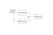
또한, 결함 검출 장치는 검출될 부품 표면의 산란 광을 수집하고, 산란 광의 제 2 광 세기 분포 정보를 획득하는데 사용되는 제 2 검출 기구; 및 제 1 광 세기 분포 정보에 따라서 검출될 부품의 제 1 결함 정보를 획득하고, 제 2 광 세기 분포 정보에 따라서 검출될 부품의 제 2 결함 정보를 획득하고, 제 1 결함 정보 및 제 2 결함 정보에 기초하여 검출될 부품의 타겟 결함 정보를 획득하는데 사용되는 제 2 처리 기구를 더 포함한다. 이러한 방식으로, 이중 채널 검출이 실현될 수 있으며, 이는 결함 검출의 종 방향 정확도 개선에 기초하여 수평 해상도를 개선하는데 유리하다.In addition, the defect detection apparatus includes a second detection mechanism used to collect scattered light on the surface of the component to be detected and obtain second light intensity distribution information of the scattered light; and obtaining first defect information of the component to be detected according to the first light intensity distribution information, obtaining second defect information of the component to be detected according to the second light intensity distribution information, and obtaining the first defect information and the second defect information. and a second processing mechanism used to obtain target defect information of the component to be detected based on the . In this way, dual-channel detection can be realized, which is advantageous for improving horizontal resolution based on improving longitudinal accuracy of defect detection.
또한, 전술한 결함 검출 장치는 제 2 검출 광을 발생하고, 제 2 검출 광이 산란 광을 형성하기 위해서 검출될 부품의 표면에 의해 산란되게 하는데 사용되는 제 2 광 발생 수단을 더 포함한다.In addition, the above-described defect detection device further includes second light generating means used to generate the second detection light and cause the second detection light to be scattered by the surface of the component to be detected to form scattered light.
제 2 양태에서, 본 발명의 실시예는 위의 제 1 양태에서 제공되는 결함 검출 장치에 적용되는 결함 검출 방법을 또한 제공하며, 상기 방법은 광 발생 및 변조 기구에 의해 제 1 편광 및 제 2 편광을 발생하는 단계로서, 제 1 편광이 제 1 에코 광을 형성하기 위해서 검출될 부품의 검출 표면에 의해 반사되며, 제 2 편광이 제 2 에코 광을 형성하기 위해서 검출될 부품의 검출 표면에 의해 반사되며, 제 1 편광 광과 제 2 편광의 중심들 사이에 미리 설정된 전단량이 존재하는, 단계; 광 발생 및 변조 기구에 의해서 신호 광을 형성하기 위해 제 1 에코 광과 제 2 에코 광이 간섭되게 하는 단계; 및 제 1 검출 기구에 의해서 복수의 상이한 편광 방향을 따라 신호 광의 광 세기 정보를 획득하거나, 신호 광의 전체 광 세기 정보 및 적어도 하나의 편광 방향을 따르는 광 세기 정보를 획득하는 단계를 포함한다.In a second aspect, an embodiment of the present invention also provides a defect detection method applied to the defect detection device provided in the above first aspect, wherein the method detects first polarization and second polarization by a light generating and modulating mechanism. wherein a first polarization is reflected by the detection surface of the component to be detected to form a first echo light and a second polarization is reflected by the detection surface of the component to be detected to form a second echo light. and a preset amount of shear exists between the centers of the first polarized light and the second polarized light; causing the first echo light and the second echo light to interfere to form a signal light by a light generating and modulating mechanism; and acquiring light intensity information of the signal light along a plurality of different polarization directions, or acquiring total light intensity information of the signal light and light intensity information along at least one polarization direction by the first detection mechanism.
또한, 제 1 검출 기구가 제 1 검출 영역을 포함하고, 제 1 검출 영역이 복수의 제 1 검출 셀 영역을 포함할 때, 상기 방법은 검출될 표면을 스캔하기 위해서 제 1 및 제 2 편광을 제어하고, 신호 광을 형성하고 광 세기 정보를 획득하는 단계를 반복하는 단계를 더 포함한다.Also, when the first detection mechanism includes a first detection area, and the first detection area includes a plurality of first detection cell areas, the method controls the first and second polarizations to scan the surface to be detected. and repeating the steps of forming signal light and obtaining light intensity information.
또한, 검출될 표면상의 제 1 편광 및 제 2 편광의 스캐닝 방향은 복수의 제 1 검출 셀 영역의 배열 방향과 동일하다.Also, the scanning direction of the first polarization and the second polarization on the surface to be detected is the same as the arrangement direction of the plurality of first detection cell regions.
또한, 제 1 광 세기 정보를 획득하는 단계는 제 1 검출 기구에 의해서 신호 광의 광 세기 정보를 샘플링하는 단계를 포함하며, 이웃한(adjacent) 두 샘플링의 시간 간격 동안 제 1 검출 영역의 스캐닝 거리가 스캐닝 단계이며, 이웃한 제 1 검출 셀 영역의 중심들 사이의 거리는 스캐닝 단계의 정수배와 동일하다.Further, the step of acquiring the first light intensity information includes sampling the light intensity information of the signal light by a first detection mechanism, wherein the scanning distance of the first detection area during the time interval of two adjacent samplings is This is a scanning step, and the distance between centers of adjacent first detection cell areas is equal to an integer multiple of the scanning step.
또한, 이웃한 제 1 검출 셀 영역의 중심들 사이의 거리는 스캐닝 단계 길이와 동일하다.Also, the distance between centers of adjacent first detection cell regions is equal to the scanning step length.
또한, 검출될 표면상의 제 1 편광 및 제 2 편광의 스캐닝을 제어하는 단계는 스캐닝 방향과 반대 방향으로 이동하도록 검출될 부품의 검출 표면을 제어하는 단계를 포함한다.Also, controlling the scanning of the first polarization and the second polarization on the surface to be detected includes controlling the detection surface of the component to be detected to move in a direction opposite to the scanning direction.
또한, 스캐닝 방향과 반대 방향으로 이동하도록 검출될 부품의 검출 표면을 제어하는 단계는 검출될 부품의 회전축을 중심으로 회전하도록 검출될 부품을 제어하는 단계를 포함한다. 검출될 부품의 표면상의 제 1 편광 및 제 2 편광의 스캐닝을 제어하는 단계는 검출될 표면이 회전축을 중심으로 1 사이클 회전한 후에, 또는 검출될 표면이 회전축을 중심으로 회전하는 동안, 검출될 부품상의 제 1 편광 및 제 2 편광에 의해 형성된 스폿이 검출될 부품의 직경 방향을 따라서 이동하도록 제어하는 단계를 더 포함한다.Also, controlling the detection surface of the part to be detected to move in a direction opposite to the scanning direction includes controlling the part to be detected to rotate about a rotational axis of the part to be detected. The step of controlling the scanning of the first polarization and the second polarization on the surface of the part to be detected is performed after the surface to be detected is rotated about a rotation axis one cycle or while the surface to be detected is rotated about the rotation axis. A step of controlling the spot formed by the first polarization and the second polarization of the image to move along the radial direction of the part to be detected is further included.
또한, 광 발생 및 변조 기구가 제 1 광원 및 빔 확장 형상화 수단을 포함할 때, 제 1 편광 및 제 2 편광을 발생하는 단계는 제 1 검출 광에 기초하여 제 1 편광 및 제 2 편광을 형성하기 위해서 제 1 광원에 의해 제 1 검출 광을 발생하는 단계; 및 검출될 부품 표면의 제 1 검출 영역의 스캐닝 방향으로 검출 스폿의 크기가 제 1 검출 영역의 크기보다 크거나 같도록, 제 1 편광 및 제 2 편광에 의해 형성된 검출될 부품의 검출 표면상의 스폿의 형상 및 크기를 빔 확장기 및 형상화 수단에 의해 조정하는 단계를 포함한다.Further, when the light generating and modulating device includes a first light source and beam expansion shaping means, generating the first polarization and the second polarization may include forming the first polarization and the second polarization based on the first detection light. generating a first detection light by a first light source for the purpose; and a spot on the detection surface of the part to be detected formed by the first polarization and the second polarization such that the size of the detection spot in the scanning direction of the first detection area of the surface of the part to be detected is greater than or equal to the size of the first detection area. adjusting the shape and size by the beam expander and shaping means.
또한, 제 1 검출 기구에 의해 획득된 복수의 상이한 편광 방향을 따르는 신호 광의 광 세기 정보, 또는 신호 광의 전체 광 세기 정보 및 적어도 하나의 편광 방향을 따르는 광 세기 정보가 신호 광의 제 1 광 세기 분포 정보로서 사용되며, 제 1 광 세기 분포 정보를 획득한 후에, 상기 방법은 신호 광의 제 1 광 세기 분포 정보에 따라서 검출될 부품의 결함 정보를 획득하는 단계를 더 포함한다.Further, the light intensity information of the signal light along the plurality of different polarization directions obtained by the first detection mechanism, or the light intensity information of the entire light intensity of the signal light and the light intensity information along the at least one polarization direction may be obtained as the first light intensity distribution information of the signal light. After acquiring the first light intensity distribution information, the method further includes acquiring defect information of the part to be detected according to the first light intensity distribution information of the signal light.
또한, 신호 광의 제 1 광 세기 분포 정보에 따라서 검출될 부품의 결함 정보를 획득하는 단계는 제 1 광 세기 분포 정보에 따라서 신호 광의 초기 정보를 획득하는 단계; 잡음 정보를 획득하기 위해서 제 1 광 세기 분포 정보에 대해 저역 통과 필터링 처리를 수행하는 단계; 및 초기 정보 및 잡음 정보에 따라서 검출될 부품의 결함 정보를 획득하는 단계를 포함한다.In addition, acquiring defect information of the part to be detected according to the first light intensity distribution information of the signal light includes acquiring initial information of the signal light according to the first light intensity distribution information; performing low-pass filtering processing on the first light intensity distribution information to obtain noise information; and acquiring defect information of a part to be detected according to the initial information and the noise information.
또한, 초기 정보는 신호 광의 초기 위상 정보를 포함하며, 잡음 정보는 잡음 위상 정보를 포함하며, 초기 정보 및 잡음 정보에 따라서 검출될 부품의 제 1 결함 정보를 획득하는 단계는 타겟 위상 정보를 획득하기 위해서 초기 위상 정보 및 잡음 위상 정보에 대해 차등 처리를 수행하는 단계; 및 타겟 위상 정보에 따라서 검출될 부품의 결함 정보를 획득하는 단계를 포함한다.In addition, the initial information includes initial phase information of the signal light, the noise information includes noise phase information, and the step of acquiring the first defect information of the component to be detected according to the initial information and the noise information includes obtaining target phase information. performing differential processing on the initial phase information and the noise phase information in order to do so; and acquiring defect information of a part to be detected according to the target phase information.
또한, 타겟 위상 정보에 따라서 검출될 부품의 결함 정보를 획득하는 단계는 타겟 위상 정보에 따라서, 검출될 부품 표면의 제 1 결함 정보를 획득하기 위해서 미리 구성된 결함 표준 라이브러리에서 대응하는 미리 설정된 결함 정보를 검색하는 단계를 포함하며, 결함 표준 라이브러리는 복수의 미리 설정된 위상 정보와 대응하는 미리 설정된 결함 정보 사이의 대응 관계를 포함한다.In addition, the step of acquiring defect information of the part to be detected according to the target phase information includes obtaining the first defect information of the surface of the part to be detected according to the target phase information by selecting corresponding preset defect information from a preconfigured defect standard library. A step of searching, wherein the defect standard library includes a corresponding relationship between a plurality of preset phase information and corresponding preset defect information.
본 발명의 실시예는 검출 장치 및 검출 방법을 제공한다. 검출 장치는 검출될 부품의 표면에 반사된 제 1 및 제 2 에코 광의 간섭에 의해 형성된 신호 광을 사용하여 제 1 검출 장치에 의해서 검출될 부품상의 샘플링 위치에 대응하는 신호 광의 제 1 광 세기 분포 정보를 얻고 세기 분포에 따라서 신호 광의 위상 분포를 얻고 검출될 부품의 결함 분포 데이터를 얻는다. 이들 중, 제 1 검출 기구는 2 개 초과의 편광 검출기 또는 비-편광 검출기 및 적어도 1 개의 편광 검출기를 포함한다. 본 발명은 신호 광의 편광 상태 분석을 효과적으로 달성하고, 종 방향으로 검출될 부품의 고정밀 검출을 달성하고, 우수한 신뢰성, 높은 안정성 및 신속한 검출 속도의 장점을 가질 수 있다.An embodiment of the present invention provides a detection device and a detection method. The detection device uses the signal light formed by the interference of the first and second echo lights reflected on the surface of the component to be detected to obtain first light intensity distribution information of the signal light corresponding to the sampling position on the component to be detected by the first detection device. Obtain the phase distribution of the signal light according to the intensity distribution and obtain the defect distribution data of the part to be detected. Among these, the first detection mechanism includes more than two polarization detectors or non-polarization detectors and at least one polarization detector. The present invention can effectively achieve polarization state analysis of signal light, achieve high-precision detection of a part to be detected in the longitudinal direction, and have advantages of excellent reliability, high stability, and rapid detection speed.
전술한 본 발명의 목적, 특징 및 장점을 더욱 명확하고 이해하기 쉽게 하기 위해서, 바람직한 실시예가 첨부 도면과 함께 아래에서 다음과 같이 상세히 설명된다.In order to make the above objects, features and advantages of the present invention more clear and easy to understand, preferred embodiments are described in detail as follows in conjunction with the accompanying drawings.
본 발명의 실시예의 기술적 해결책을 더욱 명확하게 예시하기 위해서, 실시예에 필요한 도면이 아래에서 간략히 소개된다. 다음 도면은 본 발명의 몇몇 실시예만을 도시하므로, 범주를 제한하는 것으로 간주되어서 안된다는 것을 이해해야 한다. 당업자라면 다른 관련 도면이 창의적인 노력 없이도 이들 도면에 기초하여 얻어질 수 있다.
도 1은 본 발명의 제 1 실시예에 의해 제공되는 결함 검출 장치의 구조도이다.
도 2는 본 발명의 제 1 실시예에 의해 제공되는 제 1 검출 기구의 제 1 검출 영역의 개략도이다.
도 3은 본 발명의 제 1 실시예에 의해 제공되는 검출 장치의 구조도이다.
도 4는 본 발명의 제 1 실시예에 의해 제공되는 검출 결과(위상 잡음 포함)의 위상 분포도이다.
도 5는 본 발명의 제 1 실시예에서 제공되는 신호 전처리 공정의 도면이다.
도 6은 본 발명의 제 1 실시예에 의해 제공되는 검출 결과(필터링 위상 잡음)의 위상 분포도이다.
도 7은 본 발명의 제 1 실시예에 의해 제공되는 결함 검출 장치의 다른 구조도이다.
도 8은 본 발명의 제 2 실시예에 의해 제공되는 부품 결함 검출 방법의 흐름도이다.
도 9는 본 발명의 제 2 실시예에 의해 제공되는 애플리케이션 시나리오에서 웨이퍼의 스캐닝 궤적의 도면이다.
도면에서: 결함 검출 장치(1, 2); 검출 광 발생 모듈(10); 제 1 광원(101); 빔 확장 형상화 수단(102, 74); 편광자(103); 빔 조정 모듈(20); 제 1 빔 스플리터(201); 복굴절 결정체(202); 대물렌즈(203); 편광 제어기(30); 제 1 검출 기구(40); 제 1 검출기(41); 제 2 검출기(42); 제 3 검출기(43); 제 4 검출기(44); 스테이지(50); 검출될 부품(60); 검출될 표면(600); 스캐닝 궤적(601); 타겟 영역(602); 제 2 광 발생 수단(71); 제 2 검출 기구(72); 제 2 빔 스플리터(73); 제 1 필터(75); 제 2 필터(76); 수렴 렌즈(77).BRIEF DESCRIPTION OF THE DRAWINGS To illustrate the technical solutions in the embodiments of the present invention more clearly, drawings necessary for the embodiments are briefly introduced below. It should be understood that the following drawings illustrate only a few embodiments of the invention and should not be considered limiting in scope. A person skilled in the art may obtain other related figures based on these figures without creative efforts.
1 is a structural diagram of a defect detection device provided by a first embodiment of the present invention.
2 is a schematic diagram of a first detection region of a first detection mechanism provided by a first embodiment of the present invention;
3 is a structural diagram of a detection device provided by the first embodiment of the present invention.
4 is a phase distribution diagram of detection results (including phase noise) provided by the first embodiment of the present invention.
5 is a diagram of a signal pre-processing process provided in the first embodiment of the present invention.
6 is a phase distribution diagram of a detection result (filtering phase noise) provided by the first embodiment of the present invention.
7 is another structural diagram of the defect detection device provided by the first embodiment of the present invention.
8 is a flowchart of a component defect detection method provided by a second embodiment of the present invention.
9 is a diagram of a scanning trajectory of a wafer in an application scenario provided by a second embodiment of the present invention.
In the drawing:
본 발명의 실시예의 목적, 기술적 해결책 및 장점을 더욱 명확하게 하기 위해서, 본 발명의 실시예의 첨부 도면을 참조하여 본 발명의 실시예의 기술적 해결책이 아래에서 명확하고 완전하게 설명될 것이다. 명백하게, 설명된 실시예는 본 발명의 몇몇 실시예이지, 모든 실시예가 아니다. 본 명세서의 도면에서 일반적으로 설명되고 예시된 본 발명의 실시예의 부품은 다양한 상이한 구성으로 배열되고 설계될 수 있다.BRIEF DESCRIPTION OF THE DRAWINGS To make the objects, technical solutions and advantages of the embodiments of the present invention more clear, the technical solutions of the embodiments of the present invention will be clearly and completely described below with reference to the accompanying drawings in the embodiments of the present invention. Obviously, the described embodiments are some, but not all, embodiments of the present invention. Components of the embodiments of the invention generally described and illustrated in the drawings herein may be arranged and designed in a variety of different configurations.
따라서, 첨부 도면에 제공된 본 발명의 실시예에 대한 다음의 상세한 설명은 청구된 발명의 범주를 제한하려는 의도가 아니라, 단지 본 발명의 선택된 실시예를 나타낼 뿐이다. 본 발명의 실시예에 기초하여, 당업자가 창의적인 노력 없이 획득 한 다른 모든 실시예는 본 발명의 보호 범주 내에 속한다.Accordingly, the following detailed description of embodiments of the present invention presented in the accompanying drawings is not intended to limit the scope of the claimed invention, but merely indicates selected embodiments of the present invention. Based on the embodiments of the present invention, all other embodiments obtained by those skilled in the art without creative efforts fall within the protection scope of the present invention.
유사한 참조 번호 및 문자는 다음 도면에서 유사한 항목을 나타낸다는 점에 주목해야 한다. 따라서 하나의 도면에서 몇몇 항목이 정의되면, 후속 도면에서 추가로 정의되거나 설명될 필요가 없다.It should be noted that like reference numbers and letters indicate like items in the following figures. Therefore, if several items are defined in one drawing, they do not need to be further defined or explained in subsequent drawings.
본 발명의 설명에서, "중심", "상부", "하부", "좌측", "우측" 등의 용어로 나타낸 방위 또는 위치 관계는 도면에 도시된 방위 또는 위치 관계, 또는 본 발명의 제품이 사용될 때 일반적으로 배치되는 위치 또는 위치 관계를 기초로하지만, 이는 언급된 장치 또는 요소가 특정 방위를 가져야 하고 특정 방위로 구조화되고 작동되어야 함을 나타내거나 암시하기보다는, 단지 본 발명을 설명하고 설명을 단순화하기 위한 편의를 위한 것이며, 따라서 본 발명의 제한으로서 이해될 수 없음에 주목해야 한다. 또한, 용어 "제 1", "제 2" 등은 설명을 구별하기 위해서만 사용되며 상대적인 중요성을 나타내거나 암시하는 것으로 이해될 수 없다.In the description of the present invention, the orientation or positional relationship indicated by terms such as "center", "upper", "lower", "left", "right" and the like refers to the orientation or positional relationship shown in the drawings, or the product of the present invention When used, it is based on positions or positional relationships in which it is generally placed, but this does not indicate or imply that the device or element referred to must have a particular orientation, be structured and operated in a particular orientation, but merely describe and explain the invention. It should be noted that this is for convenience of simplification and therefore should not be construed as a limitation of the present invention. Also, the terms “first”, “second”, etc. are used only to distinguish between descriptions and are not to be construed as indicating or implying relative importance.
본 발명의 설명에서, 달리 명확하게 정의되고 제한되지 않는 한, 용어 "배치하다", "연결하다", "결합하다"는 광범위하게 해석되어야 함에 또한 주목해야 한다. 예를 들어, 연결은 고정 연결, 분리 가능한 연결 또는 통합 연결일 수 있으며; 이는 기계적 연결 또는 전기적 연결일 수 있으며; 이는 직접 연결 또는 중간 매체를 통한 간접 연결일 수 있으며 두 부품의 내부 사이에서 통신될 수 있다. 두 장치 사이의 결합은 장치 중 하나에서 방출된 광이 다른 장치로 진입하는 것을 나타낸다. 당업자에게는 본 발명에서 전술한 용어의 구체적인 의미가 특정한 상황에서도 이해될 수 있다.It should also be noted that in the description of the present invention, the terms "arrange", "connect" and "join" are to be interpreted broadly, unless expressly defined and limited otherwise. For example, the connection may be a fixed connection, a detachable connection or an integrated connection; This may be a mechanical or electrical connection; This can be a direct connection or an indirect connection through an intermediate medium and can be communicated between the interiors of the two parts. Coupling between the two devices indicates that light emitted from one of the devices enters the other device. A person skilled in the art can understand the specific meaning of the terms described above in the present invention even under specific circumstances.
도 1에 도시된 바와 같이, 본 발명의 제 1 실시예는 광 발생 및 변조 기구 그리고 제 1 검출 기구(40)를 포함하는 결함 검출 장치(1)를 제공한다. 결함 검출 장치(1)에 적용 가능한 검출될 부품(60)은 웨이퍼 또는 코팅된 광학 부품과 같은 다른 부품일 수 있다는 점에 주목해야 한다.As shown in FIG. 1, a first embodiment of the present invention provides a
여기서, 광 발생 및 변조 기구는 제 1 편광 및 제 2 편광을 발생하는데 사용되며, 따라서 제 1 편광은 검출될 부품의 검출 표면에서 반사되어 제 1 에코 광(60)을 형성하며, 제 2 편광은 검출될 부품(60)의 표면에서 반사되어 제 2 에코 광을 형성하며, 제 1 및 제 2 에코 광은 간섭하여 신호 광을 형성한다. 여기서, 제 1 편광과 제 2 편광의 중심들 사이에는 미리 설정된 전단량(shear amount)이 있다. 또한, 본 발명의 실시예에서, 제 1 편광 및 제 2 편광의 전파 방향도 동일하다.Here, a light generating and modulating mechanism is used to generate a first polarization and a second polarization, so that the first polarization is reflected from the detection surface of the part to be detected to form a
구체적으로, 광 발생 및 변조 기구는 제 1 광 발생 수단 및 편광 제어기(30)를 포함할 수 있으며, 제 1 광 발생 수단은 편광 제어기(30)와 결합되며, 편광 제어기(30)는 제 1 검출 기구(40)와 결합된다. 그 중, 제 1 광 발생 수단은 전술한 제 1 및 제 2 편광을 발생하는데 사용되며, 따라서 제 1 편광은 검출될 부품(60)의 검출 표면에서 반사되어 제 1 에코 광을 형성하며, 제 2 편광은 검출될 부품(60)의 표면에서 반사되어 제 2 에코 광을 형성하며, 제 1 및 제 2 에코 광은 결합되어 편광 제어기(30)로 입사된다. 편광 제어기(30)는 제 1 및 제 2 에코 광의 편광 방향을 변조하는데 사용되며, 제 1 및 제 2 에코 광은 간섭하여 신호 광을 형성한다.Specifically, the light generating and modulating mechanism may include a first light generating means and a
특히, 도 1에 도시된 바와 같이, 제 1 광 발생 수단은 검출 광 발생 모듈(10) 및 빔 조정 모듈(20)을 포함하며, 검출 광 발생 모듈(10)과 빔 조정 모듈(20)이 결합된다. 여기서, 검출 광 발생 모듈(10)은 제 1 검출 광을 발생하는데 사용된다. 빔 조정 모듈(20)은 제 1 검출 광을 제 1 및 제 2 편광으로 분할하는데 사용되어서, 제 1 및 제 2 편광이 검출될 부품(60)의 검출 표면에 수직으로 입사되며, 검출될 부품(60)을 통해 제 1 편광의 반사에 의해 형성된 제 1 에코 광(60) 및 검출될 부품(60)의 반사에 의해 형성된 제 2 편광의 반사에 의해 형성된 제 2 에코 광이 결합되어서, 결합된 제 1 에코 광 및 제 2 에코 광이 편광 제어기(30)로 입사된다. 구체적으로, 검출 광 발생 모듈(10)에서 발생된 제 1 검출 광은 빔 조정 모듈(20)에 입사된 후에 빔 장치 모듈에서 처리되어 검출될 부품(60)의 검출 표면에 입사되는 제 1 편광 및 제 2 편광을 형성한다. 검출될 부품(60)을 통한 제 1 편광의 반사에 의해 형성된 제 1 에코 광 및 검출될 부품(60)을 통한 제 2 편광의 반사에 의해 형성된 제 2 에코 광은 빔 조정 모듈(20)에 의해 결합된 후에 편광 제어기(30)로 진입한다.In particular, as shown in FIG. 1, the first light generating unit includes a detection
본 실시예에서, 제 1 검출 광은 532 nm의 파장과 같은 단색 광일 수 있으며, 스폿의 형상 및 크기는 특정 요구에 따라 설정되고 검출 장치의 검출 영역에 적응될 수 있다. 예를 들어, 둥근 스폿 또는 직사각형 스폿이 사용될 수 있다. 선택적인 구현예로서, 검출 광 발생 모듈(10)에 의해 발생된 제 1 검출 광은 선형 편광이다. 물론, 본 발명의 다른 실시예에서, 제 1 검출 광은 또한, 필요에 따라 구체적으로 설정될 수 있는 원 편광 또는 타원 편광일 수 있다.In this embodiment, the first detection light may be monochromatic light, such as a wavelength of 532 nm, and the shape and size of the spot may be set according to specific needs and adapted to the detection area of the detection device. For example, a round spot or a rectangular spot may be used. As an alternative implementation, the first detection light generated by the detection
선택적인 구현예로서, 검출 광 발생 모듈(10)은 제 1 광원(101), 빔 확장 형상화 수단(102) 및 편광기(103)를 포함할 수 있다. 그 중에서, 제 1 광원(101)은 초기 빔을 발생하는데 사용된다. 빔 확장 형상화 수단(102)은 초기 빔을 미리 설정된 크기 및 미리 설정된 형태의 제 1 빔으로 확장 및 형상화하여 검출될 부품(60)의 표면에 형성된 제 1 및 제 2 편광에 의해 형성되는 스폿의 크기 및 형상을 조정하는데 사용된다. 편광자(103)는 제 1 광 빔의 편광 상태를 조절하여 미리 설정된 편광 상태를 갖는 제 2 광 빔을 형성함으로써 형성된 제 1 및 제 2 편광의 편광 상태를 제어하는데 사용된다. 구체적으로, 제 1 광원(101)에서 방출된 초기 광 빔은 빔 확장 형상화 수단(102)으로 입사되며, 제 1 광 빔은 빔 확장 형상화 수단(102)에 의해 빔 확장 및 형상화 후에 형성된다. 제 1 광선은 편광자(103)로 진입하고, 편광자(103)에서 방출된 제 2 광 빔은 제 1 검출 광이다.As an alternative implementation, the detection
본 실시예에서 제공되는 결함 검출 장치(1)는 제 1 광원(101)의 높은 단색성을 요구하지 않는다는 점에 주목해야 한다. 따라서, 본 실시예에서, 제 1 광원(101)은 레이저일 수 있거나, 제 1 광원(101)은 또한 LED 광원 및 협-대역 필터를 포함할 수 있으며, LED 광원으로부터 방출되는 빔은 협-대역 필터에 의해 필터링되어 초기 빔을 형성한다.It should be noted that the
빔 확장 형상화 수단(102)은 하나 이상의 렌즈와 조리개로 구성될 수 있으며, 특정 구조가 실제로 채택된 제 1 광원(101) 및 필요한 형상과 크기의 스폿에 따라서 설정될 수 있다. 본 실시예에서, 빔 확장 형상화 수단(102)을 통과한 후의 스폿의 형상은 검출될 부품(60)의 라인 영역의 검출을 용이하게 하기 위해서 선형 스폿 또는 직사각형 스폿일 수 있다. 물론, 본 발명의 다른 실시예에서, 빔 확장 형상화 수단(102)을 통과한 후의 스폿은 또한 둥근 스폿 또는 정사각형 스폿과 같은 다른 형상을 가질 수 있다.The beam expansion shaping means 102 may be composed of one or more lenses and diaphragms, and a specific structure may be set according to the actually adopted first light source 101 and the required shape and size of the spot. In this embodiment, the shape of the spot after passing through the beam expansion shaping means 102 may be a linear spot or a rectangular spot to facilitate detection of the line area of the
편광자(103)는 제 1 및 제 2 편광의 편광 상태 요건에 따라서 구체적으로 배치될 수 있다. 본 발명의 실시예에서, 편광기(103)는 편광기(103)의 편광 방향 및 광축이 45도 각도를 이루는 선형 편광으로서 빔 확장 형상화 수단(102)에 의해서 방출되는 빔을 조정할 수 있다. 물론, 본 발명의 다른 실시예에서, 편광자(103)는 빔 확장 형상화 수단(102)에 의해 방출된 빔을 필요에 따라 구체적으로 배치될 수 있는, 다른 방향으로 선형으로 편광된 광, 예를 들어 편광자(103)의 광축에 대해 30도 각도의 선형으로 편광된 광, 편광자(103)의 광축에 대해 60도 각도의 선형으로 편광된 광 등으로서 조정할 수 있다.The
또한, 본 발명의 다른 실시예에서, 검출될 부품(60)의 표면에 제 1 광원(101)에 의해 발생된 초기 광 빔에 대응하는 제 1 및 제 2 편광에 의해 형성된 스폿의 형상 및 크기가 요건을 만족시킬 수 있을 때, 제 1 광원(101)에 의해 방출된 초기 광 빔을 확장하고 형상화할 필요가 없다. 이때, 검출 광 발생 모듈(10)은 전술한 빔 확장 형상화 수단(102)을 포함하지 않고, 제 1 광원(101) 및 편광 판(103)만을 포함할 수 있다. 또는, 검출될 부품(60)의 표면에서 제 1 광원(101)에 의해 발생된 초기 광 빔에 대응하는 제 1 및 제 2 편광에 의해 형성되는 스폿의 면적이 더 클 때(이는 제 1 광원(101)이 LED 광원 및 협-대역 필터를 포함하는 것과 같은 요건을 충족할 수 있음), 방출된 초기 광 빔을 확장할 필요가 없으며, 스폿의 형상을 요구된 형상으로 형상화할 필요만이 있으며, 이때 검출 광 발생 모듈(10)은 광원, 빔 형상화 부품 및 편광자(103)를 포함할 수 있으며, 빔 형상화 부품은 제 1 광원(101)에 의해 방출된 초기 광 빔의 스폿의 형상을 형상화하기 위해서 개구를 채택할 수 있다.In addition, in another embodiment of the present invention, the shape and size of the spot formed by the first and second polarizations corresponding to the initial light beam generated by the first light source 101 on the surface of the
본 발명의 실시예에서, 제 1 및 제 2 편광은 모두 선형 편광일 수 있으며, 그의 편광 방향은 서로 수직이다. 이때, 빔 조정 모듈(20)은 구체적으로, 도 1에 도시된 바와 같이 복굴절 결정체(202) 및 대물 렌즈(203)를 포함할 수 있다.In an embodiment of the present invention, both the first and second polarizations may be linear polarizations, and polarization directions thereof are perpendicular to each other. At this time, the
복굴절 결정체(202)는 복굴절 효과에 기초하여 약간의 각도 및 서로에 대해 수직한 편광 방향을 갖는 2 개의 선형 편광으로 제 1 검출 광을 분할하는데 사용된다. 결정체 재료의 이방성으로 인해서, 두 굴절 광 사이의 각도는 광파의 전파 방향 및 편광 상태와 관련이 있다. 두 굴절 광들 사이의 각도를 가능한 한 최소화하기 위해서, 제 1 및 제 2 편광의 횡 방향 전단량을 가능한 한 작게 하여 검출 정확도를 개선한다. 일 실시예로서, 복굴절 결정체(202)는 노마르스키 프리즘(Nomarski prism)을 채택할 수 있다. 물론, 본 발명의 다른 실시예에서, 다른 적합한 복굴절 결정체(202)가 또한 사용될 수 있다. 검출 광의 진동 방향과 광축 사이의 각도가 45 도일 때, 제 1 편광과 제 2 편광의 광 세기가 동일하며, 이는 후속 신호 처리를 단순화하는데 유리하다는 점에 주목해야 한다.The
대물렌즈(203)는 하나 이상의 렌즈로 구성될 수 있으며, 복굴절 결정체(202)로부터 방출된 서로 수직인 편광 방향과 두 전파 방향 사이에 약간의 각도를 갖는 두 개의 선형 편광을 전술한 제 1 및 제 2 편광인 미리 설정된 전단량을 갖는 두 개의 평행한 광으로 변환하는데 사용된다.The
물론, 광 경로를 합리적으로 배열하기 위해서, 빔 조정 모듈(20)은 도 1에 도시된 바와 같이, 복굴절 결정체(202) 및 대물렌즈(203) 이외에도 제 1 빔 스플리터(201)를 포함할 수 있다. 이러한 실시예에서, 제 1 빔 스플리터(201)는 하프 미러(half mirror)일 수 있다.Of course, in order to rationally arrange the optical path, the
일 실시예로서, 제 1 빔 스플리터(201), 복굴절 결정체(202) 및 대물렌즈(203)는 검출 광 발생 모듈(10)과 검출될 부품(60) 사이의 광 전파 경로에 순차적으로 배치된다. 이때, 검출 광 발생 모듈(10)에서 발생된 제 1 검출 광은 제 1 빔 스플리터(201)를 통해 복굴절 결정체(202)의 표면으로 입사되고, 두 개의 광 빔이 대물렌즈(203)를 계속 통과한 후에, 서로 수직인 약간의 각도와 편광 방향을 갖는 두 개의 선형 편광 광 빔으로 분할되며, 전술한 제 1 편광과 제 2 편광이 형성되고 검출될 부품(60)의 표면으로 입사한다. 제 1 편광은 검출될 부품(60)의 표면에서 반사되어 제 1 에코 광을 형성하며, 제 2 편광은 검출될 부품(60)의 표면에서 반사되어 제 2 에코 광을 형성하며, 제 1 및 제 2 에코 광은 대물렌즈(203)를 통해 원래 경로를 따라 복귀하여 복굴절 결정체(202)로 진입함으로써 내부에서 서로 일치하게 재결합하여 제 1 빔 스플리터(201)를 통해 편광 제어기(30)로 입사한다. 검출될 부품(60)에서 반사된 제 1 에코 광과 제 2 에코 광을 서로 일치하게 재결합한 후에, 각각의 편광 방향은 변하지 않은 상태로 유지됨을 이해할 수 있다.As an embodiment, the
이러한 실시예에서, 편광 제어기(30)는 전술한 제 1 및 제 2 에코 광의 편광 방향을 조정하는데 사용된다. 제 1 에코 광 및 제 2 에코 광은 간섭하여 신호 광을 형성한다. 구체적으로, 편광 제어기(30)는 입사된 복합 광의 편광 방향을 조정하여, 제 1 광 세기 분포 정보를 통해 제 1 및 제 2 에코 광을 획득하는 후속 계산 복잡도를 단순화하고 검출 효율 및 정확도를 향상시킬 수 있다. 이러한 실시예에서, 편광 제어기(30)는 1/4 파장판, 반파장판 또는 1/4 파장판과 반파장판의 조합을 채택할 수 있다.In this embodiment, the
예를 들어, 검출될 부품(60)에서 반사된 제 1 및 제 2 에코 광이 편광 방향이 서로 수직인 선형 편광일 때, 그리고 편광 제어기(30)가 1/4 파장판을 채택하는 경우, 복합 광의 편광 방향과 1/4 파장판의 광축이 45도의 각도일 때, 복합 광에 포함된 제 1 및 제 2 에코 광은 각각 서로 상이한 방향으로 회전하는 원형 편광, 즉 좌측 광과 우측 광으로 변환된다.For example, when the first and second echo lights reflected from the
이러한 실시예에서, 제 1 검출 기구(40)는 광 발생 및 변조 기구에 의해 형성된 신호 광의 제 1 광 세기 분포 정보를 획득하는데 사용된다. 구체적으로, 제 1 검출 기구(40)는 2 개 초과의 검출기를 포함한다.In this embodiment, the
도 2에 도시된 바와 같이, 제 1 검출 기구(40)는 제 1 검출 영역을 포함한다. 제 1 검출 영역은 제 1 검출 기구(40)의 작업 표면, 즉 검출될 부품(60)의 검출 표면에 감광 표면이 투영되는 영역, 즉 제 1 검출 기구(40)와 검출될 부품(60) 사이의 광학 장치를 통해 감광 표면에 의해 검출될 표면에 이미지가 촬영된 영역을 지칭한다. 도 2에 도시된 투영 관계 뷰는 단지 예시를 위한 것이며, 대물렌즈(203), 광 굴절 결정체, 편광 제어기(30) 등과 같은 다른 광학 장치도 제 1 검출 기구(40)와 검출될 부품(60) 사이에 배치됨을 주목해야 한다. 제 1 검출 영역에서 검출될 표면으로부터 반사된 제 1 및 제 2 에코 광에 의해 형성된 신호 광은 제 1 검출 기구(40)의 작업 표면에 의해 수광될 수 있다. 구체적으로, 제 1 검출 기구(40)가 2 개 초과의 검출기를 포함하므로, 제 1 검출 영역도 복수의 제 1 검출 셀 영역을 포함하며, 하나의 검출기는 하나의 제 1 검출 셀 영역에 대응한다. 검출 공정에서 동시에, 각각의 검출기는 상이한 제 1 검출 셀 영역에서 검출될 표면으로부터 다시 반사된 제 1 및 제 2 에코 광에 의해 형성된 신호 광을 검출한다.As shown in Fig. 2, the
예를 들어, 도 2에 도시된 바와 같이, 제 1 검출 기구(40)는 제 1 검출기(41), 제 2 검출기(42), 제 3 검출기(43) 및 제 4 검출기(44)를 포함하며, 제 1 검출기(41)는 제 1 검출 셀 영역(P1)에 대응하며, 제 2 검출기(42)는 제 1 검출 셀 영역(P2)에 대응하며, 제 3 검출기(43)는 제 1 검출 셀 영역(P3)에 대응하며, 제 4 검출기(44)는 제 1 검출 셀 영역(P4)에 대응한다. 동시에, 제 1 검출기(41)는 제 1 검출 셀 영역(P1)에서 검출될 표면(600)으로부터 반사된 제 1 및 제 2 에코 광에 의해 형성된 신호 광을 검출하는데 사용되며, 제 2 검출기(42)는 제 2 검출 셀 영역(P2)에서 검출될 표면(600)으로부터 반사된 제 1 및 제 2 에코 광에 의해 형성된 신호 광을 검출하는데 사용되며, 제 3 검출기(43)는 제 3 검출 셀 영역(P3)에서 검출될 표면(600)으로부터 반사된 제 1 및 제 2 에코 광에 의해 형성된 신호 광을 검출하는데 사용되며, 제 4 검출기(44)는 제 3 검출 셀 영역(P3)에서 검출될 표면(600)에 의해 반사된 제 1 및 제 2 에코 광에 의해 형성된 신호 광을 검출하는데 사용된다.For example, as shown in FIG. 2 , the
검출 동안, 검출될 부품(60)의 검출 표면(600)을 스캔하도록 제 1 검출 영역(401)이 제어될 필요가 있으므로, 검출될 표면(600)의 동일한 검사 영역으로부터 다시 반사된 제 1 및 제 2 에코 광에 의해 형성된 신호 광이 각각의 검출기에 의해 스캐닝 시간에 순차적으로 수신된다. 즉, 테스트될 표면(600)의 동일한 검사 영역에 대응하는 신호 광이 각각의 검출기의 작업 표면에서 스캔된다. 예를 들어, 검출될 부품(60)의 검출 표면(600)의 미리 설정된 일부 검사 영역의 결함이 검출될 필요가 있을 때, 미리 설정된 궤적을 따라서 검사 영역을 스캔하도록 제 1 검출 영역(401)을 제어하여, 각각의 검출기가 검사 영역으로부터 반사된 제 1 및 제 2 에코 광에 의해 형성된 신호 광을 획득할 수 있게 할 필요가 있다.During detection, the
구체적으로, 검출될 부품(60)의 검출 표면에서 제 1 검출 영역(401)의 스캐닝을 제어하는 방법(wat)은 다음과 같을 수 있다: 광학 경로를 구축한 후에, 제 1 및 제 2 편광의 입사 위치 및 제 1 검출 기구(40)의 위치가 변경되지 않은 상태로 유지되고, 검출될 부품(60)이 미리 설정된 궤적을 따라 이동하도록 제어되어서, 검출될 부품(60)의 검출 표면에 제 1 및 제 2 편광에 의해 형성된 검출 스폿이 검출될 표면을 스캔한다. 즉, 제 1 검출 기구(40)에 대응하는 제 1 검출 영역(401)은 검출될 표면을 스캔한다. 물론, 본 발명의 다른 실시예에서, 광학 경로를 구축하고 검출될 부품(60)을 배치한 후에, 검출될 부품(60)은 가만히 유지될 수 있으며, 제 1 및 제 2 편광의 입사 위치 및 검출될 부품(60)의 검출 표면에 대한 검출 영역(401)의 이동은 제 1 검출 영역(401)이 검출될 표면을 스캔하도록 동기적으로 제어될 수 있다.Specifically, the method wat for controlling the scanning of the
스캐닝하는 동안, 각각의 검출기가 검출될 부품(60)의 표면에서 미리 설정된 검사 영역에 대응하는 신호 광을 수신할 수 있게 하기 위해서, 복수의 제 1 검출 셀 영역의 배열 방향은 검출될 부품(60)의 표면에서 제 1 검출 영역(401)의 스캐닝 방향에 수직하지 않아야 함을 이해할 수 있다. 선택적인 구현예로서, 복수의 제 1 검출 셀 영역의 배열 방향은 검출될 부품(60)의 표면에서 제 1 검출 영역(401)의 스캐닝 방향과 평행하므로, 각각의 검출기는 스캐닝 동안 미리 설정된 검사 영역에 대응하는 신호 광을 더 양호하게 수신하여 검출 효율을 개선할 수 있다.During scanning, in order to enable each detector to receive signal light corresponding to a preset inspection area on the surface of the part to be detected 60, the arrangement direction of the plurality of first detection cell areas is set to the
구체적으로, 이러한 실시예에서, 제 1 검출기(41), 제 2 검출기(42), 제 3 검출기(43) 및 제 4 검출기(44)의 배열 방향은 복수의 제 1 검출 셀 영역의 배열 방향과 동일하며, 제 1 검출기(41), 제 2 검출기(42), 제 3 검출기(43) 및 제 4 검출기(44)의 배열 방향은 부품(60)의 표면에 대한 제 1 검출 영역(401)의 스캐닝 방향과 평행하다.Specifically, in this embodiment, the arrangement directions of the
검출 효율을 더욱 개선하기 위해서, 선택적인 구현예로서, 제 1 검출 기구(40)에 대응하는 제 1 검출 영역은 스트립 형상이며, 제 1 검출 영역에 포함된 복수의 제 1 검출 셀 영역도 모두 스트립-형상이다. 제 1 검출 영역의 연장 방향은 검출될 부품(60)의 표면에 대한 제 1 검출 영역의 스캐닝 방향에 수직이다. 이러한 방식으로, 한번에 스캐닝함으로써 검출될 수 있는 부품 영역을 증가시킴으로써, 검출 효율을 개선하는 것이 가능하다.In order to further improve the detection efficiency, as an alternative embodiment, the first detection region corresponding to the
검출될 부품(60)의 검출 표면이 원형일 때, 제 1 검출 영역은 검출될 부품(60) 표면의 반경 방향을 따라서 연장한다. 이때, 검출될 부품(60)의 검출 표면에서 제 1 검출 영역의 스캐닝 방향은 검출될 표면의 직경 방향과 수직이다.When the detection surface of the
검출시, 제 1 편광 및 제 2 편광은 검출될 부품(60)의 검출 표면에 검출 스폿을 형성하며, 검출 스폿은 제 1 검출 기구(40)에 대응하는 제 1 검출 영역을 덮거나 부분적으로 커버해야 한다. 선택적인 구현예로서, 검출 스폿의 크기는 검출될 부품(60)의 표면에 대한 제 1 검출 영역의 스캐닝 방향으로 제 1 검출 영역의 크기보다 크거나 같다. 예를 들어, 제 1 검출 영역이 길 때, 검출 스폿의 형상은 직사각형이며, 제 1 검출 영역에 대한 검출될 부품(60) 표면의 스캐닝 방향이 검출 스폿의 폭 방향과 동일할 때 검출 스폿의 폭은 검출 영역의 폭보다 크거나 같다.During detection, the first polarization and the second polarization form a detection spot on the detection surface of the
제 1 검출 영역의 크기보다 크거나 같은 검출 스폿의 크기는 제 1 검출 기구(40)에 포함된 검출기에 대해 상이한 제 1 검출 셀 영역에서 반사된 신호 광의 광 세기를 동시에 얻을 수 있음으로써, 검출 효율을 개선한다.The size of the detection spot greater than or equal to the size of the first detection region can simultaneously obtain the light intensity of signal light reflected in the first detection cell region different for the detectors included in the
선택적인 방식으로서, 위의 2 개 이상의 검출기 및 각각의 편광 검출기는 신호 광의 특정 편광 방향의 세기를 검출하는데 사용되며, 상이한 편광 검출기의 편광 검출 방향은 상이하다. 편광 검출 방향은 편광 검출기에 의해 검출될 수 있는 광의 편광 방향을 지칭한다는 점에 주목해야 한다. 따라서, 2 개 이상의 편광 검출기는 상이한 편광 방향으로 편광 제어기(30)에 의해 방출되는 신호 광의 세기를 얻는데 사용될 수 있다. 신호 광의 위상 값은 상이한 편광 방향으로 2 개 이상의 편광 검출기에 의해 검출된 신호 광의 세기 분포에 따라서 추가로 얻어질 수 있어서, 검출될 부품(60)의 표면의 높이 분포(60)가 신호 광의 위상 값에 따라서 얻어질 수 있다. 검출될 부품(60)에서 제 1 및 제 2 편광의 조사 위치들 사이의 높이 차이는 반사 광의 위상 값을 변화시킬 것임을 이해할 수 있다. 따라서, 검출될 부품(60) 표면의 높이 분포는 신호 광의 위상 분포에 영향을 미칠 것이다.Optionally, the above two or more detectors and each polarization detector are used to detect the intensity of a specific polarization direction of signal light, and the polarization detection directions of different polarization detectors are different. It should be noted that the polarization detection direction refers to the polarization direction of light that can be detected by the polarization detector. Thus, two or more polarization detectors may be used to obtain the intensity of signal light emitted by
이러한 실시예에서, 편광 검출기는 미세-조각 어레이(micro-engraving array)가 특정 편광 방향으로 신호 광의 성분을 통과시키는데 사용되는 미세-조각 어레이를 광 검출기 위에 추가함으로써, 특정 편광 방향으로의 신호 광이 검출기에 의해 수신될 미세-조각 어레이로부터 편광되게 구성될 수 있다. 상이한 편광 검출기에서 미세-조각 어레이의 진동 전달 방향이 상이하므로, 상이한 편광 검출기가 상이한 편광 방향으로 신호 광의 세기를 얻을 수 있다.In this embodiment, the polarization detector is formed by adding a micro-engraving array above the photodetector in which the micro-engraving array is used to pass components of the signal light in a specific polarization direction, so that the signal light in a specific polarization direction is It can be configured to polarize from the micro-sculpture array to be received by the detector. Since the vibration propagation directions of the micro-piece arrays in different polarization detectors are different, different polarization detectors can obtain signal light intensity in different polarization directions.
제 1 검출 기구(40)에 특별히 포함되는 편광 검출기의 수 및 각각의 편광 검출기의 편광 검출 방향은 부품 결함 검출 요건에 따라서 결정될 수 있다. 예를 들어, 제 1 검출 기구(40)는 2 개의 편광 검출기, 3 개의 편광 검출기, 또는 4 개의 편광 검출기를 포함할 수 있다.The number of polarization detectors specifically included in the
제 1 검출 기구(40)가 2 개의 편광 검출기를 포함할 때, 2 개의 편광 검출기의 편광 검출 방향은 서로 수직임에 주목해야 한다. 이때, 결함 유형이 볼록한지 오목한 지를 구별할 수 없으며(즉, 위상 기호가 구별될 수 없으며), 결함 유형은 3 개 이상의 편광 검출기를 사용하여 구별될 수 있다. 따라서, 본 발명의 실시예에서, 제 1 검출 기구(40)는 3 개 초과의 편광 검출기를 포함할 수 있다. 제 1 검출 기구(40)가 3 개 이상의 편광 검출기를 포함할 때, 3 개 이상의 편광 검출기는 적어도 제 1 편광 검출기, 제 2 편광 검출기 및 제 3 편광 검출기를 포함한다. 여기서, 제 3 편광 검출기와 제 1 편광 검출기의 편광 검출 방향들 사이의 각도는 360°/n이며, n은 편광 검출기의 수를 나타내고 n은 3보다 크거나 같은 정수이다. 선택적인 구현예로서, 제 1 및 제 3 편광 검출기의 편광 검출 방향은 서로 수직이며, 제 3 및 제 2 편광 검출기의 편광 검출 방향 사이의 각도는 45°이며, 이는 후속 위상 복조를 단순화하는데 유리하다.It should be noted that when the
예를 들어, 본 발명의 애플리케이션 시나리오에서, 제 1 검출 기구(40)는 도 3에 도시된 바와 같이, 편광 검출 방향이 0도, 45도, 90도, 및 135도인 4 개의 편광 검출기를 포함한다.For example, in an application scenario of the present invention, the
검출 효율을 더욱 개선하기 위해서, 본 발명의 실시예에서, 각각의 편광 검출기는 편광 검출기를 채택하는데, 즉 편광 검출기의 어레이는 상이한 편광 방향에서 신호 광의 세기를 측정하는데 사용된다. 이는 단일 샘플링의 검출 영역을 증가시키고 검출 효율을 더욱 개선하는데 유리하다. 이에 대응하여, 이러한 실시예에서, 제 1 검출 셀 영역에 수직인 배열 방향에서, 검출 스폿의 크기는 제 1 검출 영역의 크기보다 크거나 같으며, 이는 검출 효율을 증가시킬 수 있다.To further improve the detection efficiency, in an embodiment of the present invention, each polarization detector adopts a polarization detector, that is, an array of polarization detectors is used to measure the signal light intensity in different polarization directions. This is advantageous for increasing the detection area of single sampling and further improving the detection efficiency. Correspondingly, in this embodiment, in the arrangement direction perpendicular to the first detection cell region, the size of the detection spot is greater than or equal to that of the first detection region, which can increase the detection efficiency.
각각의 편광 검출기는 다수의 편광 검출 유닛으로 구성됨을 이해할 수 있다. 예를 들어, 편광 검출 유닛의 작업 표면의 형상이 정사각형일 때, 즉 대응하는 제 1 검출 셀 영역의 형상이 또한 정사각형일 때, 편광 검출기의 작업 표면은 복수의 정사각형 영역으로 구성된 선형으로 배열된 영역이다. 검출될 부품(60)의 검사 영역이 원형일 때, 예컨대 검출될 부품(60)이 웨이퍼일 때, 편광 검출기의 작업 표면은 웨이퍼의 반경 방향을 따라서 연장한다. 물론, 본 발명의 다른 실시예에서, 각각의 편광 검출기는 또한 편광 검출 유닛으로 구성될 수 있다. 구체적으로, 하나 이상의 미세-조각 유닛은 단일 광 검출 유닛 위에 추가되어 편광 검출 유닛을 형성할 수 있으며, 미세-조각 유닛은 또한, 대응하는 광 검출 유닛에 의해 수신되는 특정 편광 방향으로 신호 광의 성분을 통과시키는데 사용된다. 전술한 미세-조각 어레이는 다수의 미세-조각 유닛으로 구성될 수 있다는 점에 주목해야 한다.It can be understood that each polarization detector is composed of a plurality of polarization detection units. For example, when the shape of the working surface of the polarization detection unit is square, that is, when the shape of the corresponding first detection cell area is also square, the working surface of the polarization detector is a linearly arranged area composed of a plurality of square areas. am. When the inspection area of the
다른 선택적인 방식으로서, 전술한 제 1 검출 기구(40)는 비-편광 검출기 및 적어도 하나의 편광 검출기를 포함한다. 비-편광 검출기는 임의의 편광 방향으로 빔의 세기 정보를 얻을 수 있는 검출기를 지칭하며; 편광 검출기는 특정 편광 방향의 빔의 세기 정보만을 얻을 수 있는 검출기를 지칭한다. 그 중에서, 편광 검출기의 편광 검출 방향이 α라고 가정하면 편광 검출기의 수는 1 개가 될 수 있으며, 편광 검출기에 의해 얻은 검사 영역에 대응하는 신호 광의 광 세기 정보 및 α 편광 방향으로 비-편광 검출기에 의해 얻은 검사 영역에 대응하는 신호 광의 광 세기 정보가 α 편광 방향에 직교하는 β 편광 방향으로 검사 영역에 대응하는 신호의 광 세기 정보를 얻을 수 있어서, 검사 영역에 대응하는 신호 광의 위상 정보가 α 편광 방향으로 검사 영역에 대응하는 신호 광의 광 세기 정보 및 β 편광 방향으로 검사 영역에 대응하는 신호 광의 광 세기 정보에 따라서 얻어짐으로써 검사 영역의 결함 상황을 얻을 수 있다. 물론, 편광 검출기의 수는 2 개 이상일 수도 있으며, 이때 두 편광 검출기의 편광 방향들 사이의 각도가 예각 또는 둔각일 때, 결함 유형이 볼록인지 오목인지를 구별할 수 있다.As another alternative, the aforementioned
또한, 제 1 검출 기구(40)가 비-편광 검출기 및 적어도 하나의 편광 검출기를 포함할 때, 검출 효율을 높이기 위해서 각각의 편광 검출기는 편광 검출기이며, 비-편광 검출기는 또한 라인 검출기이다.Further, when the
또한, 검출될 부품(60)이 검출될 때, 검출될 부품(60)이 스테이지(50)에 배치될 필요가 있음을 이해할 수 있다. 선택적인 구현예로서, 도 1에 도시된 바와 같이, 본 발명의 실시예에서 제공된 결함 검출 장치(1)는 검출될 부품(60)의 배치를 위한 스테이지(50)를 더 포함한다. 또한, 검출될 부품(60)의 라인 스캐닝을 실현하기 위해서, 스캐닝 방식으로서 스테이지(50)는 검출될 부품(60)을 배치할 뿐만 아니라 검출될 부품(60)이 이동하도록 구동시키는데 사용될 수 있다. 구체적으로, 스테이지(50)는 전기 변환 스테이지 또는 수동 변환 스테이지일 수 있다. 물론, 스캐닝 공정을 더욱 정확하게 제어하기 위해서 전기 변환 스테이지를 사용하는 것이 바람직하다. 본 발명의 실시예에서, 스테이지(50)의 배치 평면 상의 임의의 지점이 원점으로 취해지면, Z 축 방향이 배치 평면에 수직인 3차원 직각 좌표계가 설정되며, 스테이지(50)는 검출될 부품(60)을 X-축, Y-축, Z-축 방향으로 이동하도록 구동할 수 있고 검출될 부품(60)을 XY 평면에서 회전하도록 구동할 수 있다. 물론, 본 발명의 다른 실시예에서, 스테이지(50)는 또한, 6 자유도를 갖는 전기 변환 스테이지일 수 있다.It can also be understood that when the
본 발명의 다른 실시예에서, 스테이지(50)는 또한, 결함 검출 장치(1)에 추가로 구성되고 적응되는 스테이지(50)일 수 있으며, 즉 스테이지(50)는 결함 검출 장치(1)에 포함되지 않는다는 점에 주목해야 한다.In another embodiment of the present invention, the
기술적 해결책의 이해를 용이하게 하기 위해서, 이러한 실시예에서 제공되는 결함 검출 장치(11)의 작동 공정이 아래에서 간략히 설명될 것이다.To facilitate understanding of the technical solution, the operation process of the defect detection device 11 provided in this embodiment will be briefly described below.
동일한 전파 방향 및 제 1 광 발생 수단에 의해 발생된 미리 설정된 전단량을 갖는 제 1 및 제 2 편광은 검출될 부품(60)의 검출 표면에 입사된다. 검출될 부품(60)에서 반사된 제 1 및 제 2 에코 광은 제 1 광 발생 수단으로 복귀하며, 광 발생 수단에 의해 조합된 후에 이들은 편광 제어기(30)로 진입하고 편광 제어기(30)에 의해 처리된 후에 서로 간섭하고 제 1 검출 기구(40)에 의해 수신되는 신호 광을 발생한다.The first and second polarizations having the same propagation direction and preset amount of shear generated by the first light generating means are incident on the detection surface of the
이러한 실시예에서, 제 1 검출 기구(40)의 제 1 검출 영역은 검출될 부품(60)을 스캔할 수 있으며, 즉 검출될 부품(60) 상의 동일한 미리 설정된 검사 영역에 대응하는 신호 광은 각각 제 1 검출 기구(40)에 포함된 검출기에 의해 검출되며, 이는 검출될 부품(60)을 이동시킴으로써 구현될 수 있다. 물론, 본 발명의 다른 실시예에서는 다른 방식으로 구현될 수도 있다.In this embodiment, the first detection area of the
구체적으로, 검출될 부품(60)이 미리 설정된 궤적을 따라 이동할 때, 제 1 및 제 2 편광은 미리 설정된 궤적을 따라 검출될 부품(60)을 스캔하며, 검출될 부품(60) 상의 동일한 미리 설정된 검사 영역에 대응하는 신호 광은 스캐닝 시간까지 연속적으로 각각의 검출기에 의해 수신된다. 이러한 실시예에서, 미리 설정된 궤적은 검출될 부품(60)의 검사 영역의 형상에 따라서 설정될 수 있으며, 예를 들어 검사 영역이 원형 링일 때 미리 설정된 궤적은 원형 궤적일 수 있으며, 검사 영역이 정사각형일 때 미리 설정된 궤적은 직선 궤적일 수 있다.Specifically, when the part to be detected 60 moves along a preset trajectory, the first and second polarizations scan the
이때, 제 1 검출 기구(40)에 포함된 상이한 검출기가 동시에 대응하는 편광 방향으로 검출될 부품의 이웃한 영역(다른 위치)에 대응하는 신호 광의 세기 분포를 더욱 효과적으로 검출할 수 있게 하기 위해서, 검출 장치(40)에 포함된 검출기의 작업 표면의 배열 방향은 검출될 부품(60) 상의 제 1 및 제 2 편광의 스캐닝 방향에 평행할 수 있으며, 즉 검출기에 대응하는 제 1 검출의 배열 방향은 검출될 부품(60) 상의 제 1 및 제 2 편광의 스캐닝 방향에 평행하다.At this time, in order to allow different detectors included in the
또한, 검출이 스캐닝 검출이므로, 더 나은 검출 결과를 얻기 위해서는 제 1 검출 기구(40)의 스캐닝 속도 및 샘플링 주파수가 설정될 필요가 있다. 제 1 검출 기구(40)의 이웃한 두 샘플링 사이의 시간 간격 동안, 제 1 검출 기구(40)의 제 1 검출 영역의 스캐닝 거리, 즉, 검출될 부품(60)에 대해 검출될 부품(60) 상의 제 1 및 제 2 편광에 의해 형성된 검출 스폿의 이동 거리는 스캐닝 단계 길이이며, 이웃한 제 1 검출 셀 영역의 중심들 사이의 거리는 스캐닝 단계 길이에 적응되어야 한다. 구체적으로, 이웃한 제 1 검출 셀 영역의 중심들 사이의 거리는 스캐닝 단계 길이의 정수배와 동일하다.Also, since the detection is scanning detection, the scanning speed and sampling frequency of the
검출 효율을 더욱 개선하기 위해서, 구현예로서, 이웃한 제 1 검출 셀 영역의 중심들 사이의 거리는 스캔 단계 길이와 동일하다. 이런 방식으로, 제 1 검출 기구(40)에 포함된 각각의 검출기는 스캐닝 시간까지 검출될 부품의 동일한 검사 영역에 대응하는 신호 광의 세기 분포를 순차적으로 검출함으로써, 상이한 편광 방향으로 검사 영역에 대응하는 신호 광의 세기 분포를 얻는다. 스캐닝이 완료된 후에, 다른 편광 방향으로 검출될 부품(60) 상의 각각의 검사 영역에 대응하는 신호 광의 세기 분포 결과가 얻어질 수 있다.To further improve the detection efficiency, as an implementation example, the distance between centers of adjacent first detection cell regions is equal to the scan step length. In this way, each detector included in the
검출될 부품(60)의 미리 설정된 검출 영역에 대응하는 신호 광의 제 1 광 세기 분포 정보가 제 1 검출 기구(40)에 의해 획득된 후에, 제 1 검출 기구(40)의 검출 결과를 추가로 처리하여 검출될 부품(60)의 결함 분포 데이터를 얻을 필요가 있음을 이해할 수 있다. 본 발명의 실시예에서 제공되는 결함 검출 장치(1)의 경우, 제 1 검출 기구(40)로부터 출력된 데이터를 처리하여 검출될 부품(60)의 결함 분포 데이터를 처리하는데가터 처리 기구를 포함할 수 있거나, 제 1 검출 기구(40)로부터 출력된 데이터는 추가로 구성된 데이터 처리 기구에 의해 처리될 수 있다.After the first light intensity distribution information of the signal light corresponding to the preset detection area of the
물론, 온라인 검출을 달성하기 위해서, 선택적인 실시예로서, 결함 검출 장치(1)는 제 1 처리 기구를 더 포함할 수 있다. 제 1 처리 기구는 제 1 검출 기구(40)와 전기적으로 연결되어 제 1 검출 기구(40)로부터 출력된 제 1 광 세기 분포 정보를 온라인으로 수신한다. 제어 기구는 신호 광의 제 1 광 세기 분포 정보에 따라서 검출될 부품(60)의 결함 정보를 얻는데 사용된다.Of course, to achieve on-line detection, as an optional embodiment, the
구체적으로, 제 1 처리 기구는 컴퓨터일 수 있거나, DSP, ARM 또는 FPGA와 같은 데이터 처리 기능을 갖는 칩을 포함한 데이터 처리 회로 모듈일 수도 있다. 스캐닝 검출은 제 1 검출 기구(40)로부터 출력된 검출 데이터 스트림을 얻게 할 것이며, 제 1 처리 기구는 미리 설정된 위상 복조 알고리즘에 의해서 제 1 검출 기구(40)로부터 출력된 검출 데이터 스트림을 처리하여 검출될 부품(60)의 각각의 샘플링 위치에 대응하는 신호 광의 위상 값을 얻을 수 있다. 제 1 검출 기구(40)에 의해서 수신된 신호 광의 위상은 이러한 위상 차가 두 개의 간섭 광에 대응하는 샘플링 위치들 사이의 높이 차이에 비례하기 때문에 두 개의 간섭 광의 위상 차를 반영할 것이며, 대응하는 샘플링 위치에서의 약간의 변동은 신호 광의 위상 값에 따라서 얻어질 수 있으며, 즉, 대응하는 샘플링 위치에서 결함 정보가 얻어질 수 있음을 이해해야 한다.Specifically, the first processing mechanism may be a computer, or may be a data processing circuit module including a chip having a data processing function, such as a DSP, ARM or FPGA. The scanning detection will obtain a detection data stream output from the
검출될 부품(60)에 입사되는 제 1 및 제 2 편광의 횡 방향 전단량(Δa)이 일반 광학계의 해상도 한계보다 작을 수 있으며, 대응하는 두 개의 횡 방향 측정 위치가 매우 가깝기 때문에, 결함 검출 장치(1)는 종 방향으로(검출된 표면에 수직인 방향으로) 높은 검출 정확도를 달성할 수 있다.Since the transverse shear amount Δa of the first and second polarizations incident on the
아래에 나타낸 바와 같이, 웨이퍼는 웨이퍼 표면의 결함 분포를 얻기 위해서 이들 데이터를 처리하는 방법을 설명하기 위한 예로서 취해질 것이다. 제 1 검출 기구(40)로부터 출력되는 검출 데이터 스트림은 상이한 편광 방향으로 웨이퍼 상의 각각의 샘플링 위치에 대응하는 신호 광의 세기 분포를 포함함을 이해할 수 있다. 상이한 편광 방향으로 각각의 샘플링 위치에 대응하는 신호 광의 세기 분포에 따라서, 각각의 샘플링 위치에 대응하는 신호 광의 위상 값이 계산되어 웨이퍼 표면상의 모든 샘플링 위치에 대응하는 신호 광의 위상 분포를 얻고 나서, 웨이퍼 표면의 결함 분포 데이터가 위상 분포에 의해 계산된 각각의 샘플링 위치에서의 결함 정보에 따라서 얻어질 것이다.As shown below, a wafer will be taken as an example to explain how to process these data to obtain a defect distribution on the wafer surface. It can be understood that the detection data stream output from the
예를 들어, 제 1 검출 기구(40)가 4 개의 편광 라인 검출기를 포함하고 편광 검출 방향이 각각 0도, 45도, 90도 및 135도일 때, 편광 라인 검출기에 의해 수신된 신호 광 세기는 Ii(r,t)로서 취해지며, 여기서 i = 1, 2, 3, 4는 각각, 0도, 45도, 90도 및 135도의 편광 방향의 광 세기에 대응하며, r은 편광 라인 검출기에 대응하는 픽셀 정보이며, t는 샘플링 시간이다. 특정 스캐닝 궤적(r, t)의 조합은 웨이퍼 상의 위치 분포로 변환될 수 있다. 타겟 신호에 대응하는 신호 광 위상이 φ(r, t)로 표시된다고 가정하면, 신호 광의 위상은 이론적으로 다음 수학식(1)을 만족한다:For example, when the

위의 수학식에 따르면, 제 1 검출 기구(40)에 의해 검출된 신호 광의 위상 분포가 얻어질 수 있다.According to the above equation, the phase distribution of the signal light detected by the
그러나, 본 발명자는 검출 장치에 의해 웨이퍼를 실제로 검출하는 과정에서, 임의의 결함이 없는 웨이퍼 표면이 이론적으로 평탄하고 신호 광 위상이 0과 같지만, 잡음을 유발하는 많은 요인들, 예컨대 광학계의 위상 오차, 특정 탈 편광 비율을 갖는 검출기의 전면 편광 부분, 광원 대역폭의 영향, 스캐닝 공정 중에 웨이퍼 표면의 평탄도 변화 등이 있을 수 있으며, 이들 요인은 얻은 신호 광이 위치 의존적 오류를 생성하여 직접 계산에 의해 얻은 위상 영점이 더 이상 위상 영점 값이 아니게 하며 웨이퍼 표면의 높이 변화를 반영하지 않는 느리게 변하는 엔벨로프(slowly varying envelope)를 갖게 한다는 것을 발견했다. 예를 들어, 도 4는 위상이 시간의 지남에 따른 실제 검출 데이터 변화에 기초하여 계산되는 도면을 도시하며, 웨이퍼의 검사 영역에 볼록한 결함이 있기 때문에 위상은 각각 결함의 상승 에지와 하강 에지에 대응하는 상향 및 하향 볼록 형상이지만, 평탄한 위치에서 위상은 여전히 변동한다. 평탄한 위치에서의 이들 변동은 위상 잡음이다.However, in the process of actually detecting the wafer by the detection device, the present inventors found that the wafer surface without any defects is theoretically flat and the signal light phase is equal to 0, but many factors that cause noise, such as the phase error of the optical system , the front polarization part of the detector with a certain depolarization ratio, the influence of the light source bandwidth, and the change in the flatness of the wafer surface during the scanning process. It has been found that the obtained phase zero is no longer a phase zero value and has a slowly varying envelope that does not reflect changes in the height of the wafer surface. For example, Fig. 4 shows a diagram in which the phase is calculated based on changes in actual detection data over time, and since there are convex defects in the inspection area of the wafer, the phases correspond to the rising and falling edges of the defect, respectively. Although ha has an upward and downward convex shape, the phase still fluctuates at a flat position. These fluctuations in the flat position are phase noise.
따라서 실제 검출에서 신호 광 위상(φ'(r, t))은 다음 수학식(2)을 만족해야 한다:Therefore, in actual detection, the signal optical phase φ'(r, t) must satisfy the following equation (2):

여기서, φ(r, t)는 위상 잡음을 나타낸다.Here, φ(r, t) represents phase noise.
전술한 분석에 기초하여, 본 발명의 실시예에서는 전술한 잡음을 제거하기 위해 제 1 검출 기구(40)에서 출력된 제 1 광 세기 분포 정보에 대해 잡음 전처리를 수행할 필요가 있다. 이때, 제 1 처리 기구는 신호 복조 모듈, 잡음 획득 모듈 및 타겟 정보 획득 모듈을 포함한다. 여기서 신호 복조 모듈은 신호 광의 제 1 광 세기 분포 정보에 따라서 신호 광의 초기 정보를 얻는데 사용되며; 잡음 획득 모듈은 잡음 정보를 얻기 위해서 신호 광의 제 1 광 세기 분포 정보에 대한 저역 통과 필터링 처리를 수행하는데 사용되며; 타겟 정보 획득 모듈은 초기 정보 및 잡음 정보에 따라서 검출될 부품(60)의 결함 정보를 획득하는데 사용된다.Based on the above analysis, in the embodiment of the present invention, it is necessary to perform noise pre-processing on the first light intensity distribution information output from the
여기서 위의 초기 정보는 신호 광의 초기 위상 정보를 포함한다. 구체적으로, 제 1 검출 기구(40)가 4 개의 편광 검출기를 포함하고 편광 검출 방향이 각각 0도, 45도, 90도, 135도인 장면이 예로서 취해지며, 신호 광의 초기 위상 정보는 위의 수학식(1)에 따라 계산된다.Here, the above initial information includes initial phase information of the signal light. Specifically, a scene in which the
전술한 잡음 정보는 잡음 위상 정보를 포함한다. 구체적으로, 잡음 위상 정보는 신호 광의 제 1 광 세기 분포 정보에 대해 저역 통과 필터링 및 위상 복조를 수행하여 얻어질 수 있다.The aforementioned noise information includes noise phase information. Specifically, the noise phase information may be obtained by performing low-pass filtering and phase demodulation on the first light intensity distribution information of the signal light.
구체적으로, 전술한 타겟 정보 획득 모듈은 타겟 위상 획득 서브 모듈 및 결함 정보 획득 서브 모듈을 포함한다. 이들 중, 타겟 위상 획득 서브 모듈은 타겟 위상 정보를 획득하기 위해서 초기 위상 정보 및 잡음 위상 정보에 대한 차등 처리를 수행하는데 사용된다. 즉, 도 5에 도시된 바와 같이, 얻은 초기 위상 정보로부터 위의 수학식(2)의 φ(r, t)인 잡음 위상 정보를 감산하여 타겟 위상 정보가 얻어질 수 있다. 도 4와 도 6을 비교하면, 얻은 위상 분포 결과에 대한 잡음의 영향은 위의 전처리에 의해 효과적으로 제거될 수 있으며, 이는 검출 결과의 정확도를 향상시키는데 유리하다. 또한, 각각의 샘플링 위치의 결함 정보는 위상 분포에 따라 계산되어 웨이퍼 표면상의 결함 분포 데이터를 얻을 수 있다.Specifically, the target information acquisition module described above includes a target phase acquisition submodule and a defect information acquisition submodule. Among them, the target phase acquisition submodule is used to perform differential processing on initial phase information and noise phase information to obtain target phase information. That is, as shown in FIG. 5, target phase information can be obtained by subtracting noise phase information, which is φ(r, t) in Equation (2), from the obtained initial phase information. Comparing FIG. 4 with FIG. 6, the effect of noise on the obtained phase distribution result can be effectively removed by the above preprocessing, which is advantageous for improving the accuracy of the detection result. In addition, defect information at each sampling position can be calculated according to the phase distribution to obtain defect distribution data on the wafer surface.
결함 정보 획득 서브 모듈은 타겟 위상 정보에 따라서 검출될 부품(60)의 결함 정보를 획득하는데 사용된다. 대안으로서, 신호 광의 타겟 위상 정보에 따라서 검출될 부품(60) 표면상의 대응 위치에서의 높이 차이가 계산되어 검출될 부품(60)의 결함 정보를 얻을 수 있다. 다른 대안으로서, 타겟 정보 획득 모듈은 복수의 미리 설정된 위상 정보 및 대응하는 미리 설정된 결함 정보를 포함하는 결함 표준 라이브러리(library)를 더 포함할 수 있으며, 이는 위상 정보와 결함 정보 사이의 대응 관계를 결정하는데 사용된다. 이때, 전술한 결함 정보 획득 서브 모듈은 타겟 위상 정보에 따라서 결함 표준 라이브러리에서 검색하고, 대응하는 미리 설정된 결함 정보를 얻고, 검출될 부품(60)의 결함 정보를 얻기 위해서 특별히 사용된다. 즉, 결함 표준 라이브러리에서 검색된 결함 정보는 타겟 위상 정보에 기초하여 검출될 부품(60)의 결함 정보로 사용된다.The defect information acquisition submodule is used to acquire defect information of the
예를 들어, 신호 광 위상과 검출될 부품(60)의 표면 높이 사이의 대응 관계를 얻기 위해서 스케일링 방법이 미리 채택될 수 있다. 구체적인 공정은 일련의 높이 표준 플레이트(예컨대, 10 나노미터, 20 나노미터, 30 나노미터 등)를 만들고, 그들의 대응하는 위상 분포를 직접 측정하고, 측정 데이터에 따라서 위상 높이에 대응하는 관계 곡선을 얻는 것이다. 실제 측정에서, 얻은 타겟 위상 값에 따라서 대응하는 높이 정보가 발견된다. 이는 더욱 정확하게 검출될 표면의 높이 분포를 개선하고 결함 정보의 단순화된 계산 공정을 결합하여 검출 효율을 개선하는데 유리하다.For example, a scaling method may be employed in advance to obtain a corresponding relationship between the signal light phase and the surface height of the
위의 제 1 처리 기구에 포함된 모듈은 소프트웨어 코드에 의해서 구현될 수 있다. 이때, 위의 모듈은 제 1 처리 기구의 메모리에 저장될 수 있다. 대안으로, 위의 제 1 처리 기구에 포함된 모듈은 집적 회로 칩과 같은 하드웨어 회로에 의해서 구현될 수도 있다.The modules included in the above first processing mechanism may be implemented by software codes. At this time, the above modules may be stored in the memory of the first processing mechanism. Alternatively, the modules included in the above first processing mechanism may be implemented by hardware circuits such as integrated circuit chips.
선택적인 실시예로서, 도 7에 도시된 바와 같이, 이러한 실시예에서 제공되는 결함 검출 기구(2)는 전술한 광 발생 및 변조 기구와 제 1 검출 기구(40)에 추가하여, 제 2 검출 기구(72)를 포함한다. 제 2 검출 기구(72)는 검출될 부품(60) 표면의 산란 광을 수집하고 산란 광의 제 2 광 세기 분포 정보를 얻는데 사용된다. 따라서, 제 1 검출 기구(40)에 기초한 검출 채널, 즉 차등 간섭계 검출 채널에 기초하여, 산란 광의 검출 채널이 추가되어 명장과 암장(bright and dark fields)의 조합 검출을 실현한다.As an alternative embodiment, as shown in Fig. 7, the
광 산란 결함 검출의 원리는: 레이저가 검출될 부품(60) 표면상의 특정 지점에 비스듬하게 조사되며, 검출될 부품(60)의 표면에 결함이 없을 때, 검출될 부품(60)이 미러와 같은 효과를 나타내며, 입사 광이 동일한 각도로 다른 쪽으로부터 바깥쪽으로 반사되며; 검출될 부품(60) 표면에 결함이 있을 때, 입사 광이 결함과 함께 산란되며, 발생된 산란 광이 검출될 부품(60) 표면 위의 모든 방향으로 투과되며, 산란 광의 세기가 결함의 크기에 비례하는 것이다. 따라서, 검출될 부품(60) 표면 위의 산란 광을 검출함으로써, 검출될 부품(60) 표면의 결함 분포 및 결함 크기 정보가 얻어질 수 있다.The principle of light scattering defect detection is: laser is irradiated obliquely to a specific point on the surface of the
이러한 실시예에서 제공된 결함 검출 장치(2)는 제 2 광 발생 수단(71)을 더 포함한다. 제 2 광 발생 수단(71)은 제 2 검출 광을 발생하고 제 2 검출 광이 검출될 부품(60)의 표면을 통해 산란되게 하여 산란 광을 형성하는데 사용된다. 구체적으로, 제 2 광 발생 수단(71)에서 발생된 제 2 검출 광은 검출될 부품(60) 표면의 미리 설정된 검사 영역에 미리 설정된 각도로 비스듬하게 입사되며, 미리 설정된 검사 영역에 결함이 있을 때 입사된 제 2 검출 광은 결함에서 산란되어 산란 광을 형성한다.The
이러한 실시예에서, 결함 검출 장치(2)는 검출될 표면상의 산란 광을 수집하기 위한 반사 컵(도면에 도시되지 않음)을 더 포함한다. 제 2 광 발생 수단(71)에 의해 검출되는 검출될 부품(60) 상의 제 2 검출 광의 스폿이 포인트 스폿이다. 제 2 검출 기구(72)는 광다이오드 또는 광증배관(photomultiplier tube)이다.In this embodiment, the
산란 광의 방출 방향이 임의적이기 때문에, 제 2 검출 기구(72)의 위치는 필요에 따라 배치될 수 있다. 대안으로서, 산란 광 검출 채널은 신호 광 검출 채널과 광 경로를 공유할 수 있다. 예를 들어, 도 7에 도시된 바와 같이, 제 2 광 발생 수단(71)에 의해 방출된 제 2 검출 광은 대물렌즈 아래에서 미리 설정된 입사각으로 검출될 부품(60)의 표면에 비스듬히 입사된다. 이들 중, 사전 설정 각도는 실제 필요에 따라서 설정할 수 있으며, 예를 들어 사전 설정 입사 각도는 72°일 수 있다.Since the emission direction of the scattered light is arbitrary, the position of the second detection mechanism 72 can be arranged as needed. Alternatively, the scattered light detection channel can share an optical path with the signal light detection channel. For example, as shown in FIG. 7 , the second detection light emitted by the second
검출될 부품(60) 상의 제 2 검출 광의 스폿의 형상 및 크기는 예를 들어, 제 2 광 발생 수단(71)의 광 방출 경로 상에 배치된 빔 확장 형상화 수단(74)에 의해서 필요에 따라 조정될 수 있음에 주목해야 한다. 이러한 실시예에서, 검출될 부품(60) 상의 제 2 검출 광의 스폿은 포인트 스폿으로 조정될 수 있어서, 산란 광은 반사 컵에 의해 수집될 수 있고 이웃한 영역의 산란 광의 간섭이 감소될 수 있다. 신호 광과 구별하기 위해서, 제 2 광 발생 수단(71)에 의해 방출되는 제 2 검출 광의 파장은 제 1 광 발생 수단에 의해 방출되는 제 1 검출 광의 파장과 상이할 수 있다. 제 1 검출 광, 제 1 편광, 제 2 편광 및 신호 광의 파장이 동일함을 이해할 수 있다. 또한, 제 1 및 제 2 에코 광에 대한 미광(stray light)의 간섭을 줄이기 위해서, 도 7에 도시된 바와 같이, 수광 채널에 제 2 빔 스플리터(73)를 추가하여 대물렌즈(203)에 의해 수신된 광을 두-채널 신호 수신을 위한 부분으로 분할할 필요가 있다. 동시에, 제 1 검출 기구(40) 전방에 제 1 필터(75)가 추가되어 수신 채널의 산란 광을 필터링한다. 제 2 검출 기구(72) 전방에 제 2 필터(76)가 추가되어 수광 채널 상의 간섭 광을 필터링하며, 산란 광은 채널 상의 제 2 필터(76)를 통과하여 집광 렌즈(77)를 통해 제 2 검출 기구(72)로 집광된다.The shape and size of the spot of the second detection light on the
제 2 빔 스플리터(73)의 위치는 필요에 따라 배치될 수 있으며, 예를 들어 제 1 빔 스플리터(201)와 편광 제어기(30) 사이의 광 전파 경로에 배치될 수 있거나, 대물렌즈(203)와 복굴절 결정체(202) 사이의 광 전파 경로에 또한 배치될 수 있음을 주목해야 한다.The position of the
이러한 실시예에서, 제 1 광 발생 수단 및 제 2 광 발생 수단(71)에 의해서 각각 형성된 검출될 부품(60) 표면상의 검출 스폿은 그에 따라서 제 1 검출 기구(40)에 의해서 검출될 부품(60) 표면의 반사에 의해 형성된 신호 광에 의해 검출된다. 즉, 차등 간섭계 검출 채널 및 산란 광 검출 채널이 각각 제어되어 검출될 부품(60)을 검출한다.In this embodiment, the detection spots on the surface of the part to be detected 60 respectively formed by the first light generating means and the second light generating means 71 are thus formed by the first detecting
구체적으로, 제 1 검출 영역에 대한 위의 정의에 기초하여, 제 2 검출 기구(72)는 또한 제 2 검출 영역을 포함한다. 제 2 검출 기구(72)는 제 2 검출 영역에서 검출될 부품(60)의 표면에 산란된 산란 광을 얻는데 사용된다.Specifically, based on the above definition for the first detection area, the second detection mechanism 72 also includes a second detection area. The second detection mechanism 72 is used to obtain scattered light scattered on the surface of the
검출될 부품(60)을 검출하기 위해서 산란 광 검출 채널을 제어하는 방법은: 검출될 부품(60)을 복수의 검사 영역으로 분할하고, 제 2 검출 광을 제어하여 순차적으로 검출될 부품(60)의 표면에 스폿을 형성하고 제 2 검출 영역을 제어하여 순차적으로 각각의 검사 영역을 커버하고, 검출될 부품(60)의 표면에 각각의 검사 영역에 의해 형성된 산란 광을 순차적으로 얻는 것일 수 있다.A method of controlling the scattered light detection channel to detect a
제 2 검출 영역이 검출될 부품의 직경에 따라서 스캐닝되는 동안, 제 2 검출 영역은 또한 검출될 부품의 직경 방향을 따라서 이동한다.While the second detection area is scanned according to the diameter of the part to be detected, the second detection area also moves along the diameter direction of the part to be detected.
또한, 산란 광 검출 채널을 추가하기 때문에, 전술한 제 1 처리 기구와 달리, 이러한 실시예는 제 2 처리 기구도 포함한다. 제 1 검출 기구(40) 및 제 2 검출 기구(72)는 모두 제 2 처리 기구에 전기적으로 연결된다. 제 2 처리 기구는 제 1 검출 기구(40)에 의해 얻은 신호 광의 제 1 광 세기 분포 정보에 따라서 검출될 부품(60)의 제 1 결함 정보를 얻고, 제 2 검출 기구(72)에 의해 얻은 산란 광의 제 2 광 세기 분포 정보에 따라서 검출될 부품(60)의 제 2 결함 정보를 얻고, 제 1 결함 정보 및 제 2 결함 정보에 기초하여 검출될 부품(60)의 타겟 결함 정보를 얻는데 사용된다. 구체적으로, 제 2 처리 기구는 컴퓨터일 수도 있고, DSP, ARM 또는 FPGA와 같은 데이터 처리 기능을 가진 칩을 포함하는데가터 처리 회로 모듈일 수도 있다.Also, because of the addition of the scattered light detection channel, unlike the first processing mechanism described above, this embodiment also includes a second processing mechanism. Both the
이들 중, 제 1 광 세기 분포 정보에 따라서 검출될 부품(60)의 제 1 결함 정보를 얻는 공정은 여기서는 반복하지 않는, 전술한 제 1 처리 기구의 공정을 참조할 수 있다.Among these, the process of obtaining the first defect information of the
제 1 결함 정보는 제 1 결함 위치 정보 및 제 1 결함 크기 정보를 포함하며, 제 2 결함 정보는 제 2 결함 위치 정보 및 제 2 결함 크기 정보를 포함한다. 제 1 결함 정보 및 제 2 결함 정보에 기초하여 얻은 검출될 부품(60)의 타겟 결함 정보를 얻는 구체적인 공정은 제 1 결함 정보 및 제 2 결함 정보에 대한 결함 누적을 수행하고, 검출될 부품(60)의 결함 정보를 얻기 위해서 공통 결함 통합 판단을 수행하는 것일 수 있다. 결함 검출 중 위치 오차가 있을 수 있으므로, 상이한 채널에 의해 얻은 동일한 결함의 위치는 약간 상이하며, 결함 통합을 수행할 때 결함 판단이 필요하다. 구체적인 결함 판단 방법은 다음과 같다. 먼저, 단일 채널에서 얻은 모든 결함을 트래버스(traverse)하고, 단일 채널(예컨대, 광 산란 방법 채널)에서 얻은 임의의 결함을 현재 결함으로서 취하고, 현재 결함과 다른 채널(예컨대, 차등 간섭계 채널)에서 얻은 각각의 결함 사이의 거리를 순차적으로 계산하고, 거리가 미리 설정된 임계 값보다 더 작은 지의 여부를 결정하고, 거리가 미리 설정된 임계값보다 더 작으면 두 개의 결함에 대응하는 거리는 동일한 결함으로 간주되고, 두 결함을 하나로 통합하는 것이다. 단일 채널에 의해 얻은 다음 결함은 현재 결함으로서 간주되고 위의 거리 계산 및 거리 판단의 공정은 단일 채널에 의해 얻은 모든 결함의 판단이 완료될 때까지 반복된다.The first defect information includes first defect location information and first defect size information, and the second defect information includes second defect location information and second defect size information. A specific process of obtaining the target defect information of the part to be detected 60 obtained based on the first defect information and the second defect information is performed by performing defect accumulation on the first defect information and the second defect information, and the part to be detected 60 ) may be to perform common defect integration determination in order to obtain defect information. Since there may be position errors during defect detection, the locations of the same defect obtained by different channels are slightly different, and defect determination is required when performing defect integration. The specific defect determination method is as follows. First, traverse all defects obtained in a single channel, take any defect obtained in a single channel (e.g., the light scattering method channel) as the current defect, and obtain a channel different from the current defect (e.g., the differential interferometry channel). sequentially calculating the distance between each defect, determining whether the distance is smaller than a preset threshold, if the distance is smaller than the preset threshold, the distance corresponding to the two defects is regarded as the same defect; It's about merging the two flaws into one. The next defect obtained by a single channel is regarded as a current defect, and the above processes of distance calculation and distance judgment are repeated until the judgment of all defects obtained by a single channel is completed.
이들 중, 미리 설정된 임계값의 선택은 여러 번의 실험을 통해 측정될 수 있다. 예를 들어, 상이한 임계값이 판단을 통합하기 위해 선택될 수 있으며, 실제 상황에 가장 가까운 통합 결과의 값이 미리 설정된 임계값으로서 취해진다.Among them, selection of a preset threshold can be measured through several experiments. For example, different threshold values may be selected for integrating judgments, and the value of the integrating result closest to the actual situation is taken as the preset threshold value.
요약하면, 본 발명의 실시예에 의해 제공되는 결함 검출 장치는 제 1 검출 기구(40)에 기초한 신호 광의 편광 상태 결정에 의해서 종 방향(검출될 표면에 수직)으로 검출될 부품(60)의 결함에 대한 고정밀 검출을 실현하여, 신호 광의 위상 분포를 얻기 위해서 라인 스캐닝 방식으로 부품 결함 검출을 수행하고, 신호 광의 위상 분포에 따라서 두 간섭 광의 광학 경로 차이를 획득하여 검출될 부품(60) 표면의 약간의 파형, 예컨대 피트(pit)-유형 결함의 고정밀 검출을 얻고, 결함 검출 장치는 우수한 신뢰성, 높은 안정성 및 신속한 검출 속도를 소유한다. 또한, 웨이퍼 검출에서의 잡음 규칙에 따라 제안된 위상 잡음 필터링 방법은 검출 결과의 신호 대 잡음 비율을 개선하여 결함 검출의 정확도를 더욱 개선한다.In summary, the defect detection apparatus provided by the embodiment of the present invention is a defect of a
또한, 차등 간섭계 검출 채널에 기초하여 산란 광 검출 채널을 추가함으로써 명장 및 암장의 조합 검출이 실현되어서, 종 방향(검출된 표면에 수직)으로 결함 검출 정확도를 개선할 뿐만 아니라, 수평 해상도도 개선한다.In addition, by adding a scattered light detection channel based on the differential interferometer detection channel, combination detection of light and dark fields is realized, which not only improves the defect detection accuracy in the longitudinal direction (perpendicular to the detected surface), but also improves the horizontal resolution. .
또한, 본 발명의 실시예는 전술한 제 1 실시예에서 제안된 결함 검출 장치에 적용될 수 있는 결함 검출 방법을 또한 제안한다. 물론, 전술한 결함 검출 장치에 더하여, 결함 검출 방법은 다른 적용 가능한 결함 검출 장치에도 적용될 수 있다. 도 8에 도시된 바와 같이, 상기 방법은 다음 단계를 포함한다:In addition, the embodiment of the present invention also proposes a defect detection method that can be applied to the defect detection device proposed in the first embodiment described above. Of course, in addition to the above-described defect detection device, the defect detection method can be applied to other applicable defect detection devices. As shown in Figure 8, the method includes the following steps:
단계(S801), 제 1 및 제 2 편광은 광 발생 및 변조 기구에 의해 발생되며, 제 1 편광은 검출될 부품(60)의 검출 표면에 의해 반사되어 제 1 에코 광을 형성하며, 제 2 편광은 검출될 표면에 의해 반사되어 제 2 에코 광을 형성하며, 여기서 제 1 편광과 제 2 편광의 중심들 사이에 미리 설정된 전단량이 존재하며;Step S801, first and second polarizations are generated by the light generating and modulating mechanism, the first polarization is reflected by the detection surface of the
단계(S802), 제 1 및 제 2 에코 광이 광 발생 및 변조 기구를 통해 서로 간섭되어 신호 광을 형성하며;Step S802, the first and second echo lights are interfered with each other through a light generating and modulating mechanism to form signal light;
단계(S803), 여러 상이한 편광 방향을 따르는 신호 광의 광 세기 정보 또는 신호 광의 전체 광 세기 정보 및 적어도 편광 방향을 따르는 신호 광의 광 세기 정보가 제 1 검출 기구(40)에 의해 획득된다.Step S803, the light intensity information of the signal light along several different polarization directions or the total light intensity information of the signal light and at least the light intensity information of the signal light along the polarization direction are obtained by the
제 1 검출 기구(40)가 2 개 이상의 편광 검출기를 포함하고 상이한 편광 검출기의 편광 검출 방향이 상이할 때, 다수의 상이한 편광 방향을 따르는 신호 광의 광 세기 정보가 얻어질 수 있음에 주목해야 한다. 제 1 검출 기구(40)가 비-편광 검출기 및 적어도 하나의 편광 검출기를 포함할 때, 신호 광의 전체 광 세기 정보 및 적어도 하나의 편광 방향에 따른 광 세기 정보가 얻어질 수 있다. 이들 중, 전체 광도 정보는 비-편광 검출기에 의해 얻은 신호 광의 광 세기 정보를 지칭한다. 이러한 실시예에서, 다수의 상이한 편광 방향을 따르는 신호 광의 광 세기 정보 또는 신호 광의 전체 광 세기 정보 및 적어도 하나의 편광 방향을 따르는 광 세기 정보가 신호 광의 제 1 광 세기 분포 정보로서 사용된다.It should be noted that when the
구체적으로, 제 1 검출 기구(40)가 제 1 검출 영역을 포함하고 제 1 검출 영역이 복수의 제 1 검출 셀 영역을 포함하므로, 검출될 부품(60) 표면의 특정 검사 영역에 대응하는 신호 광의 제 1 광 세기 정보를 얻기 위해서, 제 1 검출 기구(40)에 포함된 각각의 검출기는 검사 영역에 대응하는 신호 광을 수신할 필요가 있으며, 제 1 검출은 검출될 부품(60)을 스캔할 필요가 있으므로, 각각의 제 1 검출 유닛 영역은 스캔 시간에 걸쳐 순차적으로 검사 영역을 커버한다.Specifically, since the
선택적인 방법으로서, 상기 방법은 검출될 부품을 스캔하기 위해서 제 1 및 제 2 편광을 제어하고, 위의 단계(S802 및 S803)를 반복하는 것을 더 포함한다. 즉, 검출될 부품에 제 1 및 제 2 편광에 의해 형성된 스폿에 의해서 검출될 부품을 스캐닝하는 공정에서, 각각의 스캐닝 영역은 제 1 및 제 2 에코 광을 연속적으로 반사하여 신호 광을 형성하는 한편, 각각의 스캐닝 영역에 대응하는 신호 광은 스캐닝 시간에 걸쳐 제 1 검출 기구(40)에 의해서 순차적으로 수신되어 제 1 광 세기 분포 정보를 얻는다.As an optional method, the method further includes controlling the first and second polarizations to scan the part to be detected, and repeating the above steps S802 and S803. That is, in the process of scanning the part to be detected by the spot formed by the first and second polarizations on the part to be detected, each scanning area continuously reflects the first and second echo lights to form signal light while , the signal light corresponding to each scanning area is sequentially received by the
구체적으로, 제 1 및 제 2 편광의 입사 위치 및 제 1 검출 기구(40)의 위치는 변경되지 않고 유지될 수 있으며, 검출될 부품(60)은 전동 스테이지(50) 또는 다른 작동기에 의해 제어되어 미리 설정된 궤적을 따라 이동함으로써, 검출될 부품(60)의 표면에 제 1 및 제 2 편광에 의해 형성된 검출 스폿은 검출될 부품(60)을 스캔하는 한편, 제 1 검출 기구(40)의 제 1 검출 영역은 검출될 부품(60)을 스캔하도록 검출 스폿을 따른다.Specifically, the incident positions of the first and second polarizations and the position of the
선택적인 구현예로서, 검출될 부품 상의 제 1 및 제 2 편광의 스캐닝 방향은 복수의 제 1 검출 유닛 영역의 배열 방향과 동일하다.As an optional implementation, the scanning direction of the first and second polarizations on the part to be detected is the same as the arrangement direction of the plurality of first detection unit areas.
선택적인 구현예로서, 제 1 광 세기 정보를 획득하는 단계는: 제 1 검출 기구(40)에 의해서 신호 광의 광 세기를 샘플링하는 것을 포함하며, 두 개의 이웃한 샘플링 사이의 시간 간격 동안, 제 1 검출 영역의 스캐닝 거리는 스캐닝 단계이며, 이웃한 제 1 검출 셀 영역의 중심들 사이의 거리는 스캐닝 단계의 정수배와 동일하다.As an optional implementation, obtaining the first light intensity information includes: sampling the light intensity of the signal light by the
선택적인 구현예로서, 이웃한 제 1 검출 셀 영역의 중심들 사이의 거리는 스캔 단계 길이와 동일하다.As an alternative implementation, the distance between centers of adjacent first detection cell regions is equal to the scan step length.
선택적인 구현예로서, 검출될 부품 상의 제 1 및 제 2 편광의 스캐닝을 제어하는 단계는: 검출될 부품(60)의 검출 표면을 제어하여 미리 설정된 스캐닝 방향의 반대 방향을 따라 이동시키는 것을 포함한다. 즉, 전술한 미리 설정된 궤적은 스캐닝 방향과 반대이다.As an optional implementation, controlling the scanning of the first and second polarizations on the component to be detected includes: controlling the detection surface of the component to be detected (60) to move along a direction opposite to the preset scanning direction. . That is, the aforementioned preset trajectory is opposite to the scanning direction.
선택적인 구현예로서, 광 발생 및 변조 기구가 제 1 광원(101) 및 빔 확장 형상화 수단(102)을 포함할 때, 제 1 및 제 2 편광을 발생하는 단계는: 제 1 검출 광에 기초하여 제 1 및 제 2 편광을 형성하기 위해서 제 1 광원(101)에 의해 제 1 검출 광을 발생하고; 검출 스폿의 크기가 제 1 검출 영역을 따라 검출될 부품(60)의 표면을 스캐닝하는 방향으로 제 1 검출 영역의 크기보다 크거나 같도록, 빔 확장 형상화 수단(102)에 의해서 검출될 부품(60)의 검출 표면에 제 1 및 제 2 편광에 의해 형성된 스폿의 형상 및 크기를 조정하는 것을 포함할 수 있다.As an alternative implementation, when the light generating and modulating mechanism comprises a first light source 101 and a beam expanding shaping means 102, generating the first and second polarizations comprises: based on the first detection light generating a first detection light by the first light source 101 to form first and second polarization; The part to be detected 60 by the beam expansion shaping means 102 such that the size of the detection spot is greater than or equal to the size of the first detection area in the direction of scanning the surface of the
선택적인 구현예로서, 스캐닝 방향과 반대 방향으로 이동하도록 검출될 부품(60)의 검출 표면을 제어하는 단계는:As an alternative implementation, controlling the detection surface of the
검출될 표면에 수직인 회전축을 중심으로 회전하도록 검출될 부품을 제어하는 것을 포함한다.and controlling the component to be detected to rotate about an axis of rotation perpendicular to the surface to be detected.
검출될 부품(60)의 표면에서 제 1 및 제 2 편광의 스캐닝을 제어하는 단계는: 검출될 표면이 회전축을 중심으로 하나의 원을 회전시킨 후에 또는 검출될 표면이 회전축을 중심으로 회전하는 동안, 검출될 부품에 제 1 및 제 2 편광에 의해 형성된 스폿을 제어하여 검출될 부품의 직경 방향을 따라 이동시키는 것을 더 포함한다.The step of controlling the scanning of the first and second polarizations at the surface of the
이러한 실시예에서, 검출될 부품이 회전축을 중심으로 하나의 원을 회전시킨 후에, 검출될 부품에 제 1 및 제 2 편광에 의해 형성된 스폿은 검출될 부품의 직경 방향을 따라 이동하도록 제어된다. 이는 얻은 신호 광을 더욱 안정되게 만들어서 검출 정확도를 증가시킬 수 있다.In this embodiment, after the part to be detected rotates one circle around the axis of rotation, the spot formed by the first and second polarizations on the part to be detected is controlled to move along the radial direction of the part to be detected. This can make the obtained signal light more stable and increase the detection accuracy.
다른 실시예에서, 검출될 부품이 회전축을 중심으로 회전하는 동안, 검출될 부품에 제 1 및 제 2 편광에 의해 형성된 스폿은 검출될 부품의 직경 방향을 따라 이동하도록 제어되어, 검출 효율을 증가시킬 수 있다.In another embodiment, the spot formed by the first and second polarizations on the component to be detected is controlled to move along the radial direction of the component to be detected while the component to be detected rotates around the axis of rotation, thereby increasing the detection efficiency. can
실제 검출에서, 스캐닝 제어를 용이하게 하기 위해서 검출될 부품(60)은 스테이지(50)에 배치될 수 있으며, 검출될 부품(60)은 스테이지(50)에 의해 구동되어 미리 설정된 궤적을 따라 이동한다. 예를 들어, 특정 애플리케이션 시나리오에서 웨이퍼는 미리 설정된 궤적을 따라 이동하도록 웨이퍼를 제어하는 공정을 설명하는 예로서 취해진다.In actual detection, to facilitate scanning control, the
검출 전에 웨이퍼의 중심(O)이 스테이지(50)의 회전 중심과 일치하도록 스테이지(50)에 웨이퍼가 배치되며, 제 1 검출 기구(40)와 웨이퍼의 상대 위치가 조정되어 제 1 검출 영역의 연장 방향이 웨이퍼 반경과 평행하다. Nomarski 프리즘의 방향은 Nomarski 프리즘의 분할에 의해서 발생된 두 개의 선형 편광의 편차 방향이 제 1 검출 영역의 연장 방향과 수직이 되도록 조정된다. 예를 들어, 웨이퍼 중심(O)을 원점으로 취하면 도 9에 도시된 바와 같은 직각 좌표계가 설정되며, 제 1 검출 영역의 연장 방향이 도 9의 y-축 방향과 평행하며, 따라서 Nomarski 프리즘에 의해서 방출되는 약간의 각도를 가진 2 개의 선형 편광의 편차 방향이 도 9의 x-축 방향과 평행하여, 대물렌즈에서 방출되는 제 1 및 제 2 편광이 도 9의 x-축 방향을 따라 미리 설정된 전단량을 가지며, 따라서 결함 검출 장치는 x-축을 따라 검출될 부품(60)의 표면에서 돌출부 또는 함몰부를 검출할 수 있다. 다른 실시예에서, 제 1 및 제 2 편광은 또한, 도 9의 y-축 방향을 따라 미리 설정된 전단량을 가질 수 있거나, 제 1 및 제 2 편광의 미리 설정된 전단량의 방향은 x-축에 대해 예각을 가진다.Before detection, a wafer is placed on the
검출 동안, 웨이퍼는 웨이퍼 표면의 상이한 위치를 검출하고 최종적으로 전체 웨이퍼 표면 결함 검출을 실현하기 위해서 스테이지(50)를 제어함으로써 이동하도록 구동될 수 있다. 구체적으로, 스캐닝 제어 공정이 검출될 부품을 회전축을 중심으로 하나의 원만큼 회전하도록 제어한 후에, 검출될 부품에 제 1 및 제 2 편광에 의해 형성된 스폿을 검출될 부품의 직경 방향을 따라 이동하도록 제어하는 것일 때, 웨이퍼는 복수의 환형 영역으로 분할될 수 있으며, 각각의 환형 영역은 하나의 스캐닝 궤적(601)에 대응하며, 다중 스캐닝 궤적(601)은 도 9에 도시된 바와 같이 동심원으로 분포된다. 검출의 누락을 피하기 위해서, 2 개의 이웃한 환형 영역이 연결되거나 적어도 하나 또는 2 개의 픽셀이 영역과 (검출기에 대해)중첩됨에 주목해야 한다. 각각의 환형 영역은 복수의 타겟 영역(602)을 포함하며, 타겟 영역(602)의 형상 및 크기는 제 1 검출 기구(40)에 대응하는 제 1 검출 영역의 형상 및 크기에 의해 결정된다. 먼저, 대물렌즈에 의해 방출된 스폿이 웨이퍼의 최외곽 환형 영역의 임의의 타겟 영역(602)을 커버하도록 스테이지(50)를 이동시키고, 이때 타겟 영역(602)에 대응하는 신호 광이 제 1 검출 기구(40)에 의해 수신된다. 다음에, 스테이지(50)는 1 사이클만큼 회전하도록 웨이퍼를 구동시키기 위해 제어되어, 스폿이 미리 설정된 스캐닝 궤적(601)에 따라 웨이퍼의 최외곽 환형 영역의 다른 타겟 영역(602)을 순차적으로 통과하게 한다. 즉, 웨이퍼의 최외곽 환형 영역이 스캔된다. 스캐닝이 완료된 후에, 제 1 검출 기구(40)에 포함된 각각의 검출기는 웨이퍼의 최외곽 환형 영역에 대응하는 신호 광 검출 데이터를 얻을 수 있다.During detection, the wafer can be driven to move by controlling the
예를 들어, 제 1 검출 기구(40)가 4 개의 편광 검출기, 즉 편광 검출기(A), 편광 검출기(B), 편광 검출기(C) 및 편광 검출기(D)를 포함할 때, 각각의 타겟 영역(602)은 이웃한 4 개의 하위 영역으로 분할될 수 있으며, 하나의 하위 영역은 편광 검출기의 제 1 검출 셀 영역에 대응한다. 즉, 각각의 하위 영역에 의해서 반사된 신호 광은 대응하는 편광 검출기에 의해서 수신된다. 예를 들어, 타겟 영역(602)이 제 1 하위 영역, 제 2 하위 영역, 제 3 하위 영역 및 제 4 하위 영역을 포함한다고 가정하면, 검출될 부품이 회전 축을 중심으로 1 사이클만큼 회전하도록 제어하는 공정 중에, 바로 지금의 현재 타겟 영역(602)이 편광 검출기(A)의 제 1 검출 셀 영역에 대응하는 제 1 하위 영역이면, 제 2 하위 영역은 편광 검출기(B)의 제 1 검출 셀 영역에 대응하고, 제 3 하위 영역은 편광 검출기(C)의 제 1 검출 셀 영역에 대응하고, 제 4 하위 영역은 편광 검출기(D)의 제 1 검출 셀 영역에 대응한다. 이어서, 현재 환형 영역의 스캐닝이 완성될 때까지, 다음 스캔 순간에 현재 타겟 영역(602)의 제 2 하위 영역은 편광 검출기(A)의 제 1 검출 셀 영역에 해당하고, 제 3 하위 영역은 편광 검출기(B)의 제 1 검출 셀 영역에 대응하고, 제 4 하위 영역은 편광 검출기(C)의 제 1 검출 셀 영역에 대응하고, 다음 타겟 영역(602)의 제 1 하위 영역은 편광 검출기(D)의 제 1 검출 셀 영역에 대응하는 식이다. 이러한 공정 중에, 편광 검출기(A), 편광 검출기(B), 편광 검출기(C), 및 편광 검출기(D)는 스캐닝 시간에 걸쳐 현재 원형 영역에 대응하는 신호 광을 순차적으로 얻을 수 있다.For example, when the
검출될 부품에 제 1 및 제 2 편광에 의해 형성된 스폿이 웨이퍼 표면의 최외측을 스캐닝하도록 검출될 표면을 회전축을 중심으로 1 사이클 회전하도록 제어하고 나서, 웨이퍼 표면에 제 1 및 제 2 편광에 의해 형성된 스폿이 웨이퍼 이동 방향과 반대 방향으로 이동하도록 웨이퍼가 그의 직경 방향을 따라 이동하게 구동하도록 스테이지(50)를 제어하면 스폿은 웨이퍼 표면의 다음 환형 영역에서 타겟 영역을 커버한다. 이어서, 스테이지(50)는 전체 웨이퍼 표면의 검출이 완료될 때까지 웨이퍼를 구동하여 회전축을 중심으로 하나의 원만큼 회전시켜 환형 영역의 스캐닝을 완료하는 등의 방식으로 제어된다.The surface to be detected is controlled to rotate one cycle around the rotation axis so that the spot formed on the part to be detected by the first and second polarization scans the outermost surface of the wafer surface, Controlling the
신호 검출 속도와 검출 측면 해상도를 합성함으로써, 본 발명의 실시예는 일반 광원에 의해 방출된 스팟이 원형 스폿임을 고려하여 라인 스캐닝 검출을 채택하며, 스폿을 라인 빔으로 형상화하기 위해서 추가의 빔 형상화를 요구하지만 검출 장치의 세기 요건이 낮으므로 원형 스폿 조명과 라인 검출기는 부품의 표면 라인 영역을 검출하도록 채택될 수 있다. 물론, 라인 검출기의 검출 영역에 적합한 라인 광원이 검출에 채택될 수도 있다.By synthesizing the signal detection speed and the detection lateral resolution, the embodiment of the present invention adopts line scanning detection considering that the spot emitted by a general light source is a circular spot, and additional beam shaping is required to shape the spot into a line beam. However, since the intensity requirements of the detection device are low, a circular spot illumination and line detector can be employed to detect the surface line area of the part. Of course, a line light source suitable for the detection area of the line detector may be employed for detection.
선택적인 구현예로서, 위의 단계(S803)가 수행된 후에, 상기 방법은: 제 1 처리 기구에 의해서, 신호 광의 제 1 광 세기 분포 정보에 따라서 검출될 부품의 결함 정보(60)를 획득하는 것을 더 포함한다.As an optional embodiment, after the above step S803 is performed, the method further comprises: obtaining, by a first processing mechanism, defect
선택적인 구현예로서, 신호 광의 제 1 광 세기 분포 정보에 따라서 검출될 부품의 결함 정보(60)를 획득하는 것은: 제 1 광 세기 분포 정보에 따라서 신호 광의 초기 정보를 획득하고; 잡음 정보를 얻기 위해서 제 1 광 세기 분포 정보에 대해 저역 통과 필터 처리를 수행하고; 초기 정보 및 잡음 정보에 따라서 검출될 부품(60)의 결함 정보를 획득하는 것을 포함한다.As an optional implementation, obtaining the
선택적인 구현예로서, 초기 정보는 신호 광의 초기 위상 정보를 포함하며, 잡음 정보는 잡음 위상 정보를 포함한다. 초기 정보 및 잡음 정보에 따라서 검출될 부품(60)의 제 1 결함 정보를 얻는 것은: 타겟 위상 정보를 얻기 위해서 초기 위상 정보 및 잡음 위상 정보에 대해 차등 처리를 수행하고; 위상 정보를 획득하고; 타겟 위상 정보에 따라서 검출될 부품(60)의 결함 정보를 획득하는 것을 포함한다.As an optional implementation, the initial information includes initial phase information of signal light, and the noise information includes noise phase information. Obtaining the first defect information of the
선택적인 구현예로서, 타겟 위상 정보에 따라서 검출될 부품(60)의 결함 정보를 획득하는 것은: 검출될 부품(60)의 표면에 대한 제 1 결함을 얻기 위해서 타겟 위상 정보에 따라 미리 구성된 결함 표준 라이브러리에서 대응하는 미리 설정된 정보를 검색하는 것을 포함하며, 결함 표준 라이브러리는 복수의 미리 설정된 위상 정보와 대응하는 미리 설정된 결함 정보 사이의 대응 관계를 포함한다.As an optional implementation, obtaining defect information of the
본 발명의 다른 실시예에서, 결함 검출 장치는 이중 채널 결함 검출 장치일 수도 있으며, 즉, 위의 제 1 실시예에서 설명된 바와 같이 산란 광 검출 채널 및 차등 간섭계 검출 채널을 포함한다. 구체적으로, 도 7에 도시된 바와 같이, 결함 검출 장치는 제 2 광 발생 수단(71), 제 2 검출 기구(72) 및 제 2 처리 기구를 포함한다.In another embodiment of the present invention, the defect detection device may be a dual channel defect detection device, that is, it includes a scattered light detection channel and a differential interferometry detection channel as described in the first embodiment above. Specifically, as shown in Fig. 7, the defect detection device includes a second light generating means 71, a second detection mechanism 72 and a second processing mechanism.
이때, 전술한 결함 검출 방법은: 검출될 표면을 스캔하기 위해서 제 1 광 발생 수단에 의해 제 1 및 제 2 편광을 생성하고, 제 1 검출 기구(40)에 의해 검출될 표면의 제 1 광 세기 분포 정보를 얻고; 제 1 광 발생 수단이 제 1 및 제 2 편광을 발생하여 검출될 표면을 스캔한 후에 또는 이전에, 검출될 표면을 스캔하기 위해서 제 2 광 발생 수단(71)에 의해 제 2 검출 광을 발생하고, 제 1 광 세기 분포 정보에 따라서 제 2 검출 기구(72)에 의해 검출될 표면에 대한 산란 광의 제 2 광 세기 분포 정보를 획득하고, 제 1 광 세기 분포 정보에 따라서 검출될 부품(60)의 제 1 결함 정보를 얻고, 제 2 광 세기 분포 정보에 따라서 검출될 부품(60)의 제 2 결함 정보를 얻고, 제 1 결함 정보 및 제 2 결함 정보에 기초하여 검출될 부품(60)의 타겟 결함 정보를 얻는 것을 포함한다.At this time, the foregoing defect detection method is: first and second polarized light are generated by the first light generating means to scan the surface to be detected, and the first light intensity of the surface to be detected by the
당업자는 설명의 편의성 및 간결함을 위해서, 전술한 방법의 구체적인 구현 공정이 본 명세서에서 반복되지 않는, 전술한 기구 실시예에서 대응하는 공정을 참조할 수 있음을 명확히 이해할 수 있다.A person skilled in the art can clearly understand that, for convenience and conciseness of description, the specific implementation process of the foregoing method may refer to a corresponding process in the foregoing instrument embodiment, which is not repeated herein.
위의 내용은 단지 본 발명의 구체적인 실시예이며, 본 발명의 보호 범주가 이에 한정되는 것은 아니며, 당업자라면 본 발명에 의해 개시된 기술적 범주 내에서 대안이나 변경을 쉽게 생각할 수 있으며, 그 대안이나 변경은 본 발명의 보호 범주 내에 포함된다. 따라서 본 발명의 보호 범주는 청구범위의 보호 범주에 따라야 한다.The above are only specific embodiments of the present invention, and the protection scope of the present invention is not limited thereto, and those skilled in the art can easily think of alternatives or changes within the technical scope disclosed by the present invention, and the alternatives or changes are It is included within the protection scope of the present invention. Therefore, the protection scope of the present invention should follow the protection scope of the claims.
Claims (33)
제 1 편광이 검출될 부품(component)의 검출될 표면에 의해 반사되어 제 1 에코 광을 형성하도록, 제 1 편광을 발생하는 데 사용되는 광 발생 및 변조 기구로서, 제 1 에코 광이 신호 광을 형성하는 데 사용되는, 광 발생 및 변조 기구; 및
신호 광의 제 1 광 세기 분포 정보를 획득하는 데 사용되는 제 1 검출 기구로서, 제 1 검출 기구가 둘 이상의 검출기를 포함하며 이들이 모두 편광 검출기이고, 상이한 편광 검출기의 편광 검출 방향이 상이하거나, 또는 둘 이상의 검출기가 비-편광 검출기 및 적어도 하나의 편광 검출기를 포함하는, 제 1 검출 기구;
를 포함하며,
제 1 검출 기구는 검출될 부품의 표면을 스캔하는 데 사용되는 제 1 검출 영역을 포함하며; 제 1 검출 영역은 복수의 제 1 검출 셀 영역을 포함하며, 복수의 제 1 검출 셀 영역의 배열 방향은 검출될 부품 표면상의 제 1 검출 영역의 스캐닝 방향과 수직이 아닌,
검출 장치.As a detection device,
A light generating and modulating device used to generate a first polarized light such that the first polarized light is reflected by a to-be-detected surface of a component to be detected to form a first echo light, wherein the first echo light converts signal light into a light generating and modulating mechanism used to form; and
A first detection mechanism used to acquire first light intensity distribution information of signal light, wherein the first detection mechanism includes two or more detectors, all of which are polarization detectors, and the polarization detection directions of the different polarization detectors are different, or both. a first detection mechanism, wherein the above detector includes a non-polarization detector and at least one polarization detector;
Including,
The first detection mechanism includes a first detection area used to scan the surface of a part to be detected; the first detection region includes a plurality of first detection cell regions, and the arrangement direction of the plurality of first detection cell regions is not perpendicular to the scanning direction of the first detection region on the surface of the part to be detected;
detection device.
광 발생 및 변조 기구는 추가로 제 2 편광을 발생하는 데 사용되며, 제 2 편광이 검출될 부품의 검출될 표면에 의해 반사되어 제 2 에코 광을 형성하고, 제 1 에코 광 및 제 2 에코 광이 간섭되어 신호 광을 형성하며, 제 1 편광과 제 2 편광의 중심들 사이에 미리 설정된(preset) 전단량(shear amount)이 있는,
검출 장치.According to claim 1,
The light generating and modulating mechanism is further used to generate a second polarized light, the second polarized light being reflected by the to-be-detected surface of the part to be detected to form a second echo light, the first echo light and the second echo light is interfered to form signal light, and there is a preset shear amount between the centers of the first polarization and the second polarization,
detection device.
검출기는 상이한 제 1 검출 셀 영역에 대응하는 검출될 표면으로부터 다시 반사된 신호 광을 별도로(separately) 검출하는 데 사용되는,
검출 장치.According to claim 1,
The detector is used to separately detect the signal light reflected back from the surface to be detected corresponding to the different first detection cell areas.
detection device.
복수의 제 1 검출 셀 영역의 배열 방향은 검출될 부품 표면상의 제 1 검출 영역의 스캐닝 방향에 평행한,
검출 장치.According to claim 3,
the arrangement direction of the plurality of first detection cell regions is parallel to the scanning direction of the first detection region on the surface of the part to be detected;
detection device.
제 1 검출 영역은 스트립 형상이며, 제 1 검출 영역의 연장 방향은 검출될 부품 표면상의 제 1 검출 영역의 스캐닝 방향에 수직인,
검출 장치.According to claim 3,
the first detection area is strip-shaped, and the extension direction of the first detection area is perpendicular to the scanning direction of the first detection area on the part surface to be detected;
detection device.
제 1 편광 및 제 2 편광은 검출될 부품의 표면상에 검출 스폿을 형성하는 데 사용되며; 검출될 부품 표면상의 제 1 검출 영역의 스캐닝 방향에서, 검출 스폿의 크기는 제 1 검출 영역의 크기보다 크거나 같은,
검출 장치.According to claim 2,
The first polarization and the second polarization are used to form a detection spot on the surface of the part to be detected; In the scanning direction of the first detection area on the surface of the part to be detected, the size of the detection spot is greater than or equal to the size of the first detection area,
detection device.
각각의 편광 검출기는 편광 라인 검출기이며 비-편광 검출기는 라인 검출기이거나, 또는 편광 검출기의 수가 2 개일 때 2 개의 편광 검출기의 편광 검출 방향은 서로 수직인,
검출 장치.According to claim 1,
Each polarization detector is a polarization line detector and the non-polarization detector is a line detector, or when the number of polarization detectors is two, the polarization detection directions of the two polarization detectors are perpendicular to each other;
detection device.
제 1 검출 기구가 제 1 편광 검출기, 제 2 편광 검출기 및 제 3 편광 검출기를 포함한 3 개 이상의 편광 검출기를 포함할 때, 여기서 제 3 편광 검출기와 제 1 편광 검출기의 편광 검출 방향들 사이의 각도는 360°/n이며, n은 3보다 크거나 같은 정수이며, n은 편광 검출기의 수인,
검출 장치.According to claim 1,
When the first detection mechanism includes three or more polarization detectors including a first polarization detector, a second polarization detector, and a third polarization detector, where the angle between the polarization detection directions of the third polarization detector and the first polarization detector is 360 ° / n, n is an integer greater than or equal to 3, n is the number of polarization detectors,
detection device.
제 1 검출 기구가 비-편광 검출기 및 적어도 하나의 편광 검출기를 포함할 때, 편광 검출기의 수는 2 개 이상이며, 두 개의 편광 검출기의 편광 검출 방향들 사이의 각도는 예각 또는 둔각인,
검출 장치.According to claim 1,
When the first detection mechanism includes a non-polarization detector and at least one polarization detector, the number of polarization detectors is two or more, and the angle between the polarization detection directions of the two polarization detectors is an acute angle or an obtuse angle;
detection device.
광 발생 및 변조 기구는,
제 1 편광 및 제 2 편광을 발생하는 데 사용되는 제 1 광 발생 수단으로서, 제 1 편광과 제 2 편광의 중심들 사이에 미리 설정된 전단량이 있으며, 제 1 편광은 검출될 부품의 표면에 의해 반사되어 제 1 에코 광을 형성하며, 제 2 편광은 검출될 부품의 표면에 의해 반사되어 제 2 에코 광을 형성하며, 제 1 및 제 2 에코 광이 조합(combine)되는, 제 1 광 발생 수단;
제 1 에코 광과 제 2 에코 광이 간섭되어 신호 광을 형성하도록, 제 1 에코 광 및 제 2 에코 광의 편광 방향을 변조하는 데 사용되는 편광 제어기;
를 포함하는,
검출 장치.According to claim 1,
The light generating and modulating mechanism,
As the first light generating means used to generate the first polarized light and the second polarized light, there is a preset amount of shear between the centers of the first polarized light and the second polarized light, and the first polarized light is reflected by the surface of the part to be detected. first light generating means, wherein the second polarized light is reflected by the surface of the part to be detected to form a second echo light, wherein the first and second echo light are combined;
a polarization controller used to modulate polarization directions of the first echo light and the second echo light so that the first echo light and the second echo light interfere to form signal light;
including,
detection device.
검출 장치는 제 1 처리 기구를 더 포함하며, 제 1 처리 기구는 신호 광의 제 1 광 세기 분포 정보에 따라서 검출될 부품의 결함 정보를 획득하는 데 사용되는,
검출 장치.According to claim 1,
The detection device further includes a first processing mechanism, the first processing mechanism being used to obtain defect information of the part to be detected according to the first light intensity distribution information of the signal light.
detection device.
제 1 처리 기구는,
신호 광의 제 1 광 세기 분포 정보에 따라서 신호 광의 초기 정보를 획득하는 데 사용되는 신호 복조(demodulation) 모듈;
신호 광의 제 1 광 세기 분포 정보에 대해 저역 통과(low-pass) 필터링 처리를 수행하여 잡음 정보를 획득하는 데 사용되는 잡음 획득 모듈;
초기 정보 및 잡음 정보에 따라서 검출될 부품의 결함 정보를 획득하는 데 사용되는 타겟 정보 획득 모듈;
을 포함하고, 초기 정보는 신호 광의 초기 위상 정보를 포함하며, 잡음 정보는 잡음 위상 정보를 포함하며,
타겟 정보 획득 모듈은,
초기 위상 정보 및 잡음 위상 정보에 대해 차등 처리를 수행하여 타겟 위상 정보를 얻는 데 사용되는 타겟 위상 획득 서브 모듈;
타겟 위상 정보에 따라서 검출될 부품의 결함 정보를 획득하는 데 사용되는 결함 정보 획득 서브 모듈;
을 포함하는,
검출 장치.According to claim 11,
The first processing mechanism,
a signal demodulation module used to obtain initial information of the signal light according to the first light intensity distribution information of the signal light;
a noise acquisition module used to obtain noise information by performing low-pass filtering processing on the first light intensity distribution information of the signal light;
a target information acquisition module used to acquire defect information of a part to be detected according to initial information and noise information;
, wherein the initial information includes initial phase information of the signal light, and the noise information includes noise phase information;
The target information acquisition module,
a target phase acquisition submodule used to obtain target phase information by performing differential processing on initial phase information and noise phase information;
a defect information obtaining submodule used to acquire defect information of a part to be detected according to the target phase information;
including,
detection device.
타겟 정보 획득 모듈은, 미리 설정된 위상 정보와 미리 설정된 결함 정보 사이의 대응 관계를 결정하기 위한 미리 설정된 위상 정보 및 미리 설정된 결함 정보를 포함하는 결함 표준 라이브러리를 더 포함하며; 결함 정보 획득 서브-모듈은 타겟 위상 정보에 따라서 결함 표준 라이브러리에서 검색하여 미리 설정된 결함 정보를 획득하고 검출될 부품의 검출 정보를 얻는 데 구체적으로 사용되는,
검출 장치.According to claim 12,
The target information acquisition module further includes a defect standard library containing preset phase information and preset defect information for determining a corresponding relationship between preset phase information and preset defect information; The defect information acquisition sub-module is specifically used to acquire preset defect information by searching in a defect standard library according to target phase information and obtain detection information of a part to be detected,
detection device.
광 발생 및 변조 기구에 의해 제 1 편광 및 제 2 편광을 발생하는 단계로서, 제 1 편광이 검출될 부품의 검출될 표면에 의해 반사되어 제 1 에코 광을 형성하며, 제 2 편광이 검출될 부품의 검출될 표면에 의해 반사되어 제 2 에코 광을 형성하며, 제 1 편광과 제 2 편광의 중심들 사이에 미리 설정된 전단량이 존재하는, 단계;
광 발생 및 변조 기구에 의해서 제 1 에코 광과 제 2 에코 광이 간섭되도록 하여 신호 광을 형성하는 단계;
제 1 검출 기구에 의해서 복수의 상이한 편광 방향을 따라 신호 광의 광 세기 정보를 획득하거나, 신호 광의 전체 광 세기 정보 및 적어도 하나의 편광 방향을 따르는 광 세기 정보를 획득하는 단계;
를 포함하며,
제 1 검출 기구가 제 1 검출 영역을 포함하고, 제 1 검출 영역이 복수의 제 1 검출 셀 영역을 포함할 때, 상기 방법은,
제 1 및 제 2 편광을 제어하여 검출될 표면을 스캔하는 단계, 및 신호 광을 형성하고 광 세기 정보를 획득하는 단계를 반복하는 단계를 더 포함하며,
검출될 표면상의 제 1 편광 및 제 2 편광의 스캐닝 방향은 복수의 제 1 검출 셀 영역의 배열 방향과 동일하고,
제 1 검출 기구에 의해 획득된 복수의 상이한 편광 방향을 따르는 신호 광의 광 세기 정보, 또는 신호 광의 전체 광 세기 정보 및 적어도 하나의 편광 방향을 따르는 광 세기 정보가 신호 광의 제 1 광 세기 분포 정보로서 사용되며, 제 1 광 세기 분포 정보를 획득한 후에, 상기 방법은,
신호 광의 제 1 광 세기 분포 정보에 따라서 검출될 부품의 결함 정보를 획득하는 단계를 더 포함하는,
검출 방법.As a detection method,
Generating a first polarized light and a second polarized light by a light generating and modulating device, wherein the first polarized light is reflected by the to-be-detected surface of the part to be detected to form a first echo light, and the second polarized light is reflected by the part to be detected. is reflected by the surface to be detected to form a second echo light, wherein a preset amount of shear exists between centers of the first polarization and the second polarization;
forming signal light by causing the first echo light and the second echo light to interfere with each other by a light generating and modulating mechanism;
acquiring light intensity information of the signal light along a plurality of different polarization directions, or acquiring total light intensity information of the signal light and light intensity information along at least one polarization direction, by the first detection mechanism;
Including,
When the first detection mechanism includes a first detection area, and the first detection area includes a plurality of first detection cell areas, the method comprises:
further comprising repeating the steps of controlling the first and second polarizations to scan the surface to be detected, and forming the signal light and acquiring the light intensity information;
The scanning direction of the first polarization and the second polarization on the surface to be detected is the same as the arrangement direction of the plurality of first detection cell regions;
The light intensity information of the signal light along the plurality of different polarization directions or the light intensity information of the total light intensity of the signal light and the light intensity information along the at least one polarization direction obtained by the first detection mechanism are used as the first light intensity distribution information of the signal light. And after obtaining the first light intensity distribution information, the method,
Acquiring defect information of the part to be detected according to the first light intensity distribution information of the signal light.
detection method.
제 1 광 세기 정보를 획득하는 단계는, 제 1 검출 기구에 의해서 신호 광의 광 세기 정보를 샘플링하는 단계를 포함하며, 이웃한(adjacent) 두 샘플링의 시간 간격 동안, 제 1 검출 영역의 스캐닝 거리가 스캐닝 단계 길이이며, 이웃한 제 1 검출 셀 영역의 중심들 사이의 거리는 스캐닝 단계의 정수배와 동일한,
검출 방법.15. The method of claim 14,
Acquiring the first light intensity information includes sampling the light intensity information of the signal light by a first detection mechanism, wherein during two adjacent sampling time intervals, a scanning distance of the first detection area is is the length of the scanning step, and the distance between centers of adjacent first detection cell regions is equal to an integer multiple of the scanning step;
detection method.
검출될 표면상의 제 1 편광 및 제 2 편광의 스캐닝을 제어하는 단계는, 스캐닝 방향과 반대 방향으로 이동하도록 검출될 부품의 검출될 표면을 제어하는 단계를 포함하는,
검출 방법.15. The method of claim 14,
controlling the scanning of the first polarization and the second polarization on the surface to be detected comprises controlling the to-be-detected surface of the component to be detected to move in a direction opposite to the scanning direction;
detection method.
스캐닝 방향과 반대 방향으로 이동하도록 검출될 부품의 검출될 표면을 제어하는 단계는, 검출될 부품의 회전축을 중심으로 회전하도록 검출될 부품을 제어하는 단계를 포함하며;
검출될 부품의 표면상의 제 1 편광 및 제 2 편광의 스캐닝을 제어하는 단계는, 검출될 표면이 회전축을 중심으로 1 사이클 회전한 후에, 또는 검출될 표면이 회전축을 중심으로 회전하는 동안, 검출될 부품상의 제 1 편광 및 제 2 편광에 의해 형성된 스폿이 검출될 부품의 직경 방향을 따라서 이동하도록 제어하는 단계를 더 포함하는,
검출 방법.According to claim 18,
controlling the to-be-detected surface of the to-be-detected part to move in a direction opposite to the scanning direction includes controlling the to-be-detected part to rotate about a rotational axis of the to-be-detected part;
The step of controlling the scanning of the first polarization and the second polarization on the surface of the component to be detected is performed after the surface to be detected rotates about a rotational axis one cycle, or while the surface to be detected rotates about the rotational axis. Further comprising controlling the spot formed by the first polarization and the second polarization on the part to move along the radial direction of the part to be detected.
detection method.
광 발생 및 변조 기구가 제 1 광원 및 빔 확장 형상화 수단을 포함할 때, 제 1 편광 및 제 2 편광을 발생하는 단계는,
제 1 광원에 의해 제 1 검출 광을 발생하여 제 1 검출 광에 기초해 제 1 편광 및 제 2 편광을 형성하는 단계;
검출될 부품 표면의 제 1 검출 영역의 스캐닝 방향에서, 검출 스폿의 크기가 제 1 검출 영역의 크기보다 크거나 같도록, 제 1 편광 및 제 2 편광에 의해 형성된 검출될 부품의 검출될 표면상의 스폿의 형상 및 크기를 빔 확장기 및 형상화 수단에 의해 조정하는 단계;
를 포함하는,
검출 방법.15. The method of claim 14,
When the light generating and modulating device includes a first light source and a beam expanding shaping means, generating a first polarization and a second polarization comprises:
generating a first detection light by a first light source to form a first polarization and a second polarization based on the first detection light;
A spot on the to-be-detected surface of the part to be detected formed by the first polarization and the second polarization such that, in the scanning direction of the first detection area of the surface of the part to be detected, the size of the detection spot is greater than or equal to the size of the first detection area Adjusting the shape and size of the beam expander and shaping means;
including,
detection method.
신호 광의 제 1 광 세기 분포 정보에 따라서 검출될 부품의 결함 정보를 획득하는 단계는,
제 1 광 세기 분포 정보에 따라서 신호 광의 초기 정보를 획득하는 단계;
제 1 광 세기 분포 정보에 대해 저역 통과 필터링 처리를 수행하여 잡음 정보를 획득하는 단계;
초기 정보 및 잡음 정보에 따라서 검출될 부품의 결함 정보를 획득하는 단계;
를 포함하는,
검출 방법.15. The method of claim 14,
Acquiring defect information of a part to be detected according to the first light intensity distribution information of the signal light,
acquiring initial information of the signal light according to the first light intensity distribution information;
obtaining noise information by performing low-pass filtering processing on the first light intensity distribution information;
obtaining defect information of a part to be detected according to initial information and noise information;
including,
detection method.
초기 정보는 신호 광의 초기 위상 정보를 포함하며, 잡음 정보는 잡음 위상 정보를 포함하며,
초기 정보 및 잡음 정보에 따라서 검출될 부품의 제 1 결함 정보를 획득하는 단계는,
초기 위상 정보 및 잡음 위상 정보에 대해 차등 처리를 수행하여 타겟 위상 정보를 획득하는 단계;
타겟 위상 정보에 따라서 검출될 부품의 결함 정보를 획득하는 단계;
를 포함하는,
검출 방법.23. The method of claim 22,
the initial information includes initial phase information of signal light, and the noise information includes noise phase information;
Acquiring first defect information of a part to be detected according to initial information and noise information,
obtaining target phase information by performing differential processing on initial phase information and noise phase information;
acquiring defect information of a part to be detected according to the target phase information;
including,
detection method.
Applications Claiming Priority (3)
| Application Number | Priority Date | Filing Date | Title |
|---|---|---|---|
| CN201810737921.4A CN110687051B (en) | 2018-07-06 | 2018-07-06 | Detection equipment and method |
| CN201810737921.4 | 2018-07-06 | ||
| PCT/CN2019/094976 WO2020007370A1 (en) | 2018-07-06 | 2019-07-08 | Detecting device and method |
Publications (2)
| Publication Number | Publication Date |
|---|---|
| KR20210034001A KR20210034001A (en) | 2021-03-29 |
| KR102516040B1 true KR102516040B1 (en) | 2023-03-30 |
Family
ID=69060736
Family Applications (1)
| Application Number | Title | Priority Date | Filing Date |
|---|---|---|---|
| KR1020217002930A Active KR102516040B1 (en) | 2018-07-06 | 2019-07-08 | Detection device and detection method |
Country Status (5)
| Country | Link |
|---|---|
| US (1) | US11940377B2 (en) |
| KR (1) | KR102516040B1 (en) |
| CN (2) | CN110687051B (en) |
| SG (1) | SG11202100089PA (en) |
| WO (1) | WO2020007370A1 (en) |
Families Citing this family (19)
| Publication number | Priority date | Publication date | Assignee | Title |
|---|---|---|---|---|
| CN113514477B (en) * | 2020-04-10 | 2024-06-11 | 深圳中科飞测科技股份有限公司 | Optical equipment, alignment method and detection method thereof |
| CN112215372B (en) * | 2020-10-21 | 2023-04-07 | 电子科技大学 | Computer-aided system for equipment detection in petroleum drilling system |
| CN112883601B (en) * | 2021-01-13 | 2023-05-02 | 歌尔股份有限公司 | Surface defect detection method, device, equipment and storage medium |
| CN113514399B (en) * | 2021-03-26 | 2024-09-17 | 深圳中科飞测科技股份有限公司 | Detection device and detection method |
| CN115561179A (en) * | 2021-07-02 | 2023-01-03 | 三赢科技(深圳)有限公司 | Optical module applied to mobile equipment and mobile equipment |
| CN113533352B (en) * | 2021-08-20 | 2023-02-10 | 合肥御微半导体技术有限公司 | Detection system and detection method for surface defects |
| CN116841126A (en) * | 2022-03-25 | 2023-10-03 | 台湾积体电路制造股份有限公司 | Method and system for detecting mask protection film |
| KR102839048B1 (en) * | 2022-12-23 | 2025-07-29 | 주식회사 파이버프로 | Optical fiber distribution vibration detection device and method |
| CN116433600A (en) * | 2023-02-28 | 2023-07-14 | 深圳职业技术学院 | Wafer defect classification method, device, storage medium and terminal equipment |
| CN118896956B (en) * | 2023-04-26 | 2025-12-09 | 深圳中科飞测科技股份有限公司 | Detection method, detection system, terminal equipment and storage medium |
| USD1103843S1 (en) | 2023-08-15 | 2025-12-02 | Volkswagen Aktiengesellschaft | Motor vehicle |
| CN117197617B (en) * | 2023-09-19 | 2024-05-28 | 芯率智能科技(苏州)有限公司 | A defect classification method and system for repeated defects |
| CN117080108B (en) * | 2023-10-18 | 2024-02-02 | 无锡卓海科技股份有限公司 | Wafer detection device and detection method |
| CN119023697A (en) * | 2024-07-31 | 2024-11-26 | 聚时科技(上海)有限公司 | A detection device, a detection method and a detection system |
| CN119246543B (en) * | 2024-08-07 | 2026-03-20 | 聚时科技(上海)有限公司 | A detection system, detection control method, defect detection equipment and detection method |
| CN120161055B (en) * | 2025-03-26 | 2025-11-21 | 合肥工业大学 | A four-step phase-shift differential interferometry surface defect detection method |
| CN119880920B (en) * | 2025-03-27 | 2025-07-22 | 深圳镭赫技术有限公司 | Detection device and detection method |
| CN120177495A (en) * | 2025-05-20 | 2025-06-20 | 有为图像技术(苏州)有限公司 | Multi-channel synchronous scanning optical detection system |
| CN120801333B (en) * | 2025-09-15 | 2025-12-09 | 深圳中科飞测科技股份有限公司 | Defect detection system and defect detection method |
Citations (3)
| Publication number | Priority date | Publication date | Assignee | Title |
|---|---|---|---|---|
| US5764363A (en) | 1995-06-30 | 1998-06-09 | Nikon Corporation | Apparatus for observing a surface using polarized light |
| KR100766178B1 (en) | 2006-01-18 | 2007-10-10 | 광주과학기술원 | Refractive index distribution measuring device of optical waveguide |
| CN207351398U (en) * | 2017-07-17 | 2018-05-11 | 哈尔滨工业大学深圳研究生院 | The coaxial microscopic three-dimensional topography measurement device of integrated full-automatic |
Family Cites Families (29)
| Publication number | Priority date | Publication date | Assignee | Title |
|---|---|---|---|---|
| CN1016895B (en) * | 1989-11-23 | 1992-06-03 | 清华大学 | Surface three-dimensional topography non-contact measuring instrument |
| US5032734A (en) | 1990-10-15 | 1991-07-16 | Vti, Inc. | Method and apparatus for nondestructively measuring micro defects in materials |
| US5883710A (en) * | 1994-12-08 | 1999-03-16 | Kla-Tencor Corporation | Scanning system for inspecting anomalies on surfaces |
| JPH1114611A (en) * | 1997-06-19 | 1999-01-22 | Hitachi Constr Mach Co Ltd | Electronic scanning system ultrasonic inspection equipment |
| KR100301067B1 (en) | 1999-08-23 | 2001-11-01 | 윤종용 | Method for detecting micro scratch and device adopting the same |
| US6753961B1 (en) * | 2000-09-18 | 2004-06-22 | Therma-Wave, Inc. | Spectroscopic ellipsometer without rotating components |
| JPWO2004036284A1 (en) * | 2002-09-30 | 2006-02-16 | 独立行政法人科学技術振興機構 | Confocal microscope, fluorescence measuring method and polarization measuring method using confocal microscope |
| CN1310064C (en) * | 2004-11-16 | 2007-04-11 | 中国科学院安徽光学精密机械研究所 | Three-wire array CCD push-scanning type polarization imaging detection device |
| CN100398980C (en) * | 2005-02-04 | 2008-07-02 | 哈尔滨工业大学 | Three-dimensional super-resolution confocal array scanning microscopy detection method and device |
| US7701577B2 (en) * | 2007-02-21 | 2010-04-20 | Asml Netherlands B.V. | Inspection method and apparatus, lithographic apparatus, lithographic processing cell and device manufacturing method |
| JP2010197352A (en) | 2009-02-27 | 2010-09-09 | Hitachi High-Technologies Corp | Defect inspection method and defect inspecting apparatus |
| CN201732057U (en) * | 2009-05-06 | 2011-02-02 | 许忠保 | Differential interference phase contrast tomography microscope |
| CN101666630B (en) * | 2009-10-30 | 2011-06-22 | 哈尔滨工业大学深圳研究生院 | Method and device for detecting precision wafer based on parallel optical flat splitting polarized beam and phase-shifting interferometry |
| KR101335051B1 (en) * | 2009-11-20 | 2013-11-29 | 도꾸리쯔교세이호진상교기쥬쯔소고겡뀨죠 | Method of examining defects, wafer subjected to defect examination or semiconductor element manufactured using the wafer, quality control method for wafer or semiconductor element, and defect examining device |
| US8854628B2 (en) | 2010-09-22 | 2014-10-07 | Zygo Corporation | Interferometric methods for metrology of surfaces, films and underresolved structures |
| CN102759533B (en) | 2011-04-27 | 2015-03-04 | 中国科学院微电子研究所 | Wafer inspection method and wafer inspection device |
| KR20130072535A (en) | 2011-12-22 | 2013-07-02 | 삼성전기주식회사 | Non-invasive inspecting apparatus for defects and inspecting method using the same |
| CN102589471A (en) * | 2012-03-06 | 2012-07-18 | 上海理工大学 | Parallel confocal detection system and method |
| JP5773939B2 (en) * | 2012-04-27 | 2015-09-02 | 株式会社日立ハイテクノロジーズ | Defect inspection apparatus and defect inspection method |
| JP6328468B2 (en) * | 2014-03-31 | 2018-05-23 | 株式会社日立ハイテクノロジーズ | Defect inspection apparatus and inspection method |
| JP2015206642A (en) * | 2014-04-18 | 2015-11-19 | 株式会社日立ハイテクノロジーズ | Defect observation method and apparatus |
| CN104457995B (en) * | 2014-12-15 | 2017-02-08 | 清华大学深圳研究生院 | Fast polarization detector and detecting method |
| TWI542864B (en) * | 2014-12-30 | 2016-07-21 | 財團法人工業技術研究院 | A system for measuring anisotropy, a method for measuring anisotropy and a calibration method thereof |
| CN106153626B (en) | 2015-04-13 | 2019-02-22 | 无锡迈福光学科技有限公司 | A surface flaw optical detection device and detection method thereof |
| NL2017949A (en) * | 2015-12-23 | 2017-06-28 | Asml Netherlands Bv | Metrology method, target and substrate |
| KR20180028787A (en) * | 2016-09-09 | 2018-03-19 | 삼성전자주식회사 | Defect inspection system and method, and method for fabricating semiconductor using the inspection method |
| CN106989822B (en) * | 2017-04-05 | 2018-04-06 | 长春理工大学 | Imitate the optional polarization state detection device of mantis shrimp eye spectral coverage and method |
| US10830709B2 (en) * | 2018-09-28 | 2020-11-10 | Onto Innovation Inc. | Interferometer with pixelated phase shift mask |
| KR20220030067A (en) * | 2020-09-02 | 2022-03-10 | 삼성전자주식회사 | Wafer inspection apparatus and system including same |
-
2018
- 2018-07-06 CN CN201810737921.4A patent/CN110687051B/en active Active
- 2018-07-06 CN CN202210752031.7A patent/CN115165758B/en active Active
-
2019
- 2019-07-08 US US17/257,962 patent/US11940377B2/en active Active
- 2019-07-08 WO PCT/CN2019/094976 patent/WO2020007370A1/en not_active Ceased
- 2019-07-08 KR KR1020217002930A patent/KR102516040B1/en active Active
- 2019-07-08 SG SG11202100089PA patent/SG11202100089PA/en unknown
Patent Citations (3)
| Publication number | Priority date | Publication date | Assignee | Title |
|---|---|---|---|---|
| US5764363A (en) | 1995-06-30 | 1998-06-09 | Nikon Corporation | Apparatus for observing a surface using polarized light |
| KR100766178B1 (en) | 2006-01-18 | 2007-10-10 | 광주과학기술원 | Refractive index distribution measuring device of optical waveguide |
| CN207351398U (en) * | 2017-07-17 | 2018-05-11 | 哈尔滨工业大学深圳研究生院 | The coaxial microscopic three-dimensional topography measurement device of integrated full-automatic |
Also Published As
| Publication number | Publication date |
|---|---|
| US20210270725A1 (en) | 2021-09-02 |
| SG11202100089PA (en) | 2021-02-25 |
| WO2020007370A1 (en) | 2020-01-09 |
| CN110687051A (en) | 2020-01-14 |
| US11940377B2 (en) | 2024-03-26 |
| CN115165758B (en) | 2025-11-21 |
| KR20210034001A (en) | 2021-03-29 |
| CN110687051B (en) | 2022-06-21 |
| CN115165758A (en) | 2022-10-11 |
Similar Documents
| Publication | Publication Date | Title |
|---|---|---|
| KR102516040B1 (en) | Detection device and detection method | |
| US7719669B2 (en) | Surface inspection method and surface inspection apparatus | |
| JP5773939B2 (en) | Defect inspection apparatus and defect inspection method | |
| CN110849899B (en) | Detection system and method | |
| JP6328468B2 (en) | Defect inspection apparatus and inspection method | |
| US7088443B2 (en) | System for detecting anomalies and/or features of a surface | |
| US7643139B2 (en) | Method and apparatus for detecting defects | |
| US12313566B2 (en) | Defect inspection device and defect inspection method | |
| US20160327493A1 (en) | System and Method for Oblique Incidence Scanning with 2D Array of Spots | |
| JPH08505952A (en) | Inspection interferometer with scanning function | |
| TW201534902A (en) | Apparatus and methods for combined brightfield, darkfield, and photothermal inspection | |
| JP2009244035A (en) | Method and its apparatus for inspecting defects | |
| CN1225720A (en) | Optical measurement | |
| US7259869B2 (en) | System and method for performing bright field and dark field optical inspection | |
| WO2022126677A1 (en) | Semiconductor inspection device and inspection method | |
| CN118914200A (en) | Spiral transformation-based vortex dichroism dark field confocal microscopic measuring device | |
| US12196673B2 (en) | Defect inspection apparatus and defect inspection method | |
| US7206066B2 (en) | Reflectance surface analyzer | |
| CN120847114A (en) | Defect detection system and defect detection method | |
| US20250012732A1 (en) | Surface inspection apparatus | |
| KR20240161192A (en) | Inspection device | |
| US9791380B2 (en) | Inspection device and image capture element | |
| TWI818047B (en) | Testing equipment and testing methods | |
| US12025569B2 (en) | Defect inspection device and inspection method, and optical module | |
| KR20240109032A (en) | Optical measurement apparatus, optical measuring method using the same, and method for fabricating semiconductor device using the same |
Legal Events
| Date | Code | Title | Description |
|---|---|---|---|
| A201 | Request for examination | ||
| E13-X000 | Pre-grant limitation requested |
St.27 status event code: A-2-3-E10-E13-lim-X000 |
|
| P11-X000 | Amendment of application requested |
St.27 status event code: A-2-2-P10-P11-nap-X000 |
|
| P13-X000 | Application amended |
St.27 status event code: A-2-2-P10-P13-nap-X000 |
|
| PA0105 | International application |
St.27 status event code: A-0-1-A10-A15-nap-PA0105 |
|
| PA0201 | Request for examination |
St.27 status event code: A-1-2-D10-D11-exm-PA0201 |
|
| PN2301 | Change of applicant |
St.27 status event code: A-3-3-R10-R13-asn-PN2301 St.27 status event code: A-3-3-R10-R11-asn-PN2301 |
|
| P11-X000 | Amendment of application requested |
St.27 status event code: A-2-2-P10-P11-nap-X000 |
|
| P13-X000 | Application amended |
St.27 status event code: A-2-2-P10-P13-nap-X000 |
|
| PG1501 | Laying open of application |
St.27 status event code: A-1-1-Q10-Q12-nap-PG1501 |
|
| D13-X000 | Search requested |
St.27 status event code: A-1-2-D10-D13-srh-X000 |
|
| D14-X000 | Search report completed |
St.27 status event code: A-1-2-D10-D14-srh-X000 |
|
| E902 | Notification of reason for refusal | ||
| PE0902 | Notice of grounds for rejection |
St.27 status event code: A-1-2-D10-D21-exm-PE0902 |
|
| E13-X000 | Pre-grant limitation requested |
St.27 status event code: A-2-3-E10-E13-lim-X000 |
|
| P11-X000 | Amendment of application requested |
St.27 status event code: A-2-2-P10-P11-nap-X000 |
|
| P13-X000 | Application amended |
St.27 status event code: A-2-2-P10-P13-nap-X000 |
|
| E701 | Decision to grant or registration of patent right | ||
| PE0701 | Decision of registration |
St.27 status event code: A-1-2-D10-D22-exm-PE0701 |
|
| GRNT | Written decision to grant | ||
| PR0701 | Registration of establishment |
St.27 status event code: A-2-4-F10-F11-exm-PR0701 |
|
| PR1002 | Payment of registration fee |
St.27 status event code: A-2-2-U10-U12-oth-PR1002 Fee payment year number: 1 |
|
| PG1601 | Publication of registration |
St.27 status event code: A-4-4-Q10-Q13-nap-PG1601 |
|
| PR1001 | Payment of annual fee |
St.27 status event code: A-4-4-U10-U11-oth-PR1001 Fee payment year number: 4 |
|
| U11 | Full renewal or maintenance fee paid |
Free format text: ST27 STATUS EVENT CODE: A-4-4-U10-U11-OTH-PR1001 (AS PROVIDED BY THE NATIONAL OFFICE) Year of fee payment: 4 |