KR102428411B1 - Aerosol generating device including deteachable heater module - Google Patents
Aerosol generating device including deteachable heater module Download PDFInfo
- Publication number
- KR102428411B1 KR102428411B1 KR1020200039430A KR20200039430A KR102428411B1 KR 102428411 B1 KR102428411 B1 KR 102428411B1 KR 1020200039430 A KR1020200039430 A KR 1020200039430A KR 20200039430 A KR20200039430 A KR 20200039430A KR 102428411 B1 KR102428411 B1 KR 102428411B1
- Authority
- KR
- South Korea
- Prior art keywords
- heater
- heater module
- integrated circuit
- processor
- aerosol generating
- Prior art date
- Legal status (The legal status is an assumption and is not a legal conclusion. Google has not performed a legal analysis and makes no representation as to the accuracy of the status listed.)
- Active
Links
Images


Classifications
-
- A—HUMAN NECESSITIES
- A24—TOBACCO; CIGARS; CIGARETTES; SIMULATED SMOKING DEVICES; SMOKERS' REQUISITES
- A24F—SMOKERS' REQUISITES; MATCH BOXES; SIMULATED SMOKING DEVICES
- A24F40/00—Electrically operated smoking devices; Component parts thereof; Manufacture thereof; Maintenance or testing thereof; Charging means specially adapted therefor
- A24F40/50—Control or monitoring
- A24F40/53—Monitoring, e.g. fault detection
-
- A—HUMAN NECESSITIES
- A24—TOBACCO; CIGARS; CIGARETTES; SIMULATED SMOKING DEVICES; SMOKERS' REQUISITES
- A24F—SMOKERS' REQUISITES; MATCH BOXES; SIMULATED SMOKING DEVICES
- A24F40/00—Electrically operated smoking devices; Component parts thereof; Manufacture thereof; Maintenance or testing thereof; Charging means specially adapted therefor
- A24F40/40—Constructional details, e.g. connection of cartridges and battery parts
- A24F40/46—Shape or structure of electric heating means
-
- A—HUMAN NECESSITIES
- A24—TOBACCO; CIGARS; CIGARETTES; SIMULATED SMOKING DEVICES; SMOKERS' REQUISITES
- A24F—SMOKERS' REQUISITES; MATCH BOXES; SIMULATED SMOKING DEVICES
- A24F40/00—Electrically operated smoking devices; Component parts thereof; Manufacture thereof; Maintenance or testing thereof; Charging means specially adapted therefor
- A24F40/10—Devices using liquid inhalable precursors
-
- A—HUMAN NECESSITIES
- A24—TOBACCO; CIGARS; CIGARETTES; SIMULATED SMOKING DEVICES; SMOKERS' REQUISITES
- A24F—SMOKERS' REQUISITES; MATCH BOXES; SIMULATED SMOKING DEVICES
- A24F40/00—Electrically operated smoking devices; Component parts thereof; Manufacture thereof; Maintenance or testing thereof; Charging means specially adapted therefor
- A24F40/40—Constructional details, e.g. connection of cartridges and battery parts
-
- A—HUMAN NECESSITIES
- A24—TOBACCO; CIGARS; CIGARETTES; SIMULATED SMOKING DEVICES; SMOKERS' REQUISITES
- A24F—SMOKERS' REQUISITES; MATCH BOXES; SIMULATED SMOKING DEVICES
- A24F40/00—Electrically operated smoking devices; Component parts thereof; Manufacture thereof; Maintenance or testing thereof; Charging means specially adapted therefor
- A24F40/40—Constructional details, e.g. connection of cartridges and battery parts
- A24F40/42—Cartridges or containers for inhalable precursors
-
- A—HUMAN NECESSITIES
- A24—TOBACCO; CIGARS; CIGARETTES; SIMULATED SMOKING DEVICES; SMOKERS' REQUISITES
- A24F—SMOKERS' REQUISITES; MATCH BOXES; SIMULATED SMOKING DEVICES
- A24F40/00—Electrically operated smoking devices; Component parts thereof; Manufacture thereof; Maintenance or testing thereof; Charging means specially adapted therefor
- A24F40/50—Control or monitoring
-
- A—HUMAN NECESSITIES
- A24—TOBACCO; CIGARS; CIGARETTES; SIMULATED SMOKING DEVICES; SMOKERS' REQUISITES
- A24F—SMOKERS' REQUISITES; MATCH BOXES; SIMULATED SMOKING DEVICES
- A24F40/00—Electrically operated smoking devices; Component parts thereof; Manufacture thereof; Maintenance or testing thereof; Charging means specially adapted therefor
- A24F40/50—Control or monitoring
- A24F40/51—Arrangement of sensors
-
- A—HUMAN NECESSITIES
- A24—TOBACCO; CIGARS; CIGARETTES; SIMULATED SMOKING DEVICES; SMOKERS' REQUISITES
- A24F—SMOKERS' REQUISITES; MATCH BOXES; SIMULATED SMOKING DEVICES
- A24F40/00—Electrically operated smoking devices; Component parts thereof; Manufacture thereof; Maintenance or testing thereof; Charging means specially adapted therefor
- A24F40/85—Maintenance, e.g. cleaning
-
- A—HUMAN NECESSITIES
- A24—TOBACCO; CIGARS; CIGARETTES; SIMULATED SMOKING DEVICES; SMOKERS' REQUISITES
- A24F—SMOKERS' REQUISITES; MATCH BOXES; SIMULATED SMOKING DEVICES
- A24F40/00—Electrically operated smoking devices; Component parts thereof; Manufacture thereof; Maintenance or testing thereof; Charging means specially adapted therefor
- A24F40/40—Constructional details, e.g. connection of cartridges and battery parts
- A24F40/44—Wicks
-
- A—HUMAN NECESSITIES
- A24—TOBACCO; CIGARS; CIGARETTES; SIMULATED SMOKING DEVICES; SMOKERS' REQUISITES
- A24F—SMOKERS' REQUISITES; MATCH BOXES; SIMULATED SMOKING DEVICES
- A24F40/00—Electrically operated smoking devices; Component parts thereof; Manufacture thereof; Maintenance or testing thereof; Charging means specially adapted therefor
- A24F40/65—Devices with integrated communication means, e.g. wireless communication means
Landscapes
- Resistance Heating (AREA)
- Battery Mounting, Suspending (AREA)
- Disinfection, Sterilisation Or Deodorisation Of Air (AREA)
Abstract
일부 실시예에 따르면, 프로세서 및 배터리를 포함하는 본체, 본체와 착탈 가능하게 결합되고, 에어로졸 생성 물질을 가열하기 위한 히터를 포함하는 히터 모듈, 및, 히터 모듈과 착탈 가능하게 결합되고, 히터로 전달될 상기 에어로졸 생성 물질을 보유하는 카트리지를 포함하는 에어로졸 생성 장치가 개시된다. 히터 모듈은 히터 모듈이 본체와 결합되는 경우 프로세서와 전기적으로 연결되는 집적 회로를 포함할 수 있다.According to some embodiments, a body comprising a processor and a battery, a heater module removably coupled to the body, the heater module comprising a heater for heating the aerosol-generating material, and removably coupled to the heater module and delivered to the heater An aerosol-generating device comprising a cartridge containing said aerosol-generating material to be The heater module may include an integrated circuit electrically connected to the processor when the heater module is coupled to the body.
Description
본 개시는 착탈 가능한 히터 모듈을 포함하는 에어로졸 생성 장치에 관한 것이다.The present disclosure relates to an aerosol generating device comprising a removable heater module.
근래에 일반적인 궐련의 단점들을 극복하는 대체 방법으로서, 궐련을 연소시켜 에어로졸을 생성시키는 방법이 아닌 에어로졸 생성 물질을 가열함에 따라 에어로졸을 생성하는 방법에 관한 수요가 증가하고 있다. 예를 들어, 에어로졸 생성 물질을 보유하는 액체 저장부 및 히터를 포함하는 카트리지가 에어로졸 생성 장치와 착탈 가능하게 구성되고, 에어로졸 생성 장치로부터 카트리지로 전력이 전달됨에 따라 카트리지에 보유된 에어로졸 생성 물질이 히터에 의해 가열되는 방식이 이용되고 있다.In recent years, as an alternative method for overcoming the disadvantages of conventional cigarettes, there is an increasing demand for a method of generating an aerosol by heating an aerosol generating material, rather than a method of generating an aerosol by burning a cigarette. For example, a cartridge comprising a heater and a liquid reservoir holding an aerosol-generating material is configured to be removably with the aerosol-generating device, and as electrical power is transferred from the aerosol-generating device to the cartridge, the aerosol-generating material held in the cartridge is transferred to the heater. A heating method is used.
한편, 카트리지의 액체 저장부에 저장된 에어로졸 생성 물질이 모두 소진되면, 카트리지는 교체된다. 그러나, 일반적으로 히터의 내구성이 유지되는 기간이 에어로졸 생성 물질이 소진되는 주기보다 더 길기 때문에, 히터는 더 사용 가능함에도 불구하고 불필요하게 교체될 수 있다. 이에 따라, 불필요한 낭비가 발생될 수 있는바, 에어로졸 생성 장치 내부의 구성요소들 각각의 내구성 또는 소진 시기를 개별적으로 고려하는 기술이 요구될 수 있다.On the other hand, when the aerosol generating material stored in the liquid reservoir of the cartridge is exhausted, the cartridge is replaced. However, since the duration of durability of the heater is generally longer than the period over which the aerosol generating material is exhausted, the heater may be replaced unnecessarily despite being more usable. Accordingly, unnecessary waste may be generated, and a technique that individually considers the durability or exhaustion time of each of the components inside the aerosol generating device may be required.
카트리지 및 히터 모듈이 서로 착탈 가능하게 구성되는 경우, 카트리지 및 히터 모듈은 개별적으로 교체될 수 있다. 따라서, 카트리지 내 액체 저장부에 보유된 에어로졸 생성 물질의 소진 시기 및 히터 모듈의 내구성을 개별적으로 고려하면, 카트리지 및 히터 모듈은 서로 상이한 주기로 교체될 수 있다. 다만, 액체 저장부에 보유된 에어로졸 생성 물질이 소진되었는지 여부는 비교적 용이하게 확인 가능한데 반해, 히터 모듈의 내구성이 다하여 교체가 필요한지 여부는 사용자가 쉽게 확인하기 어려울 수 있다. 이에 따라, 히터 모듈의 교체 시기를 정확하게 판단하여 사용자에게 알림을 주는 기술이 요구될 수 있다.When the cartridge and the heater module are configured to be detachable from each other, the cartridge and the heater module may be individually replaced. Accordingly, if the exhaustion timing of the aerosol generating material held in the liquid storage unit in the cartridge and the durability of the heater module are individually considered, the cartridge and the heater module may be replaced at different intervals. However, it can be relatively easily checked whether the aerosol generating material held in the liquid storage unit is exhausted, whereas it may be difficult for the user to easily check whether the heater module needs to be replaced due to the exhaustion of durability. Accordingly, a technique for accurately determining the replacement time of the heater module and notifying the user may be required.
다양한 실시예들은 전술한 요구사항을 만족하기 위한 방안으로서, 착탈 가능한 히터 모듈을 포함하는 에어로졸 생성 장치를 제공할 수 있다. 본 개시가 이루고자 하는 기술적 과제는 상기된 바와 같은 기술적 과제들로 한정되지 않으며, 이하의 실시예들로부터 또 다른 기술적 과제들이 유추될 수 있다.Various embodiments may provide an aerosol generating device including a detachable heater module as a method for satisfying the above requirements. The technical problems to be achieved by the present disclosure are not limited to the technical problems as described above, and other technical problems may be inferred from the following embodiments.
상술한 기술적 과제를 달성하기 위한 기술적 수단으로서, 에어로졸 생성 장치는, 프로세서 및 배터리를 포함하는 본체; 상기 본체와 착탈 가능하게 결합되고, 에어로졸 생성 물질을 가열하기 위한 히터를 포함하는 히터 모듈; 및 상기 히터 모듈과 착탈 가능하게 결합되고, 상기 히터로 전달될 상기 에어로졸 생성 물질을 보유하는 카트리지를 포함하고, 상기 히터 모듈은 상기 히터 모듈이 상기 본체와 결합되는 경우 상기 프로세서와 전기적으로 연결되는 집적 회로를 포함할 수 있다.As a technical means for achieving the above-described technical problem, the aerosol generating device, a body including a processor and a battery; a heater module detachably coupled to the body and including a heater for heating the aerosol-generating material; and a cartridge removably coupled to the heater module and holding the aerosol generating material to be delivered to the heater, wherein the heater module is electrically connected to the processor when the heater module is coupled to the body. circuit may be included.
본 개시는 착탈 가능한 히터 모듈을 포함하는 에어로졸 생성 장치를 제공할 수 있다. 구체적으로, 본 개시에 따른 히터 모듈은 에어로졸 생성 장치의 본체와 결합되는 경우 본체 내부의 프로세서와 전기적으로 연결되는 집적 회로를 포함할 수 있다. 집적 회로는 프로세서에 의해 사용자의 흡연과 연관된 동작(예를 들어, 사용자의 퍼프)이 감지될 때마다 프로세서로부터 전달되는 신호에 기초하여 카운팅을 수행하고, 카운팅의 결과에 대응되는 횟수를 저장할 수 있다. 집적 회로에 저장된 횟수는 히터 모듈이 가열 동작을 수행한 시간에 비례하므로, 집적 회로에 저장된 횟수를 이용하여 히터 모듈의 내구성이 다하였는지 여부가 판단될 수 있다. 예를 들어, 히터 모듈의 내구성을 고려하여 미리 설정된 임계값과 집적 회로에 저장된 횟수와의 비교를 통해 히터 모듈의 교체 시기가 정확하게 판단될 수 있다.The present disclosure may provide an aerosol generating device comprising a detachable heater module. Specifically, the heater module according to the present disclosure may include an integrated circuit electrically connected to the processor inside the body when coupled to the body of the aerosol generating device. The integrated circuit may perform counting based on a signal transmitted from the processor whenever a motion associated with the user's smoking (eg, a puff of the user) is sensed by the processor, and store the number of times corresponding to the counting result. . Since the number of times stored in the integrated circuit is proportional to the time the heater module performs the heating operation, it may be determined whether the durability of the heater module is exhausted using the number of times stored in the integrated circuit. For example, the replacement timing of the heater module may be accurately determined through comparison between a preset threshold value and the number of times stored in the integrated circuit in consideration of durability of the heater module.
또한, 집적 회로는 카운팅된 횟수를 저장하기 위한 비 휘발성 메모리를 포함하는바, 히터 모듈이 본체와 분리됨에 따라 집적 회로로의 전력 공급이 차단되더라도 카운팅된 횟수를 계속 유지할 수 있다. 따라서, 히터 모듈이 본체와 분리된 후, 해당 본체와 다시 결합되거나 다른 본체와 결합되더라도, 해당 히터 모듈의 내구성을 초과하는 사용이 방지될 수 있다.In addition, since the integrated circuit includes a non-volatile memory for storing the counted number of times, as the heater module is separated from the main body, even if power supply to the integrated circuit is cut off, the counted number may be continuously maintained. Therefore, after the heater module is separated from the main body, even if it is combined with the main body again or is combined with another main body, the use of exceeding the durability of the heater module can be prevented.
도 1은 일 실시예에 따른 에어로졸 생성 장치의 구성을 나타내는 블록도이다.
도 2는 일 실시예에 따른 에어로졸 생성 장치가 히터 모듈에 대한 정품 인증을 수행하는 방법을 설명하기 위한 흐름도이다.
도 3은 일 실시예에 따른 에어로졸 생성 장치가 히터 모듈의 초과 사용 방지를 수행하는 방법의 일 예를 설명하기 위한 흐름도이다.
도 4는 일 실시예에 따른 에어로졸 생성 장치가 히터 모듈의 초과 사용 방지를 수행하는 방법의 다른 예를 설명하기 위한 흐름도이다.
도 5는 일 실시예에 따른 카트리지와 히터 모듈의 결합 구조의 일 예를 나타내는 단면도이다.
도 6은 일 실시예에 따른 카트리지와 히터 모듈의 결합 구조의 다른 예를 나타내는 단면도이다.
도 7은 일 실시예에 따른 본체의 일 단부를 도시한 도면이다.1 is a block diagram showing the configuration of an aerosol generating device according to an embodiment.
2 is a flowchart for explaining a method of performing activation of an aerosol generating device for a heater module according to an embodiment.
3 is a flowchart for explaining an example of a method for preventing an aerosol generating device from excessive use of a heater module according to an embodiment.
4 is a flowchart for explaining another example of a method for preventing an aerosol generating device from excessive use of a heater module according to an embodiment.
5 is a cross-sectional view illustrating an example of a coupling structure of a cartridge and a heater module according to an embodiment.
6 is a cross-sectional view showing another example of the coupling structure of the cartridge and the heater module according to an embodiment.
7 is a view showing one end of the body according to an embodiment.
실시예들에서 사용되는 용어는 본 발명에서의 기능을 고려하면서 가능한 현재 널리 사용되는 일반적인 용어들을 선택하였으나, 이는 당 분야에 종사하는 기술자의 의도 또는 판례, 새로운 기술의 출현 등에 따라 달라질 수 있다. 또한, 특정한 경우는 출원인이 임의로 선정한 용어도 있으며, 이 경우 해당되는 발명의 설명 부분에서 상세히 그 의미를 기재할 것이다. 따라서 본 발명에서 사용되는 용어는 단순한 용어의 명칭이 아닌, 그 용어가 가지는 의미와 본 발명의 전반에 걸친 내용을 토대로 정의되어야 한다.The terms used in the embodiments are selected as currently widely used general terms as possible while considering the functions in the present invention, but these may vary depending on the intention or precedent of a person skilled in the art, the emergence of new technology, and the like. In addition, in a specific case, there is a term arbitrarily selected by the applicant, and in this case, the meaning will be described in detail in the description of the corresponding invention. Therefore, the term used in the present invention should be defined based on the meaning of the term and the overall content of the present invention, rather than the name of a simple term.
명세서 전체에서 어떤 부분이 어떤 구성요소를 "포함"한다고 할 때, 이는 특별히 반대되는 기재가 없는 한 다른 구성요소를 제외하는 것이 아니라 다른 구성요소를 더 포함할 수 있음을 의미한다. 또한, 명세서에 기재된 "...부", "...모듈" 등의 용어는 적어도 하나의 기능이나 동작을 처리하는 단위를 의미하며, 이는 하드웨어 또는 소프트웨어로 구현되거나 하드웨어와 소프트웨어의 결합으로 구현될 수 있다.In the entire specification, when a part "includes" a certain component, it means that other components may be further included, rather than excluding other components, unless otherwise stated. In addition, terms such as "...unit" and "...module" described in the specification mean a unit that processes at least one function or operation, which is implemented as hardware or software, or a combination of hardware and software. can be
한편, 명세서 전체에서 "길이 방향"이란 에어로졸 생성 장치가 세장형인 경우 에어로졸 생성 장치의 길이를 따르는 방향을 의미한다. 예를 들어, 도 1의 에어로졸 생성 장치(1)는 본체(10), 히터 모듈(20) 및 카트리지(30)가 순차적으로 결합되는 방식으로 조립되는데, 이 경우 본체(10)로부터 카트리지(30)를 향하는 방향이 길이 방향에 해당할 수 있다.Meanwhile, throughout the specification, the term “lengthwise direction” refers to a direction along the length of the aerosol-generating device when the aerosol-generating device is elongated. For example, the aerosol generating device 1 of FIG. 1 is assembled in such a way that the
아래에서는 첨부한 도면을 참고하여 본 발명의 실시예에 대하여 본 발명이 속하는 기술 분야에서 통상의 지식을 가진 자가 용이하게 실시할 수 있도록 상세히 설명한다. 그러나 본 발명은 여러 가지 상이한 형태로 구현될 수 있으며 여기에서 설명하는 실시예에 한정되지 않는다.Hereinafter, with reference to the accompanying drawings, the embodiments of the present invention will be described in detail so that those skilled in the art can easily carry out the embodiments of the present invention. However, the present invention may be embodied in several different forms and is not limited to the embodiments described herein.
이하에서는 도면을 참조하여 본 발명의 실시예들을 상세히 설명한다.Hereinafter, embodiments of the present invention will be described in detail with reference to the drawings.
도 1은 일 실시예에 따른 에어로졸 생성 장치의 구성을 나타내는 블록도이다.1 is a block diagram showing the configuration of an aerosol generating device according to an embodiment.
도 1을 참조하면, 에어로졸 생성 장치(1)는 본체(10), 히터 모듈(20) 및 카트리지(30)를 포함할 수 있다. 도 1에 도시된 에어로졸 생성 장치(1)에는 본 실시예와 관련된 구성요소들이 도시되어 있다. 따라서, 도 1에 도시된 구성요소들 외에 다른 범용적인 구성요소들이 에어로졸 생성 장치(1)에 더 포함될 수 있음을 본 실시예와 관련된 기술분야에서 통상의 지식을 가진 자라면 이해할 수 있다. 예를 들어, 에어로졸 생성 장치(1)는 적어도 하나의 센서(미도시), 사용자 인터페이스(미도시) 및 메모리(미도시) 중 적어도 하나를 더 포함할 수 있다.Referring to FIG. 1 , the aerosol generating device 1 may include a
적어도 하나의 센서는 퍼프 감지 센서, 온도 감지 센서 등을 포함할 수 있다. 적어도 하나의 센서에서 센싱된 결과는 본체(10) 내 프로세서(110)로 전달되고, 센싱 결과에 따라 프로세서(110)는 히터 모듈(20) 내 히터(130)의 동작 제어, 흡연의 제한, 카트리지(30) 또는 히터 모듈(20)의 결합 유/무 판단, 알림 표시 등과 같은 다양한 기능들이 수행되도록 에어로졸 생성 장치(1)를 제어할 수 있다.The at least one sensor may include a puff detection sensor, a temperature detection sensor, and the like. The result sensed by at least one sensor is transmitted to the
사용자 인터페이스는 사용자에게 에어로졸 생성 장치(1)의 상태에 대한 정보를 제공할 수 있다. 사용자 인터페이스는 시각 정보를 출력하는 디스플레이 또는 램프, 촉각 정보를 출력하는 모터, 소리 정보를 출력하는 스피커, 사용자로부터 입력된 정보를 수신하거나 사용자에게 정보를 출력하는 입/출력(I/O) 인터페이싱 수단들(예를 들어, 버튼 또는 터치스크린)과 데이터 통신을 하거나 충전 전력을 공급받기 위한 단자들, 외부 디바이스와 무선 통신(예를 들어, WI-FI, WI-FI Direct, Bluetooth, NFC(Near-Field Communication) 등)을 수행하기 위한 통신 인터페이싱 모듈 등의 다양한 인터페이싱 수단들을 포함할 수 있다. 다만, 에어로졸 생성 장치(1)에는 위의 예시된 다양한 사용자 인터페이스 예시들 중 일부만이 취사 선택되어 구현될 수도 있다.The user interface may provide the user with information about the state of the aerosol generating device 1 . The user interface includes a display or lamp for outputting visual information, a motor for outputting tactile information, a speaker for outputting sound information, and input/output (I/O) interfacing means for receiving information input from a user or outputting information to the user Terminals for data communication with devices (eg, button or touch screen) or receiving charging power, wireless communication with external devices (eg, WI-FI, WI-FI Direct, Bluetooth, NFC (Near- Field Communication), etc.) may include various interfacing means, such as a communication interfacing module. However, in the aerosol generating device 1, only some of the various user interface examples exemplified above may be selected and implemented.
메모리는 에어로졸 생성 장치(1) 내에서 처리되는 각종 데이터들을 저장하는 하드웨어로서, 메모리는 프로세서(110)에서 처리된 데이터들 및 처리될 데이터들을 저장할 수 있다. 메모리는 DRAM(dynamic random access memory), SRAM(static random access memory) 등과 같은 RAM(random access memory), ROM(read-only memory), EEPROM(electrically erasable programmable read-only memory) 등의 다양한 종류들로 구현될 수 있다. 메모리에는 에어로졸 생성 장치(1)의 동작 시간, 최대 퍼프 횟수, 현재 퍼프 횟수, 적어도 하나의 온도 프로파일 및 사용자의 흡연 패턴에 대한 데이터 등이 저장될 수 있다.The memory is hardware for storing various data processed in the aerosol generating device 1 , and the memory may store data processed by the
본체(10)는 프로세서(110) 및 배터리(120)를 포함할 수 있고, 히터 모듈(20)은 히터(130) 및 집적 회로(140)를 포함할 수 있다. 한편, 히터 모듈(20)은 본체(10)와 착탈 가능하게 결합되고, 카트리지(30)는 히터 모듈(20)과 착탈 가능하게 결합될 수 있다. 따라서, 히터 모듈(20) 및 카트리지(30)는 개별적으로 교체될 수 있는바, 카트리지(30)에 보유된 에어로졸 생성 물질의 소진 시기 및 히터 모듈(20)의 내구성이 개별적으로 고려될 수 있다.The
프로세서(110)는 에어로졸 생성 장치(1)의 전반적인 동작을 제어하는 하드웨어이다. 프로세서(110)는 다수의 논리 게이트들의 어레이로 구현될 수도 있고, 범용적인 마이크로 프로세서와 이 마이크로 프로세서에서 실행될 수 있는 프로그램이 저장된 메모리의 조합으로 구현될 수도 있다. 또한, 프로세서(110)가 다른 형태의 하드웨어로 구현될 수도 있음을 본 실시예가 속하는 기술분야에서 통상의 지식을 가진 자라면 이해할 수 있다.The
프로세서(110)는 적어도 하나의 센서에 의해 센싱된 결과를 분석하고 뒤이어 수행될 처리들을 제어한다. 프로세서(110)는 적어도 하나의 센서에 의해 센싱된 결과에 기초하여, 히터(130)의 동작이 개시 또는 종료되도록 히터(130)에 공급되는 전력을 제어할 수 있다. 예를 들어, 프로세서(110)는 퍼프 감지 센서에 의해 퍼프가 감지되면, 배터리(120)가 히터(130)에 전력을 공급하도록 제어할 수 있다.The
배터리(120)는 에어로졸 생성 장치(1)가 동작하는데 이용되는 전력을 공급한다. 예를 들어, 배터리(120)는 히터(130)가 가열될 수 있도록 전력을 공급할 수 있다. 또한, 배터리(120)는 에어로졸 생성 장치(1) 내에 구비된 다른 하드웨어 구성들, 예를 들어, 센서, 사용자 인터페이스, 메모리 및 프로세서(110)의 동작에 필요한 전력을 공급할 수 있다. 배터리(120)는 충전이 가능한 배터리이거나 일회용 배터리일 수 있다. 예를 들어, 배터리(120)는 리튬폴리머(LiPoly) 배터리일 수 있으나, 이에 제한되지 않는다.The
히터(130)는 에어로졸 생성 물질을 가열하기 위한 장치를 의미할 수 있다. 일 예에서, 히터(130)는 임의의 적합한 전기 저항성 물질로 형성될 수 있다. 예를 들어, 적합한 전기 저항성 물질은 타이타늄, 지르코늄, 탄탈럼, 백금, 니켈, 코발트, 크로뮴, 하프늄, 나이오븀, 몰리브데넘, 텅스텐, 주석, 갈륨, 망간, 철, 구리, 스테인리스강, 니크롬 등을 포함하는 금속 또는 금속 합금일 수 있으나, 이에 제한되지 않는다. 예를 들어, 히터(130)는 실리카 위크(wick)와 결합된 코일 히터 및 다공성 세라믹 히터 중 적어도 하나를 포함할 수 있다. The
집적 회로(140)는 본체(10)에 실장되는 프로세서(110)와는 별개로 히터 모듈(20) 내에 실장되는 제어 회로를 의미할 수 있다. 집적 회로(140)는 다수의 논리 게이트들의 어레이로 구현될 수도 있고, 범용적인 마이크로 프로세서와 이 마이크로 프로세서에서 실행될 수 있는 프로그램이 저장된 메모리의 조합으로 구현될 수도 있다. The
집적 회로(140)는 히터 모듈(20)이 본체(10)와 결합되는 경우 프로세서(110)와 전기적으로 연결될 수 있다. 집적 회로(140)는 프로세서(110)와 전기적으로 연결되어 히터 모듈(20)에 대한 정품 인증 또는 히터 모듈(20)의 초과 사용 방지에 이용될 수 있다. 이하 도 2를 참조하여 집적 회로(140)가 히터 모듈(20)에 대한 정품 인증에 이용되는 과정을 보다 상세히 설명한다.The
도 2는 일 실시예에 따른 에어로졸 생성 장치가 히터 모듈에 대한 정품 인증을 수행하는 방법을 설명하기 위한 흐름도이다.2 is a flowchart for explaining a method of performing activation of an aerosol generating device for a heater module according to an embodiment.
S210 단계에서, 집적 회로(140)와 프로세서(110)는 전기적인 연결을 형성할 수 있다. 예를 들어, 본체(예를 들어, 도 1의 본체(10)) 및 히터 모듈(예를 들어, 도 1의 히터 모듈(20))이 서로 결합됨에 따라 본체 내부의 프로세서(110)와 히터 모듈 내의 집적 회로(140)가 전기적으로 연결될 수 있다.In step S210 , the
S220 단계에서, 집적 회로(140)는 식별 정보를 프로세서(110)로 전송할 수 있다. 집적 회로(140)는 프로세서(110)와의 전기적인 연결이 형성되면, 프로세서(110)로부터 별도의 요청이 없더라도 식별 정보를 프로세서(110)로 전송할 수 있다. 다만, 이에 제한되는 것은 아니며, 집적 회로(140)는 프로세서(110)의 요청에 의해 식별 정보를 프로세서(110)로 전송할 수도 있다. In step S220 , the
S230 단계에서, 프로세서(110)는 알고리즘을 이용하여 집적 회로(140)로부터 수신된 식별 정보를 복호화할 수 있다. 예를 들어, 프로세서(110)는 공개 키(public key) 암호 알고리즘, 대칭 키 암호 알고리즘 등을 포함하는 다양한 보안 알고리즘을 이용하여 집적 회로(140)로부터 수신된 식별 정보를 복호화할 수 있다. 다만, 이에 반드시 제한되는 것은 아니며, S230 단계에 따른 복호화 과정은 생략될 수 있다. S230 단계에 따른 복호화 과정이 생략될 경우, 프로세서(110)는 집적 회로(140)로부터 수신된 식별 정보 자체를 이용하여 후술할 단계들을 수행할 수 있다.In step S230 , the
S240 단계에서, 프로세서(110)는 복호화된 식별 정보에 기초하여 히터 모듈에 대한 정품 인증을 수행할 수 있다. 예를 들어, 프로세서(110)는 복호화된 식별 정보와 프로세서(110) 또는 프로세서(110)와 연결된 메모리에 저장된 정보 간의 비교를 통해 히터 모듈에 대한 정품 인증을 수행할 수 있다. 한편, 프로세서(110)는 정품 인증이 실패하는 경우 히터 모듈에 대한 사용을 제한할 수 있다. 히터 모듈에 대한 사용을 제한한다는 것은 배터리(예를 들어, 도 1의 배터리(120))로부터 히터 모듈에 포함된 히터로의 전력 공급을 차단함으로써, 히터를 이용한 가열 동작을 수행하지 않음을 의미할 수 있다. In step S240 , the
S250 단계에서, 프로세서(110)는 정품 인증이 완료되면, 히터 모듈을 사용할 수 있다. 예를 들어, 프로세서(110)는 적어도 하나의 센서에 의해 사용자의 흡연과 연관된 동작이 감지되거나, 사용자 입력이 수신되는 경우, 배터리로부터 히터 모듈에 포함된 히터로의 전력 공급을 제어함으로써, 히터를 이용한 가열 동작을 수행할 수 있다.In step S250 , the
이와 같이, 프로세서(110)는 집적 회로(140)로부터 식별 정보를 수신하고, 수신된 식별 정보에 기초하여 히터 모듈에 대한 정품 인증을 수행함으로써, 인증되지 않은 히터 모듈들이 본체와 함께 사용되는 것을 방지할 수 있다. 한편, 프로세서(110)는 사용자 인터페이스를 이용하여 정품 인증 결과에 대응되는 정보를 사용자에게 제공할 수 있다.In this way, the
다시 도 1로 돌아와서, 집적 회로(140)는 프로세서(110)에 의해 사용자의 흡연과 연관된 동작(예를 들어, 사용자의 퍼프)이 감지될 때마다 프로세서(110)로부터 전달되는 신호에 기초하여 카운팅을 수행하고, 카운팅의 결과에 대응되는 횟수를 저장할 수 있다. 집적 회로(140)에 저장된 횟수는 히터 모듈이 가열 동작을 수행한 시간에 비례하므로, 히터 모듈의 내구성을 고려하여 미리 설정된 임계값과 집적 회로(140)에 저장된 횟수와의 비교를 통해 히터 모듈의 교체 시기가 정확하게 판단될 수 있다.1 , the
한편, 집적 회로(140)는 카운팅된 횟수를 저장하기 위한 비 휘발성 메모리를 포함하는바, 히터 모듈이 본체와 분리됨에 따라 집적 회로(140)로의 전력 공급이 차단되더라도 카운팅된 횟수를 계속 유지할 수 있다. 따라서, 히터 모듈이 본체와 분리된 후, 해당 본체와 다시 결합되거나 다른 본체와 결합되더라도, 히터 모듈의 내구성을 초과하는 사용이 방지될 수 있다. 이하 도 3 및 도 4를 참조하여 집적 회로(140)가 히터 모듈의 초과 사용 방지에 이용되는 과정을 보다 상세히 설명한다.Meanwhile, the
도 3은 일 실시예에 따른 에어로졸 생성 장치가 히터 모듈의 초과 사용 방지를 수행하는 방법의 일 예를 설명하기 위한 흐름도이다.3 is a flowchart for explaining an example of a method for preventing an aerosol generating device from excessive use of a heater module according to an embodiment.
S310 단계에서, 프로세서(110)는 사용자의 흡연과 연관된 동작으로서, 사용자의 퍼프를 감지할 수 있다. 예를 들어, 프로세서(110)는 퍼프 감지 센서를 이용하여 사용자의 퍼프를 감지할 수 있다. 퍼프 감지 센서는 온도 변화, 유량(flow) 변화, 전압 변화 및 압력 변화 중 어느 하나에 기초하여 사용자의 퍼프를 감지할 수 있다. In step S310 , the
S320 단계에서, 프로세서(110)는 사용자의 퍼프가 감지됨에 따라 퍼프 감지 신호를 집적 회로(140)로 전송할 수 있다. 퍼프 감지 신호는 히터 모듈 상의 적어도 하나의 커넥터 단자를 통해 집적 회로(140)로 전송될 수 있다.In step S320 , the
S330 단계에서, 집적 회로(140)는 프로세서(110)로부터 전달되는 퍼프 감지 신호에 기초하여 퍼프 횟수를 카운팅할 수 있다. 집적 회로(140)는 퍼프 횟수를 카운팅하기 위한 카운터를 포함할 수 있다. 또한, 집적 회로(140)는 카운팅된 퍼프 횟수를 저장하기 위한 비휘발성 메모리를 포함할 수 있다. In operation S330 , the
S340 단계에서, 집적 회로(140)는 카운팅된 퍼프 횟수를 프로세서(110)로 전송할 수 있다. 이와 같이, 집적 회로(140)는 퍼프 횟수 카운팅까지만을 수행하고, 카운팅된 횟수를 프로세서(110)로 전송할 수 있다. 다만, 이에 반드시 제한되는 것은 아니며, 집적 회로(140)가 임계값과의 비교도 수행할 수 있으며, 해당 경우의 예시는 이하 도 4를 참조하여 설명할 것이다.In operation S340 , the
S350 단계에서, 프로세서(110)는 카운팅된 퍼프 횟수와 임계값을 비교할 수 있다. 임계값은 히터 모듈의 내구성을 고려하여 미리 설정될 수 있다. 예를 들어, 사용자의 퍼프 횟수가 5,000회에 도달할 때까지 히터 모듈이 사용되면, 히터 모듈의 내구성이 다하여 탄 맛이 발생되거나, 원하는 온도 범위로의 가열 제어가 어려워지는 경우, 임계값은 5,000회로 설정될 수 있다. 다만, 이에 반드시 제한되는 것은 아니며, 임계값은 히터 모듈의 내구성이 다하는 횟수에 소정의 마진을 적용한 값으로 설정될 수도 있다.In step S350 , the
S360 단계에서, 프로세서(110)는 카운팅된 퍼프 횟수가 임계값 이상인 경우, 히터 모듈의 추가 사용을 제한할 수 있다. 한편, 히터 모듈 내부의 집적 회로(140)에 카운팅된 퍼프 횟수가 저장되는바, 히터 모듈이 본체와 분리된 후 다른 본체와 결합되더라도, 히터 모듈의 추가 사용이 방지될 수 있다. 프로세서(110)는 집적 회로(140)에 저장된 횟수가 임계값 이상인 경우 배터리와 히터 간의 전기적인 연결을 차단함으로써, 히터 모듈의 추가 사용을 제한할 수 있다. 또한, 프로세서(110)는 사용자 인터페이스를 이용하여 히터 모듈의 추가 사용이 방지된다는 정보 또는 히터 모듈의 교체가 필요하다는 정보를 사용자에게 알릴 수 있다.In step S360 , the
도 4는 일 실시예에 따른 에어로졸 생성 장치가 히터 모듈의 초과 사용 방지를 수행하는 방법의 다른 예를 설명하기 위한 흐름도이다.4 is a flowchart for explaining another example of a method for preventing an aerosol generating device from excessive use of a heater module according to an embodiment.
도 4의 S410 단계, S420 단계 및 S430 단계는 각각 도 3의 S310 단계, S320 단계 및 S330 단계에 대응될 수 있다. 따라서, 중복되는 설명은 생략한다.Steps S410, S420, and S430 of FIG. 4 may correspond to steps S310, S320, and S330 of FIG. 3, respectively. Accordingly, overlapping descriptions are omitted.
S440 단계에서, 집적 회로(140)는 카운팅된 퍼프 횟수와 임계값의 비교 결과에 따른 값을 출력할 수 있다. 집적 회로(140)는 카운팅된 퍼프 횟수(즉, 집적 회로(140)에 저장된 횟수)가 임계값 미만인 경우 제1 값을 출력하고, 카운팅된 퍼프 횟수가 임계값 이상인 경우 제2 값을 출력할 수 있다. 일 예에서, 집적 회로(140)는 카운팅된 퍼프 횟수가 임계값 이상인 경우 Kill이라는 변수에 1의 값을 출력할 수 있고, 카운팅된 퍼프 횟수가 임계값 미만인 경우 Kill이라는 변수에 0의 값을 출력할 수 있다.In operation S440 , the
S450 단계에서, 집적 회로(140)는 출력된 값을 프로세서(110)로 전송할 수 있다. 일 예에서, 집적 회로(140)로부터 출력된 값은 특정 변수(예를 들어, Kill이라는 변수)에 대응되는 값일 수 있고, 0 또는 1의 값을 가질 수 있다.In operation S450 , the
S460 단계에서, 프로세서(110)는 집적 회로(140)로부터 출력되는 값에 기초하여 히터 모듈의 사용 제한 여부를 결정할 수 있다. 예를 들어, 프로세서(110)는 집적 회로(140)로부터 출력되는 값이 제1 값인 경우 배터리와 히터 간의 전기적인 연결을 허용하고, 집적 회로(140)로부터 출력되는 값이 제2 값인 경우 배터리와 히터 간의 전기적인 연결을 차단할 수 있다. 배터리와 히터 간의 전기적인 연결이 차단됨에 따라 히터 모듈의 추가 사용이 방지될 수 있다.In operation S460 , the
다시 도 1로 돌아와서, 카트리지(30)는 히터 모듈(20)의 히터(130)로 전달될 에어로졸 생성 물질을 보유할 수 있다. 예를 들어, 카트리지(30)는 에어로졸 생성 물질을 보유하기 위한 액체 저장부(미도시)를 포함할 수 있다. 카트리지(30)가 히터 모듈(20)과 결합된 경우, 액체 저장부에 수용된 에어로졸 생성 물질은 펠트(미도시)를 통해 히터 모듈(20) 내의 히터(130)로 전달될 수 있다. 이하 도 5 및 도 6을 참조하여 히터 모듈(20) 및 카트리지(30)의 결합 구조에 대해 보다 상세히 설명한다. Returning again to FIG. 1 , the
도 5는 일 실시예에 따른 카트리지와 히터 모듈의 결합 구조의 일 예를 나타내는 단면도이다.5 is a cross-sectional view illustrating an example of a coupling structure of a cartridge and a heater module according to an embodiment.
도 5를 참조하면, 히터 모듈(20) 및 카트리지(30)가 결합된 구조의 단면도가 도시되어 있다. 다만, 히터 모듈(20) 및 카트리지(30)가 결합된 구조는 도 5에 도시된 것에 한정되지 않는다. 에어로졸 생성 장치의 설계에 따라, 도 5에 도시된 하드웨어 구성 중 일부가 생략되거나 새로운 구성이 더 추가될 수 있음을 본 실시예와 관련된 기술분야에서 통상의 지식을 가진 자라면 이해할 수 있다.Referring to FIG. 5 , a cross-sectional view of a structure in which the
카트리지(30)는 에어로졸 생성 물질을 보유하는 액체 저장부(510) 및 에어로졸 생성 물질의 이송에 관여하는 펠트(520)를 포함할 수 있다. 펠트(520)는 카트리지(30)가 히터 모듈(20)과 결합되는 경우 히터 모듈(20)과 접촉하는 단부에 배치될 수 있다. 에어로졸 생성 물질은 액체 저장부(510)로부터 펠트(520)를 통해 히터(130)로 전달될 수 있다. 도 5에 도시된 예시에서, 히터(130)는 다공성 세라믹 히터일 수 있다. 히터(130)는 펠트(520)와의 접촉 면적을 최대화하기 위해, 플레이트 형태의 다공성 세라믹 심지를 포함할 수 있으나, 이에 반드시 제한되는 것은 아니다.
한편, 히터 모듈(20)은 배터리(예를 들어, 도 1의 배터리(120))와 히터(130) 간의 전기적인 연결 및 프로세서(예를 들어, 도 1의 프로세서(110))와 집적 회로(140) 간의 전기적인 연결을 형성하기 위한 적어도 둘 이상의 커넥터 단자들(530a 및 530b)을 포함할 수 있다. 예를 들어, 제1 커넥터 단자(530a)들은 히터(130)와 연결되어, 배터리와 히터(130) 간의 전기적인 연결을 형성하기 위해 이용될 수 있다. 제1 커넥터 단자(530a)들은 (+) 단자, (-) 단자 및 접지 단자 중 적어도 둘의 조합에 해당할 수 있는바, 제1 커넥터 단자(530a)를 통해 배터리로부터 히터(130)로 전력이 공급될 수 있다.Meanwhile, the
제2 커넥터 단자(530b)는 집적 회로(140)와 연결되어, 프로세서와 집적 회로(140) 간의 전기적인 연결을 형성하기 위해 이용될 수 있다. 도 5에는 제2 커넥터 단자(530b)가 싱글 와이어 방식을 따르는 경우가 도시되어 있으나, 반드시 이에 제한되는 것은 아니다. 제2 커넥터 단자(530b)는 제1 커넥터 단자(530a)들과 같이 2개(즉, 하나의 쌍)일 수 있으며, 제2 커넥터 단자(530b)는 제1 커넥터 단자(530a)들 중 어느 하나와 쌍을 이룰 수도 있다.The
제1 커넥터 단자(530a)들 및 제2 커넥터 단자(530b) 각각은 스프링이 적용된 핀 구조를 가질 수 있다. 예를 들어, 제1 커넥터 단자(530a)들 및 제2 커넥터 단자(530b) 각각은 포고 핀(Pogo pin)에 해당할 수 있으나, 이에 반드시 제한되는 것은 아니다. 제1 커넥터 단자(530a)들 및 제2 커넥터 단자(530b) 각각의 구조는 내구성이 높으면서 본체와의 전기적인 연결을 형성하기 적합한 구조라면, 제한 없이 해당될 수 있다.Each of the
집적 회로(140)는 히터 모듈(20)의 외면의 적어도 일부를 따라 연장되는 FPCB(Flexible Printed Circuit Board)(540)를 통해 적어도 둘 이상의 커넥터 단자들 중 하나 이상과 연결될 수 있다. 예를 들어, 도 5에 도시된 바와 같이, FPCB(540)는 집적 회로(140)와 제2 커넥터 단자(530b)를 연결함으로써, 본체 내부의 프로세서와 집적 회로(140)가 전기적으로 연결되게 할 수 있다.The
한편, 에어로졸 생성 물질을 가열하기 위해 히터(130)가 가열됨에 따라 히터(130) 주변의 온도가 상당히 높아질 수 있고, 히터(130)로부터 발생된 에어로졸이 사용자에게 흡입되기 위해 기류 경로(560)를 따라 마우스피스로 전달되는 과정에서 응축물이 발생될 수 있으므로, 집적 회로(140) 및 FPCB(540)를 보호하기 위한 배치 구조가 요구될 수 있다. 예를 들어, 집적 회로(140)는 히터 모듈(20) 내에서 적어도 하나의 하우징(예를 들어, 내부 하우징(550))에 의해 히터(130)와 분리된 공간에 배치될 수 있고, FPCB(540)는 히터 모듈(20)의 외면의 적어도 일부를 따라 연장될 수 있다. 다만, 이에 제한되는 것은 아니며, 집적 회로(140) 및 FPCB(540)를 보호하기 위한 임의의 적절한 배치 구조가 채용될 수 있다.On the other hand, as the
기류 경로(560)는 액체 저장부(510)의 배치 및 구조에 따라 적절하게 설계될 수 있다. 도 5에 도시된 예시에서는 액체 저장부(510)가 카트리지 중앙 부분에 원통형으로 형성되는바, 기류 경로(560)가 액체 저장부(510)의 측면을 통해 연장되도록 설계되었으나, 이에 반드시 제한되는 것은 아니다. 기류 경로(560)의 구조는 히터(130)에 의해 발생된 에어로졸이 마우스피스로 전달될 수 있다면, 제한 없이 해당될 수 있다.The
도 6은 일 실시예에 따른 카트리지와 히터 모듈의 결합 구조의 다른 예를 나타내는 단면도이다.6 is a cross-sectional view showing another example of the coupling structure of the cartridge and the heater module according to an embodiment.
도 6을 참조하면, 히터 모듈(20) 및 카트리지(30)가 결합된 구조의 단면도가 도시되어 있다. 다만, 히터 모듈(20) 및 카트리지(30)가 결합된 구조는 도 6에 도시된 것에 한정되지 않는다. 에어로졸 생성 장치의 설계에 따라, 도 6에 도시된 하드웨어 구성 중 일부가 생략되거나 새로운 구성이 더 추가될 수 있음을 본 실시예와 관련된 기술분야에서 통상의 지식을 가진 자라면 이해할 수 있다. 예를 들어, 도 6에는 도 1 내지 도 5의 집적 회로(140)의 구성이 생략되어 있으며, 도 5와 비교하여 차별되는 구성들 위주로만 도시되어 있다.Referring to FIG. 6 , a cross-sectional view of a structure in which the
카트리지(30)는 액체 저장부(610) 및 펠트(620)를 포함할 수 있다. 액체 저장부(610)는 돌출된 부분을 포함하는 히터 모듈(20)가 결합되기 적합하도록 히터 모듈(20)과 결합되는 단부에 오목한 부분을 포함할 수 있다. 예를 들어, 도 6에 도시된 바와 같이, 액체 저장부(610)의 길이 방향의 적어도 일부에는 원통형태의 중공이 형성될 수 있다. 한편, 펠트(620)는 원통 형태의 중공의 내면을 둘러싸도록 배치됨으로써, 액체 저장부(610)에 보유되는 에어로졸 생성 물질이 외부로 누출되는 것을 방지할 수 있다.The
히터 모듈(20)은 실리카 위크(630)와 결합된 코일 히터(640)를 포함할 수 있다. 실리카 위크(630)는 펠트(620)의 내면과의 접촉 면적을 증가시키기 위해 실린더 형태를 가질 수 있다. 이에 따라, 실리카 위크(630)의 외면과 펠트(620)의 내면은 완전히 접촉될 수 있다. 한편, 실리카 위크(630)가 펠트(620)에 접촉됨에 따라 액체 저장부(610)에 저장된 에어로졸 생성 물질이 펠트(620)를 통해 실리카 위크(630)로 전달될 수 있다. 실리카 위크(630)로 전달된 에어로졸 생성 물질은 코일 히터(640)에 의해 가열될 수 있다. 도 6에서 실리카 위크(630)가 코일 히터(640)가 다소 이격되어 있는 것처럼 도시되어 있으나, 실리카 위크(630) 및 코일 히터(640)는 접경하고 있는 것이 바람직하다.The
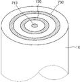
도 7은 일 실시예에 따른 본체의 일 단부를 도시한 도면이다.7 is a view showing one end of the body according to an embodiment.
도 7을 참조하면, 본체(10)에서 히터 모듈(예를 들어, 도 1, 도 5 또는 도 6의 히터 모듈(20))과 결합되는 단부가 도시되어 있다.Referring to FIG. 7 , an end coupled to the heater module (eg, the
본체(10)는 히터 모듈과 결합되는 단부에 동심을 갖는 복수의 원형상 또는 원형 밴드 형상의 전도성 부분들(710, 720 및 730)을 포함할 수 있다. 예를 들어, 제1 전도성 부분(710)은 원형상으로서, 접지 단자에 대응될 수 있다. 제2 전도성 부분(720)은 제1 전도성 부분(710)과 동심을 갖는 원형 밴드 형상으로서, (+) 단자에 대응할 수 있다. 제1 전도성 부분(710) 및 제2 전도성 부분(720)은 히터 모듈의 제1 커넥터 단자 쌍과 전기적인 연결을 형성할 수 있고, 이에 따라, 본체(10) 내부의 배터리와 히터 모듈 내부의 히터가 전기적으로 연결될 수 있다.The
한편, 제3 전도성 부분(730)은 제1 전도성 부분(710) 및 제2 전도성 부분(720)과 동심을 갖는 원형 밴드 형상으로서, 또 다른 (+) 단자에 대응할 수 있다. 제3 전도성 부분(730) 및 제1 전도성 부분(720)은 히터 모듈의 제2 커넥터 단자 쌍과 전기적인 연결을 형성할 수 있고, 이에 따라, 본체(10) 내부의 프로세서와 히터 모듈 내부의 집적 회로가 전기적으로 연결될 수 있다. 한편, 전도성 부분들(710, 720 및 730)은 동심을 갖는 복수의 원형상 또는 원형 밴드 형상을 가지므로, 히터 모듈이 본체(10)와 결합되는 배향에 상관없이 히터 모듈 상의 적어도 둘 이상의 커넥터 단자들과 전기적인 연결을 형성할 수 있다. 여기서 배향이란 본체와 결합되는 히터 모듈의 단부의 방향을 의미하는 것이 아니라, 히터 모듈의 길이 방향을 축으로 히터 모듈이 회전하는 정도를 의미할 수 있다.Meanwhile, the third
다만, 전술한 전도성 부분들(710, 720 및 730)의 개수, 배치, 단자의 종류 등은 모두 예시에 불과하다. 전도성 부분들(710, 720 및 730)의 개수, 배치, 단자의 종류 등은 히터 모듈의 적어도 하나의 커넥터 단자들의 구성에 대응되도록 적절하게 결정될 수 있다. 예를 들어, 제3 전도성 부분(730)은 (+) 단자가 아닐 수 있으며, 제1 전도성 부분(710)가 쌍을 이루지 않을 수 있다. 제3 전도성 부분(730)은 싱글 와이어 방식을 따를 수 있으며, 히터 모듈의 단일 커넥터 단자와 연결될 수도 있다.However, the number, arrangement, and types of terminals of the aforementioned
일 실시예는 컴퓨터에 의해 실행되는 프로그램 모듈과 같은 컴퓨터에 의해 실행가능한 명령어를 포함하는 기록 매체의 형태로도 구현될 수 있다. 컴퓨터 판독 가능 매체는 컴퓨터에 의해 액세스될 수 있는 임의의 가용 매체일 수 있고, 휘발성 및 비휘발성 매체, 분리형 및 비분리형 매체를 모두 포함한다. 또한, 컴퓨터 판독가능 매체는 컴퓨터 저장 매체 및 통신 매체를 모두 포함할 수 있다. 컴퓨터 저장 매체는 컴퓨터 판독가능 명령어, 데이터 구조, 프로그램 모듈 또는 기타 데이터와 같은 정보의 저장을 위한 임의의 방법 또는 기술로 구현된 휘발성 및 비휘발성, 분리형 및 비분리형 매체를 모두 포함한다. 통신 매체는 전형적으로 컴퓨터 판독가능 명령어, 데이터 구조, 프로그램 모듈과 같은 변조된 데이터 신호의 기타 데이터, 또는 기타 전송 메커니즘을 포함하며, 임의의 정보 전달 매체를 포함한다.An embodiment may also be implemented in the form of a recording medium including instructions executable by a computer, such as a program module executed by a computer. Computer-readable media can be any available media that can be accessed by a computer and includes both volatile and nonvolatile media, removable and non-removable media. In addition, computer-readable media may include both computer storage media and communication media. Computer storage media includes both volatile and nonvolatile, removable and non-removable media implemented in any method or technology for storage of information such as computer readable instructions, data structures, program modules or other data. Communication media typically includes computer readable instructions, data structures, other data in modulated data signals, such as program modules, or other transport mechanisms, and includes any information delivery media.
상술한 실시예들에 대한 설명은 예시적인 것에 불과하며, 당해 기술 분야에서 통상의 지식을 가진 자라면 이로부터 다양한 변형 및 균등한 다른 실시예가 가능하다는 점을 이해할 것이다. 따라서 발명의 진정한 보호 범위는 첨부된 청구범위에 의해 정해져야 할 것이며, 청구범위에 기재된 내용과 동등한 범위에 있는 모든 차이점은 청구범위에 의해 정해지는 보호 범위에 포함되는 것으로 해석되어야 할 것이다.The description of the above-described embodiments is merely exemplary, and it will be understood by those skilled in the art that various modifications and equivalent other embodiments are possible therefrom. Accordingly, the true scope of protection of the invention should be defined by the appended claims, and all differences within the scope of equivalents to those described in the claims should be construed as being included in the scope of protection defined by the claims.
1: 에어로졸 생성 장치 630: 실리카 위크
10: 본체 640: 코일 히터
20: 히터 모듈 710: 제1 전도성 부분
30: 카트리지 720: 제2 전도성 부분
110: 프로세서 730: 제3 전도성 부분
120: 배터리
130: 히터
140: 집적 회로
510: 액체 저장부
520: 펠트
530a: 제1 커넥터 단자
530b: 제2 커넥터 단자
540: FPCB
550: 내부 하우징
560: 기류 경로
610: 액체 저장부
620: 펠트1: aerosol generating device 630: silica wick
10: body 640: coil heater
20: heater module 710: first conductive portion
30: cartridge 720: second conductive portion
110: processor 730: third conductive portion
120: battery
130: heater
140: integrated circuit
510: liquid storage unit
520: felt
530a: first connector terminal
530b: second connector terminal
540: FPCB
550: inner housing
560: airflow path
610: liquid storage unit
620: felt
Claims (12)
프로세서 및 배터리를 포함하는 본체;
상기 본체와 착탈 가능하게 결합되고, 에어로졸 생성 물질을 가열하기 위한 히터를 포함하는 히터 모듈; 및
상기 히터 모듈과 착탈 가능하게 결합되고, 상기 히터로 전달될 상기 에어로졸 생성 물질을 보유하는 카트리지를 포함하고,
상기 히터 모듈은 상기 히터 모듈이 상기 본체와 결합되는 경우 상기 프로세서와 전기적으로 연결되는 집적 회로를 포함하고,
상기 집적 회로는,
상기 프로세서에 의해 사용자의 흡연과 연관된 동작이 감지될 때마다 상기 프로세서로부터 전달되는 신호에 기초하여 카운팅을 수행하고, 상기 카운팅의 결과에 대응되는 횟수를 저장하며,
상기 횟수는 상기 카트리지와 상이한 주기로 교체되는 상기 히터 모듈의 교체 시기를 판단하는데 이용되는, 에어로졸 생성 장치.An aerosol generating device comprising:
a body including a processor and a battery;
a heater module detachably coupled to the body and including a heater for heating the aerosol-generating material; and
a cartridge removably coupled to the heater module and holding the aerosol generating material to be delivered to the heater;
The heater module includes an integrated circuit electrically connected to the processor when the heater module is coupled to the body,
the integrated circuit,
Whenever a user's smoking-related motion is detected by the processor, counting is performed based on a signal transmitted from the processor, and the number of times corresponding to the result of the counting is stored,
The number of times is used to determine the replacement timing of the heater module to be replaced with a different cycle than the cartridge, an aerosol generating device.
상기 프로세서는,
상기 집적 회로로부터 식별 정보를 수신하고, 상기 수신된 식별 정보에 기초하여 상기 히터 모듈에 대한 정품 인증을 수행하는, 에어로졸 생성 장치. The method of claim 1,
The processor is
Receive identification information from the integrated circuit, and perform activation of the heater module based on the received identification information, an aerosol generating device.
상기 집적 회로는,
상기 횟수를 저장하기 위한 비휘발성 메모리를 포함하는, 에어로졸 생성 장치.The method of claim 1,
the integrated circuit,
and a non-volatile memory for storing the number of times.
상기 프로세서는,
상기 집적 회로에 저장된 횟수가 임계값 이상인 경우 상기 배터리와 상기 히터 간의 전기적인 연결을 차단하는, 에어로졸 생성 장치.The method of claim 1,
The processor is
When the number of times stored in the integrated circuit is greater than or equal to a threshold value, the aerosol generating device is to cut off the electrical connection between the battery and the heater.
상기 집적 회로는,
상기 저장된 횟수가 임계값 미만인 경우 제1 값을 출력하고, 상기 저장된 횟수가 상기 임계값 이상인 경우 제2 값을 출력하며,
상기 프로세서는,
상기 집적 회로로부터 출력되는 값이 상기 제1 값인 경우 상기 배터리와 상기 히터 간의 전기적인 연결을 허용하고, 상기 집적 회로로부터 출력되는 값이 상기 제2 값인 경우 상기 배터리와 상기 히터 간의 전기적인 연결을 차단하는, 에어로졸 생성 장치.The method of claim 1,
the integrated circuit,
outputting a first value when the number of times stored is less than a threshold value, and outputting a second value when the number of times stored is greater than or equal to the threshold value;
The processor is
When the value output from the integrated circuit is the first value, an electrical connection between the battery and the heater is allowed, and when the value output from the integrated circuit is the second value, the electrical connection between the battery and the heater is cut off which, an aerosol-generating device.
상기 집적 회로는 상기 히터 모듈 내에서 적어도 하나의 하우징에 의해 상기 히터와 분리된 공간에 배치되는, 에어로졸 생성 장치.The method of claim 1,
wherein the integrated circuit is disposed within the heater module in a space separated from the heater by at least one housing.
상기 카트리지는,
상기 에어로졸 생성 물질을 보유하는 액체 저장부; 및
상기 카트리지가 상기 히터 모듈과 결합되는 경우 상기 히터 모듈과 접촉하는 단부에 배치되는 펠트(felt)를 포함하고,
상기 히터는 상기 액체 저장부로부터 상기 펠트를 통해 전달되는 상기 에어로졸 생성 물질을 가열하는, 에어로졸 생성 장치.The method of claim 1,
The cartridge is
a liquid reservoir holding the aerosol generating material; and
When the cartridge is combined with the heater module comprising a felt (felt) disposed at the end in contact with the heater module,
wherein the heater heats the aerosol generating material delivered from the liquid reservoir through the felt.
상기 히터는 실리카 위크(wick)와 결합된 코일 히터 및 다공성 세라믹 히터 중 적어도 하나를 포함하는, 에어로졸 생성 장치.The method of claim 1,
wherein the heater comprises at least one of a coil heater associated with a silica wick and a porous ceramic heater.
상기 히터 모듈은,
상기 배터리와 상기 히터 간의 전기적인 연결 및 상기 프로세서와 상기 집적 회로 간의 전기적인 연결을 형성하기 위한 적어도 둘 이상의 커넥터 단자들을 포함하는, 에어로졸 생성 장치.The method of claim 1,
The heater module is
at least two or more connector terminals for forming an electrical connection between the battery and the heater and an electrical connection between the processor and the integrated circuit.
상기 집적 회로는 상기 히터 모듈의 외면의 적어도 일부를 따라 연장되는 FPCB(Flexible Printed Circuit Board)를 통해 상기 적어도 둘 이상의 커넥터 단자들 중 하나 이상과 연결되는, 에어로졸 생성 장치.11. The method of claim 10,
The integrated circuit is connected to one or more of the at least two or more connector terminals through a flexible printed circuit board (FPCB) extending along at least a portion of an outer surface of the heater module.
상기 본체는 상기 히터 모듈과 결합되는 단부에 동심을 갖는 복수의 원형상 또는 원형 밴드 형상의 전도성 부분들을 포함하고,
상기 전도성 부분들은 상기 히터 모듈이 상기 본체와 결합되는 배향에 상관없이 상기 적어도 둘 이상의 커넥터 단자들과 전기적인 연결을 형성하는, 에어로졸 생성 장치.11. The method of claim 10,
The main body includes a plurality of circular or circular band-shaped conductive parts having a concentricity at an end coupled to the heater module,
wherein the conductive portions form an electrical connection with the at least two or more connector terminals irrespective of the orientation in which the heater module is coupled to the body.
Priority Applications (6)
| Application Number | Priority Date | Filing Date | Title |
|---|---|---|---|
| KR1020200039430A KR102428411B1 (en) | 2020-03-31 | 2020-03-31 | Aerosol generating device including deteachable heater module |
| CN202080007241.2A CN113766845B (en) | 2020-03-31 | 2020-12-15 | Aerosol generating device including removable heater module |
| US17/294,602 US12075832B2 (en) | 2020-03-31 | 2020-12-15 | Aerosol generating device including detachable heater module |
| EP20886207.8A EP3908136A4 (en) | 2020-03-31 | 2020-12-15 | AEROSOL GENERATING DEVICE INCLUDING A DETACHABLE HEATER MODULE |
| PCT/KR2020/018305 WO2021201377A1 (en) | 2020-03-31 | 2020-12-15 | Aerosol generating device including detachable heater module |
| JP2021540223A JP7250142B2 (en) | 2020-03-31 | 2020-12-15 | Aerosol generator including detachable heater module |
Applications Claiming Priority (1)
| Application Number | Priority Date | Filing Date | Title |
|---|---|---|---|
| KR1020200039430A KR102428411B1 (en) | 2020-03-31 | 2020-03-31 | Aerosol generating device including deteachable heater module |
Publications (2)
| Publication Number | Publication Date |
|---|---|
| KR20210121947A KR20210121947A (en) | 2021-10-08 |
| KR102428411B1 true KR102428411B1 (en) | 2022-08-02 |
Family
ID=76283520
Family Applications (1)
| Application Number | Title | Priority Date | Filing Date |
|---|---|---|---|
| KR1020200039430A Active KR102428411B1 (en) | 2020-03-31 | 2020-03-31 | Aerosol generating device including deteachable heater module |
Country Status (6)
| Country | Link |
|---|---|
| US (1) | US12075832B2 (en) |
| EP (1) | EP3908136A4 (en) |
| JP (1) | JP7250142B2 (en) |
| KR (1) | KR102428411B1 (en) |
| CN (1) | CN113766845B (en) |
| WO (1) | WO2021201377A1 (en) |
Families Citing this family (15)
| Publication number | Priority date | Publication date | Assignee | Title |
|---|---|---|---|---|
| JP7438994B2 (en) * | 2021-01-07 | 2024-02-27 | 株式会社東芝 | Neural network device and learning method |
| JP7703783B2 (en) * | 2021-10-19 | 2025-07-07 | ケーティー アンド ジー コーポレイション | Aerosol Generator |
| JP7756247B2 (en) * | 2021-10-19 | 2025-10-17 | ケーティー アンド ジー コーポレイション | Aerosol generating device and method of operation thereof |
| CN114365871B (en) * | 2022-01-27 | 2025-06-20 | 惠州市新泓威科技有限公司 | Anti-counterfeiting electronic cigarette with limited service life and control method thereof |
| JP2025523662A (en) * | 2022-07-15 | 2025-07-23 | フィリップ・モーリス・プロダクツ・ソシエテ・アノニム | Modular aerosol generator |
| WO2024025369A1 (en) * | 2022-07-28 | 2024-02-01 | Kt&G Corporation | Aerosol generating device including heater module |
| JP2025522427A (en) * | 2022-07-28 | 2025-07-15 | ケーティー アンド ジー コーポレイション | Aerosol generating device including a heater module |
| KR102914605B1 (en) * | 2022-07-28 | 2026-01-19 | 주식회사 케이티앤지 | Aerosol generating device including heater module |
| JP7693935B2 (en) * | 2022-08-18 | 2025-06-17 | ケーティー アンド ジー コーポレイション | Aerosol Generator |
| KR102914606B1 (en) * | 2022-08-18 | 2026-01-19 | 주식회사 케이티앤지 | Aerosol generating device |
| EP4618790A4 (en) * | 2022-11-14 | 2026-03-04 | Kt & G Corp | HEATING DEVICE MODULE FOR AEROSOL GENERATOR AND AEROSOL GENERATOR INCLUDING IT |
| JP2026502200A (en) * | 2023-02-23 | 2026-01-21 | ケーティー アンド ジー コーポレイション | Aerosol Generator |
| JP2026505529A (en) * | 2023-04-06 | 2026-02-13 | ケーティー アンド ジー コーポレイション | Heater module for aerosol generating device, cartridge for aerosol generating device, and aerosol generating device |
| JPWO2025004180A1 (en) * | 2023-06-27 | 2025-01-02 | ||
| WO2025028949A1 (en) * | 2023-07-31 | 2025-02-06 | 주식회사 케이티앤지 | Aerosol-generating device |
Citations (5)
| Publication number | Priority date | Publication date | Assignee | Title |
|---|---|---|---|---|
| WO2014058678A1 (en) * | 2012-10-08 | 2014-04-17 | R. J. Reynolds Tobacco Company | An electronic smoking article and associated method |
| US20160206003A1 (en) | 2013-09-30 | 2016-07-21 | Japan Tobacco Inc. | Non-burning type flavor inhaler |
| WO2018055558A1 (en) * | 2016-09-23 | 2018-03-29 | Rai Strategic Holdings, Inc. | An aerosol delivery device with replaceable wick and heater assembly |
| WO2018114312A1 (en) | 2016-12-19 | 2018-06-28 | Philip Morris Products S.A. | Aerosol-generating system comprising multiple aerosol-forming substrates and a liquid transfer element |
| WO2018114263A1 (en) | 2016-12-19 | 2018-06-28 | Philip Morris Products S.A. | Aerosol-generating system having a cartridge with a side aperture |
Family Cites Families (17)
| Publication number | Priority date | Publication date | Assignee | Title |
|---|---|---|---|---|
| CN104026742A (en) * | 2013-03-05 | 2014-09-10 | 向智勇 | Heating control method and device for electronic cigarette |
| US10555556B2 (en) * | 2014-02-10 | 2020-02-11 | Philip Morris Products S.A. | Cartridge for an aerosol-generating system |
| HK1226257A1 (en) | 2014-02-10 | 2017-09-29 | Philip Morris Products S.A. | An aerosol-generating system comprising a device and a cartridge, in which the device ensures electrical contact with the cartridge |
| WO2016082077A1 (en) | 2014-11-24 | 2016-06-02 | 惠州市吉瑞科技有限公司 | Atomizer component, electronic cigarette having limited lifespan, and method for limiting lifespan of electronic cigarette |
| RU2723825C2 (en) * | 2016-03-31 | 2020-06-17 | Филип Моррис Продактс С.А. | Air flow in aerosol-generating system with mouthpiece |
| KR20240126878A (en) * | 2016-07-25 | 2024-08-21 | 필립모리스 프로덕츠 에스.에이. | Heater management |
| UA126477C2 (en) * | 2017-03-30 | 2022-10-12 | Кт & Г Корпорейшон | DEVICE FOR GENERATING AEROSOL AND A CRADLE CAPABLE OF RECEIVING IT |
| JP6974822B2 (en) * | 2017-04-11 | 2021-12-01 | 暮らし創研株式会社 | Smoking equipment |
| EP3610747A4 (en) * | 2017-04-11 | 2021-04-14 | KT & G Coporation | Aerosol generating device and method for providing adaptive feedback through puff recognition |
| KR102216139B1 (en) * | 2017-04-28 | 2021-02-16 | 주식회사 케이티앤지 | Method and apparatus for generating aerosols |
| US10842197B2 (en) | 2017-07-12 | 2020-11-24 | Rai Strategic Holdings, Inc. | Detachable container for aerosol delivery having pierceable membrane |
| GB201720338D0 (en) * | 2017-12-06 | 2018-01-17 | British American Tobacco Investments Ltd | Component for an aerosol-generating apparatus |
| CN109892699B (en) * | 2017-12-08 | 2022-04-15 | 深圳市赛尔美电子科技有限公司 | Electronic cigarette smoking frequency counting method, electronic cigarette, storage medium and equipment |
| WO2019113836A1 (en) * | 2017-12-13 | 2019-06-20 | 惠州市吉瑞科技有限公司深圳分公司 | Aerosol generation device and control method therefor, and microprocessor for aerosol generation device |
| PY1919412A (en) * | 2018-03-14 | 2020-07-31 | Canopy Growth Corp | VAPING DEVICES INCLUDING CARTRIDGES, TABLETS, SENSORS AND CONTROLS FOR VAPING DEVICES AND METHODS OF MANUFACTURING AND USING THE SAME |
| GB201812060D0 (en) * | 2018-07-24 | 2018-09-05 | Nicoventures Trading Ltd | A control module for a modular aerosol generating device, a module for a modular aerosol generating device and a modular aerosol generating device |
| CN109452693A (en) * | 2018-12-15 | 2019-03-12 | 泉州市宇朔工业设计有限公司 | Heating module and electronic smoking set with the heating module |
-
2020
- 2020-03-31 KR KR1020200039430A patent/KR102428411B1/en active Active
- 2020-12-15 JP JP2021540223A patent/JP7250142B2/en active Active
- 2020-12-15 US US17/294,602 patent/US12075832B2/en active Active
- 2020-12-15 WO PCT/KR2020/018305 patent/WO2021201377A1/en not_active Ceased
- 2020-12-15 CN CN202080007241.2A patent/CN113766845B/en active Active
- 2020-12-15 EP EP20886207.8A patent/EP3908136A4/en active Pending
Patent Citations (5)
| Publication number | Priority date | Publication date | Assignee | Title |
|---|---|---|---|---|
| WO2014058678A1 (en) * | 2012-10-08 | 2014-04-17 | R. J. Reynolds Tobacco Company | An electronic smoking article and associated method |
| US20160206003A1 (en) | 2013-09-30 | 2016-07-21 | Japan Tobacco Inc. | Non-burning type flavor inhaler |
| WO2018055558A1 (en) * | 2016-09-23 | 2018-03-29 | Rai Strategic Holdings, Inc. | An aerosol delivery device with replaceable wick and heater assembly |
| WO2018114312A1 (en) | 2016-12-19 | 2018-06-28 | Philip Morris Products S.A. | Aerosol-generating system comprising multiple aerosol-forming substrates and a liquid transfer element |
| WO2018114263A1 (en) | 2016-12-19 | 2018-06-28 | Philip Morris Products S.A. | Aerosol-generating system having a cartridge with a side aperture |
Also Published As
| Publication number | Publication date |
|---|---|
| EP3908136A4 (en) | 2022-03-09 |
| CN113766845A (en) | 2021-12-07 |
| CN113766845B (en) | 2024-01-12 |
| US20220400757A1 (en) | 2022-12-22 |
| JP2022529864A (en) | 2022-06-27 |
| JP7250142B2 (en) | 2023-03-31 |
| WO2021201377A1 (en) | 2021-10-07 |
| EP3908136A1 (en) | 2021-11-17 |
| US12075832B2 (en) | 2024-09-03 |
| KR20210121947A (en) | 2021-10-08 |
Similar Documents
| Publication | Publication Date | Title |
|---|---|---|
| KR102428411B1 (en) | Aerosol generating device including deteachable heater module | |
| US12082620B2 (en) | Aerosol generating device and operation method thereof | |
| KR102432917B1 (en) | Aerosol generating device that activates heater by detecting user's contact and method for operating the same | |
| KR102329280B1 (en) | Apparatus and method for transmitting and receiving data with aerosol generating device | |
| KR102324197B1 (en) | Aerosol generating device | |
| EP4209138B1 (en) | Electronic smoking device and capsule system | |
| KR102608671B1 (en) | A control body that can be combined with a cartridge, a cartridge that can be combined with a control body, a method of operating the control body, and a method of operating the cartridge. | |
| US10687554B2 (en) | Connection device, cartridge and electronic vaping device | |
| KR102323511B1 (en) | Aerosol generating device and operation method thereof | |
| KR20220038028A (en) | Aerosol generating apparatus performing heating operation automatically | |
| EP3817586B1 (en) | Vaporizer and aerosol generating apparatus including the same | |
| KR102442184B1 (en) | Aerosol generating device comprising multi-stage heater | |
| US20220273042A1 (en) | Aerosol generating device and operation method thereof | |
| JP2021534729A (en) | Atomizer and cartridge containing it | |
| KR102270186B1 (en) | Aerosol generating device | |
| KR102663248B1 (en) | Aerosol generating apparatus determining abnormal operation | |
| KR102442048B1 (en) | Aerosol generating apparatus and method for controlling of aerosol generating apparatus | |
| KR102286582B1 (en) | Aerosol generating device and method for selectively using cigarette and cartridge | |
| KR102400049B1 (en) | Cartomizer and aerosol generating apparatus comprising thereof | |
| US20230144267A1 (en) | Aerosol generating device and method of operation thereof | |
| KR102771330B1 (en) | Aerosol generating device | |
| KR102286581B1 (en) | Converter for charging aerosol generating device, and system for charging the aerosol generating device | |
| KR102554954B1 (en) | Aerosol generating device |
Legal Events
| Date | Code | Title | Description |
|---|---|---|---|
| PA0109 | Patent application |
Patent event code: PA01091R01D Comment text: Patent Application Patent event date: 20200331 |
|
| PA0201 | Request for examination | ||
| PG1501 | Laying open of application | ||
| E902 | Notification of reason for refusal | ||
| PE0902 | Notice of grounds for rejection |
Comment text: Notification of reason for refusal Patent event date: 20211109 Patent event code: PE09021S01D |
|
| E701 | Decision to grant or registration of patent right | ||
| PE0701 | Decision of registration |
Patent event code: PE07011S01D Comment text: Decision to Grant Registration Patent event date: 20220504 |
|
| GRNT | Written decision to grant | ||
| PR0701 | Registration of establishment |
Comment text: Registration of Establishment Patent event date: 20220728 Patent event code: PR07011E01D |
|
| PR1002 | Payment of registration fee |
Payment date: 20220729 End annual number: 3 Start annual number: 1 |
|
| PG1601 | Publication of registration |