KR102402395B1 - Display panel with a built-in touch screen and touch display device - Google Patents
Display panel with a built-in touch screen and touch display device Download PDFInfo
- Publication number
- KR102402395B1 KR102402395B1 KR1020150149791A KR20150149791A KR102402395B1 KR 102402395 B1 KR102402395 B1 KR 102402395B1 KR 1020150149791 A KR1020150149791 A KR 1020150149791A KR 20150149791 A KR20150149791 A KR 20150149791A KR 102402395 B1 KR102402395 B1 KR 102402395B1
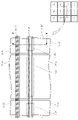
- Authority
- KR
- South Korea
- Prior art keywords
- touch electrode
- touch
- display panel
- electrode
- gate lines
- Prior art date
- Legal status (The legal status is an assumption and is not a legal conclusion. Google has not performed a legal analysis and makes no representation as to the accuracy of the status listed.)
- Active
Links
Images




Classifications
-
- G—PHYSICS
- G06—COMPUTING OR CALCULATING; COUNTING
- G06F—ELECTRIC DIGITAL DATA PROCESSING
- G06F3/00—Input arrangements for transferring data to be processed into a form capable of being handled by the computer; Output arrangements for transferring data from processing unit to output unit, e.g. interface arrangements
- G06F3/01—Input arrangements or combined input and output arrangements for interaction between user and computer
- G06F3/03—Arrangements for converting the position or the displacement of a member into a coded form
- G06F3/041—Digitisers, e.g. for touch screens or touch pads, characterised by the transducing means
-
- G—PHYSICS
- G06—COMPUTING OR CALCULATING; COUNTING
- G06F—ELECTRIC DIGITAL DATA PROCESSING
- G06F3/00—Input arrangements for transferring data to be processed into a form capable of being handled by the computer; Output arrangements for transferring data from processing unit to output unit, e.g. interface arrangements
- G06F3/01—Input arrangements or combined input and output arrangements for interaction between user and computer
- G06F3/03—Arrangements for converting the position or the displacement of a member into a coded form
- G06F3/041—Digitisers, e.g. for touch screens or touch pads, characterised by the transducing means
- G06F3/044—Digitisers, e.g. for touch screens or touch pads, characterised by the transducing means by capacitive means
- G06F3/0443—Digitisers, e.g. for touch screens or touch pads, characterised by the transducing means by capacitive means using a single layer of sensing electrodes
-
- G—PHYSICS
- G06—COMPUTING OR CALCULATING; COUNTING
- G06F—ELECTRIC DIGITAL DATA PROCESSING
- G06F3/00—Input arrangements for transferring data to be processed into a form capable of being handled by the computer; Output arrangements for transferring data from processing unit to output unit, e.g. interface arrangements
- G06F3/01—Input arrangements or combined input and output arrangements for interaction between user and computer
- G06F3/03—Arrangements for converting the position or the displacement of a member into a coded form
- G06F3/041—Digitisers, e.g. for touch screens or touch pads, characterised by the transducing means
- G06F3/0412—Digitisers structurally integrated in a display
-
- G—PHYSICS
- G06—COMPUTING OR CALCULATING; COUNTING
- G06F—ELECTRIC DIGITAL DATA PROCESSING
- G06F3/00—Input arrangements for transferring data to be processed into a form capable of being handled by the computer; Output arrangements for transferring data from processing unit to output unit, e.g. interface arrangements
- G06F3/01—Input arrangements or combined input and output arrangements for interaction between user and computer
- G06F3/03—Arrangements for converting the position or the displacement of a member into a coded form
- G06F3/041—Digitisers, e.g. for touch screens or touch pads, characterised by the transducing means
- G06F3/0416—Control or interface arrangements specially adapted for digitisers
-
- G—PHYSICS
- G06—COMPUTING OR CALCULATING; COUNTING
- G06F—ELECTRIC DIGITAL DATA PROCESSING
- G06F3/00—Input arrangements for transferring data to be processed into a form capable of being handled by the computer; Output arrangements for transferring data from processing unit to output unit, e.g. interface arrangements
- G06F3/01—Input arrangements or combined input and output arrangements for interaction between user and computer
- G06F3/03—Arrangements for converting the position or the displacement of a member into a coded form
- G06F3/041—Digitisers, e.g. for touch screens or touch pads, characterised by the transducing means
- G06F3/044—Digitisers, e.g. for touch screens or touch pads, characterised by the transducing means by capacitive means
-
- G—PHYSICS
- G06—COMPUTING OR CALCULATING; COUNTING
- G06F—ELECTRIC DIGITAL DATA PROCESSING
- G06F3/00—Input arrangements for transferring data to be processed into a form capable of being handled by the computer; Output arrangements for transferring data from processing unit to output unit, e.g. interface arrangements
- G06F3/01—Input arrangements or combined input and output arrangements for interaction between user and computer
- G06F3/03—Arrangements for converting the position or the displacement of a member into a coded form
- G06F3/041—Digitisers, e.g. for touch screens or touch pads, characterised by the transducing means
- G06F3/044—Digitisers, e.g. for touch screens or touch pads, characterised by the transducing means by capacitive means
- G06F3/0446—Digitisers, e.g. for touch screens or touch pads, characterised by the transducing means by capacitive means using a grid-like structure of electrodes in at least two directions, e.g. using row and column electrodes
-
- G—PHYSICS
- G06—COMPUTING OR CALCULATING; COUNTING
- G06F—ELECTRIC DIGITAL DATA PROCESSING
- G06F3/00—Input arrangements for transferring data to be processed into a form capable of being handled by the computer; Output arrangements for transferring data from processing unit to output unit, e.g. interface arrangements
- G06F3/01—Input arrangements or combined input and output arrangements for interaction between user and computer
- G06F3/03—Arrangements for converting the position or the displacement of a member into a coded form
- G06F3/041—Digitisers, e.g. for touch screens or touch pads, characterised by the transducing means
- G06F3/044—Digitisers, e.g. for touch screens or touch pads, characterised by the transducing means by capacitive means
- G06F3/0448—Details of the electrode shape, e.g. for enhancing the detection of touches, for generating specific electric field shapes, for enhancing display quality
-
- G—PHYSICS
- G09—EDUCATION; CRYPTOGRAPHY; DISPLAY; ADVERTISING; SEALS
- G09G—ARRANGEMENTS OR CIRCUITS FOR CONTROL OF INDICATING DEVICES USING STATIC MEANS TO PRESENT VARIABLE INFORMATION
- G09G3/00—Control arrangements or circuits, of interest only in connection with visual indicators other than cathode-ray tubes
- G09G3/20—Control arrangements or circuits, of interest only in connection with visual indicators other than cathode-ray tubes for presentation of an assembly of a number of characters, e.g. a page, by composing the assembly by combination of individual elements arranged in a matrix no fixed position being assigned to or needed to be assigned to the individual characters or partial characters
-
- G—PHYSICS
- G02—OPTICS
- G02F—OPTICAL DEVICES OR ARRANGEMENTS FOR THE CONTROL OF LIGHT BY MODIFICATION OF THE OPTICAL PROPERTIES OF THE MEDIA OF THE ELEMENTS INVOLVED THEREIN; NON-LINEAR OPTICS; FREQUENCY-CHANGING OF LIGHT; OPTICAL LOGIC ELEMENTS; OPTICAL ANALOGUE/DIGITAL CONVERTERS
- G02F1/00—Devices or arrangements for the control of the intensity, colour, phase, polarisation or direction of light arriving from an independent light source, e.g. switching, gating or modulating; Non-linear optics
- G02F1/01—Devices or arrangements for the control of the intensity, colour, phase, polarisation or direction of light arriving from an independent light source, e.g. switching, gating or modulating; Non-linear optics for the control of the intensity, phase, polarisation or colour
- G02F1/13—Devices or arrangements for the control of the intensity, colour, phase, polarisation or direction of light arriving from an independent light source, e.g. switching, gating or modulating; Non-linear optics for the control of the intensity, phase, polarisation or colour based on liquid crystals, e.g. single liquid crystal display cells
- G02F1/133—Constructional arrangements; Operation of liquid crystal cells; Circuit arrangements
- G02F1/1333—Constructional arrangements; Manufacturing methods
- G02F1/13338—Input devices, e.g. touch panels
-
- G—PHYSICS
- G06—COMPUTING OR CALCULATING; COUNTING
- G06F—ELECTRIC DIGITAL DATA PROCESSING
- G06F2203/00—Indexing scheme relating to G06F3/00 - G06F3/048
- G06F2203/041—Indexing scheme relating to G06F3/041 - G06F3/045
- G06F2203/04111—Cross over in capacitive digitiser, i.e. details of structures for connecting electrodes of the sensing pattern where the connections cross each other, e.g. bridge structures comprising an insulating layer, or vias through substrate
-
- G—PHYSICS
- G09—EDUCATION; CRYPTOGRAPHY; DISPLAY; ADVERTISING; SEALS
- G09G—ARRANGEMENTS OR CIRCUITS FOR CONTROL OF INDICATING DEVICES USING STATIC MEANS TO PRESENT VARIABLE INFORMATION
- G09G2300/00—Aspects of the constitution of display devices
- G09G2300/04—Structural and physical details of display devices
- G09G2300/0421—Structural details of the set of electrodes
- G09G2300/0426—Layout of electrodes and connections
-
- G—PHYSICS
- G09—EDUCATION; CRYPTOGRAPHY; DISPLAY; ADVERTISING; SEALS
- G09G—ARRANGEMENTS OR CIRCUITS FOR CONTROL OF INDICATING DEVICES USING STATIC MEANS TO PRESENT VARIABLE INFORMATION
- G09G2354/00—Aspects of interface with display user
Landscapes
- Engineering & Computer Science (AREA)
- Theoretical Computer Science (AREA)
- General Engineering & Computer Science (AREA)
- Physics & Mathematics (AREA)
- General Physics & Mathematics (AREA)
- Human Computer Interaction (AREA)
- Computer Hardware Design (AREA)
- Quality & Reliability (AREA)
- Devices For Indicating Variable Information By Combining Individual Elements (AREA)
- Position Input By Displaying (AREA)
Abstract
본 실시예들은, 터치스크린 내장형 디스플레이 패널 및 터치 디스플레이 디바이스에 관한 것으로서, 더욱 상세하게는, 터치 전극과 기생 캐패시턴스를 형성하는 게이트 라인이 특정 게이트 라인에 집중되지 않고 보다 많은 게이트 라인으로 분산될 수 있도록 해주는 터치전극 구조를 갖고, 이를 통해, 각 게이트 라인 간의 로드 편차를 줄여 주어 화상 품질을 향상시킬 수 있는 터치스크린 내장형 디스플레이 패널 및 터치 디스플레이 디바이스에 관한 것이다. The present embodiments relate to a touch screen-embedded display panel and a touch display device, and more particularly, so that a gate line forming a touch electrode and a parasitic capacitance can be distributed to more gate lines without being concentrated on a specific gate line. It relates to a touch screen-embedded display panel and a touch display device that have a touch electrode structure that allows the display to improve image quality by reducing load deviation between gate lines through this.
Description
본 실시예들은 터치스크린 내장형 디스플레이 패널 및 터치 디스플레이 디바이스에 관한 것이다. The present embodiments relate to a touch screen-embedded display panel and a touch display device.
정보화 사회가 발전함에 따라 화상을 표시하기 위한 디스플레이 디바이스에 대한 요구가 다양한 형태로 증가하고 있으며, 근래에는 액정표시장치(LCD: Liquid Crystal Display Device), 플라즈마 표시장치(PDP: Plasma Display Panel), 표시장치(OLED: Organic Light Emitting Display Device) 등과 같은 여러 가지 디스플레이 디바이스가 활용되고 있다. As the information society develops, the demand for display devices for displaying images is increasing in various forms, and in recent years, liquid crystal display (LCD), plasma display (PDP: plasma display panel), display Various display devices such as an organic light emitting display device (OLED) are being used.
이러한 디스플레이 디바이스는, 버튼, 키보드, 마우스 등의 통상적인 입력방식에서 탈피하여, 사용자가 손쉽게 정보 혹은 명령을 직관적이고 편리하게 입력할 수 있도록 해주는 터치 기반의 입력방식을 제공한다. Such a display device provides a touch-based input method that allows a user to easily and intuitively and conveniently input information or commands, breaking away from a conventional input method such as a button, a keyboard, and a mouse.
이러한 터치 기반의 입력 방식을 제공하기 위해서는, 사용자의 터치 유무를 파악하고 터치 좌표를 정확하게 검출할 수 있어야 한다. In order to provide such a touch-based input method, it is necessary to detect the presence or absence of a user's touch and to accurately detect the touch coordinates.
이를 위해, 터치스크린 패널에 형성된 다수의 터치 전극(예: 가로 방향 전극, 세로 방향 전극)을 통해 터치 전극 간의 캐패시턴스 또는 터치 전극과 손가락 등의 포인터 간의 캐패시턴스의 변화를 토대로 터치 유무 및 터치 좌표 등을 검출하는 캐패시턴스 터치 방식이 많이 채용되고 있다. To this end, based on the change in capacitance between the touch electrodes or the capacitance between the touch electrodes and a pointer such as a finger through a plurality of touch electrodes (eg, horizontal electrodes, vertical electrodes) formed on the touch screen panel, the presence or absence of touch and touch coordinates are determined. A capacitive touch method for detecting has been widely used.
한편, 터치 구동 및 센싱 시, 터치 센싱에 필요한 캐패시턴스 이외에, 불필요한 기생 캐패시턴스(Parasitic Capacitance)가 형성될 수 있다. Meanwhile, during touch driving and sensing, unnecessary parasitic capacitance may be formed in addition to the capacitance required for touch sensing.
이러한 불필요한 기생 캐패시턴스는 터치 전극과 게이트 라인 사이에도 형성될 수 있는데, 이 경우, 터치 전극 구조에 따라 기생 캐패시턴스가 형성되는 게이트 라인이 특정 게이트 라인에 집중될 수 있으며, 이러한 현상은 게이트 라인 간의 기생 캐피시턴스 편차를 발생시켜 게이트 라인 간의 로드 편차를 유발할 수 있다. Such unnecessary parasitic capacitance may also be formed between the touch electrode and the gate line. In this case, depending on the structure of the touch electrode, the gate line on which the parasitic capacitance is formed may be concentrated on a specific gate line, and this phenomenon is caused by the parasitic capacitance between the gate lines. By generating a capacitance deviation, a load deviation between the gate lines may be caused.
이러한 게이트 라인 간의 로드 편차는, 각 게이트 라인을 통해 공급되는 게이트 신호의 신호적인 특성 편차를 초래하여 화상 품질을 떨어뜨릴 수 있다. Such a load deviation between the gate lines may cause a signal characteristic deviation of a gate signal supplied through each gate line, thereby degrading image quality.
이러한 문제점은, 터치스크린 패널(TSP: Touch Screen Panel)이 디스플레이 패널에 내장되는 디스플레이 디바이스의 경우, 더욱 심각하게 발생할 수 있다. This problem may occur more seriously in the case of a display device in which a touch screen panel (TSP) is embedded in the display panel.
본 실시예들의 목적은, 터치 전극과 기생 캐패시턴스를 형성하는 게이트 라인이 특정 게이트 라인에 집중되지 않고 보다 많은 게이트 라인으로 분산될 수 있도록 해주는 터치전극 구조를 갖는 터치스크린 내장형 디스플레이 패널 및 터치 디스플레이 디바이스를 제공하는 데 있다. An object of the present embodiments is to provide a touch screen embedded display panel and a touch display device having a touch electrode structure that allows a touch electrode and a gate line forming a parasitic capacitance to be distributed to more gate lines without being concentrated on a specific gate line. is to provide
본 실시예들의 다른 목적은, 각 게이트 라인 간의 로드 편차를 줄일 수 있는 터치스크린 내장형 디스플레이 패널 및 터치 디스플레이 디바이스를 제공하는 데 있다. Another object of the present embodiments is to provide a touch screen-embedded display panel and a touch display device capable of reducing a load deviation between each gate line.
일 측면에서, 본 실시예들은, 제1방향으로 배치된 다수의 데이터 라인과, 제2방향으로 배치된 다수의 게이트 라인과, N(N≥2)행 M(M≥2)열로 배치된 다수의 터치 전극을 포함하는 터치스크린 내장형 디스플레이 패널을 제공할 수 있다. In one aspect, the present embodiments provide a plurality of data lines arranged in a first direction, a plurality of gate lines arranged in a second direction, and a plurality of N (N≥2) rows and M(M≥2) columns. It is possible to provide a touch screen built-in display panel including a touch electrode of.
이러한 터치스크린 내장형 디스플레이 패널은, N개의 터치 전극 행에서 n(1≤n≤N-1)번째의 터치 전극 행은 행 방향으로 인접한 제1 터치 전극과 제2 터치 전극을 포함하고, N개의 터치 전극 행에서 n+1(2≤n+1≤N)번째의 터치 전극 행은 행 방향으로 인접한 제3 터치 전극과 제4 터치 전극을 포함한다. In such a touch screen-embedded display panel, the n (1≤n≤N-1)-th touch electrode row in the N touch electrode rows includes first and second touch electrodes adjacent in the row direction, and the N touch electrodes An n+1 (2≤n+1≤N)-th touch electrode row in the electrode row includes a third touch electrode and a fourth touch electrode adjacent in the row direction.
제1 터치 전극 및 제3 터치 전극은 열 방향으로 인접하고, 제2 터치 전극및 제4 터치 전극은 열 방향으로 인접한다. The first touch electrode and the third touch electrode are adjacent in the column direction, and the second touch electrode and the fourth touch electrode are adjacent in the column direction.
이러한 터치스크린 내장형 디스플레이 패널에서, 제1 터치 전극 및 제3 터치 전극 간의 경계영역과, 제2 터치 전극 및 제4 터치 전극 간의 경계영역은, 서로 다른 직선 상에 배치될 수 있다. In such a touch screen-embedded display panel, a boundary area between the first and third touch electrodes and a boundary area between the second and fourth touch electrodes may be disposed on different straight lines.
이러한 터치스크린 내장형 디스플레이 패널에서, 각 터치 전극 행은 사선 방향으로 배치될 수 있다. In such a touch screen-embedded display panel, each row of touch electrodes may be disposed in an oblique direction.
다른 측면에서, 본 실시예들은, 다수의 데이터 라인 및 다수의 게이트 라인이 배치되며, 다수의 터치 전극이 N(N≥2)행 M(M≥2)열로 배치된 디스플레이 패널과, 다수의 터치 전극을 구동하여 터치를 센싱하는 터치 회로를 포함할 수 있다. In another aspect, the present embodiments include a display panel in which a plurality of data lines and a plurality of gate lines are disposed, and a plurality of touch electrodes are disposed in N (N≧2) rows and M (M≧2) columns, and a plurality of touch electrodes A touch circuit for sensing a touch by driving an electrode may be included.
이러한 터치 디스플레이 디바이스에서 디스플레이 패널은, n(1≤n≤N-1)번째의 터치 전극 행은 인접한 제1 터치 전극과 제2 터치 전극을 포함하고, n+1(2≤n+1≤N)번째의 터치 전극 행은 인접한 제3 터치 전극과 제4 터치 전극을 포함하며, 제1 터치 전극및 제3 터치 전극은 열 방향으로 인접하고, 제2 터치 전극 및 제4 터치 전극은 열 방향으로 인접하며, 제1 터치 전극 및 제3 터치 전극 간의 경계영역과, 제2 터치 전극 및 제4 터치 전극 간의 경계영역은, 서로 다른 직선 상에 배치될 수 있다. In such a touch display device, in the display panel, an n (1≤n≤N-1)-th touch electrode row includes adjacent first and second touch electrodes, and n+1 (2≤n+1≤N) )-th touch electrode row includes adjacent third and fourth touch electrodes, the first and third touch electrodes are adjacent to each other in a column direction, and the second and fourth touch electrodes are adjacent to each other in a column direction. Adjacent, a boundary area between the first and third touch electrodes and a boundary area between the second and fourth touch electrodes may be disposed on different straight lines.
또 다른 측면에서, 본 실시예들은, 제1방향으로 배치된 다수의 데이터 라인과, 제2방향으로 배치된 다수의 게이트 라인과, N(N≥2)행 M(M≥2)열로 배치된 다수의 터치 전극을 포함하는 터치스크린 내장형 디스플레이 패널을 제공할 수 있다. In another aspect, the present embodiments provide a plurality of data lines arranged in a first direction, a plurality of gate lines arranged in a second direction, and N (N≥2) rows and M(M≥2) columns. It is possible to provide a touch screen-embedded display panel including a plurality of touch electrodes.
이러한 터치스크린 내장형 디스플레이 패널에서, 각 터치 전극의 열 방향 에지 부분은 둘 이상의 단을 갖는 계단 형상으로 되어 있을 수 있다. In such a touch screen-embedded display panel, the edge portion in the column direction of each touch electrode may have a step shape having two or more steps.
이러한 터치스크린 내장형 디스플레이 패널에서, 각 터치 전극의 열 방향 에지 부분에서 둘 이상의 단은 둘 이상의 게이트 라인과 서로 대응되어 위치할 수 있다. In such a touch screen-embedded display panel, two or more stages in the column direction edge portion of each touch electrode may be positioned to correspond to two or more gate lines.
또 다른 측면에서, 본 실시예들은, 다수의 데이터 라인 및 다수의 게이트 라인이 배치되며, 다수의 터치 전극이 N(N≥2)행 M(M≥2)열로 배치된 디스플레이 패널과, 다수의 터치 전극을 구동하여 터치를 센싱하는 터치 회로를 포함하는 터치 디스플레이 디바이스를 제공할 수 있다. In another aspect, the present embodiments include a display panel in which a plurality of data lines and a plurality of gate lines are disposed, and a plurality of touch electrodes are disposed in N (N≧2) rows and M (M≧2) columns, and a plurality of A touch display device including a touch circuit for sensing a touch by driving a touch electrode may be provided.
이러한 터치 디스플레이 디바이스의 디스플레이 패널에서 각 터치 전극의 열 방향 에지 부분은 둘 이상의 단을 갖는 계단 형상으로 되어 있을 수 있다.In the display panel of such a touch display device, the edge portion in the column direction of each touch electrode may have a step shape having two or more steps.
이상에서 설명한 바와 같은 본 실시예들에 의하면, 터치 전극과 기생 캐패시턴스를 형성하는 게이트 라인이 특정 게이트 라인에 집중되지 않고 보다 많은 게이트 라인으로 분산될 수 있도록 해주는 터치전극 구조를 갖는 터치스크린 내장형 디스플레이 패널 및 터치 디스플레이 디바이스를 제공할 수 있다. According to the present embodiments as described above, a touch screen embedded display panel having a touch electrode structure that allows the touch electrode and the gate line forming the parasitic capacitance to be distributed to more gate lines without being concentrated on a specific gate line and a touch display device.
또한, 본 실시예들에 의하면, 각 게이트 라인 간의 로드 편차를 줄일 수 있는 터치스크린 내장형 디스플레이 패널 및 터치 디스플레이 디바이스를 제공할 수 있다.In addition, according to the present embodiments, it is possible to provide a touch screen-embedded display panel and a touch display device capable of reducing a load deviation between each gate line.
도 1은 본 실시예들에 따른 터치 디스플레이 디바이스의 시스템 구성도이다.
도 2 및 도 3은 본 실시예들에 따른 터치 디스플레이 디바이스에서, 제1타입의 터치 전극 구조를 나타낸 도면이다.
도 4는 본 실시예들에 따른 제1타입의 터치 전극 구조 하에서, 2개의 터치 전극이 열 방향으로 인접해 있는 영역에 대한 단면도이다.
도 5는 본 실시예들에 따른 제1타입의 터치 전극 구조 하에서, 열 방향으로 인접한 2개의 터치 전극이 주변의 게이트 라인들과 형성하는 기생 캐패시턴스들을 나타낸 단면도이다.
도 6 및 도 7은 본 실시예들에 따른 터치 디스플레이 디바이스에서, 제2타입의 터치 전극 구조를 나타낸 도면이다.
도 8은 본 실시예들에 따른 제2타입의 터치 전극 구조 하에서, 1번째 터치 전극 열에서 열 방향으로 인접한 2개의 터치 전극이 주변의 게이트 라인들과 형성하는 기생 캐패시턴스들을 나타낸 단면도이다.
도 9는 본 실시예들에 따른 제2타입의 터치 전극 구조 하에서, 2번째 터치 전극 열에서 열 방향으로 인접한 2개의 터치 전극이 주변의 게이트 라인들과 형성하는 기생 캐패시턴스들을 나타낸 단면도이다.
도 10은 본 실시예들에 따른 제2타입의 터치 전극 구조 하에서, 3번째 터치 전극 열에서 열 방향으로 인접한 2개의 터치 전극이 주변의 게이트 라인들과 형성하는 기생 캐패시턴스들을 나타낸 단면도이다.
도 11 및 도 12은 본 실시예들에 따른 터치 디스플레이 디바이스에서, 제3타입의 터치 전극 구조를 나타낸 도면이다.
도 13은 본 실시예들에 따른 제3타입의 터치 전극 구조 하에서, 열 방향으로 인접한 2개의 터치 전극이 주변의 게이트 라인들과 형성하는 기생 캐패시턴스들을 나타낸 단면도이다.1 is a system configuration diagram of a touch display device according to the present embodiments.
2 and 3 are diagrams illustrating a structure of a first type of touch electrode in the touch display device according to the present embodiments.
4 is a cross-sectional view of a region in which two touch electrodes are adjacent in a column direction under the first type of touch electrode structure according to the present embodiments.
5 is a cross-sectional view illustrating parasitic capacitances formed by two touch electrodes adjacent in a column direction with surrounding gate lines under the first type of touch electrode structure according to the present embodiments.
6 and 7 are diagrams illustrating a structure of a second type of touch electrode in the touch display device according to the present embodiments.
FIG. 8 is a cross-sectional view illustrating parasitic capacitances formed by two touch electrodes adjacent in a column direction in a first touch electrode column with surrounding gate lines under the second type of touch electrode structure according to the present embodiments.
9 is a cross-sectional view illustrating parasitic capacitances formed by two touch electrodes adjacent in a column direction in a second touch electrode column with surrounding gate lines under the second type of touch electrode structure according to the present embodiments.
10 is a cross-sectional view illustrating parasitic capacitances formed by two touch electrodes adjacent in a column direction in a third touch electrode column with surrounding gate lines under the structure of the second type of touch electrode according to the present embodiments.
11 and 12 are diagrams illustrating a structure of a third type of touch electrode in the touch display device according to the present embodiments.
13 is a cross-sectional view illustrating parasitic capacitances formed by two touch electrodes adjacent in a column direction with neighboring gate lines under the third type of touch electrode structure according to the present embodiments.
이하, 본 발명의 일부 실시예들을 예시적인 도면을 참조하여 상세하게 설명한다. 각 도면의 구성요소들에 참조부호를 부가함에 있어서, 동일한 구성요소들에 대해서는 비록 다른 도면상에 표시되더라도 가능한 한 동일한 부호를 가질 수 있다. 또한, 본 발명을 설명함에 있어, 관련된 공지 구성 또는 기능에 대한 구체적인 설명이 본 발명의 요지를 흐릴 수 있다고 판단되는 경우에는 그 상세한 설명은 생략할 수 있다.Hereinafter, some embodiments of the present invention will be described in detail with reference to exemplary drawings. In adding reference numerals to components of each drawing, the same components may have the same reference numerals as much as possible even though they are indicated in different drawings. In addition, in describing the present invention, if it is determined that a detailed description of a related known configuration or function may obscure the gist of the present invention, the detailed description may be omitted.
또한, 본 발명의 구성 요소를 설명하는 데 있어서, 제 1, 제 2, A, B, (a), (b) 등의 용어를 사용할 수 있다. 이러한 용어는 그 구성 요소를 다른 구성 요소와 구별하기 위한 것일 뿐, 그 용어에 의해 해당 구성 요소의 본질, 차례, 순서 또는 개수 등이 한정되지 않는다. 어떤 구성 요소가 다른 구성요소에 "연결", "결합" 또는 "접속"된다고 기재된 경우, 그 구성 요소는 그 다른 구성요소에 직접적으로 연결되거나 또는 접속될 수 있지만, 각 구성 요소 사이에 다른 구성 요소가 "개재"되거나, 각 구성 요소가 다른 구성 요소를 통해 "연결", "결합" 또는 "접속"될 수도 있다고 이해되어야 할 것이다.In addition, in describing the components of the present invention, terms such as first, second, A, B, (a), (b), etc. may be used. These terms are only for distinguishing the elements from other elements, and the essence, order, order, or number of the elements are not limited by the terms. When it is described that a component is “connected”, “coupled” or “connected” to another component, the component may be directly connected or connected to the other component, but other components may be interposed between each component. It should be understood that each component may be “interposed” or “connected”, “coupled” or “connected” through another component.
도 1은 본 실시예들에 따른 터치 디스플레이 디바이스(100)의 시스템 구성도이다. 1 is a system configuration diagram of a
도 1을 참조하면, 본 실시예들에 따른 터치 디스플레이 디바이스(100)는, 화상 표시 기능(디스플레이 기능)과 터치 센싱 기능을 제공할 수 있는 디바이스이다. Referring to FIG. 1 , a
이러한 본 실시예들에 따른 터치 디스플레이 디바이스(100)는, 일 예로, 터치 입력에 대한 터치 센싱 기능을 갖는 TV, 모니터 등의 중대형 디바이스이거나, 스마트 폰, 태블릿 등의 모바일 디바이스일 수도 있다. The
도 1을 참조하면, 본 실시예들에 따른 터치 디스플레이 디바이스(100)는, 디스플레이 기능을 제공하기 위하여, 디스플레이 패널(110), 데이터 드라이버(120), 게이트 드라이버(130) 및 컨트롤러(140) 등을 포함한다. Referring to FIG. 1 , the
디스플레이 패널(110)은, 제1방향(예: 열 방향)으로 배치된 다수의 데이터 라인(DL)과, 제2방향(예: 행 방향)으로 배치된 다수의 게이트 라인(GL)을 포함할 수 있다. The display panel 110 may include a plurality of data lines DL arranged in a first direction (eg, a column direction) and a plurality of gate lines GL arranged in a second direction (eg, a row direction). can
데이터 드라이버(120)는 다수의 데이터 라인(DL)을 구동한다. The
게이트 드라이버(130)는 다수의 게이트 라인(GL)을 구동한다. The
컨트롤러(140)는 데이터 드라이버(120) 및 게이트 드라이버(130)를 제어하는데, 이를 위해, 데이터 드라이버(120) 및 게이트 드라이버(130)로 각종 제어신호를 공급한다. The
이러한 컨트롤러(140)는, 각 프레임에서 구현하는 타이밍에 따라 스캔을 시작하고, 외부에서 입력되는 입력 영상 데이터를 데이터 드라이버(120)에서 사용하는 데이터 신호 형식에 맞게 전환하여 전환된 영상 데이터를 출력하고, 스캔에 맞춰 적당한 시간에 데이터 구동을 통제한다. The
이러한 컨트롤러(140)는 통상의 디스플레이 기술에서 이용되는 타이밍 컨트롤러(Timing Controller)이거나, 타이밍 컨트롤러(Timing Controller)를 포함하여 다른 제어 기능도 더 수행하는 제어장치일 수 있다. The
데이터 드라이버(120)는, 다수의 데이터 라인(DL)으로 데이터 전압을 공급함으로써, 다수의 데이터 라인(DL)을 구동한다. 여기서, 데이터 드라이버(120)는 '소스 드라이버'라고도 한다. The
게이트 드라이버(130)는, 다수의 게이트 라인(GL)으로 스캔 신호를 순차적으로 공급함으로써, 다수의 게이트 라인(GL)을 순차적으로 구동한다. 여기서, 게이트 드라이버(130)는 '스캔 드라이버'라고도 한다. The
게이트 드라이버(130)는, 컨트롤러(140)의 제어에 따라, 온(On) 전압 또는 오프(Off) 전압의 스캔 신호를 다수의 게이트 라인(GL)으로 순차적으로 공급한다. The
데이터 드라이버(120)는, 게이트 드라이버(130)에 의해 특정 게이트 라인이 열리면, 컨트롤러(140)로부터 수신한 영상 데이터를 아날로그 형태의 데이터 전압으로 변환하여 다수의 데이터 라인(DL)으로 공급한다. When a specific gate line is opened by the
데이터 드라이버(120)는, 도 1에서는 디스플레이 패널(110)의 일측(예: 상측 또는 하측)에만 위치하고 있으나, 구동 방식, 패널 설계 방식 등에 따라서, 디스플레이 패널(110)의 양측(예: 상측과 하측)에 모두 위치할 수도 있다. Although the
게이트 드라이버(130)는, 도 1에서는 디스플레이 패널(110)의 일 측(예: 좌측 또는 우측)에만 위치하고 있으나, 구동 방식, 패널 설계 방식 등에 따라서, 디스플레이 패널(110)의 양측(예: 좌측과 우측)에 모두 위치할 수도 있다. Although the
전술한 컨트롤러(140)는, 입력 영상 데이터와 함께, 수직 동기 신호(Vsync), 수평 동기 신호(Hsync), 입력 데이터 인에이블(DE: Data Enable) 신호, 클럭 신호(CLK) 등을 포함하는 각종 타이밍 신호들을 외부(예: 호스트 시스템)로부터 수신한다. The above-described
컨트롤러(140)는, 외부로부터 입력된 입력 영상 데이터를 데이터 드라이버(120)에서 사용하는 데이터 신호 형식에 맞게 전환하여 전환된 영상 데이터를 출력하는 것 이외에, 데이터 드라이버(120) 및 게이트 드라이버(130)를 제어하기 위하여, 수직 동기 신호(Vsync), 수평 동기 신호(Hsync), 입력 DE 신호, 클럭 신호 등의 타이밍 신호를 입력 받아, 각종 제어 신호들을 생성하여 데이터 드라이버(120) 및 게이트 드라이버(130)로 출력한다. The
예를 들어, 컨트롤러(140)는, 게이트 드라이버(130)를 제어하기 위하여, 게이트 스타트 펄스(GSP: Gate Start Pulse), 게이트 쉬프트 클럭(GSC: Gate Shift Clock), 게이트 출력 인에이블 신호(GOE: Gate Output Enable) 등을 포함하는 각종 게이트 제어 신호(GCS: Gate Control Signal)를 출력한다. For example, in order to control the
여기서, 게이트 스타트 펄스(GSP)는 게이트 드라이버(130)를 구성하는 하나 이상의 게이트 드라이버 집적회로의 동작 스타트 타이밍을 제어한다. 게이트 쉬프트 클럭(GSC)은 하나 이상의 게이트 드라이버 집적회로에 공통으로 입력되는 클럭 신호로서, 스캔 신호(게이트 펄스)의 쉬프트 타이밍을 제어한다. 게이트 출력 인에이블 신호(GOE)는 하나 이상의 게이트 드라이버 집적회로의 타이밍 정보를 지정하고 있다. Here, the gate start pulse GSP controls the operation start timing of one or more gate driver integrated circuits constituting the
또한, 컨트롤러(140)는, 데이터 드라이버(120)를 제어하기 위하여, 소스 스타트 펄스(SSP: Source Start Pulse), 소스 샘플링 클럭(SSC: Source Sampling Clock), 소스 출력 인에이블 신호(SOE: Source Output Enable) 등을 포함하는 각종 데이터 제어 신호(DCS: Data Control Signal)를 출력한다. In addition, the
여기서, 소스 스타트 펄스(SSP)는 데이터 드라이버(120)를 구성하는 하나 이상의 소스 드라이버 집적회로의 데이터 샘플링 시작 타이밍을 제어한다. 소스 샘플링 클럭(SSC)은 소스 드라이버 집적회로 각각에서 데이터의 샘플링 타이밍을 제어하는 클럭 신호이다. 소스 출력 인에이블 신호(SOE)는 데이터 드라이버(120)의 출력 타이밍을 제어한다. Here, the source start pulse SSP controls the data sampling start timing of one or more source driver integrated circuits constituting the
데이터 드라이버(120)는, 적어도 하나의 소스 드라이버 집적회로(Source Driver Integrated Circuit)를 포함하여 다수의 데이터 라인을 구동할 수 있다. The
각 소스 드라이버 집적회로는, 테이프 오토메티드 본딩(TAB: Tape Automated Bonding) 방식 또는 칩 온 글래스(COG: Chip On Glass) 방식으로 디스플레이 패널(110)의 본딩 패드(Bonding Pad)에 연결되거나, 디스플레이 패널(110)에 직접 배치될 수도 있으며, 경우에 따라서, 디스플레이 패널(110)에 집적화되어 배치될 수도 있다. 또한, 각 소스 드라이버 집적회로는, 디스플레이 패널(110)에 연결된 필름 상에 실장 되는 칩 온 필름(COF: Chip On Film) 방식으로 구현될 수도 있다. Each source driver integrated circuit is connected to a bonding pad of the display panel 110 by a tape automated bonding (TAB) method or a chip on glass (COG) method, or the display panel It may be directly disposed on the 110 , or may be integrated and disposed on the display panel 110 in some cases. In addition, each source driver integrated circuit may be implemented in a chip on film (COF) method mounted on a film connected to the display panel 110 .
각 소스 드라이버 집적회로는, 쉬프트 레지스터(Shift Register), 래치 회로(Latch Circuit), 디지털 아날로그 컨버터(DAC: Digital to Analog Converter), 출력 버퍼(Output Buffer) 등을 포함할 수 있다. Each source driver integrated circuit may include a shift register, a latch circuit, a digital to analog converter (DAC), an output buffer, and the like.
게이트 드라이버(130)는, 적어도 하나의 게이트 드라이버 집적회로(Gate Driver Integrated Circuit)를 포함할 수 있다. The
각 게이트 드라이버 집적회로는, 테이프 오토메티드 본딩(TAB) 방식 또는 칩 온 글래스(COG) 방식으로 디스플레이 패널(110)의 본딩 패드(Bonding Pad)에 연결되거나, GIP(Gate In Panel) 타입으로 구현되어 디스플레이 패널(110)에 직접 배치될 수도 있으며, 경우에 따라서, 디스플레이 패널(110)에 집적화되어 배치될 수도 있다. 또한, 각 게이트 드라이버 집적회로는 디스플레이 패널(110)과 연결된 필름 상에 실장 되는 칩 온 필름(COF) 방식으로 구현될 수도 있다. Each gate driver integrated circuit is connected to a bonding pad of the display panel 110 by a tape automated bonding (TAB) method or a chip-on-glass (COG) method, or is implemented as a GIP (Gate In Panel) type. It may be directly disposed on the display panel 110 , or may be integrated and disposed on the display panel 110 in some cases. In addition, each gate driver integrated circuit may be implemented in a chip-on-film (COF) method mounted on a film connected to the display panel 110 .
각 게이트 드라이버 집적회로는 쉬프트 레지스터(Shift Register), 레벨 쉬프터(Level Shifter) 등을 포함할 수 있다. Each gate driver integrated circuit may include a shift register, a level shifter, and the like.
본 실시예들에 따른 터치 디스플레이 디바이스(100)는 적어도 하나의 소스 드라이버 집적회로에 대한 회로적인 연결을 위해 필요한 적어도 하나의 소스 인쇄회로기판(Source Printed Circuit Board)과 제어 부품들과 각종 전기 장치들을 실장 하기 위한 컨트롤 인쇄회로기판(Control Printed Circuit Board)을 포함할 수 있다. The
적어도 하나의 소스 인쇄회로기판에는, 적어도 하나의 소스 드라이버 집적회로가 실장 되거나, 적어도 하나의 소스 드라이버 집적회로가 실장 된 필름이 연결될 수 있다. At least one source driver integrated circuit may be mounted on the at least one source printed circuit board, or a film on which at least one source driver integrated circuit is mounted may be connected.
컨트롤 인쇄회로기판에는, 데이터 드라이버(120) 및 게이트 드라이버(130) 등의 동작을 제어하는 컨트롤러(140)와, 디스플레이 패널(110), 데이터 드라이버(120) 및 게이트 드라이버(130) 등으로 각종 전압 또는 전류를 공급해주거나 공급할 각종 전압 또는 전류를 제어하는 전원 컨트롤러 등이 실장 될 수 있다. The control printed circuit board includes a
적어도 하나의 소스 인쇄회로기판과 컨트롤 인쇄회로기판은 가요성 인쇄 회로(FPC: Flexible Printed Circuit), 가요성 플랫 케이블(FFC: Flexible Flat Cable) 등의 적어도 하나의 연결 부재를 통해 회로적으로 연결될 수 있다. The at least one source printed circuit board and the control printed circuit board may be circuitly connected through at least one connecting member such as a flexible printed circuit (FPC) or a flexible flat cable (FFC). have.
적어도 하나의 소스 인쇄회로기판과 컨트롤 인쇄회로기판은 하나의 인쇄회로기판으로 통합되어 구현될 수도 있다. At least one source printed circuit board and a control printed circuit board may be integrated into one printed circuit board.
본 실시예들에 따른 터치 디스플레이 디바이스(100)는 액정표시장치(Liquid Crystal Display Device), 유기발광표시장치(Organic Light Emitting Display Device), 플라즈마 표시장치(Plasma Display Device) 등의 다양한 타입의 장치일 수 있다. The
디스플레이 패널(110)에 배치되는 각 서브픽셀(SP)은 트랜지스터 등의 회로 소자를 포함하여 구성될 수 있다. Each sub-pixel SP disposed on the display panel 110 may include a circuit element such as a transistor.
한편, 도 1을 참조하면, 본 실시예들에 따른 터치 디스플레이 디바이스(100)는, 터치 센싱 기능을 제공하기 위한 터치 시스템을 포함할 수 있다. Meanwhile, referring to FIG. 1 , the
도 1을 참조하면, 터치 시스템은, 터치 센서(Touch Sensor)로서 역할을 하는 다수의 터치 전극(TE)과, 다수의 터치 전극(TE)을 구동하여 터치를 센싱하는 터치 회로(150) 등을 포함할 수 있다. 여기서, 터치 회로(150)는, 여러 개의 모듈(예: 터치 구동부, 터치 센싱부 등)로 구성될 수 있으며, 그 중의 일부 또는 전체가 데이터 드라이버(120)의 소스 드라이버 집적회로 내 포함되거나 데이터 드라이버 회로와 함께 별도의 집적회로를 구성할 수도 있다. Referring to FIG. 1 , the touch system includes a plurality of touch electrodes TE serving as a touch sensor, and a
터치 회로(150)는 터치 구동 신호를 다수의 터치 전극(TE)에 순차적으로 공급함으로써, 다수의 터치 전극(TE)을 순차적으로 구동할 수 있다. The
이후, 터치 회로(150)는 터치 구동 신호가 인가된 터치 전극으로부터 터치 센싱 신호를 수신한다. Thereafter, the
터치 회로(150)는 다수의 터치 전극(TE) 각각으로부터 수신된 터치 센싱 신호를 토대로 터치 유무 및 터치 좌표를 산출할 수 있다. The
여기서, 터치 구동 신호는, 일 예로, 둘 이상의 전압 레벨을 갖는 펄스 변조 신호의 파형을 가질 수 있다. Here, the touch driving signal may have, for example, a waveform of a pulse modulation signal having two or more voltage levels.
다수의 터치 전극(TE) 각각으로부터 수신된 터치 센싱 신호는, 해당 터치 전극의 주변에서 손가락, 펜 등의 포인터에 의한 터치 발생 유무에 따라 달라질 수 있다. A touch sensing signal received from each of the plurality of touch electrodes TE may vary depending on whether or not a touch is generated by a pointer such as a finger or a pen in the vicinity of the corresponding touch electrode.
터치 회로(150)는 터치 센싱 신호를 토대로 터치 전극(TE)에서의 캐패시턴스 변화량(또는 전압 변화량 또는 전하량 변화) 등을 알아내어 터치 유무 및 터치 좌표를 얻어낼 수 있다. The
도 1을 참조하면, 다수의 터치 전극(TE) 각각으로 터치 구동 신호를 공급하기 위하여, 각 터치 전극(TE)에는 신호라인(SL)이 연결되어 있다. 1 , in order to supply a touch driving signal to each of the plurality of touch electrodes TE, a signal line SL is connected to each of the touch electrodes TE.
그리고, 다수의 터치 전극(TE) 각각으로 터치 구동 신호를 순차적으로 공급하기 위하여, 터치 시스템은 다수의 터치 전극(TE) 각각에 연결된 신호라인(SL)을 터치회로(150)에 순차적으로 연결해주는 스위치 회로(160)를 더 포함할 수 있다. And, in order to sequentially supply a touch driving signal to each of the plurality of touch electrodes TE, the touch system sequentially connects the signal lines SL connected to each of the plurality of touch electrodes TE to the
이러한 스위치 회로(160)는 적어도 하나의 멀티플렉서(Multiplexer)로 구성될 수 있다. The
한편, 도 1을 참조하면, 다수의 터치 전극(TE) 각각은 블록 형태로 되어 있을 수 있다. Meanwhile, referring to FIG. 1 , each of the plurality of touch electrodes TE may have a block shape.
또한, 각 터치 전극(TE)은 하나의 서브픽셀(SP)의 영역의 크기와 동일하거나 대응되는 크기일 수도 있다. Also, each touch electrode TE may have the same size as or corresponding to the size of the area of one sub-pixel SP.
이와 다르게, 각 터치 전극(TE)은, 도 1에 도시된 바와 같이, 서브픽셀(SP)의 영역의 크기보다 큰 크기일 수도 있다. Alternatively, each touch electrode TE may have a size larger than the size of the area of the subpixel SP, as shown in FIG. 1 .
즉, 각 터치 전극(TE)의 영역은, 둘 이상의 서브픽셀(SP)의 영역과 대응되는 크기를 가질 수 있다. That is, an area of each touch electrode TE may have a size corresponding to an area of two or more subpixels SP.
전술한 바와 같이, 각 터치 전극(TE)의 크기를 하나의 서브픽셀(SP)의 영역보다 크게 함으로써, 터치 센싱을 위해 구동해야 하는 터치 전극 개수가 줄어들 수 있으며, 이에 따라, 터치 구동 및 이를 통한 터치 센싱을 효율적으로 그리고 신속하게 수행할 수 있다. As described above, by making the size of each touch electrode TE larger than the area of one sub-pixel SP, the number of touch electrodes to be driven for touch sensing may be reduced. Touch sensing can be performed efficiently and quickly.
한편, 도 1을 참조하면, 전술한 다수의 터치 전극(TE)은 디스플레이 패널(110)에 내장되어 배치될 수 있다. Meanwhile, referring to FIG. 1 , the plurality of touch electrodes TE described above may be embedded in the display panel 110 .
이러한 의미에서, 디스플레이 패널(110)은 터치스크린 또는 터치스크린 패널을 내장한다고 할 수 있다. 즉, 디스플레이 패널(110)은, 인-셀(In-cell) 타입 또는 온-셀(On-cell) 타입의 터치스크린 내장형 디스플레이 패널일 수 있다. In this sense, the display panel 110 may be said to have a built-in touch screen or a touch screen panel. That is, the display panel 110 may be an in-cell type or an on-cell type touch screen embedded display panel.
한편, 본 실시예들에 따른 터치 디스플레이 디바이스(100)는, 디스플레이 기능을 제공하기 위하여 디스플레이 모드로 동작할 수도 있고, 터치 센싱 기능을 제공하기 위하여 터치 모드로 동작할 수도 있다. Meanwhile, the
이와 관련하여, 다수의 터치 전극(TE)은, 터치 모드 구간에서는 터치 센서로서 동작하지만, 디스플레이 모드 구간에서는 디스플레이 모드 전극으로 사용될 수도 있다. In this regard, the plurality of touch electrodes TE operate as touch sensors in the touch mode section, but may also be used as display mode electrodes in the display mode section.
예를 들어, 디스플레이 모드 구간에서, 다수의 터치 전극(TE)은, 디스플레이 모드 전극의 일 예로서, 공통전압(Vcom)이 인가되는 공통전압 전극으로 동작할 수 있다. For example, in the display mode section, the plurality of touch electrodes TE may operate as common voltage electrodes to which the common voltage Vcom is applied, as an example of the display mode electrodes.
여기서, 공통전압(Vcom)은 픽셀 전극에 인가되는 픽셀 전압과 대응되는 전압이다. Here, the common voltage Vcom is a voltage corresponding to the pixel voltage applied to the pixel electrode.
한편, 디스플레이 패널(110)에 내장되어 배치되는 다수의 터치 전극(TE)은, 도 1에 도시된 바와 같이, N(N≥2)행 M(M≥2)열의 매트릭스 타입으로 배치될 수 있다. Meanwhile, the plurality of touch electrodes TE embedded in the display panel 110 may be arranged in a matrix type of N (N≥2) rows and M (M≥2) columns, as shown in FIG. 1 . .
아래에서는, 터치 전극(TE)의 형상, 터치 전극(TE)의 배치 형태 등의 터치 전극 구조에 대하여 몇 가지 실시예들을 설명한다. Hereinafter, some embodiments of the structure of the touch electrode such as the shape of the touch electrode TE and the arrangement of the touch electrode TE will be described.
단, 설명의 편의를 위해, 12개의 터치 전극(TE)이 4행 3열로 배치된 것으로 가정한다. 즉, 터치 전극 행의 개수 N은 4이고, 터치 전극 열의 개수는 3인 것으로 가정한다. However, for convenience of description, it is assumed that the 12 touch electrodes TE are arranged in 4 rows and 3 columns. That is, it is assumed that the number N of touch electrode rows is 4 and the number of touch electrode columns is 3.
본 실시예들은, 효율적인 터치 센싱을 위한 3가지 타입의 터치 전극 구조를 개시한다. The present embodiments disclose three types of touch electrode structures for efficient touch sensing.
먼저, 기본적이고 가장 심플한 터치 전극 구조로서 제1타입의 터치 전극 구조를 개시한다. First, a first-type touch electrode structure is disclosed as a basic and simplest touch electrode structure.
이러한 제1타입의 터치 전극 구조는, 인접한 2개의 터치 전극 행 간의 경계영역이 일직선 상에 위치하는 터치 전극 구조이다. . The first type of touch electrode structure is a touch electrode structure in which a boundary region between two adjacent touch electrode rows is positioned on a straight line. .
다음으로, 제1타입의 터치 전극 구조에 비해, 터치 센싱 정확도를 향상시킬 수 있는 터치 전극 구조로서, 제2타입의 터치 전극 구조를 개시한다. Next, as a touch electrode structure capable of improving touch sensing accuracy compared to the first type of touch electrode structure, a second type of touch electrode structure is disclosed.
이러한 제2타입의 터치 전극 구조는, 제1 터치 전극 열에서 열 방향으로 인접한 2개의 터치 전극(TE) 간의 경계영역과, 제1 터치 전극 열과 인접한 제2 터치 전극 열에서 열 방향으로 인접한 2개의 터치 전극(TE) 간의 경계영역이 일직선 상에 존재하지 않는 터치 전극 구조이다. In this second type of touch electrode structure, a boundary region between two touch electrodes TE adjacent in a column direction in a first touch electrode column, and two adjacent touch electrodes TE in a column direction in a second touch electrode column adjacent to the first touch electrode column A touch electrode structure in which boundary regions between the touch electrodes TE do not exist in a straight line.
또 다음으로, 제1타입의 터치 전극 구조에 비해, 터치 센싱 정확도를 향상시킬 수 있는 터치 전극 구조로서, 제3타입의 터치 전극 구조를 개시한다Next, as a touch electrode structure capable of improving touch sensing accuracy compared to the first type of touch electrode structure, a third type of touch electrode structure is disclosed.
이러한 제3타입의 터치 전극 구조는, 각 터치 전극의 에지 부분이 둘 이상의 단(Step)을 갖는 계단(Stair) 형상으로 되어 있고, 각 터치 전극 열에서 열 방향으로 인접한 2개의 터치 전극(TE) 간 경계영역에서는 어느 하나의 터치 전극(TE)의 에지 부분의 둘 이상의 단이 다른 하나의 터치 전극(TE)의 에지 부분의 둘 이상의 단과 마주보면서 이격된 터치 전극 구조이다. In this third type of touch electrode structure, an edge portion of each touch electrode has a stair shape having two or more steps, and two touch electrodes TE are adjacent in a column direction in each touch electrode column. In the inter-boundary region, two or more ends of an edge portion of one touch electrode TE face and two or more ends of an edge portion of the other touch electrode TE are spaced apart from each other.
아래에서는, 3가지 타입의 터치 전극 구조에 대하여 더욱 상세하게 설명한다. Hereinafter, three types of touch electrode structures will be described in more detail.
단, 아래에서는, N=4, M=3인 경우, 즉, 12개의 터치 전극이 4행3열로 배치된 디스플레이 패널(110)에 내장된 터치스크린 패널(TSP: Touch Screen Pane)을 예로 든다. 이에 따라, 12개의 터치 전극은 "TE (행 번호)(열 번호)"형식으로 표기한다. 즉, 12개의 터치 전극은 TE 11, TE 12, TE 13, TE 21, TE 22, TE 23, TE 31, TE 32, TE 33이다. However, below, when N=4 and M=3, that is, a touch screen panel (TSP) embedded in the display panel 110 in which 12 touch electrodes are arranged in 4 rows and 3 columns is taken as an example. Accordingly, the 12 touch electrodes are expressed in the form of “TE (row number) (column number)”. That is, the 12 touch electrodes are
먼저, 도 2 내지 도 5를 참조하여 제1타입의 터치 전극 구조를 설명한다.First, the structure of the first type of touch electrode will be described with reference to FIGS. 2 to 5 .
도 2 및 도 3은 본 실시예들에 따른 터치 디스플레이 디바이스(100)에서, 제1타입의 터치 전극 구조를 나타낸 도면이다. 2 and 3 are diagrams illustrating a structure of a first type of touch electrode in the
도 2 및 도 3을 참조하면, 제1타입의 터치 전극 구조는, 도 2에서 도시된 터치 전극 구조이고, 전술한 바와 같이, 기본적이고 가장 심플한 터치 전극 구조이다. 2 and 3 , the first type of touch electrode structure is the touch electrode structure shown in FIG. 2 , and as described above, it is a basic and simplest touch electrode structure.
도 2 및 도 3을 참조하면, 제1타입의 터치 전극 구조에 따르면, 인접한 2개의 터치 전극 행 간의 경계영역(예: BA1, BA2, BA3)이 일직선 상에 위치한다. 2 and 3 , according to the first type of touch electrode structure, boundary regions (eg, BA1 , BA2 , BA3 ) between two adjacent touch electrode rows are positioned on a straight line.
더 구체적으로, 제1타입의 터치 전극 구조에 따르면, 제1 터치 전극 열(1번째의 터치 전극 열)에서 열 방향으로 인접한 2개의 터치 전극(예: TE 21, TE 31) 간의 경계영역(BA1)과, 제1 터치 전극 열과 인접한 제2 터치 전극 열(2번째의 터치 전극 열)에서 열 방향으로 인접한 2개의 터치 전극(예: TE 22, TE 32) 간의 경계영역(BA2)과 제2 터치 전극 열과 인접한 제3 터치 전극 열(3번째의 터치 전극 열)에서 열 방향으로 인접한 2개의 터치 전극(예: TE 23, TE 33) 간의 경계영역(BA3)이 일직선 상에 존재한다. More specifically, according to the first type of touch electrode structure, the boundary area BA1 between two touch electrodes (eg,
도 3을 참조하면, 1개의 터치 전극은 둘 이상의 서브픽셀과 대응되기 때문에, 적어도 하나의 게이트 라인(GL X-1, GL X+1)은 인접한 2개의 터치 전극 행 간의 경계영역(BA1, BA2, BA3)에 위치하지 않고, 특정 게이트 라인(GL X)은 인접한 터치 전극 행 간의 경계영역(BA1, BA2, BA3)에 위치할 수 있다. Referring to FIG. 3 , since one touch electrode corresponds to two or more sub-pixels, at least one gate line GL X-1 and GL X+1 is connected to boundary areas BA1 and BA2 between two adjacent touch electrode rows. , BA3 , the specific gate line GL X may be located in boundary areas BA1 , BA2 , and BA3 between adjacent touch electrode rows.
도 4는 본 실시예들에 따른 제1타입의 터치 전극 구조 하에서, 2개의 터치 전극(TE 21, TE 31)이 열 방향으로 인접해 있는 영역에 대한 단면도(도 3의 A-A')이다. 4 is a cross-sectional view (A-A' in FIG. 3 ) of a region in which two
도 4를 참조하면, 2개의 터치 전극(TE 21, TE 31)이 열 방향으로 인접해 있는 영역에서, 게이트 라인 GL X-1, GL X+1은 2개의 터치 전극(TE 21, TE 31) 간의 경계영역(BA1)에 위치하지 않는다. Referring to FIG. 4 , in the region where the two
이에 비해, 게이트 라인 GL X는 은 2개의 터치 전극(TE 21, TE 31) 간의 경계영역(BA1)에 위치한다. In contrast, the gate line GL X is positioned in the boundary area BA1 between the two
도 5는 본 실시예들에 따른 제1타입의 터치 전극 구조 하에서, 열 방향으로 인접한 2개의 터치 전극(TE 21, TE 22)이 주변의 게이트 라인들(GL X-1, GL X, GL X+1)과 형성하는 기생 캐패시턴스들(Cgc, Cgc1, Cgc2)을 나타낸 단면도이다. 5 shows two
도 5를 참조하면, 제1타입의 터치 전극 구조의 경우, 인접한 2개의 터치 전극 행 간의 경계영역이 일직선 상에 있기 때문에, 어떠한 게이트 라인(GL X-1, GL X+1)은 경계영역(BA1)을 전혀 지나가지 않고, 어떠한 게이트 라인(GL X)은 경계영역(BA1)만 지나간다. Referring to FIG. 5 , in the case of the first type of touch electrode structure, since the boundary region between two adjacent touch electrode rows is on a straight line, any gate lines GL X-1 and GL X+1 are connected to the boundary region ( BA1) does not pass at all, and any gate line GL X passes only through the boundary area BA1.
도 5를 참조하면, 경계영역(BA1)에 존재하는 게이트 라인(GL X)은 2개의 터치 전극(TE 21, TE 31) 각각의 에지 부분 모두와 중첩되기 때문에, 경계영역(BA1)에 위치한 게이트 라인(GL X)은 2개의 터치 전극(TE 21, TE 31) 각각과 기생 캐패시턴스(Cgc1, Cgc2)를 형성한다. Referring to FIG. 5 , since the gate line GL X existing in the boundary area BA1 overlaps all edge portions of each of the two
즉, 경계영역(BA1)에 위치한 게이트 라인(GL X)은, 터치 전극 TE 21과 기생 캐패시턴스 Cgc1을 형성하고, 터치 전극 TE 31과 기생 캐패시턴스 Cgc2를 형성한다.That is, the gate line GL X located in the boundary area BA1 forms a parasitic capacitance Cgc1 with the
이에 비해, 경계영역(BA1)에 위치하지 않은 게이트 라인(GL X-1 또는 GL X+1)은 1개의 터치 전극(TE 21 또는 TE 31)의 에지 부분하고만 중첩되기 때문에, 경계영역(BA1)에 위치하지 않은 게이트 라인(GL X-1 또는 GL X+1)과 1개의 터치 전극(TE 21 또는 TE 31) 사이에는 한 가지의 기생 캐패시터스 Cgc만 형성된다. In contrast, since the gate line GL X-1 or GL X+1 not positioned in the boundary area BA1 overlaps only the edge portion of one
도 5를 참조하면, 경계영역(BA1)에 위치한 게이트 라인(GL X)과 2개의 터치 전극(TE 21, TE 31) 간의 중첩하는 면적은, 경계영역(BA1)에 위치하지 않은 게이트 라인(GL X-1 또는 GL X+1)과 1개의 터치 전극(TE 21 또는 TE 31) 간의 중첩하는 면적보다 작다. Referring to FIG. 5 , an overlapping area between the gate line GL X located in the boundary area BA1 and the two
캐패시턴스의 크기는 양 전극 역할을 하는 부분의 면적에 비례한다는 점을 고려할 때, 경계영역(BA1)에 위치한 게이트 라인(GL X)과 2개의 터치 전극(TE 21, TE 31) 사이에 형성되는 총 기생 캐패시턴스(Cgc1+Cgc2)는, 경계영역(BA1)에 위치하지 않은 게이트 라인(GL X-1 또는 GL X+1)과 1개의 터치 전극(TE 21 또는 TE 31) 사이에 형성되는 총 기생 캐패시턴스(Cgc)보다 작다. Considering that the capacitance is proportional to the area of the portion serving as the positive electrode, the total amount formed between the gate line GL X located in the boundary area BA1 and the two
따라서, 경계영역(BA1)에 위치한 게이트 라인(GL X)은, 경계영역(BA1)에 위치하지 않은 게이트 라인(GL X-1, GL X+1)에 비해, 더 작은 로드(Load)를 갖는다. Accordingly, the gate line GL X located in the boundary area BA1 has a smaller load than the gate lines GL X-1 and GL X+1 not located in the boundary area BA1. .
이와 같은 기생 캐패시턴스의 차이로 인한, 경계영역(BA1)에 위치한 게이트 라인(GL X)와 경계영역(BA1)에 위치하지 않은 게이트 라인(GL X-1, GL X+1) 간의 로드 차이는, 게이트 신호의 차이를 유발할 수 있다. The load difference between the gate line GL X located in the boundary area BA1 and the gate lines GL X-1 and GL X+1 not located in the boundary area BA1 due to the parasitic capacitance difference is, This may cause a difference in the gate signal.
보다 상세하게, 경계영역(BA1)에 위치한 게이트 라인(GL X)을 통해 공급되는 게이트 신호의 라이징 타임과 폴링 타임은, 경계영역(BA1)에 위치하지 않은 게이트 라인(GL X-1, GL X+1)을 통해 공급되 게이트 신호의 라이징 타임 및 폴링 타임과 다를 수 있다. In more detail, the rising time and the falling time of the gate signal supplied through the gate line GL X located in the boundary area BA1 are the gate lines GL X-1 and GL X not located in the boundary area BA1. +1) and may be different from the rising and falling times of the gate signal.
따라서, 경계영역(BA1)에 위치한 게이트 라인(GL X)과 경계영역(BA1)에 위치하지 않은 게이트 라인(GL X-1, GL X+1)은 온-오프 되는 타이밍이 다르게 되어, 휘도 편차가 가로 블록 형태로 발생할 수 있다. Accordingly, the on-off timings of the gate lines GL X located in the boundary area BA1 and the gate lines GL X-1 and GL X+1 not located in the boundary area BA1 are different, so that the luminance deviation is different. may occur in the form of horizontal blocks.
전술한 바와 같이, 제1타입의 터치 전극 구조는, 심플하기 때문에 디스플레이 패널(110)에 다수의 터치 전극을 패터닝 하기가 쉬운 반면, 2가지 종류의 게이트 라인(경계영역(BA1)에 위치한 게이트 라인(GL X), 경계영역(BA1)에 위치하지 않은 게이트 라인(GL X-1, GL X+1)) 간의 로드 편차로 인한 화질 저하가 발생할 수 있는 단점이 있다. As described above, since the structure of the first type of touch electrode is simple, it is easy to pattern a plurality of touch electrodes on the display panel 110 , while there are two types of gate lines (gate lines located in the boundary area BA1 ). (GL X), there is a disadvantage that image quality may be deteriorated due to a load deviation between the gate lines GL X-1 and GL X+1 that are not located in the boundary area BA1.
이에, 본 실시예들은, 게이트 라인이 터치 전극과 형성되는 기생 캐패시턴스가 각 게이트 라인 별로 큰 차이가 나지 않도록 하여, 게이트 라인 간의 로드 편차를 줄여줄 수 있는 터치 전극 구조로서, 제2타입의 터치 전극 구조와 제3타입의 터치 전극 구조를 개시한다. Accordingly, the present embodiments provide a touch electrode structure capable of reducing a load deviation between gate lines by preventing a large difference in parasitic capacitance formed by a gate line from a touch electrode for each gate line, and a second type of touch electrode A structure and a third type of touch electrode structure are disclosed.
아래에서는, 제2타입의 터치 전극 구조를 도 6 내지 도 10을 참조하여 설명하고, 제3타입의 터치 전극 구조를 도 11 내지 도 13를 참조하여 설명한다. Hereinafter, the structure of the second type of touch electrode will be described with reference to FIGS. 6 to 10 , and the structure of the third type of touch electrode will be described with reference to FIGS. 11 to 13 .
도 6 및 도 7은 본 실시예들에 따른 터치 디스플레이 디바이스(100)에서, 제2타입의 터치 전극 구조를 나타낸 도면이다.6 and 7 are diagrams illustrating a structure of a second type of touch electrode in the
도 6 및 도 7을 참조하면, 본 실시예들에 따른 터치 디스플레이 디바이스(100)의 터치스크린 내장형 디스플레이 패널(110)에서, 12개의 터치 전극 행 중 n(1≤n≤11)번째의 터치 전극 행은 행 방향으로 인접한 제1 터치 전극(n=2인 경우, TE 21)과 제2 터치 전극(n=2인 경우, TE 22)을 포함한다. 6 and 7 , in the touch screen-embedded display panel 110 of the
터치스크린 내장형 디스플레이 패널(110)에서, 12개의 터치 전극 행 중 n+1(2≤n+1≤12)번째의 터치 전극 행은 행 방향으로 인접한 제3 터치 전극(n+1=3인 경우, TE 31)과 제4 터치 전극(n+1=3인 경우, TE 32)을 포함한다. In the touch screen built-in display panel 110 , the n+1 (2≤n+1≤12)-th touch electrode row among the 12 touch electrode rows is a third touch electrode (n+1=3) adjacent in the row direction. , TE 31) and the fourth touch electrode (
도 6을 참조하면, 1열로 예를 들면, 동일한 터치 전극 열에 포함된 제1 터치 전극(예: TE 21) 및 제3 터치 전극(예: TE 31)은 열 방향으로 인접하게 배치된다. Referring to FIG. 6 , for example, a first touch electrode (eg, TE 21 ) and a third touch electrode (eg, TE 31 ) included in the same row of touch electrodes are disposed adjacent to each other in a column direction.
또한, 2열로 예를 들면, 동일한 터치 전극 열에 포함된 제2 터치 전극(예: TE 22) 및 제4 터치 전극(예: TE 32)은 열 방향으로 인접하게 배치된다. In addition, for example, in two columns, the second touch electrodes (eg, TE 22 ) and the fourth touch electrodes (eg, TE 32 ) included in the same row of touch electrodes are disposed adjacent to each other in the column direction.
도 6을 참조하면, 각 터치 전극 열에서 열 방향으로 인접한 2개의 터치 전극 간의 경계영역은, 바로 인접한 터치 전극 열에서 열 방향으로 인접한 2개의 터치 전극 간의 경계영역과 일직선을 이루지 않는다. Referring to FIG. 6 , a boundary area between two touch electrodes adjacent in a column direction in each touch electrode column does not form a straight line with a boundary area between two touch electrodes adjacent in a column direction in an immediately adjacent touch electrode column.
예를 들어, 제1 터치 전극(TE 21) 및 제3 터치 전극(TE 31) 간의 경계영역(BA1)과, 제2 터치 전극(TE 22) 및 제4 터치 전극(TE 32) 간의 경계영역(BA2)은, 서로 다른 직선 상에 배치된다. For example, the boundary area BA1 between the first
즉, 제2타입의 터치 전극 구조에 따르면, 각 터치 전극 행은 사선 방향으로 배치될 수 있다. That is, according to the second type of touch electrode structure, each row of touch electrodes may be disposed in an oblique direction.
이는, 제1타입의 터치 전극 구조의 경우, 각 터치 전극 행이 사선 방향이 아니라 수평 방향으로 배치되는 것에 비해 차이점이 있는 것이다. This is different from that in the case of the first type of touch electrode structure, each touch electrode row is arranged in a horizontal direction instead of an oblique direction.
전술한 제2타입의 터치 전극 구조에 따르면, 어느 2개의 터치 전극 행(예: 2행과 3행)에서, 각 터치 전극 열(예: 1열, 2열, 3열)에서 열 방향으로 인접한 2개의 터치 전극(예: TE 21과 TE 31, TE 22과 TE 32, TE 23과 TE 33) 간의 경계영역(BA1, BA2, BA3)은, 일직선을 이루지 않고 서로 다른 직선 상에 배치됨으로써, 제1타입의 터치 전극 구조에 비해, 행 방향으로 일직선 형태로 형성된 게이트 라인들 중 2개의 터치 전극 간의 경계영역(BA1, BA2, BA3)에 배치되는 게이트 라인 수가 증가할 수 있다. 즉, 터치 전극과 2가지 종류의 기생 캐패시턴스(Cgc1, Cgc2)를 형성하는 게이트 라인이 특정 게이트 라인에 집중되지 않고 보다 많은 게이트 라인으로 분산될 수 있다.According to the above-described second type of touch electrode structure, in any two touch electrode rows (eg, 2nd and 3rd rows), adjacent in the column direction in each of the touch electrode columns (eg, 1st, 2nd, 3rd column) The boundary regions BA1, BA2, and BA3 between the two touch electrodes (eg,
도 6을 참조하면, N개의 터치 전극 행(도 6의 경우, N=4) 중 1번째의 터치 전극 행과 N번째의 터치 전극 행(마지막 번째 터치 전극 행)은, 크기가 다른 적어도 하나의 터치 전극을 포함할 수 있다. Referring to FIG. 6 , the first touch electrode row and the N-th touch electrode row (the last touch electrode row) of the N touch electrode rows (in the case of FIG. 6 , N=4) include at least one of different sizes. It may include a touch electrode.
즉, 도 6의 예시의 경우, 1번째의 터치 전극 행에서, TE 11, TE 12, TE 13은 크기가 서로 다를 수 있다. 또한, N번째의 터치 전극 행(마지막 번째 터치 전극 행)에서 TE 41, TE 42, TE 43은 크기가 서로 다를 수 있다. That is, in the case of the example of FIG. 6 , in the first row of the touch electrode,
또한, 도 6을 참조하면, N개의 터치 전극 행 중 1번째의 터치 전극 행과 N번째의 터치 전극 행(마지막 번째의 터치 전극 행)은, 2번째 내지 N-1번째의 터치 전극 행에 포함된 터치 전극의 크기와는 다른 크기를 갖는 적어도 하나의 터치 전극을 포함할 수 있다. Also, referring to FIG. 6 , the first touch electrode row and the N-th touch electrode row (the last touch electrode row) among the N touch electrode rows are included in the second to N-1 th touch electrode rows. It may include at least one touch electrode having a size different from that of the used touch electrode.
도 6의 예시를 참조하면, 1행에 속한 터치 전극 TE 11, TE 12, TE 13 중 적어도 하나와 4행에 속한 터치 전극 TE 41, TE 42, TE 43 중 적어도 하나는, 2행 내지 3행에 속한 터치 전극들(TE 21, TE 22, TE 23, TE 31, TE 32, TE 33)보다 큰 크기를 갖거나 작은 크기를 갖는다. Referring to the example of FIG. 6 , at least one of the
이러한 구조적인 특징은, 디스플레이 패널(110)은 직사각형 또는 정사각형 형상이지만, 제1타입의 터치 전극 구조에 따라 각 터치 전극 행이 사선 방향으로 배치되기 때문에 생겨나는 것이다.This structural feature is generated because the display panel 110 has a rectangular or square shape, but each row of the touch electrodes is disposed in an oblique direction according to the structure of the first type of touch electrode.
도 7은 도 6의 터치스크린 패널(TSP)의 일 부분을 확대하여 나타낸 도면으로서, 제1 터치 전극(TE 21) 및 제3 터치 전극(TE 31) 간의 경계영역(BA1)과, 제2 터치 전극(TE 22) 및 제4 터치 전극(TE 32) 간의 경계영역(BA2)에는, 서로 다른 게이트 라인이 배치될 수 있다. 7 is an enlarged view illustrating a portion of the touch screen panel TSP of FIG. 6 , a boundary area BA1 between the first
즉, 1번째 터치 전극 열에 속한 제1 터치 전극(TE 21) 및 제3 터치 전극(TE 31) 간의 경계영역(BA1)에는 게이트 라인 GL X-1이 존재하고, 2번째 터치 전극 열에 속한 제2 터치 전극(TE 22) 및 제4 터치 전극(TE 32) 간의 경계영역(BA2)에는 게이트 라인 X가 존재할 수 있다. That is, the gate line GL X-1 exists in the boundary area BA1 between the first
이와 마찬가지로, 3번째 터치 전극 열에 속한 2개의 터치 전극(TE 23) 및 제4 터치 전극(TE 33) 간의 경계영역(BA3)에는 게이트 라인 X+1가 존재할 수 있다.Similarly, the gate line X+1 may exist in the boundary area BA3 between the two
아래에서는, 제2타입의 터치 전극 구조와 게이트 라인 배치 구조 간의 관계를 도 7과, 도 8 내지 도 10을 참조하여 설명한다.Hereinafter, a relationship between the second type of touch electrode structure and the gate line arrangement structure will be described with reference to FIGS. 7 and 8 to 10 .
도 8은 본 실시예들에 따른 제2타입의 터치 전극 구조 하에서, 1번째 터치 전극 열에서 열 방향으로 인접한 2개의 터치 전극(TE 21, TE 31)이 주변의 게이트 라인들(GL X-2, GL X-1, GL X)과 형성하는 기생 캐패시턴스들을 나타낸 단면도(B-B')이고, 도 9는 본 실시예들에 따른 제2타입의 터치 전극 구조 하에서, 2번째 터치 전극 열에서 열 방향으로 인접한 2개의 터치 전극(TE 22, TE 32)이 주변의 게이트 라인들(GL X-1, GL X, GL X+1)과 형성하는 기생 캐패시턴스들을 나타낸 단면도(C-C')이며, 도 10은 본 실시예들에 따른 제2타입의 터치 전극 구조 하에서, 3번째 터치 전극 열에서 열 방향으로 인접한 2개의 터치 전극(TE 23, TE 33)이 주변의 게이트 라인들(GL X, GL X+1, GL X+2)과 형성하는 기생 캐패시턴스들을 나타낸 단면도(D-D')이다.8 shows two
도 7 및 도 8을 참조하면, 제1 터치 전극(TE 21) 및 제3 터치 전극(TE 31) 간의 경계영역(BA1)에 배치된 X-1번째의 게이트 라인(GL X-1)은, 제1 터치 전극(TE 21)의 에지 부분과 중첩되고, 제3 터치 전극(TE 31)의 에지 부분과 중첩되어 배치될 수 있다. 7 and 8 , the X-1th gate line GL X-1 disposed in the boundary area BA1 between the first
이에 따라, X-1번째의 게이트 라인(GL X-1)은, 제1 터치 전극(TE 21)의 에지 부분과 기생 캐패시턴스(Cgc1)을 형성하고, 제3 터치 전극(TE 31)의 에지 부분과도 기생 캐패시턴스(Cgc2)를 형성한다. Accordingly, the X−1th gate line GL X−1 forms a parasitic capacitance Cgc1 with an edge portion of the first
도 7 및 도 9를 참조하면, 제2 터치 전극(TE 22) 및 제4 터치 전극(TE 32) 간의 경계영역(BA2)에 배치된 X번째 게이트 라인(GL X)은, 제2 터치 전극(TE 22)의 에지 부분과 중첩되고 제4 터치 전극(TE 32)의 에지 부분과 중첩되어 배치될 수 있다. 7 and 9 , the X-th gate line GL X disposed in the boundary area BA2 between the second
이에 따라, X번째의 게이트 라인(GL X)은, 제2 터치 전극(TE 22)의 에지 부분과 기생 캐패시턴스(Cgc1)을 형성하고, 제4 터치 전극(TE 32)의 에지 부분과도 기생 캐패시턴스(Cgc2)를 형성한다.Accordingly, the X-th gate line GL X forms a parasitic capacitance Cgc1 with an edge portion of the second
도 7 및 도 10을 참조하면, 터치 전극 TE 23 및 터치 전극 TE 33 간의 경계영역(BA3)에 배치된 X+1번째 게이트 라인(GL X+1)은, 터치 전극 TE 23의 에지 부분과 중첩되고 터치 전극 TE 33의 에지 부분과 중첩되어 배치될 수 있다. 7 and 10 , the X+1-th gate line GL X+1 disposed in the boundary area BA3 between the
이에 따라, X+1번째 게이트 라인(GL X+1)은, 터치 전극 TE 23의 에지 부분과 기생 캐패시턴스(Cgc1)을 형성하고, 터치 전극 TE 33의 에지 부분과도 기생 캐패시턴스(Cgc2)를 형성한다.Accordingly, the X+1th gate line GL X+1 forms a parasitic capacitance Cgc1 with the edge portion of the
전술한 제2타입의 터치 전극 구조와 제1타입의 터치 전극 구조 간의 기생 캐패시턴스 발생 상황을 비교해보면, 제1타입의 터치 전극 구조의 경우, 도 3에 도시된 바와 같이, 특정 게이트 라인(예: GL X)만이 2개의 터치 전극 간의 모든 경계영역(BA1, BA2, BA3)에 존재한다. 하지만, 제2타입의 터치 전극 구조의 경우, 도 7에 도시된 바와 같이, 보다 많은 게이트 라인(예: GL X-1, GL X, GL X+1)이 여러 경계영역(BA1, BA2, BA3)에 분산되어 존재한다. Comparing the above-described second type of touch electrode structure and the parasitic capacitance generation situation between the first type of touch electrode structure, in the case of the first type of touch electrode structure, as shown in FIG. 3 , a specific gate line (eg: Only GL X) exists in all boundary areas BA1, BA2, and BA3 between the two touch electrodes. However, in the case of the second type of touch electrode structure, as shown in FIG. 7 , more gate lines (eg, GL X-1, GL X, GL X+1) have multiple boundary areas BA1, BA2, BA3. ) are dispersed in
이에 따라, 제2타입의 터치 전극 구조의 경우, 각 게이트 라인(예: GL X-1, GL X, GL X+1)이 해당 터치 전극과 형성하는 기생 캐패시턴스가 각 게이트 라인 별로 큰 차이가 나지 않게 되고, 게이트 라인 간의 로드 편차가 줄어들 수 있어 화상 품질 향상에 도움을 줄 수 있다. Accordingly, in the case of the second type of touch electrode structure, the parasitic capacitance formed by each gate line (eg, GL X-1, GL X, GL X+1) with the corresponding touch electrode is not significantly different for each gate line. In this case, load deviation between gate lines may be reduced, which may help to improve image quality.
아래에서는, 제3타입의 터치 전극 구조를 설명한다. Hereinafter, the structure of the third type of touch electrode will be described.
도 11 및 도 12는 본 실시예들에 따른 터치 디스플레이 디바이스(100)에서, 제3타입의 터치 전극 구조를 나타낸 도면이고, 도 13은 본 실시예들에 따른 제3타입의 터치 전극 구조 하에서, 열 방향으로 인접한 2개의 터치 전극이 주변의 게이트 라인들과 형성하는 기생 캐패시턴스들을 나타낸 단면도이다.11 and 12 are diagrams illustrating the structure of a third type of touch electrode in the
도 11을 참조하면, 제3타입의 터치 전극 구조에 따르면, 터치스크린 내장형 디스플레이 패널(110)에는 N(N≥2)행 M(M≥2)열의 다수의 터치 전극이 배치되는데, N=4이고, M=3인 경우, 12개의 터치 전극 행 중 n(1≤n≤11)번째의 터치 전극 행은 행 방향으로 인접한 제1 터치 전극(n=2인 경우, TE 21)과 제2 터치 전극(n=2인 경우, TE 22)을 포함한다. Referring to FIG. 11 , according to the third type of touch electrode structure, a plurality of touch electrodes in N (N ≥ 2) rows and M (M ≥ 2) columns are disposed on the display panel 110 with a built-in touch screen, N = 4 , and when M=3, the n (1≤n≤11)-th touch electrode row among the 12 touch electrode rows is adjacent to the first touch electrode (
터치스크린 내장형 디스플레이 패널(110)에서, 12개의 터치 전극 행 중 n+1(2≤n+1≤12)번째의 터치 전극 행은 행 방향으로 인접한 제3 터치 전극(n+1=3인 경우, TE 31)과 제4 터치 전극(n+1=3인 경우, TE 32)을 포함한다. In the touch screen built-in display panel 110 , the n+1 (2≤n+1≤12)-th touch electrode row among the 12 touch electrode rows is a third touch electrode (n+1=3) adjacent in the row direction. , TE 31) and the fourth touch electrode (
도 11을 참조하면, 1열로 예를 들면, 동일한 터치 전극 열에 포함된 제1 터치 전극(예: TE 21) 및 제3 터치 전극(예: TE 31)은 열 방향으로 인접하게 배치된다. Referring to FIG. 11 , for example, a first touch electrode (eg, TE 21 ) and a third touch electrode (eg, TE 31 ) included in the same row of touch electrodes are disposed adjacent to each other in a column direction.
또한, 2열로 예를 들면, 동일한 터치 전극 열에 포함된 제2 터치 전극(예: TE 22) 및 제4 터치 전극(예: TE 32)은 열 방향으로 인접하게 배치된다. In addition, for example, in two columns, the second touch electrodes (eg, TE 22 ) and the fourth touch electrodes (eg, TE 32 ) included in the same row of touch electrodes are disposed adjacent to each other in the column direction.
도 11을 참조하면, 각 터치 전극 열에서 열 방향으로 인접한 2개의 터치 전극 간의 경계영역은, 바로 인접한 터치 전극 열에서 열 방향으로 인접한 2개의 터치 전극 간의 경계영역과 일직선을 이루지 않는다. Referring to FIG. 11 , a boundary area between two touch electrodes adjacent in a column direction in each touch electrode column does not form a straight line with a boundary area between two touch electrodes adjacent in a column direction in an immediately adjacent touch electrode column.
예를 들어, 제1 터치 전극(TE 21) 및 제3 터치 전극(TE 31) 간의 경계영역(BA1)과, 제2 터치 전극(TE 22) 및 제4 터치 전극(TE 32) 간의 경계영역(BA2)은, 서로 다른 직선 상에 배치된다. For example, the boundary area BA1 between the first
이러한 점은, 제2타입의 터치 전극 구조와 공통점이다. This point has in common with the structure of the second type of touch electrode.
하지만, 제2타입의 터치 전극 구조의 경우, 각 터치 전극 행은 사선 방향으로 배치되는 것에 비해, 제3타입의 터치 전극 구조의 경우, 각 터치 전극 행은 사선 방향으로 배치되지 않고, 오히려, 수평 방형으로 배치된다고 볼 수 있다. However, in the case of the second type of touch electrode structure, each touch electrode row is arranged in an oblique direction, whereas in the case of the third type of touch electrode structure, each touch electrode row is not arranged in an oblique direction, but rather horizontally It can be seen that they are arranged in a rectangular shape.
이러한 제2타입의 터치 전극 구조와의 차이점에도 불구하고, 제2타입의 터치 전극 구조와 동일한 효과(기생 캐패시턴스의 분산을 통한 게이트 로드 편차 감소)를 얻기 위하여, 제3타입의 터치 전극 구조에 따르면, 각 터치 전극의 열 방향 에지 부분(EP)은 둘 이상의 단(Step)을 갖는 계단(Stair) 형상으로 되어 있다. Despite the difference from the structure of the second type of touch electrode, in order to obtain the same effect as the structure of the second type of touch electrode (reduction of gate load deviation through dispersion of parasitic capacitance), according to the structure of the third type of touch electrode, , The column direction edge portion EP of each touch electrode has a staircase shape having two or more steps.
터치 전극 TE 21의 예를 들면, 터치 전극 TE 21의 열 방향 에지 부분(EP)은, S1, S2, S3을 포함하는 3개의 단을 갖는 계단 형상으로 되어 있다. For example, the column direction edge portion EP of the
여기서, 각 터치 전극의 열 방향 에지 부분(EP)에서 단의 개수를 많게 하면 할수록, 기생 캐패시턴스의 분산도는 커져 게이트 로드 편차가 더욱 많이 줄어들 수 있다. Here, as the number of stages in the column direction edge portion EP of each touch electrode is increased, the dispersion degree of parasitic capacitance may increase, and thus gate load deviation may be further reduced.
전술한 제3타입의 터치 전극 구조에 따르면, 각 터치 전극의 에지 부분(EP)의 형상을 계단 형상으로 설계함에 따라, 제1타입의 터치 전극 구조에 비해, 행 방향으로 일직선 형태로 형성된 게이트 라인들 중 2개의 터치 전극 간의 경계영역(BA1, BA2, BA3)에 배치되는 게이트 라인 수가 증가할 수 있다. 이는 제2타입의 터치 전극 구조가 갖는 특징과 유사한 특징이다. According to the third type of touch electrode structure described above, as the shape of the edge portion EP of each touch electrode is designed in a step shape, the gate line is formed in a straight line in the row direction compared to the first type of touch electrode structure. Among them, the number of gate lines disposed in boundary areas BA1 , BA2 , and BA3 between two touch electrodes may increase. This is a characteristic similar to that of the second type of touch electrode structure.
각 터치 전극의 열 방향 에지 부분(EP)에서 둘 이상의 단은 둘 이상의 게이트 라인과 서로 대응될 수 있다. In the column direction edge portion EP of each touch electrode, two or more ends may correspond to two or more gate lines.
도 12를 참조하면, 터치 전극 TE 21 및 터치 전극 TE 31 간의 경계영역(BA1)을 예로 들면, 터치 전극 TE 21의 에지 부분(EP)은 3개의 단(S1, S2, S3)으로 되어 있고, 터치 전극 TE 21의 에지 부분과 경계영역(BA1)을 이루는 터치 전극 TE 31의 에지 부분(EP)도 3개의 단(S1, S2, S3)으로 되어 있다. 12, taking the boundary area BA1 between the
도 12를 참조하면, 터치 전극 TE 21의 에지 부분(EP)은 3개의 단(S1, S2, S3)과 터치 전극 TE 31의 에지 부분(EP)도 3개의 단(S1, S2, S3)은 서로 대응되어 위치한다. Referring to FIG. 12 , the edge portion EP of the
도 12 및 도 13을 참조하면, 터치 전극 TE 21 및 터치 전극 TE 31 간의 경계영역(BA1)은, 터치 전극 TE 21의 에지 부분(EP)의 S1 단과 터치 전극 TE 31의 에지 부분(EP)의 S1 단이 대응되어 위치하는 영역(SA1)과, 터치 전극 TE 21의 에지 부분(EP)의 S2 단과 터치 전극 TE 31의 에지 부분의 S2 단이 대응되어 위치하는 영역(SA2)과, 터치 전극 TE 21의 에지 부분(EP)의 S3 단과 터치 전극 TE 31의 에지 부분(EP)의 S3 단이 대응되어 위치하는 영역(SA3)을 포함한다. 12 and 13 , the boundary area BA1 between the
도 12와, 도 13의 E-E' 단면도를 참조하면, 터치 전극 TE 21의 에지 부분(EP)의 S1 단과 터치 전극 TE 31의 에지 부분(EP)의 S1 단이 대응되어 위치하는 영역(SA1)에는, 게이트 라인 GL X-1이 배치한다. 12 and 13 , referring to the cross-sectional view E-E' of FIG. 13 , in an area SA1 in which the S1 end of the edge portion EP of the
이러한 게이트 라인 GL X-1은 터치 전극 TE 21의 에지 부분(EP)과 기생 캐피시턴스(Cgc1)를 형성하고 터치 전극 TE 31의 에지 부분(EP)과도 기생 캐패시턴스(Cgc2)를 형성한다. The gate line GL X-1 forms a parasitic capacitance Cgc1 with the edge portion EP of the
도 12와, 도 13의 F-F' 단면도를 참조하면, 터치 전극 TE 21의 에지 부분(EP)의 S2 단과 터치 전극 TE 31의 에지 부분(EP)의 S2 단이 대응되어 위치하는 영역(SA2)에는, 게이트 라인 GL X이 배치한다. 12 and 13, referring to the cross-sectional view F-F' of FIG. 13, in the area SA2 where the S2 end of the edge portion EP of the
이러한 게이트 라인 GL X는 터치 전극 TE 21의 에지 부분(EP)과 기생 캐피시턴스(Cgc1)를 형성하고 터치 전극 TE 31의 에지 부분(EP)과도 기생 캐패시턴스(Cgc2)를 형성한다.The gate line GL X forms a parasitic capacitance Cgc1 with the edge portion EP of the
도 12와, 도 13의 G-G' 단면도를 참조하면, 터치 전극 TE 21의 에지 부분(EP)의 S3 단과 터치 전극 TE 31의 에지 부분(EP)의 S3 단이 대응되어 위치하는 영역(SA2)에는, 게이트 라인 GL X+1이 배치한다. 12 and 13 , referring to the cross-sectional view G-G' of FIG. 13 , the S3 end of the edge portion EP of the
이러한 게이트 라인 GL X+1는 터치 전극 TE 21의 에지 부분(EP)과 기생 캐피시턴스(Cgc1)를 형성하고 터치 전극 TE 31의 에지 부분(EP)과도 기생 캐패시턴스(Cgc2)를 형성한다.The gate line GL X+1 forms a parasitic capacitance Cgc1 with the edge portion EP of the
전술한 제3타입의 터치 전극 구조와 제1타입의 터치 전극 구조 간의 기생 캐패시턴스 발생 상황을 비교해보면, 제1타입의 터치 전극 구조의 경우, 도 3에 도시된 바와 같이, 특정 게이트 라인(예: GL X)만이 2개의 터치 전극 간의 모든 경계영역(BA1, BA2, BA3)에 존재한다. 하지만, 제3타입의 터치 전극 구조의 경우, 도 11 내지 도 13에 도시된 바와 같이, 보다 많은 게이트 라인(예: GL X-1, GL X, GL X+1)이 하나의 경계영역(BA1) 내에서 여러 영역(SA1, SA2, SA3)으로 분산되어 존재한다. Comparing the above-described third type of touch electrode structure and the parasitic capacitance generation situation between the first type of touch electrode structure, in the case of the first type of touch electrode structure, as shown in FIG. 3 , a specific gate line (eg: Only GL X) exists in all boundary areas BA1, BA2, and BA3 between the two touch electrodes. However, in the case of the third type of touch electrode structure, as shown in FIGS. 11 to 13 , more gate lines (eg, GL X-1, GL X, GL X+1) form one boundary area BA1. ) within the various regions (SA1, SA2, SA3).
이에 따라, 제3타입의 터치 전극 구조의 경우, 각 게이트 라인(예: GL X-1, GL X, GL X+1)이 해당 터치 전극과 형성하는 기생 캐패시턴스가 각 게이트 라인 별로 큰 차이가 나지 않게 되고, 게이트 라인 간의 로드 편차가 줄어들 수 있어 화상 품질 향상에 도움을 줄 수 있다.Accordingly, in the case of the third type of touch electrode structure, the parasitic capacitance that each gate line (eg, GL X-1, GL X, GL X+1) forms with the corresponding touch electrode is not significantly different for each gate line. In this case, load deviation between gate lines may be reduced, which may help to improve image quality.
도 11을 참조하면, 제3타입의 터치 전극 구조에 따르면, N개의 터치 전극 행 중 2번째의 터치 전극 행과 N-1번째의 터치 전극 행에 포함된 각 터치 전극은, 양쪽의 열 방향 에지 부분이 계단 형상으로 되어 있고, N개의 터치 전극 행 중 1번째의 터치 전극 행과 N번째의 터치 전극 행(마지막 번째 터치 전극 행으로서, 도 11의 4번째 터치 전극 행)에 포함된 각 터치 전극은, 한쪽의 열 방향 에지 부분만 계단 형상으로 되어 있다. Referring to FIG. 11 , according to the third type of touch electrode structure, each touch electrode included in the second touch electrode row and the N-1st touch electrode row among the N touch electrode rows has both column direction edges. The portion has a stepped shape, and each touch electrode included in the first touch electrode row and the N-th touch electrode row (the fourth touch electrode row in FIG. 11 as the last touch electrode row) among the N touch electrode rows In silver, only one edge portion in the column direction has a stepped shape.
이러한 구조적인 특징은, 디스플레이 패널(110)은 직사각형 또는 정사각형 형상이기 때문에 생겨나는 것이다.This structural feature is generated because the display panel 110 has a rectangular or square shape.
이상에서 설명한 바와 같은 본 실시예들에 의하면, 터치 전극과 기생 캐패시턴스를 형성하는 게이트 라인이 특정 게이트 라인에 집중되지 않고 보다 많은 게이트 라인으로 분산될 수 있도록 해주는 터치전극 구조를 갖는 터치스크린 내장형 디스플레이 패널(110) 및 터치 디스플레이 디바이스(100)를 제공할 수 있다. According to the present embodiments as described above, a touch screen embedded display panel having a touch electrode structure that allows the touch electrode and the gate line forming the parasitic capacitance to be distributed to more gate lines without being concentrated on a specific gate line 110 and the
또한, 본 실시예들에 의하면, 각 게이트 라인 간의 로드 편차를 줄일 수 있는 터치스크린 내장형 디스플레이 패널(110) 및 터치 디스플레이 디바이스(100)를 제공할 수 있다.In addition, according to the present embodiments, it is possible to provide a touch screen-embedded display panel 110 and a
이상에서의 설명 및 첨부된 도면은 본 발명의 기술 사상을 예시적으로 나타낸 것에 불과한 것으로서, 본 발명이 속하는 기술 분야에서 통상의 지식을 가진 자라면 본 발명의 본질적인 특성에서 벗어나지 않는 범위에서 구성의 결합, 분리, 치환 및 변경 등의 다양한 수정 및 변형이 가능할 것이다. 따라서, 본 발명에 개시된 실시예들은 본 발명의 기술 사상을 한정하기 위한 것이 아니라 설명하기 위한 것이고, 이러한 실시예에 의하여 본 발명의 기술 사상의 범위가 한정되는 것은 아니다. 본 발명의 보호 범위는 아래의 청구범위에 의하여 해석되어야 하며, 그와 동등한 범위 내에 있는 모든 기술 사상은 본 발명의 권리범위에 포함되는 것으로 해석되어야 할 것이다. The above description and the accompanying drawings are merely illustrative of the technical spirit of the present invention, and those of ordinary skill in the art to which the present invention pertains can combine configurations within a range that does not depart from the essential characteristics of the present invention. , various modifications and variations such as separation, substitution and alteration will be possible. Accordingly, the embodiments disclosed in the present invention are not intended to limit the technical spirit of the present invention, but to explain, and the scope of the technical spirit of the present invention is not limited by these embodiments. The protection scope of the present invention should be construed by the following claims, and all technical ideas within the scope equivalent thereto should be construed as being included in the scope of the present invention.
100: 터치 디스플레이 디바이스
110: 디스플레이 패널
120: 데이터 드라이버
130: 게이트 드라이버
140: 컨트롤러100: touch display device
110: display panel
120: data driver
130: gate driver
140: controller
Claims (16)
제2방향으로 배치된 다수의 게이트 라인; 및
N(N≥2)행 M(M≥2)열로 배치된 다수의 터치 전극을 포함하고,
N개의 터치 전극 행에서 n(1≤n≤N-1)번째의 터치 전극 행은 행 방향으로 인접한 제1 터치 전극과 제2 터치 전극을 포함하고,
상기 N개의 터치 전극 행에서 n+1(2≤n+1≤N)번째의 터치 전극 행은 행 방향으로 인접한 제3 터치 전극과 제4 터치 전극을 포함하며,
상기 제1 터치 전극 및 상기 제3 터치 전극은 열 방향으로 인접하고,
상기 제2 터치 전극 및 상기 제4 터치 전극은 열 방향으로 인접하며,
상기 제1 터치 전극 및 상기 제3 터치 전극 간의 경계영역과, 상기 제2 터치 전극 및 상기 제4 터치 전극 간의 경계영역은, 서로 다른 직선 상에 배치되고,
상기 제1 터치 전극의 에지와 상기 제2 터치 전극의 에지는 상기 다수의 게이트 라인 중 서로 다른 게이트 라인과 중첩하여 위치하는 터치스크린 내장형 디스플레이 패널. a plurality of data lines arranged in a first direction;
a plurality of gate lines arranged in a second direction; and
A plurality of touch electrodes arranged in N (N ≥ 2) rows and M (M ≥ 2) columns,
In the N touch electrode rows, the n (1≤n≤N-1)-th touch electrode row includes a first touch electrode and a second touch electrode adjacent in a row direction,
In the N touch electrode rows, an n+1 (2≤n+1≤N)-th touch electrode row includes a third touch electrode and a fourth touch electrode adjacent in a row direction,
The first touch electrode and the third touch electrode are adjacent in a column direction,
the second touch electrode and the fourth touch electrode are adjacent in a column direction;
a boundary region between the first touch electrode and the third touch electrode and a boundary region between the second touch electrode and the fourth touch electrode are disposed on different straight lines;
An edge of the first touch electrode and an edge of the second touch electrode are positioned to overlap different gate lines among the plurality of gate lines.
상기 각 터치 전극 행은 사선 방향으로 배치되는 터치스크린 내장형 디스플레이 패널.According to claim 1,
Each of the touch electrode rows is disposed in an oblique direction of a touch screen built-in display panel.
N개의 터치 전극 행 중 1번째의 터치 전극 행과 N번째의 터치 전극 행은, 크기가 다른 적어도 하나의 터치 전극을 포함하는 터치스크린 내장형 디스플레이 패널.According to claim 1,
A first touch electrode row and an N-th touch electrode row among the N touch electrode rows include at least one touch electrode having a different size.
N개의 터치 전극 행 중 1번째의 터치 전극 행과 N번째의 터치 전극 행은,
2번째 내지 N-1번째의 터치 전극 행에 포함된 터치 전극의 크기와는 다른 크기를 갖는 적어도 하나의 터치 전극을 포함하는 터치스크린 내장형 디스플레이 패널.According to claim 1,
The first touch electrode row and the N-th touch electrode row among the N touch electrode rows are,
A touch screen-embedded display panel including at least one touch electrode having a size different from that of the touch electrodes included in the second to N-1th touch electrode rows.
상기 각 터치 전극의 영역은, 둘 이상의 서브픽셀의 영역과 대응되는 크기를 갖는 터치스크린 내장형 디스플레이 패널.According to claim 1,
The area of each touch electrode has a size corresponding to the area of two or more sub-pixels.
상기 제1 터치 전극 및 상기 제3 터치 전극 간의 경계영역과, 상기 제2 터치 전극 및 상기 제4 터치 전극 간의 경계영역에는, 서로 다른 게이트 라인이 배치되는 터치스크린 내장형 디스플레이 패널.According to claim 1,
In a boundary region between the first touch electrode and the third touch electrode, and in a boundary region between the second touch electrode and the fourth touch electrode, different gate lines are disposed.
상기 제1 터치 전극 및 상기 제3 터치 전극 간의 경계영역에 배치된 X-1번째의 게이트 라인은, 상기 제1 터치 전극의 에지 부분과 중첩되고, 상기 제3 터치 전극의 에지 부분과 중첩되어 배치되며,
상기 제2 터치 전극 및 상기 제4 터치 전극 간의 경계영역에 배치된 X번째 게이트 라인은, 상기 제2 터치 전극의 에지 부분과 중첩되고 상기 제4 터치 전극의 에지 부분과 중첩되어 배치되는 터치스크린 내장형 디스플레이 패널. 7. The method of claim 6,
An X-1 th gate line disposed in a boundary region between the first touch electrode and the third touch electrode overlaps an edge portion of the first touch electrode and overlaps an edge portion of the third touch electrode becomes,
The X-th gate line disposed in a boundary region between the second touch electrode and the fourth touch electrode overlaps an edge portion of the second touch electrode and overlaps an edge portion of the fourth touch electrode. display panel.
상기 각 터치 전극의 열 방향 에지 부분은 둘 이상의 단을 갖는 계단 형상으로 되어 있는 터치스크린 내장형 디스플레이 패널.According to claim 1,
A display panel with a built-in touch screen in which a column direction edge portion of each touch electrode has a step shape having two or more steps.
상기 각 터치 전극의 열 방향 에지 부분에서 둘 이상의 단은 둘 이상의 게이트 라인과 서로 대응되는 터치스크린 내장형 디스플레이 패널.9. The method of claim 8,
In the column direction edge portion of each touch electrode, two or more stages correspond to two or more gate lines and a display panel with a built-in touch screen.
상기 다수의 터치 전극을 구동하여 터치를 센싱하는 터치 회로를 포함하고,
상기 디스플레이 패널은,
n(1≤n≤N-1)번째의 터치 전극 행은 인접한 제1 터치 전극과 제2 터치 전극을 포함하고,
n+1(2≤n+1≤N)번째의 터치 전극 행은 인접한 제3 터치 전극과 제4 터치 전극을 포함하며,
상기 제1 터치 전극 및 상기 제3 터치 전극은 열 방향으로 인접하고,
상기 제2 터치 전극 및 상기 제4 터치 전극은 열 방향으로 인접하며,
상기 제1 터치 전극 및 상기 제3 터치 전극 간의 경계영역과, 상기 제2 터치 전극 및 상기 제4 터치 전극 간의 경계영역은, 서로 다른 직선 상에 배치되고,
상기 제1 터치 전극의 에지와 상기 제2 터치 전극의 에지는 상기 다수의 게이트 라인 중 서로 다른 게이트 라인과 중첩하여 위치하는 터치 디스플레이 디바이스. a display panel in which a plurality of data lines and a plurality of gate lines are disposed, and a plurality of touch electrodes are disposed in N (N≧2) rows and M (M≧2) columns; and
and a touch circuit for sensing a touch by driving the plurality of touch electrodes,
The display panel is
The n (1≤n≤N-1)-th touch electrode row includes adjacent first and second touch electrodes,
The n+1 (2≤n+1≤N)-th touch electrode row includes adjacent third and fourth touch electrodes,
The first touch electrode and the third touch electrode are adjacent in a column direction,
the second touch electrode and the fourth touch electrode are adjacent to each other in a column direction;
a boundary region between the first touch electrode and the third touch electrode and a boundary region between the second touch electrode and the fourth touch electrode are disposed on different straight lines;
An edge of the first touch electrode and an edge of the second touch electrode are positioned to overlap different gate lines among the plurality of gate lines.
상기 각 터치 전극 행은 사선 방향으로 배치되는 터치 디스플레이 디바이스. 11. The method of claim 10,
Each of the touch electrode rows is disposed in an oblique direction.
제2방향으로 배치된 다수의 게이트 라인; 및
N(N≥2)행 M(M≥2)열로 배치된 다수의 터치 전극을 포함하고,
상기 각 터치 전극의 열 방향 에지 부분은 둘 이상의 단을 갖는 계단 형상이며,
상기 둘 이상의 단은, 단마다 서로 다른 게이트 라인 상에 위치하는 터치스크린 내장형 디스플레이 패널.a plurality of data lines arranged in a first direction;
a plurality of gate lines arranged in a second direction; and
A plurality of touch electrodes arranged in N (N ≥ 2) rows and M (M ≥ 2) columns,
A column direction edge portion of each touch electrode has a step shape having two or more stages,
The at least two stages are located on different gate lines for each stage, a touch screen built-in display panel.
상기 각 터치 전극의 열 방향 에지 부분에서 둘 이상의 단은 둘 이상의 게이트 라인과 서로 대응되는 터치스크린 내장형 디스플레이 패널.13. The method of claim 12,
In the column direction edge portion of each touch electrode, two or more stages correspond to two or more gate lines and a display panel with a built-in touch screen.
N개의 터치 전극 행 중 2번째의 터치 전극 행과 N-1번째의 터치 전극 행에 포함된 각 터치 전극은, 양쪽의 열 방향 에지 부분이 계단 형상으로 되어 있고,
상기 N개의 터치 전극 행 중 1번째의 터치 전극 행과 N번째의 터치 전극 행에 포함된 각 터치 전극은, 한쪽의 열 방향 에지 부분만 계단 형상으로 되어 있는 터치스크린 내장형 디스플레이 패널.13. The method of claim 12,
Each touch electrode included in the second touch electrode row and the N-1 th touch electrode row among the N touch electrode rows has both column-direction edge portions in a stepped shape,
Each touch electrode included in the first touch electrode row and the N-th touch electrode row among the N touch electrode rows has only one edge portion in the column direction in a step shape.
상기 다수의 터치 전극을 구동하여 터치를 센싱하는 터치 회로를 포함하고,
상기 디스플레이 패널에서 상기 각 터치 전극의 열 방향 에지 부분은 둘 이상의 단을 갖는 계단 형상으로 되어 있고,
상기 둘 이상의 단은, 단마다 서로 다른 게이트 라인 상에 위치하는 터치 디스플레이 디바이스. a display panel in which a plurality of data lines and a plurality of gate lines are disposed, and a plurality of touch electrodes are disposed in N (N≧2) rows and M (M≧2) columns; and
and a touch circuit for sensing a touch by driving the plurality of touch electrodes,
In the display panel, the edge portion in the column direction of each touch electrode has a step shape having two or more steps,
The two or more stages are located on different gate lines for each stage.
상기 각 터치 전극의 열 방향 에지 부분에서 둘 이상의 단은 둘 이상의 게이트 라인과 서로 대응되는 터치 디스플레이 디바이스.16. The method of claim 15,
In the column direction edge portion of each touch electrode, two or more ends correspond to two or more gate lines.
Priority Applications (4)
| Application Number | Priority Date | Filing Date | Title |
|---|---|---|---|
| KR1020150149791A KR102402395B1 (en) | 2015-10-27 | 2015-10-27 | Display panel with a built-in touch screen and touch display device |
| TW105127728A TWI614652B (en) | 2015-10-27 | 2016-08-29 | Display panel having built-in touchscreen and touch display device including the same |
| CN201610857362.1A CN107025011B (en) | 2015-10-27 | 2016-09-27 | Display panel with built-in touch screen and touch display device including same |
| US15/296,947 US10635208B2 (en) | 2015-10-27 | 2016-10-18 | Display panel having built-in touchscreen and touch display device including the same |
Applications Claiming Priority (1)
| Application Number | Priority Date | Filing Date | Title |
|---|---|---|---|
| KR1020150149791A KR102402395B1 (en) | 2015-10-27 | 2015-10-27 | Display panel with a built-in touch screen and touch display device |
Publications (2)
| Publication Number | Publication Date |
|---|---|
| KR20170049721A KR20170049721A (en) | 2017-05-11 |
| KR102402395B1 true KR102402395B1 (en) | 2022-05-27 |
Family
ID=58558723
Family Applications (1)
| Application Number | Title | Priority Date | Filing Date |
|---|---|---|---|
| KR1020150149791A Active KR102402395B1 (en) | 2015-10-27 | 2015-10-27 | Display panel with a built-in touch screen and touch display device |
Country Status (4)
| Country | Link |
|---|---|
| US (1) | US10635208B2 (en) |
| KR (1) | KR102402395B1 (en) |
| CN (1) | CN107025011B (en) |
| TW (1) | TWI614652B (en) |
Families Citing this family (8)
| Publication number | Priority date | Publication date | Assignee | Title |
|---|---|---|---|---|
| KR102561107B1 (en) * | 2018-09-21 | 2023-07-27 | 엘지디스플레이 주식회사 | Touch display device |
| CN109976013B (en) * | 2018-11-28 | 2021-08-17 | 南京京东方显示技术有限公司 | Display panel |
| CN109614009B (en) * | 2018-12-28 | 2022-07-05 | 上海中航光电子有限公司 | Touch display panel and touch display device |
| CN109947286B (en) * | 2019-01-29 | 2022-04-19 | 广州国显科技有限公司 | Display device and manufacturing method thereof |
| CN111708466B (en) * | 2020-07-28 | 2023-04-14 | 武汉天马微电子有限公司 | Touch display panel and display device |
| CN112526789B (en) * | 2020-09-18 | 2023-08-29 | 叶浩 | Flat panel display device |
| CN113985672A (en) * | 2021-10-29 | 2022-01-28 | 京东方科技集团股份有限公司 | Array substrate and display device |
| CN115268709A (en) * | 2022-07-28 | 2022-11-01 | 惠科股份有限公司 | Array substrate and display panel |
Family Cites Families (16)
| Publication number | Priority date | Publication date | Assignee | Title |
|---|---|---|---|---|
| JP2009122969A (en) * | 2007-11-15 | 2009-06-04 | Hitachi Displays Ltd | Screen input type image display device |
| KR20100070964A (en) * | 2008-12-18 | 2010-06-28 | (주)에릭소코퍼레이션 | Pattern structure of the touch panel using electrostatic capacitive type |
| US9965106B2 (en) * | 2011-11-22 | 2018-05-08 | Atmel Corporation | Touch screen with electrodes positioned between pixels |
| JP5803786B2 (en) * | 2012-04-02 | 2015-11-04 | 住友電気工業株式会社 | Silicon carbide substrate, semiconductor device and manufacturing method thereof |
| KR101929427B1 (en) * | 2012-06-14 | 2018-12-17 | 삼성디스플레이 주식회사 | Display device including touch sensor |
| TWI472973B (en) * | 2012-08-20 | 2015-02-11 | Sitronix Technology Corp | Touch electrode module and its touch device |
| CN103309070B (en) * | 2012-09-24 | 2016-08-17 | 上海天马微电子有限公司 | Touch control type liquid crystal display device |
| CN103186307B (en) * | 2013-03-26 | 2015-10-14 | 合肥京东方光电科技有限公司 | A kind of capacitance type in-cell touch panel and display device |
| KR101963317B1 (en) * | 2013-04-08 | 2019-03-28 | 주식회사 지2터치 | Capacitive type touch detecting means and method |
| CN104298386A (en) * | 2013-07-20 | 2015-01-21 | 宝宸(厦门)光学科技有限公司 | Touch electrode structure and touch panel with touch electrode structure |
| KR20150027596A (en) * | 2013-09-04 | 2015-03-12 | 삼성디스플레이 주식회사 | Touch sensor of electromagnetic resonance type and display device including touch sensor |
| US9465490B2 (en) * | 2013-09-19 | 2016-10-11 | Atmel Corporation | Curved surface sensor pattern |
| KR101633654B1 (en) * | 2013-12-20 | 2016-06-27 | 엘지디스플레이 주식회사 | Display device and display panel integrated with touch screen panel, data driver integrated circuit, gate driver integrated circuit, and method for driving the display device |
| KR101667098B1 (en) * | 2014-03-03 | 2016-10-17 | 엘지디스플레이 주식회사 | Touch sensor integrated type display device |
| CN104199586B (en) * | 2014-09-16 | 2018-04-13 | 重庆京东方光电科技有限公司 | A kind of array base palte, In-cell touch panel and touch control display apparatus |
| KR102288845B1 (en) * | 2015-01-12 | 2021-08-11 | 삼성디스플레이 주식회사 | Display device comprising touch sensor |
-
2015
- 2015-10-27 KR KR1020150149791A patent/KR102402395B1/en active Active
-
2016
- 2016-08-29 TW TW105127728A patent/TWI614652B/en active
- 2016-09-27 CN CN201610857362.1A patent/CN107025011B/en active Active
- 2016-10-18 US US15/296,947 patent/US10635208B2/en active Active
Also Published As
| Publication number | Publication date |
|---|---|
| TWI614652B (en) | 2018-02-11 |
| CN107025011A (en) | 2017-08-08 |
| US10635208B2 (en) | 2020-04-28 |
| TW201715373A (en) | 2017-05-01 |
| KR20170049721A (en) | 2017-05-11 |
| CN107025011B (en) | 2019-11-15 |
| US20170115809A1 (en) | 2017-04-27 |
Similar Documents
| Publication | Publication Date | Title |
|---|---|---|
| KR102402395B1 (en) | Display panel with a built-in touch screen and touch display device | |
| US9983720B2 (en) | Touchscreen display device and method of driving the same | |
| JP7049241B2 (en) | Touch display device, touch drive circuit, and touch drive method | |
| KR101668595B1 (en) | Display device and driving method thereof | |
| US9262024B2 (en) | Liquid crystal display panel including touch sensor and liquid crystal display using the same | |
| KR20220134506A (en) | Signal control circuit, power control circuit, driving circuit, timing controller, touch system, touch display device, and the method for driving the touch display device | |
| KR101570455B1 (en) | Display device with integrated touch screen and method for driving the same | |
| KR102170646B1 (en) | Display device and method of driving the same | |
| US20160019827A1 (en) | In-Cell Touch Display Device | |
| KR102448658B1 (en) | Signal control circuit, power control circuit, driving circuit, timing controller, touch system, touch display device, and the method for driving the touch display device | |
| JP5881808B2 (en) | Display device and driving method thereof | |
| KR102609068B1 (en) | Driving circuit and sensing unit thereof | |
| KR20200078136A (en) | Touch display panel and touch display device | |
| KR20140075543A (en) | Display device with integrated touch screen and method for driving the same | |
| KR102486407B1 (en) | touch type display device | |
| KR102692389B1 (en) | Touch display device and display panel | |
| CN108267904B (en) | Display panel | |
| JP2017134249A (en) | Display device | |
| KR102242108B1 (en) | Touch display device | |
| CN104699369A (en) | Display device and method of driving the same | |
| KR20150030539A (en) | In cell touch liquid crystal display device | |
| KR102416710B1 (en) | Touch display device and driving method for the same | |
| KR102520692B1 (en) | Touch sensing system | |
| KR102364630B1 (en) | Touch Display Device | |
| KR102469011B1 (en) | Display device integrated with touch screen panel and method for driving the display device integrated with touch screen panel |
Legal Events
| Date | Code | Title | Description |
|---|---|---|---|
| PA0109 | Patent application |
St.27 status event code: A-0-1-A10-A12-nap-PA0109 |
|
| PG1501 | Laying open of application |
St.27 status event code: A-1-1-Q10-Q12-nap-PG1501 |
|
| R17-X000 | Change to representative recorded |
St.27 status event code: A-3-3-R10-R17-oth-X000 |
|
| P22-X000 | Classification modified |
St.27 status event code: A-2-2-P10-P22-nap-X000 |
|
| A201 | Request for examination | ||
| PA0201 | Request for examination |
St.27 status event code: A-1-2-D10-D11-exm-PA0201 |
|
| D13-X000 | Search requested |
St.27 status event code: A-1-2-D10-D13-srh-X000 |
|
| D14-X000 | Search report completed |
St.27 status event code: A-1-2-D10-D14-srh-X000 |
|
| E902 | Notification of reason for refusal | ||
| PE0902 | Notice of grounds for rejection |
St.27 status event code: A-1-2-D10-D21-exm-PE0902 |
|
| T11-X000 | Administrative time limit extension requested |
St.27 status event code: U-3-3-T10-T11-oth-X000 |
|
| P11-X000 | Amendment of application requested |
St.27 status event code: A-2-2-P10-P11-nap-X000 |
|
| P13-X000 | Application amended |
St.27 status event code: A-2-2-P10-P13-nap-X000 |
|
| E701 | Decision to grant or registration of patent right | ||
| PE0701 | Decision of registration |
St.27 status event code: A-1-2-D10-D22-exm-PE0701 |
|
| GRNT | Written decision to grant | ||
| PR0701 | Registration of establishment |
St.27 status event code: A-2-4-F10-F11-exm-PR0701 |
|
| PR1002 | Payment of registration fee |
St.27 status event code: A-2-2-U10-U11-oth-PR1002 Fee payment year number: 1 |
|
| PG1601 | Publication of registration |
St.27 status event code: A-4-4-Q10-Q13-nap-PG1601 |
|
| PR1001 | Payment of annual fee |
St.27 status event code: A-4-4-U10-U11-oth-PR1001 Fee payment year number: 4 |
|
| PR1001 | Payment of annual fee |
St.27 status event code: A-4-4-U10-U11-oth-PR1001 Fee payment year number: 5 |
|
| U11 | Full renewal or maintenance fee paid |
Free format text: ST27 STATUS EVENT CODE: A-4-4-U10-U11-OTH-PR1001 (AS PROVIDED BY THE NATIONAL OFFICE) Year of fee payment: 5 |