KR102314643B1 - Lighting apparatus and method for controling lighting apparatus - Google Patents
Lighting apparatus and method for controling lighting apparatus Download PDFInfo
- Publication number
- KR102314643B1 KR102314643B1 KR1020140166626A KR20140166626A KR102314643B1 KR 102314643 B1 KR102314643 B1 KR 102314643B1 KR 1020140166626 A KR1020140166626 A KR 1020140166626A KR 20140166626 A KR20140166626 A KR 20140166626A KR 102314643 B1 KR102314643 B1 KR 102314643B1
- Authority
- KR
- South Korea
- Prior art keywords
- lighting device
- network information
- signal
- wireless network
- conversion unit
- Prior art date
- Legal status (The legal status is an assumption and is not a legal conclusion. Google has not performed a legal analysis and makes no representation as to the accuracy of the status listed.)
- Active
Links
Images


Classifications
-
- H—ELECTRICITY
- H05—ELECTRIC TECHNIQUES NOT OTHERWISE PROVIDED FOR
- H05B—ELECTRIC HEATING; ELECTRIC LIGHT SOURCES NOT OTHERWISE PROVIDED FOR; CIRCUIT ARRANGEMENTS FOR ELECTRIC LIGHT SOURCES, IN GENERAL
- H05B47/00—Circuit arrangements for operating light sources in general, i.e. where the type of light source is not relevant
- H05B47/10—Controlling the light source
- H05B47/175—Controlling the light source by remote control
- H05B47/19—Controlling the light source by remote control via wireless transmission
-
- F—MECHANICAL ENGINEERING; LIGHTING; HEATING; WEAPONS; BLASTING
- F21—LIGHTING
- F21V—FUNCTIONAL FEATURES OR DETAILS OF LIGHTING DEVICES OR SYSTEMS THEREOF; STRUCTURAL COMBINATIONS OF LIGHTING DEVICES WITH OTHER ARTICLES, NOT OTHERWISE PROVIDED FOR
- F21V23/00—Arrangement of electric circuit elements in or on lighting devices
- F21V23/04—Arrangement of electric circuit elements in or on lighting devices the elements being switches
- F21V23/0435—Arrangement of electric circuit elements in or on lighting devices the elements being switches activated by remote control means
-
- G—PHYSICS
- G06—COMPUTING OR CALCULATING; COUNTING
- G06F—ELECTRIC DIGITAL DATA PROCESSING
- G06F13/00—Interconnection of, or transfer of information or other signals between, memories, input/output devices or central processing units
-
- H—ELECTRICITY
- H05—ELECTRIC TECHNIQUES NOT OTHERWISE PROVIDED FOR
- H05B—ELECTRIC HEATING; ELECTRIC LIGHT SOURCES NOT OTHERWISE PROVIDED FOR; CIRCUIT ARRANGEMENTS FOR ELECTRIC LIGHT SOURCES, IN GENERAL
- H05B45/00—Circuit arrangements for operating light-emitting diodes [LED]
- H05B45/10—Controlling the intensity of the light
-
- H—ELECTRICITY
- H05—ELECTRIC TECHNIQUES NOT OTHERWISE PROVIDED FOR
- H05B—ELECTRIC HEATING; ELECTRIC LIGHT SOURCES NOT OTHERWISE PROVIDED FOR; CIRCUIT ARRANGEMENTS FOR ELECTRIC LIGHT SOURCES, IN GENERAL
- H05B47/00—Circuit arrangements for operating light sources in general, i.e. where the type of light source is not relevant
- H05B47/10—Controlling the light source
- H05B47/175—Controlling the light source by remote control
- H05B47/185—Controlling the light source by remote control via power line carrier transmission
-
- H—ELECTRICITY
- H05—ELECTRIC TECHNIQUES NOT OTHERWISE PROVIDED FOR
- H05B—ELECTRIC HEATING; ELECTRIC LIGHT SOURCES NOT OTHERWISE PROVIDED FOR; CIRCUIT ARRANGEMENTS FOR ELECTRIC LIGHT SOURCES, IN GENERAL
- H05B47/00—Circuit arrangements for operating light sources in general, i.e. where the type of light source is not relevant
- H05B47/10—Controlling the light source
- H05B47/175—Controlling the light source by remote control
- H05B47/198—Grouping of control procedures or address assignation to light sources
- H05B47/199—Commissioning of light sources
-
- H—ELECTRICITY
- H04—ELECTRIC COMMUNICATION TECHNIQUE
- H04L—TRANSMISSION OF DIGITAL INFORMATION, e.g. TELEGRAPHIC COMMUNICATION
- H04L12/00—Data switching networks
- H04L12/28—Data switching networks characterised by path configuration, e.g. LAN [Local Area Networks] or WAN [Wide Area Networks]
- H04L12/2803—Home automation networks
- H04L2012/284—Home automation networks characterised by the type of medium used
- H04L2012/2841—Wireless
-
- Y—GENERAL TAGGING OF NEW TECHNOLOGICAL DEVELOPMENTS; GENERAL TAGGING OF CROSS-SECTIONAL TECHNOLOGIES SPANNING OVER SEVERAL SECTIONS OF THE IPC; TECHNICAL SUBJECTS COVERED BY FORMER USPC CROSS-REFERENCE ART COLLECTIONS [XRACs] AND DIGESTS
- Y02—TECHNOLOGIES OR APPLICATIONS FOR MITIGATION OR ADAPTATION AGAINST CLIMATE CHANGE
- Y02B—CLIMATE CHANGE MITIGATION TECHNOLOGIES RELATED TO BUILDINGS, e.g. HOUSING, HOUSE APPLIANCES OR RELATED END-USER APPLICATIONS
- Y02B20/00—Energy efficient lighting technologies, e.g. halogen lamps or gas discharge lamps
- Y02B20/40—Control techniques providing energy savings, e.g. smart controller or presence detection
Landscapes
- Engineering & Computer Science (AREA)
- General Engineering & Computer Science (AREA)
- Theoretical Computer Science (AREA)
- Computer Networks & Wireless Communication (AREA)
- Physics & Mathematics (AREA)
- General Physics & Mathematics (AREA)
- Circuit Arrangement For Electric Light Sources In General (AREA)
Abstract
조명 장치의 무선 네트워크 정보를 저장하는 메모리; 상기 조명 장치에 공급되는 교류 신호를 검출하는 검출회로; 및 상기 검출된 교류 신호에 기초하여, 상기 조명 장치의 무선 네트워크 정보를 초기화하는 프로세서를 포함하는, 조명 장치가 개시된다.a memory for storing wireless network information of the lighting device; a detection circuit for detecting an AC signal supplied to the lighting device; and a processor configured to initialize wireless network information of the lighting device based on the detected AC signal.
Description
조명 장치 및 조명 장치의 제어 방법에 연관되며, 구체적으로는 무선 조명 장치 및 무선 조명 장치의 네트워크 설정을 제어하는 방법에 연관된다.It relates to a lighting device and a method for controlling a lighting device, and specifically relates to a wireless lighting device and a method for controlling network settings of the wireless lighting device.
사무실, 가정등 실내에서 복수의 조명 장치들이 사용되고 있다. 복수의 조명 장치가 실내에서 전부 사용될 경우, 전기 소모량을 상승시키는 요인으로 이어져 효율적인 조명 장치의 관리 방법이 필요하다.A plurality of lighting devices are used indoors, such as in offices and homes. When a plurality of lighting devices are all used indoors, it leads to an increase in electricity consumption, so an efficient management method of lighting devices is required.
효율적인 조명 장치의 관리 방법으로, 무선 제어 장치(예를 들면, 리모콘)에 의한 조명 장치 제어가 보편화 되고 있다. 무선 조명 제어 시스템에서 조명을 제어하기 위해서는 무선 네트워크 형성을 해야 한다.As an efficient method of managing a lighting device, control of the lighting device by a wireless control device (eg, a remote controller) has become common. In order to control the lighting in the wireless lighting control system, it is necessary to form a wireless network.
조명 장치에 대한 무선 네트워크가 올바르게 설정되지 않은 경우, 무선 네트워크를 통하여 조명 장치를 제어할 수 없다. 따라서, 무선 조명 장치의 무선 네트워크 설정을 제어하는 방법이 요구된다.If the wireless network for the lighting device is not set up correctly, the lighting device cannot be controlled through the wireless network. Accordingly, there is a need for a method for controlling a wireless network setting of a wireless lighting device.
조명 장치에서 교류 신호의 온 상태 및 오프 상태가 반복되면, 조명 장치는 온 상태 및 오프 상태에 기초하여 조명 장치의 네트워크 정보를 초기화할 수 있다.When the on state and the off state of the AC signal are repeated in the lighting device, the lighting device may initialize network information of the lighting device based on the on state and the off state.
조명 장치의 네트워크 정보가 초기화되면, 조명 장치는 네트워크 정보를 재설정한다.When the network information of the lighting device is initialized, the lighting device resets the network information.
본 발명의 일측에 따르면, 조명 장치의 무선 네트워크 정보를 저장하는 메모리; 상기 조명 장치에 공급되는 교류 신호를 검출하는 검출회로; 및 상기 검출된 교류 신호에 기초하여, 상기 조명 장치의 무선 네트워크 정보를 초기화하는 프로세서를 포함하는, 조명 장치가 제공된다.According to one aspect of the invention, a memory for storing the wireless network information of the lighting device; a detection circuit for detecting an AC signal supplied to the lighting device; and a processor that initializes wireless network information of the lighting device based on the detected AC signal.
일실시예에 따르면, 상기 초기화에 따라, 상기 조명 장치의 무선 네트워크를 설정하는 통신모듈을 더 포함할 수 있다.According to one embodiment, according to the initialization, it may further include a communication module for setting a wireless network of the lighting device.
여기서, 상기 프로세서는, 상기 무선 네트워크 정보를 초기화할 것으로 결정된 정보를 획득하여 상기 메모리에 저장된 상기 무선 네트워크 정보를 초기화하고, 상기 통신모듈은, 상기 무선 네트워크 정보를 상기 초기화가 이루어지기 전에 설정된 무선 네트워크와 상이한 무선 네트워크로 설정할 수 있다.Here, the processor initializes the wireless network information stored in the memory by acquiring information determined to initialize the wireless network information, and the communication module transmits the wireless network information to a wireless network set before the initialization is performed. It can be set to a different wireless network from
다른 일실시예에 따르면, 상기 검출회로는, 미리 지정한 시간 동안 상기 교류 신호의 온 상태의 횟수와 오프 상태의 횟수를 검출하고, 상기 프로세서는, 상기 온 상태의 횟수와 상기 오프 상태의 횟수에 기초하여 상기 무선 네트워크 정보를 초기화할 것으로 결정된 정보를 획득할 수 있다.According to another embodiment, the detection circuit detects the number of on-states and the number of off-states of the AC signal for a predetermined time period, and the processor, based on the number of on-states and the number of off-states, Thus, it is possible to obtain information determined to initialize the wireless network information.
여기서, 상기 횟수가 미리 지정된 횟수보다 큰 경우, 상기 프로세서는, 상기 무선 네트워크 정보를 초기화할 수 있다.Here, when the number of times is greater than a predetermined number of times, the processor may initialize the wireless network information.
또한, 상기 교류 신호가 오프 상태인 경우, 상기 검출회로는, 상기 통신 모듈로 전원을 공급할 수 있다.In addition, when the AC signal is in an off state, the detection circuit may supply power to the communication module.
또한, 상기 무선 네트워크 정보는, 상기 조명 장치를 제어하는 게이트웨이의 식별 정보를 포함할 수 있다.In addition, the wireless network information may include identification information of a gateway that controls the lighting device.
여기서, 상기 검출회로는, 상기 교류 신호를 인가 받는 입력부; 상기 교류 신호를 제1 직류 신호로 변환하는 제1 변환부; 상기 제1 직류 신호를 상기 통신모듈에 미리 설정된 제2 직류 신호로 변환하는 제2 변환부; 상기 통신모듈에서 디지털 신호로 변환 가능한 레벨로 상기 교류 신호를 변환하는 제3 변환부; 및 상기 변환된 교류 신호 및 상기 제2 직류 신호를 출력하는 출력부를 포함할 수 있다.Here, the detection circuit includes: an input unit to which the AC signal is applied; a first converter converting the AC signal into a first DC signal; a second converter converting the first DC signal into a second DC signal preset in the communication module; a third conversion unit for converting the AC signal to a level convertible into a digital signal in the communication module; and an output unit for outputting the converted AC signal and the second DC signal.
일실시예에 따르면, 상기 제1 변환부 및 상기 제2 변환부는 직렬로 연결되고, 상기 제3 변환부는 상기 제1 변환부의 입력단 및 상기 제2 변환부의 출력단과 병렬로 연결된 것을 특징으로 할 수 있다.According to an embodiment, the first conversion unit and the second conversion unit may be connected in series, and the third conversion unit may be connected in parallel with an input terminal of the first conversion unit and an output terminal of the second conversion unit. .
다른 일실시예에 따르면, 상기 제2 변환부는 상기 제3 변환부와 병렬로 연결되고, 상기 제1 변환부의 출력단은 상기 제2 변환부 및 상기 제3 변환부가 연결된 병렬회로의 입력단과 직렬로 연결된 것을 특징으로 할 수 있다.According to another exemplary embodiment, the second conversion unit is connected in parallel with the third conversion unit, and the output terminal of the first conversion unit is connected in series with the input terminal of the parallel circuit to which the second conversion unit and the third conversion unit are connected. can be characterized as
여기서, 상기 제3 변환부는, 적어도 둘 이상의 저항들 및 적어도 하나의 커패시터를 포함할 수 있다.Here, the third converter may include at least two or more resistors and at least one capacitor.
일실시예에 따르면, 상기 적어도 하나의 커패시터는, 상기 적어도 둘 이상의 저항들 중 하나의 저항과 병렬로 연결되는 것을 특징으로 할 수 있다.According to an embodiment, the at least one capacitor may be connected in parallel with one of the at least two or more resistors.
본 발명의 다른 일측에 따르면, 조명 장치에 공급되는 교류 신호를 검출하는 단계; 및 상기 검출된 교류 신호에 기초하여, 상기 조명 장치의 무선 네트워크 정보를 초기화하는 단계를 포함하는, 조명 장치의 제어 방법이 제공된다.According to another aspect of the present invention, detecting the AC signal supplied to the lighting device; and based on the detected AC signal, initializing wireless network information of the lighting device.
일실시예에 따르면, 상기 초기화에 따라, 상기 조명 장치의 무선 네트워크를 설정하는 단계를 더 포함할 수 있다.According to an embodiment, according to the initialization, the method may further include setting a wireless network of the lighting device.
다른 일실시예에 따르면, 상기 무선 네트워크 정보를 초기화할 것으로 결정된 정보를 획득하는 단계를 더 포함하고, 상기 조명 장치의 무선 네트워크를 설정하는 단계는, 상기 무선 네트워크 정보를 상기 초기화가 이루어지기 전에 설정된 무선 네트워크와 상이한 무선 네트워크로 설정하는 단계를 포함할 수 있다.According to another embodiment, further comprising the step of obtaining information determined to initialize the wireless network information, the step of setting the wireless network of the lighting device, the wireless network information is set before the initialization is made It may include setting a wireless network different from the wireless network.
여기서, 상기 조명 장치에 공급되는 교류 신호를 검출하는 단계는, 미리 지정한 시간 동안 상기 교류 신호의 온 상태의 횟수와 오프 상태의 횟수를 검출하는 단계를 포함하고, 상기 조명 장치의 무선 네트워크 정보를 초기화할 것으로 결정된 정보를 획득하는 단계는, 상기 온 상태의 횟수와 상기 오프 상태의 횟수에 기초하여 상기 무선 네트워크 정보를 초기화할 것으로 결정된 정보를 획득하는 것일 수 있다.Here, the detecting of the AC signal supplied to the lighting device includes detecting the number of ON states and the number of OFF states of the AC signal for a predetermined time, and initializing wireless network information of the lighting device. The obtaining of the information determined to be performed may include obtaining information determined to initialize the wireless network information based on the number of times of the on state and the number of times of the off state.
일실시예에 따르면, 상기 조명 장치의 무선 네트워크 정보를 초기화할 것으로 결정된 정보를 획득하는 단계는, 상기 교류 신호의 온 상태의 횟수와 상기 오프 상태의 횟수가 미리 지정된 횟수보다 큰 경우, 상기 무선 네트워크 정보를 초기화할 것으로 결정된 정보를 획득하는 것을 포함할 수 있다.According to one embodiment, the step of obtaining the information determined to initialize the wireless network information of the lighting device may include, when the number of on-states of the AC signal and the number of off-states of the AC signal are greater than a predetermined number of times, the wireless network and obtaining the information determined to initialize the information.
또한, 상기 교류 신호가 오프 상태인 경우, 상기 조명 장치의 통신 모듈로 전원을 공급하는 단계를 더 포함할 수 있다.In addition, when the AC signal is in an off state, the method may further include supplying power to a communication module of the lighting device.
여기서, 상기 무선 네트워크 정보는, 상기 조명 장치를 제어하는 게이트웨이의 식별 정보를 포함할 수 있다.Here, the wireless network information may include identification information of a gateway that controls the lighting device.
본 발명의 또 다른 일측에 따르면, 조명 장치의 제어 방법을 실행하는 프로그램을 수록한 컴퓨터 판독 가능 기록 매체에 있어서, 상기 조명 장치의 제어 방법은, 상기 조명 장치에 공급되는 교류 신호를 검출하는 단계; 및 상기 검출된 교류 신호에 기초하여, 상기 조명 장치의 무선 네트워크 정보를 초기화하는 단계를 포함하는 컴퓨터 판독 가능 기록 매체가 제공된다.According to another aspect of the present invention, in a computer-readable recording medium storing a program for executing a method for controlling a lighting device, the method for controlling the lighting device includes: detecting an AC signal supplied to the lighting device; And based on the detected AC signal, there is provided a computer-readable recording medium comprising the step of initializing wireless network information of the lighting device.
본 발명은, 다음의 자세한 설명과 그에 수반되는 도면들의 결합으로 쉽게 이해될 수 있으며, 참조 번호(reference numerals)들은 구조적 구성요소(structural elements)를 의미한다.
도 1은 일실시예에 따라, 본 발명과 관련된 스마트 관리 시스템에 대한 개념도이다.
도 2는 일실시예에 따라, 본 발명과 관련된 조명 관리 시스템에 대한 개념도이다.
도 3은 일실시예에 따라, 무선 조명 네트워크의 설정을 설명하기 위한 도면이다.
도 4a는 일실시예에 따른 조명 장치의 구성을 도시한 블록도이다.
도 4b는 다른 일실시예에 따른 조명 장치의 구성을 도시한 블록도이다.
도 5는 일실시예에 따른 조명 장치의 검출회로의 구성 간 연결관계를 나타낸 블록도이다.
도 6은 일실시예에 따라, 도 5의 블록도를 상세하게 도시한 회로도이다.
도 7은 다른 일실시예에 따른 조명 장치의 검출회로의 구성 간 연결관계를 나타낸 블록도이다.
도 8은 일실시예에 따라, 도 7의 블록도를 상세하게 도시한 회로도이다.
도 9는 일실시예에 따라, 시간에 따라 검출된 교류신호를 나타낸 그래프이다.
도 10은 일실시예에 따라, 조명 장치의 네트워크를 설정하는 흐름을 나타낸 순서도이다.
도 11은 일실시예에 따라, 조명 장치의 네트워크를 설정하는 흐름을 나타낸 순서도이다.
도 12는 다른 일실시예에 따라, 조명 장치의 네트워크를 설정하는 흐름을 나타낸 순서도이다.BRIEF DESCRIPTION OF THE DRAWINGS The present invention can be easily understood by the following detailed description and combination of the accompanying drawings, in which reference numerals mean structural elements.
1 is a conceptual diagram of a smart management system related to the present invention, according to an embodiment.
2 is a conceptual diagram of a lighting management system related to the present invention, according to an embodiment.
3 is a diagram for explaining the setting of a wireless lighting network, according to an embodiment.
4A is a block diagram illustrating a configuration of a lighting device according to an exemplary embodiment.
4B is a block diagram illustrating a configuration of a lighting device according to another exemplary embodiment.
5 is a block diagram illustrating a connection relationship between components of a detection circuit of a lighting device according to an exemplary embodiment.
6 is a circuit diagram illustrating the block diagram of FIG. 5 in detail, according to an embodiment.
7 is a block diagram illustrating a connection relationship between components of a detection circuit of a lighting device according to another exemplary embodiment.
8 is a circuit diagram illustrating the block diagram of FIG. 7 in detail, according to an embodiment.
9 is a graph illustrating an AC signal detected over time, according to an exemplary embodiment.
10 is a flowchart illustrating a flow of setting a network of lighting devices, according to an embodiment.
11 is a flowchart illustrating a flow of setting a network of a lighting device, according to an embodiment.
12 is a flowchart illustrating a flow of setting a network of a lighting device according to another embodiment.
본 발명에서 사용되는 용어는 본 발명에서의 기능을 고려하면서 가능한 현재 널리 사용되는 일반적인 용어들을 선택하였으나, 이는 당 분야에 종사하는 기술자의 의도 또는 판례, 새로운 기술의 출현 등에 따라 달라질 수 있다. 또한, 특정한 경우는 출원인이 임의로 선정한 용어도 있으며, 이 경우 해당되는 발명의 설명 부분에서 상세히 그 의미를 기재할 것이다. 따라서 본 발명에서 사용되는 용어는 단순한 용어의 명칭이 아닌, 그 용어가 가지는 의미와 본 발명의 전반에 걸친 내용을 토대로 정의되어야 한다.The terms used in the present invention have been selected as currently widely used general terms as possible while considering the functions in the present invention, but these may vary depending on the intention or precedent of a person skilled in the art, the emergence of new technology, and the like. In addition, in a specific case, there is a term arbitrarily selected by the applicant, and in this case, the meaning will be described in detail in the description of the corresponding invention. Therefore, the term used in the present invention should be defined based on the meaning of the term and the overall content of the present invention, rather than the name of a simple term.
명세서 전체에서 어떤 부분이 어떤 구성요소를 "포함"한다고 할 때, 이는 특별히 반대되는 기재가 없는 한 다른 구성요소를 제외하는 것이 아니라 다른 구성요소를 더 포함할 수 있음을 의미한다. 또한, 명세서에서 사용되는 "부"라는 용어는 소프트웨어, FPGA 또는 ASIC과 같은 하드웨어 구성요소를 의미하며, "부"는 어떤 역할들을 수행한다. 그렇지만 '부'는 소프트웨어 또는 하드웨어에 한정되는 의미는 아니다. '부'는 어드레싱할 수 있는 저장 매체에 있도록 구성될 수도 있고 하나 또는 그 이상의 프로세서들을 재생시키도록 구성될 수도 있다. 따라서, 일 예로서 "부"는 소프트웨어 구성요소들, 객체지향 소프트웨어 구성요소들, 클래스 구성요소들 및 태스크 구성요소들과 같은 구성요소들과, 프로세스들, 함수들, 속성들, 프로시저들, 서브루틴들, 프로그램 코드의 세그먼트들, 드라이버들, 펌웨어, 마이크로 코드, 회로, 데이터, 데이터베이스, 데이터 구조들, 테이블들, 어레이들 및 변수들을 포함한다. 구성요소들과 "부"들 안에서 제공되는 기능은 더 작은 수의 구성요소들 및 "부"들로 결합되거나 추가적인 구성요소들과 "부"들로 더 분리될 수 있다.In the entire specification, when a part "includes" a certain component, it means that other components may be further included, rather than excluding other components, unless otherwise stated. Also, as used herein, the term “unit” refers to a hardware component such as software, FPGA, or ASIC, and “unit” performs certain roles. However, 'part' is not limited to software or hardware. The 'unit' may be configured to reside on an addressable storage medium or may be configured to refresh one or more processors. Thus, by way of example, “part” includes components such as software components, object-oriented software components, class components, and task components, processes, functions, properties, procedures, subroutines, segments of program code, drivers, firmware, microcode, circuitry, data, databases, data structures, tables, arrays and variables. The functionality provided within components and “parts” may be combined into a smaller number of components and “parts” or further divided into additional components and “parts”.
제1, 제2 등의 용어는 다양한 구성요소들을 설명하는데 사용될 수 있지만, 상기 구성요소들은 상기 용어들에 의해 한정되어서는 안 된다. 상기 용어들은 하나의 구성요소를 다른 구성요소로부터 구별하는 목적으로만 사용된다. 예를 들어, 본 발명의 권리 범위를 벗어나지 않으면서 제1 구성요소는 제2 구성요소로 명명될수 있고, 유사하게 제2 구성요소도 제1 구성요소로 명명될 수 있다. 및/또는 이라는 용어는 복수의 관련된 기재된 항목들의 조합 또는 복수의 관련된 기재된 항목들 중의 어느 항목을 포함한다.Terms such as first, second, etc. may be used to describe various elements, but the elements should not be limited by the terms. The above terms are used only for the purpose of distinguishing one component from another. For example, without departing from the scope of the present invention, a first component may be referred to as a second component, and similarly, a second component may also be referred to as a first component. and/or includes a combination of a plurality of related listed items or any of a plurality of related listed items.
아래에서는 첨부한 도면을 참고하여 본 발명의 실시 예에 대하여 본 발명이 속하는 기술 분야에서 통상의 지식을 가진 자가 용이하게 실시할 수 있도록 상세히 설명한다. 그러나 본 발명은 여러 가지 상이한 형태로 구현될 수 있으며 여기에서 설명하는 실시 예에 한정되지 않는다.Hereinafter, with reference to the accompanying drawings, embodiments of the present invention will be described in detail so that those of ordinary skill in the art can easily implement them. However, the present invention may be embodied in various different forms and is not limited to the embodiments described herein.
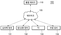
도 1은 일실시예에 따라, 본 발명과 관련된 스마트 관리 시스템(100)에 대한 개념도이다.1 is a conceptual diagram of a
네트워크 기술의 발달과 더불어 사무실 뿐만 아니라, 가정에서도 네트워크 구현이 가능하다. 도 1을 참고하면, 주거 공간에는 도어락 장치(131), 냉/난방 장치(132), TV(133)와 같은 가전 제품 및 조명 장치(134)가 설치된다. 도어락 장치(131), 냉/난방 장치(132), TV(133) 및 조명 장치(134)는 통합 제어기(110)에 의하여 관리될 수 있다.With the development of network technology, it is possible to implement a network not only in the office but also at home. Referring to FIG. 1 , home appliances such as a
일실시예에 따르면, 통합 제어기(110)는 유선 또는 무선으로 네트워크(120)와 연결되어, 도어락 장치(131), 냉/난방 장치(132), TV(133) 및 조명 장치(134)와 데이터를 주고 받을 수 있다. 통합 제어기(110)는 외부 디바이스와 통신을 가능하게 하는 하나 이상의 구성 요소를 포함할 수 있다. 예를 들면, 근거리 통신 모듈, 유선 통신 모듈 및 이동 통신 모듈을 포함할 수 있다.According to one embodiment, the
일실시예에 따르면, 네트워크(120)는 유선 통신 네트워크 및 무선 통신 네트워크를 포함한다. 여기서, 무선 통신 네트워크로는 무선 랜(Wireless LAN), 와이파이(wifi), 블루투스, 지그비(zigbee), WFD(Wifi-direct), UWB(ultra wideband), 적외선 통신(IrDA, infrared Data Association), BLE (Bluetooth Low Energy) 및 NFC(Near Field Communication) 등이 될 수 있고, 이에 한정되지 않는다.According to one embodiment,
도 1에 도시된 바와 같이, 도어락 장치(131), 냉/난방 장치 (132), TV(133) 및 조명 장치(134)는 하나의 통합 제어기(110)로 관리될 수 있다. 사용자는 통합 제어기(110)를 이용하여 각 장치의 전부 또는 일부를 일괄적으로 제어할 수 있다. 통합 제어기(110)는 스마트 폰(smart phone), 랩탑 컴퓨터, PDA, 태블릿 PC 등이 해당될 수 있으나, 이에 제한되지 않는다.As shown in FIG. 1 , the
도 2는 일실시예에 따라, 본 발명과 관련된 조명 제어 시스템(200)에 대한 개념도이다.2 is a conceptual diagram of a
도 2는 실내에 설치되는 복수의 조명 장치를 제어하는 조명 제어 시스템(200)을 도시한다. 무선 통신 기반의 조명 제어 시스템(200)은 서버(210), 무선 조명 제어기(220) 및 각 조명(231, 232, 233, 234, 235)에 탑재된 무선 모듈로 구성된다.2 illustrates a
일실시예에 따르면, 서버(210)는 조명 장치를 제어 및 관리하기 위한 정보를 저장할 수 있다. 구체적으로, 서버(210)는 조명 상태, 조명 종류, 전력 사용량, 조명 모드 설정, 전원 온/오프 기능에 대한 정보를 저장할 수 있다.According to an embodiment, the
일실시예에 따르면, 무선 조명 제어기(220)는 각 조명(231, 232, 233, 234, 235)등에 탑재된 무선 모듈과 무선 통신을 통해 연결된다. 서버(210)와 무선 조명 제어기(220)는 유선 또는 무선으로 연결될 수 있다. 각 조명(231, 232, 233, 234, 235)들에 탑재된 무선 모듈은 무선 조명 제어기(220)의 제어 명령에 따라 조명을 온 또는 오프하거나 밝기를 조절하는 역할을 수행한다.According to one embodiment, the
일실시예에 따르면, 조명 제어 시스템(200)에 포함된 서버(210), 무선 조명 제어기(220) 각 조명(231, 232, 233, 234, 235)에 탑재된 무선 모듈 중 일부 또는 전부는 하드웨어 모듈에 의해 동작할 수 있으나 이에 제한되지 않으며, 상술한 구성 중 일부가 소프트웨어에 의해 동작할 수도 있다.According to one embodiment, the
일실시예에 따르면, 원격지에서 컴퓨터나 휴대용 모바일 기기를 이용해 조명 제어 시스템(200)에 접속하고, 가정이나 사무실 등에 설치된 조명 장치를 제어할 수 있다. 구체적으로, 사용자는 노트북, PDA, 스마트 폰을 이용하여 조명 제어 시스템(200)의 웹페이지에 접속하고, 복수의 조명 장치들 전부 또는 일부를 제어할 수 있다. 따라서, 사용자는 가정이나 사무실에 설치된 복수 개의 조명들을 각각 제어할 수 있고, 각 조명(231, 232, 233, 234, 235) 기구의 전원 온/오프를 통해 불필요한 전원을 차단하여 전기 소모를 줄일 수 있다. 또한, 각 조명(231, 232, 233, 234, 235)의 밝기 등을 조절하여 최소의 조명이 제공될 수 있도록 하여 전기 소모량을 줄일 수 있다.According to an embodiment, it is possible to access the
일실시예에 따르면, 빌딩과 같은 대형 건물에서 복수의 조명 장치가 설치될 수 있다. 이러한 복수의 조명 장치를 개별 또는 그룹으로 제어하기 위해 도 2에 도시된 바와 같은 조명 제어 시스템(200)이 필요하다. 조명 제어 시스템(200)은 실시간으로 각 층 또는 특정 구역에 설치된 조명 장치의 온/오프, 밝기(dimming), 조명 장치의 상태 정보 및 전력 사용량을 관리함으로써 불필요한 에너지의 사용처를 검출하여 그 낭비를 최소화할 수 있다.According to an embodiment, a plurality of lighting devices may be installed in a large building such as a building. A
이 경우, 복수의 조명 장치가 설정된 네트워크 정보가 올바르지 않으면, 복수의 조명 장치의 전부 또는 일부를 제어하는 데에 어려움이 따를 수 있다. 조명 장치에 대한 네트워크 정보가 올바르지 않은 경우, 조명 제어 시스템(200)은 조명 장치에 대한 네트워크 정보를 초기화하고, 올바른 네트워크 정보를 설정할 수 있다.In this case, if the network information in which the plurality of lighting devices are set is not correct, it may be difficult to control all or some of the plurality of lighting devices. When the network information for the lighting device is incorrect, the
도 3은 일실시예에 따라, 무선 조명 네트워크의 설정을 설명하기 위한 도면이다.3 is a diagram for explaining the setting of a wireless lighting network, according to an embodiment.
일실시예에 따르면, 조명 제어 시스템은 서버, 게이트웨이, 리모콘, 무선 조명 제어 모듈이 포함된 조명 장치로 구성될 수 있다. 조명 장치를 제어하기 위해서는 네트워크 형성이 필요하며, 조명 장치들은 무선 조명 제어 네트워크의 조정 역할을 하는 게이트웨이로 연결되어야 한다.According to an embodiment, the lighting control system may be configured with a lighting device including a server, a gateway, a remote control, and a wireless lighting control module. Network formation is required to control the lighting devices, and the lighting devices need to be connected to a gateway that plays a role of coordinating the wireless lighting control network.
여기서, 게이트웨이는 스마트 기기와 무선으로 연결될 수 있는 무선 통신 모듈을 포함할 수 있고, 조명 장치의 조명 제어를 위해 조명 장치로 연결될 수 있는 무선 통신 모듈을 포함할 수 있다.Here, the gateway may include a wireless communication module that can be wirelessly connected to the smart device, and may include a wireless communication module that can be connected to the lighting device for lighting control of the lighting device.
일실시예에 따르면, 조명 장치가 연결되어야 할 제1 게이트웨이(320)가 아닌 제2 게이트웨이(350)에 연결되었을 때, 제2 게이트웨이(350)로 연결된 네트워크를 분리하여 제1 게이트웨이(320)로 네트워크를 형성하여야 한다.According to one embodiment, when the lighting device is connected to the
도 3을 참고하면, 제1 주거 공간(310) 및 제2 주거 공간(340)이 있다. 제1 주거 공간(310)에는 제1 게이트웨이(320) 및 제1 주거 공간(310)에서 이용될 조명 장치들(331, 332, 333)이 있다. 또한, 제2 주거 공간(340)에는 제2 게이트웨이(350) 및 제2 주거 공간(340)에서 이용될 조명 장치들(361, 362, 363)이 있다. 여기서, 각 주거 공간의 조명 장치들은 각 주거 공간의 게이트웨이에 연결되어야 한다.Referring to FIG. 3 , there are a first
제2 주거 공간(340)의 조명 장치들(361, 362, 363)이 제1 게이트웨이(320)로 연결된다면, 제2 게이트웨이(350)에서는 제2 주거 공간(340)의 조명 장치들(361, 362, 363)을 제어할 수 없게 된다. 따라서, 제2 주거 공간(340)의 조명 장치들(361, 362, 363)은 제1 게이트웨이(320)로 연결된 네트워크를 분리하고, 제2 게이트웨이(350)로 연결되도록 네트워크를 재형성 해야 한다. 제2 주거 공간(340)의 조명 장치들(361, 362, 363)은 네트워크 정보를 초기화함으로써, 제1 게이트웨이(320)로 연결된 네트워크를 분리할 수 있다.If the
일실시예에 따르면, 조명 장치의 전원이 온(ON)이 되는 경우, 조명 장치는 메모리에 저장된 네트워크 정보를 확인하여, 유효할 경우 별도의 프로세스를 거치지 않는다. 그러나, 네트워크 정보가 유효하지 않은 경우, 조명 장치는 네트워크 정보를 초기화하고, 조명 장치가 올바르게 연결되어야 할 네트워크 정보를 등록한다.According to an embodiment, when the power of the lighting device is turned on, the lighting device checks the network information stored in the memory, and if valid, does not go through a separate process. However, if the network information is not valid, the lighting device initializes the network information and registers the network information to which the lighting device should be connected correctly.
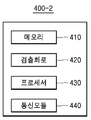
도 4a는 일실시예에 따른 조명 장치(400-1)의 구성을 도시한 블록도이다.4A is a block diagram illustrating a configuration of a lighting device 400 - 1 according to an exemplary embodiment.
일실시예에 따르면, 조명 장치(400-1)는 메모리(410), 검출회로(420) 및 프로세서(430)를 포함할 수 있다. 그러나, 도시된 구성 요소 모두가 필수 구성 요소인 것은 아니다. 도시된 구성요소보다 많은 구성 요소에 의해 조명 장치(400-1)가 구현될 수 있고, 그보다 적은 구성 요소에 의해서도 조명 장치(400-1)가 구현될 수 있다. 이하 상기 구성 요소들에 대해 살펴본다.According to an embodiment, the lighting device 400 - 1 may include a
일실시예에 따르면, 메모리(410)는 조명 장치(400-1)의 무선 네트워크 정보를 저장한다. 여기서, 무선 네트워크 정보는 게이트웨이의 정보, 무선 제어 장치의 정보, 네트워크 ID 정보, MAC 주소 및 조명 장치(400-1)의 노드 정보 중 적어도 하나를 포함할 수 있고, 이에 한정되지 않는다. 또한, 메모리(410)는 플래시 메모리(410), 하드디스크, EEPROM 등 여러 가지 종류의 저장매체로 구현될 수 있다.According to one embodiment, the
일실시예에 따르면, 검출회로(420)는 조명 장치(400-1)에 공급되는 교류 신호를 검출한다. 여기서, 교류는 시간에 따라 크기와 방향이 주기적으로 변화는 전류로서 일반적으로 AC(Alternating Current)로 나타낸다. 교류는 사인 파형일 수 있고, 사각파나 삼각파 등을 포함한다. 교류 신호는 교류를 의미할 수 있고, 교류 전원 신호도 의미할 수 있다. 검출회로(420)는 미리 지정한 시간 동안 교류 신호의 온 상태의 횟수와 오프 상태의 횟수를 검출한다.According to an embodiment, the
일실시예에 따르면, 검출회로(420)는 주기적으로 교류 신호의 온 상태 및 오프 상태를 검출하도록 설정될 수 있다. 검출회로(420)는 교류 신호의 온 상태의 횟수와 오프 상태의 횟수를 검출하면서 처음 오프 상태의 시점부터 마지막 온 상태의 시점까지의 시간을 검출할 수 있다. 예를 들면, 검출회로(420)는 10초 동안 교류 신호의 온 상태 및 오프 상태가 몇 번이 있었는지를 검출하도록 설정될 수 있다.According to an embodiment, the
일실시예에 따르면, 프로세서(430)는 검출된 교류 신호에 기초하여, 조명 장치(400-1)의 무선 네트워크 정보를 초기화한다. 프로세서(430)는 무선 네트워크 정보를 초기화할 것으로 결정된 정보를 획득한다. 프로세서(430)는 교류 신호의 온 상태 횟수와 오프 상태의 횟수에 기초하여 무선 네트워크 정보를 초기화할 것으로 결정된 정보를 획득한다. 예를 들면, 교류 신호의 온 상태 횟수와 오프 상태의 횟수가 미리 지정된 횟수보다 큰 경우, 프로세서(430)는 무선 네트워크 정보를 초기화할 수 있다. 구체적으로, 온 상태 횟수 및 오프 상태의 횟수가 10초 동안 7회 이상인 경우, 무선 네트워크 정보는 초기화되도록 설정될 수 있다.According to an embodiment, the
여기서, 프로세서(430)가 직접 교류 신호에 기초하여 조명 장치(400-1)의 무선 네트워크 정보를 초기화할 것인지를 결정할 수 있다. 또한, 프로세서(430)는 조명 장치(400-1)의 다른 구성 또는 외부 장치가 무선 네트워크 정보를 초기화할 것으로 결정한 정보를 수신하고, 수신된 정보에 따라 무선 네트워크 정보를 초기화할 수 있다. 예를 들면, 교류 신호의 온/오프 상태를 반복하면, 조명 장치(400-1)의 전원 공급부에서 통신 모듈로 교류 신호를 전달하고, 통신 모듈에서는 교류 신호에 대한 온 상태 및 오프 상태를 검출하여 무선 네트워크 정보를 초기화할 것으로 결정할 수 있다. 통신 모듈은 결정된 정보를 프로세서(430)로 전달하고, 프로세서(430)는 무선 네트워크 정보를 초기화할 수 있다.Here, the
또한, 프로세서(430)는 무선 네트워크 정보를 초기화하는 것 이외에 조명 장치(400-1)의 발광부의 온/오프, 조도 및 색온도 중 적어도 하나를 제어할 수 있다.In addition, the
일실시예에 따르면, 검출회로(420)는 입력부, 제1 변환부, 제2 변환부, 제3 변환부 및 출력부를 포함할 수 있다. 그러나, 상기 언급한 검출회로(420)의 구성 요소가 필수 구성 요소인 것은 아니다. 언급한 구성 요소보다 많은 구성 요소에 의해 검출회로(420)가 구현될 수 있다.According to an embodiment, the
검출회로(420)의 구성을 상세하게 설명하면, 입력부는 교류 신호를 인가 받는다. 제1 변환부는 교류 신호를 제1 직류 신호로 변환한다. 제2 변환부는 제1 직류 신호를 통신 모듈에 미리 설정된 제2 직류 신호로 변환한다. 제3 변환부는 통신 모듈에서 디지털 신호로 변환 가능한 레벨로 교류 신호를 변환한다. 출력부는 변환된 교류 신호 및 제2 직류 신호를 출력한다. 검출회로(420) 구성의 연결관계는 도 5 내지 도 8에서 설명한다.When describing the configuration of the
도 4b는 다른 일실시예에 따른 조명 장치(400-2)의 구성을 도시한 블록도이다. 도 4b에 도시된 조명 장치(400-2)는 도 4a에 비하여, 통신 모듈(440)을 더 포함할 수 있다.4B is a block diagram illustrating a configuration of a lighting device 400 - 2 according to another exemplary embodiment. The lighting device 400 - 2 illustrated in FIG. 4B may further include a
도 4b에 있어서, 조명 장치(400-2)의 메모리(410), 검출회로(420) 및 프로세서(430)는 도 4a에서의 조명 장치(400-2)의 각 구성과 동일 대응되므로, 도 4a에서와 중복되는 설명은 생략한다.In FIG. 4B , the
일실시예에 따르면, 통신 모듈(440)은 조명 장치(400-2)의 무선 네트워크를 설정한다. 프로세서(430)가 무선 네트워크 정보를 초기화하면, 통신 모듈(440)은 무선 네트워크 정보를 초기화가 이루어지기 전에 설정된 무선 네트워크와 상이한 무선 네트워크로 설정한다.According to an embodiment, the
또한, 통신 모듈(440)은 조명 장치(400-2)의 발광부에 대한 제어 신호를 외부 장치 또는 프로세서(430)로부터 수신하고, 발광부의 작동 상태를 외부 장치로 송신할 수 있다. 통신 모듈(440)은 발광부를 제어하기 위한 제어부를 포함할 수 있다. 또한, 제어부는 발광부의 PWM(Pulse Width Modulation) 제어를 위한 출력단 및 센서로부터 감지된 상태 정보가 입력되는 ADC(Analog to Digital Converter) 입력단을 포함할 수 있다. 여기서, 상태 정보는 온도 정보, 조도 정보 및 재실자 정보 중 적어도 하나를 포함할 수 있다.Also, the
일실시예에 따르면, 통신 모듈(440)은 소정 거리 이내의 근거리 통신을 위한 모듈을 의미한다. 본 발명의 일 실시 예에 따른 근거리 통신 기술에는 무선 랜(Wireless LAN), 와이파이(Wi-Fi), 블루투스, 지그비(zigbee), WFD(Wi-Fi Direct), UWB(ultra wideband), 적외선 통신(IrDA, infrared Data Association), BLE (Bluetooth Low Energy), NFC(Near Field Communication) 등이 있을 수 있으나, 이에 한정되는 것은 아니다.According to an embodiment, the
일실시예에 따르면, 조명 장치(400-2)는 벌브(Bulb) 타입, PAR(Parabolic Aluminized Reflector Lamp) 타입 및 평판형 타입의 조명 장치(400-2)일 수 있으며, 이에 한정되지 않는다.According to an embodiment, the lighting device 400 - 2 may be a bulb type, a parabolic aluminized reflector lamp (PAR) type, and a flat type lighting device 400 - 2 , but is not limited thereto.
조명 장치는 중앙 연산 프로세서를 구비하여, 메모리, 검출회로, 프로세서 및 통신 모듈의 동작을 총괄적으로 제어할 수 있다. 중앙 연산 프로세서는 다수의 논리 게이트들의 어레이로 구현될 수도 있고, 범용적인 마이크로 프로세서와 이 마이크로 프로세서에서 실행될 수 있는 프로그램이 저장된 메모리의 조합으로 구현될 수도 있다. 또한, 다른 형태의 하드웨어로 구현될 수도 있음을 본 실시예가 속하는 기술분야에서 통상의 지식을 가진 자라면 이해할 수 있다.The lighting device may include a central processing processor to collectively control operations of the memory, the detection circuit, the processor, and the communication module. The central operation processor may be implemented as an array of a plurality of logic gates, or may be implemented as a combination of a general-purpose microprocessor and a memory in which a program executable in the microprocessor is stored. In addition, it can be understood by those skilled in the art that the present embodiment may be implemented in other types of hardware.
이하에서는, 조명 장치가 수행하는 다양한 동작이나 응용들이 설명되는데, 상기 메모리, 검출회로, 프로세서 및 통신 모듈 중 어느 구성을 특정하지 않더라도 본 발명의 기술분야에 대한 통상의 기술자가 명확하게 이해하고 예상할 수 있는 정도의 내용은 통상의 구현으로 이해될 수 있으며, 본 발명의 권리범위가 특정한 구성의 명칭이나 물리적/논리적 구조에 의해 제한되는 것은 아니다.Hereinafter, various operations or applications performed by the lighting device are described, and those skilled in the art can clearly understand and expect without specifying any configuration of the memory, the detection circuit, the processor, and the communication module. Content to the extent that it can be understood as a typical implementation, the scope of the present invention is not limited by the name or physical / logical structure of a specific configuration.
도 5는 일실시예에 따른 조명 장치의 검출회로의 구성 간 연결관계를 나타낸 블록도이다.5 is a block diagram illustrating a connection relationship between components of a detection circuit of a lighting device according to an exemplary embodiment.
도 5를 참고하면, 검출회로(420)는 입력부(510), 제1 변환부(520), 제2 변환부(530), 제3 변환부(540) 및 출력부(550)를 포함한다. 여기서, 도 4에서와 중복되는 설명은 생략한다. 검출회로(420)는 도시된 구성요소보다 많은 구성 요소에 의해 검출회로(420)가 구현될 수 있고, 그보다 적은 구성 요소에 의해서도 검출회로(420)가 구현될 수도 있다.Referring to FIG. 5 , the
일실시예에 따르면, 제1 변환부(520)는 및 제2 변환부(530)는 직렬로 연결되고, 제3 변환부(540)는 제1 변환부(520)의 입력단 및 제2 변환부(530)의 출력단과 병렬로 연결될 수 있다. 제1 변환부(520)의 입력단 및 제3 변환부(540)의 입력단은 입력부(510)와 직렬로 연결될 수 있다. 제2 변환부(530)의 출력단 및 제3 변환부(540)의 출력단은 출력부(550)와 직렬로 연결될 수 있다. 출력부(550)는 교류 신호의 온 상태 또는 오프 상태를 감지할 수 있다. 출력부(550)에 대해 구체적인 예를 들면, 출력부(550)는 통신 모듈의 ADC(Analog to Digital Converter)로 구성될 수 있다.According to an embodiment, the
도 6은 일실시예에 따라, 도 5의 블록도를 상세하게 도시한 회로도이다.6 is a circuit diagram illustrating the block diagram of FIG. 5 in detail, according to an embodiment.
일실시예에 따르면, 조명 장치의 검출회로(420)는 교류 신호의 온 상태 또는 오프 상태를 검출하기 위해 도 6의 회로도와 같이 구성될 수 있다.According to an embodiment, the
일실시예에 따르면, 제1 변환부(520)는 교류 신호를 제1 직류 신호로 변환한다. 제1 변환부(520)는 다이오드, 인덕터 및 저항을 포함할 수 있다. 제2 변환부(530)는 제1 직류 신호를 통신 모듈에 미리 설정된 제2 직류 신호로 변환한다. 제3 변환부(540)는 통신 모듈에서 디지털 신호로 변환 가능한 레벨로 교류 신호를 변환한다. 여기서, 제3 변환부(540)는 적어도 둘 이상의 저항들 및 적어도 하나의 커패시터를 포함한다. 구체적으로, 적어도 하나의 커패시터는 적어도 하나의 둘 이상의 저항들 중 하나의 저항과 병렬로 연결될 수 있다. 도 5에서 설명한 바와 같이, 출력부(550)는 통신 모듈과 대응될 수 있다. 도 6은 구체적인 회로의 구성소자 등과 같은 많은 특정사항들이 도시되어 있는데, 이는 본 발명을 보다 전반적인 이해를 돕기 위해서 제공된 것일 뿐 이러한 특정 사항들 없이도 본 발명이 실시될 수 있음은 관련 기술 분야에서 통상의 지식을 가진 자에게는 자명하다 할 것이다. 또한, 도 6에 도시된 구성요소들 외에 다른 범용적인 구성요소들이 더 포함될 수 있음을 관련 기술 분야에서 통상의 지식을 가진 자라면 이해할 수 있다.According to an embodiment, the
일실시예에 따르면, 교류 전원이 오프되더라도, 인덕터 또는 커패시터에 에너지가 저장되어 있기 때문에, 저장된 에너지는 짧은 시간 동안 통신 모듈이 동작할 수 있도록 전력을 공급한다. 이 경우, 조명 장치의 통신 모듈은 정상적인 동작을 유지한다.According to an embodiment, even when the AC power is turned off, since energy is stored in the inductor or capacitor, the stored energy supplies power so that the communication module can operate for a short time. In this case, the communication module of the lighting device maintains a normal operation.
일실시예에 따르면, 제3 변환부(540)에 도시된 저항 R1 및 R2의 비율을 조정하여 통신 모듈의 ADC(Analog to Digital Converter) 동작 범위 내로 입력이 가능하게 할 수 있다. 또한, 검출회로(420)에서 교류 신호의 오프 상태가 검출되면, 조명 장치는 통신 모듈에 공급되는 파워를 유지하기 위해 LED 드라이버쪽으로 나가는 PWM(Pulse Width Modulation) 신호를 오프하고 불필요한 전력이 낭비되지 않도록 한다.According to an embodiment, by adjusting the ratio of the resistors R1 and R2 shown in the
도 6에 도시된 검출회로(420)는 도 8에 도시된 검출회로(420)보다 응답 속도가 빠르기 때문에 조명 장치의 네트워크를 초기화하는데 더 효율적으로 이용될 수 있다.Since the
도 7은 다른 일실시예에 따른 조명 장치의 검출회로의 구성 간 연결관계를 나타낸 블록도이다.7 is a block diagram illustrating a connection relationship between components of a detection circuit of a lighting device according to another exemplary embodiment.
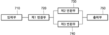
도 7을 참고하면, 검출회로(420)는 입력부(710), 제1 변환부(720), 제2 변환부(730), 제3 변환부(740) 및 출력부(750)를 포함한다. 여기서, 도 4에서와 중복되는 설명은 생략한다.Referring to FIG. 7 , the
다른 일실시예에 따르면, 제2 변환부(730)는 제3 변환부(740)와 병렬로 연결되고, 제1 변환부(720)의 출력단은 제2 변환부(730) 및 제3 변환부(740)가 연결된 병렬회로의 입력단과 직렬로 연결된다. 입력부(710)와 제1 변환부(720)는 직렬로 연결된다. 제2 변환부(730) 및 제3 변환부(740)가 연결된 병렬회로의 출력단은 출력부(750)와 직렬로 연결된다.According to another embodiment, the
도 8은 일실시예에 따라, 도 7의 블록도를 상세하게 도시한 회로도이다.8 is a circuit diagram illustrating the block diagram of FIG. 7 in detail, according to an embodiment.
도 8에 도시된 입력부(710), 제1 변환부(720), 제2 변환부(730), 제3 변환부(740) 및 출력부(750)는 도 6의 구성의 입력부(710), 제1 변환부(720), 제2 변환부(730), 제3 변환부(740) 및 출력부(750)와 대응되므로, 도 6에서와 중복되는 설명은 생략한다. 도 8의 제3 변환부(740)는 도 6의 제3 변환부(740)와 다르게 제2 변환부(730)만 병렬로 연결된다.The
도 8에 도시된 구성요소들 외에 다른 범용적인 구성요소들이 더 포함될 수 있음을 관련 기술 분야에서 통상의 지식을 가진 자라면 이해할 수 있다.Those of ordinary skill in the art may understand that other general-purpose components may be further included in addition to the components shown in FIG. 8 .
도 9는 일실시예에 따라, 시간에 따라 검출된 교류신호를 나타낸 그래프이다.9 is a graph illustrating an AC signal detected over time, according to an exemplary embodiment.
도 9는 검출회로를 도 8로 구성하였을 때, 출력되는 복수의 파형(920, 930)을 도시한다. 도 9를 참고하면, 교류 신호(910)의 입력이 온/오프가 반복되면, 도 8에 도시된 제3 변환부의 저항 R1 및 R2 사이의 전압이 도 9의 제1 파형(920)으로 도시된다. 이 경우, 통신 모듈의 전압은 도 9의 제2 파형(930)으로 도시된다. 통신 모듈은 ADC(Analog to Digital Converter)를 통하여 통신 모듈의 전압의 변화를 확인할 수 있다.FIG. 9 shows a plurality of
도 10은 일실시예에 따라, 조명 장치의 네트워크를 설정하는 흐름을 나타낸 순서도이다.10 is a flowchart illustrating a flow of setting a network of lighting devices, according to an embodiment.
도 10을 참고하면, 단계 S1010에서, 조명 장치는 사용자의 물리적인 스위치 온(ON) 또는 사용자의 조명 온 신호를 수신하여 조명을 온(ON)할 수 있다.Referring to FIG. 10 , in step S1010 , the lighting device may turn on the lighting by receiving the user's physical switch-on (ON) or the user's lighting-on signal.
단계 S1020에서, 조명 장치는 조명 장치의 메모리에 저장된 무선 네트워크 정보를 확인한다. 여기서, 무선 네트워크 정보는 게이트웨이의 정보, 무선 제어 장치의 정보, 네트워크 ID 정보, MAC 주소 및 조명 장치의 노드 정보 중 적어도 하나를 포함할 수 있고, 이에 한정되지 않는다.In step S1020, the lighting device checks the wireless network information stored in the memory of the lighting device. Here, the wireless network information may include at least one of gateway information, wireless control device information, network ID information, MAC address, and lighting device node information, but is not limited thereto.
단계 S1030에서, 조명 장치는 무선 네트워크 정보가 유효한지를 확인한다. 무선 네트워크 정보가 유효하면, 조명 장치는 무선 네트워크 정보를 유지한다. 무선 네트워크 정보가 유효하지 않으면, 조명 장치는 단계 S1040을 수행한다.In step S1030, the lighting device checks whether the wireless network information is valid. If the wireless network information is valid, the lighting device maintains the wireless network information. If the wireless network information is not valid, the lighting device performs step S1040.
예를 들면, 제1 게이트웨이에 연결되어야 할 제1 조명 장치가 제2 게이트웨이에 연결된 경우, 제1 조명 장치는 제1 조명 장치에 대한 무선 네트워크 정보를 유효하지 않은 것으로 결정할 수 있다. 이 경우, 제1 조명 장치는 무선 네트워크 정보를 초기화를 하고, 제1 게이트웨이에 제1 조명 장치가 연결되도록 한다.For example, when the first lighting device to be connected to the first gateway is connected to the second gateway, the first lighting device may determine that the wireless network information for the first lighting device is invalid. In this case, the first lighting device initializes the wireless network information and connects the first lighting device to the first gateway.
단계 S1040에서, 조명 장치는 무선 네트워크 정보를 재설정한다. 조명 장치는 기존에 설치되어 있던 무선 네트워크 정보를 초기화하고, 조명 장치가 연결되어야 무선 네트워크로 네트워크 정보를 재설정한다.In step S1040, the lighting device resets the wireless network information. The lighting device initializes the previously installed wireless network information, and resets the network information to the wireless network only when the lighting device is connected.
도 11은 일실시예에 따라, 조명 장치의 네트워크를 설정하는 흐름을 나타낸 순서도이다.11 is a flowchart illustrating a flow of setting a network of a lighting device, according to an embodiment.
도 11을 참고하면, 단계 S1110에서, 조명 장치는 조명 장치에 공급되는 교류 신호를 검출한다. 교류 신호는 교류를 의미할 수 있고, 교류 전원 신호도 의미할 수 있다.Referring to FIG. 11 , in step S1110, the lighting device detects an AC signal supplied to the lighting device. The AC signal may mean AC, and may also mean an AC power signal.
단계 S1120에서, 조명 장치는 검출된 교류 신호에 기초하여, 조명 장치의 무선 네트워크 정보를 초기화한다. 조명 장치의 무선 네트워크 정보를 초기화하는 과정은 도 12에서 상세하게 설명한다.In step S1120, the lighting device initializes wireless network information of the lighting device based on the detected AC signal. A process of initializing the wireless network information of the lighting device will be described in detail with reference to FIG. 12 .
단계 S1130에서, 조명 장치는 초기화에 따라 조명 장치의 무선 네트워크를 설정한다.In step S1130, the lighting device sets up a wireless network of the lighting device according to initialization.
도 12는 다른 일실시예에 따라, 조명 장치의 네트워크를 설정하는 흐름을 나타낸 순서도이다.12 is a flowchart illustrating a flow of setting a network of a lighting device according to another embodiment.
도 12를 참고하면, 단계 S1210에서, 조명 장치는 미리 지정한 시간 동안 조명 장치에 공급되는 교류 신호의 온 상태 횟수 및 오프 상태의 횟수를 검출한다.Referring to FIG. 12 , in step S1210 , the lighting apparatus detects the number of on-states and the number of off-states of the AC signal supplied to the lighting apparatus for a predetermined time period.
단계 S1220에서, 조명 장치는 검출된 온 상태 횟수 및 오프 상태의 횟수가 미리 지정된 횟수보다 큰지를 확인한다. 검출된 횟수가 미리 지정된 횟수보다 크면, 조명 장치는 단계 S1230을 수행한다. 검출된 횟수가 미리 지정된 횟수보다 작으면, 조명 장치는 단계 S1210을 수행한다.In step S1220, the lighting device checks whether the detected number of on-states and the number of off-states are greater than a predetermined number of times. If the detected number of times is greater than the predetermined number of times, the lighting apparatus performs step S1230. If the detected number of times is less than the predetermined number of times, the lighting apparatus performs step S1210.
단계 S1230에서, 조명 장치는 무선 네트워크 정보를 초기화한다.In step S1230, the lighting device initializes the wireless network information.
구체적으로 예를 들면, 교류 신호의 온 상태 횟수 및 오프 상태 횟수가 10초 동안 8번을 초과하면, 조명 장치의 네트워크 정보를 초기화하는 것으로 설정될 수 있다. 10초 동안 온 상태 횟수 및 오프 상태의 횟수가 9번인 경우, 조명 장치는 조명 장치의 네트워크 정보를 초기화할 수 있다.Specifically, for example, when the number of on-states and off-states of the AC signal exceeds 8 times for 10 seconds, it may be set to initialize network information of the lighting device. When the number of on-states and the number of off-states is 9 for 10 seconds, the lighting device may initialize network information of the lighting device.
다른 방식으로, 조명 장치는 교류 신호의 처음 오프 상태부터 8번의 온 상태까지의 시간을 계산하고, 10초를 초과하였는지를 확인할 수 있다. 10초를 초과하면, 조명 장치는 조명 장치의 네트워크 정보를 초기화할 수 있다.Alternatively, the lighting device may calculate a time from the first OFF state of the AC signal to the eight on states, and determine whether 10 seconds has been exceeded. When it exceeds 10 seconds, the lighting device may initialize network information of the lighting device.
단계 S1240에서, 조명 장치는 무선 네트워크 정보를 초기화가 이루어지기 전에 설정된 네트워크와 상이한 네트워크로 설정한다.In step S1240, the lighting device sets the wireless network information to a network different from the network set before initialization is made.
이상에서 설명된 장치는 하드웨어 구성요소, 소프트웨어 구성요소, 및/또는 하드웨어 구성요소 및 소프트웨어 구성요소의 조합으로 구현될 수 있다. 예를 들어, 실시예들에서 설명된 장치 및 구성요소는, 예를 들어, 프로세서, 콘트롤러, ALU(arithmetic logic unit), 디지털 신호 프로세서(digital signal processor), 마이크로컴퓨터, FPA(field programmable array), PLU(programmable logic unit), 마이크로프로세서, 또는 명령(instruction)을 실행하고 응답할 수 있는 다른 어떠한 장치와 같이, 하나 이상의 범용 컴퓨터 또는 특수 목적 컴퓨터를 이용하여 구현될 수 있다.The device described above may be implemented as a hardware component, a software component, and/or a combination of the hardware component and the software component. For example, devices and components described in the embodiments may include, for example, a processor, a controller, an arithmetic logic unit (ALU), a digital signal processor, a microcomputer, a field programmable array (FPA), It may be implemented using one or more general purpose or special purpose computers, such as a programmable logic unit (PLU), microprocessor, or any other device capable of executing and responding to instructions.
처리 장치는 운영 체제(OS) 및 상기 운영 체제 상에서 수행되는 하나 이상의 소프트웨어 애플리케이션을 수행할 수 있다. 또한, 처리 장치는 소프트웨어의 실행에 응답하여, 데이터를 접근, 저장, 조작, 처리 및 생성할 수도 있다.The processing device may execute an operating system (OS) and one or more software applications running on the operating system. The processing device may also access, store, manipulate, process, and generate data in response to execution of the software.
이해의 편의를 위하여, 처리 장치는 하나가 사용되는 것으로 설명된 경우도 있지만, 해당 기술분야에서 통상의 지식을 가진 자는, 처리 장치가 복수 개의 처리 요소(processing element) 및/또는 복수 유형의 처리 요소를 포함할 수 있음을 알 수 있다. 예를 들어, 처리 장치는 복수 개의 프로세서 또는 하나의 프로세서 및 하나의 콘트롤러를 포함할 수 있다. 또한, 병렬 프로세서(parallel processor)와 같은, 다른 처리 구성(processing configuration)도 가능하다.For convenience of understanding, although one processing device is sometimes described as being used, one of ordinary skill in the art will recognize that the processing device includes a plurality of processing elements and/or a plurality of types of processing elements. It can be seen that can include For example, the processing device may include a plurality of processors or one processor and one controller. Other processing configurations are also possible, such as parallel processors.
소프트웨어는 컴퓨터 프로그램(computer program), 코드(code), 명령(instruction), 또는 이들 중 하나 이상의 조합을 포함할 수 있으며, 원하는 대로 동작하도록 처리 장치를 구성하거나 독립적으로 또는 결합적으로(collectively) 처리 장치를 명령할 수 있다.The software may comprise a computer program, code, instructions, or a combination of one or more thereof, which configures a processing device to operate as desired or is independently or collectively processed You can command the device.
소프트웨어 및/또는 데이터는, 처리 장치에 의하여 해석되거나 처리 장치에 명령 또는 데이터를 제공하기 위하여, 어떤 유형의 기계, 구성요소(component), 물리적 장치, 가상 장치(virtual equipment), 컴퓨터 저장 매체 또는 장치, 또는 전송되는 신호 파(signal wave)에 영구적으로, 또는 일시적으로 구체화(embody)될 수 있다. 소프트웨어는 네트워크로 연결된 컴퓨터 시스템 상에 분산되어서, 분산된 방법으로 저장되거나 실행될 수도 있다. 소프트웨어 및 데이터는 하나 이상의 컴퓨터 판독 가능 기록 매체에 저장될 수 있다.The software and/or data may be any kind of machine, component, physical device, virtual equipment, computer storage medium or device, to be interpreted by or to provide instructions or data to the processing device. , or may be permanently or temporarily embody in a transmitted signal wave. The software may be distributed over networked computer systems, and stored or executed in a distributed manner. Software and data may be stored in one or more computer-readable recording media.
실시예에 따른 방법은 다양한 컴퓨터 수단을 통하여 수행될 수 있는 프로그램 명령 형태로 구현되어 컴퓨터 판독 가능 매체에 기록될 수 있다. 상기 컴퓨터 판독 가능 매체는 프로그램 명령, 데이터 파일, 데이터 구조 등을 단독으로 또는 조합하여 포함할 수 있다. 상기 매체에 기록되는 프로그램 명령은 실시예를 위하여 특별히 설계되고 구성된 것들이거나 컴퓨터 소프트웨어 당업자에게 공지되어 사용 가능한 것일 수도 있다.The method according to the embodiment may be implemented in the form of program instructions that can be executed through various computer means and recorded in a computer-readable medium. The computer-readable medium may include program instructions, data files, data structures, etc. alone or in combination. The program instructions recorded on the medium may be specially designed and configured for the embodiment, or may be known and available to those skilled in the art of computer software.
컴퓨터 판독 가능 기록 매체의 예에는 하드 디스크, 플로피 디스크 및 자기 테이프와 같은 자기 매체(magnetic media), CD-ROM, DVD와 같은 광기록 매체(optical media), 플롭티컬 디스크(floptical disk)와 같은 자기-광 매체(magneto-optical media), 및 롬(ROM), 램(RAM), 플래시 메모리 등과 같은 프로그램 명령을 저장하고 수행하도록 특별히 구성된 하드웨어 장치가 포함된다.Examples of the computer-readable recording medium include magnetic media such as hard disks, floppy disks and magnetic tapes, optical media such as CD-ROMs and DVDs, and magnetic such as floppy disks. - includes magneto-optical media, and hardware devices specially configured to store and carry out program instructions, such as ROM, RAM, flash memory, and the like.
프로그램 명령의 예에는 컴파일러에 의해 만들어지는 것과 같은 기계어 코드뿐만 아니라 인터프리터 등을 사용해서 컴퓨터에 의해서 실행될 수 있는 고급 언어 코드를 포함한다.Examples of program instructions include not only machine language codes such as those generated by a compiler, but also high-level language codes that can be executed by a computer using an interpreter or the like.
상기된 하드웨어 장치는 실시예의 동작을 수행하기 위해 하나 이상의 소프트웨어 모듈로서 작동하도록 구성될 수 있으며, 그 역도 마찬가지이다.The hardware devices described above may be configured to operate as one or more software modules to perform the operations of the embodiments, and vice versa.
이상과 같이 실시예들이 비록 한정된 실시예와 도면에 의해 설명되었으나, 해당 기술분야에서 통상의 지식을 가진 자라면 상기의 기재로부터 다양한 수정 및 변형이 가능하다. 예를 들어, 설명된 기술들이 설명된 방법과 다른 순서로 수행되거나, 및/또는 설명된 시스템, 구조, 장치, 회로 등의 구성요소들이 설명된 방법과 다른 형태로 결합 또는 조합되거나, 다른 구성요소 또는 균등물에 의하여 대치되거나 치환되더라도 적절한 결과가 달성될 수 있다.As described above, although the embodiments have been described with reference to the limited embodiments and drawings, various modifications and variations are possible from the above description by those skilled in the art. For example, the described techniques are performed in a different order than the described method, and/or the described components of the system, structure, apparatus, circuit, etc. are combined or combined in a different form than the described method, or other components Or substituted or substituted by equivalents may achieve an appropriate result.
그러므로, 본 발명의 범위는 설명된 실시예에 국한되어 정해져서는 아니 되며, 후술하는 특허청구범위뿐 아니라 이 특허청구범위와 균등한 것들에 의해 정해져야 한다.Therefore, the scope of the present invention should not be limited to the described embodiments, but should be defined by the following claims as well as the claims and equivalents.
Claims (20)
상기 조명 장치에 공급되는 교류 신호를 검출하는 검출회로; 및
상기 조명 장치에 전원이 입력되면, 상기 조명 장치의 무선 네트워크 정보가 유효한지 결정하는 프로세서를 포함하고,
상기 프로세서는,
상기 저장된 무선 네트워크 정보에 기초하여, 상기 조명 장치가 네트워크에 연결되고 상기 네트워크를 통해 제어되기 위해 이전에 사용된 네트워크 정보가 유효한지 결정하며,
상기 네트워크 정보가 유효한 경우, 상기 네트워크 정보를 유지하고,
상기 네트워크 정보가 유효하지 않은 경우, 상기 검출된 교류 신호에 기초하여 상기 조명 장치에 의해 사용될 수 있는 네트워크 정보로 상기 네트워크 정보를 재설정하고,
상기 유지 또는 재설정된 네트워크 정보를 사용하여 상기 조명 장치가 현재 위치하는 공간의 네트워크에 상기 조명 장치를 연결하는, 조명 장치.a memory for storing wireless network information of the lighting device;
a detection circuit for detecting an AC signal supplied to the lighting device; and
When power is input to the lighting device, including a processor for determining whether the wireless network information of the lighting device is valid,
The processor is
determine, based on the stored wireless network information, whether network information previously used for the lighting device to be connected to a network and to be controlled through the network is valid;
If the network information is valid, maintain the network information,
when the network information is not valid, reset the network information to network information that can be used by the lighting device based on the detected AC signal;
Connecting the lighting device to a network of a space in which the lighting device is currently located using the maintained or reset network information.
상기 조명 장치의 무선 네트워크를 통해 외부 제어 장치로부터 제어 신호를 수신하는 통신모듈을 더 포함하는, 조명 장치.According to claim 1,
The lighting device further comprising a communication module for receiving a control signal from an external control device through the wireless network of the lighting device.
상기 검출회로는, 미리 지정한 시간 동안 상기 교류 신호의 온 상태의 횟수와 오프 상태의 횟수를 검출하고,
상기 프로세서는, 상기 온 상태의 횟수와 상기 오프 상태의 횟수에 기초하여 상기 무선 네트워크 정보를 재설정할 것으로 결정하는, 조명 장치.According to claim 1,
The detection circuit detects the number of on-states and the number of off-states of the AC signal for a predetermined time period,
The processor determines to reset the wireless network information based on the number of times of the on state and the number of times of the off state, the lighting device.
상기 횟수가 미리 지정된 횟수보다 큰 경우,
상기 프로세서는, 상기 무선 네트워크 정보를 재설정할 것으로 결정하는, 조명 장치.5. The method of claim 4,
If the number of times is greater than a predetermined number of times,
and the processor determines to reset the wireless network information.
상기 무선 네트워크 정보는, 상기 조명 장치를 제어하는 게이트웨이의 식별 정보를 포함하는, 조명 장치.According to claim 1,
The wireless network information, including identification information of a gateway for controlling the lighting device, lighting device.
상기 검출회로는,
상기 교류 신호를 인가 받는 입력부;
상기 교류 신호를 제1 직류 신호로 변환하는 제1 변환부;
상기 제1 직류 신호를 상기 통신모듈에 미리 설정된 제2 직류 신호로 변환하는 제2 변환부;
상기 통신모듈에서 디지털 신호로 변환 가능한 레벨로 상기 교류 신호를 변환하는 제3 변환부; 및
상기 변환된 교류 신호 및 상기 제2 직류 신호를 출력하는 출력부를 포함하는, 조명 장치.3. The method of claim 2,
The detection circuit is
an input unit receiving the AC signal;
a first converter converting the AC signal into a first DC signal;
a second converter converting the first DC signal into a second DC signal preset in the communication module;
a third conversion unit for converting the AC signal to a level convertible into a digital signal in the communication module; and
and an output unit for outputting the converted AC signal and the second DC signal.
상기 제1 변환부 및 상기 제2 변환부는 직렬로 연결되고, 상기 제3 변환부는 상기 제1 변환부의 입력단 및 상기 제2 변환부의 출력단과 병렬로 연결된 것을 특징으로 하는, 조명 장치.9. The method of claim 8,
The first conversion unit and the second conversion unit are connected in series, and the third conversion unit is characterized in that connected in parallel with the input terminal of the first conversion unit and the output terminal of the second conversion unit, the lighting device.
상기 제2 변환부는 상기 제3 변환부와 병렬로 연결되고, 상기 제1 변환부의 출력단은 상기 제2 변환부 및 상기 제3 변환부가 연결된 병렬회로의 입력단과 직렬로 연결된 것을 특징으로 하는, 조명 장치.9. The method of claim 8,
The second conversion unit is connected in parallel with the third conversion unit, the output terminal of the first conversion unit is characterized in that connected in series with the input terminal of the parallel circuit to which the second conversion unit and the third conversion unit are connected, the lighting device .
상기 제3 변환부는, 적어도 둘 이상의 저항들 및 적어도 하나의 커패시터를 포함하는, 조명 장치.9. The method of claim 8,
The third converter includes at least two or more resistors and at least one capacitor.
상기 적어도 하나의 커패시터는, 상기 적어도 둘 이상의 저항들 중 하나의 저항과 병렬로 연결되는 것을 특징으로 하는, 조명 장치.12. The method of claim 11,
The at least one capacitor is characterized in that connected in parallel with one of the at least two or more resistors in parallel.
상기 조명 장치의 무선 네트워크 정보를 획득하는 단계;
상기 획득한 무선 네트워크 정보에 기초하여, 상기 조명 장치가 네트워크에 연결되고 상기 네트워크를 통해 제어되기 위해 이전에 사용된 네트워크 정보가 유효한지 결정하는 단계;
상기 네트워크 정보가 유효한 경우 상기 네트워크 정보를 유지하고, 상기 네트워크 정보가 유효하지 않은 경우, 상기 검출된 교류 신호에 기초하여 상기 조명 장치에 의해 사용될 수 있는 네트워크 정보로 상기 네트워크 정보를 재설정하는 단계; 및
상기 유지 또는 재설정된 네트워크 정보를 사용하여 상기 장치가 현재 위치하는 공간의 네트워크에 상기 조명 장치를 연결하는 단계를 포함하는, 조명 장치의 제어 방법.detecting an AC signal supplied to the lighting device;
obtaining wireless network information of the lighting device;
determining, based on the obtained wireless network information, whether network information previously used for the lighting device to be connected to a network and to be controlled through the network is valid;
maintaining the network information when the network information is valid, and when the network information is invalid, resetting the network information to network information that can be used by the lighting device based on the detected AC signal; and
Using the maintained or reset network information to connect the lighting device to a network of a space in which the device is currently located, the method of controlling a lighting device.
상기 조명 장치의 무선 네트워크를 재설정하는 단계는,
상기 무선 네트워크 정보를 현재 설정된 무선 네트워크 정보와 상이한 무선 네트워크로 설정하는 단계를 포함하는, 조명 장치의 제어 방법.14. The method of claim 13,
Resetting the wireless network of the lighting device comprises:
Including the step of setting the wireless network information to a wireless network different from the currently set wireless network information, the control method of the lighting device.
상기 조명 장치에 공급되는 교류 신호를 검출하는 단계는,
미리 지정한 시간 동안 상기 교류 신호의 온 상태의 횟수와 오프 상태의 횟수를 검출하는 단계를 포함하고,
상기 네트워크 정보가 유효한지 결정하는 단계는,
상기 온 상태의 횟수와 상기 오프 상태의 횟수에 기초하여 결정하는, 조명 장치의 제어 방법.14. The method of claim 13,
The step of detecting the AC signal supplied to the lighting device comprises:
detecting the number of on-states and off-states of the AC signal for a predetermined time,
Determining whether the network information is valid comprises:
The control method of the lighting device, which is determined based on the number of the on state and the number of the off state.
상기 네트워크 정보가 유효한지 결정하는 단계는,
상기 교류 신호의 온 상태의 횟수와 상기 오프 상태의 횟수가 미리 지정된 횟수보다 큰 경우, 상기 네트워크 정보가 유효하지 않은 것으로 결정하는, 조명 장치의 제어 방법.17. The method of claim 16,
Determining whether the network information is valid comprises:
When the number of on-states and the number of off-states of the AC signal are greater than a predetermined number of times, it is determined that the network information is invalid.
상기 무선 네트워크 정보는, 상기 조명 장치를 제어하는 게이트웨이의 식별 정보를 포함하는, 조명 장치의 제어 방법.14. The method of claim 13,
The wireless network information, including identification information of a gateway for controlling the lighting device, the control method of the lighting device.
상기 조명 장치에 공급되는 교류 신호를 검출하는 단계;
상기 조명 장치의 무선 네트워크 정보를 획득하는 단계;
상기 획득한 무선 네트워크 정보에 기초하여, 상기 조명 장치가 네트워크에 연결되고 상기 네트워크를 통해 제어되기 위해 이전에 사용된 네트워크 정보가 유효한지 결정하는 단계;
상기 네트워크 정보가 유효한 경우 상기 네트워크 정보를 유지하고, 상기 네트워크 정보가 유효하지 않은 경우, 상기 검출된 교류 신호에 기초하여 상기 조명 장치에 의해 사용될 수 있는 네트워크 정보로 상기 네트워크 정보를 재설정하는 단계; 및
상기 유지 또는 재설정된 네트워크 정보를 사용하여 상기 장치가 현재 위치하는 공간의 네트워크에 상기 조명 장치를 연결하는 단계를 포함하는 컴퓨터 판독 가능 기록 매체.A computer-readable recording medium storing a program for executing a method for controlling a lighting device, the method for controlling a lighting device comprising:
detecting an AC signal supplied to the lighting device;
obtaining wireless network information of the lighting device;
determining, based on the obtained wireless network information, whether network information previously used for the lighting device to be connected to a network and to be controlled through the network is valid;
maintaining the network information when the network information is valid, and when the network information is invalid, resetting the network information to network information that can be used by the lighting device based on the detected AC signal; and
and connecting the lighting device to a network of the space in which the device is currently located using the maintained or reset network information.
Priority Applications (5)
| Application Number | Priority Date | Filing Date | Title |
|---|---|---|---|
| KR1020140166626A KR102314643B1 (en) | 2014-11-26 | 2014-11-26 | Lighting apparatus and method for controling lighting apparatus |
| EP15862247.2A EP3165057A4 (en) | 2014-11-26 | 2015-11-25 | Lighting apparatus and method of controlling the same |
| US15/528,384 US10356884B2 (en) | 2014-11-26 | 2015-11-25 | Lighting apparatus that determines whether network information to connect to a network is effective and method of controlling the same |
| PCT/KR2015/012688 WO2016085245A1 (en) | 2014-11-26 | 2015-11-25 | Lighting apparatus and method of controlling the same |
| CN201580061031.0A CN107148807B (en) | 2014-11-26 | 2015-11-25 | lighting device and control method thereof |
Applications Claiming Priority (1)
| Application Number | Priority Date | Filing Date | Title |
|---|---|---|---|
| KR1020140166626A KR102314643B1 (en) | 2014-11-26 | 2014-11-26 | Lighting apparatus and method for controling lighting apparatus |
Publications (2)
| Publication Number | Publication Date |
|---|---|
| KR20160063077A KR20160063077A (en) | 2016-06-03 |
| KR102314643B1 true KR102314643B1 (en) | 2021-10-19 |
Family
ID=56074694
Family Applications (1)
| Application Number | Title | Priority Date | Filing Date |
|---|---|---|---|
| KR1020140166626A Active KR102314643B1 (en) | 2014-11-26 | 2014-11-26 | Lighting apparatus and method for controling lighting apparatus |
Country Status (5)
| Country | Link |
|---|---|
| US (1) | US10356884B2 (en) |
| EP (1) | EP3165057A4 (en) |
| KR (1) | KR102314643B1 (en) |
| CN (1) | CN107148807B (en) |
| WO (1) | WO2016085245A1 (en) |
Families Citing this family (3)
| Publication number | Priority date | Publication date | Assignee | Title |
|---|---|---|---|---|
| EP3098497B1 (en) * | 2015-05-29 | 2018-08-01 | Black & Decker Inc. | Worklight |
| DE102016203530A1 (en) * | 2016-03-03 | 2017-09-07 | Osram Gmbh | Luminaire with built-in network access point and lighting system with a wireless network |
| EP4593530A1 (en) * | 2024-01-24 | 2025-07-30 | Tridonic GmbH & Co. KG | Power supply, and lighting system comprising the same |
Citations (1)
| Publication number | Priority date | Publication date | Assignee | Title |
|---|---|---|---|---|
| US20110248643A1 (en) * | 2010-04-09 | 2011-10-13 | Richtek Technology Corporation | Wireless Remote Control Lighting Unit and Wireless Remote Control Lighting System and Control Method Thereof |
Family Cites Families (15)
| Publication number | Priority date | Publication date | Assignee | Title |
|---|---|---|---|---|
| DE60312561T2 (en) * | 2002-12-19 | 2008-04-30 | Koninklijke Philips Electronics N.V. | CONFIGURATION PROCESS FOR A WIRELESSLY CONTROLLED LIGHTING SYSTEM |
| US7088263B1 (en) * | 2004-06-08 | 2006-08-08 | Controlled Power Company | Runway approach lighting system and method |
| US8829799B2 (en) * | 2006-03-28 | 2014-09-09 | Wireless Environment, Llc | Autonomous grid shifting lighting device |
| CN201081098Y (en) * | 2007-06-11 | 2008-07-02 | 蚬壳电器工业(集团)有限公司 | AC and/or DC lighting device using AC power supply |
| WO2010063001A1 (en) | 2008-11-26 | 2010-06-03 | Wireless Environment, Llc | Wireless lighting devices and applications |
| WO2010067247A1 (en) * | 2008-12-09 | 2010-06-17 | Koninklijke Philips Electronics N. V. | A system and method for automatically integrating a device in a networked system |
| US9155167B2 (en) * | 2009-10-01 | 2015-10-06 | Ixys Intl Limited | Registering a replaceable RF-enabled fluorescent lamp starter unit to a master unit |
| EP2498581B1 (en) * | 2009-11-02 | 2017-03-08 | Samsung Electronics Co., Ltd. | Lighting control apparatus |
| US20120098650A1 (en) | 2010-10-24 | 2012-04-26 | Richard Landry Gray | Device and Method For Setting Adjustment Control |
| US8890435B2 (en) * | 2011-03-11 | 2014-11-18 | Ilumi Solutions, Inc. | Wireless lighting control system |
| KR101100228B1 (en) * | 2011-05-25 | 2011-12-28 | 엘지전자 주식회사 | How to set, manage, and control addresses in lighting systems and lighting systems |
| TWI486736B (en) | 2012-12-06 | 2015-06-01 | Yu Sheng So | Lighting control method and equipment |
| CN103068123A (en) | 2012-12-25 | 2013-04-24 | 生迪光电科技股份有限公司 | Light emitting diode (LED) lamp with illumination intensity adjustable |
| WO2014138822A1 (en) * | 2013-03-15 | 2014-09-18 | Kortek Industries Pty Ltd | Wireless light pairing, dimming and control |
| KR102074950B1 (en) | 2013-08-13 | 2020-03-02 | 삼성전자 주식회사 | Lighting device, lighting device control system and lighting device control method |
-
2014
- 2014-11-26 KR KR1020140166626A patent/KR102314643B1/en active Active
-
2015
- 2015-11-25 US US15/528,384 patent/US10356884B2/en not_active Expired - Fee Related
- 2015-11-25 CN CN201580061031.0A patent/CN107148807B/en not_active Expired - Fee Related
- 2015-11-25 WO PCT/KR2015/012688 patent/WO2016085245A1/en not_active Ceased
- 2015-11-25 EP EP15862247.2A patent/EP3165057A4/en not_active Ceased
Patent Citations (1)
| Publication number | Priority date | Publication date | Assignee | Title |
|---|---|---|---|---|
| US20110248643A1 (en) * | 2010-04-09 | 2011-10-13 | Richtek Technology Corporation | Wireless Remote Control Lighting Unit and Wireless Remote Control Lighting System and Control Method Thereof |
Also Published As
| Publication number | Publication date |
|---|---|
| WO2016085245A1 (en) | 2016-06-02 |
| KR20160063077A (en) | 2016-06-03 |
| EP3165057A1 (en) | 2017-05-10 |
| CN107148807B (en) | 2019-12-10 |
| US20170325324A1 (en) | 2017-11-09 |
| US10356884B2 (en) | 2019-07-16 |
| CN107148807A (en) | 2017-09-08 |
| EP3165057A4 (en) | 2018-03-14 |
Similar Documents
| Publication | Publication Date | Title |
|---|---|---|
| US9192025B2 (en) | Systems and apparatus for controlling lighting based on combination of inputs | |
| US9514637B2 (en) | Wireless two-way communication protocol for automated furniture accessory integration | |
| CN106416429B (en) | Digital messages in load control systems | |
| EP3941163A1 (en) | Commissioning load control systems | |
| TW201635253A (en) | Remote lighting method | |
| CA2912230C (en) | Dynamic configuration for a wireless peripheral device | |
| KR102314643B1 (en) | Lighting apparatus and method for controling lighting apparatus | |
| US20210084735A1 (en) | Lighting control system commissioning using lighting control system sensors | |
| US10742069B2 (en) | Control system for controlling a lighting device arranged for providing functional and/or atmosphere lighting | |
| US10394267B2 (en) | Electrical device, network and method of controlling the same | |
| AU2019402047B2 (en) | Lighting control system configurable by control device | |
| CA2832243C (en) | Remote configuration of lighting power supply | |
| CN114128407A (en) | Method and controller for controlling lighting unit group | |
| CN110073725B (en) | Assembly and method for controlling an electronic device | |
| JP2017224513A (en) | Illumination control system | |
| KR20220059525A (en) | Redundant Control of Wireless Devices in Home Automation System | |
| TWI447546B (en) | Multi-protocol power switch control network | |
| GB2528297A (en) | Improvements in building automation systems | |
| CA2935725C (en) | Wireless two-way communication protocol for automated furniture accessory integration | |
| CN105142310A (en) | Lamp control device based on bluetooth | |
| JP2014179801A (en) | Electronic apparatus |
Legal Events
| Date | Code | Title | Description |
|---|---|---|---|
| PA0109 | Patent application |
St.27 status event code: A-0-1-A10-A12-nap-PA0109 |
|
| PG1501 | Laying open of application |
St.27 status event code: A-1-1-Q10-Q12-nap-PG1501 |
|
| A201 | Request for examination | ||
| PA0201 | Request for examination |
St.27 status event code: A-1-2-D10-D11-exm-PA0201 |
|
| P22-X000 | Classification modified |
St.27 status event code: A-2-2-P10-P22-nap-X000 |
|
| P22-X000 | Classification modified |
St.27 status event code: A-2-2-P10-P22-nap-X000 |
|
| A201 | Request for examination | ||
| E902 | Notification of reason for refusal | ||
| PE0902 | Notice of grounds for rejection |
St.27 status event code: A-1-2-D10-D21-exm-PE0902 |
|
| E13-X000 | Pre-grant limitation requested |
St.27 status event code: A-2-3-E10-E13-lim-X000 |
|
| P11-X000 | Amendment of application requested |
St.27 status event code: A-2-2-P10-P11-nap-X000 |
|
| P13-X000 | Application amended |
St.27 status event code: A-2-2-P10-P13-nap-X000 |
|
| E90F | Notification of reason for final refusal | ||
| PE0902 | Notice of grounds for rejection |
St.27 status event code: A-1-2-D10-D21-exm-PE0902 |
|
| E13-X000 | Pre-grant limitation requested |
St.27 status event code: A-2-3-E10-E13-lim-X000 |
|
| P11-X000 | Amendment of application requested |
St.27 status event code: A-2-2-P10-P11-nap-X000 |
|
| P13-X000 | Application amended |
St.27 status event code: A-2-2-P10-P13-nap-X000 |
|
| E701 | Decision to grant or registration of patent right | ||
| PE0701 | Decision of registration |
St.27 status event code: A-1-2-D10-D22-exm-PE0701 |
|
| GRNT | Written decision to grant | ||
| PR0701 | Registration of establishment |
St.27 status event code: A-2-4-F10-F11-exm-PR0701 |
|
| PR1002 | Payment of registration fee |
St.27 status event code: A-2-2-U10-U11-oth-PR1002 Fee payment year number: 1 |
|
| PG1601 | Publication of registration |
St.27 status event code: A-4-4-Q10-Q13-nap-PG1601 |
|
| PR1001 | Payment of annual fee |
St.27 status event code: A-4-4-U10-U11-oth-PR1001 Fee payment year number: 4 |
|
| P14 | Amendment of ip right document requested |
Free format text: ST27 STATUS EVENT CODE: A-5-5-P10-P14-NAP-X000 (AS PROVIDED BY THE NATIONAL OFFICE) |
|
| P14-X000 | Amendment of ip right document requested |
St.27 status event code: A-5-5-P10-P14-nap-X000 |
|
| PN2301 | Change of applicant |
St.27 status event code: A-5-5-R10-R11-asn-PN2301 |
|
| R11 | Change to the name of applicant or owner or transfer of ownership requested |
Free format text: ST27 STATUS EVENT CODE: A-5-5-R10-R11-ASN-PN2301 (AS PROVIDED BY THE NATIONAL OFFICE) |
|
| P16 | Ip right document amended |
Free format text: ST27 STATUS EVENT CODE: A-5-5-P10-P16-NAP-X000 (AS PROVIDED BY THE NATIONAL OFFICE) |
|
| P16-X000 | Ip right document amended |
St.27 status event code: A-5-5-P10-P16-nap-X000 |
|
| PN2301 | Change of applicant |
St.27 status event code: A-5-5-R10-R14-asn-PN2301 |
|
| R14 | Transfer of ownership recorded |
Free format text: ST27 STATUS EVENT CODE: A-5-5-R10-R14-ASN-PN2301 (AS PROVIDED BY THE NATIONAL OFFICE) |
|
| P22-X000 | Classification modified |
St.27 status event code: A-4-4-P10-P22-nap-X000 |