KR102285175B1 - Apparatus for heating using voltage variable - Google Patents
Apparatus for heating using voltage variable Download PDFInfo
- Publication number
- KR102285175B1 KR102285175B1 KR1020200140148A KR20200140148A KR102285175B1 KR 102285175 B1 KR102285175 B1 KR 102285175B1 KR 1020200140148 A KR1020200140148 A KR 1020200140148A KR 20200140148 A KR20200140148 A KR 20200140148A KR 102285175 B1 KR102285175 B1 KR 102285175B1
- Authority
- KR
- South Korea
- Prior art keywords
- voltage
- input terminal
- pulse
- signal
- information
- Prior art date
- Legal status (The legal status is an assumption and is not a legal conclusion. Google has not performed a legal analysis and makes no representation as to the accuracy of the status listed.)
- Active
Links
Images




Classifications
-
- A—HUMAN NECESSITIES
- A47—FURNITURE; DOMESTIC ARTICLES OR APPLIANCES; COFFEE MILLS; SPICE MILLS; SUCTION CLEANERS IN GENERAL
- A47C—CHAIRS; SOFAS; BEDS
- A47C7/00—Parts, details, or accessories of chairs or stools
- A47C7/62—Accessories for chairs
- A47C7/72—Adaptations for incorporating lamps, radio sets, bars, telephones, ventilation, heating or cooling arrangements or the like
- A47C7/74—Adaptations for incorporating lamps, radio sets, bars, telephones, ventilation, heating or cooling arrangements or the like for ventilation, heating or cooling
- A47C7/748—Adaptations for incorporating lamps, radio sets, bars, telephones, ventilation, heating or cooling arrangements or the like for ventilation, heating or cooling for heating
-
- H02J7/00711—
-
- H—ELECTRICITY
- H02—GENERATION; CONVERSION OR DISTRIBUTION OF ELECTRIC POWER
- H02J—ELECTRIC POWER NETWORKS; CIRCUIT ARRANGEMENTS OR SYSTEMS FOR SUPPLYING OR DISTRIBUTING ELECTRIC POWER; SYSTEMS FOR STORING ELECTRIC ENERGY
- H02J7/00—Circuit arrangements for charging or discharging batteries or for supplying loads from batteries
- H02J7/90—Regulation of charging or discharging current or voltage
- H02J7/927—Regulation of charging or discharging current or voltage with introduction of pulses during the charging process
-
- H—ELECTRICITY
- H05—ELECTRIC TECHNIQUES NOT OTHERWISE PROVIDED FOR
- H05B—ELECTRIC HEATING; ELECTRIC LIGHT SOURCES NOT OTHERWISE PROVIDED FOR; CIRCUIT ARRANGEMENTS FOR ELECTRIC LIGHT SOURCES, IN GENERAL
- H05B1/00—Details of electric heating devices
- H05B1/02—Automatic switching arrangements specially adapted to apparatus ; Control of heating devices
Landscapes
- Engineering & Computer Science (AREA)
- Power Engineering (AREA)
- Control Of Resistance Heating (AREA)
Abstract
본 발명에 따른 전압 가변형 온열 장치는 배터리 장치에서 출력되는 출력 전력을 입력받아 열을 발생시키는 전압 가변형 온열 장치에 관한 것으로, 직사각 플레이트 형상으로 형성되고, 전면과 배면이 접합되어 형성되며, 상기 전면에 사용자가 착석하거나 상기 전면이 사용자의 신체에 접촉되는 외피부; 상기 외피부 내측에 배치되고, 열을 발생시키는 발열부; 상기 배터리 장치로 신호를 송신하는 통신부; 및 상기 발열부의 요구 전압 정보에 대응되는 출력 전력을 요청하는 출력 요청 신호를 상기 배터리 장치로 송신하도록 상기 통신부를 제어하는 제어부;를 포함할 수 있다.The voltage variable heating device according to the present invention relates to a voltage variable heating device that generates heat by receiving output power output from a battery device, is formed in a rectangular plate shape, is formed by bonding a front surface and a rear surface, and is formed on the front surface an outer skin on which the user is seated or the front surface is in contact with the user's body; a heating part disposed inside the outer skin and generating heat; a communication unit for transmitting a signal to the battery device; and a control unit configured to control the communication unit to transmit an output request signal for requesting output power corresponding to the requested voltage information of the heating unit to the battery device.
Description
본 발명은 전압 가변형 온열 장치에 관한 것으로, 더욱 상세하게는 배터리 장치로부터 입력되는 출력 전력의 출력 전압이 가변되어 출력되도록 구성된 전압 가변형 온열 장치에 관한 것이다.The present invention relates to a voltage variable heating device, and more particularly, to a voltage variable heating device configured to output a variable output voltage of output power input from a battery device.
겨울철, 쉽고 빠른 난방을 위해 전기매트, 전기방석이 많이 사용된다. 일반적으로, 종래의 전기를 이용한 매트 또는 방석은 발열체로서 구리선 또는 니크롬선 등의 저항선이 지그재그로 배치되고, 이에 전류를 공급해서 열을 생산하는 것이 일반적이다.In winter, electric mats and electric cushions are widely used for quick and easy heating. In general, in a conventional mat or cushion using electricity, a resistance wire such as a copper wire or a nichrome wire is arranged in a zigzag as a heating element, and it is common to produce heat by supplying an electric current thereto.
그러나, 종래의 전기 매트 또는 방석은 장기간 사용 시 구리선 또는 니크롬선이 단전되기 쉬우며, 과열에 의한 화상 또는 화재의 위험이 있다. 또한, 전자파가 발생하기 때문에 사용자에게 안 좋은 영향을 미치기도 한다.However, in the conventional electric mat or cushion, the copper wire or nichrome wire is easily cut off when used for a long time, and there is a risk of burns or fire due to overheating. In addition, since electromagnetic waves are generated, it may adversely affect the user.
아울러, 220V 또는 110V를 사용하기 때문에 콘센트가 없는 곳에서는 전류를 공급 받을 수 없어 휴대하기 적절하지 않다는 문제점이 있다.In addition, since 220V or 110V is used, there is a problem in that it is not suitable to carry current because it cannot receive current in a place without an outlet.
상기한 문제점을 해결하기 위해 안출된 것으로, 발열체로 탄소섬유를 이용한 매트 또는 방석이 사용되고 있다. 탄소섬유를 이용한 발열체는 구리선 또는 니크롬선이 사용된 발열체와 비교했을 때, 열용량이 작고 상승 및 하강 온도 특성이 우수하며, 전자파를 배출하지 않는다는 장점이 있다.It has been devised to solve the above problems, and a mat or cushion using carbon fiber as a heating element is used. A heating element using carbon fiber has advantages in that it has a small heat capacity, excellent rise and fall temperature characteristics, and does not emit electromagnetic waves, as compared to a heating element using copper wire or nichrome wire.
이러한, 탄소섬유를 구성하는 탄소는 주로 무기질 또는 유기질의 흑연구조를 가진 것으로, 실로 만들어진 탄소섬유, 가루로 만들어진 파우더, 솜처럼 만들어진 탄소펠트 및 고형화시킨 탄소봉 등이 있다.The carbon constituting the carbon fiber mainly has an inorganic or organic graphite structure, and there are carbon fibers made of yarn, powder made of powder, carbon felt made like cotton, and solidified carbon rods.
하지만, 상기 종래기술의 온열 방석은 전력원으로써 휴대용 배터리 장치를 사용하는 경우, 휴대용 배터리 장치에서 출력되는 출력 전력의 출력 전압을 가변시키지 못하여 최대 열효율을 달성할 수 있는 전압을 사용하여 온열을 수행할 수 없다는 문제점이 있다.However, in the case of using a portable battery device as a power source, the heating cushion of the prior art cannot vary the output voltage of the output power output from the portable battery device, so that the heating can be performed using a voltage capable of achieving maximum thermal efficiency. There is a problem that it cannot.
본 발명은 배터리 장치로부터 입력되는 출력 전력의 출력 전압을 발열부의 요구 전압 정보에 대응되도록 가변시켜 출력하도록 요청하는 출력 요청 신호를 송신함으로써, 발열부에 최적화된 출력 전압의 출력 전력을 이용하여 온열 기능을 수행할 수 있는 전압 가변형 온열 장치를 제공하고자 한다. The present invention transmits an output request signal requesting that the output voltage of the output power input from the battery device be varied to correspond to the requested voltage information of the heating unit and output, thereby using the output power of the output voltage optimized for the heating unit. An object of the present invention is to provide a voltage variable type heating device capable of performing
본 발명의 목적들은 이상에서 언급한 목적으로 제한되지 않으며, 언급되지 않은 본 발명의 다른 목적 및 장점들은 하기의 설명에 의해서 이해될 수 있고, 본 발명의 실시 예에 의해 보다 분명하게 이해될 것이다. 또한, 본 발명의 목적 및 장점들은 특허 청구 범위에 나타낸 수단 및 그 조합에 의해 실현될 수 있음을 쉽게 알 수 있을 것이다.The objects of the present invention are not limited to the above-mentioned objects, and other objects and advantages of the present invention not mentioned may be understood by the following description, and will be more clearly understood by the embodiments of the present invention. Moreover, it will be readily apparent that the objects and advantages of the present invention may be realized by the means and combinations thereof indicated in the claims.
상기 기술적 과제를 해결하기 위한 본 발명에 따른 전압 가변형 온열 장치는 배터리 장치에서 출력되는 출력 전력을 입력받아 열을 발생시키는 전압 가변형 온열 장치에 관한 것으로, 직사각 플레이트 형상으로 형성되고, 전면과 배면이 접합되어 형성되며, 상기 전면에 사용자가 착석하거나 상기 전면이 사용자의 신체에 접촉되는 외피부; 상기 외피부 내측에 배치되고, 열을 발생시키는 발열부; 상기 배터리 장치로 신호를 송신하는 통신부; 및 상기 발열부의 요구 전압 정보에 대응되는 출력 전력을 요청하는 출력 요청 신호를 상기 배터리 장치로 송신하도록 상기 통신부를 제어하는 제어부;를 포함할 수 있다.To solve the above technical problem, a voltage variable type heating device according to the present invention relates to a voltage variable type heating device that receives output power output from a battery device and generates heat, is formed in a rectangular plate shape, and has a front and a back side joined an outer skin that is formed and the user is seated on the front surface or the front surface is in contact with the user's body; a heating part disposed inside the outer skin and generating heat; a communication unit for transmitting a signal to the battery device; and a control unit configured to control the communication unit to transmit an output request signal for requesting output power corresponding to the requested voltage information of the heating unit to the battery device.
바람직하게, 상기 통신부는 펄스를 발생시키는 펄스 발생기; 상기 배터리 장치와 일단이 전기적으로 연결되는 제1 신호 출력 단자 및 제2 신호 출력 단자; 제1 신호 입력 단자의 타단과 일단이 연결되고, 상기 펄스 발생기와 타단이 연결되는 제1 하이 펄스 입력 단자(143) 및 제1 로우 펄스 입력 단자(144); 및 제2 신호 입력 단자의 타단과 일단이 연결되고, 상기 펄스 발생기와 타단이 연결되는 제2 하이 펄스 입력 단자(143') 및 제2 로우 펄스 입력 단자;를 구비할 수 있다.Preferably, the communication unit includes a pulse generator for generating a pulse; a first signal output terminal and a second signal output terminal electrically connected to the battery device at one end; a first high
바람직하게, 상기 제어부는 상기 발열부의 요구 전압 정보에 대응되는 전압이 제1 전압이면, 제1 하이 펄스 입력 단자(143)에 온 펄스 신호가 입력되고, 제1 로우 펄스 입력 단자(144)에 온 펄스 신호가 입력되고, 제2 하이 펄스 입력 단자(143')에 온 펄스 신호가 입력되고, 제2 로우 펄스 입력 단자에 오프 펄스 신호가 입력되도록 상기 펄스 발생기를 제어할 수 있다.Preferably, when the voltage corresponding to the requested voltage information of the heating unit is a first voltage, the controller receives an on pulse signal to the first high
바람직하게, 상기 제어부는 상기 발열부의 요구 전압 정보에 대응되는 전압이 제2 전압이면, 제1 하이 펄스 입력 단자(143)에 온 펄스 신호가 입력되고, 제1 로우 펄스 입력 단자(144)에 오프 펄스 신호가 입력되고, 제2 하이 펄스 입력 단자(143')에 온 펄스 신호가 입력되고, 제2 로우 펄스 입력 단자에 오프 펄스 신호가 입력되도록 상기 펄스 발생기를 제어할 수 있다.Preferably, when the voltage corresponding to the requested voltage information of the heating unit is the second voltage, the control unit receives an on pulse signal to the first high
바람직하게, 상기 제어부는 상기 발열부의 요구 전압 정보에 대응되는 전압이 제3 전압이면, 제1 하이 펄스 입력 단자(143)에 온 펄스 신호가 입력되고, 제1 로우 펄스 입력 단자(144)에 온 펄스 신호가 입력되고, 제2 하이 펄스 입력 단자(143')에 온 펄스 신호가 입력되고, 제2 로우 펄스 입력 단자에 온 펄스 신호가 입력되도록 상기 펄스 발생기를 제어할 수 있다.Preferably, when the voltage corresponding to the requested voltage information of the heating unit is a third voltage, the controller receives an on pulse signal to the first high
바람직하게, 상기 제어부는 상기 배터리 장치로부터 입력되는 상기 출력 전력의 출력 전압과 상기 요구 전압 정보에 대응되는 요구 전압 간의 전압차가 미리 설정된 기준 전압차 범위 내에 포함되는지 여부를 확인하고, 상기 출력 전압과 상기 요구 전압 간의 전압차가 상기 미리 설정된 기준 전압차 범위 내에 포함되지 않으면, 상기 출력 요청 신호를 재송신하도록 구성될 수 있다.Preferably, the control unit checks whether a voltage difference between an output voltage of the output power input from the battery device and a required voltage corresponding to the requested voltage information is within a preset reference voltage difference range, and the output voltage and the If the voltage difference between the requested voltages is not included in the preset reference voltage difference range, the output request signal may be retransmitted.
바람직하게, 상기 제어부는 상기 출력 요청 신호의 재송신 횟수 정보를 생성하고, 상기 재송신 횟수 정보가 미리 설정된 기준 횟수를 초과하는지 여부를 확인하고, 상기 재송신 횟수 정보가 상기 미리 설정된 기준 횟수를 초과하면, 상기 출력 전압이 상기 요구 전압으로 가변되어 출력되지 않음을 나타내는 오류 발생 정보를 생성할 수 있다.Preferably, the control unit generates information on the number of times of retransmission of the output request signal, checks whether the information on the number of retransmissions exceeds a preset reference number, and when the information on the number of retransmissions exceeds the preset reference number, the It is possible to generate error occurrence information indicating that the output voltage is not output by being changed to the requested voltage.
본 발명에 따른 전압 가변형 온열 장치는 상기 전압 가변형 온열 장치의 작동 여부 정보, 상기 발열부의 발열 온도 정보 및 상기 오류 발생 정보를 표시하는 표시부;를 더 포함할 수 있다.The voltage variable heating device according to the present invention may further include a display unit for displaying information on whether the voltage variable heating device operates, information on the heating temperature of the heating unit, and the error occurrence information.
바람직하게, 상기 제어부는 상기 발열부의 제어 온도 정보, 상기 발열부의 발열 영역 정보 및 상기 발열부의 전기적 물리 특성 정보 중 하나 이상에 기초하여 상기 요구 전압 정보를 생성할 수 있다.Preferably, the control unit may generate the required voltage information based on at least one of control temperature information of the heating unit, information on the heating region of the heating unit, and electrical and physical property information of the heating unit.
본 발명에 따르면, 배터리 장치로부터 입력되는 출력 전력의 출력 전압을 발열부의 요구 전압 정보에 대응되도록 가변시켜 출력하도록 요청하는 출력 요청 신호를 송신함으로써, 발열부에 최적화된 출력 전압의 출력 전력을 이용하여 온열 기능을 수행할 수 있다.According to the present invention, by transmitting an output request signal requesting to vary the output voltage of the output power input from the battery device to correspond to the required voltage information of the heating unit and output, using the output power of the output voltage optimized for the heating unit It can perform a heating function.
도 1은 본 발명의 일 실시 예에 따른 전압 가변형 온열 장치, 배터리 장치 및 전원 케이블을 도시한 도면이다.
도 2는 본 발명의 일 실시 예에 따른 전압 가변형 온열 장치의 상부를 도시한 도면이다.
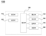
도 3은 본 발명의 일 실시 예에 따른 전압 가변형 온열 장치의 구성요소가 도시된 블록도이다.
도 4는 본 발명의 일 실시 예에 따른 전압 가변형 온열 장치의 통신부의 회로를 도시한 도면이다.
도 5는 본 발명의 일 실시 예에 따른 전압 가변형 온열 장치가 접혀진 상태를 도시한 도면이다.
도 6는 본 발명의 다른 실시 예에 따른 전압 가변형 온열 장치가 의자에 설치된 상태를 도시한 도면이다.1 is a diagram illustrating a voltage variable heating device, a battery device, and a power cable according to an embodiment of the present invention.
2 is a diagram illustrating an upper portion of a voltage variable type heating device according to an embodiment of the present invention.
3 is a block diagram illustrating components of a voltage variable heating device according to an embodiment of the present invention.
4 is a diagram illustrating a circuit of a communication unit of a voltage variable type heating device according to an embodiment of the present invention.
5 is a view showing a folded state of the voltage variable heating device according to an embodiment of the present invention.
6 is a diagram illustrating a state in which a voltage variable heating device according to another embodiment of the present invention is installed in a chair.
이하, 본 발명의 다양한 실시 예가 첨부된 도면을 참조하여 기재된다. 그러나, 이는 본 발명을 특정한 실시 형 태에 대해 한정하려는 것이 아니며, 본 발명의 실시 예의 다양한 변경(modification), 균등물(equivalent), 및/ 또는 대체물(alternative)을 포함하는 것으로 이해되어야 한다. 도면의 설명과 관련하여, 유사한 구성요소에 대 해서는 유사한 참조 부호가 사용될 수 있다. Hereinafter, various embodiments of the present invention will be described with reference to the accompanying drawings. However, this is not intended to limit the present invention to specific embodiments, and it should be understood that various modifications, equivalents, and/or alternatives of the embodiments of the present invention are included. In connection with the description of the drawings, like reference numerals may be used for like elements.
본 문서에서, "가진다", "가질 수 있다", "포함한다", 또는 "포함할 수 있다" 등의 표현은 해당 특징(예: 수치, 기능, 동작, 또는 부품 등의 구성요소)의 존재를 가리키며, 추가적인 특징의 존재를 배제하지 않는다. In this document, expressions such as "have", "may have", "includes", or "may include" refer to the presence of a corresponding characteristic (eg, a numerical value, function, operation, or component such as a part). and does not exclude the presence of additional features.
본 문서에서, "A 또는 B", "A 또는/및 B 중 적어도 하나", 또는 "A 또는/및 B 중 하나 또는 그 이상" 등의 표현 은 함께 나열된 항목들의 모든 가능한 조합을 포함할 수 있다. 예를 들면, "A 또는 B", "A 및 B 중 적어도 하나", 또는 "A 또는 B 중 적어도 하나"는, (1) 적어도 하나의 A를 포함, (2) 적어도 하나의 B를 포함, 또는(3) 적어도 하나의 A 및 적어도 하나의 B 모두를 포함하는 경우를 모두 지칭할 수 있다. In this document, expressions such as “A or B”, “at least one of A or/and B”, or “one or more of A or/and B” may include all possible combinations of the items listed together. . For example, "A or B", "at least one of A and B", or "at least one of A or B" means (1) includes at least one A, (2) includes at least one B; Or (3) it may refer to all cases including both at least one A and at least one B.
본 문서에서 사용된 "제1", "제2", "첫째", 또는 "둘째" 등의 표현들은 다양한 구성요소들을, 순서 및/또는 중 요도에 상관없이 수식할 수 있고, 한 구성요소를 다른 구성요소와 구분하기 위해 사용될 뿐 해당 구성요소들을 한정하지 않는다. 예를 들면, 제1 사용자 기기와 제2 사용자 기기는, 순서 또는 중요도와 무관하게, 서로 다른 사용자 기기를 나타낼 수 있다. 예를 들면, 본 문서에 기재된 권리 범위를 벗어나지 않으면서 제1 구성요소는 제2 구성요소로 명명될 수 있고, 유사하게 제2 구성요소도 제1 구성요소로 바꾸어 명명될 수 있다.Expressions such as "first", "second", "first", or "second" used in this document may modify various elements, regardless of order and/or importance, and may modify one element. It is used only to distinguish it from other components, and does not limit the components. For example, the first user equipment and the second user equipment may represent different user equipment regardless of order or importance. For example, without departing from the scope of the rights described in this document, a first component may be referred to as a second component, and similarly, the second component may also be renamed as a first component.
어떤 구성요소(예: 제1 구성요소)가 다른 구성요소(예: 제2 구성요소)에 "(기능적으로 또는 통신적으로) 연결되어((operatively or communicatively) coupled with/to)" 있다거나 "접속되어(connected to)" 있다고 언급된 때에는, 상기 어떤 구성요소가 상기 다른 구성요소에 직접적으로 연결되거나, 다른 구성요소(예: 제3 구성요소)를 통하여 연결될 수 있다고 이해되어야 할 것이다. 반면에, 어떤 구성요소(예: 제1 구성요소)가 다른 구성 요소(예: 제2 구성요소)에 "직접 연결되어" 있다거나 "직접 접속되어" 있다고 언급된 때에는, 상기 어떤 구성요소와 상기 다른 구성요소 사이에 다른 구성요소(예: 제3 구성요소)가 존재하지 않는 것으로 이해될 수 있다. A component (eg, a first component) is "coupled with/to (operatively or communicatively)" to another component (eg, a second component) When referring to "connected to", it will be understood that the certain element may be directly connected to the other element or may be connected through another element (eg, a third element). On the other hand, when it is said that a component (eg, a first component) is "directly connected" or "directly connected" to another component (eg, a second component), the component and the It may be understood that other components (eg, a third component) do not exist between other components.
본 문서에서 사용된 표현 "~하도록 구성된(또는 설정된)(configured to)"은 상황에 따라, 예를 들면, "~에 적합 한(suitable for)", "~하는 능력을 가지는(having the capacity to)", "~하도록 설계된(designed to)", "~하도록 변경된(adapted to)", "~하도록 만들어진(made to)", 또는 "~를 할 수 있는(capable of)"과 바꾸어 사용될 수 있다. 용어 "~하도록 구성(또는 설정)된"은 하드웨어적으로 "특별히 설계된(specifically designed to)"것만을 반드시 의미하지 않을 수 있다. 대신, 어떤 상황에서, "~하도록 구성된 장치"라는 표현은, 그 장치가 다른 장치 또는 부품들과 함께 "~할 수 있는" 것을 의미할 수 있다. 예를 들면, 문구 "A, B, 및 C를 수행하도록 구성 (또는 설정)된 제어부"는 해당 동작을 수행하기 위한 전용 프로세서(예: 임베디드 프로세서), 또는 메모리에 저장된 하나 이상의 소프트웨어 프로그램들을 실행함으로써, 해당 동작들을 수행할 수 있는 범용 프로세서(generic-purpose processor)(예: CPU 또는 application processor)를 의미할 수 있다. 여기서, 프로세서는 제어부를 의미할 수 있다.The expression “configured to (or configured to)” as used in this document, depending on the context, for example, “suitable for”, “having the capacity to )", "designed to", "adapted to", "made to", or "capable of" . The term “configured (or set up to)” may not necessarily mean only “specifically designed to” hardware. Instead, in some contexts, the expression “a device configured to” may mean that the device is “capable of” with other devices or parts. For example, the phrase "controller configured (or configured to perform) A, B, and C" may refer to a dedicated processor (eg, an embedded processor) for performing the corresponding operation, or by executing one or more software programs stored in memory. , may mean a generic-purpose processor (eg, a CPU or an application processor) capable of performing corresponding operations. Here, the processor may mean a control unit.
본 문서에서 사용된 용어들은 단지 특정한 실시 예를 설명하기 위해 사용된 것으로, 다른 실시 예의 범위를 한 정하려는 의도가 아닐 수 있다. 단수의 표현은 컨텍스트 상 명백하게 다르게 뜻하지 않는 한, 복수의 표현을 포함할 수 있다. 기술적이거나 과학적인 용어를 포함해서 여기서 사용되는 용어들은 본 문서에 기재된 기술 분야에서 통상의 지식을 가진 자에 의해 일반적으로 이해되는 것과 동일한 의미를 가질 수 있다. 본 문서에 사용된 용어들 중 일반적인 사전에 정의된 용어들은 관련 기술의 컨텍스트 상 가지는 의미와 동일 또는 유사한 의미로 해석될 수 있으며, 본 문서에서 명백하게 정의되지 않는 한, 이상적이거나 과도하게 형식적인 의미로 해석되지 않는다. 경우에 따라서, 본 문서에서 정의된 용어일지라도 본 문서의 실시 예들을 배제하도록 해석될 수 없다. Terms used in this document are only used to describe specific embodiments, and may not be intended to limit the scope of other embodiments. The singular expression may include the plural expression unless the context clearly dictates otherwise. Terms used herein, including technical or scientific terms, may have the same meanings as commonly understood by one of ordinary skill in the art described in this document. Among the terms used in this document, terms defined in general dictionary may be interpreted with the same or similar meaning to the meaning in the context of the related art, and unless explicitly defined in this document, have an ideal or excessively formal meaning. not interpreted In some cases, even terms defined in this document cannot be construed to exclude embodiments of this document.
도 1은 본 발명의 일 실시 예에 따른 전압 가변형 온열 장치, 배터리 장치 및 전원 케이블을 도시한 도면이고, 도 2는 본 발명의 일 실시 예에 따른 전압 가변형 온열 장치의 상부를 도시한 도면이고, 도 3은 본 발명의 일 실시 예에 따른 전압 가변형 온열 장치의 구성요소가 도시된 블록도이고, 도 4는 본 발명의 일 실시 예에 따른 전압 가변형 온열 장치의 통신부의 회로를 도시한 도면이고, 도 5는 본 발명의 일 실시 예에 따른 전압 가변형 온열 장치가 접혀진 상태를 도시한 도면이고, 도 6는 본 발명의 다른 실시 예에 따른 전압 가변형 온열 장치가 의자에 설치된 상태를 도시한 도면이다.1 is a diagram illustrating a voltage variable heating device, a battery device, and a power cable according to an embodiment of the present invention, and FIG. 2 is a diagram showing an upper portion of the voltage variable heating device according to an embodiment of the present invention; 3 is a block diagram illustrating components of a voltage variable heating device according to an embodiment of the present invention, and FIG. 4 is a diagram showing a circuit of a communication unit of the voltage variable heating device according to an embodiment of the present invention; 5 is a diagram illustrating a folded state of the voltage variable heating device according to an embodiment of the present invention, and FIG. 6 is a diagram illustrating a state in which the voltage variable heating device according to another embodiment of the present invention is installed in a chair.
도 1 내지 도 6을 참조하면, 본 발명의 일 실시 예에 따른 전압 가변형 온열 장치(100)는 외피부(110), 보온부(120), 발열부(130), 통신부(140), 제어부(150), 표시부(160), 입력부(170) 및 저장부(180)를 포함할 수 있다.1 to 6 , the voltage
본 발명의 일 실시 예에 따른 전압 가변형 온열 장치(100)는 전원 케이블(20)을 통해 배터리 장치(10)와 전기적으로 연결되어, 배터리 장치(10)에서 출력되는 출력 전압을 입력받아 열을 발생시킬 수 있다.The voltage
이를 위해, 본 발명의 일 실시 예에 따른 전압 가변형 온열 장치(100)는 배터리 장치(10)와 미리 정해진 전력 송수신 방식으로 전력을 송수신하고 미리 정해진 통신 방식으로 정보를 송수신할 수 있다. 예를 들어, 본 발명의 일 실시 예에 따른 전압 가변형 온열 장치(100)는 USB(Universal Serial Bus) 방식을 이용하여 배터리 장치(10)와 전력을 송수신하고 정보를 송수신할 수 있다.To this end, the voltage
외피부(110)는 직사각 플레이트 형상으로 형성되고, 전면과 배면이 접합되어 형성되며, 전면에 사용자가 착석하거나 전면이 사용자의 신체에 접촉될 수 있다.The
이러한, 외피부(110)는 열전도성이 좋은 섬유 소재로 형성될 수 있으나, 소재의 종류가 제한되지 않음을 유의한다. Note that the
이러한, 외피부(110)는 전면과 배면이 접한 지점 중 적어도 일부가 개폐되어 내부에 보온부(120) 및 발열부(130)를 수용할 수 있다.At least a portion of the
이를 위해, 외피부(110)는 제1 접힘영역(111) 및 제2 접힘영역(112)을 구비할 수 있다.To this end, the
제1 접힘영역(111)은 일측 모서리에서부터 타측 모서리까지 연장되어 형성될 수 있으며, 주위의 외피부(110)보다 함몰되어 형성될 수 있다.The first folded
제2 접힘영역(112)은 제1 접힘영역(111)과 이격 및 평행되어 형성되며 측 모서리에서부터 타측 모서리까지 연장되어 형성될 수 있고, 주위의 외피부(110)보다 함몰되어 형성될 수 있다.The second folded
이를 통해, 외피부(110)가 굴곡진 신체에 접하는 경우, 제1 접힘영역(111)과 제2 접힘영역(112)에 의해 신체 굴곡에 따라 외피부(110)가 원할하게 구부러져 신체와 외피부(110) 간이 밀착되어 접촉될 수 있다.Through this, when the
또한, 외피부(110)는 보관하기 용이하도록 제1 접힘영역(111)과 제2 접힘영역(112)에 의해 접혀질 수 있다.In addition, the
또한, 외피부(110')는 두개의 영역으로 나뉘어져 의자(C)에 설치됨으로써, 제1 영역은 사용자의 엉덩이에 접촉되면, 다른 제2 영역은 사용자의 등 부위에 접촉될 수 있다.In addition, the
보온부(120)는 외피부(110) 내측에 배치되고, 발열부(130)를 둘러싸 발열부(130)로부터 발생된 열을 흡수하여 다시 방출할 수 있다.The heat-retaining
이를 위해, 보온부(120)는 충진재를 구비할 수 있다. 충진재는 빠른 가열시간이나 열의 방출시간을 위해 전도율이 높고, 장기간 사용을 위해 보온성이 높은 소재로 구성될 수 있다.To this end, the
발열부(130)는 외피부(110)의 내측에 배치되고, 전력을 공급받아 열을 발생시킬 수 있다.The heating unit 130 may be disposed inside the
구체적으로, 발열부(130)는 배터리 장치(10)로부터 입력되는 출력 전력을 입력받아 열을 발생시킬 수 있다.Specifically, the heat generating unit 130 may generate heat by receiving output power input from the
이를 위해, 발열부(130)는 복수의 발열체를 구비할 수 있으며, 복수의 발열체는 구리 발열체 및 탄소 발열체 중 하나 이상이 첨가된 전도성 물질로 형성될 수 있다. To this end, the heating unit 130 may include a plurality of heating elements, and the plurality of heating elements may be formed of a conductive material to which at least one of a copper heating element and a carbon heating element is added.
여기서, 탄소 발열체는 우레탄, 실리콘 등 고무 계열의 베이스 물질에 탄소섬유, 카본블랙, 탄소펠트, 탄소봉, 탄소나노튜브 및 그래핀 중 하나 이상을 포함할 수 있다.Here, the carbon heating element may include one or more of carbon fibers, carbon black, carbon felt, carbon rods, carbon nanotubes, and graphene in a rubber-based base material such as urethane and silicone.
발열부(130)는 복수의 발열체 각각이 전기적으로 분리되도록 구성될 수도 있으며, 복수의 발열체가 전기적으로 연결되도록 구성될 수도 있다.The heating unit 130 may be configured such that each of the plurality of heating elements is electrically separated, or configured such that the plurality of heating elements are electrically connected.
이에 따라, 복수의 발열체 각각이 전기적으로 분리된 경우, 복수의 발열체 각각에는 출력 전력이 개별적으로 공급되고, 복수의 발열체가 전기적으로 연결된 경우, 복수의 발열체에는 동일한 출력 전력이 공급될 수 있다.Accordingly, when each of the plurality of heating elements is electrically separated, output power is individually supplied to each of the plurality of heating elements, and when the plurality of heating elements are electrically connected, the same output power may be supplied to the plurality of heating elements.
이러한, 발열부(130)는 복수의 발열체 각각의 전기적 연결 구성에 따라 발열을 위해 요구되는 요구 전압이 상이할 수 있다. The heating unit 130 may have a different required voltage for heating according to the electrical connection configuration of each of the plurality of heating elements.
통신부(140)는 제어부(150)의 제어를 받아 배터리 장치(10)로 신호를 송신할 수 있다. 여기서, 신호는 미리 정해진 직류 전압을 갖는 펄스 신호일 수 있다. The
구체적으로, 통신부(140)는 제어부(150)의 제어에 대응하여 출력 요청 신호를 배터리 장치(10)로 송신할 수 있다.Specifically, the
도 4에 도시된 바와 같이, 통신부(140)는 펄스 발생기(141), 제1 신호 출력 단자(142), 제2 신호 출력 단자(142'), 제1 하이 펄스 입력 단자(143), 제1 로우 펄스 입력 단자(144), 제2 하이 펄스 입력 단자(143') 및 제2 로우 펄스 입력 단자(144')를 구비할 수 있다.4 , the
펄스 발생기(141)는 제어부(150)의 제어에 따라 제1 하이 펄스 입력 단자(143), 제1 로우 펄스 입력 단자(144), 제2 하이 펄스 입력 단자(143') 및 제2 로우 펄스 입력 단자(144')에 온 펄스 신호 또는 로우 펄스 신호를 출력할 수 있다.The
제1 신호 출력 단자(142) 및 제2 신호 출력 단자(142')는 배터리 장치와 일단이 전기적으로 연결될 수 있다. 이러한, 제1 신호 출력 단자(142) 및 제2 신호 출력 단자(142')는 출력 요청 신호를 배터리 장치로 출력 및 송신할 수 있다.One end of the first
구체적으로, 제1 신호 출력 단자(142)는 제1 하이 펄스 입력 단자(143) 및 제1 로우 펄스 입력 단자(144)에 각각에 입력되는 펄스 신호에 따라 제1 내지 제3 플러스 신호를 출력할 수 있다.Specifically, the first
또한, 제2 신호 출력 단자(142')는 제2 하이 펄스 입력 단자(143') 및 제2 로우 펄스 입력 단자(144')에 각각에 입력되는 펄스 신호에 따라 제1 내지 제3 마이너스 신호를 출력할 수 있다.In addition, the second signal output terminal 142' receives the first to third minus signals according to the pulse signals input to the second high pulse input terminal 143' and the second low pulse input terminal 144', respectively. can be printed out.
제1 신호 출력 단자(142) 및 제2 신호 출력 단자(142') 각각에서 출력되는 제1 내지 제3 플러스 신호 및 제1 내지 제3 마이너스 신호가 상술된 출력 요청 신호를 구성할 수 있다.The first to third plus signals and the first to third minus signals output from each of the first
여기서, 제1 내지 제3 플러스 신호는 각각 0V, 0.6V, 3.3V의 전압을 갖는 신호일 수 있으며, 제1 내지 제3 마이너스 신호는 각각 0V, 0.6V, 3.3V의 전압을 갖는 신호일 수 있다.Here, the first to third plus signals may be signals having voltages of 0V, 0.6V, and 3.3V, respectively, and the first to third minus signals may be signals having voltages of 0V, 0.6V, and 3.3V, respectively.
제1 하이 펄스 입력 단자(143) 및 제1 로우 펄스 입력 단자(144)는 제1 신호 출력 단자(142)의 타단과 일단이 연결되고, 펄스 발생기(141)와 타단이 연결될 수 있다. The other end and one end of the first high
또한, 제1 하이 펄스 입력 단자(143) 및 제1 로우 펄스 입력 단자(144) 각각의 일단 사이에는 제1 하이 저항(145)과 제1 로우 저항(146)이 직렬로 연결되고, 제1 하이 저항(145)과 제1 로우 저항(146) 사이에는 제1 신호 출력 단자(142)가 연결될 수 있다. 제1 하이 저항(145)과 제1 로우 저항(146)은 제1 하이 펄스 입력 단자(143) 및 제1 로우 펄스 입력 단자(144)에서 제1 신호 출력 단자(142)로 출력되는 신호의 전압을 분해하는 역할을 수행할 수 있다.In addition, a first
제1 하이 펄스 입력 단자(143) 및 제1 로우 펄스 입력 단자(144)는 펄스 발생기(141)로부터 온 펄스 신호 또는 오프 펄스 신호를 입력받아 제1 신호 출력 단자(142)로 출력할 수 있다.The first high
이때, 제1 하이 펄스 입력 단자(143)에 온 펄스 신호가 입력되고, 제1 로우 펄스 입력 단자(144)에 온 펄스 신호가 입력되면, 제1 신호 출력 단자(142)는 제3 플러스 신호를 출력할 수 있다.At this time, when an on pulse signal is input to the first high
또한, 제1 하이 펄스 입력 단자(143)에 온 펄스 신호가 입력되고, 제1 로우 펄스 입력 단자(144)에 오프 펄스 신호가 입력되면, 제1 신호 출력 단자(142)는 제2 플러스 신호를 출력할 수 있다.Also, when an on pulse signal is input to the first high
또한, 제1 하이 펄스 입력 단자(143)에 오프 펄스 신호가 입력되고, 제1 로우 펄스 입력 단자(144)에 오프 펄스 신호가 입력되면, 제1 신호 출력 단자(142)는 제1 플러스 신호를 출력할 수 있다.In addition, when an off pulse signal is input to the first high
제2 하이 펄스 입력 단자(143') 및 제2 로우 펄스 입력 단자(144')는 제2 신호 출력 단자(142')의 타단과 일단이 연결되고, 펄스 발생기(141)와 타단이 연결될 수 있다.The second high
또한, 제2 하이 펄스 입력 단자(143') 및 제2 로우 펄스 입력 단자(144') 각각의 일단 사이에는 제2 하이 저항(145')과 제2 로우 저항(146')이 직렬로 연결되고, 제2 하이 저항(145')과 제2 로우 저항(146') 사이에는 제2 신호 출력 단자(142')가 연결될 수 있다. 제2 하이 저항(145')과 제2 로우 저항(146')은 제2 하이 펄스 입력 단자(143') 및 제2 로우 펄스 입력 단자(144')에서 제2 신호 출력 단자(142')로 출력되는 신호의 전압을 분해하는 역할을 수행할 수 있다.In addition, a second high resistor 145' and a second low resistor 146' are connected in series between one end of each of the second high pulse input terminal 143' and the second low pulse input terminal 144', , a second
제2 하이 펄스 입력 단자(143') 및 제2 로우 펄스 입력 단자(144')는 펄스 발생기(141)로부터 온 펄스 신호 또는 오프 펄스 신호를 입력받아 제2 신호 출력 단자(142')로 출력할 수 있다.The second high
이때, 제2 하이 펄스 입력 단자(143')에 온 펄스 신호가 입력되고, 제2 로우 펄스 입력 단자(144')에 온 펄스 신호가 입력되면, 제2 신호 출력 단자(142')는 제3 마이너스 신호를 출력할 수 있다.At this time, when the on pulse signal is input to the second high
또한, 제2 하이 펄스 입력 단자(143')에 온 펄스 신호가 입력되고, 제2 로우 펄스 입력 단자(144')에 오프 펄스 신호가 입력되면, 제2 신호 출력 단자(142')는 제2 마이너스 신호를 출력할 수 있다.Also, when an on pulse signal is input to the second high
또한, 제2 하이 펄스 입력 단자(143')에 오프 펄스 신호가 입력되고, 제2 로우 펄스 입력 단자(144')에 오프 펄스 신호가 입력되면, 제2 신호 출력 단자(142')는 제1 마이너스 신호를 출력할 수 있다.In addition, when an off pulse signal is input to the second high
한편, 제1 신호 출력 단자(142)에서 제3 플러스 신호가 배터리 장치로 출력되고, 제2 신호 출력 단자(142')에서 제2 마이너스 신호가 배터리 장치로 출력되면, 배터리 장치는 제1 전압에 대응하는 출력 전력을 출력할 수 있다.On the other hand, when a third plus signal is output from the first
또한, 제1 신호 출력 단자(142)에서 제2 플러스 신호가 배터리 장치로 출력되고, 제2 신호 출력 단자(142')에서 제2 마이너스 신호가 배터리 장치로 출력되면, 배터리 장치는 제2 전압에 대응하는 출력 전력을 출력할 수 있다.In addition, when a second positive signal is output from the first
또한, 제1 신호 출력 단자(142)에서 제3 플러스 신호가 배터리 장치로 출력되고, 제2 신호 출력 단자(142')에서 제3 마이너스 신호가 배터리 장치로 출력되면, 배터리 장치는 제3 전압에 대응하는 출력 전력을 출력할 수 있다.In addition, when a third plus signal is output from the first
여기서, 제1 내지 제3 전압은 각각 9V, 12V 및 20V일 수 있다.Here, the first to third voltages may be 9V, 12V, and 20V, respectively.
한편, 제어부(150)는 발열부의 요구 전압 정보에 대응되는 전압이 제1 전압이면, 제1 하이 펄스 입력 단자(143)에 온 펄스 신호가 입력되고, 제1 로우 펄스 입력 단자(144)에 온 펄스 신호가 입력되고, 제2 하이 펄스 입력 단자(143')에 온 펄스 신호가 입력되고, 제2 로우 펄스 입력 단자(144')에 오프 펄스 신호가 입력되도록 펄스 발생기(141)를 제어할 수 있다.On the other hand, when the voltage corresponding to the requested voltage information of the heating unit is the first voltage, the
또한, 제어부(150)는 발열부의 요구 전압 정보에 대응되는 전압이 제2 전압이면, 제1 하이 펄스 입력 단자(143)에 온 펄스 신호가 입력되고, 제1 로우 펄스 입력 단자(144)에 오프 펄스 신호가 입력되고, 제2 하이 펄스 입력 단자(143')에 온 펄스 신호가 입력되고, 제2 로우 펄스 입력 단자(144')에 오프 펄스 신호가 입력되도록 펄스 발생기(141)를 제어할 수 있다.In addition, when the voltage corresponding to the requested voltage information of the heating unit is the second voltage, the
또한, 제어부(150)는 발열부의 요구 전압 정보에 대응되는 전압이 제3 전압이면, 제1 하이 펄스 입력 단자(143)에 온 펄스 신호가 입력되고, 제1 로우 펄스 입력 단자(144)에 온 펄스 신호가 입력되고, 제2 하이 펄스 입력 단자(143')에 온 펄스 신호가 입력되고, 제2 로우 펄스 입력 단자(144')에 온 펄스 신호가 입력되도록 펄스 발생기(141)를 제어할 수 있다. In addition, when the voltage corresponding to the requested voltage information of the heating unit is the third voltage, the
제어부(150)는 발열부(130)의 요구 전압 정보에 대응되는 출력 전력을 요청하는 출력 요청 신호를 배터리 장치(10)로 송신하도록 통신부(140)를 제어할 수 있다.The
구체적으로, 제어부(150)는 발열부(130)의 미리 설정된 요구 전압 정보가 나타내는 요구 전압과 동일한 출력 전압의 출력 전력이 배터리 장치(10)로부터 출력되도록하는 출력 요청 신호를 배터리 장치(10)로 송신하도록 통신부(140)를 제어할 수 있다.Specifically, the
이때, 펄스 신호의 직류 전압 범위 마다 출력 전압이 설정될 수 있고, 제어부(150)는 요구 전압과 동일한 출력 전압이 설정된 직류 전압 범위 내의 직류 전압에 따른 펄스 신호가 출력 요청 신호로써 출력 되도록 통신부(140)를 제어할 수 있다.At this time, an output voltage may be set for each DC voltage range of the pulse signal, and the
예를 들어, 요구 전압이 9V이고, 출력 전압 9V가 설정된 펄스 신호의 직류 전압 범위가 1V 내지 1.5V인 경우, 제어부(150)는 출력 요청 신호로써 1V 내지 1.5V 내에 포함되는 직류 전압의 펄스 신호가 출력 되도록 통신부(140)를 제어할 수 있다.For example, when the required voltage is 9V and the DC voltage range of the pulse signal to which the output voltage of 9V is set is 1V to 1.5V, the
이후, 배터리 장치(10)는 1V 내지 1.5V 내에 포함되는 직류 전압의 펄스 신호가 입력되면 직류 전압 범위가 1V 내지 1.5V의 직류 전압 범위에 설정된 출력 전압 9V의 출력 전력을 출력할 수 있다.Thereafter, when a pulse signal of a DC voltage included in 1V to 1.5V is input, the
한편, 제어부(150)는 배터리 장치(10)로부터 입력되는 출력 전력의 출력 전압과 요구 전압 정보에 대응되는 요구 전압 간의 전압차가 미리 설정된 기준 전압차 범위 내에 포함되는지 여부를 확인할 수 있다.Meanwhile, the
이후, 제어부(150)는 출력 전압과 요구 전압 간의 전압차가 미리 설정된 기준 전압차 범위 내에 포함되지 않으면, 출력 요청 신호를 재송신하도록 통신부(140)를 제어할 수 있다.Thereafter, when the voltage difference between the output voltage and the requested voltage is not included in a preset reference voltage difference range, the
이를 통해, 제어부(150)는 요구 전압과 동일한 출력 전압의 출력 전력이 배터리 장치(10)로부터 출력되도록 신호를 지속하여 송신할 수 있다.Through this, the
한편, 제어부(150)는 출력 요청 신호의 재송신 횟수 정보를 생성하고, 재송신 횟수 정보가 미리 설정된 기준 횟수를 초과하는지 여부를 확인할 수 있다.Meanwhile, the
이후, 제어부(150)는 재송신 횟수 정보가 미리 설정된 기준 횟수를 초과하면, 출력 전압이 요구 전압으로 가변되어 출력되지 않음을 나타내는 오류 발생 정보를 생성할 수 있다.Thereafter, when the retransmission number information exceeds a preset reference number, the
제어부(150)는 오류 발생 정보를 표시부(160)가 표시하도록 표시부(160)를 제어할 수 있다.The
이를 통해, 제어부(150)는 요구 전압과 동일한 출력 전압의 출력 전력이 출력되지 않아 전압 가변형 온열 장치(10)가 정상 작동되지 않음을 사용자에게 알릴 수 있다.Through this, the
한편, 다른 실시 예에 따른 제어부(150)는 발열부(130)의 제어 온도 정보, 발열부(130)의 발열 영역 정보 및 발열부(130)의 전기적 물리 특성 정보 중 하나 이상에 기초하여 요구 전압 정보를 생성할 수 있다.On the other hand, the
여기서, 제어 온도 정보는 발생되는 열의 목표 온도를 나타내는 정보이고, 발열 영역 정보는 복수의 영역(T1, …, T3)으로 구획된 발열부(130) 중에서 열을 발생하는 것으로 설정된 영역을 나타내는 정보이고, 전기적 물리 특성 정보는 발열부(130)의 정격 전압, 정격 전류 및 합성 저항을 나타내는 정보일 수 있다.Here, the control temperature information is information indicating a target temperature of generated heat, and the heating region information is information indicating a region set to generate heat among the heating unit 130 divided into a plurality of regions T1, ..., T3. , the electrical and physical characteristic information may be information indicating a rated voltage, a rated current, and a combined resistance of the heating unit 130 .
구체적으로, 다른 실시 예에 따른 제어부(150)는 발열부(130)의 제어 온도 정보, 발열부(130)의 발열 영역 정보 및 발열부(130)의 전기적 물리 특성 정보 중 하나 이상에 기초하여 발열부(130) 인가가 필요한 필요 전압을 산출하고, 배터리 장치(10)에서 출력 가능한 복수의 출력 가능 전압 중에서 필요 전압과의 전압차가 최소인 출력 가능 전압을 요구 전압을 결정할 수 있다. 이후, 다른 실시 예에 따른 제어부(150)는 결정된 요구 전압을 나타내는 요구 전압 정보를 생성할 수 있다.Specifically, the
이를 통해, 제어부(150)는 발열부(130)의 제어 온도, 전기적 물리 특성 및 발열 영역 중 하나 이상이 변경되어 요구되는 전압이 변경되는 경우에 대응하여 요구 전압 정보를 생성할 수 있다.Through this, the
표시부(160)는 전압 가변형 온열 장치의 작동 여부 정보, 발열부의 발열 온도 정보 및 오류 발생 정보를 표시할 수 있다. 이를 위해, 표시부(160)는 복수의 LED 모듈을 구비하여 빛으로 전압 가변형 온열 장치의 작동 여부 정보, 발열부의 발열 온도 정보 및 오류 발생 정보를 표시할 수 있다.The
입력부(170)는 사용자로부터 전원 온오프 정보, 제어 온도 정보 및 발열 영역 제어 정보를 입력받을 수 있다.The
구체적으로, 입력부(170)는 전압 가변형 온열 장치(100)의 전원 온오프 정보, 발열부(130)의 제어 온도 정보 및 발열부(130)의 발열 영역 제어 정보를 입력받을 수 있다.Specifically, the
이를 위해, 입력부(170)는 버튼 모듈 및 다이얼 모듈 중 하나 이상을 구비할 수 있다.To this end, the
한편, 전압 가변형 온열 장치(100)는 발열부(130)의 온도를 제어하기 위하여 발열부(130)의 온도를 측정하는 측정부를 더 포함할 수 있으며, 측정부는 온도센서를 구비할 수 있다.Meanwhile, the voltage
저장부(180)에는 제어부(150)의 처리 및 제어를 위한 프로그램들(하나 이상의 인스트럭션들)을 저장할 수 있다. 저장부(180)에 저장된 프로그램들은 기능에 따라 복수 개의 모듈들로 구분될 수 있다.The
이제까지 본 발명에 대하여 바람직한 실시 예를 중심으로 살펴보았다. 본 발명이 속하는 기술 분야에서 통상의 지식을 가진 자는 본 발명의 본질적인 특성에서 벗어나지 않는 범위에서 변형된 형태로 본 발명을 구현할 수 있음을 이해할 것이다. 그러므로 상기 개시된 실시 예들은 한정적인 관점이 아니라 설명적인 관점에서 고려되어야 한다. 본 발명의 범위는 전술한 설명이 아니라 특허청구범위에 나타나 있으며, 그와 동등한 범위 내에 있는 모든 차이점은 본 발명에 포함된 것으로 해석되어야 한다.So far, the present invention has been focused on preferred embodiments. Those of ordinary skill in the art to which the present invention pertains will understand that the present invention can be implemented in modified forms without departing from the essential characteristics of the present invention. Therefore, the disclosed embodiments should be considered in an illustrative rather than a restrictive point of view. The scope of the present invention is indicated in the claims rather than the foregoing description, and all differences within an equivalent scope should be construed as being included in the present invention.
이상과 같이, 본 발명은 비록 한정된 실시 예와 도면에 의해 설명되었으나, 본 발명은 이것에 의해 한정되지 않으며 본 발명이 속하는 기술분야에서 통상의 지식을 가진 자에 의해 본 발명의 기술사상과 아래에 기재될 특허청구범위의 균등범위 내에서 다양한 수정 및 변형이 가능함은 물론이다.As described above, although the present invention has been described with reference to limited embodiments and drawings, the present invention is not limited thereto, and the technical idea of the present invention and the following by those of ordinary skill in the art to which the present invention pertains. Of course, various modifications and variations are possible within the scope of equivalents of the claims to be described.
100: 전압 가변형 온열 장치
110: 외피부
120: 보온부
130: 발열부
140: 통신부
150: 제어부
160: 표시부
170: 입력부
180: 저장부100: voltage variable heating device
110: outer skin
120: warming unit
130: heating part
140: communication department
150: control unit
160: display unit
170: input unit
180: storage
Claims (9)
직사각 플레이트 형상으로 형성되고, 전면과 배면이 접합되어 형성되며, 상기 전면에 사용자가 착석하거나 상기 전면이 사용자의 신체에 접촉되는 외피부;
상기 외피부 내측에 배치되고, 열을 발생시키는 발열부;
상기 배터리 장치로 신호를 송신하는 통신부; 및
상기 발열부의 요구 전압 정보에 대응되는 출력 전력을 요청하는 출력 요청 신호를 상기 배터리 장치로 송신하도록 상기 통신부를 제어하는 제어부;를 포함하며,
상기 통신부는
펄스를 발생시키는 펄스 발생기;
상기 배터리 장치와 일단이 전기적으로 연결되는 제1 신호 출력 단자 및 제2 신호 출력 단자;
제1 신호 입력 단자의 타단과 일단이 연결되고, 상기 펄스 발생기와 타단이 연결되는 제1 하이 펄스 입력 단자(143) 및 제1 로우 펄스 입력 단자(144); 및
제2 신호 입력 단자의 타단과 일단이 연결되고, 상기 펄스 발생기와 타단이 연결되는 제2 하이 펄스 입력 단자(143') 및 제2 로우 펄스 입력 단자;를 구비하는 것을 특징으로 하는
전압 가변형 온열 장치.
A voltage variable heating device for generating heat by receiving output power output from a battery device,
It is formed in the shape of a rectangular plate, the front and the rear are joined to form an outer skin that the user sits on the front or the front is in contact with the user's body;
a heating part disposed inside the outer skin and generating heat;
a communication unit for transmitting a signal to the battery device; and
a control unit for controlling the communication unit to transmit an output request signal for requesting output power corresponding to the requested voltage information of the heating unit to the battery device;
the communication unit
a pulse generator for generating pulses;
a first signal output terminal and a second signal output terminal electrically connected to the battery device at one end;
a first high pulse input terminal 143 and a first low pulse input terminal 144 connected to the other end and one end of the first signal input terminal and connected to the pulse generator and the other end; and
and a second high pulse input terminal 143' and a second low pulse input terminal connected to the other end and one end of the second signal input terminal, and connected to the pulse generator and the other end.
Voltage variable thermostat.
상기 제어부는
상기 발열부의 요구 전압 정보에 대응되는 전압이 제1 전압이면, 제1 하이 펄스 입력 단자(143)에 온 펄스 신호가 입력되고, 제1 로우 펄스 입력 단자(144)에 온 펄스 신호가 입력되고, 제2 하이 펄스 입력 단자(143')에 온 펄스 신호가 입력되고, 제2 로우 펄스 입력 단자에 오프 펄스 신호가 입력되도록 상기 펄스 발생기를 제어하는 것을 특징으로 하는
전압 가변형 온열 장치.
According to claim 1,
the control unit
When the voltage corresponding to the requested voltage information of the heating unit is the first voltage, an on pulse signal is input to the first high pulse input terminal 143 and an on pulse signal is input to the first low pulse input terminal 144 , Controlling the pulse generator so that an on pulse signal is input to a second high pulse input terminal (143') and an off pulse signal is input to a second low pulse input terminal (143')
Voltage variable thermostat.
상기 제어부는
상기 발열부의 요구 전압 정보에 대응되는 전압이 제2 전압이면, 제1 하이 펄스 입력 단자(143)에 온 펄스 신호가 입력되고, 제1 로우 펄스 입력 단자(144)에 오프 펄스 신호가 입력되고, 제2 하이 펄스 입력 단자(143')에 온 펄스 신호가 입력되고, 제2 로우 펄스 입력 단자에 오프 펄스 신호가 입력되도록 상기 펄스 발생기를 제어하는 것을 특징으로 하는
전압 가변형 온열 장치.
According to claim 1,
the control unit
When the voltage corresponding to the requested voltage information of the heating unit is the second voltage, an on pulse signal is input to the first high pulse input terminal 143 and an off pulse signal is input to the first low pulse input terminal 144 , Controlling the pulse generator so that an on pulse signal is input to a second high pulse input terminal (143') and an off pulse signal is input to a second low pulse input terminal (143')
Voltage variable thermostat.
상기 제어부는
상기 발열부의 요구 전압 정보에 대응되는 전압이 제3 전압이면, 제1 하이 펄스 입력 단자(143)에 온 펄스 신호가 입력되고, 제1 로우 펄스 입력 단자(144)에 온 펄스 신호가 입력되고, 제2 하이 펄스 입력 단자(143')에 온 펄스 신호가 입력되고, 제2 로우 펄스 입력 단자에 온 펄스 신호가 입력되도록 상기 펄스 발생기를 제어하는 것을 특징으로 하는
전압 가변형 온열 장치.
According to claim 1,
the control unit
When the voltage corresponding to the requested voltage information of the heating unit is the third voltage, the on pulse signal is input to the first high pulse input terminal 143 and the on pulse signal is input to the first low pulse input terminal 144 , Controlling the pulse generator so that an on pulse signal is input to a second high pulse input terminal (143') and an on pulse signal is input to a second low pulse input terminal
Voltage variable thermostat.
상기 제어부는
상기 배터리 장치로부터 입력되는 상기 출력 전력의 출력 전압과 상기 요구 전압 정보에 대응되는 요구 전압 간의 전압차가 미리 설정된 기준 전압차 범위 내에 포함되는지 여부를 확인하고, 상기 출력 전압과 상기 요구 전압 간의 전압차가 상기 미리 설정된 기준 전압차 범위 내에 포함되지 않으면, 상기 출력 요청 신호를 재송신하도록 상기 통신부를 제어하는 것을 특징으로 하는
전압 가변형 온열 장치.
According to claim 1,
the control unit
It is checked whether a voltage difference between the output voltage of the output power input from the battery device and the required voltage corresponding to the requested voltage information is included within a preset reference voltage difference range, and the voltage difference between the output voltage and the requested voltage is the If not included within a preset reference voltage difference range, characterized in that for controlling the communication unit to retransmit the output request signal
Voltage variable thermostat.
상기 제어부는
상기 출력 요청 신호의 재송신 횟수 정보를 생성하고, 상기 재송신 횟수 정보가 미리 설정된 기준 횟수를 초과하는지 여부를 확인하고, 상기 재송신 횟수 정보가 상기 미리 설정된 기준 횟수를 초과하면, 상기 출력 전압이 상기 요구 전압으로 가변되어 출력되지 않음을 나타내는 오류 발생 정보를 생성하는 것을 특징으로 하는
전압 가변형 온열 장치.
7. The method of claim 6,
the control unit
generating information on the number of times of retransmission of the output request signal, checking whether the information on the number of retransmissions exceeds a preset reference number and generating error occurrence information indicating that the output is not changed to
Voltage variable thermostat.
상기 전압 가변형 온열 장치의 작동 여부 정보, 상기 발열부의 발열 온도 정보 및 상기 오류 발생 정보를 표시하는 표시부;를 더 포함하는 것을 특징으로 하는
전압 가변형 온열 장치.
8. The method of claim 7,
and a display unit configured to display information on whether the voltage variable heating device operates, information on the heating temperature of the heating unit, and information on the occurrence of the error.
Voltage variable thermostat.
상기 제어부는
상기 발열부의 제어 온도 정보, 상기 발열부의 발열 영역 정보 및 상기 발열부의 전기적 물리 특성 정보 중 하나 이상에 기초하여 상기 요구 전압 정보를 생성하는 것을 특징으로 하는
전압 가변형 온열 장치.
According to claim 1,
the control unit
and generating the requested voltage information based on at least one of control temperature information of the heating unit, information on a heating region of the heating unit, and electrical and physical property information of the heating unit.
Voltage variable thermostat.
Priority Applications (1)
| Application Number | Priority Date | Filing Date | Title |
|---|---|---|---|
| KR1020200140148A KR102285175B1 (en) | 2020-10-27 | 2020-10-27 | Apparatus for heating using voltage variable |
Applications Claiming Priority (1)
| Application Number | Priority Date | Filing Date | Title |
|---|---|---|---|
| KR1020200140148A KR102285175B1 (en) | 2020-10-27 | 2020-10-27 | Apparatus for heating using voltage variable |
Publications (1)
| Publication Number | Publication Date |
|---|---|
| KR102285175B1 true KR102285175B1 (en) | 2021-08-03 |
Family
ID=77314344
Family Applications (1)
| Application Number | Title | Priority Date | Filing Date |
|---|---|---|---|
| KR1020200140148A Active KR102285175B1 (en) | 2020-10-27 | 2020-10-27 | Apparatus for heating using voltage variable |
Country Status (1)
| Country | Link |
|---|---|
| KR (1) | KR102285175B1 (en) |
Citations (4)
| Publication number | Priority date | Publication date | Assignee | Title |
|---|---|---|---|---|
| KR940001803Y1 (en) * | 1991-03-07 | 1994-03-24 | 박찬묵 | Temperature control apparatus in an electric blanket |
| KR970070802A (en) * | 1996-04-18 | 1997-11-07 | 이재구 | Bed thermostat |
| KR200347994Y1 (en) * | 2003-12-08 | 2004-04-28 | 주식회사 동아기전 | Portable pad apparatus utilizing string type heating emement and portable battery |
| KR200425335Y1 (en) | 2006-04-19 | 2006-09-06 | 정광식 | Portable Insulation Cushion Using Carbon Fiber |
-
2020
- 2020-10-27 KR KR1020200140148A patent/KR102285175B1/en active Active
Patent Citations (4)
| Publication number | Priority date | Publication date | Assignee | Title |
|---|---|---|---|---|
| KR940001803Y1 (en) * | 1991-03-07 | 1994-03-24 | 박찬묵 | Temperature control apparatus in an electric blanket |
| KR970070802A (en) * | 1996-04-18 | 1997-11-07 | 이재구 | Bed thermostat |
| KR200347994Y1 (en) * | 2003-12-08 | 2004-04-28 | 주식회사 동아기전 | Portable pad apparatus utilizing string type heating emement and portable battery |
| KR200425335Y1 (en) | 2006-04-19 | 2006-09-06 | 정광식 | Portable Insulation Cushion Using Carbon Fiber |
Similar Documents
| Publication | Publication Date | Title |
|---|---|---|
| CN105531869B (en) | battery cell assembly | |
| CN106576399A (en) | Radiation heating device | |
| KR101222772B1 (en) | Method and system for power controlling electric range having a large number of heater | |
| JP2008198407A (en) | Planar heating element | |
| KR102285175B1 (en) | Apparatus for heating using voltage variable | |
| KR200421908Y1 (en) | Versatile Hand Stove | |
| CN106104906B (en) | battery cell assembly | |
| US20210207815A1 (en) | Electric heating mat | |
| KR101569507B1 (en) | Electric mat having mat controller comprising electromagnetic wave shielding means | |
| US10244582B2 (en) | Self-regulating dual heating level heating element | |
| JP2010132055A (en) | Vehicle heater | |
| US20150120076A1 (en) | Electronic device having intelligent temperature adjusting function | |
| CN109429385B (en) | Sheath heater | |
| US20160278162A1 (en) | Vehicle heating system | |
| KR20190070215A (en) | Heater with parallel type heating cicuit and control method thereof | |
| KR101469062B1 (en) | Electric mat having means for shielding electromagnetic wave | |
| CN220017505U (en) | Driver circuit for portable heating device | |
| CN116830796A (en) | Power supply controller, heater system, power supply system and power supply method capable of supplying power to a planar heater | |
| CN214704448U (en) | Movable temperature controller | |
| KR101349363B1 (en) | Heating seat for vehicle | |
| KR200419916Y1 (en) | Heating mat with surface heating means | |
| CN210035668U (en) | High-temperature-resistant graphene electric heating wall painting | |
| KR100585193B1 (en) | Bidet sheet with thermal insulation | |
| CN207491223U (en) | Efficient and environmentally friendly electric energy heat generation and temperature control thin film system | |
| JPS63231894A (en) | Divided heat-sensitive panel heater |
Legal Events
| Date | Code | Title | Description |
|---|---|---|---|
| PA0109 | Patent application |
St.27 status event code: A-0-1-A10-A12-nap-PA0109 |
|
| PA0201 | Request for examination |
St.27 status event code: A-1-2-D10-D11-exm-PA0201 |
|
| PA0302 | Request for accelerated examination |
St.27 status event code: A-1-2-D10-D17-exm-PA0302 St.27 status event code: A-1-2-D10-D16-exm-PA0302 |
|
| D13-X000 | Search requested |
St.27 status event code: A-1-2-D10-D13-srh-X000 |
|
| D14-X000 | Search report completed |
St.27 status event code: A-1-2-D10-D14-srh-X000 |
|
| PE0902 | Notice of grounds for rejection |
St.27 status event code: A-1-2-D10-D21-exm-PE0902 |
|
| E13-X000 | Pre-grant limitation requested |
St.27 status event code: A-2-3-E10-E13-lim-X000 |
|
| P11-X000 | Amendment of application requested |
St.27 status event code: A-2-2-P10-P11-nap-X000 |
|
| P13-X000 | Application amended |
St.27 status event code: A-2-2-P10-P13-nap-X000 |
|
| E701 | Decision to grant or registration of patent right | ||
| PE0701 | Decision of registration |
St.27 status event code: A-1-2-D10-D22-exm-PE0701 |
|
| GRNT | Written decision to grant | ||
| PR0701 | Registration of establishment |
St.27 status event code: A-2-4-F10-F11-exm-PR0701 |
|
| PR1002 | Payment of registration fee |
St.27 status event code: A-2-2-U10-U11-oth-PR1002 Fee payment year number: 1 |
|
| PG1601 | Publication of registration |
St.27 status event code: A-4-4-Q10-Q13-nap-PG1601 |
|
| R18-X000 | Changes to party contact information recorded |
St.27 status event code: A-5-5-R10-R18-oth-X000 |
|
| PR1001 | Payment of annual fee |
St.27 status event code: A-4-4-U10-U11-oth-PR1001 Fee payment year number: 4 |
|
| PR1001 | Payment of annual fee |
St.27 status event code: A-4-4-U10-U11-oth-PR1001 Fee payment year number: 5 |
|
| P22-X000 | Classification modified |
St.27 status event code: A-4-4-P10-P22-nap-X000 |