KR102264701B1 - Rechargeable battery - Google Patents
Rechargeable battery Download PDFInfo
- Publication number
- KR102264701B1 KR102264701B1 KR1020160092249A KR20160092249A KR102264701B1 KR 102264701 B1 KR102264701 B1 KR 102264701B1 KR 1020160092249 A KR1020160092249 A KR 1020160092249A KR 20160092249 A KR20160092249 A KR 20160092249A KR 102264701 B1 KR102264701 B1 KR 102264701B1
- Authority
- KR
- South Korea
- Prior art keywords
- tab
- electrode
- uncoated
- secondary battery
- electrode assembly
- Prior art date
- Legal status (The legal status is an assumption and is not a legal conclusion. Google has not performed a legal analysis and makes no representation as to the accuracy of the status listed.)
- Active
Links
- 239000011248 coating agent Substances 0.000 claims abstract description 21
- 238000000576 coating method Methods 0.000 claims abstract description 21
- 239000011149 active material Substances 0.000 claims abstract description 19
- 238000000034 method Methods 0.000 claims 10
- 238000000926 separation method Methods 0.000 description 6
- 229910052751 metal Inorganic materials 0.000 description 3
- 239000002184 metal Substances 0.000 description 3
- 239000011230 binding agent Substances 0.000 description 2
- 239000004020 conductor Substances 0.000 description 2
- 238000007599 discharging Methods 0.000 description 2
- 230000000694 effects Effects 0.000 description 2
- 239000000463 material Substances 0.000 description 2
- 239000007769 metal material Substances 0.000 description 2
- -1 polyethylene Polymers 0.000 description 2
- 238000003466 welding Methods 0.000 description 2
- RYGMFSIKBFXOCR-UHFFFAOYSA-N Copper Chemical compound [Cu] RYGMFSIKBFXOCR-UHFFFAOYSA-N 0.000 description 1
- WHXSMMKQMYFTQS-UHFFFAOYSA-N Lithium Chemical compound [Li] WHXSMMKQMYFTQS-UHFFFAOYSA-N 0.000 description 1
- 239000004698 Polyethylene Substances 0.000 description 1
- 239000004743 Polypropylene Substances 0.000 description 1
- 230000002159 abnormal effect Effects 0.000 description 1
- 229910052782 aluminium Inorganic materials 0.000 description 1
- XAGFODPZIPBFFR-UHFFFAOYSA-N aluminium Chemical compound [Al] XAGFODPZIPBFFR-UHFFFAOYSA-N 0.000 description 1
- 239000003575 carbonaceous material Substances 0.000 description 1
- 229910052802 copper Inorganic materials 0.000 description 1
- 239000010949 copper Substances 0.000 description 1
- 239000003792 electrolyte Substances 0.000 description 1
- 230000004927 fusion Effects 0.000 description 1
- 239000012212 insulator Substances 0.000 description 1
- 235000015110 jellies Nutrition 0.000 description 1
- 239000008274 jelly Substances 0.000 description 1
- 229910052744 lithium Inorganic materials 0.000 description 1
- 238000012986 modification Methods 0.000 description 1
- 230000004048 modification Effects 0.000 description 1
- 239000007773 negative electrode material Substances 0.000 description 1
- 229920000573 polyethylene Polymers 0.000 description 1
- 229920000098 polyolefin Polymers 0.000 description 1
- 229920001155 polypropylene Polymers 0.000 description 1
- 239000011148 porous material Substances 0.000 description 1
- 230000001681 protective effect Effects 0.000 description 1
- 238000004080 punching Methods 0.000 description 1
- 230000008961 swelling Effects 0.000 description 1
Images


Classifications
-
- H—ELECTRICITY
- H01—ELECTRIC ELEMENTS
- H01M—PROCESSES OR MEANS, e.g. BATTERIES, FOR THE DIRECT CONVERSION OF CHEMICAL ENERGY INTO ELECTRICAL ENERGY
- H01M50/00—Constructional details or processes of manufacture of the non-active parts of electrochemical cells other than fuel cells, e.g. hybrid cells
- H01M50/50—Current conducting connections for cells or batteries
- H01M50/572—Means for preventing undesired use or discharge
-
- H—ELECTRICITY
- H01—ELECTRIC ELEMENTS
- H01M—PROCESSES OR MEANS, e.g. BATTERIES, FOR THE DIRECT CONVERSION OF CHEMICAL ENERGY INTO ELECTRICAL ENERGY
- H01M10/00—Secondary cells; Manufacture thereof
- H01M10/04—Construction or manufacture in general
- H01M10/0431—Cells with wound or folded electrodes
-
- H—ELECTRICITY
- H01—ELECTRIC ELEMENTS
- H01M—PROCESSES OR MEANS, e.g. BATTERIES, FOR THE DIRECT CONVERSION OF CHEMICAL ENERGY INTO ELECTRICAL ENERGY
- H01M10/00—Secondary cells; Manufacture thereof
- H01M10/05—Accumulators with non-aqueous electrolyte
- H01M10/052—Li-accumulators
-
- H—ELECTRICITY
- H01—ELECTRIC ELEMENTS
- H01M—PROCESSES OR MEANS, e.g. BATTERIES, FOR THE DIRECT CONVERSION OF CHEMICAL ENERGY INTO ELECTRICAL ENERGY
- H01M10/00—Secondary cells; Manufacture thereof
- H01M10/05—Accumulators with non-aqueous electrolyte
- H01M10/058—Construction or manufacture
- H01M10/0587—Construction or manufacture of accumulators having only wound construction elements, i.e. wound positive electrodes, wound negative electrodes and wound separators
-
- H—ELECTRICITY
- H01—ELECTRIC ELEMENTS
- H01M—PROCESSES OR MEANS, e.g. BATTERIES, FOR THE DIRECT CONVERSION OF CHEMICAL ENERGY INTO ELECTRICAL ENERGY
- H01M10/00—Secondary cells; Manufacture thereof
- H01M10/24—Alkaline accumulators
- H01M10/28—Construction or manufacture
- H01M10/281—Large cells or batteries with stacks of plate-like electrodes
-
- H—ELECTRICITY
- H01—ELECTRIC ELEMENTS
- H01M—PROCESSES OR MEANS, e.g. BATTERIES, FOR THE DIRECT CONVERSION OF CHEMICAL ENERGY INTO ELECTRICAL ENERGY
- H01M10/00—Secondary cells; Manufacture thereof
- H01M10/42—Methods or arrangements for servicing or maintenance of secondary cells or secondary half-cells
- H01M10/425—Structural combination with electronic components, e.g. electronic circuits integrated to the outside of the casing
-
- H—ELECTRICITY
- H01—ELECTRIC ELEMENTS
- H01M—PROCESSES OR MEANS, e.g. BATTERIES, FOR THE DIRECT CONVERSION OF CHEMICAL ENERGY INTO ELECTRICAL ENERGY
- H01M50/00—Constructional details or processes of manufacture of the non-active parts of electrochemical cells other than fuel cells, e.g. hybrid cells
- H01M50/50—Current conducting connections for cells or batteries
- H01M50/531—Electrode connections inside a battery casing
-
- H—ELECTRICITY
- H01—ELECTRIC ELEMENTS
- H01M—PROCESSES OR MEANS, e.g. BATTERIES, FOR THE DIRECT CONVERSION OF CHEMICAL ENERGY INTO ELECTRICAL ENERGY
- H01M50/00—Constructional details or processes of manufacture of the non-active parts of electrochemical cells other than fuel cells, e.g. hybrid cells
- H01M50/50—Current conducting connections for cells or batteries
- H01M50/531—Electrode connections inside a battery casing
- H01M50/54—Connection of several leads or tabs of plate-like electrode stacks, e.g. electrode pole straps or bridges
-
- H—ELECTRICITY
- H01—ELECTRIC ELEMENTS
- H01M—PROCESSES OR MEANS, e.g. BATTERIES, FOR THE DIRECT CONVERSION OF CHEMICAL ENERGY INTO ELECTRICAL ENERGY
- H01M50/00—Constructional details or processes of manufacture of the non-active parts of electrochemical cells other than fuel cells, e.g. hybrid cells
- H01M50/50—Current conducting connections for cells or batteries
- H01M50/572—Means for preventing undesired use or discharge
- H01M50/584—Means for preventing undesired use or discharge for preventing incorrect connections inside or outside the batteries
- H01M50/586—Means for preventing undesired use or discharge for preventing incorrect connections inside or outside the batteries inside the batteries, e.g. incorrect connections of electrodes
-
- H—ELECTRICITY
- H01—ELECTRIC ELEMENTS
- H01M—PROCESSES OR MEANS, e.g. BATTERIES, FOR THE DIRECT CONVERSION OF CHEMICAL ENERGY INTO ELECTRICAL ENERGY
- H01M50/00—Constructional details or processes of manufacture of the non-active parts of electrochemical cells other than fuel cells, e.g. hybrid cells
- H01M50/50—Current conducting connections for cells or batteries
- H01M50/572—Means for preventing undesired use or discharge
- H01M50/584—Means for preventing undesired use or discharge for preventing incorrect connections inside or outside the batteries
- H01M50/59—Means for preventing undesired use or discharge for preventing incorrect connections inside or outside the batteries characterised by the protection means
- H01M50/595—Tapes
-
- Y—GENERAL TAGGING OF NEW TECHNOLOGICAL DEVELOPMENTS; GENERAL TAGGING OF CROSS-SECTIONAL TECHNOLOGIES SPANNING OVER SEVERAL SECTIONS OF THE IPC; TECHNICAL SUBJECTS COVERED BY FORMER USPC CROSS-REFERENCE ART COLLECTIONS [XRACs] AND DIGESTS
- Y02—TECHNOLOGIES OR APPLICATIONS FOR MITIGATION OR ADAPTATION AGAINST CLIMATE CHANGE
- Y02E—REDUCTION OF GREENHOUSE GAS [GHG] EMISSIONS, RELATED TO ENERGY GENERATION, TRANSMISSION OR DISTRIBUTION
- Y02E60/00—Enabling technologies; Technologies with a potential or indirect contribution to GHG emissions mitigation
- Y02E60/10—Energy storage using batteries
-
- Y—GENERAL TAGGING OF NEW TECHNOLOGICAL DEVELOPMENTS; GENERAL TAGGING OF CROSS-SECTIONAL TECHNOLOGIES SPANNING OVER SEVERAL SECTIONS OF THE IPC; TECHNICAL SUBJECTS COVERED BY FORMER USPC CROSS-REFERENCE ART COLLECTIONS [XRACs] AND DIGESTS
- Y02—TECHNOLOGIES OR APPLICATIONS FOR MITIGATION OR ADAPTATION AGAINST CLIMATE CHANGE
- Y02P—CLIMATE CHANGE MITIGATION TECHNOLOGIES IN THE PRODUCTION OR PROCESSING OF GOODS
- Y02P70/00—Climate change mitigation technologies in the production process for final industrial or consumer products
- Y02P70/50—Manufacturing or production processes characterised by the final manufactured product
Landscapes
- Chemical & Material Sciences (AREA)
- Chemical Kinetics & Catalysis (AREA)
- Electrochemistry (AREA)
- General Chemical & Material Sciences (AREA)
- Engineering & Computer Science (AREA)
- Manufacturing & Machinery (AREA)
- Microelectronics & Electronic Packaging (AREA)
- Connection Of Batteries Or Terminals (AREA)
- Secondary Cells (AREA)
Abstract
본 발명의 일 실시예에 따른 이차전지는, 제1 전극과 제2 전극 사이에 세퍼레이터를 개재하여 권취된 전극조립체, 및 상기 전극조립체를 수용하는 케이스를 포함하고, 상기 제1 전극은, 제1 활물질이 코팅된 제1 코팅부 및 상기 제1 코팅부의 일측으로 돌출되고 상기 제1 활물질이 코팅되지 않은 복수개의 제1 무지탭을 포함하는 제1 탭부, 및 상기 제1 탭부에 연결되고 상기 제1 탭부의 최외곽을 적어도 1회 감싸는 제1 무탭부를 포함한다.A secondary battery according to an embodiment of the present invention includes an electrode assembly wound with a separator interposed between a first electrode and a second electrode, and a case accommodating the electrode assembly, wherein the first electrode includes a first A first tab portion including a first coating portion coated with an active material, a plurality of first uncoated tabs protruding to one side of the first coating portion and not coated with the first active material, and connected to the first tab portion and the first tab portion and a first non-tab portion that surrounds the outermost portion of the tab portion at least once.
Description
본 발명은 이차전지에 관한 것이다. The present invention relates to a secondary battery.
이차전지(rechargeable battery)는 충전이 불가능한 일차전지와는 달리 충전 및 방전이 가능하다. 저용량의 이차전지는 휴대폰이나 노트북 컴퓨터 및 캠코더와 같이 휴대가 가능한 소형 전자기기에 사용되고, 대용량 전지는 하이브리드 자동차 등의 모터 구동용 전원으로 널리 사용되고 있다.A rechargeable battery can be charged and discharged unlike a primary battery that cannot be recharged. Low-capacity secondary batteries are used in portable electronic devices such as mobile phones, notebook computers, and camcorders, and large-capacity batteries are widely used as power sources for driving motors, such as hybrid vehicles.
일반적으로, 이차전지는 충전과 방전을 수행하는 전극조립체를 포함하며, 전극조립체는 양극과 음극 및 양극과 음극 사이에 개재된 세퍼레이터를 포함한다. 전극조립체는 복수의 양극판과 음극판이 적층된 구조로 이루어지거나, 띠 형상의 양극과 음극이 권취된 구조로 이루어질 수 있다. In general, a secondary battery includes an electrode assembly that performs charging and discharging, and the electrode assembly includes a positive electrode and a negative electrode and a separator interposed between the positive electrode and the negative electrode. The electrode assembly may have a structure in which a plurality of positive and negative electrode plates are stacked, or a structure in which a band-shaped positive electrode and a negative electrode are wound.
전극조립체는 케이스 내부에 수용되어 충전과 방전을 수행하며, 케이스는 단자를 구비하여 전류를 공급하거나 공급받는다. 케이스는 금속판 또는 파우치로 이루어질 수 있다. The electrode assembly is accommodated in the case to perform charging and discharging, and the case is provided with a terminal to supply or receive current. The case may be made of a metal plate or a pouch.
이차전지가 충전 또는 방전될 때, 정상 전류 값 이상이 충전 또는 방전되면 케이스 내부의 전극조립체는 스웰링 현상이 발생하여 전극조립체에 형성된 전극탭이 케이스에 접촉되어 단락 될 수 있다.When the secondary battery is charged or discharged, if the normal current value or more is charged or discharged, the electrode assembly inside the case may swell and the electrode tab formed in the electrode assembly may contact the case and short-circuit.
상기와 같은 기술적 배경을 바탕으로 안출된 것으로, 본 발명은 케이스 내부에서 전극조립체로부터 인출된 전극탭과 케이스의 단락을 방지할 수 있는 이차전지를 제공하고자 한다.It was devised based on the above technical background, and the present invention is to provide a secondary battery capable of preventing a short circuit between an electrode tab drawn out from an electrode assembly inside a case and the case.
본 발명의 일 실시예에 따른 이차전지는, 제1 전극과 제2 전극 사이에 세퍼레이터를 개재하여 권취된 전극조립체, 및 상기 전극조립체를 수용하는 케이스를 포함하고, 상기 제1 전극은, 제1 활물질이 코팅된 제1 코팅부 및 상기 제1 코팅부의 일측으로 돌출되고 상기 제1 활물질이 코팅되지 않은 복수개의 제1 무지탭을 포함하는 제1 탭부, 및 상기 제1 탭부에 연결되고, 상기 제1 탭부의 최외곽을 적어도 1회 감싸는 제1 무탭부를 포함할 수 있다. A secondary battery according to an embodiment of the present invention includes an electrode assembly wound with a separator interposed between a first electrode and a second electrode, and a case accommodating the electrode assembly, wherein the first electrode includes a first A first tab portion including a first coating portion coated with an active material and a plurality of first uncoated tabs protruding to one side of the first coating portion and not coated with the first active material, and connected to the first tab portion, It may include a first non-tap part that wraps the outermost part of the tab part at least once.
상기 복수의 제1 무지탭과 전기적으로 연결되며, 케이스에서 인출되는 제1 리드탭을 더 포함할 수 있다.A first lead tab electrically connected to the plurality of first uncoated tabs and drawn out from the case may be further included.
상기 제1 무탭부는, 상기 제1 무지탭을 포함하지 않고 상기 제1 활물질이 코팅될 수 있다.The first untabbed portion may be coated with the first active material without including the first uncoated tab.
상기 복수개의 제1 무지탭이 상기 전극조립체의 일측에서 서로 중첩될 수 있다.The plurality of first uncoated tabs may overlap each other at one side of the electrode assembly.
상기 제1 탭부와 상기 제1 무탭부는 일체로 형성될 수 있다.The first tab portion and the first non-tab portion may be integrally formed.
상기 제1 무탭부는, 상기 제1 탭부 최외곽을 3회 감쌀 수 있다.
상기 제2 전극은, 제2 활물질이 코팅된 제2 코팅부 및 상기 제2 코팅부의 일측으로 돌출되고 상기 제2 활물질이 코팅되지 않은 복수개의 제2 무지탭을 포함하는 제2 탭부; 및 상기 제2 탭부에 연결되고, 상기 제2 탭부의 최외곽을 적어도 1회 감싸는 제2 무탭부를 포함할 수 있다.
상기 복수의 제2 무지탭과 전기적으로 연결되며, 케이스에서 인출되는 제2 리드탭을 더 포함할 수 있다.
상기 제2 무탭부는, 상기 제2 무지탭을 포함하지 않고 상기 제2 활물질이 코팅될 수 있다.
상기 제2 전극은, 상기 복수개의 제2 무지탭이 상기 전극조립체의 일측에서 서로 중첩될 수 있다.
상기 제2 탭부와 상기 제2 무탭부는 일체로 형성될 수 있다.
상기 제2 무탭부는, 상기 제2 탭부의 최외곽을 3회 감쌀 수 있다.The first tab-free portion may wrap the outermost portion of the first tab portion three times.
The second electrode may include: a second tab part including a second coating part coated with a second active material and a plurality of second uncoated tabs protruding from one side of the second coating part and not coated with the second active material; and a second non-tap part connected to the second tab part and surrounding the outermost part of the second tab part at least once.
A second lead tab electrically connected to the plurality of second uncoated tabs and drawn out from the case may be further included.
The second untabbed portion may be coated with the second active material without including the second uncoated tab.
In the second electrode, the plurality of second uncoated tabs may overlap each other at one side of the electrode assembly.
The second tab portion and the second non-tab portion may be integrally formed.
The second non-tap part may wrap the outermost part of the second tab part three times.
삭제delete
삭제delete
본 발명의 일 실시예에 따른 이차전지는, 케이스 내부에서 전극조립체로부터 인출된 전극탭과 케이스의 단락을 방지할 수 있다. The secondary battery according to an embodiment of the present invention can prevent a short circuit between the electrode tab drawn out from the electrode assembly inside the case and the case.
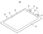
도 1은 본 발명의 일 실시예에 따른 이차전지의 사시도이다.
도 2은 도 1에 나타낸 이차전지에 적용되는 전극조립체의 탭부영역이 무탭부영역으로 권취되는 모습을 나타낸 사시도이다.
도 3은 도 2에 나타낸 전극조립체의 분해 사시도이다.
도 4는 도 3에 나타낸 전극조립체가 권취된 모습을 도시한 정면도이다.
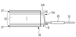
도 5는 도 2에 나타낸 전극조립체의 측단면도이다.1 is a perspective view of a secondary battery according to an embodiment of the present invention.
FIG. 2 is a perspective view illustrating a state in which a tab portion region of an electrode assembly applied to the secondary battery shown in FIG. 1 is wound into a tab-free region.
3 is an exploded perspective view of the electrode assembly shown in FIG. 2 .
4 is a front view showing a state in which the electrode assembly shown in FIG. 3 is wound.
5 is a side cross-sectional view of the electrode assembly shown in FIG.
이하, 첨부한 도면을 참고로 하여 본 발명의 여러 실시예들에 대하여 본 발명이 속하는 기술 분야에서 통상의 지식을 가진 자가 용이하게 실시할 수 있도록 상세히 설명한다. 본 발명은 여러 가지 상이한 형태로 구현될 수 있으며 여기에서 설명하는 실시예들에 한정되지 않는다.Hereinafter, with reference to the accompanying drawings, various embodiments of the present invention will be described in detail so that those of ordinary skill in the art can easily carry out the present invention. The present invention may be embodied in many different forms and is not limited to the embodiments described herein.
본 발명을 명확하게 설명하기 위해서 설명과 관계없는 부분은 생략하였으며, 명세서 전체를 통하여 동일 또는 유사한 구성요소에 대해서는 동일한 참조 부호를 붙이도록 한다.In order to clearly explain the present invention, parts irrelevant to the description are omitted, and the same reference numerals are given to the same or similar elements throughout the specification.
또한, 도면에서 나타난 각 구성의 크기 및 두께는 설명의 편의를 위해 임의로 나타내었으므로, 본 발명이 반드시 도시된 바에 한정되지 않는다.In addition, since the size and thickness of each component shown in the drawings are arbitrarily indicated for convenience of description, the present invention is not necessarily limited to the illustrated bar.
또한, 명세서 전체에서, 어떤 부분이 어떤 구성요소를 "포함" 한다고 할 때, 이는 특별히 반대되는 기재가 없는 한 다른 구성요소를 제외하는 것이 아니라 다른 구성요소를 더 포함할 수 있는 것을 의미한다. In addition, throughout the specification, when a part "includes" a certain component, this means that other components may be further included, rather than excluding other components, unless otherwise stated.
도 1은 본 발명의 일 실시예에 따른 이차전지의 사시도이다.1 is a perspective view of a secondary battery according to an embodiment of the present invention.
도 1을 참조하면, 이차전지(100)는 케이스(30) 및 케이스(30)에서 인출되는 제1 리드탭(21) 및 제2 리드탭(22)을 포함한다.Referring to FIG. 1 , the
이차전지(100)의 케이스(30)는 금속판 또는 파우치로 이루어질 수 있으며 이하에서는 파우치케이스를 예로 들어 설명한다. The
케이스(30)는 수용부(31), 테두리 접합부(33) 및 상부접합부(32)를 포함할 수 있다. 케이스(30)는 절연체를 포함하는 필름으로 이루어질 수 있다. 케이스(30)는 제1 판(미도시)과 제2 판(미도시)의 결합으로 밀폐될 수 있다. 제1 판과 제2 판은 수용부(31)의 측면에 형성되는 테두리 접합부(33)에서 열융착되어 서로 접합될 수 있다. The
수용부(31)는 케이스(30)의 제1 판 또는 제2 판 중 어느 하나에서 돌출된다. 수용부(31)에는 전극조립체(10, 도 2 참조)와 전해질이 함께 수용될 수 있다. The
제1 리드탭(21) 및 제2 리드탭(22)은 케이스(30)에서 인출되어, 이차전지(100)의 길이방향으로 돌출될 수 있다. 제1 리드탭(21) 및 제2 리드탭(22)은 케이스(30)의 상부접합부(32)에서 외부로 돌출될 수 있다. 제1 리드탭(21) 및 제2 리드탭(22)은 상부접합부(32)와 단락을 방지하기 위해 보호테이프(23)를 포함할 수 있다. The
도 2은 도 1에 나타낸 이차전지에 적용되는 전극조립체의 탭부영역 외곽으로 무탭부영역이 감싸며 권취되는 모습을 나타낸 사시도이다. FIG. 2 is a perspective view illustrating a state in which the tab-free region is wrapped around the outside of the tab region of the electrode assembly applied to the secondary battery shown in FIG. 1 .
도 2를 참고하면, 전극조립체(10)는 제1 전극(11) 및 제2 전극(12) 사이에 개재되는 세퍼레이터(13)를 포함한다. Referring to FIG. 2 , the
전극조립체(10)는 제1 전극(11) 및 제2 전극(12) 및 세퍼레이터(13)와 함께 권취되어 젤리롤과 같은 형태로 형성될 수 있다. 일 예로, 전극조립체(10)는 권취되고 프레스로 가압되어 타원형으로 제작될 수 있다. The
전극조립체(10)에는 제1 전극탭(11c) 및 제2 전극탭(12c)이 전극조립체(10)의 일측으로 돌출되어 있다. 제1 전극탭(11c) 및 제2 전극탭(12c) 각각은 제1 전극(11) 및 제2 전극(12)에서 연장된 복수개의 제1 무지탭(11b, 도 3 참조)과 제2 무지탭(12b, 도 3 참조)이 중첩되어 형성될 수 있다. In the
제1 무지탭(11b)은 제1 전극(11)에서 연장되며 전극조립체(10) 일측으로 돌출될 수 있다. 제2 무지탭(12b)은 제2 전극(12)에서 연장되며 전극조립체(10) 일측으로 돌출되고, 제1 무지탭(11b)과 이격된다. 제1 전극탭(11c) 및 제2 전극탭(12c)은 케이스(30) 내부에서 제1 리드탭(21) 및 제2 리드탭(22)과 각각 전기적으로 연결될 수 있다. The first
제1 전극(11) 및 제2 전극(12)은 제1 무지탭(11b) 및 제2 무지탭(12b)이 돌출되는 탭부영역(15a)과 탭부영역(15a)에 연결되고, 제1 무지탭(11b) 및 제2 무지탭(12b)이 돌출되지 않은 무탭부영역(17a)을 포함할 수 있다. The
탭부영역(15a)과 무탭부영역(17a)은 각각 권취되어, 전극조립체(10)의 탭부(15) 및 무탭부(17)를 이루게 되고, 무탭부(17, 도 4 참조)는 탭부(15, 도 4 참조) 외곽을 감싸게 된다. 즉, 탭부영역(15a)은 권취되면 전극조립체(10)의 길이방향으로 복수개의 제1 무지탭(11b) 및 제2 무지탭(12b)이 돌출된 탭부(15)를 형성하게 된다.The
무탭부(17)는 전극조립체(10)의 외곽에 위치하여 탭부(15) 외곽을 적어도 1회 감쌀 수 있다. 따라서, 무탭부영역(17a)은 탭부(15) 외곽을 적어도 1회 감싸는 길이(L)로 형성될 수 있다. The
무탭부(17)가 탭부(15) 외곽을 감싸면서, 탭부(15)의 제1 전극탭(11c) 및 제2 전극탭(12c)은 무탭부(17)의 두께만큼, 케이스(30)와 이격 될 수 있다. 이에 따라, 전극조립체(10)가 비정상상태에서 부풀어 오르게 될 때, 제1 전극탭(11c) 또는 제2 전극탭(12c)과 케이스(30) 사이가 단락되는 것을 방지할 수 있다. 무탭부(17)가 탭부(15)외곽을 많이 감싸게 될 경우에는 두께가 두꺼워져 단락방지의 효과가 향상되나, 집전체의 전류가 흐르는 경로의 길이를 고려하여 무탭부(17)는 탭부(15) 외곽을 3회 정도 감싸는 것이 바람직하다. While the tab-
도 3은 도 2에 나타낸 전극조립체의 분해 사시도이다. 3 is an exploded perspective view of the electrode assembly shown in FIG. 2 .
도 2 및 도 3를 참고하면, 제1 전극(11) 및 제2 전극(12)은 탭부영역(15a)과 무탭부영역(17a)을 포함할 수 있다. 2 and 3 , the
제1 전극(11)은 음극일 수 있다. 음극판은 도전성이 우수한 금속재 예를 들면, 구리 박판으로 이루어질 수 있다. 음극 코팅부는 탄소재 등의 음극 활물질에 바인더 도전재 등이 혼합된 물질로 이루어질 수 있다. 제2 전극(12)은 양극일 수 있다. 양극판은 도전성이 우수한 금속재, 예컨대 알루미늄 박판으로 이루어질 수 있다. 양극 코팅부는 리튬계 산화물에 바인더, 도전재 등이 혼합된 물질로 이루어질 수 있다. 세퍼레이터(13)는 다공성 소재로 이루어지며, 일 예로, 폴리에틸렌, 폴리프로필렌 등의 폴리올레핀으로 이루어질 수 있다.The
제1 전극(11)은, 스트립 형상의 금속 박판으로 이루어진 집전체 및 집전체의 한면 또는 양면에 활물질이 코팅되는 제1 코팅부(11a)를 포함할 수 있다. 또한, 제1 코팅부(11a) 일측에서 돌출되며 활물질이 코팅되지 않은 제1 무지탭(11b)을 포함할 수 있다. 제2 전극(12)은 제1 전극(11)과 마찬가지로 집전체의 한면 또는 양면에 활물질이 코팅되는 제2 코팅부(12a) 및 제2 코팅부(12a) 일측에서 돌출되며, 활물질이 코팅되지 않은 제2 무지탭(12b)을 포함할 수 있다. The
제1 무지탭(11b) 및 제2 무지탭(12b)은 제1 코팅부(11a) 및 제2 코팅부(12a) 일측으로 활물질이 코팅되지 않은 각각의 집전체에 무코팅 부위를 형성하고 무코팅 부위를 타발하여 형성할 수 있다. 다른 예로, 제1 무지탭(11b) 및 제2 무지탭(12b)은 집전체에 용접하여 형성될 수도 있다. The first
복수개의 제1 무지탭(11b) 및 제2 무지탭(12b)은 탭부영역(15a)에서 1회 권취될 때마다 한 개씩 제1 무지탭(11b) 및 제2 무지탭(12b)이 전극조립체(10)에 돌출될 수 있도록 이격 배치될 수 있다. 다른 예로, 1/2회 권취될 때마다 한 개씩 제1 무지탭(11b) 및 제2 무지탭(12b)이 형성되도록 탭부영역(15a)에 이격 배치될 수 있다.Each of the plurality of first
이하에서는 제1 전극을 예로 들어 탭부영역(15a)과 무탭부영역(17a)을 설명한다. Hereinafter, the
탭부영역(15a)은 제1 코팅부(11a)와 복수개의 제1 무지탭(11b)을 포함한다. 전술한 바와 같이 탭부영역(15a)이 권취되어, 전극조립체(10)에서 일측으로 복수개의 제1 무지탭(11b)이 돌출되는 탭부(15, 도 4 참조)가 된다. 무탭부영역(17a)은 탭부영역(15a)에 형성된 복수개의 제1 무지탭(11b) 중 마지막 제1 무지탭(11b)과 이격되어 탭부영역(15a)에 연결될 수 있다. 무탭부영역(17a)은 제1 코팅부(11a)를 포함할 수 있다. 다만, 무탭부영역(17a)에는 제1 무지탭(11b)이 형성되지 않는다. The
무탭부영역(17a)은 탭부영역(15a)과 일체로 형성될 수 있다. 즉, 하나의 제1 전극(11)의 집전체에 탭부영역(15a)과 무탭부영역(17a)을 형성할 수 있다. 다만, 다른 예로, 탭부영역(15a)과 무탭부영역(17a)은 따로 제작되어 탭부영역(15a)의 일측에 무탭부영역(17a)이 용접 등으로 연결될 수도 있다. The
무탭부영역(17a)의 길이(L)는, 탭부영역(15a)을 권취 했을 때 탭부(15) 외곽을 적어도 1회 감을 수 있도록 형성한다. 전술한 바와 같이 무탭부영역(17a)의 길이(L)는 탭부(15) 외곽을 1회 내지 3회를 감싸는 것이 바람직하다. 탭부영역(15a) 및 무탭부영역(17a)은 복수개로 형성되며, 서로 번갈아 배치되고 상호 연결될 수 있다. The length L of the tab-
도 4는 도 3에 나타낸 전극조립체가 권취된 모습을 도시한 정면도이다.4 is a front view showing a state in which the electrode assembly shown in FIG. 3 is wound.
도 2 내지 도 4를 참고하면, 전극조립체(10)는 탭부(15) 및 무탭부(17)를 포함한다. 2 to 4 , the
탭부(15)는 전극조립체(10) 내측에 위치하며, 제1 무지탭(11b) 및 제2 무지탭(12b)이 돌출된다. 무탭부(17)는 탭부(15) 외곽을 감싸고, 전극조립체(10)의 최외곽에 위치한다. The
무탭부(17)는 탭부(15) 외곽을 적어도 1회이상 감쌀 수 있다. 다른 예로, 무탭부(17)는 탭부(15) 외곽을 3회 감쌀 수 있다. The
탭부(15)에는 복수개의 제1 무지탭(11b) 및 제2 무지탭(12b)이 돌출된다. 제1 무지탭(11b) 및 제2 무지탭(12b)은 각각 중첩되어 제1 전극탭(11c) 및 제2 전극탭(12c)을 이룰 수 있다. 제1 전극탭(11c) 및 제2 전극탭(12c)은 제1 리드탭(21) 및 제2 리드탭(22)과 각각 연결된다. A plurality of first
무탭부(17)의 감싸는 횟수만큼, 탭부(15)는 전극조립체(10) 최외곽과 이격거리(G) 만큼 이격된다. 무탭부(17)를 3회 감싸게 되면, 이격거리(G)는 3배로 커지게 된다. 이러한 이격거리(G)로 인해 제1 무지탭(11b) 및 제2 무지탭(12b)은 케이스(30, 도 1 참조)와 단락되는 것을 방지할 수 있다. 즉, 제1 무지탭(11b) 및 제2 무지탭(12b)이 중첩되어 형성하는 제1 전극탭(11c) 및 제2 전극탭(12c)은 전극조립체(10)의 최외곽과 이격거리(G)로 이격되어, 전극조립체(10)를 수용하는 케이스(30)와 단락되는 것이 방지될 수 있다. 결국, 제1 전극탭(11c) 및 제2 전극탭(12c)은 무탭부(17) 내측으로 형성되고, 이격거리(G)는 케이스(30) 내부에서 완충공간을 형성하여 단락 방지의 효과를 향상시킬 수 있다. As much as the number of wraps of the
도 5는 도 2에 나타낸 전극조립체의 측단면도이다.5 is a side cross-sectional view of the electrode assembly shown in FIG.
도 5를 참고하면, 전극조립체(10)에서 돌출되는 복수개의 제1 무지탭(11b)은 서로 중첩되어 연결될 수 있다. Referring to FIG. 5 , the plurality of first
이하에서는, 복수개의 제1 무지탭(11b)으로 이루어진 제1 전극탭(11c)과 전기적으로 연결되는 제1 리드탭(21)을 예로 들어 설명한다. Hereinafter, the
복수개의 제1 무지탭(11b)은 전극조립체(10) 단변 방향 일측으로 가압되어 서로 겹쳐져 제1 전극탭(11c)을 형성할 수 있다. 전술한 바와 같이 무탭부(17)는 전극조립체(10)의 외곽에 위치하며 탭부(15) 외곽에 복수회 권취될 수 있으므로, 복수개의 제1 전극탭(11c) 중 최외곽에 위치하는 제1 무지탭(11b)과 전극조립체(10)의 최외곽은 이격거리(G)로 이격되어 있다. The plurality of first
무탭부(17)가 탭부(15) 외곽을 복수회 권취 할수록 이격거리(G)는 커질 수 있다. 따라서, 케이스(30, 도 1 참조)의 수용부(31, 도 1 참조)에 전극조립체(10)가 수용될 때, 케이스(30)와 전극조립체(10)의 제1 전극탭(11c) 사이에는 이격거리(G)만큼 공간이 형성될 수 있다. 따라서, 전극조립체(10)가 스웰링과 같은 현상으로 부풀어오를 때에도 제1 전극탭(11c)이 케이스(30)에 접촉되는 것을 방지할 수 있다. 즉, 제1 전극탭(11c)의 최외곽에 위치하는 제1 무지탭(11b)과 케이스(30) 사이에 형성되는 이격거리(G)는 단락 방지를 위한 완충지대와 같은 기능을 할 수 있다. As the
본 발명을 앞서 기재한 바에 따라 바람직한 실시예를 통해 설명하였지만, 본 발명은 이에 한정되지 않으며 다음에 기재하는 특허청구범위의 개념과 범위를 벗어나지 않는 한, 다양한 수정 및 변형이 가능하다는 것을 본 발명이 속하는 기술 분야에 종사하는 자들은 쉽게 이해할 것이다.Although the present invention has been described through preferred embodiments as described above, the present invention is not limited thereto, and various modifications and variations are possible without departing from the concept and scope of the following claims. Those in the technical field to which it belongs will readily understand.
100: 이차전지 10: 전극조립체
11: 제1 전극 11a: 제1 코팅부
11b: 제1 무지탭 11c: 제1 전극탭
12: 제2 전극 12a: 제2 코팅부
12b: 제2 무지탭 12c: 제2 전극탭
13: 세퍼레이터 15: 탭부
15a: 탭부영역 17: 무탭부
17a: 무탭부영역
21: 제1 리드탭 22: 제2 리드탭
30: 케이스 31: 수용부
33: 테두리 접합부 32: 상부접합부
G: 이격거리 L: 길이100: secondary battery 10: electrode assembly
11:
11b: first
12:
12b: second
13: separator 15: tab part
15a: tab part area 17: non-tap part
17a: tap-free region
21: first lead tab 22: second lead tab
30: case 31: receiving part
33: edge joint 32: upper joint
G: distance L: length
Claims (12)
상기 전극조립체를 수용하는 케이스;
를 포함하고,
상기 제1 전극은 상기 제1 탭부로부터 연장되고, 상기 제1 탭부의 최외곽을 복수 회 감싸는 제1 무탭부
상기 제2 전극은 상기 제2 탭부로부터 연장되고, 상기 제1 무탭부와 중첩하여 상기 제1 탭부의 최외곽을 복수 회 감싸는 제2 무탭부
를 더 포함하는 이차전지.A first electrode and a second active material including a first coating portion coated with a first active material and a first tab portion including a plurality of first uncoated tabs protruding from one side of the first coating portion and not coated with the first active material a second electrode including the coated second coating part and a second tab part protruding from one side of the second coating part and including a plurality of second uncoated tabs on which the second active material is not coated, the first electrode; an electrode assembly wound with a separator interposed between the second electrodes; and
a case accommodating the electrode assembly;
including,
The first electrode is a first tab-free portion extending from the first tab portion and surrounding the outermost portion of the first tab portion a plurality of times.
The second electrode extends from the second tab part, and overlaps the first tab-free part to surround the outermost part of the first tab part a plurality of times.
A secondary battery further comprising a.
상기 복수의 제1 무지탭과 전기적으로 연결되며, 케이스에서 인출되는 제1 리드탭을 더 포함하는 이차전지.The method of claim 1,
The secondary battery further comprising a first lead tab electrically connected to the plurality of first uncoated tabs and drawn out from the case.
상기 제1 무탭부는,
상기 제1 무지탭을 포함하지 않고 상기 제1 활물질이 코팅된 이차전지.The method of claim 1,
The first tapless part,
A secondary battery coated with the first active material without including the first uncoated tab.
상기 복수개의 제1 무지탭이 상기 전극조립체의 일측에서 서로 중첩되는 이차전지.3. The method of claim 2,
A secondary battery in which the plurality of first uncoated tabs overlap each other at one side of the electrode assembly.
상기 제1 탭부와 상기 제1 무탭부는 일체로 형성되는 이차전지.The method of claim 1,
A secondary battery in which the first tab portion and the first non-tab portion are integrally formed.
상기 제1 무탭부는,
상기 제1 탭부의 최외곽을 3회 감싸는 이차전지.The method of claim 1,
The first tapless part,
A secondary battery that wraps the outermost part of the first tab part three times.
상기 복수의 제2 무지탭과 전기적으로 연결되며, 케이스에서 인출되는 제2 리드탭을 더 포함하는 이차전지.The method of claim 1,
The secondary battery further comprising a second lead tab electrically connected to the plurality of second uncoated tabs and drawn out from the case.
상기 제2 무탭부는,
상기 제2 무지탭을 포함하지 않고 상기 제2 활물질이 코팅된 이차전지.The method of claim 1,
The second tapless part,
A secondary battery coated with the second active material without including the second uncoated tab.
상기 제2 전극은,
상기 복수개의 제2 무지탭이 상기 전극조립체의 일측에서 서로 중첩되는 이차전지.The method of claim 1,
The second electrode is
A secondary battery in which the plurality of second uncoated tabs overlap each other at one side of the electrode assembly.
상기 제2 탭부와 상기 제2 무탭부는 일체로 형성되는 이차전지.The method of claim 1,
A secondary battery in which the second tab portion and the second non-tab portion are integrally formed.
상기 제2 무탭부는,
상기 제2 탭부의 최외곽을 3회 감싸는 이차전지.The method of claim 1,
The second tapless part,
A secondary battery that wraps the outermost part of the second tab part three times.
Priority Applications (5)
| Application Number | Priority Date | Filing Date | Title |
|---|---|---|---|
| KR1020160092249A KR102264701B1 (en) | 2016-07-20 | 2016-07-20 | Rechargeable battery |
| US15/653,865 US10374249B2 (en) | 2016-07-20 | 2017-07-19 | Rechargeable battery |
| CN201710593907.7A CN107645010B (en) | 2016-07-20 | 2017-07-20 | rechargeable battery |
| EP17182301.6A EP3273510B1 (en) | 2016-07-20 | 2017-07-20 | Rechargeable battery |
| JP2017140743A JP6647252B2 (en) | 2016-07-20 | 2017-07-20 | Rechargeable battery |
Applications Claiming Priority (1)
| Application Number | Priority Date | Filing Date | Title |
|---|---|---|---|
| KR1020160092249A KR102264701B1 (en) | 2016-07-20 | 2016-07-20 | Rechargeable battery |
Publications (2)
| Publication Number | Publication Date |
|---|---|
| KR20180010088A KR20180010088A (en) | 2018-01-30 |
| KR102264701B1 true KR102264701B1 (en) | 2021-06-11 |
Family
ID=59383464
Family Applications (1)
| Application Number | Title | Priority Date | Filing Date |
|---|---|---|---|
| KR1020160092249A Active KR102264701B1 (en) | 2016-07-20 | 2016-07-20 | Rechargeable battery |
Country Status (5)
| Country | Link |
|---|---|
| US (1) | US10374249B2 (en) |
| EP (1) | EP3273510B1 (en) |
| JP (1) | JP6647252B2 (en) |
| KR (1) | KR102264701B1 (en) |
| CN (1) | CN107645010B (en) |
Cited By (1)
| Publication number | Priority date | Publication date | Assignee | Title |
|---|---|---|---|---|
| WO2023014018A1 (en) * | 2021-08-05 | 2023-02-09 | 주식회사 엘지에너지솔루션 | Electrode assembly, secondary battery, battery pack and automobile comprising same |
Families Citing this family (8)
| Publication number | Priority date | Publication date | Assignee | Title |
|---|---|---|---|---|
| KR102103900B1 (en) * | 2016-11-02 | 2020-04-24 | 주식회사 엘지화학 | Electrode assembly and manufacturing methode for electrode assembly |
| EP3902047B1 (en) * | 2018-12-19 | 2026-02-04 | SANYO Electric Co., Ltd. | Rectangular secondary battery |
| CN110190242A (en) | 2019-03-26 | 2019-08-30 | 宁德新能源科技有限公司 | Pole piece, battery core and battery |
| CN110518156B (en) * | 2019-10-23 | 2020-03-20 | 比亚迪股份有限公司 | Lithium ion battery, battery module, battery pack and automobile |
| HUE069784T2 (en) * | 2020-06-02 | 2025-04-28 | Contemporary Amperex Technology Hong Kong Ltd | Electrode assembly and related battery, device, manufacturing method, and manufacturing device |
| DE102021111821A1 (en) | 2021-05-06 | 2022-11-10 | Bayerische Motoren Werke Aktiengesellschaft | Electrode and electrochemical storage cell |
| JP7510404B2 (en) * | 2021-12-28 | 2024-07-03 | プライムプラネットエナジー&ソリューションズ株式会社 | battery |
| KR20250031494A (en) * | 2023-08-28 | 2025-03-07 | 삼성에스디아이 주식회사 | Rechargeable battery |
Citations (1)
| Publication number | Priority date | Publication date | Assignee | Title |
|---|---|---|---|---|
| JP2011065981A (en) * | 2009-09-18 | 2011-03-31 | Samsung Sdi Co Ltd | Manufacturing method of electrode assembly for secondary battery |
Family Cites Families (20)
| Publication number | Priority date | Publication date | Assignee | Title |
|---|---|---|---|---|
| US3028536A (en) * | 1959-09-30 | 1962-04-03 | Herbert W Bilsky | Rechargeable electric batteries |
| JPS63166143A (en) | 1986-12-27 | 1988-07-09 | Toshiba Battery Co Ltd | Sealed alkaline storage battery |
| JPH10294102A (en) | 1997-04-21 | 1998-11-04 | Honda Motor Co Ltd | Storage element |
| JP4797236B2 (en) | 2000-11-17 | 2011-10-19 | 株式会社Gsユアサ | battery |
| JP2005196974A (en) | 2003-12-26 | 2005-07-21 | Hitachi Maxell Ltd | Secondary battery |
| US7507495B2 (en) * | 2004-12-22 | 2009-03-24 | Brookhaven Science Associates, Llc | Hydrogen absorption induced metal deposition on palladium and palladium-alloy particles |
| JP2008117614A (en) | 2006-11-02 | 2008-05-22 | Sony Corp | Current collector for electrode and non-aqueous electrolyte secondary battery |
| KR100928119B1 (en) * | 2007-10-30 | 2009-11-24 | 삼성에스디아이 주식회사 | Printed Circuit Board and Secondary Battery Using the Same |
| TW200925178A (en) * | 2007-12-07 | 2009-06-16 | Univ Nat Taiwan | Polymeric polyamine and method for stabilizing silver nanoparticles using the same |
| KR101050533B1 (en) | 2008-06-18 | 2011-07-20 | 삼성에스디아이 주식회사 | Electrode assembly and secondary battery having same |
| JP2010118315A (en) | 2008-11-14 | 2010-05-27 | Toshiba Corp | Nonaqueous electrolyte battery |
| KR101156377B1 (en) | 2009-11-30 | 2012-06-13 | 삼성에스디아이 주식회사 | Secondary battery |
| KR101147237B1 (en) | 2010-07-12 | 2012-05-18 | 삼성에스디아이 주식회사 | Electrode assembly and rechargeable battery including the same |
| US8928286B2 (en) * | 2010-09-03 | 2015-01-06 | Envia Systems, Inc. | Very long cycling of lithium ion batteries with lithium rich cathode materials |
| US9159990B2 (en) * | 2011-08-19 | 2015-10-13 | Envia Systems, Inc. | High capacity lithium ion battery formation protocol and corresponding batteries |
| KR101320392B1 (en) | 2011-09-02 | 2013-10-23 | 삼성에스디아이 주식회사 | A lithium polymer battery |
| US10333113B2 (en) * | 2013-06-19 | 2019-06-25 | Samsung Sdi Co., Ltd. | Rechargeable battery having retainer |
| KR101744087B1 (en) * | 2013-06-25 | 2017-06-07 | 삼성에스디아이 주식회사 | Rechargeable battery |
| KR102161290B1 (en) | 2013-12-03 | 2020-09-29 | 삼성에스디아이 주식회사 | Flexible secondary battery |
| EP3309870B1 (en) * | 2015-06-09 | 2022-08-03 | Murata Manufacturing Co., Ltd. | Battery, battery pack, electronic instrument, electric car, power storage device and power system |
-
2016
- 2016-07-20 KR KR1020160092249A patent/KR102264701B1/en active Active
-
2017
- 2017-07-19 US US15/653,865 patent/US10374249B2/en active Active
- 2017-07-20 JP JP2017140743A patent/JP6647252B2/en active Active
- 2017-07-20 CN CN201710593907.7A patent/CN107645010B/en active Active
- 2017-07-20 EP EP17182301.6A patent/EP3273510B1/en active Active
Patent Citations (1)
| Publication number | Priority date | Publication date | Assignee | Title |
|---|---|---|---|---|
| JP2011065981A (en) * | 2009-09-18 | 2011-03-31 | Samsung Sdi Co Ltd | Manufacturing method of electrode assembly for secondary battery |
Cited By (2)
| Publication number | Priority date | Publication date | Assignee | Title |
|---|---|---|---|---|
| WO2023014018A1 (en) * | 2021-08-05 | 2023-02-09 | 주식회사 엘지에너지솔루션 | Electrode assembly, secondary battery, battery pack and automobile comprising same |
| US12451524B2 (en) | 2021-08-05 | 2025-10-21 | Lg Energy Solution, Ltd. | Electrode assembly, secondary battery, battery pack and vehicle including the same |
Also Published As
| Publication number | Publication date |
|---|---|
| JP2018014327A (en) | 2018-01-25 |
| EP3273510A1 (en) | 2018-01-24 |
| CN107645010A (en) | 2018-01-30 |
| KR20180010088A (en) | 2018-01-30 |
| JP6647252B2 (en) | 2020-02-14 |
| US10374249B2 (en) | 2019-08-06 |
| EP3273510B1 (en) | 2019-03-27 |
| CN107645010B (en) | 2020-12-08 |
| US20180026295A1 (en) | 2018-01-25 |
Similar Documents
| Publication | Publication Date | Title |
|---|---|---|
| KR102264701B1 (en) | Rechargeable battery | |
| KR101379985B1 (en) | Electrode assembly and secondary battery using the same | |
| US10693121B2 (en) | Rechargeable battery | |
| US9905881B2 (en) | Electrode assembly having protection tape and rechargeable battery including the same | |
| KR100947982B1 (en) | Electrode assembly and pouch type lithium secondary battery having same | |
| US8546005B2 (en) | Cap assembly and secondary battery having the same | |
| US9263761B2 (en) | Electrode assembly and rechargeable battery having the same | |
| US10199616B2 (en) | Battery pack including cell frames coupled to each other | |
| KR101734327B1 (en) | Pouch type secondary battery | |
| EP2560230A1 (en) | Secondary battery with improved safety | |
| US10651457B2 (en) | Battery module | |
| US8614015B2 (en) | Secondary battery and method of manufacturing secondary battery | |
| US10312497B2 (en) | Rechargeable battery | |
| KR101921730B1 (en) | Secondary Battery | |
| KR20140137603A (en) | Pouch type battery case | |
| US11189889B2 (en) | Rechargeable battery | |
| KR20130024552A (en) | Secondary battery | |
| US9698407B2 (en) | Rechargeable battery | |
| KR102809160B1 (en) | The Electrode Assembly And The Pouch Type Secondary Battery | |
| KR102504791B1 (en) | Rechargeable battery having cover | |
| US9761914B2 (en) | Battery pack | |
| KR102142661B1 (en) | Battery Cell Module | |
| US9887394B2 (en) | Rechargeable battery including fluorescent coating layer | |
| US20170117528A1 (en) | Rechargeable battery | |
| KR102337569B1 (en) | Rechargeable battery |
Legal Events
| Date | Code | Title | Description |
|---|---|---|---|
| PA0109 | Patent application |
Patent event code: PA01091R01D Comment text: Patent Application Patent event date: 20160720 |
|
| PG1501 | Laying open of application | ||
| A201 | Request for examination | ||
| PA0201 | Request for examination |
Patent event code: PA02012R01D Patent event date: 20190718 Comment text: Request for Examination of Application Patent event code: PA02011R01I Patent event date: 20160720 Comment text: Patent Application |
|
| E902 | Notification of reason for refusal | ||
| PE0902 | Notice of grounds for rejection |
Comment text: Notification of reason for refusal Patent event date: 20201006 Patent event code: PE09021S01D |
|
| E701 | Decision to grant or registration of patent right | ||
| PE0701 | Decision of registration |
Patent event code: PE07011S01D Comment text: Decision to Grant Registration Patent event date: 20210407 |
|
| GRNT | Written decision to grant | ||
| PR0701 | Registration of establishment |
Comment text: Registration of Establishment Patent event date: 20210608 Patent event code: PR07011E01D |
|
| PR1002 | Payment of registration fee |
Payment date: 20210608 End annual number: 3 Start annual number: 1 |
|
| PG1601 | Publication of registration |