KR102229937B1 - Electromagnetic heating device and smoking set having same - Google Patents
Electromagnetic heating device and smoking set having same Download PDFInfo
- Publication number
- KR102229937B1 KR102229937B1 KR1020180167082A KR20180167082A KR102229937B1 KR 102229937 B1 KR102229937 B1 KR 102229937B1 KR 1020180167082 A KR1020180167082 A KR 1020180167082A KR 20180167082 A KR20180167082 A KR 20180167082A KR 102229937 B1 KR102229937 B1 KR 102229937B1
- Authority
- KR
- South Korea
- Prior art keywords
- coil
- heating
- heating chamber
- electromagnetic induction
- induction coil
- Prior art date
- Legal status (The legal status is an assumption and is not a legal conclusion. Google has not performed a legal analysis and makes no representation as to the accuracy of the status listed.)
- Active
Links
Images


Classifications
-
- A24F47/008—
-
- A—HUMAN NECESSITIES
- A24—TOBACCO; CIGARS; CIGARETTES; SIMULATED SMOKING DEVICES; SMOKERS' REQUISITES
- A24F—SMOKERS' REQUISITES; MATCH BOXES; SIMULATED SMOKING DEVICES
- A24F40/00—Electrically operated smoking devices; Component parts thereof; Manufacture thereof; Maintenance or testing thereof; Charging means specially adapted therefor
- A24F40/40—Constructional details, e.g. connection of cartridges and battery parts
- A24F40/46—Shape or structure of electric heating means
- A24F40/465—Shape or structure of electric heating means specially adapted for induction heating
-
- A—HUMAN NECESSITIES
- A61—MEDICAL OR VETERINARY SCIENCE; HYGIENE
- A61M—DEVICES FOR INTRODUCING MEDIA INTO, OR ONTO, THE BODY; DEVICES FOR TRANSDUCING BODY MEDIA OR FOR TAKING MEDIA FROM THE BODY; DEVICES FOR PRODUCING OR ENDING SLEEP OR STUPOR
- A61M15/00—Inhalators
- A61M15/06—Inhaling appliances shaped like cigars, cigarettes or pipes
-
- H—ELECTRICITY
- H05—ELECTRIC TECHNIQUES NOT OTHERWISE PROVIDED FOR
- H05B—ELECTRIC HEATING; ELECTRIC LIGHT SOURCES NOT OTHERWISE PROVIDED FOR; CIRCUIT ARRANGEMENTS FOR ELECTRIC LIGHT SOURCES, IN GENERAL
- H05B6/00—Heating by electric, magnetic or electromagnetic fields
- H05B6/02—Induction heating
- H05B6/04—Sources of current
-
- H—ELECTRICITY
- H05—ELECTRIC TECHNIQUES NOT OTHERWISE PROVIDED FOR
- H05B—ELECTRIC HEATING; ELECTRIC LIGHT SOURCES NOT OTHERWISE PROVIDED FOR; CIRCUIT ARRANGEMENTS FOR ELECTRIC LIGHT SOURCES, IN GENERAL
- H05B6/00—Heating by electric, magnetic or electromagnetic fields
- H05B6/02—Induction heating
- H05B6/10—Induction heating apparatus, other than furnaces, for specific applications
- H05B6/105—Induction heating apparatus, other than furnaces, for specific applications using a susceptor
-
- H—ELECTRICITY
- H05—ELECTRIC TECHNIQUES NOT OTHERWISE PROVIDED FOR
- H05B—ELECTRIC HEATING; ELECTRIC LIGHT SOURCES NOT OTHERWISE PROVIDED FOR; CIRCUIT ARRANGEMENTS FOR ELECTRIC LIGHT SOURCES, IN GENERAL
- H05B6/00—Heating by electric, magnetic or electromagnetic fields
- H05B6/02—Induction heating
- H05B6/36—Coil arrangements
- H05B6/40—Establishing desired heat distribution, e.g. to heat particular parts of workpieces
-
- H—ELECTRICITY
- H05—ELECTRIC TECHNIQUES NOT OTHERWISE PROVIDED FOR
- H05B—ELECTRIC HEATING; ELECTRIC LIGHT SOURCES NOT OTHERWISE PROVIDED FOR; CIRCUIT ARRANGEMENTS FOR ELECTRIC LIGHT SOURCES, IN GENERAL
- H05B6/00—Heating by electric, magnetic or electromagnetic fields
- H05B6/02—Induction heating
- H05B6/36—Coil arrangements
- H05B6/44—Coil arrangements having more than one coil or coil segment
-
- A—HUMAN NECESSITIES
- A24—TOBACCO; CIGARS; CIGARETTES; SIMULATED SMOKING DEVICES; SMOKERS' REQUISITES
- A24F—SMOKERS' REQUISITES; MATCH BOXES; SIMULATED SMOKING DEVICES
- A24F40/00—Electrically operated smoking devices; Component parts thereof; Manufacture thereof; Maintenance or testing thereof; Charging means specially adapted therefor
- A24F40/20—Devices using solid inhalable precursors
-
- H—ELECTRICITY
- H02—GENERATION; CONVERSION OR DISTRIBUTION OF ELECTRIC POWER
- H02J—ELECTRIC POWER NETWORKS; CIRCUIT ARRANGEMENTS OR SYSTEMS FOR SUPPLYING OR DISTRIBUTING ELECTRIC POWER; SYSTEMS FOR STORING ELECTRIC ENERGY
- H02J7/00—Circuit arrangements for charging or discharging batteries or for supplying loads from batteries
- H02J7/865—Battery or charger load switching, e.g. concurrent charging and load supply
Landscapes
- Physics & Mathematics (AREA)
- Electromagnetism (AREA)
- Health & Medical Sciences (AREA)
- Engineering & Computer Science (AREA)
- Bioinformatics & Cheminformatics (AREA)
- Pulmonology (AREA)
- Anesthesiology (AREA)
- Biomedical Technology (AREA)
- Heart & Thoracic Surgery (AREA)
- Hematology (AREA)
- Life Sciences & Earth Sciences (AREA)
- Animal Behavior & Ethology (AREA)
- General Health & Medical Sciences (AREA)
- Public Health (AREA)
- Veterinary Medicine (AREA)
- General Induction Heating (AREA)
Abstract
본원 발명은 전자 흡연 도구 기술분야에 관한 것으로 가열장치 및 흡연 도구를 개시하는데 여기서 상기 가열장치는, 가열 챔버; 상기 가열 챔버의 외곽에 감김 설치됨과 동시에 적어도 상기 가열 챔버의 일단에 설치되는 제1 코일과 상기 가열 챔버의 타단에 설치되는 제2 코일을 포함하고 상기 가열 챔버 양단의 가열속도가 상이하도록 상기 제1 코일의 권수가 상기 제2 코일의 권수보다 많은 전자기 유도 코일을 포함한다. 이상의 방식을 통해 본원 발명의 실시예는 구조가 간단하고 구역을 나누어 가열할 수 있어 흡입과정에서 담배 맛이 일치하도록 유지할 수 있다.The present invention relates to the technical field of electronic smoking tools, and discloses a heating device and a smoking device, the heating device comprising: a heating chamber; The first coil includes a first coil installed at one end of the heating chamber and a second coil installed at the other end of the heating chamber while being wound around the heating chamber, and heating rates at both ends of the heating chamber are different. The number of turns of the coil includes an electromagnetic induction coil that is greater than the number of turns of the second coil. Through the above method, the embodiment of the present invention has a simple structure and can be heated by dividing the zones, so that the taste of cigarettes can be kept consistent during the inhalation process.
Description
본원 발명은 전자 흡연 도구 기술분야에 관한 것으로 특히 가열장치 및 흡연 도구에 관한 것이다.TECHNICAL FIELD The present invention relates to the field of electronic smoking tools, and in particular to heating devices and smoking tools.
우리나라의 흡연자 수는 날로 증가하고 있고 담배는 우리에게 있어서 어디서나 볼 수 있는 것이 되어 간접 흡연을 피하기란 쉬운 일이 아니다. 전통적인 궐련은 불로 점화하여 연소함으로써 연기를 발생하고 연초는 고온 연소 과정에서 인체에 해로운 많은 물질을 방출하게 된다. 대부분 흡연자는 담배를 피는 위해성을 분명히 알고 있으나 자아적으로 제어할 수 없어 금연은 아득한 일이 되어버린다.The number of smokers in Korea is increasing day by day, and cigarettes are ubiquitous for us, so avoiding secondhand smoke is not an easy task. Traditional cigarettes are ignited with fire to produce smoke, and cigarettes release many substances that are harmful to the human body during the high-temperature combustion process. Most smokers are clearly aware of the risk of smoking, but they cannot control themselves, so quitting smoking becomes a distant task.
최근 몇 년간 저온 로스팅 흡연 도구가 나타났는데 저온 로스팅을 통해 연기를 발생함으로써 유해물질의 발생을 크게 저하시킨다. 시장에 출시된 저온 로스팅 흡연 도구는 일반적으로 히터를 포함하는데 궐련을 히터에 삽입하고 히터를 통해 궐련을 가열함으로써 연기를 발생한다.In recent years, low-temperature roasting smoking tools have appeared, and by generating smoke through low-temperature roasting, the generation of harmful substances is greatly reduced. Low-temperature roasting smoking tools on the market generally include a heater, which generates smoke by inserting the cigarette into the heater and heating the cigarette through the heater.
본원 발명을 실현하는 과정에서 발명자는 관련 기술에 다음과 같은 문제점이 존재함을 발견하였다: 관련 기술의 흡연 도구의 가열장치는 담배를 일회적으로 균일하게 가열하여 그 뒤의 흡입과정에 향기와 연기의 농도를 절감시킴으로써 전후의 맛이 일치하지 않도록 하여 사용자의 체험에 영향을 준다.
본 발명의 배경이 되는 기술은 국제공개공보 WO2017/068098 (2017.04.27.) 및 대한민국 공개특허공보 제10-2012-0107914호(2012.10.04.)에 개시되어 있다.In the process of realizing the present invention, the inventors discovered that the following problems exist in the related technology: The heating device of the smoking tool of the related technology heats the cigarette uniformly once, By reducing the concentration, the taste before and after is not matched, thereby affecting the user's experience.
The technology behind the present invention is disclosed in International Publication No. WO2017/068098 (2017.04.27.) and Korean Patent Publication No. 10-2012-0107914 (2012.10.04.).
본원 발명의 실시예가 주요하게 해결하고자 하는 기술적 과제는 가열장치 및 이 가열장치를 구비하는 흡연도구를 제공함으로써 구조가 간단하고 구역을 나누어 가열할 수 있어 흡입과정에 담배 맛이 일치하게 유지하도록 한다.The main technical problem to be solved by the embodiments of the present invention is to provide a heating device and a smoking tool provided with the heating device, so that the structure is simple and can be heated by dividing the zones so that the taste of cigarettes is consistent during the inhalation process.
상기 기술적 과제를 해결하기 위하여 본원 발명의 실시예가 사용한 하나의 기술적 해결수단은 가열 챔버; 상기 가열 챔버의 외곽에 감김 설치됨과 동시에 적어도 상기 가열 챔버의 일단에 설치되는 제1 코일과 상기 가열 챔버의 타단에 설치되는 제2 코일을 포함하고 상기 가열 챔버 양단의 가열속도가 상이하도록 상기 제1 코일의 권수가 상기 제2 코일의 권수보다 많은 전자기 유도 코일을 포함하는 가열장치를 제공한다.One technical solution used by an embodiment of the present invention to solve the above technical problem is a heating chamber; The first coil includes a first coil installed at one end of the heating chamber and a second coil installed at the other end of the heating chamber while being wound around the heating chamber, and heating rates at both ends of the heating chamber are different. It provides a heating device including an electromagnetic induction coil in which the number of turns of the coil is greater than that of the second coil.
여기서 상기 전자기 유도 코일은 상기 제1 코일과 상기 제2 코일과 각각 연결되는 연결 코일을 더 포함한다.Here, the electromagnetic induction coil further includes a connection coil connected to the first coil and the second coil, respectively.
여기서 상기 제1 코일과 상기 제2 코일은 동일한 도선이 권취되어 형성된다.Here, the first coil and the second coil are formed by winding the same conductor wire.
여기서 상기 가열장치는, 상기 가열 챔버와 상기 전자기 유도 코일의 외곽에 설치되어 상기 전자기 유도 코일의 나선방향으로 연장되고 상기 전자기 유도 코일의 자력선방향을 변화시키기 위한 상자성 부재를 더 포함한다.Here, the heating device further includes a paramagnetic member installed outside the heating chamber and the electromagnetic induction coil, extending in a spiral direction of the electromagnetic induction coil, and changing a magnetic field direction of the electromagnetic induction coil.
여기서 상기 가열 챔버는 금속으로 제조된 가열통과 권선 지지대를 더 포함하되 상기 가열통은 발연물질을 수용하기 위한 것이고 상기 권선 지지대는 상기 가열통에 씌움 설치되며 상기 전자기 유도 코일은 상기 권선 지지대에 감김 설치되고 상기 상자성 부재는 상기 권선 지지대에 설치된다.Here, the heating chamber further includes a heating tube made of metal and a winding supporter, wherein the heating tube is for accommodating a fuming material, the winding support is installed over the heating tube, and the electromagnetic induction coil is wound around the winding supporter. And the paramagnetic member is installed on the winding support.
여기서 상기 가열 챔버는 권선 지지대, 금속으로 제조된 가열 플러그와 받침대를 포함하되 상기 가열 플러그는 발연물질을 삽입하기 위한 것이고 상기 가열 플러그는 상기 받침대에 설치되며 상기 권선 지지대는 상기 가열 플러그와 상기 받침대에 씌움 설치되고 상기 전자기 유도 코일은 상기 권선 지지대에 감김 설치되며 상기 상자성 부재는 상기 권선 지지대에 설치된다.Here, the heating chamber includes a winding supporter, a heating plug made of metal, and a supporter, wherein the heating plug is for inserting a fuming material, and the heating plug is installed on the supporter, and the winding supporter is attached to the heating plug and the supporter. Covering is installed and the electromagnetic induction coil is wound around the winding support, and the paramagnetic member is installed on the winding support.
여기서 상기 권선 지지대에는 요홈이 설치되고 상기 요홈은 제1 요홈과 제2 요홈을 포함하며 상기 제1 코일은 상기 제1 요홈에 일부 임베이딩되고 상기 제2 코일은 상기 제2 요홈에 일부 임베이딩된다.Here, a groove is installed in the winding support, the groove includes a first groove and a second groove, and the first coil is partially embedded in the first groove, and the second coil is partially embedded in the second groove. Ding.
여기서 상기 상자성 부재는 누름부, 제1 고정부와 제2 고정부를 포함하되 상기 제1 고정부와 제2 고정부는 상기 누름부의 양단에 각각 설치되고 상기 제1 고정부와 상기 가열 챔버의 일단은 고정되며 상기 제2 고정부와 상기 가열 챔버의 타단이 고정되고 상기 누름부와 상기 가열 챔버는 상기 전자기 유도 코일을 클램핑한다.Here, the paramagnetic member includes a pressing part, a first fixing part, and a second fixing part, wherein the first fixing part and the second fixing part are respectively installed at both ends of the pressing part, and one end of the first fixing part and the heating chamber is It is fixed and the second fixing part and the other end of the heating chamber are fixed, and the pressing part and the heating chamber clamp the electromagnetic induction coil.
여기서 상기 상자성 부재의 수량은 다수개이고 다수의 상기 상자성 부재는 상기 가열 챔버의 주변에 균일하게 분포된다.Here, the number of the paramagnetic members is plural, and the plurality of paramagnetic members are uniformly distributed around the heating chamber.
여기서 상기 상자성 부재는 중공인 동시에 일단에 개구가 설치된 소켓연결부재이고 상기 상자성 부재는 상기 가열 챔버에 씌움 설치되며 상기 상자성 부재와 상기 가열 챔버는 상기 전자기 유도 코일을 클램핑한다.Here, the paramagnetic member is a socket connection member that is hollow and has an opening at one end, and the paramagnetic member is installed to cover the heating chamber, and the paramagnetic member and the heating chamber clamp the electromagnetic induction coil.
여기서 상기 상자성 부재는 망간 페라이트, 아연 페라이트, 니켈 아연 페라이트와 망간 마그네슘 아연 페라이트에서의 한가지 또는 여러 가지 재료로 제조된다.Here, the paramagnetic member is made of one or several materials of manganese ferrite, zinc ferrite, nickel zinc ferrite, and manganese magnesium zinc ferrite.
상기 기술적 과제를 해결하기 위하여 본원 발명의 실시예에서 사용하는 다른 한 기술적 해결수단은 상기 가열장치를 포함하는 흡연 도구를 제공하는 것이다.Another technical solution used in an embodiment of the present invention to solve the above technical problem is to provide a smoking tool including the heating device.
여기서 상기 흡연 도구는, 상기 가열장치의 상기 전자기 유도 코일과 전기적으로 연결되어 상기 전자기 유도 코일에 교류전류를 제공하기 위한 전원모듈을 더 포함한다.Here, the smoking tool further includes a power module electrically connected to the electromagnetic induction coil of the heating device to provide an alternating current to the electromagnetic induction coil.
본원 발명의 실시예의 유리한 효과는 다음과 같다: 선행기술의 상황과는 달리 본원 발명의 실시예는 가열장치 및 흡연 도구를 제공하는데 여기서 이 가열장치는 가열 챔버; 상기 가열 챔버 밖에 감김 설치됨과 동시에 적어도 상기 가열 챔버의 일단에 설치되는 제1 코일과 상기 가열 챔버의 타단에 설치되는 제2 코일을 포함하고 상기 가열 챔버 양단의 가열속도가 상이하도록 상기 제1 코일의 권수가 상기 제2 코일의 권수보다 많은 전자기 유도 코일을 포함한다. 이상의 방식을 통해 본원 발명의 실시예는 구조가 간단하고 구역을 나누어 가열할 수 있어 흡입과정에서 담배 맛이 일치하도록 유지할 수 있다.Advantageous effects of the embodiments of the present invention are as follows: In contrast to the circumstances of the prior art, the embodiments of the present invention provide a heating device and a smoking tool, wherein the heating device comprises: a heating chamber; The first coil includes a first coil installed at one end of the heating chamber and a second coil installed at the other end of the heating chamber while being wound outside the heating chamber, and heating rates of both ends of the heating chamber are different. It includes an electromagnetic induction coil in which the number of turns is greater than the number of turns of the second coil. Through the above method, the embodiment of the present invention has a simple structure and can be heated by dividing the zones, so that the taste of cigarettes can be kept consistent during the inhalation process.
하나 또는 다수의 실시예는 그와 대응되는 도면에서의 이미지를 통해 예시적으로 설명되나 이러한 예시적인 설명은 실시예를 한정하기 위한 것이 아니고 도면에서 동일한 참조숫자부호를 가지는 소자는 유사한 소자를 나타내며 특별히 설명되지 않은 한 도면에서의 이미지는 비례에 대해 한정하지 않는다.
도 1은 본원 발명의 일 실시예에서 제공하는 흡연 도구의 구조모식도이다.
도 2는 도 1이 도시하는 흡연 도구의 국부적인 구조모식도이다.
도 3은 도 2가 도시하는 가열장치의 권선 지지대의 구조모식도이다.
도 4는 본원 발명의 다른 실시예에서 제공하는 가열통의 구조모식도이다.
도 5는 본원 발명의 또 다른 실시예에서 제공하는 가열 챔버의 구조 모식도이다.
도 6은 도 5에서 도시하는 가열 플러그의 구조모식도이다.
도 7은 본원 발명의 또 다른 실시예에서 제공하는 상자성 부재의 구조모식도이다.
도 8a는 본원 발명이 제공하는 상자성 부재를 추가하지 않을 경우의 전자기 유도 코일의 자기장 모식도이다.
도 8b는 도1에서 도시하고 제공하는 상자성 부재를 추가한 후 전자기 유도 코일의 자기장 모식도이다.
도 9는 본원 발명의 또 다른 실시예에서 제공하는 가열장치의 구조모식도이다.
도 10은 본원 발명의 실시예에서 제공하는 전원모듈의 구조모식도이다.One or more embodiments are exemplarily described through images in the drawings corresponding thereto, but these exemplary descriptions are not intended to limit the embodiments, and elements having the same reference numerals in the drawings represent similar elements, and in particular, Unless described, the images in the drawings are not limited to proportion.
1 is a schematic structural diagram of a smoking tool provided in an embodiment of the present invention.
FIG. 2 is a structural schematic diagram of the smoking tool shown in FIG. 1.
3 is a structural schematic diagram of the winding support of the heating device shown in FIG. 2.
Figure 4 is a schematic structural diagram of a heating tube provided in another embodiment of the present invention.
5 is a schematic structural diagram of a heating chamber provided in another embodiment of the present invention.
6 is a schematic structural diagram of the heating plug shown in FIG. 5.
7 is a structural schematic diagram of a paramagnetic member provided in another embodiment of the present invention.
8A is a schematic diagram of a magnetic field of an electromagnetic induction coil when a paramagnetic member provided by the present invention is not added.
8B is a schematic diagram of a magnetic field of an electromagnetic induction coil after adding a paramagnetic member shown and provided in FIG. 1.
9 is a schematic structural diagram of a heating device provided in another embodiment of the present invention.
10 is a schematic structural diagram of a power module provided in an embodiment of the present invention.
본원 발명을 용이하게 이해하기 위하여 이하 도면과 구체적인 실시예를 결부하여 본원 발명에 대해 더 상세히 설명하고자 한다. 설명해야 할 것은 소자가 다른 소자에 "고정"되었다고 할 경우 이는 다른 한자에 직접적으로 고정되거나 또는 그 사이에 하나 또는 다수의 소자가 존재할 수 있음을 말한다. 하나의 소자가 다른 한 소자에 "연결"되었다고 할 경우 이는 다른 한 소자에 직접적으로 연결되거나 또는 그 사이에 하나 또는 다수의 소자가 존재할 수 있음을 말한다. 본 명세서에서 사용하는 용어 "수직된", "수평된", "좌", "우", "상", "하", "내", "외", "밑부분" 등이 지시하는 방위 또는 위치 관계는 도면이 도시하는 방위 또는 위치 관계로서 본원 발명을 용이하게 설명하고 설명을 간략화하기 위한 것일 뿐 지시하는 장치 또는 소자가 반드시 특정된 방위, 특정된 방위구조와 동작을 구비함을 지시하거나 암시하기 위한 것이 아니므로 본원 발명에 대한 한정으로 이해해서는 안된다. 이 외에 용어 "제1", "제2" 등은 목적을 설명하기 위한 것일 뿐 상대적인 중요성을 지시하거나 암시하기 위한 것으로 이해되어서는 아니된다.In order to easily understand the present invention, the present invention will be described in more detail in conjunction with the accompanying drawings and specific examples. It should be explained that when an element is said to be "fixed" to another element, it means that it is directly fixed to another Chinese character, or that one or more elements may exist between them. When one element is said to be “connected” to another element, this means that it is directly connected to the other element or that one or more elements may exist between them. Orientation indicated by the terms "vertical", "horizontal", "left", "right", "top", "bottom", "inside", "outside", "bottom", and the like used herein The positional relationship is an orientation or positional relationship shown in the drawings, and is intended to easily describe and simplify the description of the present invention, and indicates or implies that the indicating device or element necessarily has a specified orientation, a specified orientation structure and operation. It is not intended to be understood as a limitation to the present invention. In addition, the terms "first", "second", and the like are only for explaining purpose and should not be understood as indicating or implying their relative importance.
별도로 정의되지 않은 한 본 명세서에서 사용하는 모든 기술적 용어와 과학적 용어는 본원 발명이 속하는 기술분야에서 통상의 지식을 가진 자들이 통상적으로 이해하는 의미와 동일하다. 본원 발명의 명세서에서 사용하는 용어는 구체적인 실시예의 목적을 설명하기 위한 것일 뿐 본원 발명을 한정하기 위한 것이 아니다. 본 명세서에서 사용하는 용어 "및/또는"은 하나 또는 다수의 관련 열거 항목의 임의의 조합과 모든 조합을 포함한다.Unless otherwise defined, all technical and scientific terms used in this specification have the same meaning as commonly understood by those of ordinary skill in the art to which the present invention belongs. The terms used in the specification of the present invention are for explaining the purpose of specific examples and not for limiting the present invention. As used herein, the term "and/or" includes any and all combinations of one or more related listed items.
이 외에 아래에서 설명하는 본원 발명의 상이한 실시예에 관한 기술적 특징은 서로 충돌되지 않는 한 서로 결합될 수 있다.In addition, technical features of different embodiments of the present invention described below may be combined with each other as long as they do not conflict with each other.
도 1을 참조하면 이는 본원 발명의 일 실시예에서 제공하는 흡연 도구의 구조모식도이다. 본원 발명의 실시예에서 제공하는 흡연 도구(200)는 가열장치(100)와 케이싱(210)을 포함하고 가열장치(100)는 케이싱(210) 내에 설치된다.Referring to Figure 1, this is a schematic structural diagram of a smoking tool provided in an embodiment of the present invention. The
구체적으로 도 2를 참조하면 상기 가열장치(100)는 전자기 유도 코일(110), 가열 챔버(120)와 상자성 부재(130)를 포함하는데 전자기 유도 코일(110)은 가열 챔버(120)의 외곽에 감김 설치되고 상자성 부재(130)는 전자기 유도 코일(110)과 가열 챔버(120)의 외곽에 설치되어 전자기 유도 코일(110)의 나선방향을 따라 축방향으로 연장된다.Specifically, referring to FIG. 2, the
상기 전자기 유도 코일(110)은 도전재료로 제조될 수 있는데 예하면 도전성능이 양호하고 가격이 저렴한 동선, 알루미늄선 등 일 수 있다. 전자기 유도 코일(110)은 통일된 방향을 따라 가열 챔버(120)의 외주에 감김 설치되어 가열 챔버에 대해 전자기 유도 가열을 진행한다. 전자기 유도법칙에 근거하면 전자기 유도 코일(120)에 교류하는 전류가 통할 경우 전자기 유도 코일(110)의 내부에는 교류 자계가 발생하게 되는데 교류 자계는 가열 챔버(120) 내에서 유도 전위를 발생함과 동시에 자기장 내의 자력선이 가열 챔버(120)를 통과할 경우 자력선은 가열 챔버(120)에 의해 절단되어 가열 챔버(120)에서 유도 전류, 즉 와류를 발생하여 가열 챔버(120)를 가열한다.The
여기서 도 2를 참조하면 전자기 유도 코일(110)은 제1 코일(111), 제2 코일(112)과 연결 코일(113)을 포함한다. 제1 코일(111)은 가열 챔버(120)의 일단에 설치되고 제2 코일(112)은 가열 챔버(120)의 타단에 설치되며 가열 챔버(120) 양단의 가열속도가 상이하도록 제1 코일(111)의 권수는 제2 코일(112)의 권수보다 많다. 연결 코일(113)은 제1 코일(111)과 제2 코일(112)에 각각 연결되고 연결 코일(113)은 가열 챔버(120)의 중단에 감김 설치된다. 본 실시예에서 동일한 조건하에 전자기 유도 코일의 권수가 많을수록 가열 챔버(120)가 절단하는 자력선이 더 많고 발생하는 유도 전류도 더 많으며 가열속도도 더 빠르다. 선택적으로 가열 챔버(120)에 담배를 넣을 경우 만약 담배가 제1 단부, 중부와 제2 단부를 포함하고 물부리에 가까운 일단을 제1 단부, 물비리와 멀리 있는 일단을 제2 단부, 중부는 제1 단부와 제2 단부 사이에 위치하며 제1 코일(111)이 제1 단부에 씌움 설치되고 제2 코일(112)이 제2 단부에 씌움 설치되어 제1 단부의 가열속도가 제2 단부보다 빠르고 중부가 제1 단부와 제2 단부의 열전달에 의해 가열한다고 가정하면 가열속도가 빠른 데로부터 늦은 데로의 순서는 제1 단부, 중부, 제2 단부이고 담배의 제1 단부의 가열이 완료되면 중부와 제2 단부가 계속하여 가열되며 중부의 가열이 완료되면 제2 단부가 계속하여 가열되어 흡입과정에서 향기와 농도가 균일하도록 할 수 있고 흡입과정에 따라 저하하는 것을 방지함으로써 사용자 체험이 더 양호하도록 한다.Here, referring to FIG. 2, the
이해할 수 있는 것은 일부 기타 실시예에서 연결 코일(113)은 생략할 수 있고 제1 코일(111)과 제2 코일(112)은 동일한 도선으로 권취하여 형성할 수 있다.It is understood that in some other embodiments, the
이해할 수 있는 것은 일부 기타 실시예에서 전자기 유도 코일(110) 외에 절연층(미도시)을 도포할 수 있는데 절연층은 전자기 유도 코일(110)이 누전되는 것을 방지한다. 절연층은 합성수지, 에폭시 수지, 페놀 수지, 4250플라스틱, 폴리이미드 플라스틱, 성형 플라스틱과 같은 절연재료로 제조된다.It is understood that in some other embodiments, an insulating layer (not shown) may be applied in addition to the
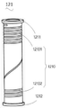
상기 가열 챔버(120)는 권선 지지대(121)와 가열통(122)을 포함한다. 권선 지지대(121)는 가열통(122)에 씌움 설치되고 전자기 유도 코일(110)은 권선 지지대(121)에 감김 설치되며 상자성 부재(130)는 권선 지지대(121)에 설치되어 전자기 유도 코일(110)의 자력선 방향을 변화하는데 사용된다.The
여기서 도 3을 함께 참조하면 권선 지지대(121)는 비금속재료로 제조되거나 또는 기타 전자기 유도를 발생하지 않는 재료로 제조된다. 권선 지지대(121)에는 요홈(1210)이 설치되고 요홈(1210)은 제1 요홈(12101)과 제2 요홈(12102)을 포함하는데 제1 코일(111)은 제1 요홈(12101)에 일부 임베이딩되며 제2 코일(112)은 제2 요홈(12102)에 일부 임베이딩되어 전자기 유도 코일(110)에 감김 설치된다. 권선 지지대(121)의 양단에는 제1 블로킹부(1211)와 제2 블로킹부(1212)가 각각 설치되고 제1 블로킹부(1211)와 제2 블로킹부(1212)의 모양은 모두 환형 일 수 있으며 제1 블로킹부(1211)와 제2 블로킹부(1212)는 모두 권선 지지대(121)를 둘러쌓아 전자기 유도 코일(110)이 더 안정적으로 권선 지지대(121)에 감김 설치되도록 한다.Here, referring to FIG. 3 together, the winding
이해할 수 있는 것은 일부 기타 실시예에서 요홈(1210)은 생략될 수 있고 전자기 유도 코일(110)은 고온에 강한 접착제를 도포하는 등 기타 방식으로 권선 지지대(121)에 고정될 수 있다.It will be appreciated that in some other embodiments the
상기 가열통(122)은 중공 원기둥체로서 금속도체로 제조되는데 바람직하게는 철분말 코어, 철 니켈 50, 철 실리콘 알루미늄, 철 니켈 몰리브덴 등과 같은 투자성 재료로 제조되어 유도 가열의 효과가 더 양호하도록 한다. 가열통(122)의 표면은 매끄러워 전자기 유도 가열의 효과가 더 양호하도록 한다. 가열통(122)에는 발연물질을 수용하기 위한 수용챔버(미도시)가 설치된다. 여기서 발연물질은 예하면 살담배, 연초시트, 연초분말에서의 한가지 또는 여러 가지로 성형된 연초봉이나 시트일 수 있다.The
이해할 수 있는 것은 일부 기타 실시예에서는 도 4에 도시된 바와 같이 가열통(122)은 제1 통부(1221)와 제2 통부(1222)를 포함하고 제1 통부(1221)는 제2 통부(1222)와 연결되며 수용챔버는 제1 통부(1221)와 제2 통부(1222)에 연통되고 제1 통부(1221)의 중심축선과 제2 통부(1222)의 중심축선은 동축일 수 있다. 제1 통부(1221)의 내경과 제2 통부(1222)의 내경은 동일하고 제1 통부(1221)의 외경은 제2 통부(1222)의 외경보다 작아 제2 통부(1222)의 질량이 제1 통부(1221)의 질량보다 크도록 한다. 제1 코일(111)이 감김 설치되는 위치와 제1 통부(1221)가 대응되고 제2 코일(112)이 감김 설치되는 위치와 제2 통부(1222)가 대응되면 동일한 조건에서 동일한 온도까지 상승할 경우 질량이 큰 것이 수요하는 시간이 더 많으므로 제1 통부(1221)의 가열속도가 제2 통부(1222)의 가열속도보다 더 빠르도록 한다.It is understood that in some other embodiments, as shown in FIG. 4, the
이해할 수 있는 것은 일부 기타 실시예에서는 도 5와 도 6에 도시된 바와 같이 가열통(122)을 생략할 수 있고 상기 가열 챔버(120)는 권선 지지대(121), 가열 플러그(123)와 받침대(124)를 포함한다. 가열 플러그(123)는 발연물질을 삽입하기 위한 것이고 가열 플러그(123)는 받침대(124)에 설치된다. 권선 지지대(121)는 가열 플러그(123)와 받침대(124)에 씌움 설치되고 전자기 유도 코일(110)은 권선 지지대(121)에 감김 설치되며 상자성 부재(130)는 권선 지지대(121)에 설치된다. 여기서 권선 지지대(121)는 상기 실시예와 동일하므로 여기서 더이상 설명하지 않는다. 가열 플러그(123)는 대체적으로 판형상이고 금속재료로 제조되어 순금속, 합금, 금속화합물 또는 특수금속재료 일 수 있으며 예하면 철, 동, 알루미늄, 주석, 니켈, 금, 은, 납, 아연 및 이의 합금 등 일 수 있다. 가열 플러그(123)에는 핀(1231)이 설치되고 핀(1231)의 모양은 삼각기둥으로 되어 가열 플러그(123)로 하여금 고체 발연물질에 더 용이하게 삽입되고 가열의 접촉면적을 증가하도록 한다. 받침대(124)는 권선 지지대(121)에 고정되어 가열 플러그(123)를 지지함으로써 가열 플러그(123)로 하여금 권선 지지대(121) 내에 수직되게 설치되도록 한다. 가열 플러그(123)와 받침대(124)를 설치함으로써 가열장치(100)로 하여금 중심 가열을 실현하도록 하여 여러 가지 가열방식의 수요를 만족시키도록 한다.It can be understood that in some other embodiments, the
상기 상자성 부재(130)는 망간 페라이트, 아연 페라이트, 니켈 아연 페라이트와 망간 마그네슘 아연 페라이트에서의 한가지 또는 여러 가지 재료로 제조된다. 상자성 부재(130)의 모양은 통형상이고 중공인 동시에 일단에 개구가 설치된 소켓연결부재이며 상자성 부재(130)는 가열 챔버(120)에 씌움 설치되고 가열 챔버(120)는 전자기 유도 코일(110)을 클램핑할 수 있다.The
이해할 수 있는 것은 일부 기타 실시예에서 도 7에 도시된 바와 같이 상기 상자성 부재(130)는 누름부(131), 제1 고정부(132)와 제2 고정부(133)를 포함하고 제1 고정부(132)와 제2 고정부(133)는 누름부(131)의 양단에 고정되며 제1 고정부(132)는 가열 챔버(120)의 일단에 고정되고 제2 고정부(133)는 가열 챔버(120)의 타단에 고정되며 누름부(131)와 가열 챔버(120)는 전자기 유도 코일(110)을 클램핑한다. 여기서 제1 고정부(132)는 권선 지지대(121)의 제1 블로킹부(1211)와 고정되고 제2 고정부(133)는 권선 지지대(121)의 제2 블로킹부(1212)와 고정될 수 있다. 상자성 부재(130)의 수량은 다수개 일 수 있고 다수의 상자성 부재(130)는 가열 챔버(120)의 주변에 균일하게 분포된다. 선택적으로 상자성 부재(130)의 수량은 4개 일 수 있는데 4개의 상자성 부재(130)는 가열 챔버(120)의 주변을 균일하게 둘러싼다. 상기 실시예와 비교하면 이러한 설치는 전자기 유도 가열 효율을 향상시킬 뿐만 아니라 재료를 감소할 수도 있다.It can be understood that in some other embodiments, as shown in FIG. 7, the
본 실시예에서는 도 8a에 도시된 바와 같이 상자성 부재(130)가 존재하지 않을 경우 전자기 유도 코일(110)에 교류하는 전류가 통하고 자기장을 발생하며 자기장의 일부 자력선은 가열 챔버(120)를 통과하고 가열 챔버(120)에 의해 절단됨으로써 가열 챔버(120)에서 유도 전류를 발생하여 가열 챔버(120)를 가열하며; 자기장의 다른 일부 자력선은 가열 챔버(120)에 의해 절단되므로 전자기 유도 코일(110)이 발생한 자기장이 유도 전류를 발생하는데 전부 사용되지 않아 대량의 에너지를 낭비하며; 도 8b에 도시된 바와 같이 상자성 부재(130)가 가열 챔버(120) 외에 씌움 설치될 경우 전자기 유도 코일(110)에 교류하는 전류가 통하고 자기장을 발생하며 자기장의 일부 자력선은 가열 챔버(120)를 통과하고 자기장의 다른 일부 자력선은 가열 챔버(120)를 통과하지 않았으나 상자성 부재(130)의 작용을 받아 자력선의 방향을 변화시켜 이 또한 가열 챔버(120)를 통과하도록 함으로써 가열 챔버(120)가 발생하는 유도 전류가 많아져 전자기 유도 가열 효율을 향상시킨다.In this embodiment, as shown in FIG. 8A, when the
본 실시예의 가열장치(100)는 전자기 유도 코일(110)과 가열 챔버(120)를 포함하고 가열 챔버(120) 양단의 전자기 유도 코일(110)에 설치한 권수가 상이함에 의해 가열 챔버(120) 양단의 가열속도가 상이함으로써 본 실시예에서의 가열장치(100)로 하여금 구조가 간단하고 구역을 나누어 가열할 수 있어 흡입과정에서 담배 맛이 일치하도록 유지할 수 있도록 하며 상자성 부재(130)가 가열 챔버(120)에 씌움 설치되어 전자기 유도 코일(110)의 자력선 방향을 변화시켜 전자기 유도 가열 효율을 향상시킬 수 있다.The
이해할 수 있는 것은 일부 기타 실시예에서 도 9에 도시된 바와 같이 상자성 부재(130)는 생략될 수 있다. 가열장치(100)는 전자기 유도 코일(110)과 가열 챔버(120)를 포함한다. 여기서 전자기 유도 코일(110), 가열 챔버(120)는 상기 실시예에서의 전자기 유도 코일(110), 가열 챔버(120)와 동일하다. 이상의 방식을 통해 가열 챔버(120) 양단의 전자기 유도 코일(110) 설치 권수가 상이하도록 하여 가열 챔버(120) 양단의 가열속도가 상이하도록 함으로써 가열장치(100)는 구역을 나누어 가열할 수 있어 흡입과정에서 담배 맛이 일치하도록 유지할 수 있다.It will be appreciated that the
상기 케이싱(210)은 플라스틱 케이싱 일 수 있는데 예하면 폴리카보네이트, 폴리우레탄, 폴리이미드 등 단열 보온효과가 우수한 플라스틱 케이싱 일 수 있다. 케이싱(210)은 가열장치(100)를 수용하는데 사용된다.The
일부 기타 실시예에서 케이싱(210)은 금속 케이싱일 수도 있는데 케이싱(210)에 플라스틱막을 도금하여 단열보온효과에 도달할 수 있다.In some other embodiments, the
여기서 상기 흡연 도구(200)는 전원모듈(220)을 더 포함하고 전원모듈(220)은 전자기 유도 코일(110)과 연결되어 전자기 유도 코일(110)에 교류전류를 제공함으로써 유도가열을 진행한다. 선택적으로 도 10에 도시된 바와 같이 전원모듈(220)은 USB포트(221), 전지(222), 제어 스위치(223), 충전회로(224) 및 방전회로(225)를 포함하는데 전지(222)는 제어 스위치(223)를 통해 방전회로(225)의 입력단과 전기적으로 연결되고 방전회로(225)의 출력단은 전자기 유도 코일(110)과 전기적으로 연결되며 전지(222)는 충전회로(224)를 통해 USB포트(221)와 전기적으로 연결된다. 구체적으로 전지(222)는 충전지이고 제어 스위치(223)는 케이싱(210)의 표면에 설치되는데 아래에는 네가지 상황으로 나누어 본 제품에 대해 설명한다. 첫번째 상황: 사용자가 제어 스위치(223)를 닫을 경우 전지(222)와 방전회로(225)의 입력단이 전기적으로 연통되고 방전회로(225)는 방전하는 작동상태에 진입함과 동시에 이의 출력단을 통해 전자기 유도 코일(110)에 전기를 공급함으로써 전자기 유도 코일(110)로 하여금 여기 자기장을 발생하도록 하여 가열 챔버(120)의 가열통(122) 또는 가열 플러그(123)가 자아 발열하도록 하여 발연물질을 가열하며 사용자는 제어 스위치(223)를 닫은 후 흡연 도구(200)를 빨아들일 수 있게 된다. 두번째 상황: 사용자가 제어 스위치(223)를 오프할 경우 전지(222)는 방전회로(225)의 입력단과 연통되지 않고 방전회로(225)는 작동하지 않는 상태에 놓이게 되며 사용자는 흡연 도구(200)를 흡입하여 연기를 발생할 수 없게 된다. 세번째 상황: USB포트(221)에 외부전원이 접속될 경우 충전회로(224)는 이 외부전원의 존재를 검출하여 충전 작동상태에 진입함으로써 충전지를 충전하게 된다. 네번째 상황: USB포트(221)에 외부전원이 접속되지 않을 경우 충전회로(224)는 외부전원의 존재를 검출할 수 없으므로 충전회로(224)는 작동하지 않는 상태에 놓이게 된다. 선택적으로 전지(222)는 리튬 충전지를 포함한다.Here, the
본 실시예의 흡연 도구(200)는 전자기 유도 가열 효율을 향상시킬 수 있는 가열장치(100)를 포함함으로써 구역을 나누어 가열할 수 있어 흡입과정에서 담배 맛이 일치하도록 유지할 수 있으며 사용자의 체험을 효과적으로 향상시키고 가열 효율을 효과적으로 향상시키며 에너지의 이용률을 향상시키고 구조가 간단하며 가격이 저렴하다.The
마지막으로 설명해야 할 것은, 이상의 실시예는 단지 본원 발명의 기술적 해결수단을 설명하기 위한 것일 뿐 이에 대해 한정하기 위한 것이 아니고 본원 발명의 맥락하에 이상의 실시예 또는 상이한 실시예의 기술적 특징 사이는 서로 조합될 수 있으며 단계는 임의의 순서로 실현될 수 있고 상술한 본원 발명의 상이한 양태의 여러 가지 기타 변화가 존재할 수 있으며 간결함을 위하여 이들은 세부 절차에서 제공되지 않았는바, 비록 상술한 실시예를 참조하여 본원 발명을 상세히 설명하였으나 본 발명이 속하는 기술분야에서 통상의 지식을 가진 자들은 응당 본원 발명이 여전히 상술한 각 실시예에 기재된 기술적 해결수단에 대해 수정할 수 있거나 그 중의 일부 기술적 특징을 동등하게 대체할 수 있으며 이러한 수정 또는 대체는 상응한 기술적 해결수단의 본질이 본원 발명의 각 실시예의 기수적 해결수단의 범위를 벗어나지 않는다는 것을 이해할 수 있다.Lastly, it should be described that the above embodiments are only for describing the technical solutions of the present invention, not for limiting them, and the technical features of the above embodiments or different embodiments may be combined with each other under the context of the present invention. And the steps may be implemented in any order, and there may be various other variations of the different aspects of the present invention described above, and for brevity these are not provided in the detailed procedures, although the present invention with reference to the above-described embodiments Although it has been described in detail, those of ordinary skill in the art to which the present invention pertains may modify the technical solutions described in each of the above-described embodiments or equivalently replace some of the technical features of the present invention. It can be understood that such modifications or substitutions do not depart from the scope of the radix solution of each embodiment of the present invention in the essence of the corresponding technical solution.
Claims (13)
상기 가열 챔버는 제1 단부, 중부 및 제2 단부를 포함하고;
상기 전자기 유도 코일은 상기 가열 챔버의 외곽에 감김 설치됨과 동시에 제1 코일, 연결 코일과 제2 코일을 포함하되, 상기 제1 코일이 상기 연결 코일을 통해 상기 제2 코일과 연결되고,
상기 제1 코일은 상기 제1 단부에 설치되고, 상기 연결 코일은 상기 중부에 설치되고, 상기 제2 코일은 상기 제2 단부에 설치되고, 상기 가열 챔버의 제1 단부 및 제2 단부에서의 가열속도가 상이하도록 상기 제1 코일의 권수가 상기 제2 코일의 권수보다 많은,
가열장치.Including a heating chamber and an electromagnetic induction coil,
The heating chamber includes a first end, a middle end and a second end;
The electromagnetic induction coil includes a first coil, a connection coil, and a second coil while being wound around the heating chamber, wherein the first coil is connected to the second coil through the connection coil,
The first coil is installed at the first end, the connecting coil is installed at the middle, and the second coil is installed at the second end, and heating at the first end and the second end of the heating chamber The number of turns of the first coil is greater than the number of turns of the second coil so that the speed is different,
Heating device.
상기 제1 코일과 상기 제2 코일은 동일한 도선이 권취되어 형성되는, 가열장치.The method of claim 1,
The first coil and the second coil are formed by winding the same conductor.
상기 가열장치는,
상기 가열 챔버와 상기 전자기 유도 코일의 외곽에 설치되어 상기 전자기 유도 코일의 나선방향으로 연장되며 상기 전자기 유도 코일의 자력선방향을 변화시키기 위한 상자성 부재를 더 포함하는, 가열장치.The method of claim 1,
The heating device,
The heating apparatus further comprises a paramagnetic member installed outside the heating chamber and the electromagnetic induction coil, extending in a spiral direction of the electromagnetic induction coil, and changing a magnetic field direction of the electromagnetic induction coil.
상기 가열 챔버는 금속으로 제조된 가열통과 권선 지지대를 더 포함하되 상기 가열통은 발연물질을 수용하기 위한 것이고 상기 권선 지지대는 상기 가열통에 씌움 설치되며 상기 전자기 유도 코일은 상기 권선 지지대에 감김 설치되고 상기 상자성 부재는 상기 권선 지지대에 설치되는, 가열장치.The method of claim 3,
The heating chamber further includes a heating tube made of metal and a winding supporter, wherein the heating tube is for accommodating a fuming material, the winding support is installed overlying the heating tube, and the electromagnetic induction coil is wound around the winding supporter. The paramagnetic member is installed on the winding support, heating device.
상기 가열 챔버는 권선 지지대, 금속으로 제조된 가열 플러그와 받침대를 포함하되 상기 가열 플러그는 발연물질을 삽입하기 위한 것이고 상기 가열 플러그는 상기 받침대에 설치되며 상기 권선 지지대는 상기 가열 플러그와 상기 받침대에 씌움 설치되고 상기 전자기 유도 코일은 상기 권선 지지대에 감김 설치되며 상기 상자성 부재는 상기 권선 지지대에 설치되는, 가열장치.The method of claim 3,
The heating chamber includes a winding supporter, a heating plug made of metal, and a supporter, wherein the heating plug is for inserting a fuming material, the heating plug is installed on the supporter, and the winding supporter covers the heating plug and the supporter. And the electromagnetic induction coil is wound around the winding support, and the paramagnetic member is installed on the winding support.
상기 권선 지지대에는 요홈이 설치되고 상기 요홈은 제1 요홈과 제2 요홈을 포함하며 상기 제1 코일은 상기 제1 요홈에 일부 임베이딩되고 상기 제2 코일은 상기 제2 요홈에 일부 임베이딩되는, 가열장치.The method according to claim 4 or 5,
A groove is installed in the winding support, the groove includes a first groove and a second groove, and the first coil is partially embedded in the first groove, and the second coil is partially embedded in the second groove. It is a heating device.
상기 상자성 부재는 누름부, 제1 고정부와 제2 고정부를 포함하되 상기 제1 고정부와 제2 고정부는 상기 누름부의 양단에 각각 설치되고 상기 제1 고정부와 상기 가열 챔버의 일단은 고정되며 상기 제2 고정부와 상기 가열 챔버의 타단이 고정되고 상기 누름부와 상기 가열 챔버는 상기 전자기 유도 코일을 클램핑하는, 가열장치.The method according to claim 4 or 5,
The paramagnetic member includes a pressing part, a first fixing part, and a second fixing part, wherein the first fixing part and the second fixing part are respectively installed at both ends of the pressing part, and the first fixing part and one end of the heating chamber are fixed. And the second fixing part and the other end of the heating chamber are fixed, and the pressing part and the heating chamber clamp the electromagnetic induction coil.
상기 상자성 부재의 수량은 다수 개이고 다수의 상기 상자성 부재는 상기 가열 챔버의 주변에 균일하게 분포되는, 가열장치.The method of claim 7,
The number of the paramagnetic members is plural and the plurality of paramagnetic members are uniformly distributed around the heating chamber.
상기 상자성 부재는 중공인 동시에 일단에 개구가 설치된 소켓연결부재이고 상기 상자성 부재는 상기 가열 챔버에 씌움 설치되며 상기 상자성 부재와 상기 가열 챔버는 상기 전자기 유도 코일을 클램핑하는, 가열장치.The method according to claim 4 or 5,
The paramagnetic member is a socket connection member that is hollow and has an opening at one end, and the paramagnetic member is installed to cover the heating chamber, and the paramagnetic member and the heating chamber clamp the electromagnetic induction coil.
상기 상자성 부재는 망간 페라이트, 아연 페라이트, 니켈 아연 페라이트와 망간 마그네슘 아연 페라이트에서의 한가지 또는 여러 가지 재료로 제조되는, 가열장치.The method according to any one of claims 3 to 5,
The paramagnetic member is made of one or more materials from manganese ferrite, zinc ferrite, nickel zinc ferrite and manganese magnesium zinc ferrite.
Applications Claiming Priority (4)
| Application Number | Priority Date | Filing Date | Title |
|---|---|---|---|
| CN201721838946.0 | 2017-12-22 | ||
| CN201721823986.8U CN207754554U (en) | 2017-12-22 | 2017-12-22 | A kind of heating device and smoking set |
| CN201721823986.8 | 2017-12-22 | ||
| CN201721838946.0U CN207754555U (en) | 2017-12-22 | 2017-12-22 | A kind of heating device and smoking set |
Publications (2)
| Publication Number | Publication Date |
|---|---|
| KR20190076892A KR20190076892A (en) | 2019-07-02 |
| KR102229937B1 true KR102229937B1 (en) | 2021-03-18 |
Family
ID=64900797
Family Applications (1)
| Application Number | Title | Priority Date | Filing Date |
|---|---|---|---|
| KR1020180167082A Active KR102229937B1 (en) | 2017-12-22 | 2018-12-21 | Electromagnetic heating device and smoking set having same |
Country Status (4)
| Country | Link |
|---|---|
| US (1) | US20190191767A1 (en) |
| EP (1) | EP3506721A1 (en) |
| JP (1) | JP6766128B2 (en) |
| KR (1) | KR102229937B1 (en) |
Cited By (1)
| Publication number | Priority date | Publication date | Assignee | Title |
|---|---|---|---|---|
| WO2024033409A1 (en) * | 2022-08-11 | 2024-02-15 | Philip Morris Products S.A. | Induction heating module for use in an inductively heating aerosol-generating device |
Families Citing this family (37)
| Publication number | Priority date | Publication date | Assignee | Title |
|---|---|---|---|---|
| KR102886364B1 (en) | 2017-12-28 | 2025-11-13 | 제이티 인터내셔널 소시에떼 아노님 | Induction heating assembly for a vapour generating device |
| CN112004433B (en) | 2018-05-17 | 2024-10-01 | 菲利普莫里斯生产公司 | Aerosol generating device with improved inductor coil |
| EP3937694A1 (en) * | 2019-03-11 | 2022-01-19 | Nicoventures Trading Limited | Aerosol provision device |
| KR102593473B1 (en) | 2019-03-11 | 2023-10-23 | 니코벤처스 트레이딩 리미티드 | Aerosol delivery device |
| GB201903251D0 (en) * | 2019-03-11 | 2019-04-24 | Nicoventures Trading Ltd | Aerosol provision device |
| WO2020182737A1 (en) * | 2019-03-11 | 2020-09-17 | Nicoventures Trading Limited | Aerosol provision device |
| KR20220027200A (en) * | 2019-07-04 | 2022-03-07 | 필립모리스 프로덕츠 에스.에이. | Induction heating arrangement with segmented induction heating elements |
| CA208741S (en) | 2019-08-01 | 2022-04-07 | Nicoventures Trading Ltd | Aerosol generating device |
| US20220287376A1 (en) * | 2019-08-23 | 2022-09-15 | Philip Morris Products S.A. | Temperature detection in peripherally heated aerosol-generating device |
| KR102317840B1 (en) * | 2019-10-11 | 2021-10-26 | 주식회사 케이티앤지 | Aerosol generating article, device and system |
| CN212117064U (en) * | 2019-12-09 | 2020-12-11 | 深圳市合元科技有限公司 | Heat insulation mechanism for gas mist generating device and gas mist generating device |
| KR102408932B1 (en) * | 2020-02-14 | 2022-06-14 | 주식회사 케이티앤지 | Aerosol generating device and aerosol generating system |
| CN212233104U (en) * | 2020-03-26 | 2020-12-29 | 深圳麦克韦尔科技有限公司 | Aerosol generating device and electromagnetic heating component thereof |
| KR102427858B1 (en) | 2020-04-22 | 2022-08-01 | 주식회사 케이티앤지 | Aerosol generating device |
| KR102509092B1 (en) | 2020-05-20 | 2023-03-10 | 주식회사 케이티앤지 | Heater assembly and manufacturing method thereof |
| EP4171282A1 (en) * | 2020-06-26 | 2023-05-03 | Nicoventures Trading Limited | Apparatus for heating aerosolisable material |
| CN111567881A (en) * | 2020-07-01 | 2020-08-25 | 深圳市康柏特科技开发有限公司 | Mobile heating assembly, aerosol generating device and implementation method |
| CN111616420A (en) * | 2020-07-17 | 2020-09-04 | 惠州市沛格斯科技有限公司 | Heating modules and smoking equipment |
| KR102579419B1 (en) * | 2020-09-16 | 2023-09-15 | 주식회사 케이티앤지 | Aerosol generating device and aerosol generating system |
| KR102508888B1 (en) * | 2020-10-21 | 2023-03-10 | 주식회사 아이티엠반도체 | Double heating type heat-emitting apparatus for electronic cigarette, heat-emitting method and electronic cigarette |
| CN114652020B (en) * | 2020-12-24 | 2024-06-21 | 东莞市亿海电子有限公司 | Electromagnetic induction electronic cigarette |
| USD985187S1 (en) | 2021-01-08 | 2023-05-02 | Nicoventures Trading Limited | Aerosol generator |
| TW202235018A (en) * | 2021-02-02 | 2022-09-16 | 瑞士商傑太日煙國際股份有限公司 | An induction heating assembly for an aerosol generating device |
| KR102630397B1 (en) * | 2021-04-16 | 2024-01-29 | 주식회사 케이티앤지 | Aerosol-generating apparatus with differential heating function and aerosol-generating article applied to the same |
| CN215455423U (en) * | 2021-06-03 | 2022-01-11 | 深圳麦克韦尔科技有限公司 | Heating member and heating atomization device |
| USD984730S1 (en) | 2021-07-08 | 2023-04-25 | Nicoventures Trading Limited | Aerosol generator |
| CN113331487A (en) * | 2021-07-19 | 2021-09-03 | 云南中烟工业有限责任公司 | Cigarette with ferromagnetic heating cap, electric heating suction system and use method |
| CN113693294A (en) * | 2021-08-30 | 2021-11-26 | 惠州市新泓威科技有限公司 | Aerosol generating device with induction heating tube |
| EP4378334A4 (en) * | 2021-09-17 | 2025-06-18 | Japan Tobacco Inc. | Aerosol generating system and method for manufacturing aerosol generating system |
| GB202117352D0 (en) * | 2021-12-01 | 2022-01-12 | Nicoventures Holdings Ltd | Aerosol generating device |
| KR102766046B1 (en) * | 2021-12-03 | 2025-02-13 | 주식회사 케이티앤지 | Heating structure and aerosol generating device and system comprising the same |
| KR102622606B1 (en) * | 2021-12-22 | 2024-01-09 | 주식회사 이노아이티 | Coil winding structure of the aerosol generating apparatus |
| CN217592037U (en) * | 2022-02-24 | 2022-10-18 | 比亚迪精密制造有限公司 | Electromagnetic induction piece, heating device and electron cigarette |
| CN114642276B (en) * | 2022-04-28 | 2026-03-20 | 惠州市沛格斯科技有限公司 | e-cigarettes |
| CN114931679A (en) * | 2022-06-30 | 2022-08-23 | 深圳麦克韦尔科技有限公司 | Heating mechanism and electronic atomization device |
| KR102886181B1 (en) * | 2022-11-14 | 2025-11-14 | 주식회사 이노아이티 | Aerosol generator |
| KR102807216B1 (en) * | 2023-04-24 | 2025-05-16 | 주식회사 이노아이티 | Aerosol generator |
Citations (4)
| Publication number | Priority date | Publication date | Assignee | Title |
|---|---|---|---|---|
| WO2017001820A1 (en) | 2015-06-29 | 2017-01-05 | Nicoventures Holdings Limited | Electronic vapour provision system |
| WO2017068098A1 (en) * | 2015-10-22 | 2017-04-27 | Philip Morris Products S.A. | Inductive heating device for heating an aerosol-forming substrate comprising a susceptor |
| US20170224015A1 (en) | 2016-02-08 | 2017-08-10 | Robert BASIL | Induction heating system |
| JP2017525348A (en) | 2014-07-24 | 2017-09-07 | アルトリア クライアント サービシーズ リミテッド ライアビリティ カンパニー | Electronic cigarette device and its parts |
Family Cites Families (10)
| Publication number | Priority date | Publication date | Assignee | Title |
|---|---|---|---|---|
| US5591368A (en) * | 1991-03-11 | 1997-01-07 | Philip Morris Incorporated | Heater for use in an electrical smoking system |
| JP3385955B2 (en) * | 1998-02-23 | 2003-03-10 | 松下電器産業株式会社 | Heating equipment |
| US7070743B2 (en) * | 2002-03-14 | 2006-07-04 | Invista North America S.A R.L. | Induction-heated reactors for gas phase catalyzed reactions |
| US6803550B2 (en) * | 2003-01-30 | 2004-10-12 | Philip Morris Usa Inc. | Inductive cleaning system for removing condensates from electronic smoking systems |
| JP2006147432A (en) * | 2004-11-22 | 2006-06-08 | Akihiko Konno | Fluid heating device and heating system |
| CN102227951A (en) * | 2009-01-07 | 2011-10-26 | 大金工业株式会社 | Electromagnetic induction heating unit and air conditioning device |
| CN201445686U (en) * | 2009-06-19 | 2010-05-05 | 李文博 | High-frequency induction atomizing device |
| CN110573035B (en) * | 2017-05-10 | 2023-06-09 | 菲利普莫里斯生产公司 | Aerosol-generating articles, devices and systems for use with multiple aerosol-forming substrates |
| AU2018334042B2 (en) * | 2017-09-15 | 2022-01-06 | Nicoventures Trading Limited | Apparatus for heating smokable material |
| GB201716735D0 (en) * | 2017-10-12 | 2017-11-29 | British American Tobacco Investments Ltd | Aerosol provision systems |
-
2018
- 2018-12-20 JP JP2018238346A patent/JP6766128B2/en active Active
- 2018-12-21 KR KR1020180167082A patent/KR102229937B1/en active Active
- 2018-12-21 US US16/229,367 patent/US20190191767A1/en not_active Abandoned
- 2018-12-22 EP EP18215813.9A patent/EP3506721A1/en active Pending
Patent Citations (4)
| Publication number | Priority date | Publication date | Assignee | Title |
|---|---|---|---|---|
| JP2017525348A (en) | 2014-07-24 | 2017-09-07 | アルトリア クライアント サービシーズ リミテッド ライアビリティ カンパニー | Electronic cigarette device and its parts |
| WO2017001820A1 (en) | 2015-06-29 | 2017-01-05 | Nicoventures Holdings Limited | Electronic vapour provision system |
| WO2017068098A1 (en) * | 2015-10-22 | 2017-04-27 | Philip Morris Products S.A. | Inductive heating device for heating an aerosol-forming substrate comprising a susceptor |
| US20170224015A1 (en) | 2016-02-08 | 2017-08-10 | Robert BASIL | Induction heating system |
Cited By (1)
| Publication number | Priority date | Publication date | Assignee | Title |
|---|---|---|---|---|
| WO2024033409A1 (en) * | 2022-08-11 | 2024-02-15 | Philip Morris Products S.A. | Induction heating module for use in an inductively heating aerosol-generating device |
Also Published As
| Publication number | Publication date |
|---|---|
| JP2019129820A (en) | 2019-08-08 |
| KR20190076892A (en) | 2019-07-02 |
| EP3506721A1 (en) | 2019-07-03 |
| US20190191767A1 (en) | 2019-06-27 |
| JP6766128B2 (en) | 2020-10-07 |
Similar Documents
| Publication | Publication Date | Title |
|---|---|---|
| KR102229937B1 (en) | Electromagnetic heating device and smoking set having same | |
| CN207754554U (en) | A kind of heating device and smoking set | |
| JP6767455B2 (en) | Heating device and low temperature heating type smoking equipment | |
| CN207754555U (en) | A kind of heating device and smoking set | |
| EP2724630B1 (en) | Atomizing device and electronic cigarette having same | |
| JP6766192B2 (en) | Heating device and electronic cigarette | |
| EP3939380B1 (en) | Aerosol provision device | |
| US5686006A (en) | Induction cooker with coil support having spiral-shaped housing for spiral coil | |
| US12127595B2 (en) | Aerosol provision device | |
| CN218185269U (en) | Electrically conductive coil, induction heating assembly and aerosol-generating device | |
| EP3939383A1 (en) | Aerosol provision device | |
| CN217592037U (en) | Electromagnetic induction piece, heating device and electron cigarette | |
| KR20240027859A (en) | Aerosol provision device | |
| CN113795165A (en) | Aerosol Supply Device | |
| EP4555882A1 (en) | Conductive coil, inductive heating assembly and aerosol generation apparatus | |
| JPH07114984A (en) | Flexible heater coil | |
| CN208434140U (en) | A kind of electromagnetic heating liner and liquid heater | |
| CN209282341U (en) | A kind of wireless charging battery device and cradle | |
| CN220068889U (en) | Heating element and electronic cigarette appliance | |
| CN202173238U (en) | Safety electric rice cooker | |
| RU2798977C1 (en) | Heater assembly and method for its manufacture | |
| CN208536346U (en) | An electromagnetic heating water heater | |
| CN204363778U (en) | Electromagnetic heater and there is the electric cooking appliance of this electromagnetic heater | |
| CN116509058A (en) | Heater, aerosol generating device and system | |
| JP2002231435A (en) | Heating coil for induction heating device |
Legal Events
| Date | Code | Title | Description |
|---|---|---|---|
| A201 | Request for examination | ||
| PA0109 | Patent application |
St.27 status event code: A-0-1-A10-A12-nap-PA0109 |
|
| PA0201 | Request for examination |
St.27 status event code: A-1-2-D10-D11-exm-PA0201 |
|
| PG1501 | Laying open of application |
St.27 status event code: A-1-1-Q10-Q12-nap-PG1501 |
|
| D13-X000 | Search requested |
St.27 status event code: A-1-2-D10-D13-srh-X000 |
|
| D14-X000 | Search report completed |
St.27 status event code: A-1-2-D10-D14-srh-X000 |
|
| E902 | Notification of reason for refusal | ||
| PE0902 | Notice of grounds for rejection |
St.27 status event code: A-1-2-D10-D21-exm-PE0902 |
|
| E13-X000 | Pre-grant limitation requested |
St.27 status event code: A-2-3-E10-E13-lim-X000 |
|
| P11-X000 | Amendment of application requested |
St.27 status event code: A-2-2-P10-P11-nap-X000 |
|
| P13-X000 | Application amended |
St.27 status event code: A-2-2-P10-P13-nap-X000 |
|
| E701 | Decision to grant or registration of patent right | ||
| PE0701 | Decision of registration |
St.27 status event code: A-1-2-D10-D22-exm-PE0701 |
|
| GRNT | Written decision to grant | ||
| PR0701 | Registration of establishment |
St.27 status event code: A-2-4-F10-F11-exm-PR0701 |
|
| PR1002 | Payment of registration fee |
St.27 status event code: A-2-2-U10-U11-oth-PR1002 Fee payment year number: 1 |
|
| PG1601 | Publication of registration |
St.27 status event code: A-4-4-Q10-Q13-nap-PG1601 |
|
| P22-X000 | Classification modified |
St.27 status event code: A-4-4-P10-P22-nap-X000 |
|
| P22-X000 | Classification modified |
St.27 status event code: A-4-4-P10-P22-nap-X000 |
|
| P22-X000 | Classification modified |
St.27 status event code: A-4-4-P10-P22-nap-X000 |
|
| PR1001 | Payment of annual fee |
St.27 status event code: A-4-4-U10-U11-oth-PR1001 Fee payment year number: 4 |
|
| PR1001 | Payment of annual fee |
St.27 status event code: A-4-4-U10-U11-oth-PR1001 Fee payment year number: 5 |
|
| R18-X000 | Changes to party contact information recorded |
St.27 status event code: A-5-5-R10-R18-oth-X000 |
|
| PR1001 | Payment of annual fee |
St.27 status event code: A-4-4-U10-U11-oth-PR1001 Fee payment year number: 6 |
|
| U11 | Full renewal or maintenance fee paid |
Free format text: ST27 STATUS EVENT CODE: A-4-4-U10-U11-OTH-PR1001 (AS PROVIDED BY THE NATIONAL OFFICE) Year of fee payment: 6 |