KR102204970B1 - Extruder of heat-shrinkable tube - Google Patents
Extruder of heat-shrinkable tube Download PDFInfo
- Publication number
- KR102204970B1 KR102204970B1 KR1020190164729A KR20190164729A KR102204970B1 KR 102204970 B1 KR102204970 B1 KR 102204970B1 KR 1020190164729 A KR1020190164729 A KR 1020190164729A KR 20190164729 A KR20190164729 A KR 20190164729A KR 102204970 B1 KR102204970 B1 KR 102204970B1
- Authority
- KR
- South Korea
- Prior art keywords
- adhesive
- raw material
- path
- double tube
- block unit
- Prior art date
- Legal status (The legal status is an assumption and is not a legal conclusion. Google has not performed a legal analysis and makes no representation as to the accuracy of the status listed.)
- Active
Links
Images


Classifications
-
- B—PERFORMING OPERATIONS; TRANSPORTING
- B29—WORKING OF PLASTICS; WORKING OF SUBSTANCES IN A PLASTIC STATE IN GENERAL
- B29C—SHAPING OR JOINING OF PLASTICS; SHAPING OF MATERIAL IN A PLASTIC STATE, NOT OTHERWISE PROVIDED FOR; AFTER-TREATMENT OF THE SHAPED PRODUCTS, e.g. REPAIRING
- B29C48/00—Extrusion moulding, i.e. expressing the moulding material through a die or nozzle which imparts the desired form; Apparatus therefor
- B29C48/16—Articles comprising two or more components, e.g. co-extruded layers
- B29C48/18—Articles comprising two or more components, e.g. co-extruded layers the components being layers
-
- B—PERFORMING OPERATIONS; TRANSPORTING
- B29—WORKING OF PLASTICS; WORKING OF SUBSTANCES IN A PLASTIC STATE IN GENERAL
- B29C—SHAPING OR JOINING OF PLASTICS; SHAPING OF MATERIAL IN A PLASTIC STATE, NOT OTHERWISE PROVIDED FOR; AFTER-TREATMENT OF THE SHAPED PRODUCTS, e.g. REPAIRING
- B29C48/00—Extrusion moulding, i.e. expressing the moulding material through a die or nozzle which imparts the desired form; Apparatus therefor
- B29C48/022—Extrusion moulding, i.e. expressing the moulding material through a die or nozzle which imparts the desired form; Apparatus therefor characterised by the choice of material
-
- B—PERFORMING OPERATIONS; TRANSPORTING
- B29—WORKING OF PLASTICS; WORKING OF SUBSTANCES IN A PLASTIC STATE IN GENERAL
- B29C—SHAPING OR JOINING OF PLASTICS; SHAPING OF MATERIAL IN A PLASTIC STATE, NOT OTHERWISE PROVIDED FOR; AFTER-TREATMENT OF THE SHAPED PRODUCTS, e.g. REPAIRING
- B29C48/00—Extrusion moulding, i.e. expressing the moulding material through a die or nozzle which imparts the desired form; Apparatus therefor
- B29C48/25—Component parts, details or accessories; Auxiliary operations
- B29C48/30—Extrusion nozzles or dies
Landscapes
- Engineering & Computer Science (AREA)
- Mechanical Engineering (AREA)
- Manufacturing & Machinery (AREA)
- Extrusion Moulding Of Plastics Or The Like (AREA)
Abstract
본 발명은 외피 수지층과 접착제층으로 이루어진 열수축 접착 이중튜브 압출 장치에 관한 것이다.
상세하게는,
외피 수지층과 접착제층으로 이루어진 열수축 접착 이중튜브 압출 장치(1)에 있어서,
주하우징수단(H), 상기 주하우징수단(H) 내부에 삽입, 위치되되, 분할 구조로 형성되고, 외피 수지 원료와 접착제 원료 및 공기가 각각 유입되어, 외피 수지층(Po)과 접착제층(Pa)으로 형성된 열수축 접착 이중튜브(Tu)가 압출되도록 하는 블록모듈하우징수단(100);과, 상기 블록모듈하우징수단(100) 내부에 위치, 결합되고, 블록모듈하우징수단(100) 내부로 유입되는 외피 수지 원료와, 접착제 원료 및 공기가 각각의 유로(流路)를 통해 유동되도록 하는 유입물질유도니플수단(200); 및 상기 블록모듈하우징수단(100)의 일측에 형성되고, 압출되는 접착제의 편심을 방지하여, 외피 수지층(Po) 내주연에 도포되는 접착제가 균등하게 도포되어 균일한 접착제층(Pa)이 형성되도록 하는 접착제편심방지수단(300);으로 구성됨으로서,
외피 수지층(Po)과 접착제층(Pa)으로 형성된 열수축 접착 이중튜브(Tu)가 압출되는 것을 특징으로 한다.
이때, 블록모듈하우징수단(100)은,
외피 수지층(Po)을 형성하기 위한 외피 수지 원료가 투입되는 외피수지원료주입구(111)와, 외피수지원료주입구(111)로 투입된 외피 수지 원료가 제 1경로(R1)를 따라 외부로 토출되도록 외피 수지 원료가 유동되는 제 1외피수지원료유동줄기(112)가 형성된 제 1하우징블록부(110);와, 접착제층(Pa)을 형성하기 위한 접착제 원료가 투입되는 접착제원료주입구(121)와, 접착제원료주입구(121)로 투입된 접착제 원료가 제 2경로(R2)를 따라 외부로 토출되도록 접착제 원료가 유동되는 제 1접착제원료유동줄기(122) 및 상기 제 1외피수지원료유동줄기(112)와 접하여 제 1경로(R1)를 형성하는 제 2외피수지원료유동줄기(123)가 형성된 제 2하우징블록부(120);와, 공기가 투입되는 공기주입구(131)와, 공기주입구(131)로 투입된 공기가 제 3경로(R3)를 따라 외부로 토출되도록 공기가 유동되는 제 1공기유동줄기(132), 상기 제 1접착제원료유동줄기(122)와 접하여 제 2경로(R2)를 형성하는 제 2접착제원료유동줄기(133) 및 상기 제 2외피수지원료유동줄기(123)와 접하여 제 1경로(R1)를 형성하는 제 3외피수지원료유동줄기(134)가 형성된 제 3하우징블록부(130);와, 일측에 접착제편심방지수단(300)이 형성되고, 상기 제 3외피수지원료유동줄기(134)와 접하여 제 1경로(R1)를 형성하는 제 4외피수지원료유동줄기(141)가 형성된 제 4하우징블록부(140);와, 상기 제 4외피수지원료유동줄기(141)와 접하여 제 1경로(R1)를 형성하는 제 5외피수지원료유동줄기(151)가 형성된 제 5하우징블록부(150); 및 일측에 접착제편심방지수단(300)이 형성되고, 각각의 원료가 각각의 경로를 통해 유동되어, 외피 수지층과 접착제층으로 형성된 열수축 접착 이중튜브(Tu)가 압출되도록 하는 이중튜브압출구(161)가 형성된 이중튜브압출다이블록부(160);로 구성되되,
분할 구조로 이루어져, 제 1하우징블록부(110), 제 2하우징블록부(120), 제 3하우징블록부(130), 제 4하우징블록부(140), 제 5하우징블록부(150), 이중튜브압출다이블록부(160)가 순차적으로 결합, 분리되도록 하고,
제 1하우징블록부(110)로 외피 수지 원료가, 제 2하우징블록부(120)로 접착제 원료가, 제 3하우징블록부(130)로 공기가 각각 투입되어,
이중튜브압출구(161)로부터 외피 수지층(Po)과 접착제층(Pa)으로 형성된 열수축 접착 이중튜브(Tu)가 연속적으로 압출되도록 한다.
이로 인해, 본 발명은, 상술한 바와 같이, 기계적 강도가 우수하고, 부식 방지 및 방수, 방습에 탁월한 외피 수지층과 접착제층으로 형성된 열수축 접착 이중튜브(Tu)를 연속 생산할 수 있는 압출 장치를 제공한다는 이점이 있다.The present invention relates to an apparatus for extruding a heat-shrinkable adhesive double tube comprising an outer resin layer and an adhesive layer.
Specifically,
In the heat-shrink-adhesive double tube extrusion device (1) consisting of a shell resin layer and an adhesive layer,
The main housing means (H) and the main housing means (H) are inserted and positioned inside the main housing means (H), are formed in a divided structure, and the shell resin raw material, the adhesive raw material, and air are introduced respectively, and the shell resin layer (Po) and the adhesive layer ( Block module housing means (100) for extruding the heat-shrinkable adhesive double tube (Tu) formed of Pa); And, it is located and coupled within the block module housing means (100), and flows into the block module housing means (100). An inlet material inducing nipple means 200 for allowing the raw material of the outer shell resin, the raw material of the adhesive, and the air to flow through each flow path; And formed on one side of the block module housing means 100, by preventing eccentricity of the extruded adhesive, the adhesive applied to the inner periphery of the outer resin layer (Po) is evenly applied to form a uniform adhesive layer (Pa) As consisting of an adhesive eccentricity preventing means 300;
It is characterized in that the heat-shrinkable adhesive double tube (Tu) formed of the outer resin layer (Po) and the adhesive layer (Pa) is extruded.
At this time, the block module housing means 100,
So that the skin resin raw material injection port 111 into which the skin resin raw material for forming the skin resin layer (Po) is injected, and the skin resin raw material injected through the skin water support material injection port 111 are discharged to the outside along the first path (R1). The first housing block portion 110 in which the first shell material flow stem 112 through which the shell resin raw material flows is formed; and the adhesive raw material injection port 121 into which the adhesive raw material for forming the adhesive layer (Pa) is injected. , The first adhesive raw material flow stem 122 through which the adhesive raw material flows so that the adhesive raw material injected into the adhesive raw material injection port 121 is discharged to the outside along the second path R2, and the first shell water support material flow stem 112 A second housing block portion 120 having a second shell water support charge flow stem 123 formed in contact with the first path R1; And, an air inlet 131 into which air is injected, and an air inlet 131 The first air flow stem 132 through which air flows so that the air injected into the air is discharged to the outside along the third route R3, and forms a second route R2 by contacting the first adhesive raw material flow stem 122. A third housing block portion in which a second adhesive raw material flow stem 133 and a third enveloped raw material flow stem 134 that contacts the second enveloped raw material flow stem 123 to form a first path R1 are formed ( 130); And, the adhesive eccentricity prevention means 300 is formed on one side, the fourth sheathing support charge flow stem 141 which is in contact with the third sheath charge support charge flow stem 134 to form a first path (R1) The fourth housing block 140 is formed; And, a fifth housing in which the fifth sheathing charge flow stem 151 is formed to form a first path R1 in contact with the fourth sheathing charge flow stem 141 Block unit 150; And the adhesive eccentricity prevention means 300 is formed on one side, each raw material flows through each path, a double tube extrusion port for extruding the heat-shrinkable adhesive double tube (Tu) formed of the shell resin layer and the adhesive layer ( Consisting of; 161) is formed with a double tube extrusion die block unit 160;
It consists of a divided structure, the first housing block unit 110, the second housing block unit 120, the third housing block unit 130, the fourth housing block unit 140, the fifth housing block unit 150, The double tube extrusion die block unit 160 is sequentially combined and separated,
The first housing block unit 110 is supplied with a raw resin material, the second housing block unit 120 is supplied with an adhesive raw material, and the third housing block unit 130 is supplied with air, respectively,
From the double tube extrusion port 161, the heat-shrinkable double tube (Tu) formed of the outer resin layer (Po) and the adhesive layer (Pa) is continuously extruded.
Accordingly, the present invention, as described above, provides an extrusion device capable of continuously producing a heat-shrinkable adhesive double tube (Tu) formed of an outer resin layer and an adhesive layer having excellent mechanical strength and excellent corrosion protection, waterproofing, and moisture-proofing. It has the advantage of doing it.
Description
본 발명은 외피 수지층과 접착제층으로 이루어진 열수축 접착 이중튜브 압출 장치에 관한 것으로서, 더욱 상세하게는, 외피 수지층에 열을 가하면 외피 수지층 내부에 위치, 형성된 접착제층이 녹아, 와이어, 케이블, 커넥터, 연료 파이프 등을 단단하게 고정시키는, 기계적 강도가 우수하고 부식 방지 및 방수, 방습에 탁월한 이중튜브를 압출할 수 있는 외피 수지층과 접착제층으로 이루어진 열수축 접착 이중튜브 압출 장치에 관한 것이다.The present invention relates to an apparatus for extruding a heat-shrinkable adhesive double tube consisting of a shell resin layer and an adhesive layer, and more particularly, when heat is applied to the shell resin layer, the position inside the shell resin layer and the formed adhesive layer are melted, wires, cables, The present invention relates to a heat-shrinkable double tube extrusion device consisting of an outer shell resin layer and an adhesive layer capable of extruding a double tube having excellent mechanical strength and excellent corrosion protection, waterproofing, and moisture-proofing to securely fix connectors, fuel pipes, etc.
열수축 튜브는, 가교된 폴리머의 메모리 효과를 이용한 제품으로 튜브에 열을 가하면 팽창 전의 직경으로 수축하는 특성이 있다.Heat-shrinkable tubing is a product that utilizes the memory effect of a crosslinked polymer, and when heat is applied to the tube, it shrinks to the diameter before expansion.
종래의 열수축 튜브는, 전선의 접속부를 보호하기 위하여 주로 사용하였으며, 특히, 전자기기 내의 전선 접속부 보호에 많이 사용되었다.Conventional heat-shrinkable tubes have been mainly used to protect connection parts of electric wires, and in particular, have been widely used to protect electric wire connections in electronic devices.
최근에는 그 적용 영역을 확대하여 산업용으로 많이 사용하고 있으며, 특히, 선박용으로 많이 사용되고 있다.In recent years, its application area has been expanded and is widely used for industrial purposes, especially for ships.
선박용 열수축 튜브는, 선박용 전선의 접속부에 사용되는 것으로 배전반 및 부스바 등과 같은 대용량의 전기를 전달하는 곳에 사용된다.The heat shrinkable tube for ships is used for the connection of ship wires and is used for transmitting large-capacity electricity such as switchboards and busbars.
그러나, 종래의 열수축 튜브는, 열 수축 후에, 접착제가 작용하지 않아서 결속력이 없으므로 가격은 저렴하나 내구성이 떨어지고, 단단하지 않은 단점이 있고, 부식과 방습, 방수에 약한 단점이 있다.However, the conventional heat-shrinkable tube, after heat shrinkage, has no binding force because the adhesive does not act on it, so the price is low, but durability is low, there are disadvantages of being not rigid, and there are disadvantages of being weak in corrosion, moisture resistance, and waterproofing.
따라서, 선박용 열수축 튜브는, 선박이라는 특별한 환경으로 인하여 열수축 튜브 내부에 접착제가 도포되어 있는 것이 특징이다.Accordingly, the heat shrinkable tube for ships is characterized in that an adhesive is applied inside the heat shrinkable tube due to a special environment of a ship.
이렇게 접착제가 도포된 열수축 튜브는, 열을 가하여 수축이 일어날 때, 도포된 접착제가 고온에서 녹아 전선의 주위를 밀봉하는 기능을 가진다.The heat-shrinkable tube to which the adhesive is applied has a function of sealing the circumference of the electric wire by melting the applied adhesive at a high temperature when shrinkage occurs by applying heat.
즉, 선박용 전선은 바다 위에서 사용되기 때문에, 전선의 접속부를 주위의 환경 특히, 바닷물로부터 보호하는 것이 매우 중요하다.That is, since the ship's electric wire is used on the sea, it is very important to protect the connection part of the electric wire from the surrounding environment, especially sea water.
그러므로, 선박용 열수축 튜브에 있어서 접착제의 역할은 매우 중요하다.Therefore, the role of the adhesive in the heat shrinkable tube for ships is very important.
종래 기술에 따른 선박용 열수축 튜브의 제조 방법을 살펴보면, 먼저, 압출기와 서브 압출기의 역할을 하는 접착제 압출기로 구성되어 있는 이중 압출기를 이용하여 튜브를 압출한다.Looking at the manufacturing method of the heat shrinkable tube for ships according to the prior art, first, the tube is extruded using a double extruder consisting of an extruder and an adhesive extruder serving as a sub-extruder.
이러한 방법으로, 튜브의 내부 면에 접착제가 도포된 튜브를 만들고 상기 튜브를 냉각 수조에 통과시켜 상온으로 냉각시킨 후, 보빈에 권취하여 제조한다.In this way, a tube with an adhesive applied to the inner surface of the tube is made, the tube is passed through a cooling water bath, cooled to room temperature, and then wound on a bobbin to manufacture.
이렇게 내부에 접착제가 형성된 선박용 열수축 튜브는 이제 더이상 선박 산업분야에서만 사용되는 것이 아닌, 모든 산업분야의 전기, 전자, 무선, 통신 기술을 구현하는 시스템을 구축함에 있어 전선 보호의 필요성이 날로 증가하고, 설계상에 고기능성 튜브가 반영되고 있어 이를 만족하는 튜브가 절실히 필요하다.The heat shrink tube for ships with an adhesive formed therein is no longer used only in the ship industry, but the need for wire protection is increasing day by day in building a system that implements electric, electronic, wireless, and communication technologies in all industries. High-functional tubes are reflected in the design, so a tube that satisfies this is urgently needed.
이에, 외피 수지층과 접착제층으로 이루어진 열수축 접착 이중튜브 압출 장치에 관한 선행기술로서,Thus, as a prior art related to a heat-shrinkable adhesive double tube extrusion device consisting of a shell resin layer and an adhesive layer,
도 8의 (a)에 도시된 바와 같이, 대한민국 등록특허공보 제10-0853896호의 "접착제 도포 장치 및 그 장치를 이용한 열수축 튜브의 제조방법"(이하, '선행기술 1'이라 함.)은,As shown in (a) of FIG. 8, the "adhesive application device and a method of manufacturing a heat-shrinkable tube using the device" in Korean Patent Publication No. 10-0853896 (hereinafter referred to as'prior art 1'),
압출기를 이용하여 열수축 튜브선재를 압출하는 압출 단계 조사기를 이용하여 상기 튜브선재를 가교시키는 가교 단계, 상기 가교된 튜브선재를 소정의 직경으로 팽창시키는 팽창 단계 및 상기 팽창된 튜브선재의 내부 표면에 나선형으로 접착제를 도포하는 접착제 도포 단계를 포함하여,Extrusion step of extruding heat-shrinkable tube wire using an extruder Crosslinking step of crosslinking the tube wire using an irradiator, expansion step of expanding the crosslinked tube wire to a predetermined diameter, and spiraling on the inner surface of the expanded tube wire Including an adhesive application step of applying the adhesive with,
이중 압출로 인해 발생할 수 있는 손실과 조사공정 및 팽창공정에서 발생할 수 있는 편조사, 편팽창의 가능성을 낮춤으로서 품질 불량을 막을 수 있고, 열수축 튜브 제조 시에 열수축 튜브를 팽창시킨 후에 언제든지 접착제를 도포할 수 있고, 필요에 따라 공정 중에 접착제의 피치, 두께를 조정할 수 있기 때문에 상대적으로 튜브재료에 비해 고가인 접착제 사용량을 줄이는 효과를 발휘할 수 있는 접착제 도포 장치 및 그 장치를 이용한 열수축 튜브의 제조방법에 관한 것이다.It can prevent quality defects by reducing the loss that can occur due to double extrusion and the possibility of uneven irradiation and uneven expansion that can occur in the irradiation process and expansion process, and apply adhesive at any time after expanding the heat-shrinkable tube when manufacturing the heat-shrinkable tube. The adhesive application device and the method of manufacturing a heat-shrinkable tube using the device can exhibit the effect of reducing the amount of adhesive used, which is relatively expensive compared to the tube material, because the pitch and thickness of the adhesive can be adjusted during the process as needed. About.
또 다른 선행기술로는,Another prior art is,
도 8의 (b)에 도시된 바와 같이, 대한민국 등록특허공보 제10-0632415호의 "열수축 튜브 제조 장치"(이하, '선행기술 2'라 함.)로서,As shown in (b) of FIG. 8, as "heat shrink tube manufacturing apparatus" (hereinafter referred to as "
합성수지 원료를 용융시켜 압출하는 압출기와, 이 압출기에서 압출된 원료를 튜브형상으로 형성하면서 미 연신 상태의 튜브를 필요로 하는 수축률을 가지도록 연신시키는 연신기와, 이 연신기를 통해서 연신된 튜브를 이송하여 권취하는 이송권취기로 구성되고, 연신기는 압출기에서 압출된 원료를 수직방향으로 배출시켜, 자체 하중에 의해 수직으로 이송시키면서 1차 연신시키는 수직연신수단과, 수직연신수단에서 연신된 튜브를 수평으로 이송시키면서 2차 연신시키는 수평연신수단으로 구성되어, 열수축 튜브의 연신 공정 시 튜브의 자체 하중에 의해 수직으로 이송되면서 길이방향의 연신이 이루어지도록 하여 튜브의 자체하중이 튜브를 이송시켜 연신시키는 데만 작용하게 함으로서, 튜브를 표면이 매끄럽고 균일하게 제조할 수 있어 튜브 제조 시 발생되는 불량률을 감소시킬 수 있고, 튜브의 자체 하중에 수직으로 이송됨으로 별도의 이송장치가 불필요하여 설비비를 절감하여, 제조되는 열수축 튜브의 품질관리가 용이하고 생산효율을 극대화시킬 수 있는 매우 유용한 열수축 튜브 제조 장치에 관한 것이다.An extruder that melts and extrudes synthetic resin raw materials, a stretching machine that forms the raw material extruded from this extruder into a tube shape and stretches the unstretched tube to have the required shrinkage, and the stretched tube is transferred through the stretching machine. It is composed of a conveying winder that winds up, and the stretching machine discharges the raw material extruded from the extruder in the vertical direction, conveys it vertically by its own load, and first stretches the vertical stretching means, and the tube drawn by the vertical stretching means horizontally conveys It is composed of horizontal stretching means for secondary stretching while the heat-shrinkable tube is stretched vertically by its own load during the stretching process of the heat-shrinkable tube, so that the tube's own load acts only to transfer and stretch the tube. As a result, the tube can be manufactured with a smooth and uniform surface, reducing the defect rate that occurs during tube manufacturing, and since it is conveyed perpendicular to the tube's own load, a separate conveying device is not required, thereby reducing equipment cost, and manufactured heat-shrinkable tube. It relates to a very useful heat-shrinkable tube manufacturing apparatus that can easily control the quality of the product and maximize production efficiency.
살펴본 바와 같이, 상기 선행기술 1 내지 선행기술 2는,As described above, the
본 발명과 유사, 동일한 기술분야로서, 본 발명과 대비하여 포괄적인 관점에서의 발명의 해결하고자 하는 과제에 있어 일부 유사, 동일한 기술적 개념이 존재하지만, 해결하고자 하는 과제를 해결하기 위한 구체적인 해결수단에 있어 차이가 있다.Similar to the present invention, as the same technical field, there are some similar and identical technical concepts in the subject to be solved of the invention from a comprehensive viewpoint compared to the present invention, but specific solutions to solve the problem to be solved There is a difference.
따라서, 본 발명은, 상기 선행기술 1 내지 선행기술 2를 포함한 종래의 이중튜브의 압출 장치와 관련된 기술과는 다른, 본 발명만의 발명의 해결하고자 하는 과제(발명의 목적), 이를 해결하기 위한 해결수단(구성요소) 및 이를 해결함으로서 발휘되는 더 나은 효과를 기반으로, 그 기술적 특징을 꾀하고자 한다.Accordingly, the present invention is different from the technology related to the conventional extrusion apparatus for a double tube including the
본 발명은 상기 전술한 종래의 문제점을 해결하기 위하여 안출된 것으로서,The present invention was devised to solve the above-described conventional problem,
외피 수지층 내부에 접착제층이 형성된 열수축 접착 이중튜브를 압출할 수 있는 압출 장치를 제공하는 데 목적이 있다.An object of the present invention is to provide an extrusion apparatus capable of extruding a heat-shrinkable adhesive double tube in which an adhesive layer is formed inside an outer shell resin layer.
본 발명의 또 다른 목적은,Another object of the present invention,
외피 수지층 내부에 도포되는 접착제의 편심을 방지하여, 균일, 균등한 접착제층이 형성되도록 하는 외피 수지층과 접착제층으로 형성된 열수축 접착 이중튜브를 압출할 수 있는 압출 장치를 제공하는 데에 그 목적이 있다.To provide an extrusion device capable of extruding a heat-shrink bonded double tube formed of a skin resin layer and an adhesive layer that prevents the eccentricity of the adhesive applied to the inside of the skin resin layer to form a uniform and even adhesive layer. There is this.
상기 목적을 이루기 위한 본 발명은 해결하고자 하는 과제를 달성하기 위해 안출된 것으로서,The present invention for achieving the above object is conceived to achieve the problem to be solved,
외피 수지층과 접착제층으로 이루어진 열수축 접착 이중튜브 압출 장치에 있어서,In the heat-shrink bonded double tube extrusion apparatus consisting of an outer shell resin layer and an adhesive layer,
주하우징수단;Main housing means;
상기 주하우징수단 내부에 삽입, 위치되되, 분할 구조로 형성되고, 외피 수지 원료와 접착제 원료 및 공기가 각각 유입되어, 외피 수지층과 접착제층으로 형성된 열수축 접착 이중튜브가 압출되도록 하는 블록모듈하우징수단;Block module housing means that is inserted and positioned inside the main housing means, is formed in a divided structure, and allows the outer shell resin raw material, the adhesive raw material, and air to be introduced, respectively, so that the heat shrinkable adhesive double tube formed of the outer resin layer and the adhesive layer is extruded. ;
상기 블록모듈하우징수단 내부에 위치, 결합되고, 블록모듈하우징수단 내부로 유입되는 외피 수지 원료와, 접착제 원료 및 공기가 각각의 유로(流路)를 통해 유동되도록 하는 유입물질유도니플수단;An inlet material induction nipple means positioned and coupled to the inside of the block module housing means and configured to allow the raw material of the shell resin, the raw material of the adhesive and air to flow into the block module housing means through respective flow paths;
상기 블록모듈하우징수단의 일측에 형성되고, 압출되는 접착제의 편심을 방지하여, 외피 수지층 내주연에 도포되는 접착제가 균등하게 도포되어 균일한 접착제층이 형성되도록 하는 접착제편심방지수단;으로 구성됨으로서,It is formed on one side of the block module housing means, and prevents the eccentricity of the extruded adhesive, so that the adhesive applied to the inner periphery of the outer resin layer is evenly applied to form a uniform adhesive layer; consisting of; ,
외피 수지층과 접착제층으로 형성된 열수축 접착 이중튜브가 압출되는 것을 특징으로 한다.It is characterized in that the heat-shrinkable adhesive double tube formed of the outer resin layer and the adhesive layer is extruded.
이때, 블록모듈하우징수단은,At this time, the block module housing means,
외피 수지층을 형성하기 위한 외피 수지 원료가 투입되는 외피수지원료주입구와, 외피수지원료주입구로 투입된 외피 수지 원료가 제 1경로를 따라 외부로 토출되도록 외피 수지 원료가 유동되는 제 1외피수지원료유동줄기가 형성된 제 1하우징블록부;The first shell resin raw material flows so that the shell resin raw material is injected into the shell resin raw material to form the shell resin layer, and the shell resin raw material injected through the shell resin raw material is discharged to the outside along the first path. A first housing block portion having a stem formed thereon;
접착제층을 형성하기 위한 접착제 원료가 투입되는 접착제원료주입구와, 접착제원료주입구로 투입된 접착제 원료가 제 2경로를 따라 외부로 토출되도록 접착제 원료가 유동되는 제 1접착제원료유동줄기 및 상기 제 1외피수지원료유동줄기와 접하여 제 1경로를 형성하는 제 2외피수지원료유동줄기가 형성된 제 2하우징블록부;The adhesive raw material injection port into which the adhesive raw material for forming the adhesive layer is injected, the first adhesive raw material flow stem through which the adhesive raw material flows so that the adhesive raw material injected through the adhesive raw material injection port is discharged to the outside along the second path, and the first shell resin A second housing block portion having a second sheath material flow stem forming a first path in contact with the raw material flow stem;
공기가 투입되는 공기주입구와, 공기주입구로 투입된 공기가 제 3경로를 따라 외부로 토출되도록 공기가 유동되는 제 1공기유동줄기, 상기 제 1접착제원료유동줄기와 접하여 제 2경로를 형성하는 제 2접착제원료유동줄기 및 상기 제 2외피수지원료유동줄기와 접하여 제 1경로를 형성하는 제 3외피수지원료유동줄기가 형성된 제 3하우징블록부;An air inlet into which air is injected, a first air flow stem through which air flows so that the air injected through the air inlet is discharged to the outside along a third path, and a second path in contact with the first adhesive raw material flow stem to form a second path. A third housing block portion having an adhesive raw material flow stem and a third outer covering material flow stem forming a first path in contact with the second outer covering material flow stem;
일측에 접착제편심방지수단이 형성되고, 상기 제 3외피수지원료유동줄기와 접하여 제 1경로를 형성하는 제 4외피수지원료유동줄기가 형성된 제 4하우징블록부;A fourth housing block portion having an adhesive eccentric prevention means formed on one side thereof, and having a fourth outer cover charge flow stem forming a first path in contact with the third cover charge flow stem;
상기 제 4외피수지원료유동줄기와 접하여 제 1경로를 형성하는 제 5외피수지원료유동줄기가 형성된 제 5하우징블록부;A fifth housing block portion having a fifth enveloped support charge flow stem forming a first path in contact with the fourth enveloped support charge flow stem;
일측에 접착제편심방지수단이 형성되고, 각각의 원료가 각각의 경로를 통해 유동되어, 외피 수지층과 접착제층으로 형성된 열수축 접착 이중튜브가 압출되도록 하는 이중튜브압출구가 형성된 이중튜브압출다이블록부;로 구성되되,An adhesive eccentric prevention means is formed on one side, and each raw material flows through each path, so that the heat-shrinkable adhesive double tube formed of the outer resin layer and the adhesive layer is extruded. It consists of;
분할 구조로 이루어져, 제 1하우징블록부, 제 2하우징블록부, 제 3하우징블록부, 제 4하우징블록부, 제 5하우징블록부, 이중튜브압출다이블록부가 순차적으로 결합, 분리되도록 하고,It consists of a divided structure, so that the first housing block part, the second housing block part, the third housing block part, the fourth housing block part, the fifth housing block part, and the double tube extrusion die block part are sequentially combined and separated,
제 1하우징블록부로 외피 수지 원료가, 제 2하우징블록부로 접착제 원료가, 제 3하우징블록부로 공기가 각각 투입되어,A raw material of the outer shell resin is supplied to the first housing block, an adhesive raw material is supplied to the second housing block, and air is supplied to the third housing block.
이중튜브압출구로부터 외피 수지층과 접착제층으로 형성된 열수축 접착 이중튜브가 연속적으로 압출되도록 한다.The heat-shrinkable double tube formed of the outer shell resin layer and the adhesive layer is continuously extruded from the double tube extrusion port.
한편, 이에 앞서 본 명세서는 특허등록청구범위에 사용된 용어나 단어는 통상적이거나 사전적인 의미로 한정해서 해석되어서는 아니되며, 발명자는 그 자신의 발명을 가장 최선의 방법으로 설명하기 위해 용어의 개념을 적절하게 정의할 수 있다는 원칙에 입각하여 본 발명의 기술적 사상에 부합하는 의미와 개념으로 해석되어야만 한다.On the other hand, prior to this specification, terms or words used in the claims for patent registration should not be construed as being limited to their usual or dictionary meanings, and the inventor has the concept of terms in order to explain his own invention in the best way. Based on the principle that can be appropriately defined, it should be interpreted as a meaning and concept consistent with the technical idea of the present invention.
따라서, 본 명세서에 기재된 실시 예와 도면에 도시된 구성은 본 발명의 가장 바람직한 일 실시 예에 불과할 뿐, 본 발명의 기술적 사상을 모두 대변하는 것은 아니므로 본 출원시점에 있어서 이들을 대체할 수 있는 다양한 균등물과 변형 예들이 있을 수 있음을 이해하여야 한다.Accordingly, the embodiments described in the present specification and the configurations shown in the drawings are only the most preferred embodiments of the present invention, and do not represent all the technical ideas of the present invention, so various alternatives that can be substituted for them at the time of application It should be understood that there may be equivalents and variations.
이상의 구성 및 작용에서 상기 설명한 바와 같이 본 발명에 따르면,According to the present invention as described above in the above configuration and operation,
외피 수지층 내부에 접착제층이 형성된 열수축 접착 이중튜브가 연속적으로 압출되도록 한다.The heat-shrinkable double tube with an adhesive layer formed inside the outer resin layer is continuously extruded.
또한, 외피 수지층 내부에 도포되는 접착제의 편심을 방지하여, 균일, 균등한 접착제층이 형성된 양질의 열수축 접착 이중튜브가 압출되도록 한다.In addition, by preventing eccentricity of the adhesive applied to the inside of the outer resin layer, a high-quality heat-shrinkable double tube with a uniform and uniform adhesive layer is extruded.
즉, 외피 수지층과 접착제층으로 이루어져, 기계적 강도가 우수하고, 부식 방지 및 방수, 방습에 탁월한 열수축 접착 이중튜브를 생산할 수 있다.In other words, it is possible to produce a heat-shrinkable double tube that is composed of a resin layer and an adhesive layer, and has excellent mechanical strength and is excellent for corrosion prevention, waterproofing, and moisture-proofing.
또한, 외피 수지 원료, 접착제 원료, 공기가 주입되는 주입구가 각각의 별도의 하우징블록에 형성됨으로서, 관리의 용이성은 물론, 각각의 원료 주입 및 막힘의 문제 발생 시 즉각적으로 대응하여, 압출 장치의 휴지(休止)를 최소화하고 연속적인 압출이 가능하도록 한다.In addition, since the injection hole for the skin resin raw material, the adhesive raw material, and air is formed in each separate housing block, as well as the ease of management, it immediately responds to problems such as injection of each raw material and clogging, and the extrusion device is stopped. (休止) is minimized and continuous extrusion is possible.
또한, 이중 코팅 방식으로 연속 생산방식을 구현, 생산력을 극대화하기에 용이하고, 이중 코팅 방식임에도 불구하고, 외피 수지 내주연에 접착제가 균일, 균등하게 도포되도록 도모함으로서, 양질의 품질을 생산, 원가를 최소화할 수 있다.In addition, by implementing a continuous production method with a double coating method, it is easy to maximize the productivity, and despite the double coating method, the adhesive is uniformly and evenly applied to the inner periphery of the outer resin, thereby producing high quality quality and cost. Can be minimized.
또한, 외피 수지 및 접착제의 원료로서 친환경 원료를 사용함으로서, 전기, 전자제품에 유해물질 사용을 제한하는 프탈레이트(Phtalate) 인증을 획득, 종래의 제품과 차별화되도록 할 수 있다.In addition, by using eco-friendly raw materials as raw materials for skin resins and adhesives, it is possible to obtain Phtalate certification, which limits the use of harmful substances in electric and electronic products, so that they can be differentiated from conventional products.
즉, 본 발명은, 내구성이 우수하고, 튜브가 가져야 할 장점(고정, 접착력, 부식 방지, 방수, 방습 등)을 두루 갖춘 이중튜브가 연속적으로 생산되도록 하는 매우 효과적인 발명이라 하겠다.That is, the present invention is a very effective invention that allows continuous production of a double tube with excellent durability and all the advantages (fixation, adhesion, corrosion protection, waterproofing, moisture-proof, etc.) that the tube should have.
도 1은 본 발명인 외피 수지층과 접착제층으로 이루어진 열수축 접착 이중튜브 압출 장치에 대한 개념도를 나타낸 것이다.
도 2는 본 발명인 외피 수지층과 접착제층으로 이루어진 열수축 접착 이중튜브 압출 장치에 대한 구성도를 나타낸 것이다.
도 3은 본 발명인 외피 수지층과 접착제층으로 이루어진 열수축 접착 이중튜브 압출 장치에 대한 실시 예를 개략도로 나타낸 것이다.
도 4는 본 발명인 외피 수지층과 접착제층으로 이루어진 열수축 접착 이중튜브 압출 장치의 구성요소 중, 유입물질유도니플수단에 대한 실시 예를 개략도로 나타낸 것이다.
도 5는 본 발명인 외피 수지층과 접착제층으로 이루어진 열수축 접착 이중튜브 압출 장치로 주입되는 각 원료의 흐름도를 나타낸 것이다.
도 6은 본 발명인 외피 수지층과 접착제층으로 이루어진 열수축 접착 이중튜브 압출 장치의 또 다른 실시 예를 개념도로 나타낸 것이다.
도 7은 본 발명인 외피 수지층과 접착제층으로 이루어진 열수축 접착 이중튜브 압출 장치를 이용한 튜브의 생산 공정을 간략하게 순서도로 나타낸 것이다.
도 8은 본 발명인 외피 수지층과 접착제층으로 이루어진 열수축 접착 이중튜브 압출 장치에 대한 선행기술의 대표도를 나타낸 것이다.1 is a conceptual diagram showing a heat-shrinkable adhesive double tube extrusion apparatus consisting of an outer resin layer and an adhesive layer according to the present invention.
Figure 2 shows the configuration of a heat-shrinkable adhesive double tube extrusion apparatus consisting of a resin layer and an adhesive layer of the present invention.
Figure 3 is a schematic diagram showing an embodiment of the present inventors of the heat-shrinkable adhesive double tube extrusion apparatus consisting of a resin layer and an adhesive layer.
4 is a schematic diagram showing an embodiment of an inflow material inducing nipple means among components of a heat-shrinkable adhesive double tube extrusion apparatus comprising an outer shell resin layer and an adhesive layer according to the present invention.
5 is a flow chart of each raw material injected into the heat-shrinkable adhesive double tube extrusion apparatus consisting of an outer shell resin layer and an adhesive layer according to the present invention.
6 is a conceptual diagram showing another embodiment of a heat-shrinkable adhesive double tube extrusion apparatus comprising an outer shell resin layer and an adhesive layer according to the present invention.
7 is a schematic flowchart of a tube production process using a heat-shrinkable double-tube extrusion device consisting of an outer shell resin layer and an adhesive layer according to the present invention.
Figure 8 shows a representative view of the prior art for a heat shrink adhesive double tube extrusion apparatus consisting of the present inventors shell resin layer and adhesive layer.
이하, 첨부된 도면을 참조하여 본 발명인 외피 수지층과 접착제층으로 이루어진 열수축 접착 이중튜브 압출 장치(1)에 대한 기능, 구성 및 작용을 상세히 설명하기로 한다.Hereinafter, with reference to the accompanying drawings will be described in detail the functions, configurations, and actions of the heat-shrinkable adhesive double
도 1은 본 발명인 외피 수지층과 접착제층으로 이루어진 열수축 접착 이중튜브 압출 장치에 대한 개념도를 나타낸 것이며, 도 2는 본 발명인 외피 수지층과 접착제층으로 이루어진 열수축 접착 이중튜브 압출 장치에 대한 구성도를, 도 3은 본 발명인 외피 수지층과 접착제층으로 이루어진 열수축 접착 이중튜브 압출 장치에 대한 실시 예를 개략도로 나타낸 것이다.1 is a conceptual diagram showing a heat-shrink-adhesive double tube extrusion apparatus consisting of a skin resin layer and an adhesive layer according to the present invention, and FIG. 2 is a configuration diagram of a heat-shrink bond double tube extrusion apparatus consisting of a skin resin layer and an adhesive layer according to the present invention. 3 is a schematic diagram showing an embodiment of a heat-shrinkable adhesive double tube extrusion apparatus consisting of an outer shell resin layer and an adhesive layer according to the present invention.
도 1 내지 도 3에 도시된 바와 같이 본 발명은,1 to 3 the present invention,
외피 수지층과 접착제층으로 이루어진 열수축 접착 이중튜브 압출 장치(1)에 있어서,In the heat-shrink-adhesive double tube extrusion device (1) consisting of a shell resin layer and an adhesive layer,
주하우징수단(H);Main housing means (H);
상기 주하우징수단(H) 내부에 삽입, 위치되되, 분할 구조로 형성되고, 외피 수지 원료와 접착제 원료 및 공기가 각각 유입되어, 외피 수지층(Po)과 접착제층(Pa)으로 형성된 열수축 접착 이중튜브(Tu)가 압출되도록 하는 블록모듈하우징수단(100);Inserted and positioned inside the main housing means (H), it is formed in a divided structure, and the outer shell resin raw material, the adhesive raw material, and air are introduced respectively, and the heat shrinkable adhesive double formed of the outer resin layer (Po) and the adhesive layer (Pa) Block module housing means 100 to allow the tube (Tu) to be extruded;
상기 블록모듈하우징수단(100) 내부에 위치, 결합되고, 블록모듈하우징수단(100) 내부로 유입되는 외피 수지 원료와, 접착제 원료 및 공기가 각각의 유로(流路)를 통해 유동되도록 하는 유입물질유도니플수단(200);An inlet material that is positioned and coupled to the inside of the block module housing means 100 and allows the skin resin raw material, the adhesive raw material and air to flow into the block module housing means 100 through each flow path Induction nipple means 200;
상기 블록모듈하우징수단(100)의 일측에 형성되고, 압출되는 접착제의 편심을 방지하여, 외피 수지층(Po) 내주연에 도포되는 접착제가 균등하게 도포되어 균일한 접착제층(Pa)이 형성되도록 하는 접착제편심방지수단(300);으로 구성됨으로서,It is formed on one side of the block module housing means 100 and prevents eccentricity of the extruded adhesive, so that the adhesive applied to the inner periphery of the outer resin layer (Po) is evenly applied to form a uniform adhesive layer (Pa). As consisting of an adhesive eccentricity prevention means 300;
외피 수지층(Po)과 접착제층(Pa)으로 형성된 열수축 접착 이중튜브(Tu)가 압출되는 것을 특징으로 한다.It is characterized in that the heat-shrinkable adhesive double tube (Tu) formed of the outer resin layer (Po) and the adhesive layer (Pa) is extruded.
즉, 본 발명은, 외피 수지를 외장으로, 열가소성 접착제를 내장으로, 동심원상으로 치수 및 표면이 균일하게, 외피 수지 내부에 접착제가 도포되도록 하여, 외피 수지층(Po)과 접착제층(Pa)으로 형성된 열수축 접착 이중튜브(Tu)가 압출되도록 하는 압출 장치에 대한 것이다.That is, in the present invention, the outer shell resin is used as the exterior, the thermoplastic adhesive is built-in, the dimensions and the surface thereof are uniformly concentric, and the adhesive is applied to the interior of the shell resin, so that the shell resin layer (Po) and the adhesive layer (Pa) It relates to an extrusion device for extruding the heat shrink adhesive double tube (Tu) formed by.
좀 더 구체적으로 살펴보면,Looking more specifically,
블록모듈하우징수단(100)은,Block module housing means 100,
외피 수지층(Po)을 형성하기 위한 외피 수지 원료가 투입되는 외피수지원료주입구(111)와, 외피수지원료주입구(111)로 투입된 외피 수지 원료가 제 1경로(R1)를 따라 외부로 토출되도록 외피 수지 원료가 유동되는 제 1외피수지원료유동줄기(112)가 형성된 제 1하우징블록부(110);So that the skin resin raw
접착제층(Pa)을 형성하기 위한 접착제 원료가 투입되는 접착제원료주입구(121)와, 접착제원료주입구(121)로 투입된 접착제 원료가 제 2경로(R2)를 따라 외부로 토출되도록 접착제 원료가 유동되는 제 1접착제원료유동줄기(122) 및 상기 제 1외피수지원료유동줄기(112)와 접하여 제 1경로(R1)를 형성하는 제 2외피수지원료유동줄기(123)가 형성된 제 2하우징블록부(120);The adhesive raw material flows so that the adhesive raw
공기가 투입되는 공기주입구(131)와, 공기주입구(131)로 투입된 공기가 제 3경로(R3)를 따라 외부로 토출되도록 공기가 유동되는 제 1공기유동줄기(132), 상기 제 1접착제원료유동줄기(122)와 접하여 제 2경로(R2)를 형성하는 제 2접착제원료유동줄기(133) 및 상기 제 2외피수지원료유동줄기(123)와 접하여 제 1경로(R1)를 형성하는 제 3외피수지원료유동줄기(134)가 형성된 제 3하우징블록부(130);An
일측에 접착제편심방지수단(300)이 형성되고, 상기 제 3외피수지원료유동줄기(134)와 접하여 제 1경로(R1)를 형성하는 제 4외피수지원료유동줄기(141)가 형성된 제 4하우징블록부(140);A fourth housing having an adhesive eccentric prevention means 300 formed on one side, and having a fourth enveloped support material flow stem 141 forming a first path R1 in contact with the third enveloped support material flow stem 134 A
상기 제 4외피수지원료유동줄기(141)와 접하여 제 1경로(R1)를 형성하는 제 5외피수지원료유동줄기(151)가 형성된 제 5하우징블록부(150);A fifth
일측에 접착제편심방지수단(300)이 형성되고, 각각의 원료가 각각의 경로를 통해 유동되어, 외피 수지층과 접착제층으로 형성된 열수축 접착 이중튜브(Tu)가 압출되도록 하는 이중튜브압출구(161)가 형성된 이중튜브압출다이블록부(160);로 구성되되,The adhesive eccentricity prevention means 300 is formed on one side, and each raw material flows through each path, so that the heat shrinkable adhesive double tube (Tu) formed of the outer resin layer and the adhesive layer is extruded. ) Is formed of a double tube extrusion die
분할 구조로 이루어져, 제 1하우징블록부(110), 제 2하우징블록부(120), 제 3하우징블록부(130), 제 4하우징블록부(140), 제 5하우징블록부(150), 이중튜브압출다이블록부(160)가 순차적으로 결합, 분리되도록 하고,It consists of a divided structure, the first
제 1하우징블록부(110)로 외피 수지 원료가, 제 2하우징블록부(120)로 접착제 원료가, 제 3하우징블록부(130)로 공기가 각각 투입되어,The first
이중튜브압출구(161)로부터 외피 수지층(Po)과 접착제층(Pa)으로 형성된 열수축 접착 이중튜브(Tu)가 연속적으로 압출되도록 한다.From the double
즉, 도 5에 도시된 바와 같이,That is, as shown in Figure 5,
제 1하우징블록부(110)로 투입되는 외피 수지 원료가, 외피수지원료주입구(111)를 시작으로, 제 1외피수지원료유동줄기(112), 제 2외피수지원료유동줄기(123), 제 3외피수지원료유동줄기(134), 제 4외피수지원료유동줄기(141), 제 5외피수지원료유동줄기(151), 제 6외피수지원료유동줄기(221)가 순차적으로 연결되어 생성되는 제 1경로(R1)를 따라 유동되고,The outer shell resin raw material input to the first
제 2하우징블록부(120)로 투입되는 접착제 원료가, 접착제원료주입구(121)를 시작으로, 제 1접착제원료유동줄기(122), 제 2접착제원료유동줄기(133), 제 3접착제원료유동줄기(212)가 순차적으로 연결되어 생성되는 제 2경로(R2)를 따라 유동되고,The adhesive raw material introduced into the second
제 3하우징블록부(130)로 투입되는 공기가, 공기주입구(131)를 시작으로, 제 1공기유동줄기(132), 제 2공기유동줄기(211)가 순차적으로 연결되어 생성되는 제 3경로(R3)를 따라 공기가 유동되어,The third path in which the air injected into the
상기와 같은 각각의 경로를 통해 유동된 외피 수지 원료, 접착제 원료, 공기가 이중튜브압출구(161)로부터 토출, 외피수지층(Po)과 접착제층(Pa)으로 형성된 열수축 접착 이중튜브(Tu)가 연속적으로 압출된다.The outer shell resin raw material, the adhesive raw material, and air flowing through the respective paths as described above are discharged from the double
이때, 각각의 경로가 접하는 부분, 즉, 제 3외피수지원료유동줄기(134)의 단부, 제 4외피수지원료유동줄기(141)의 단부, 제 5외피수지원료유동줄기(151)의 단부와,At this time, the portion where each path is in contact, that is, the end of the third sheathing
제 2접착제원료유동줄기(133)의 단부, 제 3접착제원료유동줄기(212)의 단부에는 원료유동경로확보모듈(B);이 더 포함, 구성되어,The end of the second adhesive raw
외피 수지 원료 및 접착제 원료의 역류를 방지함은 물론, 원활한 유동을 도모하고, 분할 구조로 이루어진 블록모듈하우징수단(100)의 결합 용이성 또한 극대화되도록 한다.In addition to preventing the backflow of the shell resin raw material and the adhesive raw material, smooth flow is promoted, and the ease of coupling of the block module housing means 100 having a divided structure is also maximized.
'결합 용이성'이라 함은,"Easy to combine" means,
분할 구조로 이루어진 블록모듈하우징수단(100)에 형성되어 있는 각 경로를 접하여 결합할 때, 정확하게(오차 없이) 결합되지 못하더라도, 외피 수지 원료 및 접착제 원료가 유동하는 제 1경로(R1)와, 제 2경로(R2)가 용이하게 생성되도록 하는 것으로부터 발휘되는 효과를 말한다.When contacting and bonding each path formed in the block module housing means 100 having a divided structure, even if it cannot be accurately (without error) combined, the first path R1 through which the shell resin raw material and the adhesive raw material flow, It refers to the effect exerted by allowing the second path R2 to be easily generated.
한편, 블록모듈하우징수단(100) 내부의 일정 위치에 삽입, 결합되어, 외피 수지 원료, 접착제 원료, 공기가 유동되는 각각의 제 1경로(R1), 제 2경로(R2), 제 3경로(R3)가 완성되도록 하는 유입물질유도니플수단(200)은,Meanwhile, each of the first path (R1), the second path (R2), the third path (R1), the second path (R2) and the third path ( Inflow material induction nipple means 200 to complete R3),
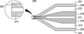
블록모듈하우징수단(100) 내부에 삽입, 위치되고, 제 3하우징블록부(130)의 제 1공기유동줄기(132)와 접하여 제 3경로(R3)를 형성하는 제 2공기유동줄기(211)와, 상기 제 2접착제원료유동줄기(133)와 접하여 제 2경로(R2)를 형성하는 제 3접착제원료유동줄기(212)를 생성, 제 2공기유동줄기(211)로부터는 공기가, 제 3접착제원료유동줄기(212)로부터는 접착제 원료가 유동되도록 하는 공기접착제토출유도니플모듈(210);The second air flow stem 211 inserted and positioned inside the block module housing means 100 and contacts the first air flow stem 132 of the third
상기 공기접착제토출유도니플모듈(210)이 내삽되도록 블록모듈하우징수단(100) 내부에 삽입, 위치되고, 내주연으로는 제 3접착제원료유동줄기(212)를 따라 제 2경로(R2)를 통해 접착제 원료가 유동되도록 하고, 외주연으로는 제 5하우징블록부(150) 및 이중튜브압출다이블록부(160)와의 결합으로 제 1경로(R1)를 형성하는 제 5외피수지원료유동줄기(151)와, 제 6외피수지원료유동줄기(221)가 생성되도록 하는 외피수지토출유도니플모듈(220);로 구성되어,The air adhesive discharge
외피 수지 원료와, 접착제 원료 및 공기가 각각의 경로를 통해 토출되도록 함으로서, 이중튜브압출구(161)로부터 외피 수지층(Po)과 접착제층(Pa)으로 형성된 열수축 접착 이중튜브(Tu)가 압출되도록 한다.By allowing the shell resin raw material, the adhesive raw material, and air to be discharged through each path, the heat-shrinkable adhesive double tube (Tu) formed of the skin resin layer (Po) and the adhesive layer (Pa) is extruded from the double
좀 더 상세하게는,In more detail,
공기접착제토출유도니플모듈(210)은,The air adhesive discharge
제 4하우징블록부(140), 제 5하우징블록부(150), 이중튜브압출다이블록부(160)에 걸쳐 위치되도록 삽입, 결합되고,Inserted and coupled to be positioned across the fourth
외피수지토출유도니플모듈(220)은,The outer cover resin discharge
상기 공기접착제토출유도니플모듈(210)의 일부가 내삽되어, 제 5하우징블록부(150), 이중튜브압출다이블록부(160)에 걸쳐 위치되도록 삽입, 결합된다.A part of the air adhesive discharge
즉, 공기접착제토출유도니플모듈(210)의 내부로는 공기가,That is, air is inside the air adhesive discharge
공기접착제토출유도니플모듈(210)의 외주연과, 외피수지토출유도니플모듈(220)의 내주연 사이에 생성되는 공간에는 접착제 원료가,In the space created between the outer periphery of the air adhesive discharge
외피수지토출유도니플모듈(220)의 외주연과, 제 5하우징블록부(150) 및 이중튜브압출다이블록부(160)의 내주연 사이에 생성되는 공간에는 외피 수지 원료가 유동된다.The outer periphery of the outer periphery of the outer periphery of the outer periphery of the outer periphery of the outer periphery of the outer periphery of the outer periphery of the outer periphery of the outer periphery of the outer periphery of the outer periphery of the outer periphery of the outer periphery of the outer periphery of the outer periphery of the outer shell resin discharge
이때, 공기접착제토출유도니플모듈(210)의 선단부에는 접착제막힘방지유동경로확대요소(213);가 더 포함, 구성되어,At this time, at the front end of the air adhesive discharge
압출되는 튜브(Tu)의 막힘을 방지하고, 접착제 원료가 외피 수지층(Po) 내주연에 균일하게 코팅되어 접착제층(Pa)을 형성할 수 있도록 한다.It prevents clogging of the extruded tube (Tu), and allows the adhesive raw material to be uniformly coated on the inner circumference of the outer resin layer (Po) to form the adhesive layer (Pa).
즉, 접착제 원료가 제 2경로(R2)를 따라 유동하면서, 이중튜브압출구(161)를 통해 압출될 시, 제 3경로(R3)를 따라 토출되어 생성되는 공기(공기 기둥)에 밀접하게 위치하여 압출되지 않고, 공기(공기 기둥)와 일정 간격 이격되어 압출되도록 함으로서, 튜브(Tu)의 막힘은 물론, 외피 수지층(Po) 내주연에 접착제 원료가 밀착되어 압출되도록 하기 위함이다.That is, when the adhesive raw material flows along the second path (R2) and is extruded through the double
또한, 상기 접착제막힘방지유동경로확대요소(211)와 대응되도록 외피수지토출유도니플모듈(220)의 선단부에는 접착제균등분포유도테이퍼요소(222);가 더 포함, 구성되고,In addition, a
이는, 접착제막힘방지유동경로확대요소(211)의 역할과 동일하게, 튜브(Tu)의 막힘을 방지하고, 접착제 원료가 외피 수지층(Po)에 균일하게 점착되어 접착제층(Pa)이 형성되도록 하기 위함이다.This, in the same way as the role of the adhesive clogging prevention flow
한편, 외피 수지층(Po)의 내주연을 기준으로 접착제층(Pa)이 편심되어 형성될 시에, 이를 조절하는 접착제편심방지수단(300)은,On the other hand, when the adhesive layer (Pa) is eccentrically formed based on the inner periphery of the outer resin layer (Po), the adhesive eccentricity preventing means 300 for controlling this,
제 4하우징블록부(140)의 일측에 형성되어, 제 4하우징블록부(140)의 위치를 미세하게 조정, 외피 수지층(Po)의 내주연에 도포되는 접착제 원료의 편심을 방지하는 제 1접착제편심방지조절부(310);The first is formed on one side of the fourth
이중튜브압출다이블록부(160)의 일측에 형성되어, 이중튜브압출다이블록부(160)의 위치를 미세하게 조정, 상기 제 1접착제편심방지조절부(310)와 같이 외피 수지층(Po)의 내주연에 도포되는 접착제 원료의 편심을 방지하는 제 2접착제편심방지조절부(320);로 구성되어,It is formed on one side of the double tube extrusion die
외피 수지층(Po) 내주연에 도포되는 접착제 원료의 편심을 2중으로 방지, 균일한 접착제층(Pa)이 형성되도록 함은 물론, 나아가, 외피 수지층(Po)과 접착제층(Pa)으로 형성된 열수축 접착 이중튜브(Tu)가 연속적으로 압출될 시에, 튜브(Tu) 자체가 편심되어 압출되는 것을 방지할 수 있다.Double prevention of the eccentricity of the adhesive raw material applied to the inner periphery of the outer resin layer (Po), allowing a uniform adhesive layer (Pa) to be formed, and furthermore, formed of the outer resin layer (Po) and the adhesive layer (Pa). When the heat-shrinkable adhesive double tube (Tu) is continuously extruded, the tube (Tu) itself can be prevented from being eccentrically extruded.
간단한 실시 예로, 접착제편심방지수단(300)을, 주하우징수단(H)을 관통, 각각 제 4하우징블록부(140)와 이중튜브압출다이블록부(160)의 외주연에 접촉되어 위치되는 미세조절용볼트(T)로 구성하여, 미세조절용볼트(T)를 이용, 제 4하우징블록부(140)와 이중튜브압출다이블록부(160)의 위치를 미세하게 조절할 수 있도록 한다.In a simple embodiment, the adhesive eccentricity preventing means 300, penetrating the main housing means (H), respectively, in contact with the outer periphery of the fourth
한편, 본 발명인 외피 수지층과 접착제층으로 이루어진 열수축 접착 이중튜브 압출 장치(1)에는,On the other hand, in the heat-shrinkable adhesive double
블록모듈하우징수단(100)의 각각의 하우징블록부(110 내지 160)의 일측에 형성되어, 각각의 하우징블록부(110 내지 160) 내부, 즉, 제 1경로(R1), 제 2경로(R2), 제 3경로(R3)의 압력을 실시간 확인하는 유동압력센싱수단(400);It is formed on one side of each housing block portion (110 to 160) of the block module housing means (100), inside each housing block portion (110 to 160), that is, the first path (R1), the second path (R2) ), flow pressure sensing means 400 for checking the pressure of the third path R3 in real time;
외피수지원료주입구(111), 접착제원료주입구(121), 공기주입구(131)의 일측에 각각 형성되어, 상기 유동압력센싱수단(400)에 의해 실시간 측정되는 각 경로의 압력이 각 경로에 적합한 적정 압력 이하 또는 적정 압력 이상일 경우, 외피수지원료주입구(111)와, 접착제원료주입구(121), 공기주입구(131)의 압력을 상승 또는 저하시켜, 각 경로의 압출 속도가 정상적으로 회복되도록 하는 적정압출압력조절수단(500);이 더 포함, 구성되어,It is formed on one side of the outer cover
압출되는 튜브(Tu)의 불량률 감소를 극대화하고, 압출 장치를 실시간 모니터링 할 수 있도록 함으로서, 압출 장치의 휴지(休止)를 최소화하고, 연속적인 압출 작업이 이루어지도록 도모할 수 있다.(즉, 생산성을 극대화할 수 있다.)By maximizing the reduction of the defect rate of the extruded tube (Tu) and allowing the extrusion device to be monitored in real time, it is possible to minimize the idleness of the extrusion device and to achieve a continuous extrusion operation (that is, productivity). Can be maximized.)
이때, 적정압출압력조절수단(500)은,At this time, the appropriate extrusion pressure control means 500,
예를 들어, 밸브로 형성되거나, 블로어 또는 컴프레서의 출력을 조절할 수 있는 인버터 등으로 적용될 수 있다.For example, it may be formed as a valve, or applied as an inverter capable of controlling the output of a blower or a compressor.
한편, 본 발명인 외피 수지층과 접착제층으로 이루어진 열수축 접착 이중튜브 압출 장치(1)를 이용한 튜브(Tu)의 생산 공정은,On the other hand, the production process of the tube (Tu) using the heat-shrinkable adhesive double
도 7에 도시된 바와 같이,As shown in Figure 7,
a) 압출 장치(1)를 이용하여 외피 수지층(Po)을 외장으로 외피 수지층(Po) 내주연에 접착제층(Pa)을 형성하여, 외피 수지층(Po)과 접착제층(Pa)으로 형성된 열수축 접착 이중 튜브(Tu)를 압출하는 이중튜브압출단계(S100);a) Using an extrusion device (1), an adhesive layer (Pa) was formed on the inner periphery of the outer resin layer (Po) by using the outer resin layer (Po) to form the outer resin layer (Po) and the adhesive layer (Pa). Double tube extrusion step (S100) of extruding the formed heat-shrinkable adhesive double tube (Tu);
b) 상기 'a)' 단계 후의 튜브(Tu)를 가교시키는 조사단계(S200);b) an irradiation step (S200) of crosslinking the tube (Tu) after step'a)';
c) 상기 'b)' 단계 후의 튜브(Tu)를 소정의 직경으로 팽창시키는 팽창단계(S300);c) an expansion step (S300) of expanding the tube (Tu) after step'b)' to a predetermined diameter;
d) 상기 'c)' 단계 후의 튜브(Tu)를 절단기를 이용하여 일정 간격으로 절단하는 절단단계(S400);d) a cutting step (S400) of cutting the tube (Tu) after step'c)' at regular intervals using a cutter;
e) 상기 'd)' 단계 후, 일정 간격으로 절단된 튜브(Tu)에 대한 불량 여부를 검사하는 검사단계(S500);로 구성된다.e) After the'd)' step, an inspection step (S500) of inspecting whether or not the tube (Tu) is cut at regular intervals is defective.
즉, 상술한 상기 튜브(Tu)의 생산 공정은,That is, the production process of the tube (Tu) described above,
본 발명의 압출 장치(1)를 이용하여 외피 수지층(Po)과 접착제층(Pa)으로 형성된 열수축 접착 이중튜브(Tu)를 압출하고,Extruding the heat-shrinkable adhesive double tube (Tu) formed of the outer resin layer (Po) and the adhesive layer (Pa) using the
조사기를 이용하여 상기 튜브(Tu)를 가교, 소정의 직경으로 팽창시켜,Crosslinking the tube (Tu) using an irradiator and expanding it to a predetermined diameter,
절단기를 이용, 상기 튜브(Tu)를 일정 간격으로 절단한 후, 불량 여부를 검사하는 공정을 단계로 나타낸 것이다.After cutting the tube (Tu) at regular intervals using a cutter, the process of inspecting for defects is shown in steps.
이처럼, 본 발명인 외피 수지층과 접착제층으로 이루어진 열수축 접착 이중튜브 압출 장치(1)는,As described above, the heat-shrinkable double-
외피 수지층(Po)과 접착제층(Pa)으로 형성된 열수축 접착 이중튜브(Tu) 압출 작업 시, 내, 외피 편심에 대한 수정 및 보완이 가능하고, 튜브(Tu)의 막힘을 방지, 접착제 원료가 외피 수지층(Po) 내주연에 균일, 균등하게 도포되도록 하여, 미도포를 방지하는 생산 시스템을 구축할 수 있도록 하기 위한 것이다.When extruding a heat-shrinkable adhesive double tube (Tu) formed of an outer resin layer (Po) and an adhesive layer (Pa), it is possible to correct and supplement the eccentricity of the inner and outer outer layers, and prevent clogging of the tube (Tu). The purpose is to establish a production system that prevents non-application by making it uniformly and evenly applied to the inner periphery of the outer resin layer (Po).
즉, 제 3경로(R3)를 통해 토출되는 공기(공기 기둥)와, 접착제막힘방지유동경로확대요소(211), 접착제균등분포유도테이퍼요소(221)의 형성으로 튜브(Tu)가 폐쇄되는 것을 방지하고,That is, the formation of the air (air column) discharged through the third path R3, the flow
접착제편심방지수단(300)의 미세한 조정으로, 튜브(Tu)의 내, 외피 편심 및 특히, 내피인 접착제층(Pa)의 편심을 방지, 품질이 일정한 튜브(Tu)가 생산되도록 한다.By fine adjustment of the adhesive eccentricity prevention means 300, the inner and outer skin eccentricity of the tube Tu, and in particular, the eccentricity of the adhesive layer Pa, which is the inner skin, is prevented, so that a tube of constant quality is produced.
한편, 본 발명인 외피 수지층과 접착제층으로 이루어진 열수축 접착 이중튜브 압출 장치(1)를 통해 압출되는 튜브(Tu)는,On the other hand, the tube (Tu) that is extruded through the heat-shrinkable adhesive double
외피 수지층(Po) 내주연에 형성된 접착제층(Pa)이 열에 의해 용융되어, 수밀 보호, 결속력 강화, 부식 방지의 효과가 발휘되도록 한다.The adhesive layer (Pa) formed on the inner periphery of the outer resin layer (Po) is melted by heat, so that the effects of watertight protection, strengthening of binding force, and corrosion prevention are exhibited.
즉, 튜브(Tu)에 열을 가하면, 일정 비율로 축소되면서 접착제층(Pa)이 용융되어, 밀봉, 방수된다.That is, when heat is applied to the tube (Tu), the adhesive layer (Pa) is melted, sealed, and waterproof while shrinking at a certain ratio.
특히, 본 발명은, 와이어, 케이블, 커넥터, 연료 파이프를 단단하게 고정할 수 있는 튜브(Tu)를 압출하기 위한 압출 장치(1)에 대한 것이다.In particular, the present invention relates to an
참고하여,For reference,
본 발명으로부터 압출되는 튜브(Tu)의 외피 수지층(Po)은,The outer resin layer (Po) of the tube (Tu) extruded from the present invention,
예를 들어, 폴리올레핀(Polyolefine),For example, polyolefine,
접착제층(Pa)은, 폴리아마이드(Polyamide)이다.The adhesive layer (Pa) is polyamide.
즉, 외피 수지층(Po)은 가교 폴리올레핀(Polyolefine) 수지를 외장으로 하고,In other words, the outer resin layer (Po) is made of a crosslinked polyolefine resin as an exterior,
접착제층(Pa)은 열가소성 접착제를 내장으로 하여 치수 및 표면이 균일하게 도포하는 생산 시스템이 구축되도록 한다.The adhesive layer (Pa) has a thermoplastic adhesive embedded therein to establish a production system that uniformly applies dimensions and surfaces.
또한, 본 발명으로부터 압출되는 튜브(Tu)는, 금속과 파이프 마찰에 의한 소음 및 진동을 방지한다.In addition, the tube (Tu) extruded from the present invention prevents noise and vibration due to friction between metal and pipe.
또한, 본 발명인 압출 장치(1)는 표면 열처리하여, 열변형을 방지하고, 주입되는 각 원료(외피 수지 원료, 접착제 원료, 공기)의 흐름성을 고려하여 내부는 크롬 도금이 적용되는 것이 바람직하다.In addition, it is preferable that the
이상에서와 같이, 본 발명은 기재된 실시 예에 한정되는 것이 아니고, 본 발명의 사상 및 범위를 벗어나지 않고 다양하게 수정 및 변형할 수 있음은 이 기술의 분야에서 통상의 지식을 가진 자에게 자명하다.As described above, it is apparent to those of ordinary skill in the art that the present invention is not limited to the described embodiments, and that various modifications and variations can be made without departing from the spirit and scope of the present invention.
따라서, 기술적 사상 또는 주요한 특징으로부터 벗어남이 없이 다른 여러가지 형태로 실시될 수 있으므로, 본 발명의 실시 예들은 모든 점에서 단순한 예시에 지나지 않으며 한정적으로 해석되어서는 아니되며 다양하게 변형하여 실시할 수 있다.Therefore, since it can be implemented in various forms without departing from the technical idea or main characteristics, the embodiments of the present invention are merely illustrative in all respects and should not be interpreted as limiting, and various modifications may be made.
본 발명은 외피 수지층과 접착제층으로 이루어진 열수축 접착 이중튜브 압출 장치에 관한 것으로서, 이를 제작하는 제작, 제조업 및 판매업, 즉, 전기, 전자, 무선, 통신 분야가 구현하는 시스템을 구축함에 있어 사용되는 다양한 전선을 보호할 필요성이 있는, 전선과 관련된 다양한 산업분야 증진에 기여하는 데에 적용할 수 있으며,The present invention relates to a heat-shrink-adhesive double tube extrusion device consisting of an outer shell resin layer and an adhesive layer, and is used in constructing a system implemented in the manufacturing, manufacturing and sales industries, that is, electric, electronic, wireless, and communication fields. It can be applied to contribute to the promotion of various industrial fields related to electric wires that need to protect various electric wires,
특히, 자동차 브레이크 파이프, 연료 파이프의 부식 및 외부 충격으로부터 소자를 보호하기 위한 목적으로 사용되는 열수축 접착 튜브를 생산하는 튜브 제조, 생산 산업분야에 기여할 수 있다.In particular, it can contribute to the field of manufacturing and production of tubes that produce heat-shrinkable adhesive tubes used for the purpose of protecting elements from corrosion and external impacts of automobile brake pipes and fuel pipes.
1: 외피 수지층과 접착제층으로 이루어진 열수축 접착 이중튜브 압출 장치
100: 블록모듈하우징수단 110: 제 1하우징블록부
111: 외피수지원료주입구 112: 제 1외피수지원료유동줄기
120: 제 2하우징블록부 121: 접착제원료주입구
122: 제 1접착제원료유동줄기 123: 제 2외피수지원료유동줄기
130: 제 3하우징블록부 131: 공기주입구
132: 제 1공기유동줄기 133: 제 2접착제원료유동줄기
134: 제 3외피수지원료유동줄기 140: 제 4하우징블록부
141: 제 4외피수지원료유동줄기 150: 제 5하우징블록부
151: 제 5외피수지원료유동줄기 160: 이중튜브압출다이블록부
161: 이중튜브압출구
200: 유입물질유도니플수단 210: 공기접착제토출유도니플모듈
211: 제 2공기유동줄기 212: 제 3접착제원료유동줄기
213: 접착제막힘방지유동경로확대요소
220: 외피수지토출유도니플모듈
221: 제 6외피수지원료유동줄기 222: 접착제균등분포유도테이퍼요소
300: 접착제편심방지수단 310: 제 1접착제편심방지조절부
320: 제 2접착제편심방지조절부
400: 유동압력센싱수단 500: 적정압출압력조절수단
S100: 이중튜브압출단계 S200: 조사단계
S300: 팽창단계 S400: 절단단계
S500: 검사단계
B: 원료유동경로확보모듈 H: 주하우징수단
T: 미세조절용볼트
R1: 제 1경로 R2: 제 2경로
R3: 제 3경로
Po: 외피 수지층 Pa: 접착제층
Tu: 외피 수지층(Po)과 접착제층(Pa)으로 형성된 열수축 접착 이중튜브1: Heat-shrink adhesive double tube extrusion device consisting of a resin layer and an adhesive layer
100: block module housing means 110: first housing block unit
111: sheath fee injection port 112: the first sheath fee flow stream
120: second housing block part 121: adhesive raw material injection port
122: the first adhesive material flow stem 123: the second outer shell material flow stem
130: third housing block part 131: air inlet
132: first air flow stem 133: second adhesive raw material flow stem
134: 3rd sheath fee flow stem 140: 4th housing block part
141: 4th sheath fee flow stem 150: 5th housing block part
151: 5th sheathing fee flow stem 160: double tube extrusion die block portion
161: double tube extrusion port
200: inflow material induction nipple means 210: air adhesive discharge induction nipple module
211: second air flow stem 212: third adhesive raw material flow stem
213: Adhesive clogging prevention flow path expansion factor
220: sheath resin discharge induction nipple module
221: 6th sheathing fee flow stem 222: tapered element inducing even distribution of adhesive
300: adhesive eccentricity prevention means 310: first adhesive eccentricity prevention control unit
320: second adhesive eccentricity prevention control unit
400: flow pressure sensing means 500: appropriate extrusion pressure control means
S100: double tube extrusion step S200: irradiation step
S300: expansion step S400: cutting step
S500: Inspection step
B: Material flow path securing module H: Main housing means
T: fine adjustment bolt
R1: first path R2: second path
R3:
Po: outer resin layer Pa: adhesive layer
Tu: Heat-shrinkable double tube formed of outer resin layer (Po) and adhesive layer (Pa)
Claims (2)
주하우징수단(H);
상기 주하우징수단(H) 내부에 삽입, 위치되되, 분할 구조로 형성되고, 외피 수지 원료와 접착제 원료 및 공기가 각각 유입되어, 외피 수지층(Po)과 접착제층(Pa)으로 형성된 열수축 접착 이중튜브(Tu)가 압출되도록 하는 블록모듈하우징수단(100);
상기 블록모듈하우징수단(100) 내부에 위치, 결합되고, 블록모듈하우징수단(100) 내부로 유입되는 외피 수지 원료와, 접착제 원료 및 공기가 각각의 유로(流路)를 통해 유동되도록 하는 유입물질유도니플수단(200);
상기 블록모듈하우징수단(100)의 일측에 형성되고, 압출되는 접착제의 편심을 방지하여, 외피 수지층(Po) 내주연에 도포되는 접착제가 균등하게 도포되어 균일한 접착제층(Pa)이 형성되도록 하는 접착제편심방지수단(300);으로 구성됨으로서,
외피 수지층(Po)과 접착제층(Pa)으로 형성된 열수축 접착 이중튜브(Tu)가 압출되도록 하되,
블록모듈하우징수단(100)은,
외피 수지층(Po)을 형성하기 위한 외피 수지 원료가 투입되는 외피수지원료주입구(111)와, 외피수지원료주입구(111)로 투입된 외피 수지 원료가 제 1경로(R1)를 따라 외부로 토출되도록 외피 수지 원료가 유동되는 제 1외피수지원료유동줄기(112)가 형성된 제 1하우징블록부(110);
접착제층(Pa)을 형성하기 위한 접착제 원료가 투입되는 접착제원료주입구(121)와, 접착제원료주입구(121)로 투입된 접착제 원료가 제 2경로(R2)를 따라 외부로 토출되도록 접착제 원료가 유동되는 제 1접착제원료유동줄기(122) 및 상기 제 1외피수지원료유동줄기(112)와 접하여 제 1경로(R1)를 형성하는 제 2외피수지원료유동줄기(123)가 형성된 제 2하우징블록부(120);
공기가 투입되는 공기주입구(131)와, 공기주입구(131)로 투입된 공기가 제 3경로(R3)를 따라 외부로 토출되도록 공기가 유동되는 제 1공기유동줄기(132), 상기 제 1접착제원료유동줄기(122)와 접하여 제 2경로(R2)를 형성하는 제 2접착제원료유동줄기(133) 및 상기 제 2외피수지원료유동줄기(123)와 접하여 제 1경로(R1)를 형성하는 제 3외피수지원료유동줄기(134)가 형성된 제 3하우징블록부(130);
일측에 접착제편심방지수단(300)이 형성되고, 상기 제 3외피수지원료유동줄기(134)와 접하여 제 1경로(R1)를 형성하는 제 4외피수지원료유동줄기(141)가 형성된 제 4하우징블록부(140);
상기 제 4외피수지원료유동줄기(141)와 접하여 제 1경로(R1)를 형성하는 제 5외피수지원료유동줄기(151)가 형성된 제 5하우징블록부(150);
일측에 접착제편심방지수단(300)이 형성되고, 각각의 원료가 각각의 경로를 통해 유동되어, 외피 수지층과 접착제층으로 형성된 열수축 접착 이중튜브(Tu)가 압출되도록 하는 이중튜브압출구(161)가 형성된 이중튜브압출다이블록부(160);로 구성되되,
분할 구조로 이루어져, 제 1하우징블록부(110), 제 2하우징블록부(120), 제 3하우징블록부(130), 제 4하우징블록부(140), 제 5하우징블록부(150), 이중튜브압출다이블록부(160)가 순차적으로 결합, 분리되도록 하고,
제 1하우징블록부(110)로 외피 수지 원료가, 제 2하우징블록부(120)로 접착제 원료가, 제 3하우징블록부(130)로 공기가 각각 투입되어,
이중튜브압출구(161)로부터 외피 수지층(Po)과 접착제층(Pa)으로 형성된 열수축 접착 이중튜브(Tu)가 연속적으로 압출되는 것을 특징으로 하는,
외피 수지층과 접착제층으로 이루어진 열수축 접착 이중튜브 압출 장치.In the heat-shrink-adhesive double tube extrusion device (1) consisting of a shell resin layer and an adhesive layer,
Main housing means (H);
Inserted and positioned inside the main housing means (H), it is formed in a divided structure, and the outer shell resin raw material, the adhesive raw material, and air are introduced respectively, and the heat shrinkable adhesive double formed of the outer resin layer (Po) and the adhesive layer (Pa) Block module housing means 100 to allow the tube (Tu) to be extruded;
An inlet material that is positioned and coupled to the inside of the block module housing means 100 and allows the skin resin raw material, the adhesive raw material and air to flow into the block module housing means 100 through each flow path Induction nipple means 200;
It is formed on one side of the block module housing means 100 and prevents eccentricity of the extruded adhesive, so that the adhesive applied to the inner periphery of the outer resin layer (Po) is evenly applied to form a uniform adhesive layer (Pa). As consisting of an adhesive eccentricity prevention means 300;
The heat shrinkable adhesive double tube (Tu) formed of the outer resin layer (Po) and the adhesive layer (Pa) is extruded,
Block module housing means 100,
So that the skin resin raw material injection port 111 into which the skin resin raw material for forming the skin resin layer (Po) is injected, and the skin resin raw material injected through the skin water support material injection port 111 are discharged to the outside along the first path (R1). A first housing block portion 110 in which a first shell material flow stem 112 through which the shell resin raw material flows is formed;
The adhesive raw material flows so that the adhesive raw material injection port 121 into which the adhesive raw material for forming the adhesive layer Pa is injected, and the adhesive raw material injected through the adhesive raw material injection port 121 are discharged to the outside along the second path R2. The second housing block portion in which the first adhesive raw material flow stem 122 and the second enveloped raw material flow stem 123 are formed to form a first path R1 in contact with the first enveloped raw material flow stem 112 ( 120);
An air inlet 131 into which air is injected, a first air flow stem 132 through which air flows so that the air injected into the air inlet 131 is discharged to the outside along the third path R3, the first adhesive material The second adhesive raw material flow stem 133 in contact with the flow stem 122 to form a second path R2 and the third material flow stem 133 in contact with the second sheath water support material flow stem 123 to form a first path R1 A third housing block unit 130 in which the sheath fee flow stem 134 is formed;
A fourth housing having an adhesive eccentric prevention means 300 formed on one side, and having a fourth enveloped support material flow stem 141 forming a first path R1 in contact with the third enveloped support material flow stem 134 A block unit 140;
A fifth housing block unit 150 in which a fifth casing fee flow stem 151 is formed in contact with the fourth casing fee flow stem 141 to form a first path R1;
The adhesive eccentricity prevention means 300 is formed on one side, and each raw material flows through each path, so that the heat shrinkable adhesive double tube (Tu) formed of the outer resin layer and the adhesive layer is extruded. ) Is formed of a double tube extrusion die block unit 160; consisting of,
It consists of a divided structure, the first housing block unit 110, the second housing block unit 120, the third housing block unit 130, the fourth housing block unit 140, the fifth housing block unit 150, The double tube extrusion die block unit 160 is sequentially combined and separated,
The first housing block unit 110 is supplied with a raw resin material, the second housing block unit 120 is supplied with an adhesive raw material, and the third housing block unit 130 is supplied with air, respectively,
Characterized in that the heat-shrinkable double tube (Tu) formed of the outer shell resin layer (Po) and the adhesive layer (Pa) is continuously extruded from the double tube extrusion port 161,
Heat-shrinkable double tube extrusion device consisting of a resin layer and an adhesive layer.
Priority Applications (1)
| Application Number | Priority Date | Filing Date | Title |
|---|---|---|---|
| KR1020190164729A KR102204970B1 (en) | 2019-12-11 | 2019-12-11 | Extruder of heat-shrinkable tube |
Applications Claiming Priority (1)
| Application Number | Priority Date | Filing Date | Title |
|---|---|---|---|
| KR1020190164729A KR102204970B1 (en) | 2019-12-11 | 2019-12-11 | Extruder of heat-shrinkable tube |
Publications (1)
| Publication Number | Publication Date |
|---|---|
| KR102204970B1 true KR102204970B1 (en) | 2021-01-19 |
Family
ID=74237365
Family Applications (1)
| Application Number | Title | Priority Date | Filing Date |
|---|---|---|---|
| KR1020190164729A Active KR102204970B1 (en) | 2019-12-11 | 2019-12-11 | Extruder of heat-shrinkable tube |
Country Status (1)
| Country | Link |
|---|---|
| KR (1) | KR102204970B1 (en) |
Cited By (1)
| Publication number | Priority date | Publication date | Assignee | Title |
|---|---|---|---|---|
| CN114396510A (en) * | 2022-01-19 | 2022-04-26 | 重庆泓一科技有限公司 | Continuous fiber woven internal reinforced PVC-C composite pipeline and preparation method thereof |
Citations (7)
| Publication number | Priority date | Publication date | Assignee | Title |
|---|---|---|---|---|
| KR930016228A (en) * | 1992-01-04 | 1993-08-26 | 박원근 | Adhesive thin layer coating method in extrusion tube and apparatus therefor |
| KR100632415B1 (en) | 2005-01-26 | 2006-10-13 | 주식회사 삼광기공 | Heat Shrink Tubing Manufacturing Equipment |
| KR20080051364A (en) * | 2006-12-05 | 2008-06-11 | 엘에스전선 주식회사 | Adhesive coating apparatus and manufacturing method of heat shrinkable tube using the apparatus |
| KR20080109114A (en) * | 2007-06-12 | 2008-12-17 | 김용재 | Manufacturing apparatus and method of heat shrinkable resin tube for steel pipe coating |
| CN204673990U (en) * | 2015-05-27 | 2015-09-30 | 东莞三联热缩材料有限公司 | A kind of single wall heat-shrinkable T bush extrudes no-mould adjusted tool |
| JP6581633B2 (en) * | 2017-09-12 | 2019-09-25 | 株式会社協成 | Manufacturing method of resin-coated steel pipe |
| KR20200029938A (en) * | 2018-09-11 | 2020-03-19 | 임근학 | Heat-shrinkable tube and method for producing same |
-
2019
- 2019-12-11 KR KR1020190164729A patent/KR102204970B1/en active Active
Patent Citations (8)
| Publication number | Priority date | Publication date | Assignee | Title |
|---|---|---|---|---|
| KR930016228A (en) * | 1992-01-04 | 1993-08-26 | 박원근 | Adhesive thin layer coating method in extrusion tube and apparatus therefor |
| KR100632415B1 (en) | 2005-01-26 | 2006-10-13 | 주식회사 삼광기공 | Heat Shrink Tubing Manufacturing Equipment |
| KR20080051364A (en) * | 2006-12-05 | 2008-06-11 | 엘에스전선 주식회사 | Adhesive coating apparatus and manufacturing method of heat shrinkable tube using the apparatus |
| KR100853896B1 (en) | 2006-12-05 | 2008-08-25 | 엘에스전선 주식회사 | Adhesive coating apparatus and manufacturing method of heat shrinkable tube using the apparatus |
| KR20080109114A (en) * | 2007-06-12 | 2008-12-17 | 김용재 | Manufacturing apparatus and method of heat shrinkable resin tube for steel pipe coating |
| CN204673990U (en) * | 2015-05-27 | 2015-09-30 | 东莞三联热缩材料有限公司 | A kind of single wall heat-shrinkable T bush extrudes no-mould adjusted tool |
| JP6581633B2 (en) * | 2017-09-12 | 2019-09-25 | 株式会社協成 | Manufacturing method of resin-coated steel pipe |
| KR20200029938A (en) * | 2018-09-11 | 2020-03-19 | 임근학 | Heat-shrinkable tube and method for producing same |
Cited By (2)
| Publication number | Priority date | Publication date | Assignee | Title |
|---|---|---|---|---|
| CN114396510A (en) * | 2022-01-19 | 2022-04-26 | 重庆泓一科技有限公司 | Continuous fiber woven internal reinforced PVC-C composite pipeline and preparation method thereof |
| CN114396510B (en) * | 2022-01-19 | 2024-02-20 | 重庆泓一科技有限公司 | Continuous fiber woven internal reinforced PVC-C composite pipeline and preparation method thereof |
Similar Documents
| Publication | Publication Date | Title |
|---|---|---|
| AU2016429081B2 (en) | Process for jointing cables, apparatus for performing such a process and thermoplastic joint so manufactured | |
| US6688339B2 (en) | Composite high-pressure tube and method of manufacturing the tube | |
| FI112819B (en) | Collar and method for forming a composite collar | |
| US4341578A (en) | Method of hose production | |
| US20150260326A1 (en) | Electrically heatable media line, and method for producing such a media line | |
| KR20000065088A (en) | Multilayer reinforced and stabilized cable construction | |
| KR102204970B1 (en) | Extruder of heat-shrinkable tube | |
| KR100533366B1 (en) | Connecting pipe embeded with heating coil for plastic pipes and method for producing the same | |
| GB2034433A (en) | Method of hose production and product | |
| AU738453B2 (en) | Optical cable with tubular metal core | |
| CN113725804B (en) | Cable, cable flexible joint, insulation recovery method, mold and detection method thereof | |
| US8491744B2 (en) | Method for the production of a cylindrical, strand-shaped part | |
| DK157098B (en) | PROCEDURE FOR MAKING A HEAT-INSULATED CONNECTOR | |
| CN104700946B (en) | Manufacturing method of special-shaped filling rope for optical cable or electric cable or photoelectric composite cable or photoelectric composite cable | |
| CN212297983U (en) | High-pressure composite pipe and processing equipment thereof | |
| CN117878813A (en) | Submarine cable cabin sealing assembly, optoelectronic composite cable and submarine cable cabin entry method | |
| JP3022064B2 (en) | Wire harness integrated grommet and molding method thereof | |
| JPH03149485A (en) | Multiple-unit tube | |
| JP4248652B2 (en) | Optical cable manufacturing method and manufacturing apparatus | |
| RU2843297C1 (en) | Multilayer antistatic flexible polymer sleeve and method of production thereof | |
| CN112856057B (en) | Continuous fiber glass fiber board stirrup pipe composite arc top triangular corrugated pipeline | |
| WO2014177230A1 (en) | Insulated conductor assembly and method of its manufacturing | |
| KR20050082120A (en) | A plastic pipe connecter that heat contractions are possible | |
| PL241756B1 (en) | Method of producing a multilayer pipe | |
| KR20080057431A (en) | Integrated pipe molding injection device |
Legal Events
| Date | Code | Title | Description |
|---|---|---|---|
| PA0109 | Patent application |
St.27 status event code: A-0-1-A10-A12-nap-PA0109 |
|
| PA0201 | Request for examination |
St.27 status event code: A-1-2-D10-D11-exm-PA0201 |
|
| D13-X000 | Search requested |
St.27 status event code: A-1-2-D10-D13-srh-X000 |
|
| D14-X000 | Search report completed |
St.27 status event code: A-1-2-D10-D14-srh-X000 |
|
| E902 | Notification of reason for refusal | ||
| PE0902 | Notice of grounds for rejection |
St.27 status event code: A-1-2-D10-D21-exm-PE0902 |
|
| E13-X000 | Pre-grant limitation requested |
St.27 status event code: A-2-3-E10-E13-lim-X000 |
|
| P11-X000 | Amendment of application requested |
St.27 status event code: A-2-2-P10-P11-nap-X000 |
|
| P13-X000 | Application amended |
St.27 status event code: A-2-2-P10-P13-nap-X000 |
|
| E701 | Decision to grant or registration of patent right | ||
| PE0701 | Decision of registration |
St.27 status event code: A-1-2-D10-D22-exm-PE0701 |
|
| GRNT | Written decision to grant | ||
| PR0701 | Registration of establishment |
St.27 status event code: A-2-4-F10-F11-exm-PR0701 |
|
| PR1002 | Payment of registration fee |
St.27 status event code: A-2-2-U10-U11-oth-PR1002 Fee payment year number: 1 |
|
| PG1601 | Publication of registration |
St.27 status event code: A-4-4-Q10-Q13-nap-PG1601 |
|
| PR1001 | Payment of annual fee |
St.27 status event code: A-4-4-U10-U11-oth-PR1001 Fee payment year number: 4 |
|
| PR1001 | Payment of annual fee |
St.27 status event code: A-4-4-U10-U11-oth-PR1001 Fee payment year number: 5 |
|
| PR1001 | Payment of annual fee |
St.27 status event code: A-4-4-U10-U11-oth-PR1001 Fee payment year number: 6 |
|
| U11 | Full renewal or maintenance fee paid |
Free format text: ST27 STATUS EVENT CODE: A-4-4-U10-U11-OTH-PR1001 (AS PROVIDED BY THE NATIONAL OFFICE) Year of fee payment: 6 |