KR102151652B1 - Using Cuk Converter topology Li-ion battery cell balancing strategy - Google Patents
Using Cuk Converter topology Li-ion battery cell balancing strategy Download PDFInfo
- Publication number
- KR102151652B1 KR102151652B1 KR1020190022495A KR20190022495A KR102151652B1 KR 102151652 B1 KR102151652 B1 KR 102151652B1 KR 1020190022495 A KR1020190022495 A KR 1020190022495A KR 20190022495 A KR20190022495 A KR 20190022495A KR 102151652 B1 KR102151652 B1 KR 102151652B1
- Authority
- KR
- South Korea
- Prior art keywords
- battery cell
- battery
- inductance
- cell balancing
- capacitor
- Prior art date
- Legal status (The legal status is an assumption and is not a legal conclusion. Google has not performed a legal analysis and makes no representation as to the accuracy of the status listed.)
- Active
Links
Images


Classifications
-
- H02J7/0019—
-
- H—ELECTRICITY
- H02—GENERATION; CONVERSION OR DISTRIBUTION OF ELECTRIC POWER
- H02J—ELECTRIC POWER NETWORKS; CIRCUIT ARRANGEMENTS OR SYSTEMS FOR SUPPLYING OR DISTRIBUTING ELECTRIC POWER; SYSTEMS FOR STORING ELECTRIC ENERGY
- H02J7/00—Circuit arrangements for charging or discharging batteries or for supplying loads from batteries
- H02J7/50—Circuit arrangements for charging or discharging batteries or for supplying loads from batteries acting upon multiple batteries simultaneously or sequentially
- H02J7/52—Circuit arrangements for charging or discharging batteries or for supplying loads from batteries acting upon multiple batteries simultaneously or sequentially for charge balancing, e.g. equalisation of charge between batteries
- H02J7/56—Active balancing, e.g. using capacitor-based, inductor-based or DC-DC converters
-
- H—ELECTRICITY
- H01—ELECTRIC ELEMENTS
- H01M—PROCESSES OR MEANS, e.g. BATTERIES, FOR THE DIRECT CONVERSION OF CHEMICAL ENERGY INTO ELECTRICAL ENERGY
- H01M10/00—Secondary cells; Manufacture thereof
- H01M10/05—Accumulators with non-aqueous electrolyte
- H01M10/052—Li-accumulators
- H01M10/0525—Rocking-chair batteries, i.e. batteries with lithium insertion or intercalation in both electrodes; Lithium-ion batteries
-
- H—ELECTRICITY
- H02—GENERATION; CONVERSION OR DISTRIBUTION OF ELECTRIC POWER
- H02J—ELECTRIC POWER NETWORKS; CIRCUIT ARRANGEMENTS OR SYSTEMS FOR SUPPLYING OR DISTRIBUTING ELECTRIC POWER; SYSTEMS FOR STORING ELECTRIC ENERGY
- H02J3/00—Circuit arrangements for AC mains or AC distribution networks
- H02J3/28—Arrangements for balancing of the load in networks by storage of energy
- H02J3/32—Arrangements for balancing of the load in networks by storage of energy using batteries or super capacitors with converting means
-
- H—ELECTRICITY
- H02—GENERATION; CONVERSION OR DISTRIBUTION OF ELECTRIC POWER
- H02M—APPARATUS FOR CONVERSION BETWEEN AC AND AC, BETWEEN AC AND DC, OR BETWEEN DC AND DC, AND FOR USE WITH MAINS OR SIMILAR POWER SUPPLY SYSTEMS; CONVERSION OF DC OR AC INPUT POWER INTO SURGE OUTPUT POWER; CONTROL OR REGULATION THEREOF
- H02M3/00—Conversion of DC power input into DC power output
- H02M3/005—Conversion of DC power input into DC power output using Cuk converters
-
- H—ELECTRICITY
- H01—ELECTRIC ELEMENTS
- H01M—PROCESSES OR MEANS, e.g. BATTERIES, FOR THE DIRECT CONVERSION OF CHEMICAL ENERGY INTO ELECTRICAL ENERGY
- H01M10/00—Secondary cells; Manufacture thereof
- H01M10/42—Methods or arrangements for servicing or maintenance of secondary cells or secondary half-cells
- H01M10/425—Structural combination with electronic components, e.g. electronic circuits integrated to the outside of the casing
- H01M2010/4271—Battery management systems including electronic circuits, e.g. control of current or voltage to keep battery in healthy state, cell balancing
-
- Y—GENERAL TAGGING OF NEW TECHNOLOGICAL DEVELOPMENTS; GENERAL TAGGING OF CROSS-SECTIONAL TECHNOLOGIES SPANNING OVER SEVERAL SECTIONS OF THE IPC; TECHNICAL SUBJECTS COVERED BY FORMER USPC CROSS-REFERENCE ART COLLECTIONS [XRACs] AND DIGESTS
- Y02—TECHNOLOGIES OR APPLICATIONS FOR MITIGATION OR ADAPTATION AGAINST CLIMATE CHANGE
- Y02E—REDUCTION OF GREENHOUSE GAS [GHG] EMISSIONS, RELATED TO ENERGY GENERATION, TRANSMISSION OR DISTRIBUTION
- Y02E60/00—Enabling technologies; Technologies with a potential or indirect contribution to GHG emissions mitigation
- Y02E60/10—Energy storage using batteries
Landscapes
- Engineering & Computer Science (AREA)
- Power Engineering (AREA)
- Chemical & Material Sciences (AREA)
- Materials Engineering (AREA)
- Manufacturing & Machinery (AREA)
- Chemical Kinetics & Catalysis (AREA)
- Electrochemistry (AREA)
- General Chemical & Material Sciences (AREA)
- Charge And Discharge Circuits For Batteries Or The Like (AREA)
- Secondary Cells (AREA)
Abstract
본 발명은 척컨버터 토폴로지를 이용한 리튬이온 전지 셀밸런싱 장치에 관한 것으로서, 더욱 상세하게는 승강압제어가 가능하고 연속적인 에너지의 흐름을 보장하는 비절연 컨버터방식의 척컨버터(Cuk Converter)를 이용하여 배터리 보호시스템의 안정화와 전체시스템의 신뢰성을 확보하고자 하는 척컨버터 토폴로지를 이용한 리튬이온 전지 셀밸런싱 장치에 관한 것이다.The present invention relates to a lithium-ion battery cell balancing device using a chuck converter topology, and more particularly, by using a non-isolated converter type chuck converter (Cuk Converter) that enables step-up and voltage control and ensures a continuous flow of energy. The present invention relates to a lithium ion battery cell balancing device using a chuck converter topology to ensure stabilization of the battery protection system and the reliability of the entire system.
Description
본 발명은 척컨버터 토폴로지를 이용한 리튬이온 전지 셀밸런싱 장치에 관한 것으로서, 더욱 상세하게는 승강압제어가 가능하고 연속적인 에너지의 흐름을 보장하는 비절연 컨버터방식의 척컨버터(Cuk Converter)를 이용하여 배터리 보호시스템의 안정화와 전체시스템의 신뢰성을 확보하고자 하는 척컨버터 토폴로지를 이용한 리튬이온 전지 셀밸런싱 장치에 관한 것이다.The present invention relates to a lithium-ion battery cell balancing device using a chuck converter topology, and more particularly, by using a non-isolated converter type chuck converter (Cuk Converter) that enables step-up and voltage control and ensures a continuous flow of energy. The present invention relates to a lithium ion battery cell balancing device using a chuck converter topology to ensure stabilization of the battery protection system and the reliability of the entire system.
에너지저장시스템(ESS, Energy Storage System)은 발전된 전력을 여러 가지 형태로 저장하였다가, 필요시 이용가능한 전력의 형태로 변환하여 부하에 공급함으로써 에너지 이용률을 증대시키는 설비로 에너지산업의 효율화를 위해 중요한 역할을 수행한다. The energy storage system (ESS) is a facility that increases the energy use rate by storing generated power in various forms, converting it into a form of power available when necessary, and supplying it to the load. It is an important facility for the efficiency of the energy industry. Play a role.
이러한 ESS에는 신재생에너지원으로부터 발전된 전력이나 교류(AC) 전력계통에서 직류(DC) 전력 저장장치를 사용하므로 ESS 외에도 원활한 연계를 위한 전력변환시스템(PCS, Power Conditioning System), 전력관리시스템(PMS, Power Management System)이 필요하다.In these ESSs, power generated from renewable energy sources or direct current (DC) power storage devices are used in the AC power system. In addition to ESS, power conversion systems (PCS, Power Conditioning System) and power management systems (PMS) for smooth connection are used. , Power Management System) is required.
전기에너지 저장시스템은 물리·화학·전자기 작용을 이용한 전기에너지 저장장치가 있으며 화학적 작용으로 전기를 저장·공급할 수 있는 저장장치는 1차, 2차, 3차로 구분된다. The electrical energy storage system has an electrical energy storage device that uses physical, chemical, and electromagnetic actions, and storage devices that can store and supply electricity by chemical action are classified into primary, secondary, and tertiary.
에너지저장시스템은 화학적 작용에 기반한 2차 전지가 주로 활용되고 있다. In the energy storage system, secondary batteries based on chemical action are mainly used.
태양광 및 풍력 등과 같이 출력변동이 심한 신재생에너지 전원출력을 에너지저장시스템을 통해 고품질 전력으로 전환하고 전력의 변동성이 완화되어 신뢰도가 향상되고, 출력 예측이 가능해져 전력관리의 효율성이 증대된다. Renewable energy power output with severe output fluctuations such as solar and wind power is converted to high-quality power through the energy storage system, and the variability of power is reduced to improve reliability, and output prediction becomes possible, thereby increasing efficiency of power management.
신재생에너지 저장용은 긴 가동지속 시간이 요구되어 출력에 비해 상대적으로 큰 저장용량의 장주기 에너지저장시스템을 설치하지만, 출력안정용은 소규모 저장용량을 갖는 단주기의 에너지저장시스템을 활용한다.For the storage of new and renewable energy, a long operation duration is required, so a long-cycle energy storage system with a relatively large storage capacity is installed compared to the output, but a short-cycle energy storage system with a small storage capacity is used for stabilizing output.
도 1은 태양광발전시스템과 계통이 연계된 ESS시스템의 개략도를 나타낸다. 1 shows a schematic diagram of an ESS system in which a solar power generation system and a system are connected.
여기에서 PMS는 ESS total monitoring & PV plant control 장치이고, PCS는 Transformer AC ↔ DC in order to charge/discharge the battery 이다. Here, PMS is an ESS total monitoring & PV plant control device, and PCS is Transformer AC ↔ DC in order to charge/discharge the battery.
Battery는 Charge from PCS, discharge to grid when needed BMS는 Battery monitoring and control, Switchboard는 High or Low Voltage Switchboard를 의미한다.Battery stands for Charge from PCS, discharge to grid when needed BMS stands for Battery monitoring and control, and Switchboard stands for High or Low Voltage Switchboard.
BMS는 배터리 관리시스템(Battery Management System)의 약자로 배터리의 상태를 제어하는 장치이다. BMS stands for Battery Management System and is a device that controls the state of the battery.
에너지저장시스템의 핵심장치인 배터리 관리시스템은 양극, 음극, 전해질, 분리막으로 구성된 배터리 셀(cell)들이 모여 모듈(module)을 이루고, 이러한 모듈의 집합이 트레이(tray)를 구성한다. In the battery management system, which is a key device of an energy storage system, battery cells composed of a positive electrode, a negative electrode, an electrolyte, and a separator form a module, and a set of such modules forms a tray.
그리고, 트레이의 집합이 랙(rack)을 구성하고 이러한 랙의 집합이 에너지저장시스템을 구성한다. And, the set of trays constitutes a rack, and the set of such racks constitutes an energy storage system.
배터리 시스템은 PCS(Power conditioner system)를 통해 전력을 공급 받아 특정한 전력의 형태로 변환하여 배터리셀에 저장했다가 전력수요가 발생할 경우에 방전하여 전력을 공급하는 역할을 수행한다. The battery system receives power through a power conditioner system (PCS), converts it into a specific form of power, stores it in a battery cell, and supplies power by discharging it when power demand occurs.
이때, 배터리 각각의 셀마다 특성이 다르기 때문에 배터리가 최대 성능을 발휘할 수 있도록 제어 관리하는 배터리관리시스템(BMS)이 필요하다. At this time, since the characteristics of each battery cell are different, a battery management system (BMS) that controls and manages the battery to exhibit maximum performance is required.
산업의 초기에는 배터리 모니터링 시스템의 약자로 여러 개의 전지를 직렬로 혹은 병렬로 묶어 사용할 때 각 개별 전지의 전압, 온도, 내부저항 등을 표시해주는 장치를 의미했으나 현재의 BMS는 배터리 모니터링(voltage, SOC, SOH등), 보호, 셀 balancing, PMS와의 통신기능, 진단 기능을 포함한 것을 일컫는다. In the early days of the industry, it was an abbreviation of battery monitoring system, meaning a device that displays the voltage, temperature, and internal resistance of each individual cell when several cells are used in series or in parallel, but the current BMS is a battery monitoring system (voltage, SOC). , SOH, etc.), protection, cell balancing, communication with PMS, and diagnostic functions.
배터리 관리시스템의 주요 기능에는 배터리 모니터링 기능으로 배터리에 부여되는 전압, 전류 및 온도를 감시하며, SOC 및 SOH 기능 수행하며, SOCC(State of Charge 충전상태)는 배터리 충전상태를 %로 표시하고 SOH(State of Health 건강상태)는 배터리의 현재까지 저하된 용량의 수준을 평가한다. The main function of the battery management system is the battery monitoring function, which monitors the voltage, current and temperature given to the battery, performs SOC and SOH functions, and the SOCC (State of Charge state of charge) displays the battery state of charge in% and SOH ( State of Health) assesses the level of the battery's degraded capacity to date.
SOL(State of Life 잔존수명)은 SOH를 토대로 고장예측, 즉 고장까지 남아있는 사이클 또는 시간을 평가하는 것으로 충/방전을 거듭함에 따른 용량의 변화추이를 알아야 가능하며 셀의 밸런싱(Cell Balancing)을 이루어 질 수 있도록 관리해야한다. SOL (State of Life Remaining Life) is a failure prediction based on SOH, that is, evaluating the cycle or time remaining until failure. It is possible only by knowing the change of capacity according to repeated charging/discharging and cell balancing. It must be managed so that it can be done.
배터리 셀의 경우는 몇 개의 단위 셀의 집합으로 배터리모듈을 구성하여 셀 단위로 BMS 기능을 수행하므로 배터리모듈 내의 단위 셀 간의 충방전 정도가 동일해 지도록 조정이 필요하며 조정이 되지 않을 경우에는 가장 기능이 떨어지는 단위 셀을 기준하여 해당하는 모듈 내의 셀 전부를 조정하게 된다. In the case of a battery cell, since the battery module is composed of a set of several unit cells and performs the BMS function by cell unit, adjustment is necessary so that the degree of charge/discharge between the unit cells in the battery module is the same. Based on this falling unit cell, all of the cells in the corresponding module are adjusted.
배터리의 안전 예방을 위한 관리 및 과충전 방지 등의 보호(protection) 기능을 수행하고 보호IC에 의해 과방전, 과전류, 단락 시 외부 스위치를 off 시키며 시스템 진단(diagnosis) 및 데이터 이력 관리 기능을 수행한다.It performs management for safety prevention of the battery and protection functions such as overcharge prevention, turns off the external switch in case of overdischarge, overcurrent, or short circuit by the protection IC, and performs system diagnosis and data history management functions.
리튬이온 배터리는 휘발성이 강한 물질을 극성물질로 사용하기 때문에 각각의 셀 온도와 전압이 정해진 값을 넘어설 경우 고온의 불꽃이 발생하여 화재가 발생하는 등의 심각한 피해를 입힐 수 있다. Since lithium-ion batteries use highly volatile materials as polar materials, if the temperature and voltage of each cell exceeds a predetermined value, a high-temperature flame may be generated, causing serious damage such as fire.
따라서, 이러한 배터리 폭발 및 화재의 위험을 제거하기 위한 배터리 운용 시스템(Battery Management System : BMS)을 최적화하여 설계 및 적용하는 것이 중요하다. Therefore, it is important to optimize and design and apply a battery management system (BMS) to eliminate the risk of battery explosion and fire.
신재생에너지시스템에서 배터리는 크게 리튬이온 배터리 팩과 배터리 운용 시스템으로 구성된다. In the new and renewable energy system, the battery is largely composed of a lithium-ion battery pack and a battery operation system.
배터리 운용 시스템은 Primary와 Redundancy로 이중화된 배터리 제어 모듈(battery control module :BCM)과 셀 전압 안정화 모듈(cell equalization module : CEM)로 구성된다. The battery operation system consists of a battery control module (BCM) and a cell voltage stabilization module (CEM), which are dualized as primary and redundancy.
리튬이온 배터리의 성능을 보장하기 위하여 척컨버터는 다음과 같은 동작을 수행하도록 제작 및 설계된다. In order to guarantee the performance of the lithium-ion battery, the chuck converter is manufactured and designed to perform the following operations.
즉, 충전과 방전 기간 동안 배터리 팩의 전압과 전류를 측정 및 전기적인 특성 최적화, 각 리튬 이온 셀의 온도를 측정하여 셀의 안정화, 각 셀의 Fail 유무를 결정하여 전체 시스템의 성능안정화, 셀 전압 안정화 회로를 제어하고 셀 전압 안정화 회로 스위치의 전류를 검침하여 과전류 시 회로를 보호, 온보드 컴퓨터와 통신하며 검출된 데이터를 전송하여 모니터링 기반조성이다.In other words, during the charging and discharging period, the voltage and current of the battery pack are measured and electrical characteristics are optimized, the temperature of each lithium-ion cell is measured to stabilize the cell, and the failure of each cell is determined to stabilize the performance of the entire system, and the cell voltage. It controls the stabilization circuit and measures the current of the cell voltage stabilization circuit switch to protect the circuit in case of overcurrent, communicates with the on-board computer, and transmits the detected data to form a monitoring basis.
리튬이온 전지는 과충전 및 과방전 시 충전 용량이 치명적으로 줄어들게 되고, 고온 및 과전류 등에 의해 폭발할 수 있는 위험성을 가지고 있다. Lithium-ion batteries have a risk that their charging capacity is fatally reduced during overcharge and overdischarge, and may explode due to high temperature and overcurrent.
배터리 팩 내에서 각각의 셀에 대한 충전 정도가 균등하지 않는 경우, 과충전이나 과방전의 문제가 발생한다. When the degree of charge for each cell in the battery pack is not uniform, a problem of overcharging or overdischarging occurs.
이러한 문제는 배터리 팩 각각의 셀 간의 생산 시의 발생하는 오차, 노화 정도의 차이, 내부저항 및 온도의 편차가 존재하기 때문에 충·방전 과정에서 용량의 차이를 보일 수 있고, 충·방전 횟수가 증가할수록 편차가 누적되어 배터리 수명이 줄어들 수 있다. This problem is that there are errors occurring during production between each cell of the battery pack, differences in the degree of aging, and variations in internal resistance and temperature, which can lead to differences in capacity during the charging and discharging process, and increasing the number of charging and discharging times. The more deviations accumulate, the shorter the battery life.
따라서, 멀티 셀로 구성된 배터리를 사용할 경우 각 셀의 밸런싱을 맞춰주는 것이 중요하다. Therefore, when using a battery composed of multi-cells, it is important to balance each cell.
도 2는 배터리 셀 밸런싱 기술의 분류를 나타낸다. 2 shows a classification of battery cell balancing techniques.
수동기법과 능동기법으로 분류되며 그에 따른 다양한 기술이 소개되고 있다.It is classified into passive techniques and active techniques, and various techniques are introduced accordingly.
수동기법의 배터리 셀 밸런싱은 단순하면서 비용이 저렴하지만 속도가 느리고, 배터리 팩 내에서 원치 않는 열을 발생시키며, 스택 내에서 SoC가 가장 낮은 셀을 기준으로 나머지 모든 셀의 남은 용량을 낮추는 방식으로 배터리 셀을 밸런싱을 한다. Battery cell balancing using the passive technique is simple and inexpensive, but slow, generates unwanted heat in the battery pack, and lowers the remaining capacity of all remaining cells based on the cell with the lowest SoC in the stack. Balance the cell.
그리고, 수동 배터리 셀 밸런싱 기술에서는 충전용량 차이로 인한 SoC 오차를 효과적으로 처리하지 못하며 일반적으로 모든 셀은 노후화될수록 점점 용량이 감소하고 배터리 용량 감소가 각기 다른 비율로 일어나게 된다.In addition, in the passive battery cell balancing technology, the SoC error due to the difference in charging capacity cannot be effectively handled. In general, the capacity of all cells gradually decreases as they age, and the battery capacity decreases at different rates.
스택 전류는 모든 직렬연결 된 셀들이 동일하게 충방전된다. Stack current is charged and discharged equally to all series-connected cells.
또한, 스택 내에서 용량이 가장 낮은 셀을 기준으로 배터리 용량이 결정되므로 능동 밸런싱 기법을 사용해야만 스택 전체에 걸쳐서 전하를 재분배하고 셀들 간의 차이로 인해 용량이 감소되는 것을 방지할 수 있다.In addition, since the battery capacity is determined based on the cell with the lowest capacity in the stack, only by using an active balancing technique can redistribute charges across the stack and prevent capacity from being reduced due to differences between cells.
그러나, 종래의 셀 밸런싱 방법은 배터리 셀들의 전압 중 가장 낮은 전압을 기준 전압으로 설정하고, 기준 전압보다 높은 셀 전압에 대해 저항을 연결하여 해당 셀 전압이 기준 전압과 근접할 때 저항을 개방하는 방식을 사용한다. However, in the conventional cell balancing method, the lowest voltage among the voltages of the battery cells is set as a reference voltage, and a resistor is connected to a cell voltage higher than the reference voltage to open a resistance when the corresponding cell voltage approaches the reference voltage. Use.
이와 같은 종래의 셀 밸런싱 방법은 기준 전압과의 편차량에 상관없이 저항을 연결함으로써, 실제의 에너지 소모를 통해 전압만 급격히 감소시킴으로써 셀 밸런싱의 비효율을 유발하고, 셀 밸런싱 시간을 증대시키는 문제점이 있었다.Such a conventional cell balancing method has a problem of causing inefficiency of cell balancing and increasing cell balancing time by rapidly reducing only the voltage through actual energy consumption by connecting the resistance regardless of the amount of deviation from the reference voltage. .
따라서, 승강압제어가 가능하고 연속적인 에너지의 흐름을 보장하는 비절연 컨버터방식의 척컨버터(Cuk Converter)를 이용하여 배터리 보호시스템의 안정화와 전체시스템의 신뢰성을 확보하고자 하는 척컨버터 토폴로지를 이용한 리튬이온 전지 셀밸런싱 장치를 제안하게 된 것이다.Therefore, lithium using a chuck converter topology to ensure the stability of the battery protection system and the reliability of the entire system by using a non-isolated converter type Cuk Converter that enables step-up and voltage control and ensures a continuous flow of energy. This is a proposal for an ion battery cell balancing device.
따라서, 본 발명은 상기 종래의 문제점을 해소하기 위해 안출된 것으로,Therefore, the present invention was devised to solve the above conventional problems,
본 발명의 목적은 배터리 모니터링 장치와 병렬로 사용해 배터리 팩의 성능을 향상을 도모하고 배터리 팩을 구성하는 셀 간에 용량의 편차가 있는 경우 셀의 충전 상태(State of Charge, SoC)를 균일화하기 위해, 인접한 셀과 셀 사이에서 전류를 교환하는 액티브 방식의 배터리 셀 밸런싱 기능을 제공하고자 한다.An object of the present invention is to improve the performance of a battery pack by using it in parallel with a battery monitoring device, and to equalize the state of charge (SoC) of the cell when there is a difference in capacity between cells constituting the battery pack, It is intended to provide an active battery cell balancing function that exchanges current between adjacent cells and cells.
본 발명의 다른 목적은 승강압제어가 가능하고 연속적인 에너지의 흐름을 보장하는 비절연 컨버터방식의 척컨버터(Cuk Converter)를 이용하여 배터리 보호시스템의 안정화와 전체시스템의 신뢰성을 확보하고자 한다.Another object of the present invention is to secure the stability of the battery protection system and the reliability of the entire system by using a non-isolated converter type Cuk converter that enables step-up and voltage control and guarantees a continuous flow of energy.
본 발명이 해결하고자 하는 과제를 달성하기 위하여, 본 발명의 실시예에 따른 척컨버터 토폴로지를 이용한 리튬이온 전지 셀밸런싱 장치는,In order to achieve the problem to be solved by the present invention, a lithium ion battery cell balancing device using a chuck converter topology according to an embodiment of the present invention,
각 배터리 셀(S1 ~ Sn)들의 전압, 전류, 온도를 검출하며, 각 배터리 셀의 충전 전압과 오프셋 값을 기준전압 범위로 변환하여 ADC신호필터부로 제공하기 위한 배터리변수검출부(100)와,A battery
상기 배터리변수검출부에 의해 제공된 신호를 디지털 신호로 필터링하기 위한 제1ADC신호필터부(200)와,A first ADC
각 배터리 셀의 디지털 신호를 획득하여 어느 한 배터리 셀의 디지털 신호가 다른 배터리 셀들의 디지털 신호보다 높을 경우에 다른 배터리 셀들과 밸런싱을 유지하기 위하여 해당 배터리 셀에 대응하는 스위치에 충전을 줄이기 위한 셀 밸런싱 제어 신호를 척컨버터(400)로 제공하기 위한 배터리셀밸런싱제어부(300)와,Cell balancing to reduce charging of the switch corresponding to the battery cell to maintain the balance with other battery cells when the digital signal of one battery cell is higher than the digital signal of other battery cells by acquiring the digital signal of each battery cell A battery cell
상기 배터리셀밸런싱제어부로부터 제공된 셀 밸런싱 제어 신호에 따라 셀선택스위치부에 어느 한 배터리 셀에 대응하는 스위치에 충전을 줄이기 위한 동작 신호를 제공하기 위한 척컨버터(400)와,A
상기 척컨버터(400)로부터 어느 한 배터리 셀에 대응하는 스위치에 충전을 줄이기 위한 동작 신호를 획득하면, 해당 배터리 셀과 연결되어 있는 스위치에 동작 신호를 제공하여 충전되는 전류를 줄이도록 하여 셀 밸런싱을 제공하기 위한 셀선택스위치(500)를 포함함으로써, 본 발명의 과제를 해결하게 된다.When an operation signal for reducing charging is obtained from a switch corresponding to a battery cell from the
본 발명에 따른 척컨버터 토폴로지를 이용한 리튬이온 전지 셀밸런싱 장치는, Lithium ion battery cell balancing device using the chuck converter topology according to the present invention,
배터리 모니터링 장치와 병렬로 사용해 배터리 팩의 성능을 향상을 도모하고 배터리 팩을 구성하는 셀 간에 용량의 편차가 있는 경우 셀의 충전 상태(State of Charge, SoC)를 균일화하기 위해, 인접한 셀과 셀 사이에서 전류를 교환하는 액티브 방식의 배터리 셀 밸런싱 기능을 제공하게 된다.It is used in parallel with the battery monitoring device to improve the performance of the battery pack, and to equalize the state of charge (SoC) of the cell when there is a difference in capacity between the cells constituting the battery pack. It provides an active battery cell balancing function that exchanges current in
또한, 승강압제어가 가능하고 연속적인 에너지의 흐름을 보장하는 비절연 컨버터방식의 척컨버터(Cuk Converter)를 이용하여 배터리 보호시스템의 안정화와 전체시스템의 신뢰성을 확보하게 된다.In addition, by using a non-isolated converter type Cuk Converter that enables step-up and voltage control and ensures a continuous flow of energy, the stability of the battery protection system and the reliability of the entire system are secured.
기존의 수동 셀 밸런싱은 용량이 작은 셀이 완충된 후에도 용량이 큰 나머지 셀이 완충될 때까지 충전을 계속 할 수 있도록 용량이 작은 셀의 충전 전류를 저항을 통해 열로 버리는 방식이다. Existing passive cell balancing is a method of dissipating the charging current of a small-capacity cell as heat through a resistor so that charging can continue until the remaining large-capacity cells are fully charged even after the small-capacity cell is fully charged.
또한, 배터리 팩에서 부하 회로에 전력을 공급하는 방전 시에는 먼저 방전을 끝낸 용량이 작은 셀이 과방전되지 않도록 용량이 큰 셀에 전력이 아직 남아있는 상태로 방전을 정지하도록 제어한다. In addition, when discharging the battery pack to supply power to the load circuit, the discharging is stopped while power remains in the large-capacity cell so that the small-capacity cell that has been discharged first is not over-discharged.
즉, 수동방식은 배터리 팩의 충전 효율과 가용 용량은 용량이 작은 셀을 기준으로 정해진다. That is, in the passive method, the charging efficiency and usable capacity of the battery pack are determined based on a cell having a small capacity.
이에 반해, 능동 셀 밸런싱은 수동방식에서 열로 소모된 용량이 작은 셀의 충전 전류를 완충되지 않은 나머지 셀을 충전하는데 사용할 수 있다. On the other hand, active cell balancing can be used to charge the remaining cells that are not fully charged with the charging current of a cell with a small capacity consumed by heat in the passive method.
방전 시에도 용량이 작은 셀에 다른 셀에서 전력을 전송할 수 있어 전체 전력저장시스템의 측면에서는 배터리 팩의 가용 용량을 높일 수 있다. Even when discharging, power can be transmitted from other cells to a cell with a small capacity, so that the usable capacity of the battery pack can be increased in terms of the overall power storage system.
다수의 배터리 셀을 직렬 연결하여 출력 전압이 1000V 이상에 도달하는 경우에도 능동형 배터리셀 밸런싱에 의한 충전 상태의 최적화가 가능하다. Even when the output voltage reaches 1000V or higher by connecting a number of battery cells in series, it is possible to optimize the state of charge through active battery cell balancing.
배터리 셀 밸런싱에 사용하는 전류의 입출력 회로는 단상회로로 MOSFET나 IGBT와 같은 반도체 스위칭소자를 사용하여 양방향 동기식 컨버터 토폴로지를 활용하게 된다.The input/output circuit of the current used for battery cell balancing is a single-phase circuit, and a two-way synchronous converter topology is utilized using semiconductor switching devices such as MOSFETs or IGBTs.
도 1은 태양광발전시스템과 계통이 연계된 ESS시스템의 개략도이다.
도 2는 배터리 셀 밸런싱 기술의 분류표이다.
도 3은 간단한 배터리 모델을 나타낸 회로도이다.
도 4는 OCV를 이용한 ![]()
![]()
도 5는 배터리 충전 전압, 배터리 수명과 배터리 용량 간의 관계를 나타낸 도면이다.
도 6은 본 발명의 일실시에 따른 척컨버터 토폴로지를 이용한 리튬이온 전지 셀밸런싱 장치의 척컨버터 토폴로지를 나타낸 회로도이다.
도 7은 본 발명의 일실시에 따른 척컨버터 토폴로지를 이용한 리튬이온 전지 셀밸런싱 장치의 강압모드의 척컨버터를 나타낸 회로도이며, 도 8은 승압모드의 척컨버터를 나타낸 회로도이다.
도 9는 본 발명의 일실시에 따른 척컨버터 토폴로지를 이용한 리튬이온 전지 셀밸런싱 장치의 척컨버터의 동작모드제어 블록다이어그램을 나타낸 도면이다.
도 10은 본 발명의 일실시에 따른 척컨버터 토폴로지를 이용한 리튬이온 전지 셀밸런싱 장치의 블록 다이어그램을 나타낸 도면이다.
도 11은 본 발명의 일실시에 따른 척컨버터 토폴로지를 이용한 리튬이온 전지 셀밸런싱 장치의 배터리 셀밸런싱 제어흐름도이다.1 is a schematic diagram of an ESS system in which a solar power generation system and a system are connected.
2 is a classification table of battery cell balancing technology.
3 is a circuit diagram showing a simple battery model.
Figure 4 is using OCV ![]()
![]()
5 is a diagram illustrating a relationship between a battery charging voltage, a battery life, and a battery capacity.
6 is a circuit diagram showing a chuck converter topology of a lithium ion battery cell balancing apparatus using a chuck converter topology according to an embodiment of the present invention.
7 is a circuit diagram showing a chuck converter in a step-down mode of a lithium ion battery cell balancing device using a chuck converter topology according to an embodiment of the present invention, and FIG. 8 is a circuit diagram showing a chuck converter in a boost mode.
9 is a diagram showing an operation mode control block diagram of a chuck converter of a lithium ion battery cell balancing apparatus using a chuck converter topology according to an embodiment of the present invention.
10 is a block diagram of a lithium ion battery cell balancing apparatus using a chuck converter topology according to an embodiment of the present invention.
11 is a flow diagram illustrating a battery cell balancing control of a lithium ion battery cell balancing apparatus using a chuck converter topology according to an embodiment of the present invention.
본 발명의 실시예에 따른 척컨버터 토폴로지를 이용한 리튬이온 전지 셀밸런싱 장치는,A lithium ion battery cell balancing device using a chuck converter topology according to an embodiment of the present invention,
각 배터리 셀(S1 ~ Sn)들의 전압, 전류, 온도를 검출하며, 각 배터리 셀의 충전 전압과 오프셋 값을 기준전압 범위로 변환하여 ADC신호필터부로 제공하기 위한 배터리변수검출부(100)와,A battery
상기 배터리변수검출부에 의해 제공된 신호를 디지털 신호로 필터링하기 위한 제1ADC신호필터부(200)와,A first ADC
각 배터리 셀의 디지털 신호를 획득하여 어느 한 배터리 셀의 디지털 신호가 다른 배터리 셀들의 디지털 신호보다 높을 경우에 다른 배터리 셀들과 밸런싱을 유지하기 위하여 해당 배터리 셀에 대응하는 스위치에 충전을 줄이기 위한 셀 밸런싱 제어 신호를 척컨버터(400)로 제공하기 위한 배터리셀밸런싱제어부(300)와,Cell balancing to reduce charging of the switch corresponding to the battery cell to maintain the balance with other battery cells when the digital signal of one battery cell is higher than the digital signal of other battery cells by acquiring the digital signal of each battery cell A battery cell balancing
상기 배터리셀밸런싱제어부로부터 제공된 셀 밸런싱 제어 신호에 따라 셀선택스위치부에 어느 한 배터리 셀에 대응하는 스위치에 충전을 줄이기 위한 동작 신호를 제공하기 위한 척컨버터(400)와,A
상기 척컨버터(400)로부터 어느 한 배터리 셀에 대응하는 스위치에 충전을 줄이기 위한 동작 신호를 획득하면, 해당 배터리 셀과 연결되어 있는 스위치에 동작 신호를 제공하여 충전되는 전류를 줄이도록 하여 셀 밸런싱을 제공하기 위한 셀선택스위치(500)를 포함하여 구성되는 것을 특징으로 한다.When an operation signal for reducing charging is obtained from a switch corresponding to a battery cell from the
한편, 다른 일실시예에 따른 척컨버터 토폴로지를 이용한 리튬이온 전지 셀밸런싱 장치는,On the other hand, a lithium ion battery cell balancing device using a chuck converter topology according to another embodiment,
각 배터리 셀(S1 ~ Sn)들의 전압, 전류, 온도를 검출하며, 각 배터리 셀의 충전 전압과 오프셋 값을 기준전압 범위로 변환하여 ADC신호필터부로 제공하기 위한 배터리변수검출부(100)와,A battery
상기 배터리변수검출부에 의해 제공된 신호를 디지털 신호로 필터링하기 위한 제1ADC신호필터부(200)와,A first ADC
각 배터리 셀의 디지털 신호를 획득하여 어느 한 배터리 셀의 디지털 신호가 다른 배터리 셀들의 디지털 신호보다 높을 경우에 다른 배터리 셀들과 밸런싱을 유지하기 위하여 해당 배터리 셀에 대응하는 스위치에 충전을 줄이기 위한 셀 밸런싱 제어 신호를 척컨버터(400)로 제공하기 위한 배터리셀밸런싱제어부(300)와,Cell balancing to reduce charging of the switch corresponding to the battery cell to maintain the balance with other battery cells when the digital signal of one battery cell is higher than the digital signal of other battery cells by acquiring the digital signal of each battery cell A battery cell balancing
상기 배터리셀밸런싱제어부로부터 제공된 셀 밸런싱 제어 신호에 따라 셀선택스위치부에 어느 한 배터리 셀에 대응하는 스위치에 충전을 줄이기 위한 동작 신호를 제공하기 위한 척컨버터(400)와,A
상기 척컨버터(400)로부터 어느 한 배터리 셀에 대응하는 스위치에 충전을 줄이기 위한 동작 신호를 획득하면, 해당 배터리 셀과 연결되어 있는 스위치에 동작 신호를 제공하여 충전되는 전류를 줄이도록 하기 위한 셀선택스위치(500)와,When an operation signal for reducing charging is obtained in a switch corresponding to a battery cell from the
각 배터리 셀들의 과부하 혹은 과방전을 검출하기 위한 과부하/과방전검출부(700)와,An overload/
상기 검출된 과부하 혹은 과방전 신호를 디지털 신호로 필터링하기 위한 제2ADC신호필터부(800)를 포함하여 구성되는 것을 특징으로 한다.It characterized in that it comprises a second ADC
이때, 상기 척컨버터(400)는,At this time, the
강압형 컨버터와 승압형 컨버터를 탠덤에 합체한 구성으로 입력과 출력에 콘덴서로 결합되는 것을 특징으로 한다.A step-down converter and a step-up converter are combined in a tandem, and are coupled to the input and output by a capacitor.
이때, 상기 척컨버터(400)는,At this time, the
인덕턴스(L1);와Inductance (L1); and
인덕턴스와 직렬로 연결되는 커패시터(C1);와A capacitor C1 connected in series with the inductance; and
상기 커패시터와 직렬로 연결되는 인덕턴스(L2);와Inductance L2 connected in series with the capacitor; And
상기 인덕턴스(L1)와 커패시터(C1) 사이에 병렬로 연결되는 스위칭소자(S);와A switching device (S) connected in parallel between the inductance (L1) and the capacitor (C1); And
상기 커패시터(C1)와 인덕턴스(L2) 사이에 병렬로 연결되는 다이오드(D);와A diode D connected in parallel between the capacitor C1 and the inductance L2; and
상기 인덕턴스(L2)의 끝단에 병렬로 연결되는 커패시터(C2);를 포함하여 구성됨으로써,By including a capacitor (C2) connected in parallel to the end of the inductance (L2),
상기 스위칭소자(S)가 턴 온(Turn-On) 시에, 다이오드(D)는 턴 오프(Turn-Off)되어 ![]()
![]()
![]()
![]()
![]()
![]()
![]()
![]()
이때, 상기 척컨버터(400)는,At this time, the
인덕턴스(L1);와Inductance (L1); and
인덕턴스와 직렬로 연결되는 커패시터(C1);와A capacitor C1 connected in series with the inductance; and
상기 커패시터와 직렬로 연결되는 인덕턴스(L2);와Inductance L2 connected in series with the capacitor; And
상기 인덕턴스(L1)와 커패시터(C1) 사이에 병렬로 연결되는 스위칭소자(S);와A switching device (S) connected in parallel between the inductance (L1) and the capacitor (C1); And
상기 커패시터(C1)와 인덕턴스(L2) 사이에 병렬로 연결되는 다이오드(D);와A diode D connected in parallel between the capacitor C1 and the inductance L2; and
상기 인덕턴스(L2)의 끝단에 병렬로 연결되는 커패시터(C2);를 포함하여 구성됨으로써,By including a capacitor (C2) connected in parallel to the end of the inductance (L2),
스위칭소자(S)가 턴 오프(Turn-Off)되고, 다이오드(D)가 턴 온 되면 ![]()
![]()
![]()
![]()
![]()
![]()
이때, 상기 척컨버터(400)는,At this time, the
![]()
![]()
α=0.5 일 때, ![]()
![]()
![]()
![]()
![]()
![]()
이때, 상기 리튬이온 전지 셀밸런싱 장치는,At this time, the lithium ion battery cell balancing device,
에너지의 흐름이 연속성을 갖는 것을 특징으로 한다.It is characterized in that the flow of energy has a continuity.
이때, 상기 리튬이온 전지 셀밸런싱 장치는,At this time, the lithium ion battery cell balancing device,
셀 밸런싱을 위한 전압, 전류검출 메카니즘을 통한 배터리 셀 안정화을 제공하는 것을 특징으로 한다.It is characterized in that it provides battery cell stabilization through a voltage and current detection mechanism for cell balancing.
이하, 본 발명에 의한 척컨버터 토폴로지를 이용한 리튬이온 전지 셀밸런싱 장치의 실시예를 통해 상세히 설명하도록 한다.Hereinafter, it will be described in detail through an embodiment of a lithium ion battery cell balancing apparatus using a chuck converter topology according to the present invention.
배터리 셀 밸런싱을 위한 토폴로지는 용도에 따라서 절연 또는 비절연 타입의 DC-DC 컨버터가 사용된다. Insulated or non-isolated DC-DC converters are used as the topology for battery cell balancing.
절연된 풀브리지/하프브리지 DC-DC 양방향 컨버터는 변압기의 권선비 조절로 높은 승압/강압 변환율을 달성할 수 있다. The isolated full-bridge/half-bridge DC-DC bidirectional converter can achieve high step-up/step-down conversion rates by adjusting the turns ratio of the transformer.
회로상 변압기를 추가하는 것은 컨버터의 용량은 증가하나 효율이 감소되고 회로가 복잡해지는 단점이 있다. Adding a transformer on the circuit increases the capacity of the converter, but has the disadvantages that the efficiency decreases and the circuit becomes complicated.
이에 비해 비절연 타입의 컨버터는 높은 효율과 간단한 구조를 가진다. In contrast, the non-isolated type converter has high efficiency and a simple structure.
비절연 컨버터는 스위치드 캐패시터와 멀티레벨컨버터, Cuk컨버터, SEPIC/Zeta 그리고 buck-boost DC-DC 양방향 컨버터로 구분된다.Non-isolated converters are divided into switched capacitors, multilevel converters, Cuk converters, SEPIC/Zeta and buck-boost DC-DC bidirectional converters.
배터리의 에너지 저장능력, 즉 배터리 용량(Battery Capacity)이란, 배터리의 완전 충전 상태에서 완전 방전상태까지 일정한 전류로 방전했을 때 방전 전하의 총량으로 정의된다. The energy storage capacity of a battery, that is, battery capacity, is defined as the total amount of discharged charges when a battery is discharged with a constant current from a fully charged state to a fully discharged state.
완전 충전 상태란, 일정 전압으로 충전하여 더이상 전류가 흐르지 않는 상태로 정의한다. The fully charged state is defined as a state in which current no longer flows after charging with a certain voltage.
완전 방전 상태는 배터리가 손상되지 않는 범위 안에서 방전 가능한 전하를 모두 배출한 상태로 정의한다. The complete discharge state is defined as a state in which all dischargeable charges are discharged within a range that does not damage the battery.
리튬이온 배터리의 용량은 수식(1)과 같다.The capacity of the lithium-ion battery is shown in Equation (1).

수식(1)에서 ![]()
![]()
![]()
![]()
![]()
![]()
C-rate는 셀의 용량만큼의 전류량이다. C-rate is the amount of current equal to the capacity of the cell.
10Ah의 용량의 배터리에 기준 1 C-rate(이후 C로 표기한다)는 10A가 되며 2C는 20Ah가 된다. For a battery with a capacity of 10Ah, the standard 1 C-rate (hereinafter referred to as C) is 10A and 2C is 20Ah.
수식(2)는 배터리의 현재 충전상태를 나타낸 수식이며, SOCbat 은 이전의 배터리 SOC 상태를 나타내고, 식의 후단은 방전 전류를 적분한 값을 방전용량으로 나눈 식이다.Equation (2) is an equation showing the current state of charge of the battery, and SOC bat Denotes the previous SOC state of the battery, and the latter part of the equation is an equation obtained by dividing the integrated discharge current by the discharge capacity.

SOH는 배터리의 잔존수명을 %로 나타낸 것을 말한다. SOH refers to the remaining life of the battery in %.
배터리의 수명과 노화과정은 배터리 기술의 중요한 문제 중 하나이다. Battery life and aging process are one of the important issues of battery technology.
배터리는 전기화학적인 과정을 거쳐 전력을 저장하고 전송하며 노화과정은 화학적, 전기적 특성 등의 다양한 요소로부터 영향을 받는다. Batteries store and transmit power through an electrochemical process, and the aging process is affected by various factors such as chemical and electrical properties.
일반적으로 SOH를 통해 노화 정도를 표시하지만, SOH를 정확히 측정, 분석하는 것은 매우 어렵다. In general, the degree of aging is indicated through SOH, but it is very difficult to accurately measure and analyze SOH.
배터리의 최대 용량은 SOH와 매우 밀접하게 관련되어 있으며 최대 용량의 80%까지 배터리 용량이 감소되면 배터리는 Dead상태로 고려된다. The maximum capacity of a battery is very closely related to SOH, and when the battery capacity is reduced to 80% of its maximum capacity, the battery is considered dead.
또한, 배터리는 충·방전을 반복하면서 성능이 저하되고, 수명이 단축되며, 불안정한 특성이 나타나게 된다. In addition, the battery is repeatedly charged and discharged to deteriorate its performance, shorten its lifespan, and exhibit unstable characteristics.
도 3은 간단한 배터리 모델이다. 3 is a simple battery model.
이 모델에서 배터리 내부저항 R1, 충·방전 전류에 의한 이온화 손실 저항 R2 그리고, 2중층의 커패시턴스 C로 구성된다.In this model, it is composed of the battery internal resistance R1, the ionization loss resistance R2 due to charging/discharging current, and the double-layer capacitance C.
RC 병렬회로에서 충·방전 전류에 대한 배터리 단자 전압의 동적 응답은 도 4와 같고, ![]()
![]()
![]()
![]()
![]()
![]()
도 4는 OCV를 이용한 ![]()
![]()
![]()
![]()
SOH의 추정은 내부저항과 임피던스를 계산하고 계산된 내부 저항 값이 증가하면 배터리 수명이 감소된다. Estimation of SOH calculates internal resistance and impedance, and battery life decreases as the calculated internal resistance value increases.
배터리 스택의 모든 셀은 동일한 충전 상태(State of Charge: SoC)일 때 셀이 밸런싱(평형)되었다고 할 수 있다. When all cells in the battery stack are in the same state of charge (SoC), the cells can be said to be balanced (equilibrium).
SoC는 배터리를 충전하고 방전할 때 개별 셀이 자신의 최대 용량 중에서 현재 남아 있는 용량을 의미한다. SoC refers to the current remaining capacity of an individual cell among its maximum capacity when charging and discharging a battery.
예를 들어, 10Ahr(암페어시) 셀은 용량이 5Ahr가 남았으면 50% SoC라고 할 수 있다. For example, a 10Ahr (ampere hour) cell would be 50% SoC with 5Ahr remaining.
배터리 셀의 손상이나 수명 단축을 방지하기 위해서는 일정한 SoC 범위 이내로 유지해야 한다. In order to prevent battery cell damage or shortening of lifespan, it must be kept within a certain SoC range.
그러나, 적정한 SoC의 최소, 최대값은 부하환경에 의존한다. However, the appropriate minimum and maximum values of SoC depend on the load environment.
예를 들어, 배터리 사용 시간을 중요하게 요구하는 일정시간 부하에서는 모든 셀을 20% 최소 SoC부터 100% 최대 SoC 범위에서 동작한다. For example, under constant-time loads, where battery life is critical, all cells operate in the range of 20% minimum SoC to 100% maximum SoC.
반면, 배터리 수명을 되도록 길게 해야 하는 부하환경에서는 SoC 범위를 30% 최소에서부터 70% 최대로 제한할 수 있다. On the other hand, in a load environment where the battery life needs to be as long as possible, the SoC range can be limited from 30% minimum to 70% maximum.
배터리 관리 시스템(Battery Management System, BMS)의 주요 역할은 배터리 스택 내의 모든 셀을 상세하게 모니터링하고, 모든 셀에 대해 부하환경에 적합하도록 최소, 최대 SoC 한계 이상으로 충전되거나 방전되지 않도록 제한하는 것이다.The main role of the Battery Management System (BMS) is to monitor all cells in the battery stack in detail, and limit all cells from charging or discharging beyond the minimum and maximum SoC limits to suit the load environment.
직·병렬 셀 어레이의 경우, 병렬로 연결된 셀들은 자동으로 상호 간에 밸런싱이 된 것으로 간주할 수 있다. In the case of a series-parallel cell array, cells connected in parallel can be considered to be automatically balanced with each other.
병렬 셀 단자들 사이에 전도 경로가 존재한다면, 시간이 경과하면서 병렬로 연결된 셀들 간에 충전 상태가 자동으로 균등화된다는 의미이다. If there is a conduction path between parallel cell terminals, it means that the state of charge is automatically equalized between cells connected in parallel over time.
배터리팩 내부의 온도차, 셀들 간에 임피던스, 자체 방전 비율, 부하 부담 등의 차이로 인해 점차적으로 셀 사이의 SoC가 달라진다. The SoC between cells gradually changes due to differences in temperature inside the battery pack, impedance between cells, self-discharge ratio, and load burden.
배터리 팩의 충전과 방전 전류에 비해 이런 셀들 간의 차이가 작더라도 셀들을 규칙적으로 밸런싱하지 않는 한 누적된 차이가 점점 더 커지게 된다. Even if the difference between these cells is small compared to the charging and discharging current of the battery pack, the accumulated difference becomes larger and larger unless the cells are regularly balanced.
이런 이유로 셀들 간에 SoC가 점차적으로 차이 나는 것을 보정하기 위해 직렬연결 배터리를 밸런싱한다. For this reason, the series-connected battery is balanced to compensate for the gradual difference in SoC between cells.
통상적으로 수동 또는 소모성 밸런싱은 용량이 잘 매칭된 셀로 이루어진 스택으로 SoC를 다시 밸런싱 하고자 할 때 사용하기 적합하다.In general, manual or consumable balancing is a stack made of cells with well matched capacity, and is suitable for rebalancing the SoC.
본 발명에서는 배터리 모니터링 장치와 병렬로 사용해 배터리 팩의 성능을 향상을 도모하고 배터리 팩을 구성하는 셀 간에 용량의 편차가 있는 경우 셀의 충전 상태(State of Charge, SoC)를 균일화하기 위해, 인접한 셀과 셀 사이에서 전류를 교환하는 액티브 방식의 배터리 셀 밸런싱 기능을 제안한다.In the present invention, in order to improve the performance of the battery pack by using it in parallel with the battery monitoring device, and to equalize the state of charge (SoC) of the cells when there is a difference in capacity between cells constituting the battery pack, adjacent cells We propose an active battery cell balancing function that exchanges current between cells and cells.
기존의 수동 셀 밸런싱은 용량이 작은 셀이 완충된 후에도 용량이 큰 나머지 셀이 완충될 때까지 충전을 계속 할 수 있도록 용량이 작은 셀의 충전 전류를 저항을 통해 열로 버리는 방식이다. Existing passive cell balancing is a method of dissipating the charging current of a small-capacity cell as heat through a resistor so that charging can continue until the remaining large-capacity cells are fully charged even after the small-capacity cell is fully charged.
또한, 배터리 팩에서 부하 회로에 전력을 공급하는 방전 시에는 먼저 방전을 끝낸 용량이 작은 셀이 과방전되지 않도록 용량이 큰 셀에 전력이 아직 남아있는 상태로 방전을 정지하도록 제어한다. In addition, when discharging the battery pack to supply power to the load circuit, the discharging is stopped while power remains in the large-capacity cell so that the small-capacity cell that has been discharged first is not over-discharged.
즉, 수동방식은 배터리 팩의 충전 효율과 가용 용량은 용량이 작은 셀을 기준으로 정해진다. That is, in the passive method, the charging efficiency and usable capacity of the battery pack are determined based on a cell having a small capacity.
이에 반해, 능동 셀 밸런싱은 수동방식에서 열로 소모된 용량이 작은 셀의 충전 전류를 완충되지 않은 나머지 셀을 충전하는데 사용할 수 있다. On the other hand, active cell balancing can be used to charge the remaining cells that are not fully charged with the charging current of a cell with a small capacity consumed by heat in the passive method.
방전 시에도 용량이 작은 셀에 다른 셀에서 전력을 전송할 수 있어 전체 전력저장시스템의 측면에서는 배터리 팩의 가용 용량을 높일 수 있다. Even when discharging, power can be transmitted from other cells to a cell with a small capacity, so that the usable capacity of the battery pack can be increased in terms of the overall power storage system.
다수의 배터리 셀을 직렬 연결하여 출력 전압이 1000V 이상에 도달하는 경우에도 능동형 배터리셀 밸런싱에 의한 충전 상태의 최적화가 가능하다.Even when the output voltage reaches 1000V or higher by connecting a number of battery cells in series, it is possible to optimize the state of charge through active battery cell balancing.
배터리 셀 밸런싱에 사용하는 전류의 입출력 회로는 단상회로로 MOSFET나 IGBT와 같은 반도체 스위칭소자를 사용하여 양방향 동기식 컨버터 토폴로지를 활용한다.The input/output circuit of current used for battery cell balancing is a single-phase circuit, and uses a two-way synchronous converter topology using semiconductor switching devices such as MOSFETs or IGBTs.
배터리 충전 전압과 전류는 배터리 수명과 배터리 용량에 있어 매우 중요한 요소이므로 우수한 배터리 충전 전압 정확도를 요구한다. Battery charging voltage and current are very important factors for battery life and battery capacity, so they require good battery charging voltage accuracy.
배터리 충전 전압이 높을수록, 배터리 용량이 크다. The higher the battery charging voltage, the larger the battery capacity.
도 5는 배터리 충전 전압, 배터리 수명과 배터리 용량 간의 관계를 나타낸 도면이다. 5 is a diagram illustrating a relationship between a battery charging voltage, a battery life, and a battery capacity.
4.3V인 배터리의 초기 용량은 4.2V에 비해 10% 더 크지만 높은 셀 전압에 의해 셀의 열화가 가속화되어 200회 충전 후에는 배터리 용량이 더 적어진다. The initial capacity of the 4.3V battery is 10% larger than that of 4.2V, but the cell deterioration is accelerated by the high cell voltage, resulting in a smaller battery capacity after 200 charges.
도 5는 또한 높은 충전 전압에 비해 낮은 충전 전압에서 배터리 열화가 느려진다는 상태를 나타낸다. 5 also shows a state in which battery deterioration is slowed at a low charging voltage compared to a high charging voltage.
만약, 배터리 충전 전압을 4.1V처럼 낮게 설정하면, 동일한 부하용량 조건을 활용하여 배터리 수명을 극대화할 수 있다. If the battery charging voltage is set as low as 4.1V, the battery life can be maximized by utilizing the same load capacity condition.
배터리 셀밸런싱 회로의 충전전압 오차가 대략 2%일 경우에 이 배터리는 4.284V까지 과충전되거나, 4.116V까지 저충전되어 배터리 용량이 10% 줄어들 수 있으므로 높은 전압조정 정확도는 안전과 최대 용량 확보에 매우 중요한 요소로 작용한다.If the charging voltage error of the battery cell balancing circuit is approximately 2%, the battery can be overcharged to 4.284V or undercharged to 4.116V, resulting in a 10% reduction in battery capacity, so high voltage regulation accuracy is very important for safety and securing maximum capacity. It acts as an important factor.
기존의 양방향 DC-DC Buck/boost, buck-boost 컨버터는 간단한 제어와 구조적인 장점을 가지나 높은 승압/강압용에 적용할 경우, 작동 시비율이 부적합하고, 소자들이 높은 정격전압을 가져야 한다는 단점이 있다. Existing bi-directional DC-DC buck/boost and buck-boost converters have simple control and structural advantages, but when applied to high boost/step down, the operating ratio is inadequate and the elements must have a high rated voltage. have.
배터리 셀밸런싱을 위한 컨버터는 시비율이 크지 않아 고효율 입출력의 전압비가 커지거나 전류가 매우 커지는 경우에는 다상구조로 구현하던지 하프브리지(Half-Bridge) 또는 풀브리지(Full-Bridge) 회로에 고주파 변압기를 사용한 방식을 사용하는 것을 권장하지만 스위치의 수가 증가되고 효율이 감소할 수 있기 때문에 통상 전압비가 5이하인 어플리케이션에서는 비절연컨버터 방식을 활용할 수 있다. In case the voltage ratio of high efficiency input/output increases or the current becomes very large, the converter for battery cell balancing is implemented in a polyphase structure, or a high frequency transformer is installed in a half-bridge or full-bridge circuit. Although it is recommended to use the method used, the non-isolated converter method can be used in applications where the voltage ratio is less than 5, as the number of switches is increased and efficiency may decrease.
본 발명에 따른 척컨버터(400)는 강압형 컨버터와 승압형 컨버터를 탠덤에 합체한 구성으로 입력과 출력에 콘덴서로 결합되고, 직류결합이 없기 때문에 고장이 나도 다른 컨버터에 비해 안전하다. The
또한, 코일을 2개 사용하므로 회로기판의 구현 면적이 적어 상대적으로 낮은 출력회로에 적합하다. In addition, since two coils are used, the realization area of the circuit board is small, making it suitable for relatively low output circuits.
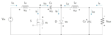
도 6은 본 발명에 따른 척컨버터 토폴로지를 나타낸 회로도이다.6 is a circuit diagram showing a topology of a chuck converter according to the present invention.
Cuk 컨버터는 미국 캘리포니아 폴리테크닉 대학의 Slobodan Cuk이 제안하였다. The Cuk converter was proposed by Slobodan Cuk of the Polytechnic University of California, USA.
Slobodan Cuk은 Boost 변환기와 Buck 변환기의 기본 회로 구조 및 작동원리를 연구 및 분석하고 각자의 특성을 살려 Cuk 컨버터를 제안하였다. Slobodan Cuk studied and analyzed the basic circuit structure and operating principle of the Boost converter and Buck converter, and proposed the Cuk converter by utilizing their respective characteristics.
벅-부스트컨버터와 비교했을 때, 회로의 전기적 동작과정은 변함이 없지만 출력단의 극성이 변화된다.Compared with the buck-boost converter, the electrical operation of the circuit is unchanged, but the polarity of the output stage is changed.
Cuk 컨버터의 정상동작 과정에서는 스위칭소자(S)가 턴 온(Turn-On) 시에, 다이오드(D)는 턴 오프(Turn-Off)되어 ![]()
![]()
![]()
![]()
![]()
![]()
![]()
![]()
스위칭소자(S)가 턴 오프(Turn-Off)되고 다이오드(D)가 턴 온 되면 ![]()
![]()
![]()
![]()
![]()
![]()
도 7은 강압모드의 척컨버터를 나타낸 회로도이며, 도 8은 승압모드의 척컨버터를 나타낸 회로도이다.7 is a circuit diagram showing a chuck converter in a step-down mode, and FIG. 8 is a circuit diagram showing a chuck converter in a boost mode.
만약, 커패시터(C1)의 크기가 충분히 커서 커패시터의 전압 Vc1의 전압이 일정하다고 가정하면, 스위칭소자(S)가 도통할 때, A, B 두 점의 전압은 각각 수식(4), 수식(5)와 같다.Assuming that the size of the capacitor C1 is sufficiently large and the voltage of the capacitor voltage Vc1 is constant, when the switching element S is conducting, the voltages at the two points A and B are Equations (4) and (5), respectively. ) Is the same.
VA1 = 0 수식(4)V A1 = 0 Equation (4)
VB1 = 0 수식(5)V B1 = 0 Equation (5)
스위칭소자(S)가 턴 오프되면 A와 B 두 점 사이의 전압은 수식(6), 수식(7)과 같다.When the switching element S is turned off, the voltage between the two points A and B is the same as in Equations (6) and (7).
VB1 = VC1 수식(6)V B1 = V C1 Equation (6)
VB2 = 0 수식(7)V B2 = 0 Equation (7)
만약, 스위칭소자(S)의 스위칭 주기가 T이고 도통 시간이 ![]()
![]()
![]()
![]()
![]()
![]()
![]()
![]()
인덕턴스(L1)과 인덕턴스(L2)의 전압은 한 사이클의 스위칭 주기 내에서 평균치가 영이므로 수식(10), 수식(11)과 같다.The voltages of inductance (L1) and inductance (L2) are equal to Equations (10) and (11) because the average value is zero within the switching period of one cycle.
![]()
![]()
![]()
![]()
따라서, Cuk 회로의 출력전압과 입력전압의 관계는 수식(12)와 같다.Therefore, the relationship between the output voltage and the input voltage of the Cuk circuit is as shown in Equation (12).
![]()
![]()
여기서, ![]()
![]()
α=0.5 일 때, ![]()
![]()
![]()
![]()
![]()
![]()
배터리 셀 밸런싱 토폴로지로 활용되는 척 컨버터는 승압모드에서 스위치(S)가 턴 온 동안, 인덕터에 에너지가 축적되고, 이때, 인덕터 전압은 배터리 전압과 같다. In the chuck converter used as a battery cell balancing topology, energy is accumulated in the inductor while the switch S is turned on in the boost mode, and at this time, the inductor voltage is the same as the battery voltage.
방전모드로 동작하는 경우는 최대부하가 걸리는 상태에서 추가로 과부하가 걸리는 경우와 경부하가 걸려있는 상태에서 과도한 부하의 증가가 있는 경우이다.When operating in the discharge mode, there is an additional overload when the maximum load is applied, and when there is an excessive increase in the load when a light load is applied.
이러한 때에는 양방향 컨버터는 필요한 에너지를 공급시키기 위해 부스트 컨버터가 된다. In this case, the bidirectional converter becomes a boost converter to supply the necessary energy.
충전모드는 과부하가 걸리지 않는 대부분의 동작 시에는 축전지의 SoC를 항상 0.97 이상으로 유지하기 위해 발생된 전원에너지로부터 충전하며 양방향 컨버터는 벅 컨버터가 되어 충전모드로 동작하게 된다.The charging mode is charged from the power energy generated to keep the SoC of the storage battery above 0.97 at all times during most operations without overload, and the bidirectional converter becomes a buck converter and operates in the charging mode.
도 9는 척컨버터의 동작모드제어 블록다이어그램을 나타낸 도면이다.9 is a diagram showing an operation mode control block diagram of the chuck converter.
입출력 전압과 전류검출을 통해 제어레퍼런스와 비교하여 전압과 전류를 제어하여 셀 밸런싱을 확보한다.Cell balancing is secured by controlling voltage and current by comparing it with a control reference through input/output voltage and current detection.
도 10은 배터리 셀밸런싱을 포함한 배터리보호회로의 블록 다이어그램이다. 10 is a block diagram of a battery protection circuit including battery cell balancing.
본 발명에 따른 척컨버터 토폴로지를 이용한 리튬이온 전지 셀밸런싱 장치는 입력 전압과 배터리 전압, 충·방전 되는 전류에 따라 제어를 수행하는 디지털테어블록과 스위칭소자의 게이트드라이버 블록과 보호회로인 열 셧다운 블록, 과부하/단락회로 검출 블록과 배터리상태 검출에 따른 신호처리 블록이 있다. The lithium-ion battery cell balancing device using the chuck converter topology according to the present invention includes a digital tare block that performs control according to an input voltage, a battery voltage, and a charging/discharging current, a gate driver block of a switching device, and a thermal shutdown block as a protection circuit. , Overload/short circuit detection block and signal processing block according to battery condition detection.
또한, 각각의 배터리 셀의 전압을 검출하고 신호변환하여 통신모듈을 통해 데이터전송과 백업정보를 확보할 수 있는 장치이다. In addition, it is a device capable of securing data transmission and backup information through a communication module by detecting the voltage of each battery cell and converting the signal.
즉, 척컨버터 토폴로지를 이용한 리튬이온 전지 셀밸런싱 장치는,That is, the lithium ion battery cell balancing device using the chuck converter topology,
각 배터리 셀(S1 ~ Sn)들의 전압, 전류, 온도를 검출하며, 각 배터리 셀의 충전 전압과 오프셋 값을 기준전압 범위로 변환하여 ADC신호필터부로 제공하기 위한 배터리변수검출부(100)와,A battery
상기 배터리변수검출부에 의해 제공된 신호를 디지털 신호로 필터링하기 위한 제1ADC신호필터부(200)와,A first ADC
각 배터리 셀의 디지털 신호를 획득하여 어느 한 배터리 셀의 디지털 신호가 다른 배터리 셀들의 디지털 신호보다 높을 경우에 다른 배터리 셀들과 밸런싱을 유지하기 위하여 해당 배터리 셀에 대응하는 스위치에 충전을 줄이기 위한 셀 밸런싱 제어 신호를 척컨버터(400)로 제공하기 위한 배터리셀밸런싱제어부(300)와,Cell balancing to reduce charging of the switch corresponding to the battery cell to maintain the balance with other battery cells when the digital signal of one battery cell is higher than the digital signal of other battery cells by acquiring the digital signal of each battery cell A battery cell balancing
상기 배터리셀밸런싱제어부로부터 제공된 셀 밸런싱 제어 신호에 따라 셀선택스위치부에 어느 한 배터리 셀에 대응하는 스위치에 충전을 줄이기 위한 동작 신호를 제공하기 위한 척컨버터(400)와,A
상기 척컨버터(400)로부터 어느 한 배터리 셀에 대응하는 스위치에 충전을 줄이기 위한 동작 신호를 획득하면, 해당 배터리 셀과 연결되어 있는 스위치에 동작 신호를 제공하여 충전되는 전류를 줄이도록 하기 위한 셀선택스위치(500)와,When an operation signal for reducing charging is obtained in a switch corresponding to a battery cell from the
각 배터리 셀들의 과부하 혹은 과방전을 검출하기 위한 과부하/과방전검출부(700)와,An overload/
상기 검출된 과부하 혹은 과방전 신호를 디지털 신호로 필터링하기 위한 제2ADC신호필터부(800)를 포함하여 구성되게 된다.It is configured to include a second ADC
구체적으로 설명하면, 상기 배터리변수검출부(100)는 각 배터리 셀(S1 ~ Sn)들의 전압, 전류, 온도를 검출하며, 각 배터리 셀의 충전 전압과 오프셋 값을 기준전압 범위로 변환하여 ADC신호필터부로 제공하게 된다.Specifically, the battery
배터리변수검출부(100)에서는 OPAMP 회로를 사용하여 각 셀의 충전 전압과 오프셋 값을 기준전압 범위로 변환하여 ADC신호필터부로 전달해 준다.The battery
셀선택스위치(500)에 고안된 셀 전압 밸런싱회로의 블록 다이어그램에서는 멀티 셀로 구성된 배터리팩은 각 셀 간에 전압을 상태에 따라 최적값을 유지시켜 주는 것이 기술이 핵심이다. In the block diagram of the cell voltage balancing circuit devised in the
셀에 같은 전류로 충전 또는 방전이 되다가 어느 한 셀의 전압이 높게 되면 해당 셀에 대응하는 스위치를 경유하여 충전되는 전류를 줄여서 다른 셀들과 밸런싱을 유지하게 된다. When a cell is charged or discharged with the same current and the voltage of one cell is high, the current charged through a switch corresponding to the cell is reduced to maintain balance with other cells.
이때, 상기 제1ADC신호필터부(200)는 상기 배터리변수검출부에 의해 제공된 신호를 디지털 신호로 필터링하게 된다.At this time, the first
그리고, 상기 배터리셀밸런싱제어부(300)는 각 배터리 셀의 디지털 신호를 획득하여 어느 한 배터리 셀의 디지털 신호가 다른 배터리 셀들의 디지털 신호보다 높을 경우에 다른 배터리 셀들과 밸런싱을 유지하기 위하여 해당 배터리 셀에 대응하는 스위치에 충전을 줄이기 위한 셀 밸런싱 제어 신호를 척컨버터(400)로 제공하기 위한 기능을 수행하게 된다.In addition, the battery cell balancing
예를 들어, 배터리셀밸런싱제어부(300)는 룩업테이블과 통신모듈 및 상태감시모듈을 포함하는 배터리셀밸런싱제어기와,For example, the battery
충방전모드, 슬립모드, 정지모드의 레퍼런스 기준모드 정보를 참조하여 배터리 셀의 제어 여부를 판단하기 위한 레퍼런스기준모드제어기를 포함하여 구성하게 된다.The configuration includes a reference reference mode controller for determining whether to control the battery cell by referring to reference reference mode information of the charge/discharge mode, the sleep mode, and the stop mode.
스위치의 온-오프의 여부는 셀전압의 상태감시값과 룩업테이블에 의한 값 간에 조건 일치를 통해 셀 밸런싱을 조절한다.Whether the switch is turned on or off is adjusted for cell balancing through condition matching between the state monitoring value of the cell voltage and the value of the lookup table.
그리고, 레퍼런스기준모드제어기를 통해 현재 배터리 셀이 충방전모드, 슬립모드, 정지모드 중 어느 모드인지를 판단하게 되며, 판단 결과에 따라 배터리 셀의 제어 여부를 결정하게 된다.In addition, it is determined whether the current battery cell is in a charging/discharging mode, a sleep mode, or a stop mode through the reference reference mode controller, and whether to control the battery cell is determined according to the determination result.
만약, 정지모드일 경우에는 배터리 셀의 제어를 수행하지 않게 되며, 슬립모드일 경우에는 슬립모드 지속시간을 산출하고, 슬립모드가 종료되면 배터리 셀을 제어할 수도 있다.In the case of the stop mode, control of the battery cell is not performed, in the case of the sleep mode, the duration of the sleep mode is calculated, and when the sleep mode is terminated, the battery cell may be controlled.
그리고, 배터리변수검출부에 의해 배터리 셀의 전압을 검출하고, 제1ADC신호필터부(200)에 의해 신호 변환하여 제공된 신호들은 통신모듈을 통해 데이터전송과 백업정보를 확보할 수 있게 된다.In addition, the voltage of the battery cell is detected by the battery variable detection unit, and the signals provided by signal conversion by the first ADC
구체적으로, 배터리셀밸런싱제어부(300)는 셀 전압 안정화를 위한 제어 신호를 생성하며 통신모듈의 통신 프로토콜을 통해 원격 검침 정보를 백업하는 기능을 가지고 있다.Specifically, the battery cell balancing
그리고, 배터리셀밸런싱제어부(300)는 각 셀의 전압 균일화 작동을 위하여 8개의 셀 중 최대 전압과 최소 전압의 차이가 SOC ±5% 이상이 되면 작동을 시작하게 된다. In addition, the battery cell balancing
이때, 상기 척컨버터(400)는 상기 배터리셀밸런싱제어부로부터 제공된 셀 밸런싱 제어 신호에 따라 셀선택스위치부에 어느 한 배터리 셀에 대응하는 스위치에 충전을 줄이기 위한 동작 신호를 제공하게 된다.At this time, the
즉, 배터리셀밸런싱제어부로부터 제공된 셀 밸런싱 제어 신호를 획득할 경우에 셀선택스위치부에 어느 한 배터리 셀에 대응하는 스위치에 충전을 줄이기 위한 동작 신호를 발생시키기 위한 컨버터드라이버(600)를 통해 발생된 동작 신호를 척컨버터로 제공하게 된다.That is, when acquiring the cell balancing control signal provided from the battery cell balancing control unit, the cell selection switch unit is generated through the
예를 들어, 배터리 셀(S1)과 연결된 스위치에 충전을 줄이기 위한 동작 신호를 제공하게 되는 것이다.For example, an operation signal for reducing charging is provided to a switch connected to the battery cell S1.
따라서, 상기 셀선택스위치(500)는 상기 척컨버터(400)로부터 어느 한 배터리 셀에 대응하는 스위치에 충전을 줄이기 위한 동작 신호를 획득하면, 해당 배터리 셀과 연결되어 있는 스위치에 동작 신호를 제공하여 충전되는 전류를 줄이도록 하는 기능을 수행하게 된다.Accordingly, when the
그리고, 상기 과부하/과방전검출부(700)는 각 배터리 셀들의 과부하 혹은 과방전을 검출하게 되며, 검출된 과부하 혹은 과방전 신호를 제2ADC신호필터부로 제공하게 되며, 상기 제2ADC신호필터부(800)는 상기 검출된 과부하 혹은 과방전 신호를 디지털 신호로 필터링하여 배터리셀밸런싱제어부(300)로 제공하게 되는 것이다.Further, the overload/
만약, 과부하 혹은 과방전 신호를 획득하게 되면 배터리셀밸런싱제어부(300)에서는 이에 따른 동작 신호를 척컨버터로 제공하게 되는 것이다.If an overload or over-discharge signal is acquired, the battery cell balancing
도 11은 본 발명에 따른 배터리 셀밸런싱 제어흐름도이다.11 is a flow chart for controlling battery cell balancing according to the present invention.
즉, 배터리의 전압, 전류, 온도를 검출하고, 배터리 셀들의 전압값과 전류값을 기준값과 비교하여 셀 밸런싱이 필요할 경우에 최적의 셀 충전조건으로 설정하고, DC-DC 컨버터를 사용하여 60초가 경과할 경우에 DC-DC 컨버터를 사용을 정지시키게 된다.In other words, it detects the voltage, current, and temperature of the battery, compares the voltage and current values of the battery cells with a reference value, sets the optimal cell charging condition when cell balancing is required, and uses a DC-DC converter to save 60 seconds. In the event of elapse, the DC-DC converter will be stopped.
결국, 본 발명의 장치는 배터리 모니터링 장치와 병렬로 사용해 배터리 팩의 성능을 향상을 도모하고 배터리 팩을 구성하는 셀 간에 용량의 편차가 있는 경우, 셀의 충전 상태(State of Charge, SoC)를 균일화하기 위해 인접한 셀과 셀 사이에서 전류를 교환하는 액티브 방식의 배터리 셀 밸런싱 기능을 제공하게 된다.Consequently, the device of the present invention is used in parallel with the battery monitoring device to improve the performance of the battery pack, and when there is a difference in capacity between cells constituting the battery pack, the state of charge (SoC) of the cell is uniform. To do this, it provides an active battery cell balancing function that exchanges current between adjacent cells and cells.
본 발명을 통해, 승강압제어가 가능하고 연속적인 에너지의 흐름을 보장하는 비절연 컨버터방식의 척컨버터(Cuk Converter)를 이용하여 배터리 보호시스템의 안정화와 전체시스템의 신뢰성을 확보하게 된다.Through the present invention, the battery protection system is stabilized and the reliability of the entire system is secured by using a non-isolated converter type Cuk converter that enables step-up and voltage control and ensures continuous flow of energy.
상기와 같은 내용의 본 발명이 속하는 기술분야의 당업자는 본 발명의 기술적 사상이나 필수적 특징을 변경하지 않고서 다른 구체적인 형태로 실시될 수 있다는 것을 이해할 수 있을 것이다. 그러므로 이상에서 기술한 실시 예들은 모든 면에서 예시된 것이며 한정적인 것이 아닌 것으로서 이해해야만 한다. Those skilled in the art to which the present invention with the above contents pertains will be able to understand that the present invention can be implemented in other specific forms without changing the technical spirit or essential features of the present invention. Therefore, the embodiments described above are exemplified in all respects and should be understood as non-limiting.
100 : 배터리변수검출부
200 : 제1ADC신호필터부
300 : 배터리셀밸런싱제어부
400 : 척컨버터
500 : 셀선택스위치
600 : 컨버터드라이버
700 : 과부하/과방전검출부
800 : 제2ADC신호필터부100: battery variable detection unit
200: first ADC signal filter unit
300: battery cell balancing control unit
400: chuck converter
500: cell selection switch
600: converter driver
700: Overload/overdischarge detection unit
800: second ADC signal filter unit
Claims (8)
각 배터리 셀(S1 ~ Sn)들의 전압, 전류, 온도를 검출하며, 각 배터리 셀의 충전 전압과 오프셋 값을 기준전압 범위로 변환하여 ADC신호필터부로 제공하기 위한 배터리변수검출부(100)와,
상기 배터리변수검출부에 의해 제공된 신호를 디지털 신호로 필터링하기 위한 제1ADC신호필터부(200)와,
각 배터리 셀의 디지털 신호를 획득하여 어느 한 배터리 셀의 디지털 신호가 다른 배터리 셀들의 디지털 신호보다 높을 경우에 다른 배터리 셀들과 밸런싱을 유지하기 위하여 해당 배터리 셀에 대응하는 스위치에 충전을 줄이기 위한 셀 밸런싱 제어 신호를 척컨버터(400)로 제공하기 위한 배터리셀밸런싱제어부(300)와,
상기 배터리셀밸런싱제어부로부터 제공된 셀 밸런싱 제어 신호에 따라 셀선택스위치부에 어느 한 배터리 셀에 대응하는 스위치에 충전을 줄이기 위한 동작 신호를 제공하기 위한 척컨버터(400)와,
상기 척컨버터(400)로부터 어느 한 배터리 셀에 대응하는 스위치에 충전을 줄이기 위한 동작 신호를 획득하면, 해당 배터리 셀과 연결되어 있는 스위치에 동작 신호를 제공하여 충전되는 전류를 줄이도록 하여 셀 밸런싱을 제공하기 위한 셀선택스위치(500)를 포함하여 구성되되,
상기 척컨버터(400)는,
인덕턴스(L1);와
인덕턴스와 직렬로 연결되는 커패시터(C1);와
상기 커패시터와 직렬로 연결되는 인덕턴스(L2);와
상기 인덕턴스(L1)와 커패시터(C1) 사이에 병렬로 연결되는 스위칭소자(S);와
상기 커패시터(C1)와 인덕턴스(L2) 사이에 병렬로 연결되는 다이오드(D);와
상기 인덕턴스(L2)의 끝단에 병렬로 연결되는 커패시터(C2);를 포함하여 구성됨으로써,
상기 스위칭소자(S)가 턴 온(Turn-On) 시에, 다이오드(D)는 턴 오프(Turn-Off)되어
상기 스위칭소자(S)가 턴 오프(Turn-Off)되고, 다이오드(D)가 턴 온 되면
In the lithium ion battery cell balancing device using a chuck converter topology,
A battery variable detection unit 100 for detecting voltage, current, and temperature of each battery cell (S1 ~ Sn), converting the charging voltage and offset value of each battery cell into a reference voltage range and providing it to the ADC signal filter unit,
A first ADC signal filter unit 200 for filtering a signal provided by the battery variable detection unit into a digital signal,
Cell balancing to reduce charging of the switch corresponding to the battery cell to maintain the balance with other battery cells when the digital signal of one battery cell is higher than the digital signal of other battery cells by acquiring the digital signal of each battery cell A battery cell balancing control unit 300 for providing a control signal to the chuck converter 400,
A chuck converter 400 for providing an operation signal for reducing charging to a switch corresponding to a battery cell in the cell selection switch unit according to a cell balancing control signal provided from the battery cell balancing control unit,
When an operation signal for reducing charging is obtained from a switch corresponding to a battery cell from the chuck converter 400, an operation signal is provided to a switch connected to the battery cell to reduce the charged current, thereby performing cell balancing. It is configured to include a cell selection switch 500 for providing,
The chuck converter 400,
Inductance (L1); and
A capacitor C1 connected in series with the inductance; and
Inductance L2 connected in series with the capacitor; And
A switching device (S) connected in parallel between the inductance (L1) and the capacitor (C1); And
A diode D connected in parallel between the capacitor C1 and the inductance L2; and
By including a capacitor (C2) connected in parallel to the end of the inductance (L2),
When the switching device (S) is turned on (Turn-On), the diode (D) is turned off (Turn-Off)
When the switching element (S) is turned off (Turn-Off) and the diode (D) is turned on
각 배터리 셀(S1 ~ Sn)들의 전압, 전류, 온도를 검출하며, 각 배터리 셀의 충전 전압과 오프셋 값을 기준전압 범위로 변환하여 ADC신호필터부로 제공하기 위한 배터리변수검출부(100)와,
상기 배터리변수검출부에 의해 제공된 신호를 디지털 신호로 필터링하기 위한 제1ADC신호필터부(200)와,
각 배터리 셀의 디지털 신호를 획득하여 어느 한 배터리 셀의 디지털 신호가 다른 배터리 셀들의 디지털 신호보다 높을 경우에 다른 배터리 셀들과 밸런싱을 유지하기 위하여 해당 배터리 셀에 대응하는 스위치에 충전을 줄이기 위한 셀 밸런싱 제어 신호를 척컨버터(400)로 제공하기 위한 배터리셀밸런싱제어부(300)와,
상기 배터리셀밸런싱제어부로부터 제공된 셀 밸런싱 제어 신호에 따라 셀선택스위치부에 어느 한 배터리 셀에 대응하는 스위치에 충전을 줄이기 위한 동작 신호를 제공하기 위한 척컨버터(400)와,
상기 척컨버터(400)로부터 어느 한 배터리 셀에 대응하는 스위치에 충전을 줄이기 위한 동작 신호를 획득하면, 해당 배터리 셀과 연결되어 있는 스위치에 동작 신호를 제공하여 충전되는 전류를 줄이도록 하기 위한 셀선택스위치(500)와,
각 배터리 셀들의 과부하 혹은 과방전을 검출하기 위한 과부하/과방전검출부(700)와,
상기 검출된 과부하 혹은 과방전 신호를 디지털 신호로 필터링하기 위한 제2ADC신호필터부(800)를 포함하여 구성되되,
상기 척컨버터(400)는,
인덕턴스(L1);와
인덕턴스와 직렬로 연결되는 커패시터(C1);와
상기 커패시터와 직렬로 연결되는 인덕턴스(L2);와
상기 인덕턴스(L1)와 커패시터(C1) 사이에 병렬로 연결되는 스위칭소자(S);와
상기 커패시터(C1)와 인덕턴스(L2) 사이에 병렬로 연결되는 다이오드(D);와
상기 인덕턴스(L2)의 끝단에 병렬로 연결되는 커패시터(C2);를 포함하여 구성됨으로써,
상기 스위칭소자(S)가 턴 온(Turn-On) 시에, 다이오드(D)는 턴 오프(Turn-Off)되어
상기 스위칭소자(S)가 턴 오프(Turn-Off)되고, 다이오드(D)가 턴 온 되면
In the lithium ion battery cell balancing device using a chuck converter topology,
A battery variable detection unit 100 for detecting voltage, current, and temperature of each battery cell (S1 ~ Sn), converting the charging voltage and offset value of each battery cell into a reference voltage range and providing it to the ADC signal filter unit,
A first ADC signal filter unit 200 for filtering a signal provided by the battery variable detection unit into a digital signal,
Cell balancing to reduce charging of the switch corresponding to the battery cell to maintain the balance with other battery cells when the digital signal of one battery cell is higher than the digital signal of other battery cells by acquiring the digital signal of each battery cell A battery cell balancing control unit 300 for providing a control signal to the chuck converter 400,
A chuck converter 400 for providing an operation signal for reducing charging to a switch corresponding to a battery cell in the cell selection switch unit according to a cell balancing control signal provided from the battery cell balancing control unit,
When an operation signal for reducing charging is obtained in a switch corresponding to a battery cell from the chuck converter 400, a cell selection for reducing the charged current by providing an operation signal to a switch connected to the corresponding battery cell With the switch 500,
An overload/overdischarge detection unit 700 for detecting overload or overdischarge of each battery cell,
It is configured to include a second ADC signal filter unit 800 for filtering the detected overload or over-discharge signal into a digital signal,
The chuck converter 400,
Inductance (L1); and
A capacitor C1 connected in series with the inductance; and
Inductance L2 connected in series with the capacitor; And
A switching device (S) connected in parallel between the inductance (L1) and the capacitor (C1); And
A diode D connected in parallel between the capacitor C1 and the inductance L2; and
By including a capacitor (C2) connected in parallel to the end of the inductance (L2),
When the switching device (S) is turned on (Turn-On), the diode (D) is turned off (Turn-Off)
When the switching device (S) is turned off (Turn-Off) and the diode (D) is turned on
상기 척컨버터(400)는,
강압형 컨버터와 승압형 컨버터를 탠덤에 합체한 구성으로 입력과 출력에 콘덴서로 결합되는 것을 특징으로 하는 척컨버터 토폴로지를 이용한 리튬이온 전지 셀밸런싱 장치.
The method according to claim 1 or 2,
The chuck converter 400,
A lithium ion battery cell balancing device using a chuck converter topology, characterized in that a step-down converter and a step-up converter are combined in a tandem and are coupled to input and output as a capacitor.
상기 척컨버터(400)는,
α=0.5 일 때,
The method according to claim 1 or 2,
The chuck converter 400,
When α=0.5,
상기 리튬이온 전지 셀밸런싱 장치는,
에너지의 흐름이 연속성을 갖는 것을 특징으로 하는 척컨버터 토폴로지를 이용한 리튬이온 전지 셀밸런싱 장치.
The method according to claim 1 or 2,
The lithium ion battery cell balancing device,
Lithium ion battery cell balancing device using a chuck converter topology, characterized in that the flow of energy has continuity.
상기 리튬이온 전지 셀밸런싱 장치는,
셀 밸런싱을 위한 전압, 전류검출 메카니즘을 통한 배터리 셀 안정화을 제공하는 것을 특징으로 하는 척컨버터 토폴로지를 이용한 리튬이온 전지 셀밸런싱 장치.
The method according to claim 1 or 2,
The lithium ion battery cell balancing device,
A lithium ion battery cell balancing device using a chuck converter topology, characterized in that it provides battery cell stabilization through a voltage and current detection mechanism for cell balancing.
Priority Applications (1)
| Application Number | Priority Date | Filing Date | Title |
|---|---|---|---|
| KR1020190022495A KR102151652B1 (en) | 2019-02-26 | 2019-02-26 | Using Cuk Converter topology Li-ion battery cell balancing strategy |
Applications Claiming Priority (1)
| Application Number | Priority Date | Filing Date | Title |
|---|---|---|---|
| KR1020190022495A KR102151652B1 (en) | 2019-02-26 | 2019-02-26 | Using Cuk Converter topology Li-ion battery cell balancing strategy |
Publications (1)
| Publication Number | Publication Date |
|---|---|
| KR102151652B1 true KR102151652B1 (en) | 2020-09-03 |
Family
ID=72469489
Family Applications (1)
| Application Number | Title | Priority Date | Filing Date |
|---|---|---|---|
| KR1020190022495A Active KR102151652B1 (en) | 2019-02-26 | 2019-02-26 | Using Cuk Converter topology Li-ion battery cell balancing strategy |
Country Status (1)
| Country | Link |
|---|---|
| KR (1) | KR102151652B1 (en) |
Cited By (9)
| Publication number | Priority date | Publication date | Assignee | Title |
|---|---|---|---|---|
| CN114123376A (en) * | 2021-10-13 | 2022-03-01 | 国网江苏省电力有限公司东台市供电分公司 | Current interrupted soft switch implementation method based on switched inductor battery equalizer |
| CN114824584A (en) * | 2022-06-14 | 2022-07-29 | 扬州贝尔斯通科技有限公司 | Battery thermal management method suitable for distributed energy storage system |
| CN115333158A (en) * | 2022-08-31 | 2022-11-11 | 燕山大学 | Grid-connected inverter |
| CN115441542A (en) * | 2022-09-16 | 2022-12-06 | 清华大学 | Lithium battery system with variable structure and control strategy thereof |
| CN115514041A (en) * | 2022-09-14 | 2022-12-23 | 中国空间技术研究院 | A non-dissipative equalization management system for space lithium-ion batteries |
| CN117856401A (en) * | 2024-01-09 | 2024-04-09 | 中南大学 | A battery balancing control system based on wireless power feedback and a control method thereof |
| CN119834400A (en) * | 2024-12-02 | 2025-04-15 | 三峡大学 | Zeta converter-based active equalization circuit for series battery pack |
| CN120810694A (en) * | 2025-09-04 | 2025-10-17 | 四川大学 | DC power stabilizing device of MMC bridge arm cascade dual-port switching type energy storage module |
| CN121546920A (en) * | 2026-01-20 | 2026-02-17 | 华侨大学 | A DC-DC forward buck-boost power conversion circuit based on cascaded Cuk topology |
Citations (5)
| Publication number | Priority date | Publication date | Assignee | Title |
|---|---|---|---|---|
| JP3120674U (en) * | 2005-11-09 | 2006-04-20 | 華美電子股▼分▲有限公司 | Intelligent equal charger |
| US20060132102A1 (en) * | 2004-11-10 | 2006-06-22 | Harvey Troy A | Maximum power point tracking charge controller for double layer capacitors |
| KR101165593B1 (en) | 2012-02-07 | 2012-07-23 | (주)이미지스테크놀로지 | A cell balancing circuit device of battery management system using bidirectional dc-dc converter |
| JP2013085468A (en) * | 2007-09-28 | 2013-05-09 | Hitachi Ltd | Battery system and integrated circuit for battery cell control |
| KR20150115281A (en) * | 2014-04-03 | 2015-10-14 | 주식회사 아모센스 | Apparatus and Method for Balancing Charging Cells |
-
2019
- 2019-02-26 KR KR1020190022495A patent/KR102151652B1/en active Active
Patent Citations (6)
| Publication number | Priority date | Publication date | Assignee | Title |
|---|---|---|---|---|
| US20060132102A1 (en) * | 2004-11-10 | 2006-06-22 | Harvey Troy A | Maximum power point tracking charge controller for double layer capacitors |
| JP3120674U (en) * | 2005-11-09 | 2006-04-20 | 華美電子股▼分▲有限公司 | Intelligent equal charger |
| US20070145946A1 (en) * | 2005-11-09 | 2007-06-28 | Sino- American Electronic Co., Ltd. | Intelligent equalizing battery charger having equalization charging circuitry |
| JP2013085468A (en) * | 2007-09-28 | 2013-05-09 | Hitachi Ltd | Battery system and integrated circuit for battery cell control |
| KR101165593B1 (en) | 2012-02-07 | 2012-07-23 | (주)이미지스테크놀로지 | A cell balancing circuit device of battery management system using bidirectional dc-dc converter |
| KR20150115281A (en) * | 2014-04-03 | 2015-10-14 | 주식회사 아모센스 | Apparatus and Method for Balancing Charging Cells |
Cited By (9)
| Publication number | Priority date | Publication date | Assignee | Title |
|---|---|---|---|---|
| CN114123376A (en) * | 2021-10-13 | 2022-03-01 | 国网江苏省电力有限公司东台市供电分公司 | Current interrupted soft switch implementation method based on switched inductor battery equalizer |
| CN114824584A (en) * | 2022-06-14 | 2022-07-29 | 扬州贝尔斯通科技有限公司 | Battery thermal management method suitable for distributed energy storage system |
| CN115333158A (en) * | 2022-08-31 | 2022-11-11 | 燕山大学 | Grid-connected inverter |
| CN115514041A (en) * | 2022-09-14 | 2022-12-23 | 中国空间技术研究院 | A non-dissipative equalization management system for space lithium-ion batteries |
| CN115441542A (en) * | 2022-09-16 | 2022-12-06 | 清华大学 | Lithium battery system with variable structure and control strategy thereof |
| CN117856401A (en) * | 2024-01-09 | 2024-04-09 | 中南大学 | A battery balancing control system based on wireless power feedback and a control method thereof |
| CN119834400A (en) * | 2024-12-02 | 2025-04-15 | 三峡大学 | Zeta converter-based active equalization circuit for series battery pack |
| CN120810694A (en) * | 2025-09-04 | 2025-10-17 | 四川大学 | DC power stabilizing device of MMC bridge arm cascade dual-port switching type energy storage module |
| CN121546920A (en) * | 2026-01-20 | 2026-02-17 | 华侨大学 | A DC-DC forward buck-boost power conversion circuit based on cascaded Cuk topology |
Similar Documents
| Publication | Publication Date | Title |
|---|---|---|
| KR102151652B1 (en) | Using Cuk Converter topology Li-ion battery cell balancing strategy | |
| US12142721B2 (en) | Methods for battery charging and formation | |
| KR101631065B1 (en) | Battery system and method for connecting battery | |
| US10347952B2 (en) | Battery system | |
| US9231407B2 (en) | Battery system, method of controlling the same, and energy storage system including the battery system | |
| US20150194707A1 (en) | Battery pack, energy storage system including the battery pack, and method of operating the battery pack | |
| US9401616B2 (en) | Battery pack, energy storage system including battery pack, and method of charging battery pack | |
| US9118191B2 (en) | Cell balancing method, cell balancing device, and energy storage system including the cell balancing device | |
| KR102283790B1 (en) | Battery rack and driving method thereof | |
| US9300016B2 (en) | Battery system and energy storage system | |
| US9071056B2 (en) | Apparatus and method for managing battery cell, and energy storage system | |
| US9172259B2 (en) | Apparatus for managing battery, and energy storage system | |
| US9231440B2 (en) | Power supply apparatus and controlling method of the same | |
| US9088164B2 (en) | Battery system, controlling method of the same, and power storage system including the battery pack | |
| US11158888B2 (en) | Management device and power storage system | |
| US20130187465A1 (en) | Power management system | |
| KR20130112739A (en) | Battery pack, method of measuring voltage of the battery pack, and energy storage system including the battery pack | |
| KR20130142409A (en) | Battery pack and its control method | |
| JP4165798B2 (en) | Power supply | |
| CN112913107A (en) | Power storage system and charge control method | |
| JP2024132995A (en) | Battery Systems |
Legal Events
| Date | Code | Title | Description |
|---|---|---|---|
| PA0109 | Patent application |
St.27 status event code: A-0-1-A10-A12-nap-PA0109 |
|
| PA0201 | Request for examination |
St.27 status event code: A-1-2-D10-D11-exm-PA0201 |
|
| D13-X000 | Search requested |
St.27 status event code: A-1-2-D10-D13-srh-X000 |
|
| D14-X000 | Search report completed |
St.27 status event code: A-1-2-D10-D14-srh-X000 |
|
| PE0902 | Notice of grounds for rejection |
St.27 status event code: A-1-2-D10-D21-exm-PE0902 |
|
| E13-X000 | Pre-grant limitation requested |
St.27 status event code: A-2-3-E10-E13-lim-X000 |
|
| P11-X000 | Amendment of application requested |
St.27 status event code: A-2-2-P10-P11-nap-X000 |
|
| P13-X000 | Application amended |
St.27 status event code: A-2-2-P10-P13-nap-X000 |
|
| E701 | Decision to grant or registration of patent right | ||
| PE0701 | Decision of registration |
St.27 status event code: A-1-2-D10-D22-exm-PE0701 |
|
| GRNT | Written decision to grant | ||
| PR0701 | Registration of establishment |
St.27 status event code: A-2-4-F10-F11-exm-PR0701 |
|
| PR1002 | Payment of registration fee |
St.27 status event code: A-2-2-U10-U11-oth-PR1002 Fee payment year number: 1 |
|
| PG1601 | Publication of registration |
St.27 status event code: A-4-4-Q10-Q13-nap-PG1601 |
|
| P22-X000 | Classification modified |
St.27 status event code: A-4-4-P10-P22-nap-X000 |
|
| PR1001 | Payment of annual fee |
St.27 status event code: A-4-4-U10-U11-oth-PR1001 Fee payment year number: 4 |
|
| PR1001 | Payment of annual fee |
St.27 status event code: A-4-4-U10-U11-oth-PR1001 Fee payment year number: 5 |
|
| R18-X000 | Changes to party contact information recorded |
St.27 status event code: A-5-5-R10-R18-oth-X000 |
|
| R18-X000 | Changes to party contact information recorded |
St.27 status event code: A-5-5-R10-R18-oth-X000 |
|
| PR1001 | Payment of annual fee |
St.27 status event code: A-4-4-U10-U11-oth-PR1001 Fee payment year number: 6 |
|
| U11 | Full renewal or maintenance fee paid |
Free format text: ST27 STATUS EVENT CODE: A-4-4-U10-U11-OTH-PR1001 (AS PROVIDED BY THE NATIONAL OFFICE) Year of fee payment: 6 |
|
| P22-X000 | Classification modified |
St.27 status event code: A-4-4-P10-P22-nap-X000 |
|
| R18-X000 | Changes to party contact information recorded |
St.27 status event code: A-5-5-R10-R18-oth-X000 |