KR102134419B1 - Thermographic image sensing device - Google Patents
Thermographic image sensing device Download PDFInfo
- Publication number
- KR102134419B1 KR102134419B1 KR1020190101518A KR20190101518A KR102134419B1 KR 102134419 B1 KR102134419 B1 KR 102134419B1 KR 1020190101518 A KR1020190101518 A KR 1020190101518A KR 20190101518 A KR20190101518 A KR 20190101518A KR 102134419 B1 KR102134419 B1 KR 102134419B1
- Authority
- KR
- South Korea
- Prior art keywords
- thermal image
- unit
- information
- sensing device
- remaining area
- Prior art date
- Legal status (The legal status is an assumption and is not a legal conclusion. Google has not performed a legal analysis and makes no representation as to the accuracy of the status listed.)
- Active
Links
Images

Classifications
-
- G—PHYSICS
- G08—SIGNALLING
- G08B—SIGNALLING SYSTEMS, e.g. PERSONAL CALLING SYSTEMS; ORDER TELEGRAPHS; ALARM SYSTEMS
- G08B21/00—Alarms responsive to a single specified undesired or abnormal condition and not otherwise provided for
- G08B21/02—Alarms for ensuring the safety of persons
- G08B21/10—Alarms for ensuring the safety of persons responsive to calamitous events, e.g. tornados or earthquakes
-
- G—PHYSICS
- G01—MEASURING; TESTING
- G01J—MEASUREMENT OF INTENSITY, VELOCITY, SPECTRAL CONTENT, POLARISATION, PHASE OR PULSE CHARACTERISTICS OF INFRARED, VISIBLE OR ULTRAVIOLET LIGHT; COLORIMETRY; RADIATION PYROMETRY
- G01J5/00—Radiation pyrometry, e.g. infrared or optical thermometry
- G01J5/48—Thermography; Techniques using wholly visual means
-
- G—PHYSICS
- G06—COMPUTING OR CALCULATING; COUNTING
- G06T—IMAGE DATA PROCESSING OR GENERATION, IN GENERAL
- G06T7/00—Image analysis
- G06T7/10—Segmentation; Edge detection
- G06T7/11—Region-based segmentation
-
- G—PHYSICS
- G08—SIGNALLING
- G08B—SIGNALLING SYSTEMS, e.g. PERSONAL CALLING SYSTEMS; ORDER TELEGRAPHS; ALARM SYSTEMS
- G08B17/00—Fire alarms; Alarms responsive to explosion
- G08B17/12—Actuation by presence of radiation or particles, e.g. of infrared radiation or of ions
- G08B17/125—Actuation by presence of radiation or particles, e.g. of infrared radiation or of ions by using a video camera to detect fire or smoke
-
- G—PHYSICS
- G08—SIGNALLING
- G08B—SIGNALLING SYSTEMS, e.g. PERSONAL CALLING SYSTEMS; ORDER TELEGRAPHS; ALARM SYSTEMS
- G08B25/00—Alarm systems in which the location of the alarm condition is signalled to a central station, e.g. fire or police telegraphic systems
- G08B25/14—Central alarm receiver or annunciator arrangements
-
- G—PHYSICS
- G08—SIGNALLING
- G08B—SIGNALLING SYSTEMS, e.g. PERSONAL CALLING SYSTEMS; ORDER TELEGRAPHS; ALARM SYSTEMS
- G08B5/00—Visible signalling systems, e.g. visible personal calling systems or remote indication of seats occupied
- G08B5/22—Visible signalling systems, e.g. visible personal calling systems or remote indication of seats occupied using electric transmission; using electromagnetic transmission
- G08B5/36—Visible signalling systems, e.g. visible personal calling systems or remote indication of seats occupied using electric transmission; using electromagnetic transmission using visible light sources
-
- H—ELECTRICITY
- H04—ELECTRIC COMMUNICATION TECHNIQUE
- H04N—PICTORIAL COMMUNICATION, e.g. TELEVISION
- H04N7/00—Television systems
- H04N7/18—Closed-circuit television [CCTV] systems, i.e. systems in which the video signal is not broadcast
-
- G01J2005/0081—
Landscapes
- Physics & Mathematics (AREA)
- General Physics & Mathematics (AREA)
- Engineering & Computer Science (AREA)
- Business, Economics & Management (AREA)
- Emergency Management (AREA)
- Multimedia (AREA)
- Computer Vision & Pattern Recognition (AREA)
- Theoretical Computer Science (AREA)
- Life Sciences & Earth Sciences (AREA)
- Environmental & Geological Engineering (AREA)
- General Life Sciences & Earth Sciences (AREA)
- Geology (AREA)
- Signal Processing (AREA)
- Electromagnetism (AREA)
- Spectroscopy & Molecular Physics (AREA)
- Alarm Systems (AREA)
Abstract
Description
본 발명은 열화상 감지 디바이스에 관한 것으로, 더욱 상세하게는 관심 영역의 유무와 방향을 감지하고 그에 대응된 알람을 제공하는 열화상 감지 디바이스에 관한 것이다.The present invention relates to a thermal image sensing device, and more particularly, to a thermal image sensing device that detects the presence and direction of a region of interest and provides an alarm corresponding thereto.
산불이 발생되어 진화 작업을 수행하는 과정에서 잔불이 형성될 수 있다. 잔불은, 바람에 의해 다시 활성화될 여지가 있으므로 잔불 제거가 중요할 수 있다. 잔불 제거에 열화상 카메라가 이용될 수 있다.Wildfires can occur, and as a result, fires can form during the process of extinguishing. The remaining fire can be reactivated by the wind, so removing the remaining fire can be important. A thermal imaging camera may be used to remove the remaining light.
열화상 카메라는 열화상 이미지를 획득할 수 있으나, 작업자가 열화상 이미지로부터 잔불의 유무 및 위치를 파악하는데 오류가 발생될 수 있다. 따라서 잔불의 유무 및 위치를 열화상 이미지로부터 파악하여 알람을 제공하는 장치가 요구될 수 있다.A thermal imaging camera may acquire a thermal image, but an error may occur in an operator's grasp of the presence and location of a residual image from the thermal image. Therefore, a device for providing an alarm by grasping the presence and location of a remaining payment from a thermal image may be required.
본 발명이 이루고자 하는 기술적 과제는, 열화상 이미지로부터 잔불 영역을 추출하는 열화상 감지 디바이스를 제공하는 것이다.A technical problem to be achieved by the present invention is to provide a thermal image sensing device for extracting a residual area from a thermal image.
본 발명의 다른(another) 기술적 과제는, 잔불 영역의 유무 및 위치에 관한 정보를 추출하는 열화상 감지 디바이스를 제공하는 것이다.Another technical problem of the present invention is to provide a thermal image sensing device that extracts information regarding the presence and location of a residual area.
본 발명의 다른(another) 기술적 과제는, 잔불 영역의 위치에 대응된 이미지를 표시하는 디스플레이 유닛을 포함하는 열화상 감지 디바이스를 제공하는 것이다.Another technical problem of the present invention is to provide a thermal image sensing device including a display unit that displays an image corresponding to the location of the remaining area.
본 발명의 다른(another) 기술적 과제는, 적어도 하나의 잔불 영역에 관한 정보를 단말기를 통해 확인할 수 있는 통제 시스템을 제공하는 것이다.Another technical problem of the present invention is to provide a control system capable of confirming information on at least one remaining area through a terminal.
본 발명이 이루고자 하는 기술적 과제는 이상에서 언급한 기술적 과제로 제한되지 않으며, 언급되지 않은 또 다른 기술적 과제들은 아래의 기재로부터 본 발명이 속하는 기술 분야에서 통상의 지식을 가진 자에게 명확하게 이해될 수 있을 것이다.The technical problem to be achieved by the present invention is not limited to the technical problems mentioned above, and other technical problems not mentioned can be clearly understood by a person having ordinary knowledge in the technical field to which the present invention belongs from the following description. There will be.
본 발명의 일 측면(an aspect)에 따르면, 본 발명은, 열화상 감지 디바이스에 있어서, 바디; 상기 바디에 위치하며 주변 온도를 측정하는 온도 센서를 구비하는 센서 유닛; 상기 바디의 전면(前面)에 위치하며 열화상 이미지를 획득하는 카메라 유닛; 상기 바디에 위치하며, 상기 주변 온도를 기초로 상기 열화상 이미지를 처리하여 잔불 영역을 추출하는 제어 유닛; 상기 열화상 감지 디바이스의 위치 정보를 획득하는 GPS 모듈; 상기 열화상 감지 디바이스의 관성 정보를 획득하는 IMU; 그리고 상기 바디에 위치하고 상기 잔불 영역의 위치 정보에 대응된 알람을 제공하는 알람 어셈블리를 포함하고, 상기 제어 유닛은, 상기 열화상 감지 디바이스의 위치 정보와 관성 정보에 기초하여 상기 잔불 영역의 위치 정보를 추출하는, 열화상 감지 디바이스를 제공할 수 있다.According to an aspect of the present invention, the present invention provides a thermal image sensing device comprising: a body; A sensor unit located in the body and having a temperature sensor for measuring ambient temperature; A camera unit located on the front surface of the body and acquiring a thermal image; A control unit located in the body and processing the thermal image based on the ambient temperature to extract a residual area; A GPS module for obtaining location information of the thermal image sensing device; An IMU for obtaining inertia information of the thermal image sensing device; And an alarm assembly located in the body and providing an alarm corresponding to the location information of the residual region, and the control unit is configured to display the location information of the residual region based on the location information and the inertia information of the thermal image sensing device. It is possible to provide a thermal imaging device for extraction.
본 발명의 다른 측면(another aspect)에 따르면, 열화상 이미지를 획득하는 카메라 유닛과, 주변 온도 정보를 획득하는 센서 유닛과, 상기 주변 온도 정보에 기초하여 상기 열화상 이미지로부터 잔불 영역의 유무와 위치를 판단하는 제어 유닛과, 네트워크와 통신하는 통신 유닛을 포함하는, 적어도 하나의 열화상 감지 디바이스; 상기 적어도 하나의 열화상 감지 디바이스로부터 상기 잔불 영역에 관한 정보를 상기 네트워크를 통해 제공받아 취합하는 서버; 그리고 상기 서버로부터 상기 잔불 영역에 관한 정보를 상기 네트워크를 통해 수신하여 표시하는 단말기를 포함하고, 상기 단말기는, 단말기 본체; 상기 단말기 본체에 위치하고 상기 서버로부터 상기 잔불 영역에 관한 정보를 수신하는 통신 모듈; 상기 단말기 본체에 위치하고 이미지를 표시하는 단말기 스크린; 그리고 상기 잔불 영역에 관한 정보를 상기 단말기 스크린에 표시하는 제1 어플리케이션을 구동시키는 프로세서(processor)를 포함하고, 상기 열화상 감지 디바이스는, 상기 열화상 감지 디바이스의 위치 정보를 획득하는 GPS 모듈; 그리고 상기 열화상 감지 디바이스의 관성 정보를 획득하는 IMU를 더 포함하고, 상기 제어 유닛은, 상기 열화상 감지 디바이스의 위치 정보와 관성 정보에 기초하여 상기 잔불 영역의 위치 정보를 추출하는, 통제 시스템을 제공할 수 있다.According to another aspect of the present invention, a camera unit for obtaining a thermal image, a sensor unit for obtaining ambient temperature information, and the presence and location of a residual area from the thermal image based on the ambient temperature information At least one thermal image sensing device comprising a control unit for determining, and a communication unit for communicating with the network; A server configured to receive and collect information on the remaining area from the at least one thermal image sensing device through the network; And a terminal receiving and displaying information on the remaining area from the server through the network, the terminal comprising: a terminal body; A communication module located in the terminal body and receiving information on the remaining area from the server; A terminal screen positioned on the terminal body and displaying an image; And a processor for driving a first application that displays information on the remaining area on the terminal screen, wherein the thermal image sensing device comprises: a GPS module for obtaining location information of the thermal image sensing device; And further comprising an IMU to obtain the inertia information of the thermal image sensing device, the control unit, based on the location information and the inertia information of the thermal image sensing device extracts the location information of the residual area, the control system Can provide.
본 발명의 일 실시예에 따른 열화상 감지 디바이스는, 열화상 이미지로부터 잔불 영역을 추출할 수 있다.The thermal image sensing device according to an embodiment of the present invention may extract a residual area from a thermal image.
본 발명의 일 실시예에 따른 열화상 감지 디바이스는, 잔불 영역의 유무 및 위치에 관한 정보를 추출할 수 있다.The thermal image sensing device according to an embodiment of the present invention may extract information on the presence and location of the residual area.
본 발명의 일 실시예에 따른 열화상 감지 디바이스는, 잔불 영역의 위치에 대응된 이미지를 표시하는 디스플레이 유닛을 포함할 수 있다.The thermal image sensing device according to an embodiment of the present invention may include a display unit that displays an image corresponding to the location of the remaining area.
본 발명의 일 실시예에 따른 통제 시스템은, 적어도 하나의 잔불 영역에 관한 정보를 단말기를 통해 확인할 수 있다.The control system according to an embodiment of the present invention may check information on at least one remaining area through a terminal.
본 발명의 효과는 상기한 효과로 한정되는 것은 아니며, 본 발명의 상세한 설명 또는 특허청구범위에 기재된 발명의 구성으로부터 추론 가능한 모든 효과를 포함하는 것으로 이해되어야 한다.It should be understood that the effects of the present invention are not limited to the above-described effects, and include all effects that can be deduced from the configuration of the invention described in the detailed description or claims of the present invention.
도 1은, 본 발명의 일 실시예에 따른 열화상 감지 디바이스를 나타낸 도면이다.
도 2는, 본 발명의 일 실시예에 따른 열화상 감지 디바이스의 블록도를 나타낸 도면이다.
도 3은 도 1에 도시된 열화상 감지 디바이스를 다른 각도에서 나타낸 도면이다.
도 4는, 본 발명의 일 실시예에 따른 열화상 감지 디바이스를 측면에서 바라본 모습을 나타낸 도면이다.
도 5 및 6은, 본 발명의 일 실시예에 따른 영상 처리부가 열화상 이미지를 처리하여 관심 영역을 나타낸 도면이다.
도 7 및 8은, 잔불 영역 판단부가 관심 영역의 위치를 판단하는 방식을 예시한 도면이다.
도 9 내지 11은, 알람 형성부에 의해 알람 어셈블리가 작동되는 모습을 나타낸 도면이다.
도 12는, 본 발명의 일 실시예에 따른 통제 시스템을 나타낸 도면이다.
도 13은, 본 발명의 일 실시예에 따른 통제 시스템에서 작동되는 단말기의 모습을 나타낸 도면이다.
도 14는, 터치 입력에 대응된 작동을 수행한 단말기의 모습을 나타낸 도면이다.1 is a view showing a thermal image sensing device according to an embodiment of the present invention.
2 is a block diagram of a thermal image sensing device according to an embodiment of the present invention.
FIG. 3 is a view showing the thermal image sensing device illustrated in FIG. 1 from a different angle.
4 is a view showing a side view of the thermal image sensing device according to an embodiment of the present invention.
5 and 6 are views illustrating an area of interest by processing a thermal image by an image processing unit according to an embodiment of the present invention.
7 and 8 are diagrams illustrating a method in which the residual area determining unit determines the position of the region of interest.
9 to 11 are views showing a state in which the alarm assembly is operated by the alarm forming unit.
12 is a view showing a control system according to an embodiment of the present invention.
13 is a diagram illustrating a state of a terminal operated in a control system according to an embodiment of the present invention.
14 is a diagram illustrating a state of a terminal performing an operation corresponding to a touch input.
이하에서는 첨부한 도면을 참조하여 본 발명을 설명하기로 한다. 그러나 본 발명은 여러 가지 상이한 형태로 구현될 수 있으며, 따라서 여기에서 설명하는 실시예로 한정되는 것은 아니다. 그리고 도면에서 본 발명을 명확하게 설명하기 위해서 설명과 관계없는 부분은 생략하였으며, 명세서 전체를 통하여 유사한 부분에 대해서는 유사한 도면 부호를 붙였다.Hereinafter, the present invention will be described with reference to the accompanying drawings. However, the present invention may be implemented in various different forms, and thus is not limited to the embodiments described herein. In addition, in order to clearly describe the present invention in the drawings, parts irrelevant to the description are omitted, and like reference numerals are assigned to similar parts throughout the specification.
명세서 전체에서, 어떤 부분이 다른 부분과 "연결(접속, 접촉, 결합)"되어 있다고 할 때, 이는 "직접적으로 연결"되어 있는 경우뿐 아니라, 그 중간에 다른 부재를 사이에 두고 "간접적으로 연결"되어 있는 경우도 포함한다. 또한 어떤 부분이 어떤 구성요소를 "포함"한다고 할 때, 이는 특별히 반대되는 기재가 없는 한 다른 구성요소를 제외하는 것이 아니라 다른 구성요소를 더 구비할 수 있다는 것을 의미한다.Throughout the specification, when a part is said to be "connected (connected, contacted, coupled)" to another part, it is not only "directly connected", but also "indirectly connected" with another member in between. "It includes the case where it is. Also, when a part “includes” a certain component, this means that other components may be further provided instead of excluding other components, unless specifically stated otherwise.
본 명세서에서 사용한 용어는 단지 특정한 실시예를 설명하기 위해 사용된 것으로, 본 발명을 한정하려는 의도가 아니다. 단수의 표현은 문맥상 명백하게 다르게 뜻하지 않는 한, 복수의 표현을 포함한다. 본 명세서에서, "포함하다" 또는 "가지다" 등의 용어는 명세서상에 기재된 특징, 숫자, 단계, 동작, 구성요소, 부품 또는 이들을 조합한 것이 존재함을 지정하려는 것이지, 하나 또는 그 이상의 다른 특징들이나 숫자, 단계, 동작, 구성요소, 부품 또는 이들을 조합한 것들의 존재 또는 부가 가능성을 미리 배제하지 않는 것으로 이해되어야 한다.The terms used herein are only used to describe specific embodiments, and are not intended to limit the present invention. Singular expressions include plural expressions unless the context clearly indicates otherwise. In this specification, terms such as “include” or “have” are intended to indicate that a feature, number, step, operation, component, part, or combination thereof described in the specification exists, and that one or more other features are present. It should be understood that the existence or addition possibilities of fields or numbers, steps, operations, components, parts or combinations thereof are not excluded in advance.
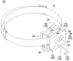
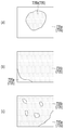
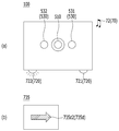
도 1은, 본 발명의 일 실시예에 따른 열화상 감지 디바이스(100)를 나타낸 도면이다. 열화상 감지 디바이스(100)는, “잔불 감지 디바이스” 또는 “잔불 알람 디바이스”라 칭할 수 있다.1 is a view showing a thermal
도 1을 참조하면, 열화상 감지 디바이스(100)는, 바디(200, 300)를 포함할 수 있다. 바디(200, 300)는, 열화상 감지 디바이스(100)의 전체적인 외관을 형성할 수 있다. 바디(200, 300)의 내외부에 다수의 부품이 장착되거나 수용될 수 있다. 바디(200, 300)는, 복수 개로 구분될 수 있다. 예를 들어 바디(200, 300)는, 제1 바디(200)와 제2 바디(300)를 포함할 수 있다. 제2 바디(300)는, 제1 바디(200)에 결합되거나 연결될 수 있다.Referring to FIG. 1, the thermal
바디(200, 300)는, 제1 바디(200)와 제2 바디(300) 중 적어도 하나를 의미할 수 있다. 바디(200, 300)는, 밴드(50)에 연결되거나 결합될 수 있다. 밴드(50)는, 사용자의 머리 등에 착용될 수 있다. 다른 예로서, 바디(200, 300)는, 사용자가 착용하는 헬멧에 결합되어 사용될 수 있다.The
제1 바디(200)는, 제1 프레임(210)을 포함할 수 있다. 제1 프레임(210)은, 제1 바디(200)의 골격을 형성할 수 있다. 제1 프레임(210)은, 밴드(50)에 연결되거나 결합될 수 있다.The
제1 바디(200)는, 제1 조작부(240)를 포함할 수 있다. 제1 조작부(240)는, 사용자로부터 입력을 획득할 수 있다. 이런 의미에서, 제1 조작부(240)는 입력 유닛(540)에 포함될 수 있다. 제1 조작부(240)는, 예를 들어, 열화상 감지 디바이스(100)의 전원 스위치일 수 있다.The
제2 바디(300)는, 제2 프레임(310)을 포함할 수 있다. 제2 프레임(310)은 제1 바디(200)의 전방에 위치할 수 있다. 제2 프레임(310)은, 제2 바디(300)의 골격을 형성할 수 있다. 제2 프레임(310)은, 제1 바디(200)에 결합될 수 있다.The
제2 바디(300)는, 전면(330, 前面)을 형성할 수 있다. 전면(330)은, 제2 프레임(310)에 형성될 수 있다. 전면(330)은, 열화상 감지 디바이스(100)의 전방을 마주할 수 있다.The
제2 바디(300)는, 제2 조작부(350)를 포함할 수 있다. 제2 조작부(350)는, 사용자로부터 입력을 획득할 수 있다. 제2 조작부(350)는, 제2 프레임(310)에 위치할 수 있다. 제2 조작부(350)는, 예를 들어, 모드(mode)의 변환 등에 관한 입력을 획득할 수 있다.The
열화상 감지 디바이스(100)는, 케이블(CB)을 포함할 수 있다. 케이블(CB)은, 제1 바디(200)에서 연장되어 제2 바디(300)로 이어질 수 있다. 케이블(CB)은, 전력 또는/및 신호를 전송할 수 있다.The thermal
열화상 감지 디바이스(100)는, 카메라 유닛(510)을 포함할 수 있다. 카메라 유닛(510)은, 제2 바디(300)에 결합될 수 있다. 카메라 유닛(510)은, 예를 들어, 제2 바디(300)의 전면(330)에 위치할 수 있다. 카메라 유닛(510)은, 전방에 위치한 사물의 이미지를 획득할 수 있다. 예를 들어, 카메라 유닛(510)은, 사물의 열화상 이미지를 획득할 수 있다.The thermal
도면에 도시되지 않았으나, 열화상 감지 디바이스(100)는, 비주얼 카메라(Visual camera)를 포함할 수 있다. 비주얼 카메라는, “카메라”일 수 있다. 비주얼 카메라는, 영상을 녹화할 수 있다. 비주얼 카메라는, 영상을 캡쳐할 수 있다. 비주얼 카메라를 통해 획득된 영상 또는 캡쳐된 이미지는, 통신 유닛(800)을 통해 외부 기기로 전송될 수 있다. 외부 기기로 전송되는 영상 또는 이미지는, 실시간 영상 또는 이미지일 수 있다. 비주얼 카메라에서 획득하는 영상은, 카메라 유닛(510)에서 획득하는 영상과 중첩될 수 있다.Although not shown in the drawings, the thermal
열화상 감지 디바이스(100)는, 조명 유닛(530)을 포함할 수 있다. 조명 유닛(530)은 광(光)을 제공할 수 있다. 조명 유닛(530)은, 제2 바디(300)의 전면(330)에 위치할 수 있다. 조명 유닛(530)은, 카메라 유닛(510)에 인접할 수 있다.The thermal
조명 유닛(530)은, 복수 개로 제공될 수 있다. 예를 들어, 조명 유닛(530)은, 제1 조명 모듈(531)과 제2 조명 모듈(532)을 포함할 수 있다. 카메라 유닛(510)은, 제1 조명 모듈(531)과 제2 조명 모듈(532)의 사이에 위치할 수 있다.A plurality of
열화상 감지 디바이스(100)는, 디스플레이 유닛(730)을 포함할 수 있다. 디스플레이 유닛(730)은, 이미지(image) 또는 정보를 표시할 수 있다. 디스플레이 유닛(730)은, 디스플레이 바디(733)를 포함할 수 있다. 디스플레이 바디(733)는, 제2 바디(300)의 전방에 위치할 수 있다.The thermal
디스플레이 유닛(730)은, 연결 부재(731)를 포함할 수 있다. 연결 부재(731)는, 전면(330)에서 연장되어 디스플레이 바디(733)로 이어질 수 있다. 연결 부재(731)는 전면(330)에 착탈될 수 있다. 연결 부재(731)는, 제2 바디(300)와 디스플레이 바디(733)의 사이에 위치할 수 있다. 연결 부재(731)는, 제2 바디(300)에 대한 디스플레이 바디(733)의 상대적 위치를 유지시킬 수 있다. 연결 부재(731)는, 가요성(flexible)일 수 있다. 디스플레이 바디(733)의 제2 바디(300)에 대한 상대적 위치는, 연결 부재(731)의 조정을 통해, 조절될 수 있다.The
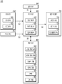
도 2는, 본 발명의 일 실시예에 따른 열화상 감지 디바이스(100)의 블록도를 나타낸 도면이다. 열화상 감지 디바이스(100)는, 열화상 이미지를 획득하여 처리한 이후 열원(heat source)의 위치에 관한 정보를 추출할 수 있다. 예를 들어 열화상 감지 디바이스(100)는, 산불의 진화 작업시 잔불의 위치에 관한 정보를 추출할 수 있다.2 is a block diagram of a thermal
도 2를 참조하면, 열화상 감지 디바이스(100)는, 제어 유닛(600)을 포함할 수 있다. 제어 유닛(600)은, 회로 기판, PCB, FPCB, 논리 회로, 컴퓨터 등에 의해 구현될 수 있다. 제어 유닛(600)은, 카메라 유닛(510)으로부터 제공받은 열화상 이미지를 처리할 수 있다.Referring to FIG. 2, the thermal
제어 유닛(600)은, 영상 처리부(610)를 포함할 수 있다. 영상 처리부(610)는, 카메라 유닛(510)으로부터 제공받은 열화상 이미지를 가공할 수 있다. 예를 들어, 영상 처리부(610)는, 열화상 이미지에서 주변 온도 보다 특정 온도 이상 높은 영역(이하 “관심 영역” 또는 “잔불 영역”)과 나머지 부분을 다르게 처리할 수 있다.The
제어 유닛(600)은, 잔불 영역 판단부(620)를 포함할 수 있다. 잔불 영역 판단부(620)는, “판단부”라 칭할 수 있다. 잔불 영역 판단부(620)는, 관심 영역의 형상 또는 위치로부터 관심 영역의 위치를 판단할 수 있다. 관심 영역이 좌측에 치우친 경우, 잔불 영역 판단부(620)는 관심 영역이 좌측에 위치함을 판단할 수 있다.The
제어 유닛(600)은, 알람 형성부(630)를 포함할 수 있다. 알람 형성부(630)는, 잔불 영역 판단부(620)에 의해 판단된 관심 영역의 위치 정보에 기초하여, 알람을 형성할 수 있다.The
열화상 감지 디바이스(100)는, 입력 유닛(540)을 포함할 수 있다. 입력 유닛(540)은, 사용자로부터 입력(input)을 획득할 수 있다. 입력 유닛(540)은, 획득한 입력에 기초하여 제1 신호(S1)를 생성할 수 있다. 입력 유닛(540)은, 제1 신호(S1)를 제어 유닛(600)에 전송할 수 있다.The thermal
열화상 감지 디바이스(100)는, 센서 유닛(520)을 포함할 수 있다. 센서 유닛(520)은, 온도 센서(521)를 포함할 수 있다. 온도 센서(521)는, 열화상 감지 디바이스(100)가 위치하는 공간의 온도를 측정할 수 있다. 센서 유닛(520)은, 조도 센서(522)를 포함할 수 있다. 조도 센서(522)는, 열화상 감지 디바이스(100)가 위치하는 공간의 조도를 측정할 수 있다. 센서 유닛(520)은, 감지된 온도와 측정된 조도 중 적어도 하나에 기초하여 제2 신호(S2)를 생성할 수 있다. 센서 유닛(520)은, 제2 신호(S2)를 제어 유닛(600)에 제공할 수 있다.The thermal
열화상 감지 디바이스(100)는, 카메라 유닛(510)을 포함할 수 있다. 카메라 유닛(510)은, 열화상 이미지를 획득할 수 있다. 카메라 유닛(510)은, 획득된 이미지에 관한 정보를 포함하는 제3 신호(S3)를 생성할 수 있다. 카메라 유닛(510)은, 제3 신호(S3)를 제어 유닛(600)에 제공할 수 있다.The thermal
제어 유닛(600)은, 입력 신호(S1, S2, S3)에 기초하여 출력 신호(S4)를 생성할 수 있다. 출력 신호(S4)는, “제4 신호”라 칭할 수 있다. 입력 신호(S1, S2, S3)는, 제1 신호(S1), 제2 신호(S2), 그리고 제3 신호(S3) 중 적어도 하나를 의미할 수 있다. 후술될 제5 신호(S5)가 제어 유닛(600)에 제공되는 경우, 입력 신호(S1, S2, S3, S4)는, 제1 신호(S1), 제2 신호(S2), 제3 신호(S3), 그리고 제5 신호(S5) 중 적어도 하나를 의미할 수 있다. 후술될 제5 신호(S5)가 제어 유닛(600)에서 생성되는 경우, 출력 신호(S4, S5)는, 제4 신호(S4)와 제5 신호(S5) 중 적어도 하나를 의미할 수 있다.The
열화상 감지 디바이스(100)는, 알람 어셈블리(700)를 포함할 수 있다. 알람 어셈블리(700)는, 제어 유닛(600)으로부터 제4 신호(S4)를 수신할 수 있다. 제4 신호(S4)는, 알람 어셈블리(700)의 작동에 관한 정보를 포함할 수 있다.The thermal
알람 어셈블리(700)는, 사운드 유닛(710, sound unit)을 포함할 수 있다. 사운드 유닛(710)은, 제4 신호(S4)에 포함된 정보를 음성 또는 음향으로 변환할 수 있다. 알람 어셈블리(700)는, 플리커 유닛(720, flicker unit)을 포함할 수 있다. 플리커 유닛(720)은, 제4 신호(S4)에 포함된 정보를 깜빡임으로 변환할 수 있다. 알람 어셈블리(700)는, 디스플레이 유닛(730)을 포함할 수 있다. 디스플레이 유닛(730)은, 제4 신호(S4)에 포함된 정보를 이미지로 변환할 수 있다. 알람 어셈블리(700)는, 음향, 깜빡임, 그리고 이미지로부터 관심 영역의 위치 정보를 제공할 수 있다.The
열화상 감지 디바이스(100)는, 통신 유닛(800)을 포함할 수 있다. 통신 유닛(800)은, 외부 기기와 신호 또는 정보를 송수신할 수 있다. 통신 유닛(800)은, 근거리 통신 모듈(810)을 포함할 수 있다. 근거리 통신 모듈(810)은, 블루투스(Bluetooth), NFC(Near Field Communication), 비콘(beacon), 지그비, 와이파이, 무선랜 중 적어도 하나의 방식에 의해 구현될 수 있다.The thermal
통신 유닛(800)은, 원거리 통신 모듈(820)을 포함할 수 있다. 원거리 통신 모듈(820)은, LPWAN(Low Power Wide Area Network), 3G(Third Generation), LTE(Long Term Evolution), SigFox, LoRa, 5G(Fifth Generation) 중 적어도 하나의 방식에 의해 구현될 수 있다.The
통신 유닛(800)은, 입출력 모듈(830)을 포함할 수 있다. 입출력 모듈(830)은, “입출력 포트” 또는 “Input/Output Port”라 칭할 수 있다. 입출력 모듈(830)은, 예를 들어, SD카드 포트 또는/및 USB 포트를 포함할 수 있다.The
통신 유닛(800)은, GPS 모듈(840)을 포함할 수 있다. GPS 모듈(840)은, 열화상 감지 디바이스(100)의 위치 정보를 획득할 수 있다. GPS 모듈(840)은, 예를 들어, 열화상 감지 디바이스(100)의 위치 정보를 실시간으로 획득할 수 있다. GPS 모듈(840)은, 다른 예를 들어, 열화상 감지 디바이스(100)의 위치 정보를 간헐적으로 획득할 수 있다. 예를 들어, GPS 모듈(840)은, GPS 신호가 약한 지역에 진입하게 되면, GPS 신호를 간헐적으로 획득할 수 있다. GPS 신호는, 열화상 감지 디바이스(100)의 위치 정보를 포함할 수 있다.The
통신 유닛(800)은, 예를 들어, IMU(850, inertial measurement unit)를 포함할 수 있다. 통신 유닛(800)은, IMU(850)를 통해, 열화상 감지 디바이스(100)의 자세(attitude)에 관한 정보를 획득할 수 있다. 예를 들어 IMU(850)는, 카메라 유닛(510)이 향하는 방향(orientation)에 관한 정보를 획득할 수 있다. 카메라 유닛(510)이 향하는 방향에 관한 정보는, 잔불 영역의 위치에 관한 정보를 추출하는데 이용될 수 있다.The
IMU(850)는, “관성 측정 장치”로서, 관성 정보를 획득할 수 있다. 예를 들어, IMU(850)는, 선형 가속도와 회전 속도를 감지할 수 있다. IMU(850)는, 예를 들어, 자이로스코프, 가속도계, 그리고 지자기센서 중에서 적어도 하나를 포함할 수 있다. IMU(850)는, 예를 들어 지자기센서를 구비하여, 카메라 유닛(510)이 향하는 방위각에 관한 정보를 획득할 수 있다. IMU(850)는, 다른 예를 들어 자이로스코프(또는 자이로센서)를 구비하여, 카메라 유닛(510)이 가리키는 방향(orientation)에 관한 정보를 획득할 수 있다.The
이로써, 제어 유닛(600)은, IMU(850)를 통해 카메라 유닛(510)의 자세(attitude) 뿐만 아니라 선형 속도를 감지할 수 있다. 따라서 제어 유닛(600)은, IMU(850)를 통해, 열화상 감지 디바이스(100)의 위치 변화를 감지할 수 있다.Accordingly, the
예를 들어, GPS 모듈(840)이 실시간으로 GPS 신호를 획득하기 어려운 경우가 고려될 수 있다. 이와 같은 경우, 제어 유닛(600)은, GPS 모듈(840)로부터 획득된 GPS 신호를 기초로 열화상 감지 디바이스(100)의 초기 위치를 설정하고, IMU(850)로부터 획득된 위치 변화량과 초기 위치를 기초로 열화상 감지 디바이스(100)의 현재 위치에 관한 정보를 획득할 수 있다.For example, a case where the
통신 유닛(800)은, 고도 모듈(860, altitude module)을 포함할 수 있다. 고도 모듈(860)은, 열화상 감지 디바이스(100)의 고도 정보를 획득할 수 있다. 고도 모듈(860)은, 기압 정보를 이용하여 열화상 감지 디바이스(100)의 고도 정보를 획득할 수 있다.The
제어 유닛(600)은, GPS 모듈(840), IMU(850), 그리고 고도 모듈(860) 중 적어도 하나에 기초하여, 열화상 감지 디바이스(100)의 위치 정보를 획득할 수 있다. IMU(850)를 통해 추측된 위치는, GPS 모듈(840)이 새로운 GPS 신호를 수신하면, 새로운 GPS 신호에 포함된 현재 위치로 갱신될 수 있다.The
열화상 감지 디바이스(100)의 현재 위치가 설정되면, 제어 유닛(600)은, 열화상 감지 디바이스(100)의 현재 위치와 카메라 유닛(510)의 방향(orientation) 정보에 기초하여, 잔불 영역의 위치를 산출할 수 있다.When the current position of the thermal
통신 유닛(800)은, 제어 유닛(600)과 신호를 송수신할 수 있다. 예를 들어 통신 유닛(800)은, 제5 신호(S5)를 제어 유닛(600)으로부터 수신할 수 있다. 이 경우, 통신 유닛(800)은 제5 신호(S5)에 대응된 작동을 수행할 수 있다. 예를 들어, 통신 유닛(800)은, 관심 영역에 관한 정보를 포함하는 제5 신호(S5)를 외부 기기(예를 들어 서버 또는 이동단말기)에 전송할 수 있다.The
예를 들어 통신 유닛(800)은, 제5 신호(S5)를 생성하여 제어 유닛(600)에 제공할 수 있다. 이 경우, 제5 신호(S5)는, 통신 유닛(800)이 외부 기기와의 통신을 통해 획득한 정보를 포함할 수 있으며, 입력 신호에 포함될 수 있다.For example, the
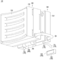
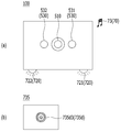
도 3은 도 1에 도시된 열화상 감지 디바이스(100)를 다른 각도에서 나타낸 도면이다.3 is a view showing the thermal
도 3을 참조하면, 열화상 감지 디바이스(100)는 힌지 결합부(400)를 포함할 수 있다. 힌지 결합부(400)는 힌지(430)를 포함할 수 있다. 힌지(430)는, 제1 바디(200)와 제2 바디(300)의 사이에 위치할 수 있다. 힌지 결합부(400)는, 제1 바디(200)와 제2 바디(300)를 결합할 수 있다. 제2 바디(300)는 제1 바디(200)에 힌지 결합(hingedly coupled)될 수 있다.Referring to FIG. 3, the thermal
제2 바디(300)는, 힌지 결합부(400)에 의해, 제1 바디(200)에 회전 가능하게 결합될 수 있다. 제2 바디(300)가 힌지(430)를 중심으로 회전하면, 제2 바디(300)의 제1 바디(200)에 대한 상대적 위치는 변경될 수 있다.The
힌지(430)는, 일정 크기 이하의 외력에 대하여 자세를 유지하되 일정 크기 초과의 외력에 대하여 회전될 수 있다. 예를 들어, 힌지(430)는, 토크 힌지(torque hinge)를 포함할 수 있다. 이로써 힌지(430)에 의한 제1 바디(200)와 제2 바디(300)의 상대적 위치 관계 설정이 용이할 수 있다.The
열화상 감지 디바이스(100)는, 플리커 유닛(720)을 포함할 수 있다. 플리커 유닛(720)은, 제2 바디(300)의 일측에 위치할 수 있다. 제2 바디(300)는, 하면(340)을 포함할 수 있다. 제2 바디(300)의 하면(340)은, 제2 프레임(310)의 바닥(bottom)을 형성할 수 있다. 예를 들어, 플리커 유닛(720)은, 제2 바디(300)의 하면(340)에 위치할 수 있다. 열화상 감지 디바이스(100)가 밴드(50, 도 1 참조)에 의해 사용자의 머리(특히 이마)에 착용된 상태에서 플리커 유닛(720)이 깜빡이면, 플리커 유닛(720)은 사용자의 눈(eye)에 깜빡임을 효과적으로 제공할 수 있다.The thermal
플리커 유닛(720)은, 복수 개로 제공될 수 있다. 예를 들어 플리커 유닛(720)은, 제1 플리커 모듈(721)과 제2 플리커 모듈(722)을 포함할 수 있다. 제1 플리커 모듈(721)은, 제2 플리커 모듈(722)과 이격될 수 있다. 제1 플리커 모듈(721)은, 열화상 감지 디바이스(100)가 사용자의 이마 등에 착용된 상태에서, 제2 플리커 모듈(722)의 좌측(左側)에 위치할 수 있다.A plurality of
제1 바디(200)는 착용부(220)를 포함할 수 있다. 착용부(220)는, 제1 바디(220)의 후면(後面)에 위치할 수 있다. 열화상 감지 디바이스(100)가 사용자의 이마 등에 착용된 상태에서, 착용부(220)는 사용자에 접할 수 있다. 열화상 감지 디바이스(100)가 사용자의 이마 등에 착용된 상태에서, 착용부(220)는 사용자와 제1 프레임(210)의 사이에 위치할 수 있다. 착용부(220)는 예를 들어 스펀지를 포함할 수 있다. 착용부(220)는 탄성을 가질 수 있다.The
디스플레이 유닛(730)은 디스플레이 스크린(735)을 포함할 수 있다. 디스플레이 스크린(735)은, 디스플레이 바디(733)에 위치할 수 있다. 디스플레이 스크린(735)은, 후방을 향하여 이미지를 표시할 수 있다.The
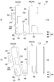
도 4는, 본 발명의 일 실시예에 따른 열화상 감지 디바이스(100)를 측면에서 바라본 모습을 나타낸 도면이다. 도 4에서 설명의 편의를 위하여 디스플레이 유닛(730, 도 1 참조)의 표시는 생략될 수 있다.4 is a view showing a side view of the thermal
도 4를 참조하면, 제1 바디(200)는 제2 바디(300)의 후방에 위치할 수 있다. 제1 바디(200)는 제1 대향면(230)을 포함할 수 있다. 제1 대향면(230)은 제1 프레임(210)에 형성될 수 있다. 제1 대향면(230)은 제2 바디(300)를 마주할 수 있다. 제1 대향면(230)은, 착용부(220)의 맞은편에 위치할 수 있다.Referring to FIG. 4, the
제1 바디(200)는 전원 연결부(250)를 포함할 수 있다. 전원 연결부(250)는, 별도의 케이블에 연결되어 외부 전원으로부터 전력을 제공받을 수 있다. 도 4에서 전원 연결부(250)는 별도의 보호 커버에 의해 보호될 수 있다. 제1 바디(200)는 제1 조작부(240)를 포함할 수 있다.The
제2 바디(300)는 제2 대향면(320)을 포함할 수 있다. 제2 대향면(320)은, 제2 바디(300)의 후면(後面)을 형성할 수 있다. 제2 대향면(320)은 제1 바디(200)를 마주할 수 있다. 예를 들어 제2 대향면(320)은 제1 대향면(230)을 마주할 수 있다. 제2 대향면(320)은, 전면(330)의 맞은편에 위치할 수 있다.The
제2 바디(300)는 이어폰 잭(360)을 포함할 수 있다. 이어폰 잭(360)은 외부의 스피커 또는 이어폰에 연결되어 음향 정보를 제공할 수 있다. 도 4에서 이어폰 잭(360)은 별도의 보호 커버에 의해 보호될 수 있다.The
카메라 유닛(510) 또는/및 조명 유닛(530)은, 전면(330)에 위치할 수 있다. 플리커 유닛(720)은, 하면(340)에 위치할 수 있다.The
힌지 결합부(400)는, 제1 결합부(410)와 제2 결합부(420)를 포함할 수 있다. 제1 결합부(410)는, 제1 바디(200)에 결합될 수 있다. 제2 결합부(420)는, 제2 바디(300)에 결합될 수 있다. 힌지(430)는, 제1 결합부(410)와 제2 결합부(420)를 결합시킬 수 있다. 예를 들어, 제1 결합부(410) 또는/및 제2 결합부(420)는, 힌지(430)를 중심으로 회전할 수 있다. 제1 결합부(410)를 기준으로 살펴보면, 제2 결합부(420)는, 힌지(430)를 중심으로 회전하여 제1 결합부(410)에 대한 상대적 위치 또는/및 자세(attitude)를 형성할 수 있다.The
예를 들어, 도 4의 (a)를 참조하면, 제2 대향면(320)은 제1 대향면(230)을 정면으로 마주할 수 있다. 제2 대향면(320)과 제1 대향면(230)이 형성하는 각도는, 힌지 결합부(400)의 작동에 의존할 수 있다.For example, referring to (a) of FIG. 4, the second opposing
도 4의 (b)를 참조하면, 제2 결합부(420)가 힌지(430)를 중심으로 회전하면, 제2 대향면(320)은 제1 대향면(230)을 비스듬히 마주할 수 있다. 이 경우, 카메라 유닛(510)은 전하방(前下方)을 향할 수 있다. 즉 카메라 유닛(510)이 향하는 시선은 힌지 결합부(400)의 작동에 의존할 수 있다.Referring to FIG. 4B, when the
도 5 및 6은, 본 발명의 일 실시예에 따른 영상 처리부(610, 도 2 참조)가 열화상 이미지를 처리하여 관심 영역을 나타낸 도면이다.5 and 6 are views illustrating an area of interest by processing a thermal image by an image processing unit 610 (see FIG. 2) according to an embodiment of the present invention.
도 5 및 6을 참조하면, 제어 유닛(600, 도 2 참조) 또는 영상 처리부(610, 도 2 참조)는, 카메라 유닛(510, 도 2 참조)으로부터 열화상 이미지를 제공받을 수 있다. 영상 처리부(610, 도 2 참조)가 열화상 이미지를 가공한 이후의 이미지는 디스플레이 스크린(735, 도 3 참조)에 표시될 수 있다. 영상 처리부(610, 도 2 참조)는 열화상 이미지의 각 지점의 온도에 관한 정보를 획득할 수 있다. 영상 처리부(610, 도 2 참조)가 열화상 이미지를 가공한 이후의 이미지는, 배경 영역(735a)과 잔불 영역(735b)을 포함할 수 있다.5 and 6, the control unit 600 (see FIG. 2) or the image processing unit 610 (see FIG. 2) may receive a thermal image from the camera unit 510 (see FIG. 2 ). The image after the image processing unit 610 (see FIG. 2) processes the thermal image may be displayed on the display screen 735 (see FIG. 3). The image processing unit 610 (see FIG. 2) may obtain information about the temperature of each point of the thermal image. The image after the image processor 610 (see FIG. 2) processes the thermal image may include a
잔불 영역(735b)은, 열화상 이미지 중에서 주변 온도 보다 특정 온도 이상 높은 온도를 가지는 영역을 의미할 수 있다. 배경 영역(735a)은, 잔불 영역(735b)을 제외한 나머지 영역을 의미할 수 있다.The remaining
도 5의 (a)를 참조하면, 잔불 영역(735b)은 디스플레이 스크린(735)의 왼편에 치우칠 수 있다. 또는 잔불 영역(735b)이 디스플레이 스크린(735)의 좌측변에 접할 수 있다. 이 경우, 잔불 영역 판단부(620, 도 2 참조)는, 잔불 영역(735b)이 카메라 유닛(510, 도 2 참조)의 시선에서 좌측에 위치한다고 판단할 수 있다.Referring to FIG. 5A, the remaining
도 5의 (b)를 참조하면, 잔불 영역(735b)은 디스플레이 스크린(735)의 오른편에 치우칠 수 있다. 또는 잔불 영역(735b)이 디스플레이 스크린(735)의 우측변에 접할 수 있다. 이 경우, 잔불 영역 판단부(620, 도 2 참조)는, 잔불 영역(735b)이 카메라 유닛(510, 도 2 참조)의 시선에서 우측에 위치한다고 판단할 수 있다.Referring to FIG. 5B, the remaining
도 5의 (c)를 참조하면, 잔불 영역(735b)은 디스플레이 스크린(735)의 아래쪽에 치우칠 수 있다. 또는 잔불 영역(735b)이 디스플레이 스크린(735)의 하측변에 접할 수 있다. 이 경우, 잔불 영역 판단부(620, 도 2 참조)는, 잔불 영역(735b)이 카메라 유닛(510, 도 2 참조)의 시선에서 후방에 위치한다고 판단할 수 있다.Referring to (c) of FIG. 5, the remaining
도 5의 (d)를 참조하면, 잔불 영역(735b)은 디스플레이 스크린(735)의 위쪽에 치우칠 수 있다. 또는 잔불 영역(735b)이 디스플레이 스크린(735)의 상측변에 접할 수 있다. 이 경우, 잔불 영역 판단부(620, 도 2 참조)는, 잔불 영역(735b)이 카메라 유닛(510, 도 2 참조)의 시선에서 전방에 위치한다고 판단할 수 있다.Referring to FIG. 5D, the remaining
도 5의 (e)를 참조하면, 잔불 영역(735b)은 디스플레이 스크린(735)의 좌상(左上)에 치우칠 수 있다. 또는 잔불 영역(735b)이 디스플레이 스크린(735)의 좌상(左上) 코너에 접할 수 있다. 이 경우, 잔불 영역 판단부(620, 도 2 참조)는, 잔불 영역(735b)은 카메라 유닛(510, 도 2 참조)의 시선에서 좌상측(左上側)에 위치한다고 판단할 수 있다.Referring to (e) of FIG. 5, the remaining
도 5의 (f)를 참조하면, 잔불 영역(735b)은 디스플레이 스크린(735)의 좌하(左下)에 치우칠 수 있다. 또는 잔불 영역(735b)이 디스플레이 스크린(735)의 좌하(左下) 코너에 접할 수 있다. 이 경우, 잔불 영역 판단부(620, 도 2 참조)는, 잔불 영역(735b)이 카메라 유닛(510, 도 2 참조)의 시선에서 좌하측(左下側)에 위치한다고 판단할 수 있다.Referring to FIG. 5( f), the remaining
도 5의 (g)를 참조하면, 잔불 영역(735b)은 디스플레이 스크린(735)의 우하(右下)에 치우칠 수 있다. 또는 잔불 영역(735b)이 디스플레이 스크린(735)의 우하(右下) 코너에 접할 수 있다. 이 경우, 잔불 영역 판단부(620, 도 2 참조)는, 잔불 영역(735b)이 카메라 유닛(510, 도 2 참조)의 시선에서 우하측(右下側)에 위치한다고 판단할 수 있다.Referring to FIG. 5G, the remaining
도 5의 (h)를 참조하면, 잔불 영역(735b)은 디스플레이 스크린(735)의 우상(右上)에 치우칠 수 있다. 또는 잔불 영역(735b)이 디스플레이 스크린(735)의 우상(右上) 코너에 접할 수 있다. 이 경우, 잔불 영역 판단부(620, 도 2 참조)는, 잔불 영역(735b)이 카메라 유닛(510, 도 2 참조)의 시선에서 우상측(右上側)에 위치한다고 판단할 수 있다.Referring to (h) of FIG. 5, the remaining
도 6의 (a)를 참조하면, 잔불 영역(735b)은 디스플레이 스크린(735)의 중앙에 위치할 수 있다. 또는 잔불 영역(735b)은 디스플레이 스크린(735)의 어느 변에도 접하지 않을 수 있다. 이 경우, 잔불 영역 판단부(620, 도 2 참조)는, 잔불 영역(735b)이 카메라 유닛(510, 도 2 참조)의 시선에 위치한다고 판단할 수 있다.Referring to FIG. 6A, the remaining
도 6의 (b) 및 (c)를 참조하면, 잔불 영역(735b)은 디스플레이 스크린(735)의 영역 중 대다수에 분포될 수 있다. 예를 들어 잔불 영역(735b)은 디스플레이 스크린(735)의 영역의 특정 비율(예를 들어 80%) 이상을 차지할 수 있다. 이 경우, 잔불 영역 판단부(620, 도 2 참조)는, 잔불 영역(735b)이 카메라 유닛(510, 도 2 참조)의 시선에 위치한다고 판단할 수 있다.Referring to FIGS. 6B and 6C, the remaining
도 7 및 8은, 잔불 영역 판단부(620, 도 2 참조)가 관심 영역의 위치를 판단하는 방식을 예시한 도면이다.7 and 8 are diagrams illustrating a method in which the residual area determining unit 620 (see FIG. 2) determines the location of the region of interest.
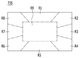
도 7을 참조하면, 디스플레이 스크린(735)은 복수 개의 영역으로 구획될 수 있다. 예를 들어, 디스플레이 스크린(735)은, 제1 영역(R1)을 포함할 수 있다. 제1 영역(R1)은, 디스플레이 스크린(735)의 상변에 인접할 수 있다. 디스플레이 스크린(735)은, 제2 영역(R2)을 포함할 수 있다. 제2 영역(R2)은 디스플레이 스크린(735)의 우상 코너에 인접할 수 있다. 디스플레이 스크린(735)은, 제3 영역(R3)을 포함할 수 있다. 제3 영역(R3)은 디스플레이 스크린(735)의 우변에 인접할 수 있다. 디스플레이 스크린(735)은, 제4 영역(R4)을 포함할 수 있다. 제4 영역(R4)은 디스플레이 스크린(735)의 우하 코너에 인접할 수 있다. 디스플레이 스크린(735)은, 제5 영역(R5)을 포함할 수 있다. 제5 영역(R5)은 디스플레이 스크린(735)의 하변에 인접할 수 있다. 디스플레이 스크린(735)은, 제6 영역(R6)을 포함할 수 있다. 제6 영역(R6)은 디스플레이 스크린(735)의 좌하 코너에 인접할 수 있다. 디스플레이 스크린(735)은, 제7 영역(R7)을 포함할 수 있다. 제7 영역(R7)은 디스플레이 스크린(735)의 좌변에 인접할 수 있다. 디스플레이 스크린(735)은, 제8 영역(R8)을 포함할 수 있다. 제8 영역(R8)은 디스플레이 스크린(735)의 좌상 코너에 인접할 수 있다. 디스플레이 스크린(735)은, 제9 영역(R9)을 포함할 수 있다. 제9 영역(R9)은 디스플레이 스크린(735)의 중심부에 위치할 수 있다.Referring to FIG. 7, the
잔불 영역 판단부(620, 도 2 참조)는, 잔불 영역(735b, 도 5 또는 6 참조)이 제1 내지 제9 영역(R1 ~ R9)과 중첩되는 비율에 기초하여, 잔불 영역(735b, 도 5 또는 6 참조)의 위치를 판단할 수 있다.The remaining area determining unit 620 (refer to FIG. 2 ), based on the ratio in which the remaining
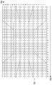
도 8을 참조하면, 디스플레이 스크린(735)은 가로축(PXH)과 세로축(PXV)에 의해 구획되는 복수 개의 픽셀(pixel)로 구성될 수 있다. 각각의 픽셀은, 도 7에 도시된 제1 내지 제9 영역(R1 ~ R9) 중 하나에 위치할 수 있다. 각각의 픽셀은, 위치하는 영역에 따라 다른 가중치를 가질 수 있다.Referring to FIG. 8, the
예를 들어 제3 영역(R3, 도 7 참조), 제7 영역(R7, 도 7 참조), 그리고 제9 영역(R9, 도 7 참조)에 위치하는 픽셀은 “3”의 가중치를 가질 수 있다. 예를 들어 제 영역(R1, 도 7 참조) 및 제5 영역(R5, 도 7 참조)에 위치하는 픽셀은 “1”의 가중치를 가질 수 있다. 예를 들어 제2 영역(R2, 도 7 참조), 제4 영역(R4, 도 7 참조), 제6 영역(R6, 도 7 참조), 그리고 제8 영역(R8, 도 7 참조)에 위치하는 픽셀은 “2”의 가중치를 가질 수 있다.For example, pixels located in the third area (see R3, see FIG. 7), the seventh area (see R7, see FIG. 7), and the pixel in the ninth area (see R9, see FIG. 7) may have a weight of “3”. . For example, pixels located in the first region R1 (see FIG. 7) and the fifth region R5 (see FIG. 7) may have a weight of “1”. For example, located in the second area (R2, see Fig. 7), the fourth area (R4, see Fig. 7), the sixth area (R6, see Fig. 7), and the eighth area (R8, see Fig. 7) The pixel may have a weight of “2”.
이와 같이 가중치를 달리하는 이유가 설명될 수 있다. 잔불 영역(735b, 도 5 또는 6 참조)의 위치는 카메라 유닛(510, 도 1 참조)의 시선에서 좌측 또는 우측에 위치하는 경우가 더 중요할 수 있다.The reason for different weights can be explained. It may be more important that the location of the remaining
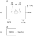
도 9 내지 11은, 알람 형성부(630, 도 2 참조)에 의해 알람 어셈블리(700)가 작동되는 모습을 나타낸 도면이다. 도 9 내지 11에서, 열화상 감지 디바이스(100)의 전방에서 카메라 유닛(510)이 관찰될 수 있으며, 디스플레이 스크린(735)의 후방에서 디스플레이 스크린(735)이 관찰될 수 있다.9 to 11 are views showing a state in which the
도 9를 참조하면, 영상 처리부(610, 도 2 참조)가 카메라 유닛(510, 도 1 참조)로부터 제공받은 열화상 이미지를 처리하여 생성한 잔불 영역(735b, 도 5 참조)은, 예를 들어 도 5의 (a)에 대응될 수 있다. 이 경우 잔불 영역 판단부(620, 도 2 참조)는, 잔불 영역(735b, 도 5 참조)이 카메라 유닛(510, 도 1 참조)의 시선을 기준으로 좌측에 위치함을 판단할 수 있다. 알람 형성부(630, 도 2 참조)는, 잔불 영역 판단부(620, 도 2 참조)의 판단을 기초로 제4 신호(S4, 도 2 참조)를 생성하여 알람 어셈블리(700, 도 2 참조)에 제공할 수 있다.9, the image processing unit 610 (see FIG. 2) is a residual area (735b, see FIG. 5) generated by processing the thermal image provided from the camera unit (510, see FIG. 1), for example It may correspond to Figure 5 (a). In this case, the remaining area determining unit 620 (see FIG. 2) may determine that the remaining
도 9의 (a)를 참조하면, 사운드 유닛(710, 도 2 참조)은 제4 신호(S4, 도 2 참조)에 대응된 음향(70)을 생성할 수 있다. 예를 들어 사운드 유닛(710, 도 2 참조)은 제1 음향(71)을 생성할 수 있다. 제1 음향(71)은, 잔불 영역(735b, 도 5 참조)이 카메라 유닛(510, 도 1 참조)의 시선을 기준으로 좌측에 위치하는 정보에 대응될 수 있다.Referring to (a) of FIG. 9, the sound unit 710 (see FIG. 2) may generate the sound 70 corresponding to the fourth signal S4 (see FIG. 2 ). For example, the sound unit 710 (see FIG. 2) may generate the
플리커 유닛(720)은, 제4 신호(S4, 도 2 참조)에 대응하여 깜빡일 수 있다. 예를 들어 제1 플리커 모듈(721)은 깜빡이고 제2 플리커 모듈(722)은 작동하지 않을 수 있다.The
도 9의 (b)를 참조하면, 디스플레이 스크린(735)은 제4 신호(S4, 도 2 참조)에 대응된 방향 지시 이미지(735d)를 생성할 수 있다. 예를 들어 디스플레이 스크린(735)은, 좌측을 가리키는 화살표 형상의 제1 방향 지시 이미지(735d1)를 표시할 수 있다.Referring to (b) of FIG. 9, the
도 10을 참조하면, 영상 처리부(610, 도 2 참조)가 카메라 유닛(510, 도 1 참조)로부터 제공받은 열화상 이미지를 처리하여 생성한 잔불 영역(735b, 도 5 참조)은, 예를 들어 도 5의 (b)에 대응될 수 있다. 이 경우 잔불 영역 판단부(620, 도 2 참조)는, 잔불 영역(735b, 도 5 참조)이 카메라 유닛(510, 도 1 참조)의 시선을 기준으로 우측에 위치함을 판단할 수 있다. 알람 형성부(630, 도 2 참조)는, 잔불 영역 판단부(620, 도 2 참조)의 판단을 기초로 제4 신호(S4, 도 2 참조)를 생성하여 알람 어셈블리(700, 도 2 참조)에 제공할 수 있다.Referring to FIG. 10, the
도 10의 (a)를 참조하면, 사운드 유닛(710, 도 2 참조)은 제4 신호(S4, 도 2 참조)에 대응된 음향(70)을 생성할 수 있다. 예를 들어 사운드 유닛(710, 도 2 참조)은 제2 음향(72)을 생성할 수 있다. 제2 음향(72)은, 잔불 영역(735b, 도 5 참조)이 카메라 유닛(510, 도 1 참조)의 시선을 기준으로 우측에 위치하는 정보에 대응될 수 있다.Referring to (a) of FIG. 10, the sound unit 710 (see FIG. 2) may generate the sound 70 corresponding to the fourth signal S4 (see FIG. 2 ). For example, the sound unit 710 (see FIG. 2) may generate the
플리커 유닛(720)은, 제4 신호(S4, 도 2 참조)에 대응하여 깜빡일 수 있다. 예를 들어 제2 플리커 모듈(722)은 깜빡이고 제1 플리커 모듈(721)은 작동하지 않을 수 있다.The
도 10의 (b)를 참조하면, 디스플레이 스크린(735)은 제4 신호(S4, 도 2 참조)에 대응된 방향 지시 이미지(735d)를 생성할 수 있다. 예를 들어 디스플레이 스크린(735)은, 우측을 가리키는 화살표 형상의 제2 방향 지시 이미지(735d2)를 표시할 수 있다.Referring to (b) of FIG. 10, the
도 9 및 도 10을 참조하면, 디스플레이 스크린(735)은 열화상 이미지에서 추출된 각 지점의 온도 중 가장 높은 온도를 표시할 수 있다. 이로써, 디스플레이 스크린(735)은, 잔불 영역(735b, 도 5 참조)의 대략적인 상황을 나타낼 수 있다. 즉 사용자(user)는 디스플레이 스크린(735)으로부터 잔불이 위치한 영역의 대략적인 상황 정보를 제공받을 수 있다.9 and 10, the
도 11을 참조하면, 영상 처리부(610, 도 2 참조)가 카메라 유닛(510, 도 1 참조)로부터 제공받은 열화상 이미지를 처리하여 생성한 잔불 영역(735b, 도 6 참조)은, 예를 들어 도 6에 대응될 수 있다. 이 경우 잔불 영역 판단부(620, 도 2 참조)는, 잔불 영역(735b, 도 6 참조)이 카메라 유닛(510, 도 1 참조)의 시선을 기준으로 중심부에 위치함을 판단할 수 있다. 알람 형성부(630, 도 2 참조)는, 잔불 영역 판단부(620, 도 2 참조)의 판단을 기초로 제4 신호(S4, 도 2 참조)를 생성하여 알람 어셈블리(700, 도 2 참조)에 제공할 수 있다.Referring to FIG. 11, the
도 11의 (a)를 참조하면, 사운드 유닛(710, 도 2 참조)은 제4 신호(S4, 도 2 참조)에 대응된 음향(70)을 생성할 수 있다. 예를 들어 사운드 유닛(710, 도 2 참조)은 제3 음향(73)을 생성할 수 있다. 제3 음향(73)은, 잔불 영역(735b, 도 6 참조)이 카메라 유닛(510, 도 1 참조)의 시선을 기준으로 중심부에 위치하는 정보에 대응될 수 있다.Referring to (a) of FIG. 11, the sound unit 710 (see FIG. 2) may generate the sound 70 corresponding to the fourth signal S4 (see FIG. 2 ). For example, the sound unit 710 (see FIG. 2) may generate the
플리커 유닛(720)은, 제4 신호(S4, 도 2 참조)에 대응하여 깜빡일 수 있다. 예를 들어 제1 플리커 모듈(721)과 제2 플리커 모듈(722)이 모두 깜빡일 수 있다.The
도 11의 (b)를 참조하면, 디스플레이 스크린(735)은 제4 신호(S4, 도 2 참조)에 대응된 방향 지시 이미지(735d)를 생성할 수 있다. 예를 들어 디스플레이 스크린(735)은, 원(圓) 형상의 제3 방향 지시 이미지(735d3)를 표시할 수 있다.Referring to FIG. 11B, the
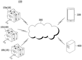
도 12는, 본 발명의 일 실시예에 따른 통제 시스템(1000)을 나타낸 도면이다.12 is a view showing a
도 12를 참조하면, 통제 시스템(1000)은, 적어도 하나의 열화상 감지 디바이스(100)를 포함할 수 있다. 예를 들어 통제 시스템(1000)은, 제1 열화상 감지 디바이스(100a), 제2 열화상 감지 디바이스(100b), 그리고 제3 열화상 감지 디바이스(100c)를 포함할 수 있다. 열화상 감지 디바이스(100)는, GPS 모듈(840, 도 2 참조)을 통해 실시간으로 위치 정보를 획득할 수 있다. 열화상 감지 디바이스(100)는, 카메라 유닛(510, 도 1 참조)과 제어 유닛(600, 도 2 참조)을 통해 실시간으로 잔불 영역(735b, 도 5 또는 6 참조)의 유무(有無) 정보를 획득할 수 있다. 열화상 감지 디바이스(100)는, 네트워크(2000)를 통해, 단말기(3000) 또는/및 서버(4000)와 통신할 수 있다.Referring to FIG. 12, the
통제 시스템(1000)은, 단말기(3000)를 포함할 수 있다. 단말기(3000)는, 예를 들어, 이동 단말기(mobile terminal) 또는 스마트폰(smartphone)일 수 있다. 통제 시스템(1000)은, 서버(4000)를 포함할 수 있다. 서버(4000)는, 적어도 하나의 열화상 감지 디바이스(100)로부터 정보를 획득할 수 있다. 예를 들어, 서버(4000)는, 열화상 감지 디바이스(100)로부터 잔불 영역(735b, 도 5 또는 6 참조)의 유무(有無)에 관한 정보 또는/및 열화상 감지 디바이스(100)의 위치에 관한 정보를 획득할 수 있다.The
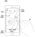
도 13은, 본 발명의 일 실시예에 따른 통제 시스템(1000)에서 작동되는 단말기(3000)의 모습을 나타낸 도면이다.13 is a view showing a state of the terminal 3000 operating in the
도 13을 참조하면, 단말기(3000)는 단말기 본체(3100)를 포함할 수 있다. 단말기 본체(3100)는 통신 모듈과 프로세서(processor)를 포함할 수 있다. 단말기 본체(31000)에 포함된 프로세서는, 특정 어플리케이션(application)을 구동시킬 수 있다. 단말기(3000)에서 구동되는 특정 어플리케이션은, “제1 어플리케이션”이라 칭할 수 있으며, 열화상 감지 디바이스(100, 도 12 참조)로부터 각종 정보를 제공받아 이미지를 생성할 수 있다.Referring to FIG. 13, the terminal 3000 may include a
단말기(3000)는, 단말기 스크린(3200)을 포함할 수 있다. 단말기 스크린(3200)은, 이미지를 표시할 수 있다. 예를 들어 단말기 스크린(3200)은, 제1 어플리케이션이 생성한 이미지를 표시할 수 있다. 제1 어플리케이션이 생성하는 이미지는, 맵(3210)을 포함할 수 있다. 맵(3210)은, 단말기 스크린(3200)에 표시될 수 있다. 맵(3210)은, 열화상 감지 디바이스(100, 도 12 참조)의 위치 정보에 대응되는 지역의 지도 정보를 포함할 수 있다. The terminal 3000 may include a
제1 어플리케이션이 생성하는 이미지는, 모니터링 스폿(3220, monitoring spot)을 포함할 수 있다. 모니터링 스폿(3220)은, 잔불 영역(735b)을 생성한 열화상 감지 디바이스(100, 도 12 참조)의 위치를 의미할 수 있다. 모니터링 스폿(3220)은 복수 개로 제공될 수 있다. 모니터링 스폿(3220)은 맵(3210)에 중첩되어 표시될 수 있다.The image generated by the first application may include a monitoring spot (3220). The
단말기 스크린(3200)의 영역은, 상태창(3230)을 포함할 수 있다. 제1 어플리케이션은, 상태창(3230)에 정보를 표시할 수 있다. 예를 들어 제1 어플리케이션은, 상태창(3230)에 모니터링 스폿(3220)의 개략적인 정보를 표시할 수 있다.The area of the
단말기 스크린(3200)은, 터치 입력(touch input)을 획득할 수 있다. 예를 들어 사용자(user)의 손(60)은, 모니터링 스폿(3220)을 터치할 수 있다. 제1 어플리케이션은, 터치 입력에 대응된 작동을 수행할 수 있다.The
도 14는, 터치 입력에 대응된 작동을 수행한 단말기(3000)의 모습을 나타낸 도면이다. 도 14를 참조하면, 제1 어플리케이션은 터치 입력(도 13 참조)에 대응된 모니터링 스폿(3220)에 관련된 정보를 상태창(3230)에 표시할 수 있다.14 is a diagram illustrating a state of the terminal 3000 performing an operation corresponding to a touch input. Referring to FIG. 14, the first application may display information related to the
도 12 내지 14를 참조하면, 통제 시스템(1000)은, 잔불 감시 및 제거 목적에 이용될 수 있다. 열화상 감지 디바이스(100)는 잔불의 유무 및 위치에 관한 정보를 획득할 수 있다. 열화상 감지 디바이스(100)는 서버(400)에 잔불의 유무 및 위치에 관한 정보를 제공할 수 있다. 서버(4000)는, 적어도 하나의 열화상 감지 디바이스(100)로부터 정보를 제공받아 취합하여 단말기(3000)에 제공할 수 있다.12 to 14, the
단말기(3000)는, 서버(4000)로부터 제공받은 정보에 기초하여 잔불의 위치 및/또는 상황에 관한 정보를 획득할 수 있다. 통제자(commander)는, 단말기 스크린(3200)에 표시되는 정보를 기초로, 잔불 제거 작업을 용이하게 관리할 수 있다. 예를 들어 통제자는, 단말기 스크린(3200)에 표시되는 정보를 기초로, 리소스(resource)를 효과적으로 분배할 수 있다.The terminal 3000 may obtain information regarding the location and/or situation of the balance based on the information provided from the
전술한 본 발명의 설명은 예시를 위한 것이며, 본 발명이 속하는 기술분야의 통상의 지식을 가진 자는 본 발명의 기술적 사상이나 필수적인 특징을 변경하지 않고서 다른 구체적인 형태로 쉽게 변형이 가능하다는 것을 이해할 수 있을 것이다. 그러므로 이상에서 기술한 실시예들은 모든 면에서 예시적인 것이며 한정적이 아닌 것으로 이해해야만 한다. 예를 들어, 단일형으로 설명되어 있는 각 구성 요소는 분산되어 실시될 수도 있으며, 마찬가지로 분산된 것으로 설명되어 있는 구성 요소들도 결합된 형태로 실시될 수 있다.The above description of the present invention is for illustration only, and those skilled in the art to which the present invention pertains can understand that the present invention can be easily modified into other specific forms without changing the technical spirit or essential features of the present invention. will be. Therefore, it should be understood that the embodiments described above are illustrative in all respects and not restrictive. For example, each component described as a single type may be implemented in a distributed manner, and similarly, components described as distributed may be implemented in a combined form.
본 발명의 범위는 후술하는 특허청구범위에 의하여 나타내어지며, 특허청구범위의 의미 및 범위 그리고 그 균등 개념으로부터 도출되는 모든 변경 또는 변형된 형태가 본 발명의 범위에 포함되는 것으로 해석되어야 한다.The scope of the present invention is indicated by the following claims, and all modifications or variations derived from the meaning and scope of the claims and their equivalent concepts should be interpreted to be included in the scope of the present invention.
100: 열화상 감지 디바이스 200: 제1 바디
300: 제2 바디 400: 힌지 결합부
510: 카메라 유닛 520: 센서 유닛
530: 조명 유닛 540: 입력 유닛
600: 제어 유닛 700: 알람 어셈블리
710: 사운드 유닛 720: 플리커 유닛
730: 디스플레이 유닛 800: 통신 유닛100: thermal image sensing device 200: first body
300: second body 400: hinge coupling
510: camera unit 520: sensor unit
530: lighting unit 540: input unit
600: control unit 700: alarm assembly
710: sound unit 720: flicker unit
730: display unit 800: communication unit
Claims (14)
바디;
상기 바디에 위치하며 주변 온도를 측정하는 온도 센서를 구비하는 센서 유닛;
상기 바디의 전면(前面)에 위치하며 열화상 이미지를 획득하는 카메라 유닛;
상기 바디에 위치하며, 상기 주변 온도를 기초로 상기 열화상 이미지를 처리하여 잔불 영역을 추출하되, 상기 열화상 이미지 중에서 상기 주변 온도 보다 특정 온도 이상 높은 온도를 가지는 영역을 상기 잔불 영역으로 설정하는 제어 유닛;
GPS 모듈과 IMU 중 적어도 하나를 구비하는, 통신 유닛; 그리고
상기 바디에 위치하고 상기 잔불 영역의 위치 정보에 대응된 알람을 제공하는 알람 어셈블리를 포함하고,
상기 GPS 모듈은 상기 열화상 감지 디바이스의 위치 정보를 획득하며,
상기 IMU는 상기 열화상 감지 디바이스의 자세 정보와 관성 정보 중 적어도 하나의 정보를 획득하고,
상기 제어 유닛은,
상기 통신 유닛이 획득한 정보에 기초하여 상기 잔불 영역의 위치 정보를 추출하는,
열화상 감지 디바이스.In the thermal imaging device,
body;
A sensor unit located in the body and having a temperature sensor for measuring ambient temperature;
A camera unit located on the front surface of the body and acquiring a thermal image;
Control located in the body and extracting a residual area by processing the thermal image based on the ambient temperature, but setting a region having a temperature higher than a specific temperature above the ambient temperature in the thermal image as the residual area unit;
A communication unit having at least one of a GPS module and an IMU; And
And an alarm assembly located in the body and providing an alarm corresponding to location information of the remaining area,
The GPS module acquires location information of the thermal image sensing device,
The IMU acquires at least one of attitude information and inertia information of the thermal image sensing device,
The control unit,
Extracting location information of the remaining area based on the information obtained by the communication unit,
Thermal imaging device.
상기 제어 유닛은,
상기 GPS 모듈에 의해 획득된 위치 정보에 포함된 위치를 초기 위치로 설정하고, 상기 IMU에 의해 획득된 관성 정보를 이용하여 위치 변화량을 산출하며, 상기 초기 위치와 상기 위치 변화량에 기초하여 상기 열화상 감지 디바이스의 현재 위치를 산출하는,
열화상 감지 디바이스.According to claim 1,
The control unit,
The position included in the location information obtained by the GPS module is set as an initial position, a position change amount is calculated using the inertia information obtained by the IMU, and the thermal image is based on the initial position and the position change amount. Calculating the current position of the sensing device,
Thermal imaging device.
상기 통신 유닛은,
상기 열화상 감지 디바이스의 고도(altitude) 정보를 획득하는 고도 모듈을 더 포함하고,
상기 제어 유닛은,
상기 GPS 모듈, 상기 IMU, 그리고 상기 고도 모듈 중 적어도 하나를 이용하여, 상기 열화상 감지 디바이스의 위치 정보를 획득하는,
열화상 감지 디바이스.According to claim 1,
The communication unit,
Further comprising an altitude module for obtaining the altitude (altitude) information of the thermal image sensing device,
The control unit,
Acquiring location information of the thermal image sensing device by using at least one of the GPS module, the IMU, and the altitude module,
Thermal imaging device.
상기 바디는,
제1 바디; 그리고
상기 제1 바디의 전방에 위치하며 상기 제1 바디에 힌지 결합(hingedly coupling)되는 제2 바디를 포함하고,
상기 카메라 유닛은,
상기 제2 바디의 전면(前面)에 위치하는,
열화상 감지 디바이스.According to claim 1,
The body,
A first body; And
It is located in front of the first body and includes a second body hinged to the first body (hingedly coupled),
The camera unit,
Located on the front surface of the second body,
Thermal imaging device.
상기 제1 바디와 상기 제2 바디를 결합시키는 힌지 결합부를 더 포함하고,
상기 힌지 결합부는,
상기 제1 바디에 결합되는 제1 결합부;
상기 제2 바디에 결합되는 제2 결합부; 그리고
상기 제1 결합부와 상기 제2 결합부를 회전 가능하게 결합시키는 힌지(hinge)를 포함하는,
열화상 감지 디바이스.According to claim 4,
Further comprising a hinge coupling portion for coupling the first body and the second body,
The hinge coupling portion,
A first coupling portion coupled to the first body;
A second coupling portion coupled to the second body; And
Including a hinge rotatably coupling the first coupling portion and the second coupling portion,
Thermal imaging device.
상기 제어 유닛은,
상기 열화상 이미지를 처리하여 잔불 영역을 추출하는 영상 처리부;
상기 잔불 영역의 위치를 판단하는 잔불 영역 판단부; 그리고
상기 잔불 영역의 위치에 대응된 신호를 상기 알람 어셈블리에 제공하는 알람 형성부를 포함하는,
열화상 감지 디바이스.According to claim 1,
The control unit,
An image processing unit which processes the thermal image to extract a residual area;
A remaining area determining unit determining a position of the remaining area; And
And an alarm forming unit providing a signal corresponding to the location of the remaining area to the alarm assembly,
Thermal imaging device.
상기 잔불 영역 판단부는,
상기 열화상 이미지의 영역을 복수 개의 영역으로 구획하고, 상기 구획된 영역과 상기 잔불 영역이 중첩된 영역에 기초하여 상기 잔불 영역의 위치를 판단하는,
열화상 감지 디바이스.The method of claim 6,
The remaining area determining unit,
The area of the thermal image is divided into a plurality of areas, and the position of the remaining area is determined based on an area where the divided area and the remaining area overlap.
Thermal imaging device.
상기 알람 어셈블리는,
상기 잔불 영역의 위치 정보에 대응된 이미지를 표시하는 디스플레이 유닛을 포함하며,
상기 디스플레이 유닛은,
상기 바디에서 전방으로 연장된 연결 부재;
상기 연결 부재에 결합되고 상기 바디의 전방에 위치하는 디스플레이 바디; 그리고
상기 디스플레이 바디에 결합되고 후방을 향하여 상기 잔불 영역의 위치 정보에 대응된 이미지를 표시하는 디스플레이 스크린을 포함하는,
열화상 감지 디바이스.According to claim 1,
The alarm assembly,
It includes a display unit for displaying an image corresponding to the location information of the remaining area,
The display unit,
A connecting member extending forward from the body;
A display body coupled to the connecting member and positioned in front of the body; And
And a display screen coupled to the display body and displaying an image corresponding to the location information of the remaining area toward the rear,
Thermal imaging device.
상기 알람 어셈블리는,
상기 바디의 하면(下面)에 위치하며 서로 이격된 제1 플리커 모듈과 제2 플리커 모듈을 구비하는 플리커 유닛을 더 포함하며,
상기 제1 플리커 모듈과 상기 제2 플리커 모듈은,
상기 잔불 영역의 위치 정보에 대응된 깜빡임(flicker)을 제공하는,
열화상 감지 디바이스.The method of claim 9,
The alarm assembly,
A flicker unit located on the lower surface of the body and having a first flicker module and a second flicker module spaced apart from each other, further comprising:
The first flicker module and the second flicker module,
Providing a flicker corresponding to the location information of the remaining area,
Thermal imaging device.
상기 잔불 영역에 관한 정보를 상기 네트워크를 통해 수신하여 표시하는 단말기를 포함하고,
상기 단말기는,
단말기 본체;
상기 단말기 본체에 위치하고 상기 잔불 영역에 관한 정보를 수신하는 통신 모듈;
상기 단말기 본체에 위치하고 이미지를 표시하는 단말기 스크린; 그리고
상기 잔불 영역에 관한 정보를 상기 단말기 스크린에 표시하는 제1 어플리케이션을 구동시키는 프로세서(processor)를 포함하고,
상기 열화상 감지 디바이스의 통신 유닛은,
상기 열화상 감지 디바이스의 위치 정보를 획득하는 GPS 모듈과, 상기 열화상 감지 디바이스의 관성 정보와 자세 정보 중 적어도 하나를 획득하는 IMU 중 적어도 하나를 구비하고,
상기 제어 유닛은,
상기 통신 유닛이 획득한 정보에 기초하여 상기 잔불 영역의 위치 정보를 추출하며,
상기 단말기 스크린은,
상기 잔불 영역이 위치하는 지역의 지도 정보를 포함하는 맵;
상기 잔불 영역의 위치를 나타내는 적어도 하나의 모니터링 스폿; 그리고
상기 모니터링 스폿에 관한 정보를 표시하는 상태창을 포함하고,
상기 제1 어플리케이션은,
상기 적어도 하나의 모니터링 스폿 중에서 특정 모니터링 스폿에 대응된 터치 입력을 상기 단말기 스크린을 통해 획득하면, 상기 특정 모니터링 스폿에 관련된 정보를 상기 상태창에 표시하는,
통제 시스템.
A camera unit for acquiring a thermal image, a sensor unit for acquiring ambient temperature information, and the presence and location of a residual area from the thermal image are determined based on the ambient temperature information, but the ambient temperature is among the thermal image. At least one thermal image sensing device including a control unit for setting an area having a temperature higher than a specific temperature to the remaining area, and a communication unit communicating with a network; And
And a terminal receiving and displaying information on the remaining area through the network,
The terminal,
Terminal body;
A communication module located in the terminal body and receiving information on the remaining area;
A terminal screen positioned on the terminal body and displaying an image; And
And a processor for driving a first application that displays information on the remaining area on the terminal screen,
The communication unit of the thermal image sensing device,
A GPS module for obtaining location information of the thermal image sensing device, and at least one of an IMU for obtaining at least one of inertial information and posture information of the thermal image sensing device,
The control unit,
The location information of the remaining area is extracted based on the information obtained by the communication unit,
The terminal screen,
A map including map information of an area where the remaining area is located;
At least one monitoring spot indicating the location of the remaining area; And
It includes a status window for displaying information about the monitoring spot,
The first application,
When a touch input corresponding to a specific monitoring spot is obtained through the terminal screen among the at least one monitoring spot, information related to the specific monitoring spot is displayed on the status window.
Control system.
상기 적어도 하나의 열화상 감지 디바이스의 상기 잔불 영역에 관한 정보를 상기 네트워크를 통해 제공받아 취합하는 서버를 더 포함하고,
상기 통신 모듈은 상기 서버로부터 상기 잔불 영역에 관한 정보를 수신하는,
통제 시스템.The method of claim 11,
Further comprising a server for collecting and receiving information about the remaining area of the at least one thermal image sensing device through the network,
The communication module receives information about the remaining area from the server,
Control system.
상기 프로세서가 상기 열화상 감지 디바이스의 설정에 관한 정보를 포함하는 신호를 상기 통신 모듈을 통해 상기 열화상 감지 디바이스에 송신하면,
상기 제어 유닛은,
상기 통신 유닛을 통해 상기 신호를 수신하여 상기 신호에 포함된 정보를 반영하여 상기 열화상 감지 디바이스를 설정하는,
통제 시스템.The method of claim 11,
When the processor transmits a signal including information on the setting of the thermal image sensing device to the thermal image sensing device through the communication module,
The control unit,
Receiving the signal through the communication unit to reflect the information contained in the signal to set the thermal image sensing device,
Control system.
Priority Applications (1)
| Application Number | Priority Date | Filing Date | Title |
|---|---|---|---|
| KR1020190101518A KR102134419B1 (en) | 2019-08-20 | 2019-08-20 | Thermographic image sensing device |
Applications Claiming Priority (1)
| Application Number | Priority Date | Filing Date | Title |
|---|---|---|---|
| KR1020190101518A KR102134419B1 (en) | 2019-08-20 | 2019-08-20 | Thermographic image sensing device |
Publications (1)
| Publication Number | Publication Date |
|---|---|
| KR102134419B1 true KR102134419B1 (en) | 2020-07-15 |
Family
ID=71603576
Family Applications (1)
| Application Number | Title | Priority Date | Filing Date |
|---|---|---|---|
| KR1020190101518A Active KR102134419B1 (en) | 2019-08-20 | 2019-08-20 | Thermographic image sensing device |
Country Status (1)
| Country | Link |
|---|---|
| KR (1) | KR102134419B1 (en) |
Cited By (1)
| Publication number | Priority date | Publication date | Assignee | Title |
|---|---|---|---|---|
| KR20230071244A (en) | 2021-11-16 | 2023-05-23 | 한화비전 주식회사 | Apparatus and method for providing temperature information |
Citations (4)
| Publication number | Priority date | Publication date | Assignee | Title |
|---|---|---|---|---|
| KR20100049365A (en) * | 2008-11-03 | 2010-05-12 | 대한민국(관리부서 : 산림청 국립산림과학원장) | Portable thermal image device, the method of smoke fire and fire source use by its |
| KR20120055906A (en) * | 2010-11-24 | 2012-06-01 | 재단법인 광양만권 유아이티연구소 | Location recognition system and method |
| KR101768012B1 (en) | 2016-12-27 | 2017-08-23 | 룩시어 유한회사 | Smoke Fire Detecting System Using Drone with Thermal Image Camera |
| KR101977164B1 (en) * | 2018-04-05 | 2019-05-10 | 주식회사 한컴산청 | Smart helmet |
-
2019
- 2019-08-20 KR KR1020190101518A patent/KR102134419B1/en active Active
Patent Citations (4)
| Publication number | Priority date | Publication date | Assignee | Title |
|---|---|---|---|---|
| KR20100049365A (en) * | 2008-11-03 | 2010-05-12 | 대한민국(관리부서 : 산림청 국립산림과학원장) | Portable thermal image device, the method of smoke fire and fire source use by its |
| KR20120055906A (en) * | 2010-11-24 | 2012-06-01 | 재단법인 광양만권 유아이티연구소 | Location recognition system and method |
| KR101768012B1 (en) | 2016-12-27 | 2017-08-23 | 룩시어 유한회사 | Smoke Fire Detecting System Using Drone with Thermal Image Camera |
| KR101977164B1 (en) * | 2018-04-05 | 2019-05-10 | 주식회사 한컴산청 | Smart helmet |
Cited By (1)
| Publication number | Priority date | Publication date | Assignee | Title |
|---|---|---|---|---|
| KR20230071244A (en) | 2021-11-16 | 2023-05-23 | 한화비전 주식회사 | Apparatus and method for providing temperature information |
Similar Documents
| Publication | Publication Date | Title |
|---|---|---|
| US11231897B2 (en) | Display system, display device, information display method, and program | |
| US10474411B2 (en) | System and method for alerting VR headset user to real-world objects | |
| US9245389B2 (en) | Information processing apparatus and recording medium | |
| JP5067850B2 (en) | System, head-mounted display device, and control method thereof | |
| US11320667B2 (en) | Automated video capture and composition system | |
| CN109358754B (en) | Mixed reality head-mounted display system | |
| US11137600B2 (en) | Display device, display control method, and display system | |
| CN104473717A (en) | Wearable guide apparatus for totally blind people | |
| EP3163407A1 (en) | Method and apparatus for alerting to head mounted display user | |
| JP2021010101A (en) | Remote work support system | |
| US20170278453A1 (en) | Head mount display | |
| JP2019133385A (en) | Electronic apparatus, control method and program | |
| KR20130021060A (en) | Removable smart module for helmet | |
| KR20230066454A (en) | Eyewear with unsynchronized rolling shutter cameras | |
| JP7395137B2 (en) | Head-mounted temperature distribution recognition device | |
| GB2535728A (en) | Information system and method | |
| KR102054175B1 (en) | Thermographic image sensing device | |
| KR102134419B1 (en) | Thermographic image sensing device | |
| WO2019085945A1 (en) | Detection device, detection system, and detection method | |
| KR102478042B1 (en) | Alarming device for detecting fire residue | |
| CN108012141A (en) | The control method of display device, display system and display device | |
| JP2018055416A (en) | Display device, head-mounted display device, display device control method, and program | |
| JP2018018315A (en) | Display system, display unit, information display method, and program | |
| JP3229927U (en) | Wearable temperature detector | |
| JP2017183825A (en) | Head mounted display |
Legal Events
| Date | Code | Title | Description |
|---|---|---|---|
| PA0109 | Patent application |
St.27 status event code: A-0-1-A10-A12-nap-PA0109 |
|
| R17-X000 | Change to representative recorded |
St.27 status event code: A-3-3-R10-R17-oth-X000 |
|
| P11-X000 | Amendment of application requested |
St.27 status event code: A-2-2-P10-P11-nap-X000 |
|
| P13-X000 | Application amended |
St.27 status event code: A-2-2-P10-P13-nap-X000 |
|
| PA0201 | Request for examination |
St.27 status event code: A-1-2-D10-D11-exm-PA0201 |
|
| PA0302 | Request for accelerated examination |
St.27 status event code: A-1-2-D10-D17-exm-PA0302 St.27 status event code: A-1-2-D10-D16-exm-PA0302 |
|
| D13-X000 | Search requested |
St.27 status event code: A-1-2-D10-D13-srh-X000 |
|
| D14-X000 | Search report completed |
St.27 status event code: A-1-2-D10-D14-srh-X000 |
|
| PE0902 | Notice of grounds for rejection |
St.27 status event code: A-1-2-D10-D21-exm-PE0902 |
|
| E13-X000 | Pre-grant limitation requested |
St.27 status event code: A-2-3-E10-E13-lim-X000 |
|
| P11-X000 | Amendment of application requested |
St.27 status event code: A-2-2-P10-P11-nap-X000 |
|
| P13-X000 | Application amended |
St.27 status event code: A-2-2-P10-P13-nap-X000 |
|
| E701 | Decision to grant or registration of patent right | ||
| PE0701 | Decision of registration |
St.27 status event code: A-1-2-D10-D22-exm-PE0701 |
|
| GRNT | Written decision to grant | ||
| PR0701 | Registration of establishment |
St.27 status event code: A-2-4-F10-F11-exm-PR0701 |
|
| PR1002 | Payment of registration fee |
St.27 status event code: A-2-2-U10-U11-oth-PR1002 Fee payment year number: 1 |
|
| PG1601 | Publication of registration |
St.27 status event code: A-4-4-Q10-Q13-nap-PG1601 |
|
| P22-X000 | Classification modified |
St.27 status event code: A-4-4-P10-P22-nap-X000 |
|
| PR1001 | Payment of annual fee |
St.27 status event code: A-4-4-U10-U11-oth-PR1001 Fee payment year number: 4 |
|
| PR1001 | Payment of annual fee |
St.27 status event code: A-4-4-U10-U11-oth-PR1001 Fee payment year number: 5 |
|
| PR1001 | Payment of annual fee |
St.27 status event code: A-4-4-U10-U11-oth-PR1001 Fee payment year number: 6 |
|
| U11 | Full renewal or maintenance fee paid |
Free format text: ST27 STATUS EVENT CODE: A-4-4-U10-U11-OTH-PR1001 (AS PROVIDED BY THE NATIONAL OFFICE) Year of fee payment: 6 |