KR102106494B1 - Molding device of molding with fine pattern on the surface - Google Patents
Molding device of molding with fine pattern on the surface Download PDFInfo
- Publication number
- KR102106494B1 KR102106494B1 KR1020180077716A KR20180077716A KR102106494B1 KR 102106494 B1 KR102106494 B1 KR 102106494B1 KR 1020180077716 A KR1020180077716 A KR 1020180077716A KR 20180077716 A KR20180077716 A KR 20180077716A KR 102106494 B1 KR102106494 B1 KR 102106494B1
- Authority
- KR
- South Korea
- Prior art keywords
- mold
- molding
- groove
- coupled
- molds
- Prior art date
- Legal status (The legal status is an assumption and is not a legal conclusion. Google has not performed a legal analysis and makes no representation as to the accuracy of the status listed.)
- Active
Links
- 238000000465 moulding Methods 0.000 title claims abstract description 33
- 239000002994 raw material Substances 0.000 claims abstract description 16
- 238000002347 injection Methods 0.000 claims description 3
- 239000007924 injection Substances 0.000 claims description 3
- 230000008878 coupling Effects 0.000 claims description 2
- 238000010168 coupling process Methods 0.000 claims description 2
- 238000005859 coupling reaction Methods 0.000 claims description 2
- 238000000926 separation method Methods 0.000 claims 1
- 238000000034 method Methods 0.000 abstract description 7
- 239000011521 glass Substances 0.000 abstract description 4
- 238000005266 casting Methods 0.000 abstract description 3
- 230000000694 effects Effects 0.000 abstract description 2
- 238000004512 die casting Methods 0.000 description 2
- 238000004519 manufacturing process Methods 0.000 description 2
- 238000012986 modification Methods 0.000 description 2
- 230000004048 modification Effects 0.000 description 2
- 230000007423 decrease Effects 0.000 description 1
- 239000002184 metal Substances 0.000 description 1
Images


Classifications
-
- B—PERFORMING OPERATIONS; TRANSPORTING
- B44—DECORATIVE ARTS
- B44B—MACHINES, APPARATUS OR TOOLS FOR ARTISTIC WORK, e.g. FOR SCULPTURING, GUILLOCHING, CARVING, BRANDING, INLAYING
- B44B5/00—Machines or apparatus for embossing decorations or marks, e.g. embossing coins
- B44B5/02—Dies; Accessories
- B44B5/026—Dies
-
- B—PERFORMING OPERATIONS; TRANSPORTING
- B44—DECORATIVE ARTS
- B44B—MACHINES, APPARATUS OR TOOLS FOR ARTISTIC WORK, e.g. FOR SCULPTURING, GUILLOCHING, CARVING, BRANDING, INLAYING
- B44B2700/00—Machines, apparatus, tools or accessories for artistic work
- B44B2700/09—Machines or apparatus for making models
Landscapes
- Moulds For Moulding Plastics Or The Like (AREA)
Abstract
표면에 미세 문양이 형성된 조형물의 금형장치가 개시된다. 실시예에 따르면, 원료를 투입하는 투입공이 형성되고, 하부면에 다수의 제1홈과 제1돌부가 원주방향으로 형성된 제1금형; 제1금형에 대응되어 하부에 결합되고, 상부면에 다수의 제2홈과 제2돌부가 원주방향으로 형성된 제2금형; 제1금형의 제1홈과 제2금형의 제2홈에 결합되며 원주방향으로 배열되는 복수의 피스 몰드; 제1금형과 제2금형의 중심부에 결합되고 상부측에 조형물이 성형되는 과정에서 내주면에 대응되는 지지부가 형성된 코어부;를 포함하고, 복수의 피스 몰드 각각은 상기 코어부의 지지부에 대응되어 조형물의 표면을 형성하는 성형부가 형성되고, 상기 성형부에는 돌기와 문양을 형성하도록 돌기홈과 문양홈이 형성된다.
이에 따르면, 술잔, 컵의 형상이면서 환턱과, 표면에 다양한 돌기들이 형성되고, 양각 또는 음각의 문양이 형성된 작은 조형물을 주조하기 용이하도록 복수의 피스 몰드가 조합되어 조립되거나 분리될 수 있어 탈형과정에서도 형상을 온전하게 유지할 수 있는 효과가 있다.Disclosed is a mold device for a mold having a fine pattern on its surface. According to an embodiment, an input hole for inputting a raw material is formed, a first mold having a plurality of first grooves and first protrusions formed in a circumferential direction on a lower surface; A second mold coupled to the lower portion corresponding to the first mold, and having a plurality of second grooves and second protrusions formed in a circumferential direction on an upper surface; A plurality of piece molds coupled to the first groove of the first mold and the second groove of the second mold and arranged in a circumferential direction; Includes a core portion coupled to the center of the first mold and the second mold and the support portion corresponding to the inner circumferential surface in the process of molding the molding on the upper side; including, each of a plurality of piece molds corresponding to the support portion of the core portion A forming part forming a surface is formed, and a protrusion groove and a pattern groove are formed in the forming part to form a protrusion and a pattern.
According to this, a plurality of piece molds may be assembled or separated to be assembled or separated in a demoulding process in order to facilitate casting a small sculpture having a shape of a wine glass, a cup, a round jaw, and various protrusions formed on the surface and embossed or engraved patterns It has the effect of keeping the shape intact.
Description
개시되는 내용은 금형장치에 관한 것으로, 더욱 상세하게는 형상이 복잡한 미세문양을 갖는 조형물을 쉽고 빠르게 성형할 수 있도록 한 금형장치에 관한 것이다. The disclosure relates to a mold apparatus, and more particularly, to a mold apparatus that allows a molded object having a complex shape to be molded easily and quickly.
본 명세서에서 달리 표시되지 않는 한, 이 섹션에 설명되는 내용들은 이 출원의 청구항들에 대한 종래 기술이 아니며, 이 섹션에 포함된다고 하여 종래 기술이라고 인정되는 것은 아니다.Unless otherwise indicated herein, the content described in this section is not prior art to the claims of this application and is not admitted to be prior art by inclusion in this section.
다양한 금속 조형물은 금형에 의해 다이캐스팅으로 제조되고 있다. Various metal sculptures are manufactured by die casting by means of a mold.
예를들어 술잔, 컵의 형상이면서 환턱과, 표면에 다양한 돌기들이 형성되고, 양각 또는 음각의 문양이 형성된 작은 조형물을 주조하는 작업은 종래 금형의 구조로는 제작하기 어려움이 있었다. For example, the operation of casting a small sculpture having a shape of a glass, a cup, a round jaw, and various protrusions formed on the surface and embossed or engraved patterns was difficult to manufacture with the structure of a conventional mold.
즉 종래 금형은 상하부 몰드로 구성되고, 내부에 성형홈이 형성된 것이었으나 상하부 몰드를 분리하는 과정에서 환턱과 그 하부에 형성된 원주방향으로 돌출된 미세 돌기의 형상은 탈형과정에서 온전한 형태를 유지하기 어려워지므로 작고 세밀한 조형물은 다이캐스팅으로 제조하기 어려웠다. That is, the conventional mold is composed of upper and lower molds, and the forming grooves are formed therein, but the shape of the fine protrusions protruding in the circumferential direction formed in the lower jaw and the lower part in the process of separating the upper and lower molds is difficult to maintain the intact shape during the demoulding process. As a result, small and detailed sculptures were difficult to manufacture by die casting.
개시되는 내용은 술잔이나 컵과 같이 외면이 일정하지 않고 오목한 부위와 볼록한 부위가 존재하여 형상이 다소 비정형화되어 있고, 또 표면에 다양한 작은 돌기들이 환형으로 형성된 비교적 작은 크기의 물체를 주조하기 용이하도록 복수의 피스 몰드가 조합되어 조립되거나 분리될 수 있어 탈형과정에서도 형상을 온전하게 유지할 수 있도록 하는 표면에 미세 문양이 형성된 조형물의 금형장치를 제공하는데 그 목적이 있다.Disclosed is that the outer surface is not constant, such as a glass or cup, and concave and convex portions exist, so that the shape is somewhat atypical, and various small protrusions on the surface are easy to cast a relatively small sized object formed into an annulus. An object of the present invention is to provide a mold apparatus for a molded object having a fine pattern formed on a surface that allows a plurality of piece molds to be combined and assembled or separated to maintain the shape intact during the demoulding process.
실시예의 목적은, 원료를 투입하는 투입공이 형성되고, 하부면에 다수의 제1홈과 제1돌부가 원주방향으로 형성된 제1금형; 제1금형에 대응되어 하부에 결합되고, 상부면에 다수의 제2홈과 제2돌부가 원주방향으로 형성된 제2금형; 제1금형의 제1홈과 제2금형의 제2홈에 결합되며 원주방향으로 배열되는 복수의 피스 몰드; 제1금형과 제2금형의 중심부에 결합되고 상부측에 조형물이 성형되는 과정에서 내주면에 대응되는 지지부가 형성된 코어부;를 포함하고, 복수의 피스 몰드 각각은 상기 코어부의 지지부에 대응되어 조형물의 표면을 형성하는 성형부가 형성되고, 상기 성형부에는 돌기와 문양을 형성하도록 돌기홈과 문양홈이 형성되어 이루어진 금형장치에 의해 달성될 수 있다.An object of the embodiment is, a first mold in which a hole for inputting a raw material is formed and a plurality of first grooves and first protrusions are formed in a circumferential direction on a lower surface; A second mold coupled to the lower portion corresponding to the first mold, and having a plurality of second grooves and second protrusions formed in a circumferential direction on an upper surface; A plurality of piece molds coupled to the first groove of the first mold and the second groove of the second mold and arranged in a circumferential direction; Includes a core portion coupled to the center of the first mold and the second mold and formed with a support portion corresponding to the inner circumferential surface in the process of molding the molding on the upper side. Each of the plurality of piece molds corresponds to the support portion of the core portion, A molded part forming a surface is formed, and the molded part can be achieved by a mold device formed with a protrusion groove and a pattern groove to form protrusions and patterns.
개시된 실시예에 따르면, 술잔, 컵의 형상이면서 환턱과, 표면에 다양한 돌기들이 형성되고, 양각 또는 음각의 문양이 형성된 작은 조형물을 주조하기 용이하도록 복수의 피스 몰드가 조합되어 조립되거나 분리될 수 있어 탈형과정에서도 형상을 온전하게 유지할 수 있는 효과가 있다.According to the disclosed embodiment, a plurality of piece molds may be assembled or separated in combination to facilitate casting a small sculpture having a shape of a glass, a cup, a round jaw, various protrusions formed on the surface, and embossed or engraved patterns. Even in the demoulding process, there is an effect that can maintain the shape intact.
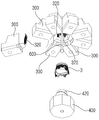
도 1은 실시예에 따른 금형장치를 나타낸 분해사시도,
도 2는 실시예에 따른 금형장치를 하부에서 본 분해사시도,
도 3은 실시예에 따른 금형장치를 나타낸 확대 사시도,
도 4는 실시예에 따른 금형장치를 나타낸 부분 확대도,
도 5는 실시예에 따른 금형장치를 확대한 분해사시도,
도 6은 실시예에 따른 금형장치를 나타낸 결합된 단면도.1 is an exploded perspective view showing a mold apparatus according to an embodiment,
Figure 2 is an exploded perspective view of the mold apparatus according to the embodiment seen from the bottom,
Figure 3 is an enlarged perspective view showing a mold apparatus according to the embodiment,
Figure 4 is a partial enlarged view showing a mold apparatus according to the embodiment,
Figure 5 is an exploded perspective view of an enlarged mold apparatus according to the embodiment,
Figure 6 is a combined cross-sectional view showing a mold apparatus according to the embodiment.
이하 바람직한 실시예를 첨부된 도면을 토대로 상세하게 설명하면 다음과 같다.Hereinafter, preferred embodiments will be described in detail with reference to the accompanying drawings.
하기에서 설명될 실시예는 본 발명이 속하는 기술분야에서 통상의 지식을 가진 자가 발명을 용이하게 실시할 수 있을 정도로 상세하게 설명하기 위한 것이며, 이로 인해 본 발명의 기술적인 사상 및 범주가 한정되는 것을 의미하지는 않는다.The embodiments to be described below are intended to be described in detail to the extent that one of ordinary skill in the art to which the present invention pertains can easily implement the invention, thereby limiting the technical spirit and scope of the present invention. Does not mean
또한, 도면에 도시된 구성요소의 크기나 형상 등은 설명의 명료성과 편의상 과장되게 도시될 수 있으며, 본 발명의 구성 및 작용을 고려하여 특별히 정의된 용어들은 사용자, 운용자의 의도 또는 관례에 따라 달라질 수 있고, 이러한 용어들에 대한 정의는 본 명세서 전반에 걸친 내용을 토대로 내려져야 함을 밝혀둔다. In addition, the size or shape of the components shown in the drawings may be exaggerated for clarity and convenience of description, and terms specifically defined in consideration of the configuration and operation of the present invention may vary depending on the intention or custom of the user or operator It should be noted that definitions of these terms should be made based on the contents throughout this specification.
첨부된 도면 중 도 1 및 도 2는 실시예에 따른 금형장치를 나타낸 분해사시도, 도 3은 실시예에 따른 금형장치를 나타낸 확대 사시도이다.1 and 2 of the accompanying drawings are exploded perspective views showing the mold apparatus according to the embodiment, and FIG. 3 is an enlarged perspective view showing the mold apparatus according to the embodiment.
도 1 내지 도 3에 도시된 바와 같이, 실시예에 따른 표면에 미세 문양이 형성된 조형물의 금형장치는, 원료를 투입하는 투입공이 형성되고, 하부면에 다수의 제1홈(120)과 제1돌부(110)가 원주방향으로 형성된 제1금형(100); 제1금형(100)에 대응되어 하부에 결합되고, 상부면에 다수의 제2홈(220)과 제2돌부(210)가 원주방향으로 형성된 제2금형(200); 제1금형(100)의 제1홈(120)과 제2금형(200)의 제2홈(220)에 결합되며 원주방향으로 배열되는 복수의 피스 몰드(300); 제1금형(100)과 제2금형(200)의 중심부에 결합되고, 상기 복수의 피스 몰드(300)의 일부분과 소정 간격으로 이격되어 성형지지부(420)가 형성된 코어부(400);를 포함한다. 1 to 3, the mold apparatus for a mold having a fine pattern formed on a surface according to an embodiment is formed with an input hole for inputting raw materials, and a plurality of
코어부(400)의 성형지지부(420)와 복수의 피스 몰드(300) 사이의 이격된 공간(이하 '캐비티(T)'라 함)에 원료가 주입되어 성형품(3)이 완성된다. Raw material is injected into the spaced space (hereinafter referred to as 'cavity (T)') between the
제1금형(100)은 중심부에 센터공이 형성되고, 상부에 천공되어 원료주입공(102)이 형성되고, 저면에는 원료가 이송되는 원료이송로(104)가 길이방향으로 형성되며, 상기 원료이송로(104)의 단부는 코어부(400)의 성형지지부(420)에 통하도록 형성된다. In the
제1금형(100)은 저면에 원주방향으로 복수의 제1돌부(110)가 등간격으로 돌출되게 방사상으로 형성되며, 각 제1돌부(110) 사이에는 제1홈(120)이 다수로 방사상으로 형성된다. The
제1돌부(110)는 육면체 형상으로 형성되되 내측면이 경사지도록 하여 제1경사면(111)이 형성된다. The
각 제1홈(120)에는 피스 몰드(300)가 각기 삽입되어 결합된다. A
또한 제1금형(100)에는 복수의 고정핀(180)이 각기 하방으로 관통 결합된다. 각 고정핀(180)은 피스 몰드(300)에 결합됨으로써 피스 몰드(300)가 정위치를 유지할 수 있도록 한다. In addition, a plurality of
제2금형(200)은 제1금형(100)의 하부에 맞물려 결합되는 것이며, 제1금형(100)의 제1돌부(110)가 결합되는 제2홈(220)이 방사상으로 형성되고, 각 제2홈(220) 사이에는 제2돌부(210)가 형성되어 제2돌부(210)와 제2홈(220)이 교호 형성된다. The
제2홈(220)에는 피스 몰드(300)가 결합된다. A
피스 몰드(300)는 다수개가 원주방향으로 조합되어 원형을 이루게 된다. The
도 3 내지 도 5에 도시된 바와 같이, 피스 몰드(300)는 일부분(제1,2금형(100)(200)의 외주연에 근접되는 부위)은 일정 깊이로 요입되어 단차부(330)가 형성되며, 타측에는 코어부(400)의 지지부(420)에 대응되어 조형물(3)의 표면을 형성하는 성형부(320)가 형성된다. As shown in FIGS. 3 to 5, the
단차부(330)는 제1돌부(110)의 제1경사면(111)에 대응되도록 제2경사면(332)이 형성된다. 따라서 제1금형(100)이 하방으로 가압하면 제1경사면(111)과 제2경사면(332) 간의 미는 작용으로 인해 피스 몰드(300)는 안쪽으로 모아지게 되고, 아울러 복수의 피스 몰드(300)가 모여서 원형 배열 형태를 견고하게 유지할 수 있게 된다. The
일 예에 따르면 피스 몰드(300)는 8개가 한조를 이루도록 하고, 성형품(3)의 외면을 360˚로 기준하였을때 1개의 피스 몰드(300)는 약 45˚에 대응하는 면적을 커버하게 된다. According to an example, eight piece molds 300 form a set, and when the outer surface of the molded
따라서 1개 피스 몰드(300)는 차지하는 면적이 협소하고, 다수의 피스 몰드(300)가 균등하게 조합되어 원형을 이루도록 한 것이므로, 다수의 피스 몰드(300)가 분리되면 각 피스 몰드(300)가 차지하는 면적이 작기때문에 성형품(3)의 외면에 손상을 입히지 않고 탈형작업이 깨끗하게 이루어질 수 있다. Therefore, since the area occupied by the one
피스 몰드(300)의 성형부(320)에는 돌기와 문양을 형성하도록 돌기홈(321)과 문양홈(323)이 형성된다.In the
다수의 피스 몰드(300)가 원형으로 조립되면 각 성형부(320)는 코어부(400)의 성형지지부(420)와 대응되어 소정의 간격으로 이격되어 배치된다. When a plurality of
이렇게 성형지지부(420)와 성형부(320) 간의 이격된 공간이 캐비티(T)가 된다(도 6 참조). In this way, the spaced apart between the
따라서 성형지지부(420)는 성형품(3)의 내면을 형성하게 되고, 성형부(320)는 성형품(3)의 외면을 형성하게 된다. Therefore, the
즉, 성형품(3)의 외면에 원하는 형상을 구현해낼 수 있도록 성형부(320)의 돌기홈과 문양홈을 정교하게 양각 또는 음각으로 형성함으로써 성형품(3)의 외면에 특정 형상의 돌기와 문양이 형성될 수 있다. That is, by forming the projection grooves and the pattern grooves of the
한편 코어부(400)는 제2금형(200)의 중심홈(205)에 끼움결합되는 베드(410)와, 상기 베드(410)의 상부에 형성되어 상기 복수의 피스 몰드(300)의 성형부(320)와 소정 간격으로 이격되어 성형지지부(420)가 형성된다. On the other hand, the
제2금형(200)의 중심홈(205)은 육각형으로 형성되고, 이에 꼭맞게 결합되도록 베드(410)도 육각형으로 형성되며, 성형지지부(420)는 상부로 갈수록 직경이 작아져 원뿔 형상으로 형성된다. The
성형지지부(420)의 형상은 하나의 예시일 뿐이며 반드시 이에 한정될 필요는 없다. The shape of the
한편 제1금형(100)과 제2금형(200)의 센터공을 관통하여 결합되는 연결부재(600)가 포함된다. On the other hand, the
연결부재(600)는 제1금형(100), 제2금형(200) 및 코어부(400)의 중심을 관통하여 결합되는 볼트이며, 제1금형(100), 제2금형(200), 코어부(400)가 견고하게 일체된 상태로 유지될 수 있도록 결합력을 제공하게 된다. The connecting
이와 같이 구성된 실시예의 작용을 설명한다. The operation of the embodiment configured as described above will be described.
제1금형(100)과 제2금형(200)을 상,하부에 각기 배치하고, 그 사이에 복수의 피스 몰드(300)를 결합한다.The
복수의 피스 몰드(300) 각각은 제1홈부(120) 및 제2홈부(220)에 결합된다. 제1금형(100)에는 복수의 고정핀(180)이 각기 하방으로 관통 결합되고 각 고정핀(180)이 대응되는 피스 몰드(300)에 결합됨으로써 피스 몰드(300)가 분산되지 않고 정위치를 유지할 수 있게 된다. Each of the plurality of
이후 제2금형(200)의 중심부에 코어부(400)를 결합한다.Thereafter, the
이후 제2금형(200), 코어부(400), 제1금형(100)의 중심을 관통하여 연결부재(600)를 결합하고, 연결부재(600)를 조여서 제1,2금형(100,200)과 코어부(400)가 견고하게 일체된 상태가 되도록 한다. Subsequently, the
이후 원료주입공(102)으로 원료를 주입하면 원료이송로(104)를 따라 캐비티(T)로 주입된다. Subsequently, when the raw material is injected into the raw
이후 일정 시간 경과 후 연결부재(600)를 분리하고, 제1금형(100)을 상부로 분리하고, 각 피스 몰드(300)를 분리하면 성형품(3)이 코어부(400)에 형성된 상태가 된다. Then, after a certain period of time, the connecting
이후 코어부(400) 및 제2금형(200)을 분리하여 성형품을 취출한다. Thereafter, the
따라서 성형품(3)은 성형부(320)에 형성된 돌기와 문양이 표면에 형성될 수 있으므로 미세하고 정교한 돌기와 문양을 각 피스 몰드(300)를 통해 정교하게 표출해낼 수 있는 것이다. Therefore, the molded
비록 바람직한 실시예와 관련하여 설명되어졌지만, 발명의 요지와 범위로부터 벗어남이 없이 다양한 수정 및 변형이 가능한 것은 당업자라면 용이하게 인식할 수 있을 것이며, 이러한 변경 및 수정은 모두 첨부된 청구의 범위에 속함은 자명하다.Although described in connection with the preferred embodiment, various modifications and variations can be readily recognized by those skilled in the art without departing from the spirit and scope of the invention, and all such changes and modifications are within the scope of the appended claims. Is self-explanatory.
100 ; 제1금형 200 : 제2금형
300 : 피스 몰드 400 : 코어부
3 : 조형물 420 : 지지부 100; 1st mold 200: 2nd mold
300: piece mold 400: core portion
3: Sculpture 420: Support
Claims (10)
상기 제1금형에 대응되어 하부에 결합되고, 상부면에 다수의 제2홈과 제2돌부가 원주방향으로 형성된 제2금형;
상기 제1금형의 제1홈과 상기 제2금형의 제2홈에 결합되는 복수의 피스 몰드;
상기 제1금형과 제2금형의 중심부에 결합되고, 상기 복수의 피스 몰드의 일부분과 이격되어 성형지지부가 형성된 코어부;를 포함하고,
상기 복수의 피스 몰드 각각은,
상기 코어부의 지지부에 대응되어 조형물의 표면을 형성하는 성형부가 형성되고, 상기 성형부에는 돌기와 문양을 형성하도록 돌기홈과 문양홈이 형성되고,
상기 제1금형은
중심부에 형성된 센터공과, 상부에 형성된 원료주입공과, 저면에 길이방향으로 형성되어 원료가 이송되는 원료이송로를 포함하고,
상기 원료이송로의 단부는 코어부의 성형지지부에 통하도록 형성되며,
상기 제1금형은 저면에 원주방향으로 복수의 제1돌부가 등간격으로 돌출되게 방사상으로 형성되며, 각 제1돌부 사이에 제1홈이 다수로 방사상으로 형성되고,
상기 제1돌부는 육면체 형상으로 형성되되 내측면이 경사지도록 하여 제1경사면이 형성되며,
상기 복수의 피스 몰드 각각은, 일부분은 요입되어 단차부가 형성되며, 타측에는 코어부의 지지부에 대응되어 조형물의 표면을 형성하는 성형부가 형성되며,
상기 단차부는 제1돌부의 제1경사면에 대응되도록 제2경사면이 형성된 것을 특징으로 하는 표면에 미세 문양이 형성된 조형물의 금형장치. A first mold in which an input hole for inputting raw materials is formed, and a plurality of first grooves and first protrusions are formed in a circumferential direction on a lower surface;
A second mold coupled to the lower portion corresponding to the first mold, and having a plurality of second grooves and second protrusions formed in a circumferential direction on an upper surface;
A plurality of piece molds coupled to the first groove of the first mold and the second groove of the second mold;
It includes; a core portion coupled to the center of the first mold and the second mold, spaced apart from a part of the plurality of molds, and formed with a molding support;
Each of the plurality of piece molds,
A molding part is formed to form a surface of the molded object in correspondence with the support part of the core part, and a projection groove and a pattern groove are formed in the molding part to form a protrusion and a pattern,
The first mold
It includes a center hole formed in the center, a raw material injection hole formed in the upper portion, and a raw material transfer path formed in the longitudinal direction on the bottom surface to transfer the raw material,
The end of the raw material transport path is formed to pass through the forming support of the core portion,
The first mold is radially formed such that a plurality of first protrusions protrude at equal intervals in the circumferential direction on the bottom surface, and a plurality of first grooves are formed radially between each first protrusion,
The first protrusion is formed in a hexahedral shape, but a first inclined surface is formed by inclining the inner surface.
Each of the plurality of piece molds, a part is recessed to form a step portion, and the other side is formed with a molding portion corresponding to the support portion of the core portion to form the surface of the molding,
The step portion is a mold apparatus of a molded pattern is formed on the surface, characterized in that the second inclined surface is formed to correspond to the first inclined surface of the first projection.
상기 제1금형에는 복수의 고정핀이 관통 결합되고,
각 고정핀은 피스 몰드에 결합되는 것을 특징으로 하는 표면에 미세 문양이 형성된 조형물의 금형장치. According to claim 1,
A plurality of fixing pins are coupled to the first mold,
Each fixing pin is a mold device of a molded object with a fine pattern formed on the surface, which is coupled to a piece mold.
상기 성형부는 코어부의 성형지지부와 이격되고,
상기 성형지지부와 성형부 간의 이격 공간인 캐비티가 형성되며,
상기 성형지지부는 성형품의 내면을 형성하게 되고, 성형부는 성형품의 외면을 형성하는 것을 특징으로 하는 표면에 미세 문양이 형성된 조형물의 금형장치. According to claim 1,
The molding portion is spaced apart from the molding support portion of the core portion,
A cavity that is a separation space between the molding support portion and the molding portion is formed,
The molding support portion forms an inner surface of the molded article, and the molded portion molds a molded article having a fine pattern formed on the surface, which forms an outer surface of the molded article.
상기 코어부는
제2금형의 중심홈에 끼움결합되는 베드와, 상기 베드의 상부에 형성되어 상기 복수의 피스 몰드의 성형부와 이격되어 성형지지부가 형성된 것을 특징으로 하는 표면에 미세 문양이 형성된 조형물의 금형장치. According to claim 1,
The core portion
A molding device having a fine pattern on the surface, characterized in that the bed is fitted into the center groove of the second mold and is formed on an upper part of the bed to be spaced apart from the molding parts of the plurality of piece molds to form a molding support.
상기 제1금형과 제2금형을 결합하는 연결부재가 포함되는 것을 특징으로 하는 표면에 미세 문양이 형성된 조형물의 금형장치. According to claim 1,
A mold device for a mold having a fine pattern formed on a surface, comprising a connecting member for coupling the first mold and the second mold.
Applications Claiming Priority (2)
| Application Number | Priority Date | Filing Date | Title |
|---|---|---|---|
| KR1020180050896 | 2018-05-02 | ||
| KR20180050896 | 2018-05-02 |
Publications (2)
| Publication Number | Publication Date |
|---|---|
| KR20190126694A KR20190126694A (en) | 2019-11-12 |
| KR102106494B1 true KR102106494B1 (en) | 2020-05-04 |
Family
ID=68577595
Family Applications (1)
| Application Number | Title | Priority Date | Filing Date |
|---|---|---|---|
| KR1020180077716A Active KR102106494B1 (en) | 2018-05-02 | 2018-07-04 | Molding device of molding with fine pattern on the surface |
Country Status (1)
| Country | Link |
|---|---|
| KR (1) | KR102106494B1 (en) |
Cited By (1)
| Publication number | Priority date | Publication date | Assignee | Title |
|---|---|---|---|---|
| KR102801984B1 (en) * | 2024-08-16 | 2025-04-30 | 주식회사 현우엠텍 | Mold device for injection molding of columnar parts with spiral grooves |
Families Citing this family (1)
| Publication number | Priority date | Publication date | Assignee | Title |
|---|---|---|---|---|
| KR102593170B1 (en) * | 2021-12-03 | 2023-10-25 | (주)진양오일씰 | Manufacturing method of exterior cover of electronic device |
Citations (2)
| Publication number | Priority date | Publication date | Assignee | Title |
|---|---|---|---|---|
| KR100844257B1 (en) | 2007-06-11 | 2008-07-07 | 정지영 | Short golf ball manufacturing method |
| KR101203985B1 (en) | 2011-07-19 | 2012-11-22 | 박대규 | Mold |
Family Cites Families (4)
| Publication number | Priority date | Publication date | Assignee | Title |
|---|---|---|---|---|
| KR20100131191A (en) * | 2009-06-05 | 2010-12-15 | (주)성산정공 | Molding apparatus for forming acupressure projections of spherical surface |
| KR101372619B1 (en) | 2012-08-19 | 2014-03-11 | 조형진 | Multi-split mold and molding |
| KR101519949B1 (en) * | 2013-11-05 | 2015-05-14 | 이중재 | Injection mold for forming product having undercut |
| KR101857959B1 (en) * | 2016-09-22 | 2018-05-16 | 현대성우메탈 주식회사 | Mold for Manufacturing Rim and Manufacturing Method of Rim Using the Same |
-
2018
- 2018-07-04 KR KR1020180077716A patent/KR102106494B1/en active Active
Patent Citations (2)
| Publication number | Priority date | Publication date | Assignee | Title |
|---|---|---|---|---|
| KR100844257B1 (en) | 2007-06-11 | 2008-07-07 | 정지영 | Short golf ball manufacturing method |
| KR101203985B1 (en) | 2011-07-19 | 2012-11-22 | 박대규 | Mold |
Cited By (1)
| Publication number | Priority date | Publication date | Assignee | Title |
|---|---|---|---|---|
| KR102801984B1 (en) * | 2024-08-16 | 2025-04-30 | 주식회사 현우엠텍 | Mold device for injection molding of columnar parts with spiral grooves |
Also Published As
| Publication number | Publication date |
|---|---|
| KR20190126694A (en) | 2019-11-12 |
Similar Documents
| Publication | Publication Date | Title |
|---|---|---|
| JP2008514364A5 (en) | ||
| KR102106494B1 (en) | Molding device of molding with fine pattern on the surface | |
| US3687591A (en) | An injection molding apparatus having ejector pins with oriented shaping surfaces for product removal | |
| KR20160000996U (en) | Mold for injection molding | |
| US2087470A (en) | Method of making buttons from plastic material | |
| US20080289356A1 (en) | Apparatus for Producing Ice Vessel | |
| JP7296323B2 (en) | METHOD FOR MANUFACTURING RESIN CONTAINER PARTS, MOLD UNIT AND BLOW MOLDING MACHINE INCLUDING THE SAME | |
| US20090224135A1 (en) | Mold unit with replaceable mold core holder | |
| BR0108073A (en) | Apparatus for manufacturing plastic articles provided with external recesses | |
| CN207724744U (en) | A kind of molding die of grid mask | |
| KR101355755B1 (en) | Carbide ceramic molding jig molds for the production of isolated and integrated | |
| KR100741657B1 (en) | Injection Mold | |
| KR101177431B1 (en) | Bidirectional Injection Mold | |
| US20030047299A1 (en) | Investment molding flask assembly | |
| KR200486819Y1 (en) | Mold frame structure | |
| US656392A (en) | Dish-mold. | |
| CN205616773U (en) | A mold structure for producing glass products | |
| KR20210115787A (en) | Method for manufacturing ornaments in the form of an empty net | |
| TWI588005B (en) | Hand tools multi-color handle manufacturing methods | |
| TW201716222A (en) | Method and mold for manufacturing optical lens and product thereof which may sustain force evenly, is difficult to be deformed, and has high yield rate | |
| US447556A (en) | George w | |
| KR100512704B1 (en) | Method for manufactuing braille block of the blind and braille block manufactured the same | |
| CN204585690U (en) | There is the plastic cement picture frame shaped device of artificial leather decorative cover | |
| US447555A (en) | George w | |
| CN206356553U (en) | Die-casting molds for transmission parts |
Legal Events
| Date | Code | Title | Description |
|---|---|---|---|
| A201 | Request for examination | ||
| PA0109 | Patent application |
Patent event code: PA01091R01D Comment text: Patent Application Patent event date: 20180704 |
|
| PA0201 | Request for examination | ||
| PG1501 | Laying open of application | ||
| E902 | Notification of reason for refusal | ||
| PE0902 | Notice of grounds for rejection |
Comment text: Notification of reason for refusal Patent event date: 20191120 Patent event code: PE09021S01D |
|
| E701 | Decision to grant or registration of patent right | ||
| PE0701 | Decision of registration |
Patent event code: PE07011S01D Comment text: Decision to Grant Registration Patent event date: 20200416 |
|
| PR0701 | Registration of establishment |
Comment text: Registration of Establishment Patent event date: 20200424 Patent event code: PR07011E01D |
|
| PR1002 | Payment of registration fee |
Payment date: 20200427 End annual number: 3 Start annual number: 1 |
|
| PG1601 | Publication of registration | ||
| PR1001 | Payment of annual fee |
Payment date: 20230410 Start annual number: 4 End annual number: 4 |
|
| PR1001 | Payment of annual fee |
Payment date: 20240430 Start annual number: 5 End annual number: 5 |
|
| PR1001 | Payment of annual fee |
Payment date: 20250211 Start annual number: 6 End annual number: 6 |