KR102062053B1 - Radio frequency id tag having structure for inlay spacing - Google Patents
Radio frequency id tag having structure for inlay spacing Download PDFInfo
- Publication number
- KR102062053B1 KR102062053B1 KR1020147019551A KR20147019551A KR102062053B1 KR 102062053 B1 KR102062053 B1 KR 102062053B1 KR 1020147019551 A KR1020147019551 A KR 1020147019551A KR 20147019551 A KR20147019551 A KR 20147019551A KR 102062053 B1 KR102062053 B1 KR 102062053B1
- Authority
- KR
- South Korea
- Prior art keywords
- housing portion
- rfid
- shelf
- protrusions
- radio frequency
- Prior art date
- Legal status (The legal status is an assumption and is not a legal conclusion. Google has not performed a legal analysis and makes no representation as to the accuracy of the status listed.)
- Active
Links
Images


Classifications
-
- G—PHYSICS
- G06—COMPUTING OR CALCULATING; COUNTING
- G06K—GRAPHICAL DATA READING; PRESENTATION OF DATA; RECORD CARRIERS; HANDLING RECORD CARRIERS
- G06K19/00—Record carriers for use with machines and with at least a part designed to carry digital markings
- G06K19/04—Record carriers for use with machines and with at least a part designed to carry digital markings characterised by the shape
- G06K19/041—Constructional details
- G06K19/047—Constructional details the record carrier being shaped as a coin or a gambling token
-
- E—FIXED CONSTRUCTIONS
- E05—LOCKS; KEYS; WINDOW OR DOOR FITTINGS; SAFES
- E05B—LOCKS; ACCESSORIES THEREFOR; HANDCUFFS
- E05B73/00—Devices for locking portable objects against unauthorised removal; Miscellaneous locking devices
- E05B73/0017—Anti-theft devices, e.g. tags or monitors, fixed to articles, e.g. clothes, and to be removed at the check-out of shops
-
- G—PHYSICS
- G06—COMPUTING OR CALCULATING; COUNTING
- G06K—GRAPHICAL DATA READING; PRESENTATION OF DATA; RECORD CARRIERS; HANDLING RECORD CARRIERS
- G06K19/00—Record carriers for use with machines and with at least a part designed to carry digital markings
- G06K19/06—Record carriers for use with machines and with at least a part designed to carry digital markings characterised by the kind of the digital marking, e.g. shape, nature, code
- G06K19/067—Record carriers with conductive marks, printed circuits or semiconductor circuit elements, e.g. credit or identity cards also with resonating or responding marks without active components
- G06K19/07—Record carriers with conductive marks, printed circuits or semiconductor circuit elements, e.g. credit or identity cards also with resonating or responding marks without active components with integrated circuit chips
- G06K19/077—Constructional details, e.g. mounting of circuits in the carrier
- G06K19/07749—Constructional details, e.g. mounting of circuits in the carrier the record carrier being capable of non-contact communication, e.g. constructional details of the antenna of a non-contact smart card
-
- G—PHYSICS
- G08—SIGNALLING
- G08B—SIGNALLING SYSTEMS, e.g. PERSONAL CALLING SYSTEMS; ORDER TELEGRAPHS; ALARM SYSTEMS
- G08B13/00—Burglar, theft or intruder alarms
- G08B13/22—Electrical actuation
- G08B13/24—Electrical actuation by interference with electromagnetic field distribution
- G08B13/2402—Electronic Article Surveillance [EAS], i.e. systems using tags for detecting removal of a tagged item from a secure area, e.g. tags for detecting shoplifting
- G08B13/2405—Electronic Article Surveillance [EAS], i.e. systems using tags for detecting removal of a tagged item from a secure area, e.g. tags for detecting shoplifting characterised by the tag technology used
- G08B13/2414—Electronic Article Surveillance [EAS], i.e. systems using tags for detecting removal of a tagged item from a secure area, e.g. tags for detecting shoplifting characterised by the tag technology used using inductive tags
- G08B13/2417—Electronic Article Surveillance [EAS], i.e. systems using tags for detecting removal of a tagged item from a secure area, e.g. tags for detecting shoplifting characterised by the tag technology used using inductive tags having a radio frequency identification chip
-
- G—PHYSICS
- G08—SIGNALLING
- G08B—SIGNALLING SYSTEMS, e.g. PERSONAL CALLING SYSTEMS; ORDER TELEGRAPHS; ALARM SYSTEMS
- G08B13/00—Burglar, theft or intruder alarms
- G08B13/22—Electrical actuation
- G08B13/24—Electrical actuation by interference with electromagnetic field distribution
- G08B13/2402—Electronic Article Surveillance [EAS], i.e. systems using tags for detecting removal of a tagged item from a secure area, e.g. tags for detecting shoplifting
- G08B13/2428—Tag details
- G08B13/2434—Tag housing and attachment details
-
- Y—GENERAL TAGGING OF NEW TECHNOLOGICAL DEVELOPMENTS; GENERAL TAGGING OF CROSS-SECTIONAL TECHNOLOGIES SPANNING OVER SEVERAL SECTIONS OF THE IPC; TECHNICAL SUBJECTS COVERED BY FORMER USPC CROSS-REFERENCE ART COLLECTIONS [XRACs] AND DIGESTS
- Y10—TECHNICAL SUBJECTS COVERED BY FORMER USPC
- Y10T—TECHNICAL SUBJECTS COVERED BY FORMER US CLASSIFICATION
- Y10T29/00—Metal working
- Y10T29/49—Method of mechanical manufacture
- Y10T29/49826—Assembling or joining
Landscapes
- Engineering & Computer Science (AREA)
- Physics & Mathematics (AREA)
- General Physics & Mathematics (AREA)
- Theoretical Computer Science (AREA)
- Computer Hardware Design (AREA)
- Microelectronics & Electronic Packaging (AREA)
- Burglar Alarm Systems (AREA)
- Support Of Aerials (AREA)
Abstract
무선 주파수 식별(RFID) 안전 시스템 태그가 제공된다. 상기 태그는 RFID 요소 및 제 1 하우징 부분을 포함한다. 제 1 하우징 부분은 내부 및 개구를 형성한다. 상기 제 1 하우징 부분의 내부는 내측 주변부 및 상기 내측 주변부의 적어도 일 부분을 중심으로 배치되는 선반을 포함한다. 상기 제 1 하우징 부분의 내부는 또한 복수의 돌기들을 포함하며 상기 복수의 돌기들은 상기 선반으로부터 상기 개구를 향하여 외측으로 연장한다. RFID 요소는 상기 복수의 돌기들 상에 적어도 부분적으로 배치된다.A radio frequency identification (RFID) safety system tag is provided. The tag includes an RFID element and a first housing portion. The first housing portion defines an interior and an opening. The interior of the first housing portion includes an inner perimeter and a shelf disposed about at least a portion of the inner perimeter. The interior of the first housing portion also includes a plurality of protrusions which extend outwardly from the shelf towards the opening. An RFID element is at least partially disposed on the plurality of protrusions.
Description
본 발명은 무선 주파수 식별(RFID) 안전 태크들의 분야에 관한 것이며, 특히 내부에 포함되는 RFID 인레이들의 성능에 대한 태그 하우징들의 효과들을 최소화하는 것에 관한 것이다.
The present invention relates to the field of radio frequency identification (RFID) safety tags, and in particular to minimizing the effects of tag housings on the performance of RFID inlays contained therein.
무선 통신 태그들은 다른 환경들 중에서도, 소매점 및/또는 도매점 환경들에서 종종 발견된다. 무선 통신 태그들은 패키지들, 컨테이너들, 재고 아이템들 및 재고 물품들, 자산 관리 및/또는 안전 목적들과 같은 아이템들을 추적하고 식별하는데 사용될 수 있다.
Wireless communication tags are often found in retail and / or wholesaler environments, among other environments. Wireless communication tags can be used to track and identify items such as packages, containers, inventory items and inventory items, asset management and / or safety purposes.
한 형태의 무선 통신 태그는 무선 주파수 식별(RFID) 태그이다. RFID 태그는 저장된 정보, 예를 들어 무선 주파수(RF) 신호들을 사용하는 아이템 관련 정보를 전송한다. 특히, RFID 태그는 안테나 및 그 위에 배치되는 집적 회로(IC) 칩을 갖춘 인레이(inlay)를 포함할 수 있으며, 여기서 IC 칩은 안테나에 연결된다. IC 칩은 프로그램된 정보, 예를 들어 아이템과 관련된 정보를 저장한다. RFID 리더로부터의 호출 신호(interrogation signal)의 수신에 응답하여 IC 칩은 프로그램된 정보를 안테나에 의해 전송되는 대응 전자기 신호로 변환한다. RFID 태그는 특정 주파수 또는 좁은 범위의 주파수들에서 호출 신호를 수신하도록 튜닝된다.
One type of wireless communication tag is a radio frequency identification (RFID) tag. The RFID tag transmits stored information, for example item related information using radio frequency (RF) signals. In particular, the RFID tag may comprise an inlay with an antenna and an integrated circuit (IC) chip disposed thereon, where the IC chip is connected to the antenna. The IC chip stores programmed information, for example information related to the item. In response to receiving an interrogation signal from the RFID reader, the IC chip converts the programmed information into a corresponding electromagnetic signal transmitted by the antenna. The RFID tag is tuned to receive the call signal at a specific frequency or a narrow range of frequencies.
그러나, RFID 태그의 성능은 다양한 요인들에 따라 변화될 수 있다. 하나의 요인은 인레이와 RFID 태그의 플라스틱 하우징 사이의 상호 작용을 포함한다. 예를 들어, 하우징과 접촉함이 없이 하우징의 외측에 위치될 때 안테나는 호출 신호에 대한 특정 반응을 나타낼 수 있다. 안테나를 갖춘 기판을 RFID 태그의 하우징 내에 놓는 것은 상당히 적은 호출 신호가 RFID 태그에 의해 포착되도록, 즉 RFID 태그가 호출 신호에 반응하지 않을 수 있거나 빈약하게 반응하도록 안테나의 주파수 응답을 변경할 수 있다. 기판과 하우징 사이의 상호 작용 또는 접촉은 안테나의 이조(detuning)를 초래한다. 게다가, RFID 태그 내의 기판의 운동은 안테나의 튜닝 주파수를 시프팅하는 것과 같이 기판과 하우징 사이의 상호 작용을 더욱 변화시킬 수 있다. 예를 들어, RFID 태그는 가계 또는 도매점 주위에서 이동되는 물품에 부착될 수 있어서, 안테나를 갖춘 기판이 기판과 하우징 사이의 상호 작용을 변화시키는 RFID 태그 내부의 주위에서 시프팅된다. 이조된 RFID 태그는 안테나가 더 이상 호출 신호로 튜닝되지 않기 때문에 호출 신호를 수용하지 못할 수 있다. 환언하면, RFID 리더는 RFID 태그를 판독 또는 호출할 수 없으거나 판독 성능이 저하된다.However, the performance of an RFID tag can vary depending on various factors. One factor involves the interaction between the inlay and the plastic housing of the RFID tag. For example, the antenna may exhibit a specific response to the call signal when positioned outside of the housing without contact with the housing. Placing the substrate with the antenna in the housing of the RFID tag can alter the frequency response of the antenna such that significantly less call signals are captured by the RFID tag, that is, the RFID tag may or may not respond to the call signal poorly. Interaction or contact between the substrate and the housing results in detuning of the antenna. In addition, the movement of the substrate in the RFID tag can further change the interaction between the substrate and the housing, such as shifting the tuning frequency of the antenna. For example, an RFID tag may be attached to an article that is moved around a household or wholesaler, such that a substrate with an antenna is shifted around the inside of the RFID tag that changes the interaction between the substrate and the housing. The faked RFID tag may not accept the call signal because the antenna is no longer tuned to the call signal. In other words, the RFID reader cannot read or call the RFID tag or the read performance is degraded.
RFID 태그들의 성능에 영향을 끼치는 다른 요인은 하우징 재료이다. 예를 들어, 신호 또는 안테나 이조의 손실은 플라스틱 하우징 재료들의 손실 특징들에 의해 유발될 수 있다. 게다가, 상이한 제작들에 사용된 하우징 재료들의 편차들이 또한 튜닝 편차들을 초래할 수 있다. 환언하면, 하우징 재료 자체가 RFID 태그를 이조시킬 수 있다.
Another factor affecting the performance of RFID tags is the housing material. For example, loss of signal or antenna duplex can be caused by loss characteristics of plastic housing materials. In addition, variations in housing materials used in different fabrications can also result in tuning variations. In other words, the housing material itself can migrate the RFID tag.
여러 해결책들이 RFID 태그 성능을 유지하는데 도움을 주기 위해 제안되었다. 하나의 해결책은 RFID 태그 내에서의 기판의 운동을 억제하는 것이다. 예를 들어, 기판은 하우징에 접착될 수 있거나 하우징은 하우징에 대해 기판을 확실하게 가압하는 클립-형 구조물로 구성될 수 있다. 이러한 해결책이 기판의 운동을 감소시키지만, 기판과 하우징 사이의 상호 작용은 아마도 증가된다. RFID 태그의 튜닝 주파수가 운동으로 인해 변하지 않을 수 있지만, 기판과 하우징 사이의 증가된 상호 작용은 안테나를 이조시킬 수 있으며, 즉 RFID 태그는 아마도 이조상태로 유지될 것이다.
Several solutions have been proposed to help maintain RFID tag performance. One solution is to suppress the movement of the substrate within the RFID tag. For example, the substrate may be adhered to the housing or the housing may consist of a clip-like structure that reliably presses the substrate against the housing. While this solution reduces the motion of the substrate, the interaction between the substrate and the housing is probably increased. Although the tuning frequency of the RFID tag may not change due to motion, the increased interaction between the substrate and the housing may double the antenna, ie the RFID tag will probably remain duplex.
다른 해결책은 하우징 크기를 감소시킴으로써 안테나와 하우징 사이의 상호 작용을 감소시키는 것을 포함한다. 특히, 하우징의 크기는 안테나가 하우징의 인레이 지지 구조물로부터 떨어져 위치될 수 있도록 증가된다. 그러나, 이러한 해결책은 제작 비용을 증가시키고 태그가 부착되는 아이템의 미적 매력을 훼손하는 것과 같은 태그의 크기를 불리하게 증가시킨다.
Another solution includes reducing the interaction between the antenna and the housing by reducing the housing size. In particular, the size of the housing is increased so that the antenna can be positioned away from the inlay support structure of the housing. However, this solution increases the production cost and disadvantageously increases the size of the tag, such as undermining the aesthetic appeal of the item to which the tag is attached.
본 발명은 개선된 안전 태그 하우징을 위한 시스템, 장치 및 방법을 유리하게 제공한다.
The present invention advantageously provides a system, apparatus and method for an improved safety tag housing.
일 실시예에 따라서, 무선 주파수 식별(RFID) 안전 시스템 태그가 제공된다. 태그는 RFID 요소 및 제 1 하우징 부분을 포함한다. 제 1 하우징 부분은 내부 및 개구를 한정한다. 제 1 하우징 부분의 내부는 내측 주변부 및 내측 주변부의 적어도 일부분의 주위에 배치되는 선반(shelf)를 포함한다. 제 1 하우징 부분의 내부는 또한, 복수의 돌기들을 포함하며, 그 내부에서 복수의 돌기들이 선반으로부터 개구를 향해 외측으로 연장한다. RFID 요소는 복수의 돌기들 상에 적어도 부분적으로 배치된다.According to one embodiment, a radio frequency identification (RFID) security system tag is provided. The tag includes an RFID element and a first housing portion. The first housing portion defines an interior and an opening. The interior of the first housing portion includes a shelf disposed around the inner perimeter and at least a portion of the inner perimeter. The interior of the first housing portion also includes a plurality of protrusions, in which the plurality of protrusions extend outwardly from the shelf towards the opening. The RFID element is at least partially disposed on the plurality of protrusions.
다른 실시예에 따라서, 안전 시스템 태그가 제공된다. 그 태그는 내부 및 개구를 한정하는 제 1 하우징 부분을 포함한다. 제 1 하우징 부분의 내부는 내측 주변부 및 내측 주변부의 적어도 일부분 주위에 배치되는 선반을 포함한다. 제 1 하우징 부분의 내부는 또한, 복수의 돌기들을 포함하며, 그 내부에서 복수의 돌기들이 선반으로부터 개구를 향해 외측으로 연장한다.According to another embodiment, a safety system tag is provided. The tag includes a first housing portion defining an interior and an opening. The interior of the first housing portion includes an inner periphery and a shelf disposed around at least a portion of the inner periphery. The interior of the first housing portion also includes a plurality of protrusions, in which the plurality of protrusions extend outwardly from the shelf towards the opening.
다른 실시예에 따라서, 방법이 제공된다. 안전 태그는 물품에 부착된다. 안전 태그는 무선 주파수 식별(RFID) 요소 및 하우징 부분을 포함한다. 하우징 부분은 내부 및 개구를 한정한다. 하우징 부분의 내부는 내측 주변부 및 내측 주변부의 적어도 일부분 주위에 배치되는 선반을 포함한다. 하우징 부분의 내부는 복수의 돌기들을 포함하며, 그 내부에서 복수의 돌기들이 선반으로부터 개구를 향해 외측으로 연장한다. RFID 요소는 복수의 돌기들 상에 적어도 부분적으로 배치된다.According to another embodiment, a method is provided. The safety tag is attached to the article. The safety tag includes a radio frequency identification (RFID) element and a housing portion. The housing portion defines the interior and the opening. The interior of the housing portion includes a shelf disposed around the inner perimeter and at least a portion of the inner perimeter. The interior of the housing portion includes a plurality of protrusions, in which the plurality of protrusions extend outwardly from the shelf towards the opening. The RFID element is at least partially disposed on the plurality of protrusions.
본 발명의 보다 완벽한 이해, 그리고 그의 수반되는 이점들 및 특징들은 첨부 도면들과 함께 고려될 때 하기 상세한 설명을 참조함으로써 보다 용이하게 이해될 것이다.
도 1은 본 발명에 따라 구성된 예시적 안전 태그 시스템의 측면도를 예시하며,
도 2는 본 발명에 따라 구성된 안전 태그 시스템의 분해도를 예시하며,
도 3은 본 발명에 따라 구성된 안전 태그의 제 1 하우징 부분의 사시도를 예시하며,
도 4는 본 발명에 따라 구성된 인레이의 평면도를 예시하며,
도 5는 본 발명에 따라 구성된 안전 태그의 제 2 하우징 부분의 사시도를 예시하며,
도 6은 본 발명에 따라 구성된 안전 태그 시스템의 일 부분의 사시도를 예시하며,
도 7은 본 발명에 따라 구성된 안전 태그 시스템의 일 부분의 횡단면도를 예시하며,
도 8은 본 발명에 따라 구성된 안전 태그 시스템의 일 부분의 다른 횡단면도를 예시하며,
도 9는 본 발명에 따라 구성된 안전 태그 시스템의 다른 실시예의 일 부분의 횡단면도를 예시하며,
도 10은 본 발명의 원리들에 따라 구성된 돌기의 측면도를 예시하며,
도 11은 본 발명의 원리들에 따라 구성된 다른 돌기의 측면도를 예시하며,
도 12는 본 발명의 원리들에 따라 구성된 또 다른 돌기의 측면도를 예시하며,
도 13은 계속해서(still) 본 발명의 원리들에 따라 구성된 또 다른 돌기의 측면도를 예시한다.A more complete understanding of the invention, and its accompanying advantages and features, will be more readily understood by reference to the following detailed description when considered in conjunction with the accompanying drawings.
1 illustrates a side view of an exemplary safety tag system constructed in accordance with the present invention,
2 illustrates an exploded view of a safety tag system constructed in accordance with the present invention,
3 illustrates a perspective view of a first housing portion of a safety tag constructed in accordance with the present invention,
4 illustrates a top view of an inlay constructed in accordance with the present invention,
5 illustrates a perspective view of a second housing portion of a safety tag constructed in accordance with the present invention,
6 illustrates a perspective view of a portion of a safety tag system constructed in accordance with the present invention,
7 illustrates a cross-sectional view of a portion of a safety tag system constructed in accordance with the present invention,
8 illustrates another cross-sectional view of a portion of a safety tag system constructed in accordance with the present invention,
9 illustrates a cross-sectional view of a portion of another embodiment of a safety tag system constructed in accordance with the present invention,
10 illustrates a side view of a protrusion constructed in accordance with the principles of the present invention,
11 illustrates a side view of another protrusion constructed in accordance with the principles of the present invention,
12 illustrates a side view of another protrusion constructed in accordance with the principles of the present invention,
Figure 13 still illustrates a side view of another projection constructed in accordance with the principles of the present invention.
본 발명은 무선 주파수 식별(RFID: radio frequency identification) 태그들을 위한 시스템, 장치 및 방법을 유리하게 제공한다. 이에 따라, 시스템, 장치 및 방법 구성요소들이 도면들에서 종래의 부호들에 의해서 적절한 곳으로 나타내어지며, 본 발명의 실시예들을 이해시키는데 부속되는 단지 이러한 특징적 상세들을 도시하여 본원의 상세한 설명의 이점을 갖는 당업자에게 용이하게 명확할 수 있는 상세들에 의해 명세서를 모호하지 않게 한다.
The present invention advantageously provides a system, apparatus and method for radio frequency identification (RFID) tags. Accordingly, system, apparatus, and method components are shown where appropriate by conventional symbols in the drawings, and only show such characteristic details as are attached to understanding embodiments of the present invention to take advantage of the description herein. The specification is not to be obscured by details that may be readily apparent to those skilled in the art.
본원에 사용된 바와 같이, 관련 용어들, 예컨대 "제 1" 및 "제 2", "상부" 및 "저부" 등은 하나의 단일체(entity) 또는 요소를 다른 단일체 또는 요소와, 이러한 단일체들 또는 요소들 사이의 임의의 물리적 또는 논리적 관계 또는 순서를 반드시 요구하거나 함축하지 않으면서, 구별하기 위해서 단독으로 사용될 수 있다.
As used herein, related terms such as “first” and “second”, “top” and “bottom”, etc., refer to one entity or element with another entity or element, and such units or It may be used alone to distinguish, without necessarily requiring or implying any physical or logical relationship or order between the elements.
이제, 동일한 도면 부호들이 동일한 요소를 언급하는 도시된 도면들을 참조하면, 도 1에는, 본 발명의 원리들에 따라 구성되며 일반적으로 "10"으로 나타내는 예시적 안전 태그 시스템의 측면도가 도시되어 있다. 시스템(10)은 태그 분리 기구(tag detaching mechanism)(도시 생략)와 정합하는 형상을 가질 수 있는 제 1 하우징 부분(12)을 포함한다. 제 1 하우징 부분(12)은 폴리머 및/또는 다른 강성 재료 또는 재료들로부터 성형(molded)될 수 있다. 시스템(10)은 또한 분리 기구와 정합하는 형상을 가질 수 있는 제 2 하우징 부분(14)을 포함한다. 제 2 하우징 부분(14)은 폴리머 및/또는 다른 강성 재료 또는 재료들로부터 성형될 수 있다. 예컨대, 제 1 하우징 부분(12) 및/또는 제 2 하우징 부분(14)은 사출 성형된(injection molded) 아크릴로니트레이트-부타디엔-스티렌(ABS) 플라스틱과 같은 경질 플라스틱 또는 폴리카보네이트와 같은 다른 플라스틱으로부터 만들어질 수 있다. 제 1 하우징 부분(12) 및 제 2 하우징 부분(14)은 당분야에 공지된 다른 결합 기구들 중에서 초음파 용접 및/또는 스냅 핏팅(snap fitting)을 통해 서로 부착(affixed)될 수 있는 결합 부분들이다. 결합시, 제 1 및 제 2 부분들은 체적을 한정할 수 있다.
Referring now to the drawings in which like reference numerals refer to like elements, FIG. 1 shows a side view of an exemplary safety tag system, constructed in accordance with the principles of the present invention and generally represented by “10”.
도 2를 참조하면, 시스템(10)의 분해도가 본 발명의 원리들에 따라 제공된다. 시스템(10)은 하기에 상세히 논의되는 다른 구성요소들 중에, 제 1 하우징 부분(12), 제 2 하우징 부분(14), 클램프(16) 및/또는 인레이(18)를 포함한다. 제 1 하우징 부분(12)은 분리가능한 안전 요소, 예컨대, 잠금 핀 또는 태크(tack)(도시 생략)를 수용하는 형상을 가질 수 있는 공동(cavity; 20)을 포함할 수 있다. 제 1 하우징 부분(12)은 제 1 하우징 부분(12) 내로 분리가능한 안전 요소의 제거가능한 삽입을 허용하도록 구성된 구멍(aperture)(22)을 포함할 수 있다. 분리가능한 안전 요소는, 클램프(16)에 제거가능하게 맞물림될 수 있는 다른 분리가능한 안전 요소들 중에 잠금 핀 또는 태크(tack)일 수 있다.
2, an exploded view of
제 2 하우징 부분(14)은 도 5를 참조로 하기에 상세히 논의된다. 결합되거나 정합되는 경우, 제 1 및 제 2 부분들은 체적을 한정한다. 클램프(16)는 분리가능한 안전 요소를 제거가능하게 맞물림하도록 구성된다. 클램프(16)는 제 2 하우징 부분(14)과 정합하는 형상을 가지며, 제 2 하우징 부분(14)에 의해 한정된 내측 영역 또는 내부 내에 위치결정될 수 있으며, 즉, 클램프(16)는 정합하는 제 1 및 제 2 부분들에 의해 한정된 체적 내에 배치된다. 클램프(16)는 당분야에 공지된 다른 재료들 중에서, 금속 및/또는 플라스틱으로 만들어질 수 있다.The
인레이(18)는 정합하는 제 1 및 제 2 부분들에 의해 한정된 체적 내에서 또는 제 2 하우징 부분(14)의 내부 내에 배치되도록 구성된 인서트(insert)이다. 인레이(18)는 도 4를 참조로 상세히 논의되는 바와 같이 RFID 인레이(또한, "RFID 요소"로서 언급됨)일 수 있다. 인레이(18)는 도 6을 참조하여 하기에 상세히 논의되는 바와 같이 제 2 하우징 부분(14)의 내부 또는 내측 영역 내에 끼워맞춤되는(fit) 형상을 가질 수 있다. 제 2 하우징 부분(14)의 내부 내에 위치되는 동안, 인레이(18)는 다른 요소들 중에서 제 1 하우징 부분(12) 및/또는 제 2 하우징 부분(14)에 의해 제 위치에 실질적으로 고정될 수 있다. 인레이(18)는 다른 인자들 가운데, 인레이(18) 및/또는 설계 필요를 만들기 위해서 사용되는 재료들에 적어도 부분적으로 기초하여 강성, 반강성 또는 유연성이 있을 수 있다. 당업자는, 다른 인서트 형상들 및/또는 재료들이 본 발명의 사상 및 범주로부터 벗어나지 않고 사용될 수 있음을 식별할 것이다.
안전 시스템 태그(10)의 제 1 하우징 부분(12)의 상부 사시도가 도 3을 참조로하여 설명된다. 제 1 하우징 부분(12)은 내부 표면(23) 및 내측 영역(24)을 포함하고, 여기서 내측 영역(24)은 제 1 하우징 부분(12)의 주변에 의해 적어도 부분적으로 한정된다. 제 1 하우징 부분(12)은 분리가능한 안전 요소를 그 내부에 제거가능하게 삽입되는 것을 허용하도록 구성된 구멍(22)을 포함할 수 있다. 제 1 하우징 부분(12)은 하나 또는 그 초과의 구속 포스트(constraining post)(26)들을 포함할 수 있다. 구속 포스트(26)들은, 인레이(18)가 제 2 하우징 부분(14)의 내부 내에 배치될 때, 그리고 제 1 하우징 부분(12) 및 제 2 하우징 부분(14)이 결합될 때 인레이(18)의 움직임을 구속하도록 구성될 수 있다. 특히, 구속 포스트(26)들은, 선반(42)에 실질적으로 수직한 방향으로의 인레이(18)의 움직임이 감소되도록, 선반(42)(도 5)에 맞닿아 인레이(18), 돌기(44)(도 5) 및/또는 제 2 하우징 부분(14)의 다른 부분들의 적어도 일부분을 가압하도록 구성될 수 있다. 구속 포스트(26)는, 제 1 하우징 부분(12)이 제 2 하우징 부분(14)에 정합하는 경우 그리고 인레이(18)가 돌기(44)에 적어도 부분적으로 배치되는 경우 적어도 안테나(30)(도 5) 및/또는 IC 칩(34)(도 5)에 물리적으로 접촉하지 않도록 구성될 수 있다. 구속 포스트(26)들의 형상이 실질적으로 원통형 및/또는 직사각형으로 도시되어 있지만, 다른 형상들이 다른 설계 고려사항들 중에, 설계 필요시 적어도 부분적으로 기초하여 포함될 수 있다. 제 1 하우징 부분(12)은 정합 요소(50)에 정합하도록 구성되며, 도 5에 대해 상세히 논의되는 리테이너(27)를 포함할 수 있다. 전자식 도난방지 감시(electronic article surveillance; EAS) 요소(28)가 제 1 하우징 부분(12)의 내측 영역 내에 배치될 수 있다. 특히, EAS 요소는 제 1 하우징 부분(12)의 내측 영역 내에 끼워맞춤되는 크기를 가질 수 있다. EAS 요소(28)는 당분야에 공지된 다른 방법들 중에서, 접착제를 통해 제 1 하우징 부분(12)의 하나 또는 그 초과의 표면들에 제거가능하게 부착될 수 있으며, 예컨대, EAS 요소(28)는 내부 표면(23)에 제거가능하게 부착될 수 있다. EAS 요소(28)는 당분야에 공지된 다른 EAS 요소들 중에서, 음향자기(acoustomagnetic) EAS 요소일 수 있다. A top perspective view of the
도 4를 참조하여 인레이(18)의 평면도가 설명된다. 인레이(18)는 RFID 문의(interrogation) 신호에 응답하는 RFID 인레이일 수 있다. 인레이(18)는 기판(32) 및 기판(32) 상에 배치된 안테나(30)를 포함한다. 안테나(30)는 무선 주파수 신호들을 수신 및 송신하도록 구성된다. 특히, 안테나(30)는 기판(32) 상에 식각된 도전성 재료의 패턴을 갖는다. 안테나(30)는 인레이(18)의 주변을 따라 실질적으로 위치될 수 있다. 안테나(30)는 당분야에 공지된 다른 안테나들 중에서 쌍극자(dipole) 안테나 또는 루프 안테나일 수 있다. 인레이(18)는 그 위에 배치되어 안테나(30)와 전기적으로 연통하는 집적 회로("IC") 칩(34)을 포함할 수 있다. IC 칩(34)은 다른 정보들 중에서, 항목(item) 또는 물품(article)과 연관된 데이터를 저장할 수 있다. 인레이(18)는 도 5에 대해서 상세히 설명되는 바와 같이 제 2 하우징 부분(14) 상에 포스트(46)들에 정합하도록 구성되는 하나 또는 둘 이상의 인레이 구멍(36)들을 포함할 수 있다. 인레이(18)는 돌기(44)에 정합하도록 구성된 만입부들(indentations)(도시 생략)을 포함할 수 있으며, 이에 의해 인레이(18)의 움직임을 감소시키는 것을 돕는다.
4, a plan view of the
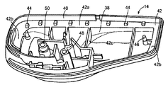
도 5 를 참조하여, 제 2 하우징 부분(14)의 사시도가 설명된다. 제 2 하우징 부분(14)은 개구(40) 그리고 제 2 하우징 부분(14)의 외측 주변부에 의해 적어도 부분적으로 한정되는 내측 구역(38)을 포함할 수 있다. 제 2 하우징 부분(14)은 제 2 하우징 부분(14)의 주변의 적어도 일 부분을 따라 위치되는 선반(shelf)(42)을 포함한다. 선반(42)은 적어도 제 1 세그먼트(42a), 제 2 세그먼트(들)(42b), 및 제 3 세그먼트(들)(42c)를 포함하며 여기서 제 2 세그먼트(42b) 및/또는 제 3 세그먼트(42c)는 실질적으로 제 1 세그먼트(42a)에 수직이다. 제 1 세그먼트(42a) 및 제 2 세그먼트(42b)는 제 2 하우징 부분(14)의 주변의 적어도 일 부분을 따라 위치될 수 있다. 제 3 세그먼트(42c)는 제 2 세그먼트(42b) 사이에 그리고 실질적으로 이에 평행하게 위치될 수 있다. 제 1 세그먼트(42a), 제 2 세그먼트(42b) 및 제 3 세그먼트(42c)는, 적어도 부분적으로는 인레이(18)를 위한 지지 구조물을 제공할 수 있다. 제 1 세그먼트(42a), 제 2 세그먼트(42b) 및 제 3 세그먼트(42c)는 각각의 길이들 및 폭들을 가질 수 있으며 여기서 제 1 세그먼트(42a)의 길이는 제 2 세그먼트(42b) 및/또는 제 3 세그먼트(42c)의 길이보다 더 클 수 있다. 당업자는 선반(42)이 하나 또는 둘 이상의 세그먼트들로 구성될 수 있는 것을 이해할 것이다. 대안적으로는, 하나 또는 둘 이상의 세그먼트들은 선반(42)으로부터 분리되거나 또는 떼어내 질 수 있다.
With reference to FIG. 5, a perspective view of the
제 2 하우징 부분(14)은 적어도 부분적으로 선반(42)의 일 부분 상에 배치되는 하나 또는 둘 이상의 돌기(44)들을 포함할 수 있다. 돌기(44)는 이 돌기(44)가 실질적으로는 선반(42)에 수직이도록 선반(42)으로부터 개구(40)를 향하여 외측으로 연장할 수 있다. 돌기(44)는 도 8 및 도 9 에 관하여 이하에 상세하게 논의되는 것과 같이 선반(42)으로부터 연장하는 돌기(44)의 양에 의해 한정되는 높이를 가질 수 있다. 정육면체형 또는 직사각형 프리즘형을 갖는 돌기(44)가 도시되지만, 돌기(44)는 원통형 또는 원뿔 형상과 같은 다른 형상들을 가질 수 있다.
The
돌기(44)는 인레이(18)와 선반(42) 사이의 상호 작용 및/또는 물리적 접촉이 감소되도록 인레이(18)를 선반(42)의 적어도 일 부분으로부터 이격시키도록 구성되며, 즉 안테나(30)는 선반(42)으로부터 이격된다. 돌기(44)는 제 2 하우징 부분(14)의 일부로서 형성될 수 있거나 또는 선반(42)에 부착되는 별개의 요소일 수 있다. 돌기(44)는 주기적 및/또는 비주기적 방식으로 선반(42) 상에 배치될 수 있다. 일 실시예에서, 돌기(44)는 선반(42)의 제 1 세그먼트(42a)를 따라 배치되지만 제 2 세그먼트(42b)를 따라서는 돌기들이 배치되지 않는다. 선반(42) 상에 배치된 돌기(44)들의 개수는 설계에 따라 변할 수 있다.
The
제 2 하우징 부분(14)은 인레이(18)와 맞물리도록 구성되는 하나 또는 둘 이상의 포스트(46)들을 포함할 수 있다. 인레이(18)와 맞물릴 때, 포스트(46)는 실질적으로 포스트(46)에 수직인 방향 또는 선반(42)에 평행한 방향으로의 인레이(18)의 이동을 감소시킬 수 있다. 제 2 하우징 부분(14)은 클램프(16)와 리셉터클(27)을 맞물리도록 배열되는 정합 요소(50)를 포함할 수 있다. 제 2 하우징 부분(14)은 떼어낼 수 있는 안전 요소를 수용하도록 배열되는 리셉터클(48)을 포함할 수 있다. 리셉터클(48)은 구멍(22)과 실질적으로 정렬될 수 있다. 예컨대, 제 1 하우징 부분(12) 및 제 2 하우징 부분(14)이 결합될 때, 떼어낼 수 있는 안전 요소는 구멍(22)을 통하여 제거 가능하게 삽입될 수 있고 리셉터클(48)에 수직인 방향으로의 떼어낼 수 있는 안전 요소의 이동이 감소되도록 리셉터클(48)에 의해 수용될 수 있다.
The
클램프(16) 및 인레이(18)와 맞물린 제 2 하우징 부분(14)의 사시도가 도 6 을 참조하여 설명된다. 인레이(18)는 인레이 구멍(36)이 포스트(46)들과 맞물리도록 제 2 하우징 부분(14)의 내부 내에 위치된다. 인레이(18)는 선반(42) 및 돌기(44)와 접촉하고 있다. 특히, 돌기(44)는 인레이(18)의 바람직한 조정된 주파수가 실질적으로 유지되도록 선반(42)의 제 1 세그먼트(42a)와 인레이(18), 즉 안테나(30) 사이의 상호 작용 및/또는 물리적 접촉을 감소시킨다. 예컨대, 제 1 세그먼트(42a)와 인레이(18) 사이의 상호 작용의 감소는 인레이(18)의 판독 주파수가 제 1 및 제 2 하우징 부분들에 의해 담겨질 때 15 내지 20 ㎒ 만큼 옮겨지는 것을 방지할 수 있고, 즉 실질적으로는 인레이(18)의 판독 주파수를 유지한다. 대안적으로는, 제 1 세그먼트(42a)와 인레이(18) 사이의 상호 작용은 850 ㎒ 와 같은 제 1 주파수와 950 ㎒ 와 같은 제 2 주파수 사이의 인레이(18)의 판독 주파수를 실질적으로 유지할 수 있다. 선반(42)의 제 2 세그먼트(42b)와 인레이(18) 사이의 상호 작용 및/또는 물리적 접촉은 돌기들이 선반의 제 2 세그먼트(42b) 및/또는 다른 세그먼트들 상에 필요하지 않도록 인레이(18)의 조정된 주파수를 실질적으로 변경시키지 않을 수 있다. 선반의 외측 주변부는 RFID 인레이(18)의 외측 주변부와 실질적으로 일치할 수 있다. 클램프(16)는 정합 요소(50)와 맞물리고 클램프(16)의 적어도 부분이 인레이(18)와 겹쳐지도록 위치될 수 있다. A perspective view of the
도 7 을 참조하여, 인레이(18)가 그 위에 배치된 제 2 하우징 부분(14)의 일 부분의 횡단면도가 설명된다. 돌기(44)는 인레이(18)와 선반(42) 사이의 상호 작용이 감소되도록 선반(42)으로부터 인레이(18)를 이격시킬 수 있으며, 즉 안테나(30)와 선반(42) 사이의 상호 작용은 안테나(30) 또는 인레이(18)를 돌기(44)를 통하여 선반(42)으로부터 이격시킴으로써 감소된다. 인레이(18)는 실질적으로 평면인 것으로 도시되지만, 당업자는 인레이(18)가 하나 또는 둘 이상의 돌기(44)들 상에 편평하게 놓이지 않는 얇은 가요성 기판으로 구성될 수 있다는 것을 인지할 것이다. 돌기(44)와 다수의 돌기(44)들 사이의 거리는 다른 요인들 중에서도 설계 요구를 기본으로 하여 변할 수 있다.
With reference to FIG. 7, a cross-sectional view of a portion of the
도 8 을 참조하여, 제 2 하우징 부분(14) 및 그 위에 배치된 인레이(18)의 횡단면도가 예시된다. 선반(42)은 제 2 하우징 부분(14)의 바닥 표면 위에서 연장하는 높이(h1)를 갖는다. 돌기(44)들은 각각의 돌기의 높이(h2)가 RFID 인레이(18)가 복수의 돌기들 상에 적어도 부분적으로 배치될 때 RFID 인레이(18)의 미리 결정된 판독 주파수를 실질적으로 유지하도록 구성되도록 선반(42) 위에서 연장하는 높이(h2)를 갖는다. 인레이(18)는 인레이(18)와 선반(42) 사이의 물리적 및 전기적 상호 작용이 감소되도록 선반(42) 및 돌기(44)들 위에 배치된다. 안테나(30)의 적어도 일 부분이 선반(42)과 겹칠 수 있지만, 선반(42)으로부터 이격될 수 있다. 선반(42)과 인레이(18) 및 안테나(30)의 적어도 일 부분의 겹침은 선반(42)과 인레이(18) 사이의 상호 작용을 여전히 감소시키면서 제 1 및 제 2 하우징 부분들의 크기가 최소로 유지되는 것을 허용한다.
With reference to FIG. 8, a cross sectional view of the
안테나(30)의 적어도 일 부분이 돌기(44)들로부터 오프셋된 것으로서 도 8 에 예시되지만, 안테나(30)의 적어도 일 부분은 돌기(44)들의 적어도 일 부분에서 겹치도록 대안적으로 구성될 수 있다. 구속 포스트(26)는 돌기(44)들 및/또는 구속 포스트(26)에 실질적으로 평행한 방향으로, 또는 선반(42)에 실질적으로 수직인 방향으로의 인레이(18)의 이동을 감소시키기 위해 선반(42)과 돌기(44)들에 대항하여 인레이(18)를 가압할 수 있다. 명확함의 목적들을 위해, 선반(42)의 다른 부분들, 제 1 하우징 부분(12) 및/또는 제 2 하우징 부분은 도 8 로부터 생략되었다.
Although at least a portion of the
도 9 를 참조하여, 제 2 하우징 부분(14) 및 그 위에 배치된 인레이(18)를 포함하는 다른 실시예의 횡단면이 본 발명의 원리들에 따라 제공된다. 도 9 는 제 2 하우징 부분(14)의 일 측 상의 선반(42)의 높이가 제 2 하우징 부분(14)의 다른 측 상의 선반 높이보다 더 낮은 것을 제외하고 도 8 의 요소들에 실질적으로 대응한다. 예컨대, 세그먼트(42b)와 같은 제 2 하우징 부분(14)의 일 측은 선반 높이(h3)를 가질 수 있는 반면 세그먼트(42a)와 같은 다른 측, 예컨대 말단 측(distal side)은 선반 높이(h1)를 가질 수 있다. 돌기(44)들은 높이(h2)를 갖는 선반(42) 상에 배치된다. 돌기(44)의 높이는 설계 요구를 기본으로 하여 다른 값들 가운데서도 0.05 내지 0.5 밀리미터(㎜)와 같이 변할 수 있다. 당업자는 다른 높이 구성들이 다른 요인들 가운데서도 제작, 비용 고려 사항들, 시스템(10)의 전체 크기, 인레이(18)의 크기 및/또는 시스템(10) 내의 다른 구성요소들의 위치 지정에 따라 규현될 수 있다는 것을 인지할 것이다.
With reference to FIG. 9, a cross section of another embodiment including a
도 8 의 실시예에 의한 것과 같이, 도 9 의 인레이(18)는 안테나(30)의 적어도 일 부분이 돌기(44)들에 의해 선반(42)으로부터 이격되도록 구성된다. 특히, 안테나(30)의 적어도 일 부분은 제 1 세그먼트(42a)와 같은 선반(42)의 적어도 일 부분과 겹칠 수 있다. 안테나(30)의 적어도 부분이 돌기(44)들로부터 오프셋 된 것으로서 도 9 에 예시되지만, 안테나(30)의 적어도 일 부분은 하나 또는 둘 이상의 돌기(44)들과 적어도 부분적으로 겹치도록 대안적으로 구성될 수 있다.
As by the embodiment of FIG. 8,
도 10 을 참조하여, 돌기(44)의 예시적인 측면도가 예시된다. 돌기(44)는 팁 세그먼트(44a) 및 본체 세그먼트(44b)를 갖는다. 팁 세그먼트(44a)는 선반(42)에 대해 말단에 있을 수 있고 실질적으로 기하학적 형상과 같은 하나 또는 둘 이상의 형상들을 가질 수 있다. 예컨대, 팁 세그먼트(44a)는 실질적으로 반구 형상을 가질 수 있다. 돌기(44)의 다른 실시예의 예시적인 측면도가 도 11 에 도시된다. 팁 세그먼트(44a) 및 본체 세그먼트(44b)는 팁 세그먼트(44a)가 실질적으로 피라미드 형상을 가질 수 있는 것을 제외하고 도 10 의 유사한 부분들에 실질적으로 대응할 수 있다. 도 12 는 돌기(44)의 다른 실시예의 측면도를 예시한다. 팁 세그먼트(44a) 및 본체 세그먼트(44b)는 팁 세그먼트(44a)가 실질적으로 직사각형 프리즘 형상을 가질 수 있는 것을 제외하고 도 10 의 유사한 세그먼트들에 실질적으로 대응할 수 있다. 도 13 은 돌기(44)의 다른 실시예의 측면도이다. 돌기(44)는 팁 세그먼트(44a)가 사다리꼴 형상을 갖는 것으로서 도 13 에 예시된 것을 제외하고 도 10 의 유사한 세그먼트들에 실질적으로 대응하는 팁 세그먼트(44a) 및 본체 세그먼트(44b)를 가질 수 있다.
10, an exemplary side view of the
도 10 내지 도 13 에 예시된 팁 세그먼트(44a)가 특별한 형상을 갖고 도시되어 있지만, 팁 세그먼트(44a)는 기하학적 및/또는 비-기하학적인 다른 형상들을 가질 수 있다. 도 5 에 예시된 각각의 돌기(44)의 형상은 실질적으로 서로 동일한 팁 세그먼트(44a) 형상을 가질 수 있다. 대안적으로는, 팁 세그먼트(44a)들의 형상은 설계 요구에 따라 변할 수 있다. 본체 세그먼트(44b)는 다른 형상들 중에서도 실질적으로 직사각형 형상 또는 원통형 형상과 같은 하나 또는 둘 이상의 형상들을 가질 수 있다. 본 발명의 시점에서 당업자는 돌기(44)가 하나 또는 둘 이상의 세그먼트들로 구성될 수 있다는 것을 이해할 것이다.
Although
본 발명이 본원에서 상기에 특별히 나타내고 설명된 것으로 제한되지 않는다는 것은 당업자에 의해 이해될 것이다. 게다가, 상기와 다르게 언급되지 않는 한, 모든 첨부된 도면들은 실척이 아닌 것에 주의해야 한다. 다양한 수정들 및 변형들이, 단지 이후의 청구항들에 의해서만 제한되는 본 발명의 범주 및 사상으로부터 이탈함이 없이 상기 교시들의 관점에서 가능하다.It will be understood by those skilled in the art that the present invention is not limited to those specifically shown and described herein above. In addition, it should be noted that all accompanying drawings are not to scale unless stated otherwise. Various modifications and variations are possible in view of the above teachings without departing from the scope and spirit of the invention, which is limited only by the following claims.
Claims (22)
RFID 요소(18); 및
내부 및 개구를 한정하는 제 1 하우징 부분(12), 및 상기 제 1 하우징 부분(12)과 정합하도록 구성되며 제 2 개구(40)를 한정하는 제 2 하우징 부분(14)을 포함하고,
상기 제 1 하우징 부분(12)의 내부는:
내측 주변부;
상기 내측 주변부의 적어도 일 부분의 주위에 배치되는 선반(42); 및
상기 선반(42)으로부터 상기 개구를 향하여 외측으로 연장하는 복수의 돌기(44)들을 포함하며,
상기 RFID 요소는 상기 복수의 돌기(44)들 상에 적어도 부분적으로 배치되어서 RFID 요소(18)와 상기 선반(42) 사이에서 상호작용 및 물리적 접촉 중 하나 이상이 감소되고,
상기 제 2 하우징 부분(14)은:
내부 표면; 및
복수의 포스트(46)들을 포함하며,
상기 복수의 포스트(46)들은 상기 내부 표면으로부터 상기 개구(40)를 향하여 외측으로 연장하고, 상기 제 1 하우징 부분(12)이 상기 제 2 하우징 부분(14)과 정합될 때 그리고 상기 RFID 요소(18)가 상기 복수의 돌기(44)들 상에 적어도 부분적으로 배치될 때 상기 복수의 포스트(46)들은 상기 RFID 요소(18)의 인레이 구멍(36)들과 정합되도록 구성되는,
무선 주파수 식별(RFID) 안전 시스템 태그.
A radio frequency identification (RFID) safety system tag.
RFID element 18; And
A first housing portion 12 defining an interior and an opening, and a second housing portion 14 configured to mate with the first housing portion 12 and defining a second opening 40;
The interior of the first housing portion 12 is:
Inner periphery;
A shelf 42 disposed around at least a portion of the inner periphery; And
A plurality of protrusions 44 extending outwardly from the shelf 42 toward the opening,
The RFID element is at least partially disposed on the plurality of protrusions 44 such that one or more of the interaction and physical contact between the RFID element 18 and the shelf 42 is reduced,
The second housing portion 14 is:
Internal surface; And
A plurality of posts 46,
The plurality of posts 46 extend outwardly from the inner surface towards the opening 40, and when the first housing portion 12 is mated with the second housing portion 14 and the RFID element ( The plurality of posts 46 are configured to mate with the inlay holes 36 of the RFID element 18 when 18 is at least partially disposed on the plurality of protrusions 44.
Radio Frequency Identification (RFID) Safety System Tag.
상기 선반(42)의 외측 주변부는 상기 RFID 요소(18)의 외측 주변부에 일치하는,
무선 주파수 식별(RFID) 안전 시스템 태그.
The method of claim 1,
The outer periphery of the shelf 42 corresponds to the outer periphery of the RFID element 18,
Radio Frequency Identification (RFID) Safety System Tag.
상기 선반(42)은 제 1 세그먼트(42a) 및 상기 제 1 세그먼트(42a)에 수직한 제 2 세그먼트(42b)에 의해 적어도 부분적으로 한정되며, 상기 제 1 세그먼트(42a)는 상기 제 2 세그먼트(42b)보다 더 긴 길이를 가지며, 상기 복수의 돌기(44)들은 상기 제 1 세그먼트(42a) 상에 배치되는,
무선 주파수 식별(RFID) 안전 시스템 태그.
The method of claim 2,
The shelf 42 is at least partly defined by a first segment 42a and a second segment 42b perpendicular to the first segment 42a, the first segment 42a being the second segment ( 42b), the plurality of protrusions 44 are disposed on the first segment 42a.
Radio Frequency Identification (RFID) Safety System Tag.
상기 복수의 돌기(44)들 각각은 RFID 요소(18)와 상기 선반(42) 사이에서 물리적 및 전기적 상호작용이 감소되도록 상기 선반(42)으로부터 RFID 요소(18)를 이격시키는 높이(h2)를 가지며, 상기 RFID 요소(18)가 상기 복수의 돌기(44)들 상에 배치될 때 각각의 돌기(44)의 높이(h2)로 인하여 제 1 주파수와 제 2 주파수 사이에서 상기 RFID 요소(18)의 미리 결정된 판독 주파수(read frequency)가 유지되도록 구성되는,
무선 주파수 식별(RFID) 안전 시스템 태그.
The method of claim 1,
Each of the plurality of protrusions 44 has a height h2 that separates the RFID element 18 from the shelf 42 such that physical and electrical interaction between the RFID element 18 and the shelf 42 is reduced. And the RFID element 18 between a first frequency and a second frequency due to the height h2 of each protrusion 44 when the RFID element 18 is disposed on the plurality of protrusions 44. Configured to maintain a predetermined read frequency of
Radio Frequency Identification (RFID) Safety System Tag.
상기 제 1 주파수는 850 메가헤르츠(Megahertz; MHz)이고, 상기 제 2 주파수는 950 MHz인,
무선 주파수 식별(RFID) 안전 시스템 태그.
The method of claim 4, wherein
The first frequency is 850 megahertz (MHz) and the second frequency is 950 MHz,
Radio Frequency Identification (RFID) Safety System Tag.
상기 복수의 돌기(44)들 중 각각의 돌기(44)는 상기 선반(42)에 대해 말단에 팁 세그먼트(44a)를 가지며, 상기 팁 세그먼트(44a)는 기하학적 형상을 갖는,
무선 주파수 식별(RFID) 안전 시스템 태그.
The method of claim 1,
Each of the protrusions 44 of the plurality of protrusions 44 has a tip segment 44a at the distal end with respect to the shelf 42, the tip segment 44a having a geometric shape,
Radio Frequency Identification (RFID) Safety System Tag.
상기 기하학적 형상은 반구 형상, 피라미드 형상 및 사다리꼴 형상 중 하나인,
무선 주파수 식별(RFID) 안전 시스템 태그.
The method of claim 6,
The geometric shape is one of hemispherical shape, pyramid shape and trapezoidal shape,
Radio Frequency Identification (RFID) Safety System Tag.
상기 RFID 요소(18)는 기판(32) 및 상기 기판(32) 상에 배치되는 안테나(30)를 가지며, 상기 안테나(30)의 적어도 일 부분은 상기 선반(42)과 겹쳐지고 상기 복수의 돌기(44)들에 의해 적어도 부분적으로 상기 선반(42)으로부터 이격되는,
무선 주파수 식별(RFID) 안전 시스템 태그.
The method of claim 1,
The RFID element 18 has a substrate 32 and an antenna 30 disposed on the substrate 32, at least a portion of the antenna 30 overlapping the shelf 42 and the plurality of protrusions. Spaced at least partially from the shelf 42 by
Radio Frequency Identification (RFID) Safety System Tag.
상기 제 2 하우징 부분(14)은 제 2 내부를 한정하고 상기 제 1 하우징 부분(12)과 정합하도록 구성되고, 상기 제 1 하우징 부분(12)과 상기 제 2 하우징 부분(14)은 정합될 때 체적을 형성하고,
상기 시스템 태그는 상기 체적 내에 배치되는 전자식 도난방지 감시(EAS) 요소(28)를 더 포함하며,
상기 RFID 요소는 상기 체적 내에 배치되는,
무선 주파수 식별(RFID) 안전 시스템 태그.
The method of claim 8,
The second housing portion 14 is configured to define a second interior and to mate with the first housing portion 12, when the first housing portion 12 and the second housing portion 14 are mated. To form a volume,
The system tag further includes an electronic anti-theft monitoring (EAS) element 28 disposed within the volume,
The RFID element is disposed within the volume,
Radio Frequency Identification (RFID) Safety System Tag.
상기 제 1 하우징 부분(12)이 상기 제 2 하우징 부분(14)과 정합될 때 그리고 상기 RFID 요소(18)가 상기 복수의 돌기(44)들 상에 적어도 부분적으로 배치될 때 상기 제 1 하우징 부분(12)은 상기 RFID 요소(18)의 적어도 안테나(30) 및 IC 칩(34) 중 하나 이상과 물리적으로 접촉하지 않도록 구성되는 복수의 구속 포스트(26)들을 더 포함하는,
무선 주파수 식별(RFID) 안전 시스템 태그.
The method of claim 1,
The first housing portion when the first housing portion 12 is mated with the second housing portion 14 and when the RFID element 18 is at least partially disposed on the plurality of protrusions 44. (12) further includes a plurality of restraining posts 26 configured to not be in physical contact with at least one of the antenna 30 and the IC chip 34 of the RFID element 18,
Radio Frequency Identification (RFID) Safety System Tag.
Applications Claiming Priority (3)
| Application Number | Priority Date | Filing Date | Title |
|---|---|---|---|
| US201161630494P | 2011-12-13 | 2011-12-13 | |
| US61/630,494 | 2011-12-13 | ||
| PCT/US2012/046519 WO2013089826A1 (en) | 2011-12-13 | 2012-07-12 | Radio frequency id tag having structure for inlay spacing |
Publications (2)
| Publication Number | Publication Date |
|---|---|
| KR20140106696A KR20140106696A (en) | 2014-09-03 |
| KR102062053B1 true KR102062053B1 (en) | 2020-01-03 |
Family
ID=46640756
Family Applications (1)
| Application Number | Title | Priority Date | Filing Date |
|---|---|---|---|
| KR1020147019551A Active KR102062053B1 (en) | 2011-12-13 | 2012-07-12 | Radio frequency id tag having structure for inlay spacing |
Country Status (7)
| Country | Link |
|---|---|
| US (1) | US8967486B2 (en) |
| EP (1) | EP2791872B1 (en) |
| KR (1) | KR102062053B1 (en) |
| CN (1) | CN104272325B (en) |
| AU (1) | AU2012352974B2 (en) |
| CA (1) | CA2861188C (en) |
| WO (1) | WO2013089826A1 (en) |
Families Citing this family (13)
| Publication number | Priority date | Publication date | Assignee | Title |
|---|---|---|---|---|
| US9218730B2 (en) * | 2014-02-26 | 2015-12-22 | Tyco Fire & Security Gmbh | Security tag with magnetic gate |
| US10096217B2 (en) * | 2016-05-11 | 2018-10-09 | Braeburn Asset Holdings, Llc | Security system and security tag assembly |
| CN110622628B (en) * | 2017-03-15 | 2021-10-26 | 香港物流及供应链管理应用技术研发中心 | Radio frequency communication guiding device |
| WO2019224575A1 (en) | 2018-05-22 | 2019-11-28 | Tyco Fire & Security Gmbh | Elongate flexible tag |
| EP3979135A4 (en) * | 2019-05-28 | 2023-06-14 | Kyocera Corporation | Rfid tag |
| US12223814B2 (en) | 2019-09-16 | 2025-02-11 | Sensormatic Electronics, LLC | Security tag for textiles using conductive thread |
| US11443160B2 (en) | 2019-09-18 | 2022-09-13 | Sensormatic Electronics, LLC | Systems and methods for laser tuning and attaching RFID tags to products |
| US10970613B1 (en) | 2019-09-18 | 2021-04-06 | Sensormatic Electronics, LLC | Systems and methods for providing tags adapted to be incorporated with or in items |
| US11055588B2 (en) | 2019-11-27 | 2021-07-06 | Sensormatic Electronics, LLC | Flexible water-resistant sensor tag |
| US12524640B2 (en) | 2019-11-27 | 2026-01-13 | Sensormatic Electronics, LLC | Flexible water-resistant sensor tag |
| US11755874B2 (en) | 2021-03-03 | 2023-09-12 | Sensormatic Electronics, LLC | Methods and systems for heat applied sensor tag |
| US11869324B2 (en) | 2021-12-23 | 2024-01-09 | Sensormatic Electronics, LLC | Securing a security tag into an article |
| US12536401B2 (en) | 2022-08-31 | 2026-01-27 | Sensormatic Electronics, LLC | Security tag |
Citations (5)
| Publication number | Priority date | Publication date | Assignee | Title |
|---|---|---|---|---|
| JP2001297381A (en) | 2000-04-11 | 2001-10-26 | Kubota Corp | Anti-theft tag |
| JP2004506270A (en) | 2000-08-08 | 2004-02-26 | センサーマチック・エレクトロニックス・コーポレーション | Electronic monitoring tag |
| US20110001620A1 (en) * | 2009-07-01 | 2011-01-06 | Sensormatic Electronics, LLC | Combination eas and rfid security tag having structure for orienting a hybrid antenna rfid element |
| US20110168920A1 (en) * | 2010-01-12 | 2011-07-14 | Landauer, Inc. | Novel filters for use in dosimetry |
| WO2011159651A1 (en) | 2010-06-14 | 2011-12-22 | Avery Dennison Corporation | Security and inventory management tag and system therefor |
Family Cites Families (7)
| Publication number | Priority date | Publication date | Assignee | Title |
|---|---|---|---|---|
| US4642640A (en) | 1983-04-25 | 1987-02-10 | Sensormatic Electronics Corporation | Signal receptor-reradiator and surveillance tag using the same |
| US5426419A (en) * | 1993-01-14 | 1995-06-20 | Sensormatic Electronics Corporation | Security tag having arcuate channel and detacher apparatus for same |
| US6121878A (en) | 1998-05-01 | 2000-09-19 | Intermec Ip Corp. | System for controlling assets |
| US5986562A (en) * | 1998-09-11 | 1999-11-16 | Brady Worldwide, Inc. | RFID tag holder for non-RFID tag |
| US7474222B2 (en) | 2003-05-06 | 2009-01-06 | Xiao Hui Yang | Disposable, single use security tag |
| US7724146B2 (en) * | 2004-11-17 | 2010-05-25 | Sensormatic Electronics, LLC | Magnetically releasable electronic article surveillance tag |
| JP5457741B2 (en) * | 2009-07-01 | 2014-04-02 | 富士通株式会社 | RFID tag |
-
2012
- 2012-07-11 US US13/546,476 patent/US8967486B2/en active Active
- 2012-07-12 CN CN201280069293.8A patent/CN104272325B/en active Active
- 2012-07-12 EP EP12745726.5A patent/EP2791872B1/en active Active
- 2012-07-12 KR KR1020147019551A patent/KR102062053B1/en active Active
- 2012-07-12 WO PCT/US2012/046519 patent/WO2013089826A1/en not_active Ceased
- 2012-07-12 CA CA2861188A patent/CA2861188C/en active Active
- 2012-07-12 AU AU2012352974A patent/AU2012352974B2/en active Active
Patent Citations (5)
| Publication number | Priority date | Publication date | Assignee | Title |
|---|---|---|---|---|
| JP2001297381A (en) | 2000-04-11 | 2001-10-26 | Kubota Corp | Anti-theft tag |
| JP2004506270A (en) | 2000-08-08 | 2004-02-26 | センサーマチック・エレクトロニックス・コーポレーション | Electronic monitoring tag |
| US20110001620A1 (en) * | 2009-07-01 | 2011-01-06 | Sensormatic Electronics, LLC | Combination eas and rfid security tag having structure for orienting a hybrid antenna rfid element |
| US20110168920A1 (en) * | 2010-01-12 | 2011-07-14 | Landauer, Inc. | Novel filters for use in dosimetry |
| WO2011159651A1 (en) | 2010-06-14 | 2011-12-22 | Avery Dennison Corporation | Security and inventory management tag and system therefor |
Also Published As
| Publication number | Publication date |
|---|---|
| EP2791872A1 (en) | 2014-10-22 |
| WO2013089826A1 (en) | 2013-06-20 |
| CA2861188C (en) | 2019-11-26 |
| CN104272325B (en) | 2017-12-01 |
| AU2012352974B2 (en) | 2017-10-19 |
| CN104272325A (en) | 2015-01-07 |
| CA2861188A1 (en) | 2013-06-20 |
| EP2791872B1 (en) | 2017-09-06 |
| KR20140106696A (en) | 2014-09-03 |
| US20130146668A1 (en) | 2013-06-13 |
| US8967486B2 (en) | 2015-03-03 |
| HK1202956A1 (en) | 2015-10-09 |
| AU2012352974A1 (en) | 2014-08-07 |
Similar Documents
| Publication | Publication Date | Title |
|---|---|---|
| KR102062053B1 (en) | Radio frequency id tag having structure for inlay spacing | |
| EP2449196B1 (en) | Combination eas and rfid security tag having structure for orienting a hybrid antenna rfid element | |
| US8955756B2 (en) | Security system tag having combined clamp and antenna | |
| AU2004241593B2 (en) | EAS/RFID identification hard tags | |
| HK1202956B (en) | Radio frequency id tag having structure for inlay spacing | |
| KR200370649Y1 (en) | Radio frequency identification tag | |
| EP2543005B1 (en) | Security system tag having combined clamp and antenna | |
| KR20070032059A (en) | EAS / RFID Identification Hard Tag | |
| HK1167008B (en) | Combination eas and rfid security tag having structure for orienting a hybrid antenna rfid element | |
| HK1176724B (en) | Security system tag having combined clamp and antenna |
Legal Events
| Date | Code | Title | Description |
|---|---|---|---|
| PA0105 | International application |
St.27 status event code: A-0-1-A10-A15-nap-PA0105 |
|
| P11-X000 | Amendment of application requested |
St.27 status event code: A-2-2-P10-P11-nap-X000 |
|
| P13-X000 | Application amended |
St.27 status event code: A-2-2-P10-P13-nap-X000 |
|
| PG1501 | Laying open of application |
St.27 status event code: A-1-1-Q10-Q12-nap-PG1501 |
|
| P11-X000 | Amendment of application requested |
St.27 status event code: A-2-2-P10-P11-nap-X000 |
|
| P13-X000 | Application amended |
St.27 status event code: A-2-2-P10-P13-nap-X000 |
|
| PA0201 | Request for examination |
St.27 status event code: A-1-2-D10-D11-exm-PA0201 |
|
| E902 | Notification of reason for refusal | ||
| PE0902 | Notice of grounds for rejection |
St.27 status event code: A-1-2-D10-D21-exm-PE0902 |
|
| T11-X000 | Administrative time limit extension requested |
St.27 status event code: U-3-3-T10-T11-oth-X000 |
|
| T11-X000 | Administrative time limit extension requested |
St.27 status event code: U-3-3-T10-T11-oth-X000 |
|
| T11-X000 | Administrative time limit extension requested |
St.27 status event code: U-3-3-T10-T11-oth-X000 |
|
| T11-X000 | Administrative time limit extension requested |
St.27 status event code: U-3-3-T10-T11-oth-X000 |
|
| E13-X000 | Pre-grant limitation requested |
St.27 status event code: A-2-3-E10-E13-lim-X000 |
|
| P11-X000 | Amendment of application requested |
St.27 status event code: A-2-2-P10-P11-nap-X000 |
|
| P13-X000 | Application amended |
St.27 status event code: A-2-2-P10-P13-nap-X000 |
|
| E701 | Decision to grant or registration of patent right | ||
| PE0701 | Decision of registration |
St.27 status event code: A-1-2-D10-D22-exm-PE0701 |
|
| PR0701 | Registration of establishment |
St.27 status event code: A-2-4-F10-F11-exm-PR0701 |
|
| PR1002 | Payment of registration fee |
St.27 status event code: A-2-2-U10-U12-oth-PR1002 Fee payment year number: 1 |
|
| PG1601 | Publication of registration |
St.27 status event code: A-4-4-Q10-Q13-nap-PG1601 |
|
| PR1001 | Payment of annual fee |
St.27 status event code: A-4-4-U10-U11-oth-PR1001 Fee payment year number: 4 |
|
| PR1001 | Payment of annual fee |
St.27 status event code: A-4-4-U10-U11-oth-PR1001 Fee payment year number: 5 |
|
| PR1001 | Payment of annual fee |
St.27 status event code: A-4-4-U10-U11-oth-PR1001 Fee payment year number: 6 |
|
| PR1001 | Payment of annual fee |
St.27 status event code: A-4-4-U10-U11-oth-PR1001 Fee payment year number: 7 |
|
| U11 | Full renewal or maintenance fee paid |
Free format text: ST27 STATUS EVENT CODE: A-4-4-U10-U11-OTH-PR1001 (AS PROVIDED BY THE NATIONAL OFFICE) Year of fee payment: 7 |