KR102051896B1 - Cordless blind apparatus - Google Patents
Cordless blind apparatus Download PDFInfo
- Publication number
- KR102051896B1 KR102051896B1 KR1020180002823A KR20180002823A KR102051896B1 KR 102051896 B1 KR102051896 B1 KR 102051896B1 KR 1020180002823 A KR1020180002823 A KR 1020180002823A KR 20180002823 A KR20180002823 A KR 20180002823A KR 102051896 B1 KR102051896 B1 KR 102051896B1
- Authority
- KR
- South Korea
- Prior art keywords
- roll
- rotation
- take
- screen member
- driving motor
- Prior art date
- Legal status (The legal status is an assumption and is not a legal conclusion. Google has not performed a legal analysis and makes no representation as to the accuracy of the status listed.)
- Active
Links
Images


Classifications
-
- E—FIXED CONSTRUCTIONS
- E06—DOORS, WINDOWS, SHUTTERS, OR ROLLER BLINDS IN GENERAL; LADDERS
- E06B—FIXED OR MOVABLE CLOSURES FOR OPENINGS IN BUILDINGS, VEHICLES, FENCES OR LIKE ENCLOSURES IN GENERAL, e.g. DOORS, WINDOWS, BLINDS, GATES
- E06B9/00—Screening or protective devices for wall or similar openings, with or without operating or securing mechanisms; Closures of similar construction
- E06B9/56—Operating, guiding or securing devices or arrangements for roll-type closures; Spring drums; Tape drums; Counterweighting arrangements therefor
- E06B9/60—Spring drums operated only by closure members
-
- E—FIXED CONSTRUCTIONS
- E06—DOORS, WINDOWS, SHUTTERS, OR ROLLER BLINDS IN GENERAL; LADDERS
- E06B—FIXED OR MOVABLE CLOSURES FOR OPENINGS IN BUILDINGS, VEHICLES, FENCES OR LIKE ENCLOSURES IN GENERAL, e.g. DOORS, WINDOWS, BLINDS, GATES
- E06B9/00—Screening or protective devices for wall or similar openings, with or without operating or securing mechanisms; Closures of similar construction
- E06B9/24—Screens or other constructions affording protection against light, especially against sunshine; Similar screens for privacy or appearance; Slat blinds
- E06B9/40—Roller blinds
- E06B9/42—Parts or details of roller blinds, e.g. suspension devices, blind boxes
-
- E—FIXED CONSTRUCTIONS
- E06—DOORS, WINDOWS, SHUTTERS, OR ROLLER BLINDS IN GENERAL; LADDERS
- E06B—FIXED OR MOVABLE CLOSURES FOR OPENINGS IN BUILDINGS, VEHICLES, FENCES OR LIKE ENCLOSURES IN GENERAL, e.g. DOORS, WINDOWS, BLINDS, GATES
- E06B9/00—Screening or protective devices for wall or similar openings, with or without operating or securing mechanisms; Closures of similar construction
- E06B9/24—Screens or other constructions affording protection against light, especially against sunshine; Similar screens for privacy or appearance; Slat blinds
- E06B9/40—Roller blinds
-
- E—FIXED CONSTRUCTIONS
- E06—DOORS, WINDOWS, SHUTTERS, OR ROLLER BLINDS IN GENERAL; LADDERS
- E06B—FIXED OR MOVABLE CLOSURES FOR OPENINGS IN BUILDINGS, VEHICLES, FENCES OR LIKE ENCLOSURES IN GENERAL, e.g. DOORS, WINDOWS, BLINDS, GATES
- E06B9/00—Screening or protective devices for wall or similar openings, with or without operating or securing mechanisms; Closures of similar construction
- E06B9/56—Operating, guiding or securing devices or arrangements for roll-type closures; Spring drums; Tape drums; Counterweighting arrangements therefor
- E06B9/62—Counterweighting arrangements
-
- E—FIXED CONSTRUCTIONS
- E06—DOORS, WINDOWS, SHUTTERS, OR ROLLER BLINDS IN GENERAL; LADDERS
- E06B—FIXED OR MOVABLE CLOSURES FOR OPENINGS IN BUILDINGS, VEHICLES, FENCES OR LIKE ENCLOSURES IN GENERAL, e.g. DOORS, WINDOWS, BLINDS, GATES
- E06B9/00—Screening or protective devices for wall or similar openings, with or without operating or securing mechanisms; Closures of similar construction
- E06B9/56—Operating, guiding or securing devices or arrangements for roll-type closures; Spring drums; Tape drums; Counterweighting arrangements therefor
- E06B9/68—Operating devices or mechanisms, e.g. with electric drive
- E06B9/72—Operating devices or mechanisms, e.g. with electric drive comprising an electric motor positioned inside the roller
-
- E—FIXED CONSTRUCTIONS
- E06—DOORS, WINDOWS, SHUTTERS, OR ROLLER BLINDS IN GENERAL; LADDERS
- E06B—FIXED OR MOVABLE CLOSURES FOR OPENINGS IN BUILDINGS, VEHICLES, FENCES OR LIKE ENCLOSURES IN GENERAL, e.g. DOORS, WINDOWS, BLINDS, GATES
- E06B9/00—Screening or protective devices for wall or similar openings, with or without operating or securing mechanisms; Closures of similar construction
- E06B9/56—Operating, guiding or securing devices or arrangements for roll-type closures; Spring drums; Tape drums; Counterweighting arrangements therefor
- E06B9/68—Operating devices or mechanisms, e.g. with electric drive
- E06B9/74—Operating devices or mechanisms, e.g. with electric drive adapted for selective electrical or manual operation
-
- E—FIXED CONSTRUCTIONS
- E06—DOORS, WINDOWS, SHUTTERS, OR ROLLER BLINDS IN GENERAL; LADDERS
- E06B—FIXED OR MOVABLE CLOSURES FOR OPENINGS IN BUILDINGS, VEHICLES, FENCES OR LIKE ENCLOSURES IN GENERAL, e.g. DOORS, WINDOWS, BLINDS, GATES
- E06B9/00—Screening or protective devices for wall or similar openings, with or without operating or securing mechanisms; Closures of similar construction
- E06B9/56—Operating, guiding or securing devices or arrangements for roll-type closures; Spring drums; Tape drums; Counterweighting arrangements therefor
- E06B9/80—Safety measures against dropping or unauthorised opening; Braking or immobilising devices; Devices for limiting unrolling
- E06B9/82—Safety measures against dropping or unauthorised opening; Braking or immobilising devices; Devices for limiting unrolling automatic
- E06B9/90—Safety measures against dropping or unauthorised opening; Braking or immobilising devices; Devices for limiting unrolling automatic for immobilising the closure member in various chosen positions
-
- F—MECHANICAL ENGINEERING; LIGHTING; HEATING; WEAPONS; BLASTING
- F16—ENGINEERING ELEMENTS AND UNITS; GENERAL MEASURES FOR PRODUCING AND MAINTAINING EFFECTIVE FUNCTIONING OF MACHINES OR INSTALLATIONS; THERMAL INSULATION IN GENERAL
- F16H—GEARING
- F16H1/00—Toothed gearings for conveying rotary motion
- F16H1/28—Toothed gearings for conveying rotary motion with gears having orbital motion
-
- E—FIXED CONSTRUCTIONS
- E06—DOORS, WINDOWS, SHUTTERS, OR ROLLER BLINDS IN GENERAL; LADDERS
- E06B—FIXED OR MOVABLE CLOSURES FOR OPENINGS IN BUILDINGS, VEHICLES, FENCES OR LIKE ENCLOSURES IN GENERAL, e.g. DOORS, WINDOWS, BLINDS, GATES
- E06B9/00—Screening or protective devices for wall or similar openings, with or without operating or securing mechanisms; Closures of similar construction
- E06B9/56—Operating, guiding or securing devices or arrangements for roll-type closures; Spring drums; Tape drums; Counterweighting arrangements therefor
- E06B9/68—Operating devices or mechanisms, e.g. with electric drive
- E06B2009/6809—Control
- E06B2009/6818—Control using sensors
-
- E—FIXED CONSTRUCTIONS
- E06—DOORS, WINDOWS, SHUTTERS, OR ROLLER BLINDS IN GENERAL; LADDERS
- E06B—FIXED OR MOVABLE CLOSURES FOR OPENINGS IN BUILDINGS, VEHICLES, FENCES OR LIKE ENCLOSURES IN GENERAL, e.g. DOORS, WINDOWS, BLINDS, GATES
- E06B9/00—Screening or protective devices for wall or similar openings, with or without operating or securing mechanisms; Closures of similar construction
- E06B9/56—Operating, guiding or securing devices or arrangements for roll-type closures; Spring drums; Tape drums; Counterweighting arrangements therefor
- E06B9/68—Operating devices or mechanisms, e.g. with electric drive
- E06B9/72—Operating devices or mechanisms, e.g. with electric drive comprising an electric motor positioned inside the roller
- E06B2009/725—Operating devices or mechanisms, e.g. with electric drive comprising an electric motor positioned inside the roller with epicyclic or planetary gear train
-
- F—MECHANICAL ENGINEERING; LIGHTING; HEATING; WEAPONS; BLASTING
- F16—ENGINEERING ELEMENTS AND UNITS; GENERAL MEASURES FOR PRODUCING AND MAINTAINING EFFECTIVE FUNCTIONING OF MACHINES OR INSTALLATIONS; THERMAL INSULATION IN GENERAL
- F16H—GEARING
- F16H1/00—Toothed gearings for conveying rotary motion
- F16H1/28—Toothed gearings for conveying rotary motion with gears having orbital motion
- F16H2001/289—Toothed gearings for conveying rotary motion with gears having orbital motion comprising two or more coaxial and identical sets of orbital gears, e.g. for distributing torque between the coaxial sets
Landscapes
- Engineering & Computer Science (AREA)
- Structural Engineering (AREA)
- Architecture (AREA)
- Civil Engineering (AREA)
- General Engineering & Computer Science (AREA)
- Mechanical Engineering (AREA)
- Operating, Guiding And Securing Of Roll- Type Closing Members (AREA)
- Power-Operated Mechanisms For Wings (AREA)
Abstract
수동, 반자동, 자동 방식 등의 여러 가지 방식으로 편리하게 작동시킬 수 있는 코드리스 블라인드 장치가 제공된다. 코드리스 블라인드 장치는, 권취롤, 권취롤에 권취되거나 권출되는 스크린부재, 권취롤에 회전 구동력을 제공하는 구동모터, 스크린부재 하단에 연결되어 중력에 의해 권취롤에 스크린부재가 권출되는 제1방향으로 토크를 인가하는 웨이트부재, 권취롤에 탄성력을 가하여 스크린부재가 권취되는 제2방향으로 토크를 인가하는 토션스프링, 및 구동모터와 권취롤 사이에서 구동모터가 제공하는 회전 구동력을 권취롤에 전달하거나, 토션스프링이 권취롤에 제공하는 토크를 구동모터로 전달하여, 양방향으로 동력을 전달하는 회전변환모듈을 포함하며, 구동모터가 구동력을 발생시키지 않는 상태에서, 토션스프링에 의해 인가된 토크와, 웨이트부재에 의해 인가된 토크와, 회전변환모듈과 구동모터에 의한 저항력이 평형을 이루어 스크린부재가 정지한 채로 유지되고, 웨이트부재에 상방 또는 하방으로 외력이 작용하면, 힘의 평형이 깨져 스크린부재가 권취롤에 권취되거나 권출된다.A cordless blind device is provided which can be conveniently operated in various ways such as manual, semi-automatic or automatic. The cordless blind apparatus includes a winding roll, a screen member wound or unwound on the take-up roll, a drive motor providing a rotational driving force to the take-up roll, and connected to a lower end of the screen member in a first direction in which the screen member is unwound on the take-up roll by gravity. The weight member for applying torque, the torsion spring for applying torque in the second direction in which the screen member is wound by applying elastic force to the take-up roll, and transmitting the rotational driving force provided by the drive motor between the drive motor and the take-up roll to the take-up roll or And a rotation conversion module which transmits power in both directions by transmitting the torque provided by the torsion spring to the take-up roll to the driving motor, and the torque applied by the torsion spring in a state where the driving motor does not generate a driving force, The torque applied by the weight member and the resistance by the rotation conversion module and the driving motor are balanced to stop the screen member. Is maintained at, if an external force acts in the upward or downward direction of the weight member, the equilibrium of forces is broken and the screen member is wound or unwound on a winding roll.
Description
본 발명은 당김줄(코드) 없이 작동하는 코드리스 블라인드 장치에 관한 것으로서, 더욱 상세하게는, 수동, 반자동, 자동 방식 등의 여러 가지 방식으로 편리하게 작동시킬 수 있는 코드리스 블라인드 장치에 관한 것이다.BACKGROUND OF THE
블라인드 장치는 창가에 설치되어 창을 개폐하는 데 사용된다. 블라인드 장치는 창의 차폐량을 조절할 수 있는 구조로 되어 있어 블라인드 장치로 채광량을 변화시킬 수 있다. 블라인드 장치는 이와 같이 채광량 등을 조절하는 데에 사용될 뿐만 아니라 창가에 설치하여 실내를 장식하기 위한 장식적인 요소로도 사용될 수 있다. 블라인드 장치는 스크린이나 슬래트 등의 차폐구조를 포함할 수 있다.The blind device is installed near the window and is used to open and close the window. The blind device has a structure that can control the shielding amount of the window can be changed by the blind device. The blind apparatus may be used not only to adjust the amount of light and the like, but also may be used as a decorative element for decorating the interior by installing it near a window. The blind device may include a shielding structure such as a screen or a slat.
스크린은 블라인드 장치에 널리 사용되는 차폐구조 중 하나로 직물 등의 소재로 형성된다. 이러한 스크린을 롤에 감거나 롤에서 풀어 펼침으로써 차폐량을 조절할 수 있다. 이와 같이 스크린이 포함된 블라인드 장치는 스크린이 감기는 롤을 회전시키기 위한 구조도 필요하다. 롤은 창의 상단에 높게 설치되므로, 창의 하단까지 내려오는 당김줄(코드)로 장력을 가하여 롤을 회전시킬 수 있다.The screen is one of shielding structures widely used in blind devices and is formed of a material such as fabric. The amount of shielding can be adjusted by winding this screen on a roll or unrolling it from the roll. As such, the blind apparatus including the screen also needs a structure for rotating the roll on which the screen is wound. Since the roll is installed high at the top of the window, the roll can be rotated by applying tension with a pull cord (cord) that descends to the bottom of the window.
즉, 종래 블라인드 장치를 조작하기 위한 구조로 당김줄 등을 많이 사용하였다. 당김줄은 롤에 장력을 가하여 회전시킬 수 있도록 롤에 연결하면 되므로 상대적으로 간단하게 설치하여 사용할 수 있다. 그러나, 당김줄이 길어지면 장애물로 작용하여 사람이 걸려 넘어지는 등의 사고가 발생할 수 있고, 당김줄을 조작할 때 장력이 롤의 일 측에만 편중되어 기능고장이 발생하는 경우도 많았으며, 당김줄이 제대로 연결되지 않은 경우 이를 조작하기 위해 불필요하게 과도한 힘이 소모되는 문제도 있었다. 따라서 보다 편리하게 블라인드 장치를 조작할 수 있는 구조가 필요하였다.That is, a pull string or the like was used as a structure for operating a conventional blind apparatus. The pulling line can be installed and used relatively simply because it is connected to the roll so that it can be rotated by applying tension to the roll. However, when the pulling string is lengthened, it may act as an obstacle, causing an accident such as a person falling over.In addition, when the pull string is manipulated, tension tends to be biased on only one side of the roll, which causes malfunction. There was also a problem in that excessively excessive power was consumed to manipulate the strings if they were not properly connected. Therefore, there is a need for a structure that can operate the blind device more conveniently.
본 발명의 기술적 과제는, 이러한 문제점을 해결하기 위한 것으로서, 당김줄(코드)없이 편리하게 작동시킬 수 있는 코드리스 블라인드 장치를 제공하는 것이며, 특히 수동, 반자동, 자동 방식 등의 여러 가지 방식으로 작동시킬 수 있는 코드리스 블라인드 장치를 제공하는 것이다.The technical problem of the present invention is to solve this problem, and to provide a cordless blind device that can be conveniently operated without a pull line (cord), in particular to operate in a variety of ways, such as manual, semi-automatic, automatic It is to provide a cordless blind device that can be.
본 발명의 기술적 과제는 이상에서 언급한 과제로 제한되지 않으며 언급되지 않은 또 다른 기술적 과제들은 아래의 기재로부터 당업자에게 명확하게 이해될 수 있을 것이다.The technical problem of the present invention is not limited to the above-mentioned problem, and other technical problems not mentioned will be clearly understood by those skilled in the art from the following description.
본 발명에 의한 코드리스 블라인드 장치는, 회전축에 결합된 권취롤; 상기 권취롤에 권취되거나 권출되는 스크린부재; 상기 권취롤에 회전 구동력을 제공하여 상기 스크린부재를 권취하거나 권출하는 구동모터; 상기 스크린부재 하단에 연결되어 중력에 의해 상기 권취롤에 상기 스크린부재가 권출되는 제1방향으로 토크를 인가하는 웨이트부재; 상기 권취롤에 탄성력을 가하여 상기 스크린부재가 권취되는 제2방향으로 토크를 인가하는 토션스프링; 및 상기 구동모터와 상기 권취롤 사이에 결합되며, 상기 구동모터가 제공하는 회전 구동력을 상기 권취롤에 전달하거나, 상기 토션스프링이 상기 권취롤에 제공하는 토크를 상기 구동모터로 전달하여, 양방향으로 동력을 전달하는 회전변환모듈을 포함하며, 상기 구동모터가 구동력을 발생시키지 않는 상태에서, 상기 토션스프링에 의해 인가된 토크와, 상기 웨이트부재에 의해 인가된 토크와, 상기 회전변환모듈과 상기 구동모터에 의한 저항력이 평형을 이루어 상기 스크린부재가 정지한 채로 유지되고, 상기 웨이트부재에 상방 또는 하방으로 외력이 작용하면, 힘의 평형이 깨져 상기 스크린부재가 상기 권취롤에 권취되거나 권출된다.Cordless blind device according to the invention, the winding roll coupled to the rotating shaft; A screen member wound or unwound on the winding roll; A driving motor for winding or unwinding the screen member by providing a rotational driving force to the winding roll; A weight member connected to a lower end of the screen member to apply torque to the take-up roll in a first direction by which the screen member is unwound by gravity; A torsion spring that applies an elastic force to the winding roll to apply torque in a second direction in which the screen member is wound; And coupled between the drive motor and the take-up roll, transfer the rotational driving force provided by the drive motor to the take-up roll, or transfer the torque provided by the torsion spring to the take-up roll to the drive motor, in both directions It includes a rotation conversion module for transmitting power, the torque applied by the torsion spring, the torque applied by the weight member, the rotation conversion module and the drive in a state that the drive motor does not generate a driving force When the resistance by the motor is balanced and the screen member is kept stationary, and the external force acts upward or downward on the weight member, the balance of the force is broken and the screen member is wound or unwound on the take-up roll.
상기 토션스프링이 인가하는 토크는 상기 회전변환모듈의 마찰저항력과 상기 구동모터의 회생저항력의 합력보다 크게 설정될 수 있다.The torque applied by the torsion spring may be set greater than the sum of the frictional resistance of the rotation conversion module and the regenerative resistance of the drive motor.
상기 회전변환모듈은, 상기 구동모터에 연결되어 함께 회전하는 제1회전요소와, 상기 권취롤에 연결되어 회전하는 제2회전요소와, 상기 제1회전요소와 상기 제2회전요소 사이에 개재되어 동력을 전달하는 회전매개유닛을 포함할 수 있다.The rotation conversion module is interposed between the first rotating element connected to the drive motor to rotate together, the second rotating element connected to the winding roll to rotate, and the first rotating element and the second rotating element. It may include a rotation media unit for transmitting power.
상기 제1회전요소와 상기 제2회전요소는 회전중심이 동일 축상에 위치하고, 상기 회전매개유닛은 상기 제1회전요소의 회전속도를 감속하여 상기 제2회전요소에 전달할 수 있다.The first rotation element and the second rotation element may be located on the same axis of rotation, and the rotation medium unit may reduce the rotation speed of the first rotation element and transmit the same to the second rotation element.
상기 제1회전요소는 제1태양기어를 포함하고, 상기 회전매개유닛은 상기 제1태양기어 둘레를 공전하는 복수 개의 제1유성기어와, 상기 제1유성기어의 회전축이 결합된 제1회전판과, 상기 제1유성기어가 결합된 반대면의 상기 제1회전판에 결합된 제2태양기어를 포함하고, 상기 제2회전요소는 상기 제2태양기어 둘레를 공전하는 복수 개의 제2유성기어와, 상기 제2유성기어의 회전축이 결합된 제2회전판을 포함할 수 있다.The first rotating element includes a first sun gear, wherein the rotation medium unit includes a plurality of first planetary gears revolving around the first sun gear, a first rotating plate to which the rotation shaft of the first planetary gear is coupled; And a second sun gear coupled to the first rotating plate on the opposite side to which the first planetary gear is coupled, wherein the second rotating element includes a plurality of second planetary gears revolving around the second sun gear; It may include a second rotating plate coupled to the rotation axis of the second planetary gear.
상기 제1유성기어와 상기 제2유성기어가 동시에 내접하는 링기어를 더 포함할 수 있다.The first planetary gear and the second planetary gear may further include a ring gear inscribed at the same time.
외주면이 상기 권취롤 내측에 결합되어 함께 회전하며, 회전축이 상기 제2회전요소에 결합된 회전블록을 더 포함할 수 있다.An outer circumferential surface may be coupled to the inside of the take-up roll to rotate together, and a rotation block may further include a rotation block coupled to the second rotation element.
상기 권취롤 및 구동모터 중 적어도 어느 하나의 회전을 감지하는 엔코더, 및 상기 엔코더로부터 회전동작이 감지되면 상기 구동모터를 구동하는 제어모듈을 더 포함할 수 있다.The encoder may further include an encoder for detecting rotation of at least one of the winding roll and the driving motor, and a control module for driving the driving motor when the rotation operation is detected from the encoder.
상기 제어모듈은, 상기 구동모터의 동작 중 순간 부하가 증가하면 상기 구동모터의 구동을 정지할 수 있다.The control module may stop driving of the driving motor when the instantaneous load increases during the operation of the driving motor.
상기 구동모터를 제어하되, 상기 구동모터에 기전력이 발생하면 상기 구동모터를 회전 구동하는 제어모듈을 더 포함할 수 있다.Although controlling the drive motor, if the electromotive force generated in the drive motor may further include a control module for rotating the drive motor.
본 발명에 의하면, 당김줄(코드) 없이 매우 편리하게 블라인드 장치를 조작할 수 있다. 특히, 장치에 구현된 복합적이고 효율적인 구동구조를 통해, 장치를 코드 없이, 수동, 반자동, 자동 방식 등의 여러 가지 작동방식을 필요에 따라 선택하여 매우 편리하게 작동시킬 수 있다. 따라서 종래 코드를 사용함으로써 생기는 구조적, 기능적 문제 등을 완전하게 해결할 수 있을 뿐만 아니라, 보다 편리하게 블라인드 장치를 작동시켜 원하는 방식으로 조작하고 사용하는 것이 가능하다.According to the present invention, the blind apparatus can be operated very conveniently without a pull cord (cord). In particular, through the complex and efficient drive structure implemented in the device, it is possible to operate the device very conveniently by selecting various operation methods such as manual, semi-automatic and automatic methods without code. Therefore, it is possible not only to completely solve the structural and functional problems caused by using the conventional code, but also to operate and use the blind apparatus more conveniently in a desired manner.
도 1은 본 발명의 일 실시예에 의한 코드리스 블라인드 장치의 사시도이다.
도 2는 도 1의 코드리스 블라인드 장치의 분해사시도이다.
도 3은 도 2의 권취롤 내부에 배치된 회전변환모듈 및 구동모터의 확대사시도이다.
도 4는 도 1의 코드리스 블라인드 장치의 내부구조를 도시한 단면도이다.
도 5는 도 3의 회전변환모듈의 분해사시도이다.
도 6은 도 3의 회전변환모듈 내부구조를 도시한 단면도이다.
도 7은 도 3의 회전변환모듈의 작동과정을 예시한 도면이다.
도 8은 도 1의 코드리스 블라인드 장치의 제어방식을 예시한 모식도이다.
도 9 내지 도 12는 도 1의 코드리스 블라인드 장치의 작동과정을 예시한 도면이다.1 is a perspective view of a cordless blind apparatus according to an embodiment of the present invention.
FIG. 2 is an exploded perspective view of the cordless blind device of FIG. 1. FIG.
3 is an enlarged perspective view of a rotation conversion module and a driving motor disposed in the take-up roll of FIG. 2.
4 is a cross-sectional view showing the internal structure of the cordless blind device of FIG.
5 is an exploded perspective view of the rotation conversion module of FIG. 3.
6 is a cross-sectional view showing the internal structure of the rotation conversion module of FIG.
7 is a view illustrating an operation process of the rotation conversion module of FIG.
FIG. 8 is a schematic diagram illustrating a control method of the cordless blind device of FIG. 1.
9 to 12 are diagrams illustrating the operation of the cordless blind device of FIG.
본 발명의 이점 및 특징 그리고 그것들을 달성하기 위한 방법들은 첨부되는 도면과 함께 상세하게 후술되어 있는 실시예들을 참조하면 명확해질 것이다. 그러나 본 발명은 이하에서 개시되는 실시예들에 한정되는 것이 아니라 서로 다른 다양한 형태로 구현될 수 있으며, 단지 본 실시예들은 본 발명의 개시가 완전하도록 하고 본 발명이 속하는 기술분야에서 통상의 지식을 가진 자에게 발명의 범주를 완전하게 알려주기 위해 제공되는 것이며, 본 발명은 단지 청구항에 의해 정의될 뿐이다. 명세서 전체에 걸쳐 동일 참조부호는 동일 구성요소를 지칭한다.Advantages and features of the present invention and methods for achieving them will be apparent with reference to the embodiments described below in detail in conjunction with the accompanying drawings. However, the present invention is not limited to the embodiments disclosed below, but can be implemented in various different forms, only the embodiments are to make the disclosure of the present invention complete and the ordinary knowledge in the technical field to which the present invention belongs. It is provided to fully convey the scope of the invention to those skilled in the art, and the invention is only defined by the claims. Like reference numerals refer to like elements throughout.
이하, 도 1 내지 도 12를 참조하여 본 발명의 일 실시예에 의한 코드리스 블라인드 장치에 대해 상세히 설명한다.Hereinafter, a cordless blind apparatus according to an embodiment of the present invention will be described in detail with reference to FIGS. 1 to 12.
도 1은 본 발명의 일 실시예에 의한 코드리스 블라인드 장치의 사시도이고, 도 2는 도 1의 코드리스 블라인드 장치의 분해사시도이고, 도 3은 도 2의 권취롤 내부에 배치된 회전변환모듈 및 구동모터의 확대사시도이며, 도 4는 도 1의 코드리스 블라인드 장치의 내부구조를 도시한 단면도이고, 도 5는 도 3의 회전변환모듈의 분해사시도이고, 도 6은 도 3의 회전변환모듈 내부구조를 도시한 단면도이다. 도 4의 단면도는 특히 권취롤 내부를 보다 명확하게 도시하기 위해 스크린부재와 웨이트부재는 제외하고 도시하였다.1 is a perspective view of a cordless blind apparatus according to an embodiment of the present invention, FIG. 2 is an exploded perspective view of the cordless blind apparatus of FIG. 1, and FIG. 3 is a rotation conversion module and a driving motor disposed in the winding roll of FIG. 2. 4 is a cross-sectional view illustrating an internal structure of the cordless blind device of FIG. 1, FIG. 5 is an exploded perspective view of the rotation conversion module of FIG. 3, and FIG. 6 shows an internal structure of the rotation conversion module of FIG. 3. One cross section. 4 is a view excluding the screen member and the weight member, in particular, to more clearly show the inside of the take-up roll.
도 1 내지 도 6을 참조하면, 본 발명의 일 실시예에 의한 코드리스 블라인드 장치(1)는 권취롤(10)에 스크린부재(20)가 감겨 권취(wind) 또는 권출(unwind)되는 형태의 블라인드 장치이다. 본 발명의 코드리스 블라인드 장치(1)는 웨이트부재(21)로 스크린부재(20)를 당겨 스크린부재(20)가 권출되는 방향으로 권취롤(10)에 토크를 인가하고, 토션스프링(30)으로는 스크린부재(20)가 권취되는 반대방향으로 권취롤(10)에 토크를 인가하며, 권취롤(10)에 연결된 회전변환모듈(420)과 구동모터(410)는 회전에 대해 저항하는 저항체로 동작하도록 형성된다. 이를 통해 본 발명은 구동모터(410)가 구동력을 발생시키지 않는 상태에서는 토션스프링(30)에 인가된 토크와, 웨이트부재(21)에 의해 인가된 토크와, 회전변환모듈(420)과 구동모터(410)에 의한 저항력이 평형을 이루어 스크린부재(20)가 정지한 채로 유지되고, 웨이트부재(21)에 상방 또는 하방으로 외력이 작용하면, 힘의 평형이 깨져 스크린부재(20)가 권취롤(10)에 권취되거나 권출되는 특징을 갖는다.1 to 6, in the cordless
즉, 본 발명은 장치 자체에서 서로 반대방향의 토크가 쌍으로 생성되어 권취롤(10)에 작용하는 구조이며 특히, 회전변환모듈(420)과 구동모터(410)에서 발생하는 저항력으로 서로 반대방향으로 형성되는 토크 사이의 차이를 상쇄하여 더욱 면밀히 힘의 균형을 이룰 수 있는 구조적인 특징이 있다. 이러한 구조를 이용하여 스크린부재(20)가 펼쳐진 어느 위치에서든 자연스럽게 정지시킬 수 있으며 따라서 당김줄(코드)과 같은 조정장치 없이도 스크린부재(20)를 용이하게 조작할 수 있다. 특히 웨이트부재(21)에 손 등으로 약간의 외력을 가하여 힘의 균형 상태를 해제하는 것만으로 스크린부재(20)를 용이하게 권취하거나 권출할 수 있다.That is, the present invention is a structure in which the torque in the opposite direction in the device itself is generated in pairs to act on the take-
또한, 회전변환모듈(420)과 구동모터(410)는 구동모터(410)를 구동하면 회전하며 권취롤(10)을 동작시킬 수 있으므로 구동장치의 기능도 겸하는 특징이 있다. 즉, 사용자가 수동 또는 반자동 방식으로 웨이트부재(21) 등에 직접 외력을 가하여 스크린부재(20)를 조작하는 경우에는 회전변환모듈(420)과 구동모터(410)가 저항체로 기능하지만, 일정한 회전이 주어지면 구동모터(410)가 자동으로 작동하여 토크를 증가시킴으로써 스크린부재(20)를 자동으로 조작할 수 있는 특징도 가지고 있다. 즉, 권취롤(10)에 연결된 회전변환모듈(420)은 권취롤(10)로부터 구동모터(410)로 회전을 전달하거나, 구동모터(410)의 회전을 권취롤(10)로 전달하는 양방향의 회전전달이 가능한 구조로 되어 있어 외력에 의해 권취롤(10)이 먼저 회전하는 경우에는 회전변환모듈(420)과 구동모터(410)가 종속적으로 회전하며 저항체의 기능을 하고, 구동모터(410)가 회전하는 경우에는 이를 권취롤(10)로 전달하는 구동장치로 기능하게 된다. 이와 같은 구조적 특징에 의해 본 발명은 손 등으로 외력을 가하여 스크린부재(20)를 조작하거나, 구동모터(410)의 구동에 의해 스크린부재(20)를 자동으로 조작하거나, 또한 리모컨 등으로 구동모터(410)를 완전 자동으로 작동시키는 등 수동, 반자동, 또는 자동 방식으로 다양하게 스크린부재(20)를 조작할 수 있는 특징을 갖는다.In addition, since the
구체적으로 본 발명의 코드리스 블라인드 장치(1)는, 회전축에 결합된 권취롤(10), 권취롤(10)에 권취되거나 권출되는 스크린부재(20), 권취롤(10)에 회전 구동력을 제공하여 스크린부재(20)를 권취하거나 권출하는 구동모터(도 3 내지 도 6의 410참조), 스크린부재(20) 하단에 연결되어 중력에 의해 권취롤(10)에 스크린부재(20)가 권출되는 제1방향으로 토크를 인가하는 웨이트부재(21), 권취롤(10)에 탄성력을 가하여 스크린부재(20)가 권취되는 제2방향으로 토크를 인가하는 토션스프링(30), 및 구동모터(410)와 권취롤(10) 사이에 결합되며 구동모터(410)가 제공하는 회전 구동력을 권취롤(10)에 전달하거나, 토션스프링(30)이 권취롤(10)에 제공하는 토크를 구동모터(410)로 전달하여, 양방향으로 동력을 전달하는 회전변환모듈(도 3 내지 도 6의 420참조)을 포함하며, 구동모터(410)가 구동력을 발생시키지 않는 상태에서, 상기 토션스프링(30)에 의해 인가된 토크와, 상기 웨이트부재(21)에 의해 인가된 토크와, 상기 회전변환모듈(420)과 상기 구동모터(410)에 의한 저항력이 평형을 이루어 스크린부재(20)가 정지한 채로 유지되고, 웨이트부재(21)에 상방 또는 하방으로 외력이 작용하면, 힘의 평형이 깨져 스크린부재(20)가 권취롤(10)에 권취되거나 권출된다. 이하, 이러한 코드리스 블라인드 장치(1)를 본 발명의 일 실시예를 통해 보다 상세히 설명한다.Specifically, the cordless
권취롤(10)은 회전축에 결합되어 회전한다. 회전축은 권취롤(10)을 지지하여 회전시키기 위한 구조물로 여러 가지 다양한 형태로 구현될 수 있다. 예를 들어, 도 2에 도시된 바와 같이 권취롤(10)의 양 단부에 결합되는 회전링(110, 120)을 포함하는 구조가 회전축으로 기능할 수 있다. 회전링(110, 120)은 권취롤(10)의 양 단부에 결합되고 각각 제1고정블록(32) 및 제2고정블록(42) 둘레를 회전하며 권취롤(10)을 회전 가능하게 지지할 수 있다. 회전링(110, 120)의 회전중심은 권취롤(10)의 회전중심과 일치할 수 있다. 그러나 이러한 구조로 한정될 필요 없이 권취롤(10)은 다른 실시예에서 권취롤(10)을 회전 가능하게 지지하는 다른 형태의 구조와 결합되어 회전할 수 있다. 즉 본 명세서 상에서 회전축은 반드시 회전중심에 축으로 결합되는 구조만을 의미하는 것은 아니며, 권취롤(10) 등 회전 가능한 부재를 회전중심 둘레로 회전 가능하게 지지할 수 있는 다양한 형태의 구조물을 모두 포함한다.The winding
권취롤(10)은 내부에 길이방향을 따라 연장된 가이드돌기(도 2 및 도 4의 10a참조)를 포함할 수 있다. 가이드돌기(10a)는 권취롤(10)이 전술한 회전링(110, 120)과, 후술하는 제1회전블록(31) 및 제2회전블록(41)과 결합하기 위한 구조로 내주면에서 돌출되어 길이방향으로 길게 연장된 레일과 같은 형태로 형성될 수 있다. 회전링(110, 120), 제1회전블록(31), 제2회전블록(41) 등은 외주면에 가이드돌기(10a)와 치합되는 돌기나 홈 등의 결합구조가 형성되어 권취롤(10)과 결합된다. 권취롤(10)과 결합된 회전링(110, 120)은 전술한 바와 같이 제1고정블록(32) 및 제2고정블록(42) 둘레를 권취롤(10)과 함께 회전하며 회전 가능한 지지구조를 형성한다. 또한 제1회전블록(31)은 권취롤(10)과 함께 회전하며 토션스프링(30)에 회전변위를 생성하거나 토션스프링(30)의 탄성력을 권취롤(10)에 전달하고, 제2회전블록(41)은 권취롤(10)과 함께 회전하며 권취롤(10)의 회전을 회전변환모듈(420)로 전달하거나 역으로 회전변환모듈(420)로부터 전달된 회전을 권취롤(10)로 전달한다. 즉, 권취롤(10)은 토션스프링(30), 회전변환모듈(420) 등을 내부에 수용하고 이들과 결합하여 회전력을 전달하거나 전달받을 수 있도록 형성될 수 있다. 권취롤(10)과 토션스프링(30), 회전변환모듈(420) 등이 결합하는 구조 역시 이러한 구조로 한정될 필요는 없으며 서로 결합하여 회전하며 회전운동을 상호 전달할 수 있는 여러 가지 형태로 변형이 가능하다.The winding
프레임(11)은 권취롤(10)을 내부에 수용하고 권취롤(10)을 지지하는 역할을 할 수 있다. 프레임(11)은 예를 들어, 연결부(도 2의 11c참조) 등의 구조를 통해 권취롤(10)과 결합할 수 있다. 연결부(11c)는 축의 형태로 형성되어 권취롤(10)의 회전중심을 결정하는 역할을 할 수 있다. 즉, 전술한 회전링(110, 120)과, 회전링(110, 120)이 결합되고 권취롤(10)의 양 단부에 고정되는 제1고정블록(32) 및 제2고정블록(42)과, 제1고정블록(32) 및 제2고정블록(42)을 프레임(11)에 연결하는 연결부(11c) 전체가 권취롤(10)을 회전 가능하게 지지하는 회전축으로 기능할 수 있다. 전술한 바와 같이 이러한 회전 지지구조는 필요에 따라 적절히 변형될 수 있다. 프레임(11)은 도 1 및 도 2에 도시된 바와 같이 수직프레임(11b)과 수평프레임(11a)으로 이루어질 수 있다. 수직프레임(11b)과 수평프레임(11a)은 착탈이 가능하게 결합되어 내부에 권취롤(10)을 수용할 수 있다. 프레임(11)은 창가 등의 외벽에 설치가 용이하도록 일 측에 브라켓 등의 고정구를 포함할 수 있다. 수평프레임(11a)은 권취롤(10)의 양 단부에 면하도록 배치되고 그 사이를 수직프레임(11b)이 연결하는 형태로 형성될 수 있다. 프레임(11)의 구조나 형상은 그 밖에도 여러 가지 다양한 형상으로 변경될 수 있다.The
프레임(11) 일 측에는 전술한 구동모터(410) 등으로 전력을 공급하기 위한 배터리박스(12)가 형성될 수 있다. 배터리박스(12)는 전력케이블 등을 통해 구동모터(410)나 그 밖에 제어장치 등에 연결되어 구동전력을 공급할 수 있다. 도시된 바와 같이 상대적으로 크기가 큰 배터리박스(12)를 적용하여 용량이 큰 배터리를 설치할 수 있다. 배터리박스(12)는 착탈이 가능하게 형성될 수 있으며 용량이 큰 배터리를 내장하여 코드리스 블라인드 장치(1)의 자동 동작이 가능한 대기시간을 연 단위의 시간으로 유지시킬 수 있다. 배터리박스(12)의 형태나 구조 등도 도시된 바와 같이 한정될 필요는 없으며 이와 다른 구조로 필요에 따라 적절히 변형해 줄 수 있다. 필요에 따라 이러한 배터리박스(12) 없이 콘센트 등을 통해 전력을 공급받거나 무선으로 전력을 공급받도록 형성하는 것도 얼마든지 가능하다. The
스크린부재(20)는 권취롤(10)에 권취되거나 권출되어 길이가 변경된다. 스크린부재(20)는 상단부가 권취롤(10)의 외주부에 고정되며 하단부에는 웨이트부재(21)가 연결되어 장력을 유지하도록 형성된다. 권취롤(10)이 일 방향으로 회전하면 스크린부재(20)는 권취롤(10)에 감겨(권취되어) 상승하며 펼쳐진 부분의 길이가 감소된다. 또한, 권취롤(10)이 그 반대방향으로 회전하면 스크린부재(20)가 권취롤(10)에서 풀려(권출되어) 하강하며 펼쳐진 부분의 길이가 늘어나게 된다. 즉, 스크린부재(20)는 권취롤(10)의 회전에 따라 상승 및 하강하며 이동할 수 있다. 스크린부재(20)는 직물로 이루어질 수 있으며 그 밖에도 차광이 가능한 다양한 소재를 이용하여 만들어질 수 있다. 스크린부재(20)의 길이와 너비 등은 코드리스 블라인드 장치(1)가 적용되는 창의 크기나 설치공간의 크기 등에 따라서 적절히 조정될 수 있다.The
웨이트부재(21)는 상대적으로 중량이 큰 재질로 형성될 수 있으며 웨이트부재(21)의 적어도 일부에 중량이 큰 재질을 포함하여 형성될 수도 있다. 웨이트부재(21)는 그 전체를 착탈하거나 중량체를 착탈하여 중량을 바꿀 수 있도록 형성할 수 있다. 웨이트부재(21)는 도시된 바와 같이 스크린부재(20) 하단에 연결되어 자중에 의해 스크린부재(20)에 장력을 가하게 된다. 따라서 스크린부재(20)의 상단에 연결된 권취롤(10)을 회전시키는 토크를 인가할 수 있다. 즉, 웨이트부재(21)는 스크린부재(20) 하단에 연결되어 중력에 의해 권취롤(10)에 스크린부재(20)가 권출되는 제1방향으로 토크를 인가한다. 웨이트부재(21)의 형상은 도시된 바와 같은 형상으로 한정될 필요는 없으며 여러 가지 다양한 형상으로 변형될 수 있다.The
토션스프링(30)은 권취롤(10)에 탄성을 가하여 상기한 제1방향과 반대방향으로 토크를 인가한다. 토션스프링(30)은 전술한 바와 같이 제1회전블록(31)을 통해 권취롤(10)에 결합될 수 있으며 이를 통해 권취롤(10)에 탄성을 가할 수 있다. 즉 토션스프링(30)은 권취롤(10)에 탄성을 가하여 스크린부재(20)가 권취되는 제2방향으로 토크를 인가한다. 토션스프링(30)은 도 2 및 도 4에 도시된 바와 같이 권취롤(10)의 내측에 수용될 수 있으며, 권취롤(10)과 함께 회전하며 압축 또는 이완될 수 있다. 토션스프링(30)은 권취롤(10)의 회전에 따라 탄성 변형되어 탄성에너지를 저장하는 비틀림탄성체로 형성될 수 있으며 이러한 비틀림탄성체는 코일스프링일 수 있다. 토션스프링(30)은 도 2에 도시된 바와 같이 양 단부가 각각 제1회전블록(31) 및 제1고정블록(32)에 연결될 수 있다. 전술한 바와 같이 제1회전블록(31)은 권취롤(10)에 결합되어 함께 회전하고 제1고정블록(32)의 프레임(11)에 결합되어 고정상태를 유지하며 토션스프링(30)의 비틀림을 유발할 수 있다. 토션스프링(30)은 도시된 바와 같이 권취롤(10) 내측에 평행하게 삽입될 수 있다.The
토션스프링(30)의 일단부에는 제1회전블록(31)이 연결되어 있으며 제1회전블록(31)은 권취롤(10)과 결합되어 회전한다. 제1회전블록(31)에는 전술한 가이드돌기(10a)와 결합하기 위한 결합홈(도 2의 31a참조)이 형성될 수 있다. 토션스프링(30)의 타단부에는 제1고정블록(32)이 형성되어 프레임(11)에 고정된다. 회전링(110)은 제1고정블록(32)의 둘레에 회전 가능하게 결합되며 권취롤(10)과 결합하여 권취롤(10)을 회전 가능하게 지지한다. 따라서 권취롤(10)이 회전하면 제1회전블록(31)에 연결된 토션스프링(30)의 일단부는 비틀리고, 타단부는 고정상태를 유지하여 회전 변위가 생성된다. 이를 통해 토션스프링(30)으로부터 토크를 생성할 수 있다. 이때 생성되는 토크는 전술한 바와 같이 권취롤(10)이 권취되는 제2방향의 토크이다. 권취롤(10)의 회전이 많을수록 비틀림이 증가하고 회전 변위가 커지므로 토션스프링(30)이 인가하는 토크도 증가한다.One end of the
즉, 스크린부재(20)가 권출되어 펼쳐진 길이가 늘어날수록 권취롤(10)의 회전수도 증가하고 회전수가 증가할수록 토션스프링(30)이 반대방향(권취되는 방향)으로 인가하는 토크의 크기도 증가하게 된다. 또한, 스크린부재(20)의 펼쳐진 길이가 늘어날수록 중력방향(권출되는 방향)으로 권취롤(10)에 걸리는 하중도 비례하여 증가하므로 웨이트부재(21)를 통해 권취롤(10)에 인가되는 권출방향의 토크와, 토션스프링(30)에 의해 권취롤(10)에 인가되는 권취방향의 토크는 스크린부재(20)의 길이에 따라 서로 쌍을 이루어 증가하거나 감소하게 된다. 이러한 구조를 통해 코드리스 블라인드 장치(1)는 기본적으로 스크린부재(20)가 어느 위치에 있더라도 이를 적절하게 고정하는 것이 가능하다. 도시되지 않았지만, 토션스프링(30)의 내측을 관통하여 제1회전블록(31)과 제1고정블록(32)을 연결하는 축구조 등이 형성될 수 있고 제1회전블록(31)은 이러한 축구조에 회전이 가능하게 결합되어 있을 수 있다.That is, as the length of the
그러나 이러한 토크의 쌍은 면밀하게 균형을 이루지 못할 수 있다. 본 발명은 전술한 바와 같이 회전변환모듈(420)과 구동모터(410)를 권취롤(10)에 연결하여, 권취롤(10)의 회전에 대한 저항력을 생성하며, 이러한 저항력을 통해 비로소 힘의 균형을 유지하여 스크린부재(20)를 정지시키도록 형성된다. 즉, 구동모터(410)가 구동력을 발생시키지 않는 상태에서, 토션스프링(30)에 의해 인가된 토크와, 웨이트부재(21)에 의해 인가된 토크와, 회전변환모듈(420)과 구동모터(410)에 의한 저항력이 평형을 이루어 스크린부재(20)가 정지한 채로 유지된다. 이와 같이 회전변환모듈(420)과 구동모터(410)의 저항력을 통해 힘의 평형을 이루게 하여 스크린부재(20)를 어느 위치에서도 매우 효과적으로 정지시킬 수 있다. 뿐만 아니라, 이와 같이 회전변환모듈(420)과 구동모터(410)의 저항력을 힘의 평형을 이루는 요소로 설계에 반영함으로써, 저항체 외에 별도의 구동부를 추가하지 않고, 구동모터(410)를 구동하여 이러한 회전 저항체를 바로 스크린부재(20)를 자동 조작하는 구동장치로 활용하는 이점을 얻을 수 있다. 토션스프링(30)이 인가하는 토크는 회전변환모듈(420)의 마찰저항력과, 구동모터(410)의 회생저항력(모터의 회전에 의해 발생하는 유도전류 또는 기전력에 의한 전자기적 저항력을 말함)의 합력보다는 크게 설정되어 외력에 의해 균형이 깨지고 회전이 시작되면, 최소한 이러한 저항력은 이기며 회전이 가능하게 형성할 수 있다. 다만 이러한 저항력은 토션스프링(30)이 권취방향으로 인가하는 토크와, 웨이트부재(21)가 권출방향으로 인가하는 서로 반대방향의 토크 쌍의 차이는 상쇄할 수 있는 크기로 설정되어 외력이 제거되면 즉시 힘의 균형을 이루도록 할 수 있다.However, these pairs of torques may not be closely balanced. The present invention connects the
이하, 회전변환모듈(420) 및 구동모터(410) 등의 구조와 작용 등에 대해서 좀더 상세히 설명한다.Hereinafter, the structure and operation of the
회전변환모듈(420)과 구동모터(410)는 도 3 및 도 4에 도시된 바와 같이 하우징(43)을 통해 서로 컴팩트한 형태로 결합되어 권취롤(10) 내측에 배치될 수 있다. 회전변환모듈(420), 구동모터(410), 회전변환모듈(420)과 권취롤(10)을 연결하는 제2회전블록(41), 및 하우징(43)에 연결되어 구동모터(410)를 회전하지 않도록 고정하고 프레임(11)에 결합하는 제2고정블록(42)은 회전변환구동부(40)를 형성할 수 있다. 즉, 회전변환구동부(40)의 일단부에 제2회전블록(41)을 형성하고, 타단부에 제2고정블록(42)을 형성하고, 제2고정블록(42) 둘레에 회전링(120)을 형성하여, 전술한 토션스프링(30)의 일단부에 제1회전블록(31)이 형성되고, 타단부에 제1고정블록(32)이 형성되고, 제1고정블록(32) 둘레에 회전링(110)이 형성된 구조와 실질적으로 동일한 결합구조를 형성할 수 있다. 이러한 구조를 통해 권취롤(10)과 결합하여 권취롤(10)의 회전을 전달받거나 권취롤(10)에 회전을 전달할 수 있다. 도 3에 도시된 바와 같이 제2고정블록(42)에는 구동모터(410) 등에 전력을 공급하기 위한 케이블의 입출구조가 형성될 수 있으며, 구동모터(410)는 회전축이 형성된 전단은 회전변환모듈(420)과 연결되고, 후단은 엔코더(411)와 결합될 수 있다. 엔코더(411)는 다시 제2고정블록(42)의 내측에 고정된 제어모듈(412)과 연결되어 전력을 공급받고 신호를 송수신할 수 있도록 형성될 수 있다. 엔코더(411)는 예를 들어, 구동모터(410)의 축에 결합된 마그넷의 회전을 전기신호로 변환하여 입력 받도록 형성된 것일 수 있다. 이러한 엔코더(411)와 제어모듈(412) 등을 이용하여 전술한 바와 같이 구동모터(410)를 적절한 시점에 동작시켜 반자동, 또는 자동으로 장치를 조작할 수 있다 이와 같은 제어방식에 대해서는 후술하여 좀더 상세히 설명한다.The
도 5 및 도 6에 도시된 바와 같이, 회전변환모듈(420)은 구동모터(410)에 연결되어 함께 회전하는 제1회전요소(421)와, 권취롤(10)에 연결되어 회전하는 제2회전요소(422)와, 제1회전요소(421)와 제2회전요소(422) 사이에 개재되어 동력을 전달하는 회전매개유닛(423)을 포함한다. 도시된 바와 같이 제1회전요소(421)와 제2회전요소(422)는 회전중심이 동일 축상에 위치하고, 회전매개유닛(423)이 이러한 제1회전요소(421)와 제2회전요소(422)를 연결하는 형태로 형성된다. 특히 회전매개유닛(423)은 제1회전요소(421)의 회전속도를 감속하여 제2회전요소(422)에 전달하도록 형성된다. 회전변환모듈(420)은 도시된 바와 같이 복수 개의 기어로 형성될 수 있다. 그러나 반드시 기어를 포함하는 구조로 한정될 필요는 없으며 권취롤(10)과 함께 연결되어 회전하고, 구동모터(410)에 연결되어 함께 회전하는 다양한 회전요소와 이러한 회전요소의 사이에 개재되어 동력을 전달할 수 있는 여러 가지 형태의 매개구조를 이용하여 회전매개유닛(423)을 형성할 수도 있다. 본 실시예에서는 기어를 이용한 회전매개유닛(423)에 대해 설명한다.As shown in FIGS. 5 and 6, the
도 5 및 도 6에 도시된 바와 같이, 제1회전요소(421)는 제1태양기어(421a)를 포함하고, 회전매개유닛(423)은 제1태양기어(421a) 둘레를 공전하는 복수 개의 제1유성기어(423a)와, 제1유성기어(423a)의 회전축이 결합된 제1회전판(423b)과, 제1유성기어(423a)가 결합된 반대면의 제1회전판(423b)에 결합된 제2태양기어(423c)를 포함하고, 제2회전요소(422)는 제2태양기어(423c) 둘레를 공전하는 복수 개의 제2유성기어(422a)와, 제2유성기어(422a)의 회전축이 결합된 제2회전판(422b)을 포함할 수 있다. 제1태양기어(421a)는 구동모터(410)의 축에 결합되며, 회전매개유닛(423)의 제1유성기어(423a)와, 제2회전요소(422)의 제2유성기어(422a)는 이러한 회전요소들을 내부에 수용하는 링기어부(424)의 내주면에 형성된 링기어(424a)와 동시에 내접할 수 있다. 예를 들어, 제2회전요소(422)의 제2회전판(422b)에는 제2유성기어(422a)가 결합된 반대면으로 돌출된 연결축(422c)이 형성될 수 있고, 연결축(422c)은 축부재(430)를 매개로 전술한 제2회전블록(도 3 및 도 4의 41참조)과 결합될 수 있다. 축부재(430)는 제2회전블록(41)의 회전축으로 기능할 수 있다. 축부재(430)는 제2회전블록(41)의 축결합부(도 3의 41b참조)와 결합하여 고정될 수 있다. 즉, 전술한 바와 같이 외주면이 권취롤(도 4의 10참조) 내측에 결합되어 함께 회전하며, 회전축이 제2회전요소(422)에 결합된 회전블록[즉, 제2회전블록(41)]을 포함하여 회전변환모듈(420)과 권취롤(10)의 사이에 양방향으로 회전을 전달할 수 있다.As shown in FIGS. 5 and 6, the first
제2회전요소(422) 및 회전매개유닛(423)은 도시된 바와 같이 각각 태양기어의 둘레를 공전하며 회전비를 바꾸는 유성기어를 포함하고 있다. 제1회전요소(421)의 제1태양기어(421a)는 구동모터(410)의 축에 결합되어 있고, 제2회전요소(422)의 제2회전판(422b)은 연결축(422c)을 통해 축부재(430)와 결합하여 제2회전블록(41)과 동기화되어 회전한다. 또한, 제2회전블록(41)은 외주면의 결합돌기(도 3의 41a참조)를 통해 권취롤(10)에 결합되어 전술한 바와 같이 권취롤(10)과 함께 회전하므로, 결국 권취롤(10)의 회전이 제2회전요소(422)에 전달되고, 회전매개유닛(423)을 통해 매개되어, 제1회전요소(421)가 결합된 구동모터(410)로 전달된다. 또한 구동모터(410)에 결합된 제1회전요소(421)가 회전하면, 회전매개유닛(423)을 통해 역방향으로 회전이 매개되어, 제2회전요소(422)에 연결된 권취롤(10)로 회전이 전달된다. 이와 같이 회전변환모듈(420)을 통해 권취롤(10)과 구동모터(410)의 사이에서 양방향으로 회전이 전달된다. 또한, 제2회전요소(422)와 회전매개유닛(423)과 제1회전요소(421)는 태양기어와 유성기어의 결합을 통해 회전중심이 동일 축 상에 위치하므로, 양방향 회전을 무리 없이 매우 효과적으로 전달할 수 있다. 또한, 제2회전요소(422)와 회전매개유닛(423)은 제2유성기어(422a) 및 제1유성기어(423a)가 제2태양기어(423c)를 매개로 이중으로 결합되어 있어 각 유성기어의 공전구조를 이용하여 적어도 한 번 이상 회전비를 변경하고 회전속도를 가감하여 전달할 수 있다. 이를 통해 구동모터(410)와 권취롤(10) 사이의 회전비가 매우 적절하게 조정될 수 있다. 구동모터(410)와 권취롤(10) 사이의 회전비는 예를 들면, 12:1등으로 설정되어 구동모터(410)의 회전속도를 감속하여 권취롤(10)로 전달할 수 있다.As shown in the drawing, the second
이하, 도 7 내지 도 12를 참조하여, 회전변환모듈의 구체적인 작동과정과, 제어모듈과 엔코더 등을 통한 코드리스 블라인드 장치의 제어방식, 및 이를 통해 작동하는 코드리스 블라인드 장치 전체의 작동과정에 대해서 좀더 상세히 설명한다.Hereinafter, referring to FIGS. 7 to 12, a detailed operation process of the rotation conversion module, a control method of the cordless blind device through a control module and an encoder, and an operation process of the entire cordless blind device operating through the same will be described in more detail. Explain.
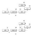
도 7은 도 3의 회전변환모듈의 작동과정을 예시한 도면이고, 도 8은 도 1의 코드리스 블라인드 장치의 제어방식을 예시한 모식도이며, 도 9 내지 도 12는 도 1의 코드리스 블라인드 장치의 작동과정을 예시한 도면이다.7 is a view illustrating an operation process of the rotation conversion module of Figure 3, Figure 8 is a schematic diagram illustrating a control method of the cordless blind device of Figure 1, Figures 9 to 12 is the operation of the cordless blind device of FIG. A diagram illustrating the process.
도 7을 참조하면, 회전변환모듈(420)은 태양기어와 유성기어의 조합을 통해 양방향 회전을 매우 효과적으로 전달할 수 있다. 예를 들어, 도 7의 (a)와 같이 축부재(430)로부터 회전변환모듈(420) 방향(A방향)으로 구동력이 전달될 수 있다. 축부재(430)는 도 3 및 도 5에 도시된 바와 같이 제1고정부(431)를 통해 제2회전블록(41)에 결합되고, 제2고정부(432)를 통해 제2회전요소(422)의 연결축(422c)에 결합되므로, 제2회전블록(41)의 회전축으로 기능하여 권취롤(10)과 함께 회전되는 제2회전블록(41)의 회전력을 회전변환모듈(420)로 전달할 수 있다. 이와 같이 회전변환모듈(420)로 회전이 전달되면, 제2회전요소(422)의 제2회전판(422b)이 동일방향으로 회전하며 복수 개의 제2유성기어(422a)를 공전시킨다. 제2유성기어(422a)는 링기어부(424)의 내주면에 형성된 링기어(424a)와 치합되어 이동하므로 자전방향은 제2회전판(422b)의 공전방향과 반대로 역전된다. 이로 인해 제2유성기어(422a)에 치합된 제2태양기어(423c)는 제2유성기어(422a)의 자전방향과 역방향으로 회전하게 된다. 제2태양기어(423c)는 제1회전판(423b)과 일체로 형성되어 있으므로, 제1회전판(423b)은 제2태양기어(423c)의 회전방향과 동일방향으로 회전하며 제1유성기어(423a)를 공전시키며, 제2유성기어(422a)는 링기어(424a)와 치합되어 이동하므로 자전방향은 제1회전판(423b)의 공전방향과 반대로 역전된다. 이로 인해 결국, 제1유성기어(423a)에 치합된 제1태양기어(421a)는 제1유성기어(423a)의 자전방향과 역방향으로 회전하며 구동모터(410)로 회전을 전달하게 된다.Referring to FIG. 7, the
이와 같이 제2회전요소(422), 회전매개유닛(423), 제1회전요소(421)를 거치며 권취롤(10)로부터 구동모터(410)의 방향(A방향)으로 회전 구동력을 효과적으로 전달할 수 있다. 이때 각 유성기어의 기어비, 각 태양기어의 기어비, 링기어의 기어비 등에 의해 적어도 한 번 이상 회전비가 바뀌게 된다. 따라서 회전속도를 바꾸어 전달할 수 있으며, 예를 들어, 축부재(430)의 회전수보다 많은 수의 회전비로 구동모터(410)의 회전속도를 증가시켜 구동할 수 있다.In this way, the rotational driving force can be effectively transmitted from the take-
한편, 도 도 7의 (b)와 같이 구동모터(410)로부터 회전변환모듈(420) 방향(B방향)으로 구동력이 전달될 수도 있다. 전술한 회전과정의 역과정을 통해 역시 반대방향으로도 구동력을 매우 효과적으로 전달할 수 있다. 구동모터(410)가 회전하면, 제1태양기어(421a)가 동일방향으로 회전하고, 제1태양기어(421a)에 치합된 제1유성기어(423a)는 그 역방향으로 자전하며 자전방향과 역방향으로 링기어(424a)를 따라 공전하게 된다. 따라서 제1유성기어(423a)와 결합된 제1회전판(423b) 역시 제1유성기어(423a)의 공전방향과 동일방향으로 회전하며 제2태양기어(423c)를 회전시키게 된다. 제2태양기어(423c)는 제2유성기어(422a)와 치합되어 있으므로 제2유성기어(422a)는 제2태양기어(423c)의 회전방향과 역방향으로 자전하며 자전방향의 역방향으로 링기어(424a)를 따라 공전하게 된다. 따라서 제2유성기어(422a)와 결합된 제2회전판(422b)은 제2유성기어(422a)의 공전방향과 동일방향으로 회전하며 제2회전판(422b)에 연결된 축부재(430)를 회전시키게 된다. 이를 통해 결국, 제2회전판(422b)과 동일방향의 회전을 축부재(430)를 통해서 도 3 및 도 4의 제2회전블록(42)과 권취롤(10)에 전달하게 된다. 이와 같이 제1회전요소(421), 회전매개유닛(423), 제2회전요소(422)를 거치며 구동모터(410)로부터 권취롤(10)의 방향(B방향)으로 역시 회전 구동력을 효과적으로 전달할 수 있다. 이때 각 유성기어의 기어비, 각 태양기어의 기어비, 링기어의 기어비 등에 의해 적어도 한 번 이상 회전비가 바뀌어 회전속도를 바꾸어 전달할 수 있으며, 예를 들어, 구동모터(410)의 회전수보다 적은 수의 회전비로 권취롤(10)의 회전속도를 감소시켜 구동할 수 있다.Meanwhile, as shown in FIG. 7B, the driving force may be transmitted from the driving
이와 같이 회전변환모듈(420)의 양방향 회전전달(즉, 전술한 A 및 B 방향의 회전 구동력의 전달)은 권취롤(10)로부터 구동모터(410) 측으로, 또는 구동모터(410) 측으로부터 권취롤(10) 측으로 자유롭게 바뀔 수 있으며, 각 구동력의 전달시 전달되는 회전방향 자체도 권취롤(10)이 권출되는 방향의 회전이나 권취되는 방향의 회전을 가리지 않고 어느 방향의 회전이나 효과적으로 전술한 A방향 또는 B방향으로 자유롭게 전달할 수 있다. 이와 같은 회전변환모듈(420)의 회전전달 동작을 이용하여 코드리스 블라인드 장치를 전술한 바와 같이 적절한 시점에 자동으로 동작하도록 매우 편리하게 제어할 수 있다.As described above, the bidirectional rotational transmission of the rotation conversion module 420 (that is, the transmission of the rotational driving force in the A and B directions described above) is wound from the take-
도 8의 (a)를 참조하면, 권취롤(10)로부터, 회전변환모듈(420)을 통해, 구동모터(410)에 회전력을 전달할 수 있다. 이때 전술한 바와 같이 사용자가 웨이트부재(도 1의 21참조)등으로 외력을 가하여 힘의 균형을 해제하고 권취롤(10)을 회전시킬 수 있다. 회전방향은 권취롤(10)을 권취하거나 권출하는 방향 어느 쪽으로도 가능하며 이러한 회전을 전술한 회전변환모듈(420)의 구동력 전달구조를 이용하여 권취롤(10)로부터 구동모터(410)를 향하는 방향(A방향)으로 전달할 수 있다. 이와 같이 구동모터(410)에 회전력이 전달되면, 구동모터(410)의 회전동작을 엔코더(411)로 감지할 수 있다. 엔코더(411)는 회전동작의 감지신호를 제어모듈(412)로 전송하고 제어모듈(412)은 엔코더(411)의 감지신호를 통해 회전동작을 인식할 수 있다. 이와 같이 회전동작이 인식되면 제어모듈(412)은 도 8의 (b)와 같이 구동모터(410)에 제어신호(S)를 전송하여 구동모터(410)를 구동시키게 된다. 따라서, 구동모터(410)는 권취롤(10)로부터 구동력을 전달받아 종속 회전하는 수동 회전체에서, 자동 회전하는 능동 회전체로 바뀌게 된다. 이때 구동력의 전달방향은 구동모터(410)로부터 전술한 회전변환모듈(420)의 전달구조를 통해 권취롤(10)을 향하는 방향(B방향)으로 역전되며 구동력에 의한 회전방향은 권취롤(10)이 최초 회전한 방향과 동일한 방향으로 형성된다. 따라서, 권취롤(10)은 구동모터(410)의 구동력에 의해 최초 회전한 방향으로 회전하며 스크린부재(도 1의 20참조)를 감거나 풀게 된다. 이와 같은 방식으로 적절한 시점에 코드리스 블라인드 장치가 자동으로 작동되도록 제어할 수 있다.Referring to FIG. 8 (a), the rotational force may be transmitted from the winding
즉, 권취롤(10) 및 구동모터(410) 중 적어도 어느 하나의 회전을 감지하는 엔코더(411)와 엔코더(411)로부터 회전동작이 감지되면 구동모터(410)를 구동하는 제어모듈(412)를 이용하여 코드리스 블라인드 장치를 자동으로 제어할 수 있다. 본 발명의 실시예에서는 구동모터(410) 측에 엔코더(411)가 연결되어 구동모터(410)의 회전을 감지하는 형태를 설명하였으나, 권취롤(10)의 회전을 직접 감지하는 엔코더를 설치하여 권취롤(10)의 회전을 엔코더로 감지하고 구동모터(410)를 구동하는 것도 가능하다. 또한, 권취롤(10) 및 구동모터(410)는 회전비는 다르더라도 서로 연결되어 함께 회전하도록 되어 있는바 권취롤(10), 구동모터(410), 또는 그 사이를 연결하거나 그와 함께 회전하는 회전체[회전변환모듈(420), 제2회전블록(41), 제1회전블록(31), 축부재(430) 등] 중 적어도 어느 하나의 회전을 엔코더로 감지하고 적정회전수가 감지되면 구동모터(410)를 구동시켜 자동으로 장치를 조작하는 것도 얼마든지 가능하다. 이러한 경우, 제어모듈(412)은 구동모터(410)의 동작 중 순간 부하가 증가하면 구동모터(410)의 구동을 정지할 수 있다. 즉, 스크린부재(20)가 완전히 권출되거나, 완전히 권취되어 회전이 제한되면 구동모터(410)의 부하가 증가될 수 있으므로 이와 같이 구동모터(410)의 부하가 증가하면 구동모터(410)의 구동을 정지하는 제어를 할 수 있다. 또한, 엔코더(411) 등을 이용하지 않고 구동모터(410)의 회전으로 내부에 기전력이 발생하면 이를 신호로 구동모터(410)를 구동하여 회전 구동시킬 수 있다. 예를 들어, 센서리스 제어방식으로 구동모터(410)의 회전속도를 감지하고 구동모터(410)를 동작시키거나 과부하를 감지하여 구동을 정지시키는 등의 제어를 하는 것도 얼마든지 가능하다.That is, the
이를 통해, 도 9 내지 도 12에 예시된 바와 같은 방식으로 코드리스 블라인드 장치(1)를 매우 편리하게 작동시킬 수 있다. 코드리스 블라인드 장치(1)는 도 9에 도시된 바와 같이 외력이 없는 경우에는 웨이트부재(21)가 스크린부재(20)가 권출되는 제1방향으로 인가하는 토크(T1)와, 토션스프링(30)이 스크린부재(20)가 권취되는 제2방향으로 인가하는 토크(T2)가 쌍으로 생성되며 어느 정도 균형을 이룰 수 있다. 그러나 전술한 바와 같이 이러한 토크의 쌍은 서로 비례적으로 증감되나 상호 크기는 완전히 일치하지 않을 수 있는바, 권취롤(10)에 연결된 회전변환모듈(420)과 구동모터(410)의 저항력으로 차이를 상쇄시켜 전체적으로 힘의 평형을 유지할 수 있다. 즉, 전술한 바와 같이 회전변환모듈(420)과 구동모터(410)의 저항력을 힘의 평형을 이루는 요소로 설계에 반영하여 서로 반대방향으로 형성되는 토크의 쌍과, 저항력이 평형을 이루어 스크린부재(20)가 정지한 채로 유지되도록 할 수 있다.This makes it possible to operate the cordless
이러한 상태에서 도 10에 도시된 바와 같이 웨이트부재(21) 등에 외력을 가하여 권취롤(10)을 회전시킬 수 있다. 약간의 외력으로도 힘의 균형상태를 해제할 수 있고, 이를 통해 일 방향의 토크를 일시적으로 증가시켜 권취롤(10)을 해당 토크의 방향으로 회전시킬 수 있다. 예를 들어, 도시된 바와 같이 웨이트부재(21)에 상승력을 가하여 스크린부재(20)를 권취하는 방향으로 권취롤(10)을 간단히 회전시킬 수 있다. 전술한 바와 같이 토션스프링(30)이 인가하는 토크는 회전변환모듈(420)의 마찰저항력(전술한 기어 들의 회전 접촉 등을 포함하는 기계적 마찰저항일 수 있음)과 구동모터(410)의 회생저항력(모터의 회전에 의해 발생하는 유도전류에 의한 전자기적 저항력을 말함)의 합력보다는 크게 설정되어 외력에 의해 균형이 깨지고 이와 같이 회전이 시작되면, 최소한 이러한 저항력은 이기며 회전이 가능하게 형성할 수 있다. 그러나, 이러한 저항력은 토션스프링(30)이 권취방향으로 인가하는 토크와, 웨이트부재(21)가 권출방향으로 인가하는 서로 반대방향의 토크 쌍의 차이를 상쇄할 수 있는 크기로 설정되어 있어 외력이 제거되면 즉시 힘의 균형을 이루게 되므로, 스크린부재(20)를 끝까지 권취하기 위해서는 약간의 외력이라도 지속적으로 제공되어야 할 수 있다.In this state, as illustrated in FIG. 10, the winding
이러한 문제는 전술한 바와 같은 자동 제어를 통해 매우 효과적으로 해결된다. 즉, 도 10에 도시된 바와 같이 권취롤(10)이 회전하면 회전변환모듈(420)을 통해 구동모터(410)를 향하는 방향(A방향)으로 구동력이 전달되고, 엔코더(411)를 통해 회전동작을 감지할 수 있다. 따라서 회전동작이 감지되면 전술한 바와 같이 제어모듈(412)로 구동모터(410)를 구동하여 도 11에 도시된 바와 같이, 구동력의 전달방향을 구동모터(410)에서 권취롤(10)을 향하는 방향(B방향)으로 역전시킬 수 있다. 이때 회전방향은 최초 권취롤(10)이 회전한 방향 그대로 유지되므로, 도시된 바와 같이 구동모터(410)의 구동력으로 권취롤(10)을 원래 의도한 방향으로 회전시키며 코드리스 블라인드 장치(1)의 스크린부재(20)를 자동으로 조작할 수 있다. 즉, 도 10에 도시된 바와 같이 사용자가 약간의 외력을 가하여 권취롤(10)을 시동하면, 구동력이 구동모터(410)로 전달되고, 이를 감지한 제어모듈(412)이 구동모터(410)를 동작시켜, 도 11에 도시된 바와 같이 구동모터(410)의 회전력으로 스크린부재(20)를 자동으로 권취할 수 있다. 이와 같이 자동으로 권취되는 코드리스 블라인드 장치(1)는 도 12에 도시된 바와 같이 스크린부재(20)가 완전히 권취되면, 전술한 구동모터(410)의 부하를 감지하는 제어 등을 통해 구동모터(410)를 정지하고 외력이 제거된 상태에서 다시 힘의 균형을 이루어 해당 위치에서 권취롤(10)을 정지상태로 유지할 수 있다.This problem is very effectively solved through the automatic control as described above. That is, as shown in FIG. 10, when the winding
이와 같이 사용자의 수동 제어를 일종의 동작신호로 하여 스크린부재(20)를 자동으로 권취하거나 권출하는 제어를 할 수 있다. 이러한 자동 제어를 통해 보다 편리하게 코드리스 블라인드 장치(1)를 조작할 수 있다. 또한, 배터리 등의 사용시간이 도과하여 자동 동작이 되지 않더라도, 약간의 외력을 가하여 힘의 균형을 해제할 수 있으므로 코드리스 블라인드 장치(1)를 수동 또는 반자동 방식으로도 얼마든지 자유롭게 조작할 수 있다. 또한, 필요한 경우에는 리모컨 등으로 구동모터(410)를 원거리에서 자동으로 작동시킴으로써 수동 제어 등의 동작신호 없이도 완전 자동방식으로 코드리스 블라인드 장치(1)를 편리하게 조작할 수 있다.In this way, the user's manual control as a kind of operation signal can be controlled to automatically wound or unwind the
이상 첨부된 도면을 참조하여 본 발명의 실시예를 설명하였지만, 본 발명이 속하는 기술분야에서 통상의 지식을 가진 자는 본 발명이 그 기술적 사상이나 필수적인 특징을 변경하지 않고서 다른 구체적인 형태로 실시될 수 있다는 것을 이해할 수 있을 것이다. 그러므로 이상에서 기술한 실시예들은 모든 면에서 예시적인 것이며 한정적이 아닌 것으로 이해해야만 한다.Although embodiments of the present invention have been described above with reference to the accompanying drawings, those skilled in the art to which the present invention pertains may implement the present invention in other specific forms without changing the technical spirit or essential features thereof. I can understand that. Therefore, it should be understood that the embodiments described above are exemplary in all respects and not restrictive.
1: 코드리스 블라인드 장치 10: 권취롤
10a: 가이드돌기 11: 프레임
11a: 수평프레임 11b: 수직프레임
11c: 연결부 12: 배터리박스
20: 스크린부재 21: 웨이트바
30: 토션스프링 31: 제1회전블록
31a: 결합홈 32: 제1고정블록
40: 회전변환구동부 41: 제2회전블록
41a: 결합돌기 41b: 축결합부
42: 제2고정블록 43: 하우징
110, 120: 회전링 410: 구동모터
411: 엔코더 412: 제어모듈
420: 회전변환모듈 421: 제1회전요소
421a: 제1태양기어 422: 제2회전요소
422a: 제2유성기어 422b: 제2회전판
422c: 연결축 423: 회전매개유닛
423a: 제1유성기어 423b: 제1회전판
423c: 제2태양기어 424: 링기어부
424a: 링기어 430: 축부재
431: 제1고정부 432: 제2고정부
A, B: 구동력 전달방향1: cordless blind device 10: winding roll
10a: Guide protrusion 11: frame
11a:
11c: connection 12: battery box
20: screen member 21: weight bar
30: torsion spring 31: first rotating block
31a: coupling groove 32: first fixing block
40: rotation conversion drive portion 41: the second rotation block
41a: engaging
42: second fixing block 43: housing
110, 120: rotation ring 410: drive motor
411: encoder 412: control module
420: rotation conversion module 421: first rotating element
421a: first sun gear 422: second rotating element
422a: second
422c: connecting shaft 423: rotation media unit
423a: first
423c: second sun gear 424: ring gear part
424a: ring gear 430: shaft member
431: First Government 432: Second Government
A, B: driving force transmission direction
Claims (10)
상기 권취롤에 권취되거나 권출되는 스크린부재;
상기 권취롤에 회전 구동력을 제공하여 상기 스크린부재를 권취하거나 권출하는 구동모터;
상기 스크린부재 하단에 연결되어 중력에 의해 상기 권취롤에 상기 스크린부재가 권출되는 제1방향으로 토크를 인가하는 웨이트부재;
상기 권취롤에 탄성력을 가하여 상기 스크린부재가 권취되는 제2방향으로 토크를 인가하는 토션스프링; 및
상기 구동모터와 상기 권취롤 사이에 결합되며, 상기 구동모터가 제공하는 회전 구동력을 상기 권취롤에 전달하거나, 상기 토션스프링이 상기 권취롤에 제공하는 토크를 상기 구동모터로 전달하여, 양방향으로 동력을 전달하는 회전변환모듈을 포함하며,
상기 구동모터가 구동력을 발생시키지 않는 상태에서, 상기 토션스프링에 의해 인가된 토크와, 상기 웨이트부재에 의해 인가된 토크와, 상기 회전변환모듈과 상기 구동모터에 의한 저항력이 평형을 이루어 상기 스크린부재가 정지한 채로 유지되고,
상기 웨이트부재에 상방 또는 하방으로 외력이 작용하면, 힘의 평형이 깨져 상기 스크린부재가 상기 권취롤에 권취되거나 권출되고,
상기 토션스프링이 인가하는 토크는 상기 회전변환모듈의 마찰저항력과 상기 구동모터의 회생저항력의 합력보다 크게 설정된 코드리스 블라인드 장치.A winding roll coupled to the rotating shaft;
A screen member wound or unwound on the winding roll;
A driving motor for winding or unwinding the screen member by providing a rotational driving force to the winding roll;
A weight member connected to a lower end of the screen member to apply torque to the take-up roll in a first direction by which the screen member is unwound by gravity;
A torsion spring that applies an elastic force to the winding roll to apply torque in a second direction in which the screen member is wound; And
Coupled between the drive motor and the take-up roll, transfer the rotational driving force provided by the drive motor to the take-up roll, or transfer the torque provided by the torsion spring to the take-up roll to the drive motor, power in both directions It includes a rotation conversion module for transmitting,
In a state where the driving motor does not generate a driving force, the torque applied by the torsion spring, the torque applied by the weight member, and the resistance by the rotation conversion module and the driving motor are balanced to form the screen member. Remains stationary,
When an external force acts upward or downward on the weight member, the balance of force is broken so that the screen member is wound or unwound on the take-up roll,
And a torque applied by the torsion spring is greater than a sum of the frictional resistance of the rotation conversion module and the regenerative resistance of the drive motor.
상기 회전변환모듈은, 상기 구동모터에 연결되어 함께 회전하는 제1회전요소와, 상기 권취롤에 연결되어 회전하는 제2회전요소와, 상기 제1회전요소와 상기 제2회전요소 사이에 개재되어 동력을 전달하는 회전매개유닛을 포함하는 코드리스 블라인드 장치.The method of claim 1,
The rotation conversion module is interposed between the first rotating element connected to the drive motor to rotate together, the second rotating element connected to the winding roll to rotate, and the first rotating element and the second rotating element. Cordless blind device comprising a rotation media unit for transmitting power.
상기 제1회전요소와 상기 제2회전요소는 회전중심이 동일 축상에 위치하고, 상기 회전매개유닛은 상기 제1회전요소의 회전속도를 감속하여 상기 제2회전요소에 전달하는 코드리스 블라인드 장치.The method of claim 3,
Cordless blind apparatus for the first rotary element and the second rotary element is located on the same axis of rotation, the rotation medium unit to reduce the rotational speed of the first rotating element to the second rotating element.
상기 제1회전요소는 제1태양기어를 포함하고,
상기 회전매개유닛은 상기 제1태양기어 둘레를 공전하는 복수 개의 제1유성기어와, 상기 제1유성기어의 회전축이 결합된 제1회전판과, 상기 제1유성기어가 결합된 반대면의 상기 제1회전판에 결합된 제2태양기어를 포함하고,
상기 제2회전요소는 상기 제2태양기어 둘레를 공전하는 복수 개의 제2유성기어와, 상기 제2유성기어의 회전축이 결합된 제2회전판을 포함하는 코드리스 블라인드 장치.The method of claim 3,
The first rotating element includes a first sun gear,
The rotation mediating unit includes a plurality of first planetary gears revolving around the first sun gear, a first rotating plate to which a rotation shaft of the first planetary gear is coupled, and the first surface of the opposite side to which the first planetary gear is coupled. A second sun gear coupled to the first rotating plate,
The second rotating element includes a plurality of second planetary gears revolving around the second sun gear, and a second rotating plate coupled to the rotation axis of the second planetary gear.
상기 제1유성기어와 상기 제2유성기어가 동시에 내접하는 링기어를 더 포함하는 코드리스 블라인드 장치.The method of claim 5,
And a ring gear in which the first planetary gear and the second planetary gear are inscribed at the same time.
외주면이 상기 권취롤 내측에 결합되어 함께 회전하며, 회전축이 상기 제2회전요소에 결합된 회전블록을 더 포함하는 코드리스 블라인드 장치.The method of claim 5,
An outer circumferential surface is coupled to the inside of the take-up roll to rotate together, the cordless blind device further comprises a rotary block coupled to the second rotating element.
상기 권취롤 및 구동모터 중 적어도 어느 하나의 회전을 감지하는 엔코더, 및
상기 엔코더로부터 회전동작이 감지되면 상기 구동모터를 구동하는 제어모듈을 더 포함하는 코드리스 블라인드 장치.The method of claim 1,
An encoder for detecting rotation of at least one of the winding roll and the driving motor, and
And a control module for driving the driving motor when a rotational motion is detected from the encoder.
상기 제어모듈은, 상기 구동모터의 동작 중 순간 부하가 증가하면 상기 구동모터의 구동을 정지하는 코드리스 블라인드 장치.The method of claim 8,
The control module, the cordless blind device for stopping the drive of the drive motor when the momentary load increases during the operation of the drive motor.
상기 구동모터를 제어하되, 상기 구동모터에 기전력이 발생하면 상기 구동모터를 회전 구동하는 제어모듈을 더 포함하는 코드리스 블라인드 장치.The method of claim 1,
And a control module for controlling the driving motor and rotating the driving motor when an electromotive force is generated in the driving motor.
Priority Applications (7)
| Application Number | Priority Date | Filing Date | Title |
|---|---|---|---|
| KR1020180002823A KR102051896B1 (en) | 2018-01-09 | 2018-01-09 | Cordless blind apparatus |
| EP19738594.1A EP3739162A4 (en) | 2018-01-09 | 2019-01-04 | CORDLESS BLIND DEVICE |
| US16/958,847 US11261659B2 (en) | 2018-01-09 | 2019-01-04 | Cordless blind device |
| CN201980007600.1A CN111566306B (en) | 2018-01-09 | 2019-01-04 | Wireless shutter device |
| PCT/KR2019/000163 WO2019139306A1 (en) | 2018-01-09 | 2019-01-04 | Cordless blind device |
| CA3088850A CA3088850C (en) | 2018-01-09 | 2019-01-04 | Cordless blind device |
| JP2020535570A JP6928212B2 (en) | 2018-01-09 | 2019-01-04 | Cordless blind device |
Applications Claiming Priority (1)
| Application Number | Priority Date | Filing Date | Title |
|---|---|---|---|
| KR1020180002823A KR102051896B1 (en) | 2018-01-09 | 2018-01-09 | Cordless blind apparatus |
Publications (2)
| Publication Number | Publication Date |
|---|---|
| KR20190084728A KR20190084728A (en) | 2019-07-17 |
| KR102051896B1 true KR102051896B1 (en) | 2019-12-06 |
Family
ID=67219068
Family Applications (1)
| Application Number | Title | Priority Date | Filing Date |
|---|---|---|---|
| KR1020180002823A Active KR102051896B1 (en) | 2018-01-09 | 2018-01-09 | Cordless blind apparatus |
Country Status (7)
| Country | Link |
|---|---|
| US (1) | US11261659B2 (en) |
| EP (1) | EP3739162A4 (en) |
| JP (1) | JP6928212B2 (en) |
| KR (1) | KR102051896B1 (en) |
| CN (1) | CN111566306B (en) |
| CA (1) | CA3088850C (en) |
| WO (1) | WO2019139306A1 (en) |
Cited By (3)
| Publication number | Priority date | Publication date | Assignee | Title |
|---|---|---|---|---|
| WO2021117945A1 (en) * | 2019-12-12 | 2021-06-17 | 박우주 | Combined manual and electric blinds driving device |
| KR20210146075A (en) | 2020-05-26 | 2021-12-03 | 삼성에스디에스 주식회사 | System and method for managing data state based on blockchain |
| KR20220080247A (en) * | 2020-12-07 | 2022-06-14 | 아이오티테크 주식회사 | Blind driving device using electric and manual mode |
Families Citing this family (13)
| Publication number | Priority date | Publication date | Assignee | Title |
|---|---|---|---|---|
| CN110409985B (en) * | 2019-09-10 | 2024-04-26 | 襄阳市思想机电科技有限公司 | Pulley system of one-way door |
| KR102449141B1 (en) * | 2020-02-24 | 2022-09-30 | (주)한국윈텍 | Cordless blind device with tangling recovery function |
| US11905758B2 (en) | 2020-07-02 | 2024-02-20 | Springs Window Fashions, Llc | Roller shade assembly |
| CN116635639A (en) * | 2020-11-18 | 2023-08-22 | 三星电子株式会社 | Electronics including torque structures |
| CA3111944C (en) * | 2020-12-30 | 2023-04-25 | Mingyang Windeco Technology Corporation | Constant force multiple spring curtain winding system |
| JP2023007751A (en) * | 2021-07-02 | 2023-01-19 | パナソニックIpマネジメント株式会社 | Electric switching body controller, electric switch system, program |
| WO2024174691A1 (en) * | 2023-02-21 | 2024-08-29 | 厦门多士龙智能科技有限公司 | Roller shutter curtain |
| CN116084819A (en) * | 2023-03-06 | 2023-05-09 | 浙江依雅诺遮阳科技有限公司 | A manual electric double control curtain |
| US20240309700A1 (en) * | 2023-03-13 | 2024-09-19 | Tser Wen Chou | Touch-controlled window covering system |
| FR3152163B1 (en) | 2023-08-14 | 2025-08-22 | Somfy Activites Sa | Electromechanical actuator and occultation device comprising such an electromechanical actuator |
| FR3152164B1 (en) * | 2023-08-14 | 2025-08-22 | Somfy Activites Sa | Electromechanical actuator and occultation device comprising such an electromechanical actuator |
| KR200499083Y1 (en) * | 2023-10-31 | 2025-04-28 | 쿠오, 훼이 아이 | Resistance-free balance control system for curtains |
| CN119195631B (en) * | 2024-11-13 | 2025-03-07 | 厦门东生荣科技股份有限公司 | Power system of rolling curtain device and rolling curtain device |
Citations (1)
| Publication number | Priority date | Publication date | Assignee | Title |
|---|---|---|---|---|
| JP2006274538A (en) * | 2005-03-28 | 2006-10-12 | Sanwa Shutter Corp | Electric shutter control device |
Family Cites Families (23)
| Publication number | Priority date | Publication date | Assignee | Title |
|---|---|---|---|---|
| JPS5948999U (en) * | 1982-09-24 | 1984-03-31 | メタコ企業株式会社 | Winding braking device for roll screens, etc. |
| JPH0913856A (en) * | 1995-06-30 | 1997-01-14 | Toso Co Ltd | Manual electric roll blind |
| JP3994560B2 (en) * | 1998-11-29 | 2007-10-24 | アイシン精機株式会社 | Shutter drive device |
| US6571853B1 (en) * | 2000-07-06 | 2003-06-03 | Newell Window Furnishings, Inc. | Cordless blind having variable resistance to movement |
| JP2002227556A (en) * | 2001-01-30 | 2002-08-14 | Jumbo Surplus Corp | Rolling up mechanism for cordless venetian blind |
| CN2585960Y (en) * | 2002-11-07 | 2003-11-12 | 浙江特种电机有限公司 | Tubular shutter driving gear |
| JP2004257015A (en) * | 2003-02-24 | 2004-09-16 | Hayashiguchi Kogyo Kk | Rolling screen device |
| TWI465636B (en) * | 2007-03-30 | 2014-12-21 | Hunter Douglas | A spring motor, a spring motor and drag brake combination, and a covering system for covering an architectural |
| CN101182754A (en) * | 2007-12-14 | 2008-05-21 | 周文庆 | Novel dynamoelectric concealed mesh window |
| CN101498194A (en) | 2008-02-03 | 2009-08-05 | 郑立铭 | Non-pull cord rolling curtain |
| US9194179B2 (en) * | 2010-02-23 | 2015-11-24 | Qmotion Incorporated | Motorized shade with the transmission wire passing through the support shaft |
| US8368328B2 (en) | 2010-02-23 | 2013-02-05 | Homerun Holdings Corporation | Method for operating a motorized roller shade |
| US9249623B2 (en) * | 2010-02-23 | 2016-02-02 | Qmotion Incorporated | Low-power architectural covering |
| WO2012125423A1 (en) * | 2011-03-11 | 2012-09-20 | Lutron Electronics Co., Inc. | Low power radio frequency receiver |
| FR3004745B3 (en) * | 2013-04-17 | 2017-01-27 | Somfy Sas | ROTATIONAL DRIVE SYSTEM FOR ROLLER DRUM, ROLL-UP CLOSURE SCREEN AND STEERING METHOD |
| CA2877254C (en) * | 2015-01-09 | 2016-01-05 | Les Mcgowan | Roller blind for a window that affords positioning of a screen at a stable height by means of a frictional interface |
| TWI583858B (en) * | 2015-01-20 | 2017-05-21 | 德侑股份有限公司 | Window shade and control system thereof |
| KR200480955Y1 (en) | 2015-03-09 | 2016-07-29 | 문제선 | Roll blind |
| US20170081914A1 (en) * | 2015-09-23 | 2017-03-23 | Bao Song Precision Industry Co., Ltd. | Control device for cordless blind with willful stop |
| KR101774567B1 (en) | 2016-11-21 | 2017-09-05 | (주)한국윈텍 | Cordless blind apparatus |
| CN206608078U (en) * | 2017-03-29 | 2017-11-03 | 张伯仁 | A kind of electric and hand roller shutter type closed lorry body door |
| KR101899133B1 (en) * | 2017-08-10 | 2018-09-17 | (주)한국윈텍 | Cordless blind apparatus |
| KR102058096B1 (en) * | 2018-01-08 | 2019-12-20 | (주)한국윈텍 | Cordless blind apparatus capable of being driven by outer driving power |
-
2018
- 2018-01-09 KR KR1020180002823A patent/KR102051896B1/en active Active
-
2019
- 2019-01-04 WO PCT/KR2019/000163 patent/WO2019139306A1/en not_active Ceased
- 2019-01-04 EP EP19738594.1A patent/EP3739162A4/en not_active Withdrawn
- 2019-01-04 CA CA3088850A patent/CA3088850C/en active Active
- 2019-01-04 CN CN201980007600.1A patent/CN111566306B/en active Active
- 2019-01-04 JP JP2020535570A patent/JP6928212B2/en active Active
- 2019-01-04 US US16/958,847 patent/US11261659B2/en active Active
Patent Citations (1)
| Publication number | Priority date | Publication date | Assignee | Title |
|---|---|---|---|---|
| JP2006274538A (en) * | 2005-03-28 | 2006-10-12 | Sanwa Shutter Corp | Electric shutter control device |
Cited By (4)
| Publication number | Priority date | Publication date | Assignee | Title |
|---|---|---|---|---|
| WO2021117945A1 (en) * | 2019-12-12 | 2021-06-17 | 박우주 | Combined manual and electric blinds driving device |
| KR20210146075A (en) | 2020-05-26 | 2021-12-03 | 삼성에스디에스 주식회사 | System and method for managing data state based on blockchain |
| KR20220080247A (en) * | 2020-12-07 | 2022-06-14 | 아이오티테크 주식회사 | Blind driving device using electric and manual mode |
| KR102646836B1 (en) | 2020-12-07 | 2024-03-12 | 아이오티테크 주식회사 | Blind driving device using electric and manual mode |
Also Published As
| Publication number | Publication date |
|---|---|
| JP6928212B2 (en) | 2021-09-01 |
| CN111566306A (en) | 2020-08-21 |
| CA3088850A1 (en) | 2019-07-18 |
| WO2019139306A1 (en) | 2019-07-18 |
| CA3088850C (en) | 2022-10-04 |
| KR20190084728A (en) | 2019-07-17 |
| JP2021509161A (en) | 2021-03-18 |
| EP3739162A1 (en) | 2020-11-18 |
| EP3739162A4 (en) | 2021-10-27 |
| US11261659B2 (en) | 2022-03-01 |
| CN111566306B (en) | 2022-04-01 |
| US20210032931A1 (en) | 2021-02-04 |
Similar Documents
| Publication | Publication Date | Title |
|---|---|---|
| KR102051896B1 (en) | Cordless blind apparatus | |
| US10975619B2 (en) | Methods and apparatus to control architectural opening covering assemblies | |
| US9152032B2 (en) | High efficiency motorized roller screen and method of operation | |
| KR102058096B1 (en) | Cordless blind apparatus capable of being driven by outer driving power | |
| GB2534083B (en) | Rail for an architectural covering | |
| CN107923220A (en) | Closing or sunshade home automation installation and the accumulator charging method of this equipment | |
| KR200439469Y1 (en) | Roll blinds | |
| CN101498194A (en) | Non-pull cord rolling curtain | |
| KR102449141B1 (en) | Cordless blind device with tangling recovery function | |
| CN214943865U (en) | Heat insulation curtain with adjustable transmittance | |
| KR101405777B1 (en) | Awning including loop coupling | |
| WO2020106207A1 (en) | Motorized window cover device with solar cells arranged at a wand, and a wand comprising solar cells | |
| KR102039012B1 (en) | Dual Blind | |
| CN223119837U (en) | Rolling curtain winding and unwinding device | |
| KR20010044566A (en) | Multi-roll blind apparatus | |
| WO2025229331A1 (en) | Retractable blind system | |
| KR200209616Y1 (en) | Power transmit apparatus for sunlight shutter |
Legal Events
| Date | Code | Title | Description |
|---|---|---|---|
| A201 | Request for examination | ||
| PA0109 | Patent application |
Patent event code: PA01091R01D Comment text: Patent Application Patent event date: 20180109 |
|
| PA0201 | Request for examination | ||
| E902 | Notification of reason for refusal | ||
| PE0902 | Notice of grounds for rejection |
Comment text: Notification of reason for refusal Patent event date: 20190524 Patent event code: PE09021S01D |
|
| PG1501 | Laying open of application | ||
| E701 | Decision to grant or registration of patent right | ||
| PE0701 | Decision of registration |
Patent event code: PE07011S01D Comment text: Decision to Grant Registration Patent event date: 20191127 |
|
| GRNT | Written decision to grant | ||
| PR0701 | Registration of establishment |
Comment text: Registration of Establishment Patent event date: 20191128 Patent event code: PR07011E01D |
|
| PR1002 | Payment of registration fee |
Payment date: 20191129 End annual number: 3 Start annual number: 1 |
|
| PG1601 | Publication of registration | ||
| FPAY | Annual fee payment |
Payment date: 20221101 Year of fee payment: 4 |
|
| PR1001 | Payment of annual fee |
Payment date: 20221101 Start annual number: 4 End annual number: 4 |
|
| PR1001 | Payment of annual fee |
Payment date: 20241029 Start annual number: 6 End annual number: 6 |