KR102051142B1 - System for managing dangerous driving index for vehicle and method therof - Google Patents
System for managing dangerous driving index for vehicle and method therof Download PDFInfo
- Publication number
- KR102051142B1 KR102051142B1 KR1020140072280A KR20140072280A KR102051142B1 KR 102051142 B1 KR102051142 B1 KR 102051142B1 KR 1020140072280 A KR1020140072280 A KR 1020140072280A KR 20140072280 A KR20140072280 A KR 20140072280A KR 102051142 B1 KR102051142 B1 KR 102051142B1
- Authority
- KR
- South Korea
- Prior art keywords
- vehicle
- load
- driving
- driver
- trajectory
- Prior art date
- Legal status (The legal status is an assumption and is not a legal conclusion. Google has not performed a legal analysis and makes no representation as to the accuracy of the status listed.)
- Active
Links
Images


Classifications
-
- B—PERFORMING OPERATIONS; TRANSPORTING
- B60—VEHICLES IN GENERAL
- B60W—CONJOINT CONTROL OF VEHICLE SUB-UNITS OF DIFFERENT TYPE OR DIFFERENT FUNCTION; CONTROL SYSTEMS SPECIALLY ADAPTED FOR HYBRID VEHICLES; ROAD VEHICLE DRIVE CONTROL SYSTEMS FOR PURPOSES NOT RELATED TO THE CONTROL OF A PARTICULAR SUB-UNIT
- B60W30/00—Purposes of road vehicle drive control systems not related to the control of a particular sub-unit, e.g. of systems using conjoint control of vehicle sub-units
- B60W30/14—Adaptive cruise control
-
- B—PERFORMING OPERATIONS; TRANSPORTING
- B60—VEHICLES IN GENERAL
- B60W—CONJOINT CONTROL OF VEHICLE SUB-UNITS OF DIFFERENT TYPE OR DIFFERENT FUNCTION; CONTROL SYSTEMS SPECIALLY ADAPTED FOR HYBRID VEHICLES; ROAD VEHICLE DRIVE CONTROL SYSTEMS FOR PURPOSES NOT RELATED TO THE CONTROL OF A PARTICULAR SUB-UNIT
- B60W40/00—Estimation or calculation of non-directly measurable driving parameters for road vehicle drive control systems not related to the control of a particular sub unit, e.g. by using mathematical models
- B60W40/08—Estimation or calculation of non-directly measurable driving parameters for road vehicle drive control systems not related to the control of a particular sub unit, e.g. by using mathematical models related to drivers or passengers
- B60W40/09—Driving style or behaviour
-
- B—PERFORMING OPERATIONS; TRANSPORTING
- B60—VEHICLES IN GENERAL
- B60W—CONJOINT CONTROL OF VEHICLE SUB-UNITS OF DIFFERENT TYPE OR DIFFERENT FUNCTION; CONTROL SYSTEMS SPECIALLY ADAPTED FOR HYBRID VEHICLES; ROAD VEHICLE DRIVE CONTROL SYSTEMS FOR PURPOSES NOT RELATED TO THE CONTROL OF A PARTICULAR SUB-UNIT
- B60W50/00—Details of control systems for road vehicle drive control not related to the control of a particular sub-unit, e.g. process diagnostic or vehicle driver interfaces
- B60W50/08—Interaction between the driver and the control system
- B60W50/14—Means for informing the driver, warning the driver or prompting a driver intervention
-
- B—PERFORMING OPERATIONS; TRANSPORTING
- B60—VEHICLES IN GENERAL
- B60W—CONJOINT CONTROL OF VEHICLE SUB-UNITS OF DIFFERENT TYPE OR DIFFERENT FUNCTION; CONTROL SYSTEMS SPECIALLY ADAPTED FOR HYBRID VEHICLES; ROAD VEHICLE DRIVE CONTROL SYSTEMS FOR PURPOSES NOT RELATED TO THE CONTROL OF A PARTICULAR SUB-UNIT
- B60W50/00—Details of control systems for road vehicle drive control not related to the control of a particular sub-unit, e.g. process diagnostic or vehicle driver interfaces
- B60W2050/0062—Adapting control system settings
- B60W2050/0075—Automatic parameter input, automatic initialising or calibrating means
-
- B—PERFORMING OPERATIONS; TRANSPORTING
- B60—VEHICLES IN GENERAL
- B60W—CONJOINT CONTROL OF VEHICLE SUB-UNITS OF DIFFERENT TYPE OR DIFFERENT FUNCTION; CONTROL SYSTEMS SPECIALLY ADAPTED FOR HYBRID VEHICLES; ROAD VEHICLE DRIVE CONTROL SYSTEMS FOR PURPOSES NOT RELATED TO THE CONTROL OF A PARTICULAR SUB-UNIT
- B60W50/00—Details of control systems for road vehicle drive control not related to the control of a particular sub-unit, e.g. process diagnostic or vehicle driver interfaces
- B60W50/08—Interaction between the driver and the control system
- B60W50/14—Means for informing the driver, warning the driver or prompting a driver intervention
- B60W2050/143—Alarm means
-
- B—PERFORMING OPERATIONS; TRANSPORTING
- B60—VEHICLES IN GENERAL
- B60W—CONJOINT CONTROL OF VEHICLE SUB-UNITS OF DIFFERENT TYPE OR DIFFERENT FUNCTION; CONTROL SYSTEMS SPECIALLY ADAPTED FOR HYBRID VEHICLES; ROAD VEHICLE DRIVE CONTROL SYSTEMS FOR PURPOSES NOT RELATED TO THE CONTROL OF A PARTICULAR SUB-UNIT
- B60W50/00—Details of control systems for road vehicle drive control not related to the control of a particular sub-unit, e.g. process diagnostic or vehicle driver interfaces
- B60W50/08—Interaction between the driver and the control system
- B60W50/14—Means for informing the driver, warning the driver or prompting a driver intervention
- B60W2050/146—Display means
-
- B—PERFORMING OPERATIONS; TRANSPORTING
- B60—VEHICLES IN GENERAL
- B60W—CONJOINT CONTROL OF VEHICLE SUB-UNITS OF DIFFERENT TYPE OR DIFFERENT FUNCTION; CONTROL SYSTEMS SPECIALLY ADAPTED FOR HYBRID VEHICLES; ROAD VEHICLE DRIVE CONTROL SYSTEMS FOR PURPOSES NOT RELATED TO THE CONTROL OF A PARTICULAR SUB-UNIT
- B60W2420/00—Indexing codes relating to the type of sensors based on the principle of their operation
- B60W2420/40—Photo, light or radio wave sensitive means, e.g. infrared sensors
- B60W2420/403—Image sensing, e.g. optical camera
-
- B—PERFORMING OPERATIONS; TRANSPORTING
- B60—VEHICLES IN GENERAL
- B60W—CONJOINT CONTROL OF VEHICLE SUB-UNITS OF DIFFERENT TYPE OR DIFFERENT FUNCTION; CONTROL SYSTEMS SPECIALLY ADAPTED FOR HYBRID VEHICLES; ROAD VEHICLE DRIVE CONTROL SYSTEMS FOR PURPOSES NOT RELATED TO THE CONTROL OF A PARTICULAR SUB-UNIT
- B60W2420/00—Indexing codes relating to the type of sensors based on the principle of their operation
- B60W2420/40—Photo, light or radio wave sensitive means, e.g. infrared sensors
- B60W2420/408—Radar; Laser, e.g. lidar
-
- B—PERFORMING OPERATIONS; TRANSPORTING
- B60—VEHICLES IN GENERAL
- B60W—CONJOINT CONTROL OF VEHICLE SUB-UNITS OF DIFFERENT TYPE OR DIFFERENT FUNCTION; CONTROL SYSTEMS SPECIALLY ADAPTED FOR HYBRID VEHICLES; ROAD VEHICLE DRIVE CONTROL SYSTEMS FOR PURPOSES NOT RELATED TO THE CONTROL OF A PARTICULAR SUB-UNIT
- B60W2420/00—Indexing codes relating to the type of sensors based on the principle of their operation
- B60W2420/54—Audio sensitive means, e.g. ultrasound
-
- B—PERFORMING OPERATIONS; TRANSPORTING
- B60—VEHICLES IN GENERAL
- B60W—CONJOINT CONTROL OF VEHICLE SUB-UNITS OF DIFFERENT TYPE OR DIFFERENT FUNCTION; CONTROL SYSTEMS SPECIALLY ADAPTED FOR HYBRID VEHICLES; ROAD VEHICLE DRIVE CONTROL SYSTEMS FOR PURPOSES NOT RELATED TO THE CONTROL OF A PARTICULAR SUB-UNIT
- B60W2520/00—Input parameters relating to overall vehicle dynamics
- B60W2520/10—Longitudinal speed
-
- B—PERFORMING OPERATIONS; TRANSPORTING
- B60—VEHICLES IN GENERAL
- B60W—CONJOINT CONTROL OF VEHICLE SUB-UNITS OF DIFFERENT TYPE OR DIFFERENT FUNCTION; CONTROL SYSTEMS SPECIALLY ADAPTED FOR HYBRID VEHICLES; ROAD VEHICLE DRIVE CONTROL SYSTEMS FOR PURPOSES NOT RELATED TO THE CONTROL OF A PARTICULAR SUB-UNIT
- B60W2520/00—Input parameters relating to overall vehicle dynamics
- B60W2520/14—Yaw
-
- B—PERFORMING OPERATIONS; TRANSPORTING
- B60—VEHICLES IN GENERAL
- B60W—CONJOINT CONTROL OF VEHICLE SUB-UNITS OF DIFFERENT TYPE OR DIFFERENT FUNCTION; CONTROL SYSTEMS SPECIALLY ADAPTED FOR HYBRID VEHICLES; ROAD VEHICLE DRIVE CONTROL SYSTEMS FOR PURPOSES NOT RELATED TO THE CONTROL OF A PARTICULAR SUB-UNIT
- B60W2520/00—Input parameters relating to overall vehicle dynamics
- B60W2520/28—Wheel speed
-
- B—PERFORMING OPERATIONS; TRANSPORTING
- B60—VEHICLES IN GENERAL
- B60W—CONJOINT CONTROL OF VEHICLE SUB-UNITS OF DIFFERENT TYPE OR DIFFERENT FUNCTION; CONTROL SYSTEMS SPECIALLY ADAPTED FOR HYBRID VEHICLES; ROAD VEHICLE DRIVE CONTROL SYSTEMS FOR PURPOSES NOT RELATED TO THE CONTROL OF A PARTICULAR SUB-UNIT
- B60W2540/00—Input parameters relating to occupants
- B60W2540/18—Steering angle
-
- B—PERFORMING OPERATIONS; TRANSPORTING
- B60—VEHICLES IN GENERAL
- B60W—CONJOINT CONTROL OF VEHICLE SUB-UNITS OF DIFFERENT TYPE OR DIFFERENT FUNCTION; CONTROL SYSTEMS SPECIALLY ADAPTED FOR HYBRID VEHICLES; ROAD VEHICLE DRIVE CONTROL SYSTEMS FOR PURPOSES NOT RELATED TO THE CONTROL OF A PARTICULAR SUB-UNIT
- B60W2554/00—Input parameters relating to objects
- B60W2554/40—Dynamic objects, e.g. animals, windblown objects
- B60W2554/408—Traffic behavior, e.g. swarm
-
- B—PERFORMING OPERATIONS; TRANSPORTING
- B60—VEHICLES IN GENERAL
- B60W—CONJOINT CONTROL OF VEHICLE SUB-UNITS OF DIFFERENT TYPE OR DIFFERENT FUNCTION; CONTROL SYSTEMS SPECIALLY ADAPTED FOR HYBRID VEHICLES; ROAD VEHICLE DRIVE CONTROL SYSTEMS FOR PURPOSES NOT RELATED TO THE CONTROL OF A PARTICULAR SUB-UNIT
- B60W2554/00—Input parameters relating to objects
- B60W2554/80—Spatial relation or speed relative to objects
- B60W2554/801—Lateral distance
-
- B—PERFORMING OPERATIONS; TRANSPORTING
- B60—VEHICLES IN GENERAL
- B60W—CONJOINT CONTROL OF VEHICLE SUB-UNITS OF DIFFERENT TYPE OR DIFFERENT FUNCTION; CONTROL SYSTEMS SPECIALLY ADAPTED FOR HYBRID VEHICLES; ROAD VEHICLE DRIVE CONTROL SYSTEMS FOR PURPOSES NOT RELATED TO THE CONTROL OF A PARTICULAR SUB-UNIT
- B60W2554/00—Input parameters relating to objects
- B60W2554/80—Spatial relation or speed relative to objects
- B60W2554/802—Longitudinal distance
-
- B—PERFORMING OPERATIONS; TRANSPORTING
- B60—VEHICLES IN GENERAL
- B60W—CONJOINT CONTROL OF VEHICLE SUB-UNITS OF DIFFERENT TYPE OR DIFFERENT FUNCTION; CONTROL SYSTEMS SPECIALLY ADAPTED FOR HYBRID VEHICLES; ROAD VEHICLE DRIVE CONTROL SYSTEMS FOR PURPOSES NOT RELATED TO THE CONTROL OF A PARTICULAR SUB-UNIT
- B60W2556/00—Input parameters relating to data
- B60W2556/45—External transmission of data to or from the vehicle
- B60W2556/50—External transmission of data to or from the vehicle of positioning data, e.g. GPS [Global Positioning System] data
Landscapes
- Engineering & Computer Science (AREA)
- Automation & Control Theory (AREA)
- Transportation (AREA)
- Mechanical Engineering (AREA)
- Physics & Mathematics (AREA)
- Mathematical Physics (AREA)
- Human Computer Interaction (AREA)
- Traffic Control Systems (AREA)
Abstract
차량용 운전자 위험 지수 관리 시스템이 제공된다. 이 시스템은, 자차의 주행 상황을 감지하는 내부 센서로부터 입력받은 자차 주행 정보를 이용하여 자차 주행 궤적을 생성하는 자차 주행 궤적 생성부와, 상기 자차의 주변 상황을 감지하는 외부 센서로부터 입력받은 주변 환경 정보를 이용하여 주위 차량 궤적을 생성하는 주위 차량 궤적 생성부, 상기 주위 차량 궤적과 상기 자차 주행 궤적 간의 차이인 궤적 거리와 기 설정된 임계값 간의 비교 결과를 나타내는 궤적 부하량을 계산하는 궤적 부하량 계산부 및 상기 계산된 궤적 부하량에 상응하는 운전자 위험 지수를 생성하는 위험지수 관리부를 포함한다.A vehicle driver risk index management system is provided. The system includes a vehicle driving trajectory generation unit for generating a vehicle driving trajectory using the own vehicle driving information input from an internal sensor that detects the driving situation of the vehicle, and an ambient environment input from an external sensor detecting the surrounding situation of the vehicle. An ambient vehicle trajectory generation unit generating an ambient vehicle trajectory using information, a trajectory load calculation unit calculating a trajectory load indicating a comparison result between a trajectory distance which is a difference between the surrounding vehicle trajectory and the own vehicle driving trajectory and a predetermined threshold value; And a risk index management unit for generating a driver risk index corresponding to the calculated trajectory load.
Description
본 발명은 차량용 운전자 위험 지수 관리 시스템에 관한 것으로서, 상세하게는 차량에서 측정한 정보가 반영된 운전자 위험 지수를 관리하는 차량용 운전자 위험 지수 관리 시스템에 관한 것이다.
The present invention relates to a vehicle driver risk index management system, and more particularly, to a vehicle driver risk index management system for managing a driver risk index reflecting information measured in a vehicle.
일반적으로 차량에는 운전자 또는 탑승자 보호, 운행 보조 및 승차감의 향상을 위한 자율 주행 제어 시스템이 탑재되어 있다. 이 자율주행 제어 시스템은 카메라를 이용하여 차선을 인식하고, 자동 조향을 수행하는 기술이다. In general, a vehicle is equipped with an autonomous driving control system for protecting a driver or a passenger, driving assistance, and improving riding comfort. This autonomous driving control system recognizes a lane using a camera and performs automatic steering.
자율주행 제어 시스템과 관련하여, 선행문헌(공개번호 10-2012-0022305)은 경로 탐색 및 주행 동작에 대해 운전자의 운전 특성을 반영하는 자율 주행 차량을 개시한다.In the context of an autonomous driving control system, the prior art document (Publication No. 10-2012-0022305) discloses an autonomous vehicle which reflects the driver's driving characteristics for route search and driving operation.
이 선행 문헌(공개번호 10-2012-0022305)은 차량 주변의 도로에 대한 영상 정보를 획득하는 영상 촬영부와, 상기 차량 주변에 있는 차량으로부터 전송되는 경로 정보를 수신받는 수신부와, 상기 차량의 과거 주행 패턴을 저장하는 메모리 및 상기 도로에 대한 영상 정보, 상기 주변 차량으로부터 전송되는 경로 정보 및 상기 차량의 과거 주행 패턴에 따라 상기 차량의 주행 패턴을 결정하는 제어부를 이용하여 운전자 특성을 학습하여 자율 주행을 수행한다.This prior document (Publication No. 10-2012-0022305) includes an image photographing unit for obtaining image information of a road around a vehicle, a receiving unit for receiving route information transmitted from a vehicle around the vehicle, and a past of the vehicle. Autonomous driving by learning driver characteristics using a memory for storing a driving pattern, image information on the road, route information transmitted from the surrounding vehicles, and a control unit determining a driving pattern of the vehicle according to a past driving pattern of the vehicle Do this.
이 선행문헌(공개번호 10-2012-0022305)에 따르면, 운전자의 특성을 파악하는 과거 주행 패턴을 결정할 때, 복수의 운전자의 주행 데이터일 경우 또는 과거 주행 데이터 습득 중 돌발상황이 발생하여 주행 특성이 평소와 현저하게 다른 경우에 대한 대비책이 없다. 오히려 잘못된 과거의 주행 패턴을 반영함으로써 운전자에게 일반적인 자율 주행보다 더 큰 거부감을 제공한다.According to this prior document (Publication No. 10-2012-0022305), when determining the past driving pattern for determining the characteristics of the driver, when the driving data of a plurality of drivers or when the past driving data acquisition occurs, a sudden occurrence of driving characteristics There is no provision for a case that is significantly different than usual. Rather, it reflects the wrong past driving pattern, giving the driver greater rejection than normal autonomous driving.
자율주행 제어 시스템과 관련하여, 또 다른 선행문헌(공개번호 10-2011-0104682)은 LGS(Lane Guard System)에 관한 것으로서, 운전자의 운전 성향을 반영한 차선 유지 제어 기능을 제안한다. 이 선행문헌(공개번호 10-2011-0104682)에서는 직선도로인지, 곡선도로인지 구분한 후 운전자의 성향에 따른 횡방향 옵셋을 저장하여 차선을 추종한다. In relation to the autonomous driving control system, another prior document (Publication No. 10-2011-0104682) relates to the LGS (Lane Guard System), and proposes a lane keeping control function reflecting the driver's driving tendency. In this prior document (Publication No. 10-2011-0104682), it is classified as a straight road or a curved road, and then stores the lateral offset according to the driver's propensity to follow the lane.
하지만 이 선행문헌(공개번호 10-2011-0104682)은 운전자 성향을 파악하는 과정에서 운전자 오버라이드를 검출하여, 운전자 오버라이드에 따른 횡방향 옵셋 변화량을 모니터링 하고, 상기 모니터링된 횡방향 옵셋 변화량이 일정값 미만으로 일정시간 동안 지속한 경우의 특정 횡방향 옵셋을 기준 추종 위치로 결정하게 된다. 이 경우, 복수의 운전자가 차량을 운전할 경우 여러 사람의 횡 방향 옵셋 특징을 구분없이 운전자 한 명의 운전성향으로 판단하게 되는 문제점이 발생한다.
However, this prior document (Publication No. 10-2011-0104682) detects the driver override in the process of determining the driver tendency, monitors the lateral offset variation according to the driver override, and the monitored lateral offset variation is less than a certain value. In this case, the specific lateral offset in the case of continuing for a predetermined time is determined as the reference following position. In this case, when a plurality of drivers drive a vehicle, there is a problem that the driver's propensity to determine the lateral offset characteristics of several people is not distinguished.
따라서, 본 발명의 목적은 정확한 운전성향을 반영한 차량용 운전자 위험 지수 관리 시스템 및 그 방법을 제공하는 데 있다.
Accordingly, it is an object of the present invention to provide a vehicle driver risk index management system and method for reflecting accurate driving tendency.
상기와 같은 목적을 달성하기 위한 본 발명의 일면에 따른 차량용 운전자 위험 지수 관리 시스템은, 자차의 주행 상황을 감지하는 내부 센서로부터 입력받은 자차 주행 정보를 이용하여 자차 주행 궤적을 생성하는 자차 주행 궤적 생성부와, 상기 자차의 주변 상황을 감지하는 외부 센서로부터 입력받은 주변 환경 정보를 이용하여 상기 자차의 주위 차량 궤적을 생성하는 주위 차량 궤적 생성부와, 상기 자차 주행 궤적과 상기 주위 차량 궤적 간의 궤적 거리와 기 설정된 임계값 간의 비교 결과를 나타내는 궤적 부하량을 계산하는 궤적 부하량 계산부 및 상기 계산된 궤적 부하량에 상응하는 운전자 위험 지수를 생성하는 위험지수 관리부를 포함한다. In accordance with an aspect of the present invention, a driver risk index management system for a vehicle may be configured to generate a vehicle driving trajectory using the vehicle driving information received from an internal sensor detecting a driving situation of the vehicle. A surrounding vehicle trajectory generation unit configured to generate a surrounding vehicle trajectory of the own vehicle by using the surrounding environment information input from an external sensor for detecting a surrounding situation of the own vehicle, and a trajectory distance between the own vehicle driving trajectory and the surrounding vehicle trajectory; And a trajectory load calculation unit configured to calculate a trajectory load amount indicating a comparison result between a preset threshold value and a risk index management unit generating a driver risk index corresponding to the calculated trajectory load amount.
본 발명의 다른 일면에 따른 차량용 운전자 위험 지수 관리 방법은, 자차의 주행 상황을 감지하는 내부 센서로부터 입력받은 자차 주행 정보를 이용하여 자차 주행 궤적을 생성하는 과정과, 상기 자차의 주변 상황을 감지하는 외부 센서로부터 입력받은 주변 환경 정보를 이용하여 상기 자차의 주위 차량 궤적을 생성하는 과정과, 상기 자차 주행 궤적과 상기 주위 차량 궤적 간의 궤적 거리와 기 설정된 임계값 간의 비교 결과를 나타내는 궤적 부하량을 계산하는 과정 및 상기 계산된 궤적 부하량에 상응하는 운전자 위험 지수를 생성하는 과정을 포함한다.
According to another aspect of the present invention, there is provided a method for managing a driver's risk index for a vehicle, the process of generating a vehicle driving trajectory using the vehicle driving information input from an internal sensor that detects a driving situation of the vehicle, and detecting a surrounding situation of the vehicle A process of generating a surrounding vehicle trajectory of the host vehicle using ambient environment information input from an external sensor, and calculating a trajectory load indicating a comparison result between a trajectory distance between the own vehicle driving trajectory and the surrounding vehicle trajectory and a predetermined threshold value. And generating a driver risk index corresponding to the calculated trajectory load.
본 발명에 따르면, 운전자 편향성을 학습하여 이를 통해 기존의 횡방향 제어 시작 시점을 조정함으로써, 운전자가 느끼는 조향 불안감을 제거할 수 있다.
According to the present invention, it is possible to remove the steering anxiety that the driver feels by adjusting the starting point of the existing lateral control through learning the driver deflection.
도 1은 본 발명의 일 실시 예에 따른 차량용 운전자 위험 지수 관리 시스템의 블록도이다.
도 2는 도 1에 도시된 주변 환경 인식부의 상세 구성을 보여주는 블록도이다.
도 3은 도 2에 도시된 주위 차량 부하량 계산부에서 TTC 기반으로 구분한 3가지의 위험 영역을 도식적으로 나타낸 도면이다.
도 4는 도 3에 도시된 각 위험 영역별로 존재하는 주위 차량을 탐지하기 위한 센서 구성도를 보여주는 도면이다.
도 5는 도 4에 도시된 센서 구성을 통해 주위 차량을 탐지한 예를 보여주는 도면이다.
도 6은 본 발명의 일 실시 예에 따른 차량용 운전자 위험 지수 관리 방법을 보여주는 순서도이다.
도 7은 도 2에 도시된 주변 환경 인식부의 다른 실시예를 설명하기 위한 블록도이다.
도 8은 도 7에 도시된 검출 영역 생성부의 상세 구성을 보여주는 블록도이다.
도 9는 본 발명의 일 실시예에 따른 검출 영역을 최적화하는 방법을 도시한 순서도이다.
도 10은 도 1에 도시된 운전자 상태 감지 시스템의 상세 구성을 보여주는 블록도이다.
도 11은 본 발명의 일 실시 예에 따른 획득 정보들의 장치를 나타내는 도면이다.
도 12는 본 발명의 일 실시 예에 따른 운전자의 눈감음을 확인하는 방법을 설명하기 위한 도면이다.
도 13은 본 발명의 일 실시 예에 따른 주행 방해 부하 중 운전자의 졸음 부하를 설명하기 위한 그래프이다.
도 14는 본 발명의 일 실시 예에 따른 운전자의 눈감음 확인 동작의 수행 절차를 보여주는 순서도이다.
도 15는 본 발명의 일 실시 예에 따른 주행 방해 부하 중 운전자의 주시 태만 부하를 설명하기 위한 도면이다.
도 16은 본 발명의 일 실시 예에 따른 화면 출력을 예시한 도면이다.
도 17은 본 발명의 일 실시 예에 따른 운전자 상태 감지 방법 흐름도이다.1 is a block diagram of a vehicle driver risk index management system according to an embodiment of the present invention.
FIG. 2 is a block diagram illustrating a detailed configuration of the surrounding environment recognition unit illustrated in FIG. 1.
FIG. 3 is a diagram schematically showing three hazardous areas classified based on TTC in the surrounding vehicle load calculator shown in FIG. 2.
FIG. 4 is a diagram illustrating a sensor configuration for detecting a surrounding vehicle existing for each dangerous area illustrated in FIG. 3.
FIG. 5 is a diagram illustrating an example of detecting a surrounding vehicle through the sensor configuration shown in FIG. 4.
6 is a flowchart illustrating a method of managing a driver risk index for a vehicle according to an exemplary embodiment of the present disclosure.
FIG. 7 is a block diagram illustrating another embodiment of the surrounding environment recognition unit illustrated in FIG. 2.
FIG. 8 is a block diagram illustrating a detailed configuration of the detection area generator illustrated in FIG. 7.
9 is a flowchart illustrating a method of optimizing a detection area according to an embodiment of the present invention.
FIG. 10 is a block diagram illustrating a detailed configuration of the driver condition sensing system illustrated in FIG. 1.
11 is a diagram illustrating an apparatus of acquisition information according to an embodiment of the present invention.
FIG. 12 is a diagram for describing a method of confirming eye closing of a driver according to an exemplary embodiment.
FIG. 13 is a graph for describing a drowsy load of a driver among driving disturbance loads according to an exemplary embodiment.
14 is a flowchart illustrating a procedure of performing a driver's eye closing confirmation operation according to an exemplary embodiment.
FIG. 15 is a diagram for describing a neglect load of a driver among driving obstruction loads according to an exemplary embodiment.
16 is a diagram illustrating a screen output according to an embodiment of the present invention.
17 is a flowchart illustrating a driver state detection method according to an embodiment of the present invention.
차량 안전 시스템은 주변 환경 인식 시스템과 차량 제어 시스템으로 나눌 수 있다. 주변 환경 인식 시스템은 주변 환경을 정확하게 인식하여 인식한 주변 환경 정보를 상기 차량 제어 시스템에 제공한다. 차량 제어 시스템은 상기 주변 환경 정보를 이용하여 차량을 안전하게 제어한다.The vehicle safety system can be divided into the environment awareness system and the vehicle control system. The surrounding environment recognition system accurately recognizes the surrounding environment and provides the recognized surrounding environment information to the vehicle control system. The vehicle control system safely controls the vehicle using the surrounding environment information.
주변 환경 인식 시스템은 주행 중 발생하는 여러 가지 정보를 처리할 수 있어야 한다. 때문에 주변 환경 인식 시스템은 높은 계산량과 많은 하위 시스템을 요구한다. 이러한 계산량을 효율적으로 조절하기 위한 많은 연구가 진행되고 있다. Ambient environment recognition system must be able to handle various information generated while driving. Because of this, the environmental awareness system requires high calculation and many subsystems. A lot of researches are underway to efficiently control these calculations.
이러한 연구 일환으로 본 발명에서는 차량의 외부 정보를 반영한 운전자 주위 위험 지수를 관리하는 주변 환경 인식 시스템을 제공한다. As part of such research, the present invention provides a surrounding environment recognition system for managing a risk index around a driver reflecting external information of a vehicle.
이하, 본 발명의 일부 실시예들을 예시적인 도면을 통해 상세하게 설명한다. 각 도면의 구성요소들에 참조부호를 부가함에 있어서, 동일한 구성요소들에 대해서는 비록 다른 도면상에 표시되더라도 가능한 한 동일한 부호를 가지도록 하고 있음에 유의해야 한다. 또한, 본 발명을 설명함에 있어, 관련된 공지 구성 또는 기능에 대한 구체적인 설명이 본 발명의 요지를 흐릴 수 있다고 판단되는 경우에는 그 상세한 설명은 생략한다.Hereinafter, some embodiments of the present invention will be described in detail through exemplary drawings. In adding reference numerals to the components of each drawing, it should be noted that the same reference numerals are assigned to the same components as much as possible even though they are shown in different drawings. In addition, in describing the present invention, if it is determined that the detailed description of the related well-known configuration or function may obscure the gist of the present invention, the detailed description thereof will be omitted.
도 1은 본 발명의 일 실시 예에 따른 차량용 운전자 위험 지수 관리 시스템의 블록도이다.1 is a block diagram of a vehicle driver risk index management system according to an embodiment of the present invention.
도 1을 참조하면, 본 발명의 일 실시 예에 따른 차량용 운전자 위험 지수 관리 시스템은 정확한 운전성향을 분석하여, 그 상응하는 운전자 위험 지수(또는 주위 위험 지수)를 계산한다. 계산된 결과는 다양한 형태의 정보로 운전자에게 제공되어, 운전자에게 운전 위험 상황을 알린다. Referring to FIG. 1, a vehicle driver risk index management system according to an embodiment of the present invention analyzes an accurate driving tendency and calculates a corresponding driver risk index (or an ambient risk index). The calculated results are provided to the driver in various forms of information to inform the driver of driving danger situations.
이러한 본 발명의 일 실시 예에 따른 차량용 운전자 위험 지수 관리 시스템은 차량 내의 각종 센서를 통해 자차의 현재 주행 상황과 자차 주변의 현재 주행 상황을 실시간으로 감지하고, 감지된 결과가 반영된 정확한 운전 성향을 기반으로 차량의 운전 위험 상황을 판단한다. 즉, 본 발명의 일 실시 예에 따른 차량용 운전자 위험 지수 관리 시스템은 한 사람의 운전 성향을 기반으로 학습된 과거 주행 패턴으로부터 운전자의 운전 성향을 파악하는 것이 아니라 각종 센서를 통해 실시간을 획득된 확보된 정보를 기반으로 운전성향을 파악한다. The vehicle driver risk index management system according to an embodiment of the present invention detects the current driving situation of the own vehicle and the current driving situation around the own vehicle in real time through various sensors in the vehicle, and based on the accurate driving tendency in which the detected result is reflected. To determine the driving risk situation of the vehicle. That is, the vehicle driver risk index management system according to an embodiment of the present invention does not grasp the driver's driving tendency from past driving patterns learned based on one's driving tendency, but is obtained by real-time acquisition through various sensors. Identify driving tendency based on information
그러므로 종래의 운전 성향을 파악하는 방법보다 정확한 운전 성향을 실시간으로 반영할 수 있다. 이러한 정확한 운전 성향을 본 발명의 운전자 위험 지수 관리 시스템에 반영할 경우, 정확한 운전자 위험 상황을 운전자에게 제공함으로써, 안전 운전을 도모할 수 있다. Therefore, a more accurate driving tendency may be reflected in real time than a conventional method of determining driving tendency. When such an accurate driving tendency is reflected in the driver risk index management system of the present invention, it is possible to provide safe driving by providing an accurate driver danger situation to the driver.
이를 위해, 본 발명의 일 실시 예에 따른 차량용 운전자 위험 지수 관리 시스템(100)은 내부 센서(110), 외부 센서(120), 주변 환경 인식부(130), 주행상황 감지 인터페이스(140), 운전자 상태 감지 시스템(160) 및 출력부(150)를 포함한다.To this end, the vehicle driver risk
내부 센서(110)는 자차의 주행 상황을 감지하여, 자차 주행 정보를 생성한다. 여기서, 자차 주행 정보는 차속 정보(11-1), 요레이트 정보(11-3), 조향각 정보(11-5), 가속도 정보(11-7) 및 휠 스피드 정보(11-9) 등을 포함할 수 있다. The
따라서, 내부 센서(110)는 차속 정보(11-1)를 획득하는 차속 센서(110-1), 요레이트 정보(11-3)를 획득하는 요레이트 센서(110-3), 조향각 정보(11-5)를 획득하는 조향각 센서(110-5) 및 휠스피드 정보(11-9)를 획득하는 휠 스피드 센서(110-9) 등을 포함할 수 있다.Accordingly, the
외부 센서(120)는 자차의 주변 상황을 감지하여 주변 환경 정보를 생성한다. 여기서, 주변 환경 정보는 전/후방 레이더 정보(12-1), 전/후방 영상 정보(12-3), 측방 초음파 정보(12-5), AVM(Around View Monitoring) 영상 정보(12-7) 및 내비게이션 정보(12-9) 등을 포함할 수 있다.The
따라서, 외부 센서(120)는 전/후방 레이더 정보(12-1)를 획득하는 전/후방 레이더(120-1), 전/후방 영상 정보(12-3)를 획득하는 전/후방 카메라(120-3), 측방 초음파 정보(12-5)를 획득하는 측방 초음파(120-5), AVM 영상 정보(12-7)를 획득하는 AVM용 카메라(120-7) 및 내비게이션 정보(12-9)를 획득하는 내비게이션(120-9: NAV)을 포함할 수 있다. Accordingly, the
주변 환경 인식부(130)는 상기 내부 센서(110)로부터 제공받은 자차 주행 정보와 상기 외부 센서(120)로부터 제공받은 주변 환경 정보를 이용하여 궤적 부하량을 계산하고, 이를 통하여 운전자 위험 지수(또는 주위 위험 지수)를 관리한다. 이에 대한 구체적인 설명은 아래의 도 2를 참조하여 상세히 설명한다.The surrounding
주행 상황 감지 인터페이스(140)는 운전자 상태 감지 시스템(160)으로부터 제공받은 운전자 상태 정보에 상기 운전자 위험 지수를 반영한 운전자 위험 상황을 운전자에게 제공하기 위해, 상기 출력부(150)와 인터페이싱 한다.The driving
출력부(150)는 상기 운전자 상태 정보에 반영된 상기 운전자 위험 지수를 시각적 또는 청각적인 정보 형태로 출력하여 운전자에게 제공한다. 이를 위해, 출력부(150)는 스피커(150-1), AVN(150-3), HUD(150-5) 및 이들의 조합으로 이루어진 특정한 출력 수단 등으로 구현될 수 있다.The
본 발명의 일 실시 예에서는 단순히 운전자에게 운전 위험 지수를 알리는데 그치지 않고, 횡방향 제어 시작 시점을 조정하기 위해, 상기 운전자 위험 지수가 차량 내의 각종 제어 시스템 예컨대, 엔진 제어 시스템(150-7), 제동 제어 시스템(150-9) 및 조향 제어 시스템(150-11)에 전달된다. 따라서, 출력부(150)는 엔진 제어 시스템(150-7), 제동 제어 시스템(150-9) 및 조향 제어 시스템(150-11)을 더 포함하는 구성으로 해석될 수 있다.In an embodiment of the present invention, the driver risk index is not limited to merely informing the driver of the driving risk index, but the driver risk index is adjusted to various control systems in the vehicle, for example, the engine control system 150-7, to adjust the starting point of the lateral control. It is delivered to the braking control system 150-9 and the steering control system 150-11. Accordingly, the
운전자 상태 감지 시스템(160)은 운전자의 졸음 운전 상태와 같은 운전 상태를 감지하는 시스템으로서, 이에 대한 구체적인 내용은 도 10 내지 도 17을 참조하여 후술하기로 한다.The driver
이하, 도 2를 참조하여 도 1에 도시된 주변 환경 인식부에 대해 상세히 설명하기로 한다. Hereinafter, the surrounding environment recognition unit illustrated in FIG. 1 will be described in detail with reference to FIG. 2.
도 2는 도 1에 도시된 주변 환경 인식부의 상세 구성을 보여주는 블록도이다.FIG. 2 is a block diagram illustrating a detailed configuration of the surrounding environment recognition unit illustrated in FIG. 1.
도 2를 참조하면, 주변 환경 인식부(130)는 전술한 바와 같이, 상기 내부 센서(110)로부터 제공받은 자차 주행 정보와 상기 외부 센서(120)로부터 제공받은 주변 환경 정보를 이용하여 궤적 부하량을 계산하고, 이를 통하여 운전자 위험 지수(또는 주위 위험 지수)를 관리한다. 더욱 정확한 운전자 위험 지수 관리를 위해, 주변 환경 인식부(130)는 궤적 부하량 외에 주위차량 부하량 및 도로 부하량을 더 고려하여 운전자 위험 지수를 관리할 수 있다. Referring to FIG. 2, as described above, the surrounding
이로부터, 시스템 부하와 운전자 위험 지수 간의 트레이드 오프를 고려하여 궤적 부하량만을 고려하는 경우, 궤적 부하량과 주위차량 부하량만을 고려하는 경우, 궤적 부하량과 도로 부하량만을 고려하는 경우로 구분하여 다양한 운전자 위험 지수의 산출 설계가 가능하다.From this, when considering only the trajectory load considering the trade off between the system load and the driver risk index, considering only the trajectory load and the surrounding vehicle load, and considering only the trajectory load and the road load, Output design is possible.
도 2의 실시 예는 궤적 부하량, 주위차량 부하량 및 도로 부하량을 모두 고려한 운전자 위험 지수 관리를 수행한 예시도 일뿐, 본 발명이 이에 한정되는 것은 아님을 유의해야 한다.It should be noted that the embodiment of FIG. 2 is only an example of performing driver risk index management in consideration of a trajectory load, an ambient vehicle load, and a road load, and the present invention is not limited thereto.
도 2의 실시 예에 따른 주변 환경 인식부(130)는 자차 주행 궤적 생성부(130-1), 주위 차량 궤적 생성부(130-3), 궤적 부하량 계산부(130-5) 주위 차량 부하량 계산부(130-7), 도로 부하량 계산부(130-9) 및 운전자 위험 지수 관리부(130-11)를 포함한다.
The surrounding
자차 주행 궤적 생성부(130-1)는 내부 센서(110)로부터의 자차 주행 정보에 포함된 차속 정보, 조향각 정보, 가감속 정보 및 요레이트 정보를 이용하여 자차 주행 궤적(13-1)을 예측(획득 또는 생성)한다. 추가적으로, 자차 주행 궤적 생성부(130-1)는 외부센서(120)로부터의 주변 환경 정보에 포함된 내비게이션 정보 예컨대, 주행 도로 정보를 통해 상기 예측된 자차 주행 궤적(13-1)을 보정한다. 도 2에서는, 외부센서(120)로부터의 내비게이션 정보를 제공받는 신호 흐름을 나타내는 화살표를 표시하지 않았다. The own vehicle driving trajectory generation unit 130-1 predicts the own vehicle driving trajectory 13-1 by using vehicle speed information, steering angle information, acceleration / deceleration information, and yaw rate information included in the own vehicle driving information from the
주위 차량 궤적 생성부(130-3)은 외부 센서로(120)부터의 주변 환경 정보에 포함된 전/후방 레이더 정보(12-1), 영상 정보(12-3 및 12-7) 및 측방 초음파 정보(12-5)를 이용하여 주위 차량 주행 궤적(13-3)을 예측(획득 또는 생성)한다.The surrounding vehicle trajectory generation unit 130-3 may include front and rear radar information 12-1, image information 12-3 and 12-7, and lateral ultrasonic waves included in the surrounding environment information from the
상기 전/후방 레이더 정보(12-1)를 획득하기 위한 전/후방 레이더 센서(120-1)는 물체 판별 정확성은 다소 떨어지나 정확한 거리 정보(종방향)를 얻을 수 있다.The front / rear radar sensor 120-1 for acquiring the front / rear radar information 12-1 may obtain accurate distance information (longitudinal direction) although the object discrimination accuracy is somewhat lower.
이에 비해 상기 영상 정보(12-3 및 12-7)를 획득하기 위한 카메라(120-3 및 120-7)는 단안 영상을 획득하기 때문에 거리 정보(종방향)의 정확성은 떨어지나 높은 물체 판별 및 정확한 횡방향 정보를 얻을 수 있는 장점이 있다.On the contrary, since the cameras 120-3 and 120-7 for acquiring the image information 12-3 and 12-7 acquire a monocular image, the accuracy of the distance information (the longitudinal direction) is lowered, but high object discrimination and accuracy are obtained. There is an advantage of obtaining the lateral information.
따라서 주위 차량 궤적을 얻기 위해 타겟 차량 모델식에서 종방향의 거리 정보는 전/후방 레이더(120-1)를 이용해 획득하고, 횡방향 거리정보는 전/후방 카메라(120-3), AVM 카메라(120-7) 및 측방 초음파(120-5)를 이용해 획득한다.Therefore, in order to obtain the surrounding vehicle trajectory, the longitudinal distance information in the target vehicle model is obtained by using the front and rear radar 120-1, and the horizontal distance information is the front and rear cameras 120-3 and the
아래의 수학식 1은 주위 차량 궤적을 예측하기 위해, 주위 차량 궤적 생성부(130-3)에서 이용하는 차량 모델식을 나타낸 것이다.

여기서, x, Vx, y, Vy는 타겟 차량의 상태 변수이고, x, y는 타겟 차량의 위치이고, 영상 카메라로부터 측정된다. Vx, Vy는 타겟 차량의 속도이다. A는 차량 모델식, H는 측청치 모델식이고, 상태변수는 x축 방향으로 거리, 속도, y축 방향으로 거리, 속도를 나타낸다. 시스템 노이즈 및 측정치 노이즈는 화이트 가우시안으로 가정한다.
Here, x, Vx, y, and Vy are state variables of the target vehicle, x and y are positions of the target vehicle, and are measured from an image camera. Vx and Vy are the speeds of the target vehicle. A is a vehicle model formula, H is a survey model formula, and the state variables represent distance, velocity in the x-axis direction, distance and velocity in the y-axis direction. System noise and measured noise are assumed to be white Gaussian.
궤적 부하량 계산부(130-5)는 상기 주위 차량 궤적(13-3)과 상기 자차 주행 궤적(13-1) 간의 차이인 궤적 거리와 기 설정된 임계값 간의 비교 결과를 나타내는 궤적 부하량(WTrj)을 계산한다. The trajectory load calculation unit 130-5 calculates a trajectory load W Trj indicating a comparison result between a trajectory distance which is a difference between the surrounding vehicle trajectory 13-3 and the own vehicle trajectory trajectory 13-1, and a preset threshold value. Calculate
자차 주행 궤적(13-1)과 주위 차량 궤적(13-3)을 예측하여 충돌 위험이 있는 경우, 이는 운전자에게 높은 주의를 요구하므로 이를 궤적 부하량(WTrj)으로 나타낼 수 있다. If there is a risk of collision by predicting the own vehicle driving trajectory 13-1 and the surrounding vehicle trajectory 13-3, this may require high attention from the driver and thus may be represented as the trajectory load W Trj .
따라서 궤적 부하량(WTrj)은 자차 주행 궤적(13-1) 및 주위 차량 궤적(13-3)을 이용하여 아래의 수학식 2와 같이 계산한다.
Therefore, the trajectory load W Trj is calculated as in

여기서, DTrj는 자차 궤적이고, TTrj는 주위 차량 궤적이다 그리고, i는 탐지된 주위 차량으로 1,2,…n 이다.Where D Trj is the own vehicle trajectory, T Trj is the surrounding vehicle trajectory, and i is the detected surrounding vehicle. n.
위의 수학식 1에 따르면, 궤적 부하량(WTrj)은 탐지된 주위 차량의 궤적들과 자차의 궤적을 비교하여 궤적 거리가 임계값(Threshold)보다 낮은 경우 1, 높은 경우 0으로 설정된다. According to
주위 차량 부하량 계산부(130-7)는 주변 환경 정보로부터 전/후/측방의 차량 개수와 차선 변경 유무를 파악하고, 이를 통해 주위 차량 부하량(WS)을 계산한다. 운전 중에 자차 주변에 차량이 있고, 이 차량들의 궤적의 변화가 심하다면 이것은 운전자에게 주의를 요하는 부하량으로 작용할 수 있다. The surrounding vehicle load calculator 130-7 determines the number of vehicles in the front / rear / side and whether lanes are changed from the surrounding environment information, and calculates the surrounding vehicle load W S through the surrounding environment information. If there are vehicles around your vehicle while driving, and the trajectories of these vehicles change significantly, this can act as a load that requires attention from the driver.
주위 차량 부하량 계산부(130-7)에 의한 수행되는 주위 차량 부하량 계산은 충돌 소요 시간(Time To Collision: TTC) 기반으로 자차를 중심으로 도 3에 도시된 바와 같이 3개의 위험 영역들(SECTION ①, SECTION ② 및 SECTION ③)으로 구분한다. 여기서, TTC는 대상 차량의 접근속도(closing speed)가 일정할 때 대상 차량이 목표 차량에 부딪히기까지 소용되는 시간으로 정의된다. 이러한 TTC는 내부 센서(110)의 차속 센서(110-1) 및 조향각 센서(110-5)로부터 각각 획득된 차속 정보(11-1)와 조향각 정보(11-5)를 이용해 구할 수 있다.The surrounding vehicle load calculation performed by the surrounding vehicle load calculating unit 130-7 is performed based on the time to collision (TTC) based on the own vehicle, as shown in FIG. 3. ,
예컨대, 도 4 및 도 5에 도시된 바와 같이, 전/후방 레이더(120-1)에 의한 탐지 영역(43, 47)과 전/후방 카메라(120-3)에 의한 탐지 영역(41), 측방 초음파(120-5)에 의해 탐지된 탐지 영역(45)에서 각각 탐지된 자차(10)의 주위 차량들(20, 30, 40, 50)을 인식하고, TTC 값으로 탐지된 차량과의 상대 거리에서 상대 속도 값을 나눈 시간을 계산함으로써 위험 영역(SECTION ①, ② 및 ③)을 구할 수 있다.For example, as shown in FIGS. 4 and 5, the
3개의 위험 영역들(SECTION ①, ② 및 ③)이 구분되면, 주위 차량 부하량 계산부(130-7)는 구분된 각 영역에서 탐지된 차량의 개수와 차선 변경 유무를 판단하여 주위 차량 부하량(Ws)을 계산하다. When the three danger zones (
계산된 주위 차량 부하량(Ws)은 SECTION ①에 탐지된 차량이 많을수록, 차선 변경이 많을수록 증가한다. The calculated ambient vehicle load (Ws) increases as more vehicles are detected in
반대로, 주위에 탐지된 차량이 거의 없거나 있더라도 SECTION ③에 있는 경우, 그리고 주위 차량의 궤적 변화가 심하지 않은 경우, 주위차량 부하량(Ws)은 감소한다. On the contrary, when there are few or no vehicles detected in the surroundings, the vehicle load Ws decreases when the vehicle is in
이러한 주위차량 부하량(Ws)은 아래의 수학식 3으로 나타낼 수 있다.
The ambient vehicle load Ws may be represented by

여기서, α, β는 weighting Factor이고, S는 탐지된 차량의 위치(SECTION ①, ② 및 ③)이고, L은 탐지된 주위 차량의 차선 변경 유무이다. 여기서, 변경이 있는 경우 1, 없는 경우 0으로 한다. 탐지된 차량은 1부터 n까지로 표시한다.Here, α and β are weighting factors, S is the position of the detected vehicle (
도로 부하량 계산부(130-9)는 상기 주변 환경 정보에 포함된 도로 형태, 도로 노면 상태 및 교통량 상태를 이용해 도로 부하량을 계산한다. 직선로보다는 곡선로가, 일반로보다는 교차로 부분에서 그리고 전방 교통상황이 나쁠수록 운전자의 주의가 요구되므로, 이러한 도로 부하량에 대한 계산이 필요하다.The road load calculator 130-9 calculates a road load using a road shape, a road surface state, and a traffic state included in the surrounding environment information. It is necessary to calculate these road loads since curved roads rather than straight roads, intersections rather than general roads, and worse traffic ahead require driver attention.
도로 부하량 계산부(130-9)는 차량 내의 내비게이션(120-9)으로부터 획득된 내비게이션 정보(12-9)를 이용하여 주행할 전방 도로의 형태를 파악하고, 전/후방카메라(120-3)로부터 획득된 도로 노면 상태 정보를 반영한다(포장도로, 비포장도로) 계산은 아래의 수학식 4로 나타낼 수 있다.
The road load calculator 130-9 determines the shape of the road ahead to travel using the navigation information 12-9 obtained from the navigation 120-9 in the vehicle, and the front / rear camera 120-3. Reflecting the road surface state information obtained from (paved road, unpaved road) calculation can be represented by the following equation (4).
![]()
![]()
여기서, A는 도로 상태를 나타내는 값이다. 예컨대, A는 전방 도로의 곡률값이 클수록 큰 값을 가지며, 신호등 변화, 보행자, 속도 제한, 어린이 보호구역일 경우 큰 값을 갖게 된다. B는 도로 노면 상태값으로 포장도로, 비포장을 반영하며, C는 전방 도로의 교통량으로 교통량이 많을수록 큰 값을 갖는다. 이러한 A, B, C는 모두 0 ~ 5 범위로 정규화될 수 있다.
Here, A is a value indicating the road condition. For example, A has a larger value as the curvature of the road ahead is larger, and has a larger value in the case of a traffic light change, a pedestrian, a speed limit, and a child protection area. B is a road road condition value, and it reflects pavement and unpaved, and C is a traffic volume of the road ahead, and the larger the traffic volume, the larger the value. These A, B, C can all be normalized in the range of 0-5.
운전자 위험지수 관리부(130-11)는 각 단계에서 계산된 부하량(WTrj, WS, WR)을 통합한 운전자 위험 지수(주위 위험 지수)를 운전자에게 제공한다. 예컨대, 운전자 위험 지수 관리부(130-11)는 상기 궤적 부하량(WTrj)과, 상기 주위 차량 부하량(WS) 및 상기 도로 부하량(WR)을 합산하고, 합산된 결과값을 상기 운전자 위험 지수로서 생성한다. 생성된 운전자 위험 지수가 지나치게 높은 경우(예컨대, 기 설정된 지수보다 높은 경우), 이는 주행 상황 감지 인터페이스(140)를 통해 엔진 제어 시스템(150-7), 제동 제어 시스템(150-9) 및 조향 제어 시스템(150-11) 등으로 전달되어, 운전자의 운전 기능을 제한하도록 엔진 동작, 제동 동작 및 조향 동작을 제한한다.The driver risk index management unit 130-11 calculates loads calculated at each step (W Trj , W S , Provide the driver with a driver risk index (ambient risk index) that incorporates W R ). For example, the driver risk index management unit 130-11 may add the trajectory load amount W Trj , the surrounding vehicle load amount W S and the road load amount W R , and add the summed result to the driver risk index value. To generate as: If the generated driver hazard index is too high (e.g., higher than the preset index), this means that the engine control system 150-7, the braking control system 150-9, and the steering control via the driving
반대로, 생성된 운전자 위험 지수가 낮은 경우(예컨대, 기 설정된 지수보다 낮은 경우), 운전자 위험 지수는 스피커(150-1), AVN(150-3) 및 HUD(150-5)을 통해 시각적 및/또는 청각적인 정보 형태로 변환되어 운전자에게 제공된다.Conversely, if the generated driver hazard index is low (eg, lower than the preset index), the driver hazard index is visually and / or through the speaker 150-1, the AVN 150-3 and the HUD 150-5. Or converted into auditory information and provided to the driver.
운전자 위험지수는 아래의 수학식 5로 나타낼 수 있다.
The driver risk index may be represented by Equation 5 below.
![]()
![]()
도 6은 본 발명의 일 실시 예에 따른 차량용 운전자 위험 지수 관리 방법을 보여주는 순서도이다.6 is a flowchart illustrating a method of managing a driver risk index for a vehicle according to an exemplary embodiment of the present disclosure.
도 6을 참조하면, 먼저, S610에서, 자차 주행 궤적을 생성하는 과정이 수행되고, S612에서, 생성된 자차 주행 궤적을 통해 자차의 위치를 예측하는 과정이 수행된다. 이러한 자차 주행 궤적은 차속 정보, 조향각 정보 가감속 정보 및 요레이트 정보를 이용하여 생성될 수 있다.Referring to FIG. 6, first, at S610, a process of generating a own vehicle driving trajectory is performed, and at S612, a process of predicting a position of the own vehicle through the generated own vehicle driving trajectory is performed. Such a vehicle driving trajectory may be generated using vehicle speed information, steering angle information acceleration / deceleration information, and yaw rate information.
이어, S614에서, 주위 차량 궤적을 생성하는 과정이 수행되고, S616에서 주위차량의 위치를 예측하는 과정이 수행된다. 이러한 주위 차량 궤적은 레이더로부터 획득된 종방향 거리 정보와 카메라 및 초음파 발생기를 통해 획득된 횡방향 거리 정보를 이용하여 생성될 수 있다. 여기서, 종방향 거리 정보는 자차에 대한 주위 차량의 종방향 거리 정보이고, 횡방향 거리 정보는 자차에 대한 주위 차량의 횡방향 거리 정보이다.Subsequently, a process of generating a surrounding vehicle trajectory is performed in S614, and a process of predicting a position of the surrounding vehicle is performed in S616. The surrounding vehicle trajectory may be generated using the longitudinal distance information obtained from the radar and the lateral distance information obtained through the camera and the ultrasonic generator. Here, the longitudinal distance information is the longitudinal distance information of the surrounding vehicle with respect to the own vehicle, and the lateral distance information is the lateral distance information of the surrounding vehicle with respect to the own vehicle.
이어, S618에서, 궤적 부하량을 계산하는 과정이 수행된다. 이러한 궤적 부하량은 자차 주행궤적과 주위 차량 주행 궤적을 이용해 계산될 수 있다. 예컨대, 탐지된 주위 차량의 주행 궤적들과 자차 주행 궤적을 비교하여 이들 간의 차이인 궤적 거리가 임계값보다 낮은 경우, 1, 임계값보다 높은 경우, 0으로 설정된다.Then, in S618, a process of calculating the trajectory load is performed. Such a trajectory load may be calculated using the own vehicle driving trajectory and the surrounding vehicle driving trajectory. For example, the driving trajectories of the detected surrounding vehicles and the own vehicle driving trajectories are compared to be set to 1 when the trajectory distance, which is a difference between them, is lower than the threshold, and higher when the trajectory distance is higher than the threshold.
이어, S620에서, 주위 차량 부하량을 계산하는 과정이 수행된다. 주위 차량 부하량은 TTC을 기반으로 자차를 중심으로 구획된 다수의 위험 영역별 차량 개수와 차선 변경 유무를 고려하여 계산된다. 다수의 위험 영역은 레이더와 카메라, 초음파를 이용하여 주위 차량을 인식하고, TTC 값으로 탐지된 차량과의 상대 거리에서 상대 속도 값을 나눈 시간을 계산하여 다수의 위험 영역을 구할 수 있다.Subsequently, in S620, a process of calculating an ambient vehicle load is performed. The surrounding vehicle load is calculated based on the TTC, taking into account the number of vehicles per lane area and whether lanes have been changed. A plurality of dangerous zones may recognize a surrounding vehicle by using a radar, a camera, and an ultrasonic wave, and calculate a time obtained by dividing a relative speed value by a relative distance from a vehicle detected by a TTC value to obtain a plurality of dangerous zones.
이어, S622에서, 도로 부하량을 계산하는 과정이 수행된다. 도로 부하량은 내비게이션 정보, 도로 노면 상태 정보, 교통 정보 등을 통해 계산될 수 있다.Then, in S622, a process of calculating the road load is performed. The road load may be calculated through navigation information, road surface condition information, traffic information, and the like.
이어, S624에서, 운전 위험 지수를 계산하는 과정이 수행된다. 운전 위험 지수는 궤적 부하량, 주위 차량 부하량 및 도로 부하량의 합산을 통해 계산될 수 있다.Then, in S624, a process of calculating the driving risk index is performed. The driving risk index can be calculated through the sum of the trajectory load, the surrounding vehicle load and the road load.
이어, S626에서, 계산된 운전 위험 지수와 임계값을 비교하는 과정이 수행되며, 운전 위험 지수가 임계값 이상인 경우, S628에서, 그 임계값의 크기에 따라 단계별로 운전자에게 운전 위험 상황을 경고한다. 여기서, S626에서, 운전 위험 지수가 임계값 미만인 경우, S610 내지 S624의 일련의 과정들을 재수행한다.Subsequently, a process of comparing the calculated driving risk index with a threshold value is performed in S626, and when the driving risk index is greater than or equal to the threshold value, in S628, the driver is warned of a driving danger situation according to the magnitude of the threshold value. . Here, in S626, when the driving risk index is less than the threshold, a series of processes of S610 to S624 are performed again.
S630에서, 운전 위험 상황을 지시하는 운전 위험 지수가 차량 내의 스피커, HUD 및 AVN을 통해 운전자에게 제공되는 과정이 수행된다.
In S630, a process in which a driving danger index indicating a driving danger situation is provided to a driver through a speaker, a HUD, and an AVN in a vehicle is performed.
도 7은 도 2에 도시된 주변 환경 인식부의 다른 실시예를 설명하기 위한 블록도이다.FIG. 7 is a block diagram illustrating another embodiment of the surrounding environment recognition unit illustrated in FIG. 2.
도 7을 참조하면, 본 발명의 다른 실시 예에 따른 주변 환경 인식부(130)는 최적화된 섹션 영역(이하, 검출 영역)을 검출하고, 최적화된 검출 영역 내에서 주변 환경을 인식한다. Referring to FIG. 7, the surrounding
도 1에 도시된 카메라 센서(120-3, 120-7)를 통해 주면 물체를 감지할 경우, 직접 물체의 영상을 촬영하므로 감지한 물체가 충돌을 회피할 필요가 있는 장애물인지 여부를 판단할 수 있는 가능성이 크다.When the main surface is detected through the camera sensors 120-3 and 120-7 shown in FIG. 1, an image of the object is directly photographed to determine whether the detected object is an obstacle that needs to be avoided from collision. It is likely that there is.
그러나 화면의 해상도 및 시야 때문에 장애물을 식별할 수 있을 정도의 영상을 촬영할 수 있는 걸이에 한계가 있다. 또한, 영상만으로는 물체와의 거리를 감지하기 어려울 수 있다.However, due to the resolution and the field of view of the screen, there is a limit to the hook that can capture the image enough to identify the obstacle. In addition, it may be difficult to detect the distance to the object only by the image.
도 1에 도시된 레이더 센서(120-1) 또는 도시하지 않은 라이다 센서는 비교적 원거리에 있는 물체를 감지할 수 있는 장점이 있다. 그러나 물체의 영상을 직접 감지하는 것이 아니고 잡음의 영향을 받기 쉽다. 이에 감지한 물체가 충돌을 회피할 필요가 있는 장애물인지 잡음인지의 여부를 판단하기 쉽지 않다. 또한, 주변 물체의 이동을 추적할 경우 센서가 물체의 이동을 추종하지 못하여 목표물을 누락하는 경우가 있을 수 있다. The radar sensor 120-1 shown in FIG. 1 or a non-illustrated lidar sensor has an advantage of detecting an object at a relatively long distance. However, instead of directly sensing the image of an object, it is susceptible to noise. It is not easy to determine whether the detected object is an obstacle or noise that needs to avoid collision. In addition, when the movement of the surrounding object is tracked, the sensor may not follow the movement of the object and may miss the target.
이에, 차량 주변의 대상 물체들 중에서 실제 장애물을 정확하게 식별할 수 있도록 대상 물체가 포함되는 검출 영역을 최적화할 필요가 있다.Accordingly, it is necessary to optimize the detection area in which the target object is included to accurately identify the actual obstacle among the target objects around the vehicle.
이를 위해, 본 발명의 다른 실시 예에 따른 주변 환경 인식부(130)는 검출 영역 생성부를 더 포함하도록 구성될 수 있다. To this end, the surrounding
도 8은 도 7에 도시된 검출 영역 생성부의 상세 구성을 보여주는 블록도이다.FIG. 8 is a block diagram illustrating a detailed configuration of the detection area generator illustrated in FIG. 7.
도 8에 도시된 바와 같이 본 발명의 일 실시예에 따른 검출 영역을 최적화하는 검출 영역 생성부(132)는 원격 센서(132-1), 목표 추적부(132-3), 트랙 관리부(132-5) 및 저장부(132-9)를 포함한다.As illustrated in FIG. 8, the
원격 센서(132-1)는 차량 주변의 물체의 위치를 감지하여 검출 신호를 출력한다. 이때, 원격 센서(132-1)는 라이다 센서, 레이더 센서 및 카메라 센서 중 적어도 하나 이상일 수 있다. The remote sensor 132-1 detects the position of an object around the vehicle and outputs a detection signal. In this case, the remote sensor 132-1 may be at least one of a lidar sensor, a radar sensor, and a camera sensor.
목표 추적부(132-3)는 검출 신호에 근거하여 장애물을 식별하고 상기 식별한 장애물에 대응하는 위치 추정값과 오차의 공분산을 포함하는 트랙을 생성함으로써 위치를 추적한다.The target tracking unit 132-3 identifies the obstacle based on the detection signal and tracks the position by generating a track including a position estimate corresponding to the identified obstacle and a covariance of the error.
일반적으로 센서의 오차를 극복하고 이동하는 물체의 위치를 감지하기 위하여 칼만 필터가 사용되고 있다. In general, Kalman filter is used to overcome the error of the sensor and detect the position of the moving object.
칼만 필터는 물체의 위치에 대한 추정값을 이전 시간의 물체의 위치에 대한 추정값 및 물체의 위치의 측정값에 의하여 산출하는 것을 반복함으로써, 물체의 위치 측정에서 발생하는 오차를 상쇄하여 정확한 물체의 위치를 추정하는 기법이다. 이때, 먼저 이전 시간까지의 물체의 위치에 대한 추정값을 사용하여 이전 시간까지의 측정값만을 사용한 현재 시간의 추정값을 산출한다. The Kalman filter repeats calculating the estimated value of the position of the object by the estimated value of the position of the object of the previous time and the measured value of the position of the object, thereby canceling the error occurring in the measurement of the position of the object to determine the correct position of the object. Estimation technique. At this time, the estimated value of the current time using only the measured value up to the previous time is calculated using the estimated value for the position of the object up to the previous time.
이후 이전 시간까지의 측정값만을 사용한 현재 시간의 추정값을 이전 시간까지의 측정값만을 사용하여 산출한 현재 시간의 공분산 및 현재 시간의 물체의 위치의 측정값을 사용하여 보정하여 현재 시간의 물체의 위치의 추정값을 산출한다.The position of the object at the current time is then corrected using the covariance of the current time and the measured value of the position of the object at the current time, calculated using only the measurements up to the previous time, using the measured value up to the previous time. Calculate the estimated value of.
목표 추적부(132-3)는 검출신호가 나타내는 물체의 위치에 근거하여 상기 트랙의 수와 각 트랙에 대응하는 장애물의 초기 위치 및 검출 영역을 설정한다. 이 때, 장애물의 초기 위치 및 검출 영역은 다음의 수학식 6이 나타내는 칼만 필터를 사용하여 산출할 수 있다.
The target tracking unit 132-3 sets the number of the tracks, the initial position of the obstacle corresponding to each track, and the detection area based on the position of the object indicated by the detection signal. At this time, the initial position of the obstacle and the detection area can be calculated using the Kalman filter represented by the following expression (6).

이 때,![]()
![]()
![]()
![]()
![]()
![]()
여기에서, 각 트랙은 원격 센서(132-1)가 감지한 특정한 물체를 추적하기 위한 칼만 필터를 포함할 수 있다. 즉, 트랙마다 추적하는 장애물의 위치에 대한 추정값 및 측정치에 의해 위치를 보정하기 위한 오차의 공분산을 포함하며, 각 시간마다 산출된 추정값, 측정치 및 공분산은 히스토리로서 저장부(132-9)에 저장될 수 있다.Here, each track may include a Kalman filter for tracking a particular object sensed by the remote sensor 132-1. That is, it includes the covariance of the error for correcting the position by the estimated value and the measured value for the position of the obstacle tracked for each track, and the estimated value, the measured value and the covariance calculated for each time are stored in the storage unit 132-9 as a history. Can be.
트랙에 포함되는 칼만 필터의 구성은 다음의 수학식 7에 의해 표현될 수 있다.The configuration of the Kalman filter included in the track can be expressed by Equation 7 below.

상기 수학식 7에서 x(k)는 시간 k에서의 물체의 상태값을 나타내고, F(k-1)은 시간 k-1에서 시간 k로의 전환시의 변화를 나타내는 상태전환 모델이며, z(k)는 시간 k에서의 물체의 위치를 나타내고, H(k)는 물체의 상태에서 물체의 위치로의 변환을 나타내는 관찰 모델이며, v(k-1)은 시간 k-1에서의 처리 잡음, w(k)는 시간 k에서의 측정 잡음을 의미한다. 또한, P(k|k)는 시간 k까지의 정보를 고려하여 산출한 시간 k에서의 칼만 필터의 오차의 공분산을 의미하며, P(k|k-1)은 시간 k-1까지의 정보를 고려하여 산출한 시간 k에서의 칼만 필터의 오차의 공분산을 의미한다. Q(k-1)은 시간 k-1에서의 예상 공분산을 나타낸다.In Equation 7, x (k) represents the state value of the object at time k, F (k-1) is a state transition model representing a change in the transition from time k-1 to time k, z (k ) Represents the position of the object at time k, H (k) is an observation model that represents the transformation of the state of the object from the state of the object, and v (k-1) is the processing noise at time k-1, w (k) means measurement noise at time k. In addition, P (k | k) means the covariance of the error of the Kalman filter at time k calculated in consideration of the information up to time k, and P (k | k-1) indicates the information up to time k-1. The covariance of the error of the Kalman filter at time k calculated and taken into account. Q (k-1) represents the expected covariance at time k-1.
목표 추적부(132-3)는 검출신호가 나타내는 물체의 위치가 트랙에 대응하는 검출 영역에 포함되는지 여부를 물체 위치의 측정값과 예측값의 오차 및 오차의 공분산에 근거하여 판단한다.The target tracking unit 132-3 determines whether the position of the object indicated by the detection signal is included in the detection area corresponding to the track, based on the error of the measured value and the predicted value of the object position and the covariance of the error.
이 때, 목표 추적부(132-3)는 현재 트랙에 포함된 칼만 필터의 상태값에 따라 검출 영역의 범위를 설정하고 검출 영역에 포함되어 있는 측정치들을 사용하여 칼만 필터의 상태값을 갱신하게 된다. 목표 추적부(132-3)는 먼저 물체의 위치의 측정치 및 물체의 위치의 예측치에 근거하여 잔차를 산출하고, 칼만 필터에 포함된 추정오차의 공분산 및 관찰 모델에 근거하여 잔차공분산을 산출하며, 잔차 및 잔차 공분산에 근거하여 물체가 검출 영역에 들어오는지 판단한다.At this time, the target tracking unit 132-3 sets the range of the detection area according to the state value of the Kalman filter included in the current track and updates the state value of the Kalman filter using the measured values included in the detection area. . The target tracking unit 132-3 first calculates a residual based on the measured value of the position of the object and the predicted value of the position of the object, and calculates the residual covariance based on the covariance and observation model of the estimated error included in the Kalman filter. It is determined whether the object enters the detection area based on the residual and the residual covariance.
여기에서, 검출 영역은 잔차 공분산을 분산으로 가지는 가우시안 확률 분포에서 특정한 확률값 이하를 나타내는 영역으로 설정되며, 이러한 확률값을 게이트 확률이라고 한다. 따라서 잔차 공분산을 산출하고 게이트 확률값을 설정함으로써 검출 영역을 산출할 수 있으며, 잔차 공분산과 게이트 확률값은 칼만 필터에 의하여 시간이 흐름에 따라 최적화되므로, 시간의 흐름에 따라 검출 영역을 최적화할 수 있다.Here, the detection area is set to an area indicating a specific probability value or less in a Gaussian probability distribution having a residual covariance as variance, and this probability value is called a gate probability. Accordingly, the detection region can be calculated by calculating the residual covariance and setting the gate probability value, and the residual covariance and the gate probability value are optimized over time by the Kalman filter, thereby optimizing the detection region over time.
잔차 및 잔차 공분산의 산출 방법과 물체의 검출 영역에의 포함 조건은 다음의 수학식 8에 의해 표현될 수 있다.
The method of calculating the residual and residual covariance and the inclusion condition in the detection region of the object can be expressed by the following equation (8).

상기 수학식 8에서, v(k,i)는 시간 k에서의 물체 i의 잔차를 나타내고, z(k,i)는 물체 i의 위치의 측정치를 나타낸다. 또한, P(k|k-1)은 칼만 필터의 추정오차의 공분산을 나타내고, R(k)는 시간 k에서의 측정잡음을 나타내며, S(k)는 시간 k에서의 측정잡음을 나타낸다. r은 검출 영역의 범위를 나타낸다.In Equation 8, v (k, i) represents the residual of the object i at time k, and z (k, i) represents the measurement of the position of the object i. P (k | k-1) represents the covariance of the estimation error of the Kalman filter, R (k) represents the measurement noise at time k, and S (k) represents the measurement noise at time k. r represents the range of the detection area.
트랙 관리부(132-5)는 검출 영역에 포함되는 물체에 대응하는 트랙에 포함된 위치 추정값 및 검출 신호에 근거하여 트랙에 포함된 위치 추정값을 갱신한다.The track manager 132-5 updates the position estimate included in the track based on the position estimate and the detection signal included in the track corresponding to the object included in the detection area.
이 때, 트랙 관리부(132-5)는 상기 위치 추정값을 갱신하기 위하여 칼만 게인을 추정오차의 공분산 및 잔차공분산에 근거하여 산출하고, 칼만 게인, 물체의 위치 측정값 및 이전 시간까지의 정보를 사용하여 추정한 위치의 추정치에 근거하여 현재시간까지의 정보를 사용하여 추정한 위치 추정값을 산출한다. 위치 추정값의 갱신은 다음의 수학식 9에 의해 표현될 수 있다.
At this time, the track manager 132-5 calculates the Kalman gain based on the covariance and the residual covariance of the estimation error to update the position estimate, and uses the Kalman gain, the position measurement value of the object, and the information up to the previous time. The estimated position estimate is calculated using the information up to the present time based on the estimated position estimate. The update of the position estimate can be expressed by the following equation (9).

상기 수학식 9에서 K(k)는 칼만 게인을 나타낸다. 상기와 같이 트랙 관리부(132-5)가 위치 추정값을 시간의 흐름에 따라 측정치를 고려하여 갱신함으로써, 보다 정확한 위치 추정값을 구할 수 있다. In Equation (9), K (k) represents Kalman gain. As described above, the track manager 132-5 updates the position estimate value in consideration of the measured value over time, thereby obtaining a more accurate position estimate value.
트랙 관리부(132-5)는 제1 트랙에 포함된 물체 위치 추정값과 제2 트랙에 포함된 물체 위치 추정값 사이의 거리가 기설정된 기준치 미만인 경우 저장부(132-9)에 저장된 히스토리에 근거하여 제1 트랙 및 제2 트랙을 초기화한다.If the distance between the object position estimate value included in the first track and the object position estimate value included in the second track is less than the preset reference value, the track manager 132-5 may generate the first track based on the history stored in the storage unit 132-9. Initialize the first track and the second track.
저장부(132-9)는 트랙이 갱신되는 히스토리를 저장한다. 이 때, 저장부에 저장되는 히스토리에는 트랙에 포함되는 칼만 필터의 각 시간에 대한 위치 추정치 및 측정치와 추정오차의 공분산값이 포함될 수 있다.The storage unit 132-9 stores a history of updating tracks. In this case, the history stored in the storage unit may include a position estimate, a measured value, and a covariance value of the estimated error for each time of the Kalman filter included in the track.
상기와 같이 위치 추정값을 갱신하는 경우, 경우에 따라 두 개의 트랙이 나타내는 물체가 충돌할 수 있으며, 트랙이 나타내는 물체의 위치 추정값이 미리 저장된 기준치 미만으로 줄어들 경우, 트랙 관리부(132-5)는 두 개의 트랙이 나타내는 물체가 충돌한다고 판단하고, 충돌하는 양 트랙의 히스토리에 포함되어 있는 데이터에 근거하여 트랙을 초기화할 수 있다.As described above, when updating the position estimate value, an object represented by two tracks may collide with each other. When the position estimate value of the object represented by the track decreases below a pre-stored reference value, the track manager 132-5 It is determined that the objects represented by the two tracks collide with each other, and the track can be initialized based on the data contained in the history of both colliding tracks.
또한, 트랙 관리부(132-5)는 트랙에 포함된 모든 물체 위치 추정값이 트랙에 대응하는 검출 영역에 포함되지 않을 경우 저장부에 저장된 트랙의 히스토리에 근거하여 상기 트랙을 초기화한다. 즉, 트랙이 추적하는 물체가 모두 검출 영역 밖으로 나가거나 잡음 또는 에러로 판단되어 트랙이 추적하는 물체가 없어지는 경우 트랙은 물체를 추종하는 데 실패한 것이므로 트랙 관리부(132-5)는 트랙을 초기화하여 새로운 물체를 추종하게 할 수 있다.Also, the track manager 132-5 initializes the track based on the history of the track stored in the storage unit when all the object position estimates included in the track are not included in the detection area corresponding to the track. That is, if all the objects tracked by the track go out of the detection area, or if the tracked object disappears because it is determined to be noise or error, the track manager 132-5 initializes the track because the track has failed to follow the object. Can follow new objects.
상술한 바와 같이 칼만 필터를 사용하여 트랙이 이동하는 장애물을 추종하되, 물체를 추종하는 트랙이 추종에 실패하거나 두 개의 트랙이 서로 충돌할 경우 트랙을 초기화하고 새로운 물체를 추종하게 함으로써 주변 상태 탐지 시스템의 물체 식별 성능을 향상시킬 수 있다.Using the Kalman filter as described above, if the track following an object moves, but the track following the object fails to follow or the two tracks collide with each other, the surrounding condition detection system is initialized and caused to follow the new object. Can improve the object identification performance.
이상과 같이 목표 추적부(132-3) 및 트랙 관리부(132-5)가 장애물을 추종하여 생성 및 갱신되는 트랙에 포함된 데이터는 차량 제어부(132-7)로 전달되어 차량이 장애물을 회피하거나 운전자에게 경보를 발하도록 차량을 제어하는 데에 사용될 수 있다.As described above, data included in the track generated and updated by the target tracking unit 132-3 and the track manager 132-5 following the obstacle is transmitted to the vehicle control unit 132-7 so that the vehicle avoids the obstacle. It can be used to control the vehicle to alert the driver.
도 9는 본 발명의 일 실시예에 따른 검출 영역을 최적화하는 방법을 도시한 순서도이다.9 is a flowchart illustrating a method of optimizing a detection area according to an embodiment of the present invention.
도 9를 참조하면, 먼저 목표 추적부(132-3)가 원격 센서(132-1)가 물체의 위치를 감지하여 출력하는 검출신호에 근거하여 식별한 장애물에 대응하는 위치 추정값과 오차의 공분산을 포함하는 트랙을 생성한다(S910).Referring to FIG. 9, first, the target tracking unit 132-3 calculates a covariance of a position estimate value and an error corresponding to an obstacle identified by the remote sensor 132-1 based on a detection signal that detects and outputs an object's position. A track is included (S910).
이 때, 상술한 바와 같이 원격 센서는 라이더 센서 또는 레이더 센서 중 적어도 하나 이상일 수 있다.In this case, as described above, the remote sensor may be at least one of a rider sensor and a radar sensor.
또한, 목표 추적부(132-3)가 생성하는 트랙은 위치 추정값 및 오차의 공분산을 포함하는 칼만 필터를 포함한다. 이 때, 트랙에 포함되는 칼만 필터의 구성은 상기 수학식 1 및 수학식 2와 관련하여 설명한 바와 같다.In addition, the track generated by the target tracker 132-3 includes a Kalman filter including a position estimate and a covariance of the error. At this time, the configuration of the Kalman filter included in the track is as described with reference to
이후 목표 추적부(132-3)는 트랙에 대하여 장애물을 검출하는 범위인 검출 영역을 산출한다(S920). After that, the target tracking unit 132-3 calculates a detection area that is a range for detecting an obstacle with respect to the track (S920).
이 때 검출 영역의 크기는 상기 검출 신호가 나타내는 물체의 위치에 근거하여 초기치로 설정될 수 있다. 또한, 검출 영역은 잔차 공분산을 분산으로 가지는 가우시안 확률 분포에서 게이트 확률값 이하를 나타내는 영역으로 설정될 수 있다.In this case, the size of the detection area may be set to an initial value based on the position of the object indicated by the detection signal. Also, the detection area may be set to an area indicating a gate probability value or less in a Gaussian probability distribution having a residual covariance as the variance.
이어서 목표 추적부(132-3)가 검출신호 중 검출신호가 나타내는 물체의 위치가 상기 검출 영역에 포함되는 유효한 검출신호를 선택한다(S930).Next, the target tracking unit 132-3 selects a valid detection signal in which the position of the object indicated by the detection signal is included in the detection area among the detection signals (S930).
상술한 바와 같이 검출신호는 차량의 주변 탐색 시스템이 추적하는 물체의 위치의 측정치를 포함하며, 목표 추적부(132-3)는 이러한 측정치 중에서 검출 영역에 포함되는 유효한 측정치를 선택하여, 칼만 필터를 업데이트하고 물체를 추적하는데 사용할 수 있도록 한다.As described above, the detection signal includes a measurement of the position of the object tracked by the vehicle's surrounding search system, and the target tracking unit 132-3 selects a valid measurement included in the detection area from among these measurements, and selects a Kalman filter. It can be used to update and track objects.
이때, 목표 추적부(132-3)는 검출신호가 나타내는 물체의 위치가 트랙에 대응하는 검출 영역에 포함되는지 여부를 물체 위치의 측정값과 예측값의 오차 및 오차의 공분산에 근거하여 판단한다.At this time, the target tracking unit 132-3 determines whether the position of the object indicated by the detection signal is included in the detection area corresponding to the track, based on the error of the measured value and the predicted value of the object position and the covariance of the error.
목표 추적부(132-3)는 현재 트랙에 포함된 칼만 필터의 상태값에 따라 검출 영역의 범위를 설정하고 검출 영역에 포함되어 있는 측정치들을 사용하여 칼만 필터의 상태값을 갱신하게 된다. 여기서, 목표 추적부(132-3)는 먼저 물체의 위치의 측정치 및 물체의 위치의 예측치에 근거하여 잔차를 산출하고, 칼만 필터에 포함된 추정오차의 공분산 및 관찰 모델에 근거하여 잔차공분산을 산출하며, 잔차 및 잔차 공분산에 근거하여 물체가 검출 영역에 들어오는지 판단한다. 잔차 및 잔차 공분산의 산출 방법과 물체의 검출 영역에의 포함 조건은 상기 수학식 3에 의해 표현된 바와 같다. 잔차 공분산과 게이트 확률값은 칼만 필터에 의하여 시간이 흐름에 따라 최적화되므로, 시간의 흐름에 따라 검출 영역을 최적화할 수 있다.The target tracking unit 132-3 sets the range of the detection area according to the state value of the Kalman filter included in the current track and updates the state value of the Kalman filter using the measurements included in the detection area. Here, the target tracking unit 132-3 first calculates a residual based on the measured value of the position of the object and the predicted value of the position of the object, and calculates the residual covariance based on the covariance and observation model of the estimated error included in the Kalman filter. It is determined whether an object enters the detection area based on the residual and the residual covariance. The method of calculating the residual and the residual covariance and the inclusion condition in the detection region of the object are as expressed by the above expression (3). Since the residual covariance and the gate probability value are optimized over time by the Kalman filter, the detection region can be optimized over time.
이어서, 트랙 관리부(132-5)가 제1 트랙에 포함된 물체 위치 추정값과 제2 트랙에 포함된 물체 위치 추정값 사이의 거리가 기설정된 기준치 미만인 경우 저장부(132-9)에 저장된 트랙의 히스토리에 근거하여 제1 트랙 및 제2 트랙을 초기화한다(S940).Subsequently, when the distance between the object position estimate value included in the first track and the object position estimate value included in the second track is less than the preset reference value, the track manager 132-5 records the history of the track stored in the storage unit 132-9. The first track and the second track are initialized based on the operation S940.
저장부(132-9)에 저장되는 히스토리에는 트랙에 포함되는 칼만 필터의 각 시간에 대한 위치 추정치 및 측정치와 추정오차의 공분산값이 포함될 수 있다.The history stored in the storage unit 132-9 may include a position estimate for each time of the Kalman filter included in the track, and a covariance value of the measured value and the estimated error.
상기와 같이 위치 추정값을 갱신하는 경우, 경우에 따라 두 개의 트랙이 나타내는 물체가 충돌할 수 있으며, 트랙이 나타내는 물체의 위치 추정값이 미리 저장된 기준치 미만으로 줄어들 경우, 트랙 관리부(132-5)는 두 개의 트랙이 나타내는 물체가 충돌한다고 판단하고, 충돌하는 양 트랙의 히스토리에 포함되어 있는 데이터에 근거하여 트랙을 초기화할 수 있다.As described above, when updating the position estimate value, an object represented by two tracks may collide with each other. When the position estimate value of the object represented by the track decreases below a pre-stored reference value, the track manager 132-5 It is determined that the objects represented by the two tracks collide with each other, and the track can be initialized based on the data contained in the history of both colliding tracks.
이어서, 트랙 관리부(132-5)가 상기 선택된 검출 신호 및 상기 검출 영역에 물체의 위치가 포함되는 물체에 대응하는 트랙에 포함된 위치 추정값을 갱신한다(S950).Subsequently, the track manager 132-5 updates the position estimation value included in the track corresponding to the object including the selected detection signal and the position of the object in the detection area (S950).
이 때, 트랙 관리부(132-5)는 상기 위치 추정값을 갱신하기 위하여 칼만 게인을 추정오차의 공분산 및 잔차공분산에 근거하여 산출하고, 칼만 게인, 물체의 위치 측정값 및 이전 시간까지의 정보를 사용하여 추정한 위치의 추정치에 근거하여 현재 시간까지의 정보를 사용하여 추정한 위치 추정값을 산출한다. 위치 추정값의 갱신은 상기 수학식 4에 의해 표현된 바와 같다.At this time, the track manager 132-5 calculates the Kalman gain based on the covariance and the residual covariance of the estimation error to update the position estimate, and uses the Kalman gain, the position measurement value of the object, and the information up to the previous time. The estimated position estimate is calculated using the information up to the current time based on the estimated position estimate. The update of the position estimate is as expressed by Equation 4 above.
이후, 트랙 관리부(132-5)가 트랙에 포함된 모든 물체 위치 추정값이 트랙에 대응하는 검출 영역에 포함되지 않을 경우 저장부에 저장된 트랙의 히스토리에 근거하여 트랙을 초기화(S960)하고 프로세스를 종료한다.Thereafter, when all the object position estimates included in the track are not included in the detection area corresponding to the track, the track manager 132-5 initializes the track based on the history of the track stored in the storage unit (S960) and ends the process. do.
즉, 트랙이 추적하는 물체가 모두 검출 영역 밖으로 나가거나 잡음 또는 에러로 판단되어 트랙이 추적하는 물체가 없어지는 경우 트랙은 목표를 추종하는 데 실패한 것이므로 트랙 관리부(132-5)는 트랙을 초기화하여 새로운 물체를 추종하게 할 수 있다.That is, when all the objects tracked by the track go out of the detection area or the object tracked by the track disappears because it is determined as noise or error, the track manager 132-5 initializes the track because the track has failed to follow the target. Can follow new objects.
상술한 바와 같이 칼만 필터를 사용하여 트랙이 이동하는 장애물을 추종하되, 물체를 추종하는 트랙이 추종에 실패하거나 두 개의 트랙이 서로 충돌할 경우 트랙을 초기화하고 새로운 물체를 추종하게 함으로써 주변 상태 탐지 시스템의 물체 식별 성능을 향상시킬 수 있다.Using the Kalman filter as described above, if the track following an object moves, but the track following the object fails to follow or the two tracks collide with each other, the surrounding condition detection system is initialized and caused to follow the new object. Can improve the object identification performance.
이상과 같은 방법으로 생성 및 갱신되는 트랙에 포함된 데이터는 차량 제어부(132-7)로 전달되어 차량이 장애물을 회피하거나 운전자에게 경보를 발하도록 차량을 제어하는 데에 사용될 수 있다.Data included in the track generated and updated in the above manner may be transmitted to the vehicle controller 132-7 to be used to control the vehicle so that the vehicle avoids obstacles or alerts the driver.
이와 같이, 본 실시예에 따른 차량 제동 등 제어 장치 및 방법에 의하면, 차량의 주변 상태 탐지 시스템이 장애물로 감지하기 위하여 추적하는 관심 영역을 나타내는 유효 게이트를 동적으로 갱신하여 차량 주변의 장애물을 정확하게 추적함으로써, 라이다 또는 레이더 센서만을 이용하여 정확하게 위치 추적할 수 있는 장애물까지의 거리를 연장하고 사고 위험을 방지할 수 있다.As described above, according to the control device and method for braking the vehicle according to the present embodiment, the obstacles around the vehicle are accurately tracked by dynamically updating an effective gate indicating a region of interest tracked by the vehicle's surrounding condition detection system to detect it as an obstacle. By doing so, it is possible to extend the distance to an obstacle that can be accurately tracked using only a lidar or a radar sensor and to prevent an accident risk.
도 10은 본 발명의 실시예에 따른 운전자 상태 감지 장치 블록도이다. 도시된 바와 같이, 운전자 상태 감지 시스템(160)은 획득부(161), 제어부(163) 및 출력부(165)를 포함한다.10 is a block diagram of an apparatus for detecting a driver's state according to an embodiment of the present invention. As shown, the driver
획득부(161)는 차량의 주행 조작 정보 및 운전자의 부주의 상태 정보를 획득하기 위한 구성이다. 이때, 획득부(161)는 주행 조작 감지부(161A) 및 부주의 상태 감지부(161B)를 포함하여, 각각을 통해 주행 조작 정보 및 운전자의 부주의 상태 정보를 획득할 수 있다.The
그 중, 주행 조작 감지부(161A)는 차량이 주행하기 위해 필수적으로 동작하는 제어 유닛의 조작을 감지하기 위한 구성으로, 차량의 전자 제어 유닛(Electronic Control Unit, ECU)이거나, 전자 제어 유닛 내의 별도의 모듈일 수 있다. Among them, the driving
주행 조작 감지부(161A)는 가속도 패달 조작 감지부(d1), 브레이크 패달 조작 감지부(d2), 멀티펑션 조작 감지부(d3), 조향핸들 조작 감지부(d4)과 같은 다수의 조작 감지부를 포함할 수 있다.The driving
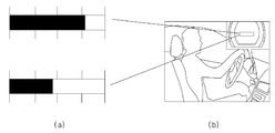
도 11의 (a)에서 보는 바와 같이, 주행 조작 감지부(161A)에 포함된 다수의 조작 감지부는 차량의 주행을 위한 조작을 감지하며, 가속도 패달(ACC pad) 조작, 브레이크 패달(Break pad) 조작, 멀티펑션 스위치(Multi function S/W) 조작, 조향 핸들(Steering wheel) 조작 중 적어도 하나의 항목의 주행 조작을 감지한다. As shown in (a) of FIG. 11, a plurality of operation detection units included in the driving
나아가, 주행 조작 감지부(161A)는 수동 기어 차량의 클러치 패달 조작 또는 변속기 조작 항목을 더 포함하는 주행 조작 정보를 획득할 수 있다. 이때, 주행 조작 감지부(161A)는 차량의 속도를 확인하여, 차량의 속도가 일정 속도(예를 들어, 10km/h) 이상인 경우에 주행 조작 정보를 획득할 수 있다. Furthermore, the driving
일 예로, 주행 조작 감지부(161A)는 소정 시간 동안 일정 시간마다 운전자에 의해 조작되는 가속도 패달의 작동 횟수(![]()
![]()
마찬가지로, 주행 조작 감지부(161A)는 브레이크 패달 및 클러치 패달 또한 일정 시간마다 조작되는 작동 횟수(각각, ![]()
![]()
다른 예로, 주행 조작 감지부(161A)는 소정 시간 동안 운전자에 의해 조작되는 멀티펑션의 각 스위치의 작동 횟수(![]()
![]()
또 다른 예로, 주행 조작 감지부(161A)는 소정 시간 동안 운전자에 의해 조작되는 스티어링 휠의 각속도(![]()
![]()
부주의 상태 감지부(161B)는 차량의 주행 시 부가적으로 동작되는 제어 유닛의 조작 및 운전자의 동작을 감지하기 위한 구성으로서, 오디오 신호입력 감지부(T1), 공조 신호 입력 감지부(T2), 내비게이션 신호 입력 감지부(T3) 등과 같은 다수의 감지부를 포함할 수 있다.The careless
또한, 부주의 상태 감지부(161B)는 운전자의 동작(Visual Factor, Verbal Factor)을 감지하기 위해, 졸음지수 측정부(P), 시선 방향 측정부(E) 및 음성 감지부(V)를 포함할 수 있다. 이와 같은 부주의 상태 감지부(161B)에 포함된 다수의 감지부 및 측정부는 도 2에 예시된 바와 같이, 차량의 소정 위치에 구현되어 주변기기 조작, 운전자의 얼굴 영상, 운전자의 음성 중 적어도 하나의 항목의 정보를 이용하여 부주의 상태 정보를 획득할 수 있다.In addition, the careless
일 예로, 부주의 상태 감지부(161B)는 차량 주행 중 운전자에 의해 주변 기기가 조작되는 횟수(![]()
![]()
다른 예로, 부주의 상태 감지부(161B)는 차량 내 소정 위치에 장착된 마이크를 통해 운전자의 음성을 감지할 수 있다. 예를 들어, 부주의 상태 감지부(161B)는 마이크로부터 일정 시간 동안 수신되는 음성 데이터의 펄스 크기(음성 크기) 및 음성 발생 시간을 확인할 수 있다. 바람직하게, 부주의 상태 감지부(120)는 메모리에 기저장된 펄스 임계값을 이용하여 소정 시간(예를 들어, 200ms) 동안 펄스 임계값 이상의 펄스 크기의 음성 데이터가 수신되는 시간을 감지하여 부주의 상태 정보로 획득할 수 있다.As another example, the careless
또 다른 예로, 부주의 상태 감지부(161B)는 차량 소정 위치에 장착된 카메라를 통해 운전자의 얼굴 영상을 수신하여 운전자의 눈감음 정보 및 주시 태만 정보를 획득할 수 있다. 이때, 카메라는 주간 및 야간에 영상을 기록할 수 있도록 도 11의 (b)와 같이 근적외선 LED (Near Infrared LED)를 포함할 수 있다. As another example, the careless
바람직하게, 부주의 상태 감지부(161B)는 운전자의 얼굴 영상에서 운전자의 눈 영역 영상을 별도로 추출할 수 있다. 이때, 영상 처리를 통해 운전자의 얼굴 영상으로부터 눈 영역 영상이 추출될 수 있다. 즉, 부주의 상태 감지부(161B)는 카메라로부터 획득되는 운전자의 얼굴 영상 및 상기 얼굴 영상에 포함된 눈 영역 영상을 이용하여 운전자가 눈감음 및 주시 태만과 같은 부주의 상태 정보를 획득할 수 있다.Preferably, the
부주의 상태 감지부(161B)는 운전자의 얼굴 영상에서 추출되는 눈 영역 영상을 이용하여 운전자의 눈감음 정보를 획득할 수 있다.The careless
도 12를 참조하면, 부주의 상태 감지부(161B)는 눈 영역 영상에서 눈꺼풀 영역을 감지하여 눈꺼풀의 각도인 ∠A와 ∠B의 합이 기설정된 소정의 임계 각도값인 ∠C 이하(∠A + ∠B ≤ ∠C)인 경우, 운전자가 눈을 감은 것으로 확인한다.Referring to FIG. 12, the careless
부주의 상태 감지부(161B)는 일정 시간 동안마다 눈꺼풀의 각도를 확인하여 운전자가 눈을 감은 횟수를 감지하여, 소정 시간 동안 눈을 감은 횟수와 일정 시간값을 연산하여 운전자의 졸음 시간(졸음 지수)을 획득할 수 있다. 예를 들어, 부주의 상태 감지부(161B)는 1초 내 250ms 구간으로 나누어 눈 감은 횟수를 측정(카운트)하며, 카운트가 3인 경우, 운전자가 눈을 감은 시간(졸음 시간)은 750ms로 획득할 수 있다.The careless
또한, 부주의 상태 감지부(161B)는 운전자의 얼굴 영상 및 상기 얼굴 영상에 포함된 눈 영역 영상을 이용하여 운전자의 주시 태만 정보를 획득할 수 있다. In addition, the careless
도 15를 참조하면, 주시 태만의 범위는 스티어링 휠의 각도가 아닌 차량 바퀴의 각도 즉, 차량 중앙에서 바퀴의 변화 각도량(도 15의 (a)의 ΘA 혹은 ΘB)를 근거로 하여, 차량 주행 시 부하가 없는 가시거리(η)에 운전자의 시야 범위가 있는지의 여부(시선 방향)를 확인하여 주시 태만 정보를 획득한다. 시야 범위는 카메라로부터 획득되는 운전자의 얼굴 영상에서 얼굴의 각도(도 15의 (b)의 α)를 산출한 다음, 눈 영역 영상에서 눈동자의 위치(동공의 방향)(도 15의 (c)의 (β)를 측정하여 확인할 수 있다.Referring to FIG. 15, the range of neglect is based on the angle of the wheel of the vehicle, not the angle of the steering wheel, that is, the change angle of the wheel at the center of the vehicle (ΘA or ΘB in FIG. 15A). Check whether the driver's field of view is in the line of sight (η) with no visual load (viewing direction), and obtain negligence information. The field of view is obtained by calculating the angle of the face (α in FIG. 15 (b)) in the face image of the driver obtained from the camera, and then the position of the pupil (the direction of the pupil) in the eye region image (in FIG. 15 (c)). (β) can be measured and confirmed.
구체적으로, 부주의 상태 감지부(120)는 스티어링 휠 각도가 소정 각도 이내에서 변속기의 레버가 D 단 또는 N 단의 경우, 일정 시간 이상 운전자의 시선이 주행 무부하 가시 범위(a, b)에 미진입시, 주시 태만으로 판단 및 그 시간을 확인하여 주시 태만 정보를 획득할 수 있다. 예를 들어, 부주의 상태 감지부(161B)는 차량의 속도가 10Km 이상에서 변속기 레버 D 또는 N 시 스티어링휠 각도 ±15˚이내일 경우, 1.5초 이상 운전자의 시선이 주행 무부하 가시범위(a, b)에 미진입시 차량 전방에 대한 주시 태만으로 판단할 수 있다.In detail, when the steering wheel angle is within the predetermined angle and the lever of the transmission is in the D or N stage, the driver's gaze is not entered into the driving no-load visual range (a, b) for a predetermined time. In this case, the information on the judgment and the time can be obtained by checking the judgment and the time. For example, when the speed of the vehicle is within 10 km or more of the steering wheel angle ± 15 degrees at the transmission lever D or N, the driver's gaze is 1.5 seconds or more when the driver's gaze is at a no-load viewing range (a, b). ), It can be judged by neglecting the front of the vehicle when not entering.
제어부(163)는 운전자 상태 감지 시스템(160)의 전반적인 동작을 수행하는 구성으로서, 전자 제어 유닛일 수 있다. 예를 들어, 제어부(163)는 DWC(Driving Workload Compute Unit)라고 지칭할 수 있다.The
구체적으로, 제어부(163)는 획득부(161)로부터 획득된 주행 조작 정보 및 부주의 상태 정보를 이용하여 주행 조작 부하량 및 주행 방해 부하량을 계산한다. In detail, the
또한, 주행 조작 부하량과 주행 방해 부하량을 서로 비교하여 운전자의 안전운전 상태를 판단하고, 판단 결과 안전운전 상태가 아닌 것으로 판단되면 경고 정보가 출력되도록 출력부(165)를 제어한다.In addition, the driving operation load amount and the driving disturbance load amount are compared with each other to determine the driver's safe driving state, and when it is determined that it is not the safe driving state, the
먼저, 제어부(163)는 획득부(161)로부터 획득된 주행 조작 정보 및 부주의 상태 정보를 이용하여 주행 조작 부하량 및 주행 방해 부하량을 계산한다.First, the
일 예로, 제어부(163)는 획득부(161)의 주행 조작 감지부(161)로부터 획득되는 주행 조작 정보를 이용하여 주행 조작 부하량(![]()
![]()
구체적으로, 제어부(163)는 주행 조작 감지부(161A)로부터 획득되는 주행 조작 정보와, 주행 조작 정보의 항목별 가중치를 메모리로부터 불러와 주행 조작 부하량을 계산한다.In detail, the
여기서, 가중치는 사전에 다양한 실험을 통해 주행 조작 정보의 항목별로 추출되어 기설정된 값 일 수 있다. 또는, 가중치는 사전에 작업자에 의해 항목별로 임의로 기설정된 값일 수 있다. 또한, 메모리는 데이터를 저장하기 위한 저장 수단으로서, 비휘발성 메모리일 수 있다.Here, the weight may be a predetermined value extracted for each item of the driving operation information through various experiments in advance. Alternatively, the weight may be a value arbitrarily preset by the operator in advance for each item. In addition, the memory may be a nonvolatile memory as storage means for storing data.
바람직하게, 제어부(163)는 주행 조작 정보에 포함된 항목 및 그 항목에 대응되는 가중치를 이용하여 각 항목에 대한 부하량을 계산할 수 있다. 예를 들어, 획득부(161)로부터 가속도 패달 조작, 브레이크 패달 조작, 멀티펑션 스위치 조작 및 조향 핸들 조작의 주행 조작 정보가 획득되는 경우, 제어부(163)는 메모리로부터 가속도 패달 조작에 대한 가중치(![]()
![]()
![]()
![]()
![]()
![]()
만약, 획득부(161)에서 200ms 동안 50ms 단위로 각 항목들의 시간 및 횟수 정보를 획득되는 경우, 제어부(163)에 의해 계산되는 200ms 동안의 주행 조작 부하량(![]()
If the ![]()
![]()
![]()
이러한 주행 조작 정보에 포함된 각 항목들은 경우에 따라 가감될 수 있다. 만약, 차량의 종류에 따라 주행 조작 정보에 클러치 패달 조작 및 변속기 조작이 포함된 경우, 제어부(163)는 클러치 패달 조작에 대한 가중치 및 변속기 조작에 대한 가중치를 더 고려하여 주행 조작 부하량을 계산할 수 있다.Each item included in the driving operation information may be added or subtracted as the case may be. If the clutch operation and the transmission operation are included in the driving operation information according to the type of the vehicle, the
다른 예로, 제어부(163)는 획득부(161)의 부주의 상태 감지부(161B)로부터 획득되는 부주의 상태 정보를 이용하여 주행 방해 부하량(![]()
![]()
제어부(163)는 획득부(161)의 부주의 상태 감지부(161B)로부터 획득되는 주변기기 조작의 횟수를 이용하여 주변 기기 조작 부하량(T(n))을 산출할 수 있다. The
예를 들어, 제어부(161)는 메모리에 기저장된 주변 기기 조작에 대한 가중치를 더 고려하여 주변 기기 조작 부하량을 계산할 수 있다. 만약, 획득부(161)에서 200ms 동안 운전자에 의한 주변기기 조작의 입력 횟수를 획득하는 경우, 제어부(163)는 주변기기 조작 입력 횟수와 가중치를 연산하여 주변 기기 조작 부하량(T(n))을 산출할 수 있다.For example, the
나아가, 제어부(163)는 획득부(161)의 부주의 상태 감지부(161B)로부터 획득되는 운전자의 음성 데이터를 이용하여 음성 부하량(V(n))을 산출할 수 있다. 구체적으로, 제어부(163)는 메모리에 저장된 음성 데이터의 펄스 임계값을 고려하여 음성 부하량을 계산할 수 있다. 예를 들어, 제어부(163)는 획득부(161)의 부주의 상태 감지부(161B)로부터 일정 시간(예를 들어, 200ms) 동안 획득되는 운전자의 음성 데이터에서 펄스 임계값 이상의 음성 데이터가 수신되는 시간을 연산하여 음성 부하량(V(t))을 산출할 수 있다.In addition, the
또한, 제어부(163)는 획득부(161)의 부주의 상태 감지부(161B)에서 획득되는 부주의 상태 정보 중 눈감음 정보 및 주시 태만 정보를 이용하여 졸음 부하량(P(t)) 및 주행 주시 태만 부하량(E(t))을 산출할 수 있다.In addition, the
도 13의 그래프를 참조하면, 운전자가 지각 상태일 때는 상당히 안정적으로 그래프의 변동 폭이 좁으며, 반면에 졸음 상태일 때의 PERCLOS값은 변화가 상당히 심하며 전체적인 수치가 지각 상태보다 높게 나타난다. 여기서 PERCLOS 값은 수학식 11과 같이 나타낼 수 있다.Referring to the graph of FIG. 13, when the driver is in the late state, the fluctuation range of the graph is fairly stable, whereas the PERCLOS value when the drowsiness state is significantly changed and the overall value is higher than the perceptual state. Here, the PERCLOS value may be expressed as in Equation 11.

도 13의 그래프에 근거하여 제어부(163)에 의해, PERCLOS의 값이 소정 퍼센트(30%) 이상으로 확인되는 경우, 즉, 부주의 상태 감지부(161B)를 통해 소정 시간(예를 들어, 250초)를 기준으로 일정 시간(예를 들어, 약 75초) 운전자가 눈을 감은 것으로 확인되는 경우, 제어부(163)는 차량 경보음이 출력되도록 출력부(165)를 제어한다. 이는, 졸음 운전이 차량 주행중 가장 높은 위험 요소이므로 일정 시간 이상 운전자가 눈을 감은 것으로 확인되면 운전자가 졸음 운전 중인 것으로 판단하여 즉각적으로 경보음이 출력되어 운전자에게 경고하기 위함이다.Based on the graph of FIG. 13, when the value of PERCLOS is determined to be greater than or equal to a predetermined percentage (30%) by the
이때, 제어부(163)는 도 14의 흐름도를 참조하여 운전자의 눈감음 확인 동작을 수행할 수 있다. In this case, the
구체적으로, 제어부(163)는 차량 속도(V)가 소정 속도 이상(예를 들어, V≥10Km/h)인지 여부를 판단한다(S1410). 소정 속도 이상을 판단하면, 제어부(163)는 부주의 상태 감지부(120)를 통해 소정의 측정 시간(N) 동안 일정 시간(x)(예를 들어, 250ms 또는 0.25s로 나타냄) 마다 눈꺼풀의 각도를 통해 눈감은 횟수(y)를 확인하여 운전자의 눈감은 시간(졸음 시간)을 산출할 수 있다. In detail, the
제어부(163)는 눈꺼풀의 각도가 ∠A+∠B≤∠C인지 여부를 판단한다(S1420). 눈꺼풀의 각도가 ∠A+∠B≤∠C이면, 눈을 감은 것으로 판단하여 눈감은 횟수를 카운트(y++)한다(S1430). The
제어부(163)는 일정 시간(x)마다 눈감은 횟수(y)를 카운트하여(x+=0.25, y++), 1초 동안 눈 감은 횟수가 3회(x=1, y=3)이면(S1440), 환산 인자(P)값을 카운트(P++)하고, 1초씩를 늘리면서(N++) 위의 과정을 반복한다(S1450). The
만약, 250초의 측정 시간 이내에서 환산 인자(P)가 100 이상이 되면(S1460), 제어부(163)는 경고(WARNING) 이벤트를 발생하도록 출력부(165)를 제어한다(S1470). 이때, 제어부(163)는 환산 인자(P)값을 99로 변경하고, 측정시간(N)을 1초 감소시킨 후(P=99, N-=1), 위의 과정들을 반복 수행하고, 운전자의 눈감은 시간(졸음 시간)을 산출할 수 있다. 나아가, 제어부(163)는 일정 시간 동안 PERCLOS 값이 30% 이상인 경우를 확인하여 졸음 부하량(P(t))을 산출할 수 있다.If the conversion factor P is greater than or equal to 100 within a measurement time of 250 seconds (S1460), the
또한, 제어부(163)는 부주의 상태 감지부(161B)에서 획득되는 주시 태만 정보를 이용하여 주시 태만 부하량(E(t))을 산출한다. In addition, the
도 15의 (a)에 도시된 바와 같이, 시야 범위가 주행 무부하 가시거리(η)를 벗어나면, 벗어난 범위에 따라 부하 인자(V)의 인자값이 달라질 수 있다. As shown in FIG. 15A, when the viewing range is out of the running no-load viewing distance η, the factor value of the load factor V may vary according to the deviation range.
벗어난 범위(a', b')는 기설정되며, 현재 운전자의 시야 범위가 해당하는 범위별로 부하 인자의 인자값을 메모리로부터 불러내어 주시 태만 부하량(E(t))을 산출할 수 있다.The deviation ranges a 'and b' are preset, and the load amount E (t) can be calculated by recalling the factor value of the load factor from the memory for each range corresponding to the current driver's field of view.
제어부(163)는 산출된 주변 기기 조작 부하량(T(n)), 음성 부하량(V(t)), 졸음 부하량(P(t)) 및 주시 태만 부하량(E(t))을 연산하여 주행 방해 부하량(![]()
![]()
또한, 차량의 상태 및 경우에 따라서는 부주의 상태 정보를 이용하여 획득된 부하량들 중 주행 방해 부하량의 계산에 고려되지 않는 부하량이 있을 수도 있다.In addition, there may be a load that is not considered in the calculation of the disturbance load of the loads obtained using the state of the vehicle and in some cases careless state information.
제어부(163)는 주행 부하량(![]()
![]()
![]()
![]()
구체적으로, 제어부(163)는 주행 부하량(![]()
![]()
![]()
![]()
![]()
Specifically, the ![]()
![]()
![]()
![]()
![]()

여기서, t는 시간 값이며, n은 횟수값이다.
Where t is a time value and n is a count value.
출력부(165)는 화면 출력 및 경보음 출력을 위한 구성으로서, 액정 표시 장치(LCD) 및 스피커를 포함한다. 바람직하게, 출력부(165)는 도 16의 (b)와 같이 클러스터를 통해 화면과 경보음을 출력할 수 있다. 또는, 출력부(165)는 오디오 디스플레이를 통해 화면 출력할 수도 있다. 나아가, 출력부(165)는 제어부(163)의 안전운전 상태 판단 결과 및 그 결과값을 도 16의 (a)와 같이 막대 그래프 형식으로 화면에 표시할 수 있다. 이때, 막대 그래프는 다양한 색상으로 표시될 수 있다.The
예컨대, 제어부(163)는 주행 부하량과 주행 방해 부하량의 차이에 따른 현재 부하량의 정보를 막대 그래프로 화면 표시하도록 출력부(300)를 제어할 수 있다.For example, the
구체적으로, 제어부(163)에 의해 계산된 주행 부하량(![]()
![]()
![]()
![]()
![]()
![]()
만약, 차량 주행이 어려워지는 순간을 75%로 기설정된 경우, 제어부(163)는 결과값(C)이 75% 이상인 경우 막대 그래프의 색상을 적색으로 표시하도록 출력부(165)를 제어할 수 있고, 막대 그래프가 점멸되도록 출력부(165)를 제어하여 운전자에게 차량 주행의 위험을 상기시킬 수 있다. If the moment when the vehicle becomes difficult to be preset to 75%, the
또한, 이러한 경우 제어부(163)는 경보음이 출력되도록 출력부(165)를 제어하여 운전자에게 경고할 수 있다. In this case, the
결과값(C)이 75% 미만인 경우에는 막대 그래프가 녹색으로 표시되어 운전자에게 안전한 상태임을 알릴 수 있다.If the result value (C) is less than 75%, the bar graph is displayed in green to inform the driver that it is safe.
나아가, 제어부(163)는 주행 부하량(![]()
![]()
![]()
![]()
![]()
![]()
덧붙여, 제어부(163)는 출력부(165)를 통해 출력되는 경보음의 음량을 결과값(C)에 거듭 제곱 비례하도록 높여 운전자에게 주행 위험을 강하게 경고할 수 있다.In addition, the
이와 같이 본 발명에 따르면, 차량 주행에 따라 발생하는 주행 부하량과 주변기기 및 운전자의 졸음 등과 같이 주행에 방해되는 주행 방해 부하량을 비교하여 운전자의 안전운전 상태를 확인하며, 차량 운전에 방해되는 부하량이 높은 경우 운전자에게 경고하며, 경우에 따라서는 차량 주행에 필수적이지 않은 요소(예를 들어, 주변기기)의 동작을 강제적으로 정지시켜 차량 운전에 방해가 되는 주행 방해 부하량을 감소시켜 운전자가 안전운전을 할 수 있도록 하는 효과를 창출한다.As described above, according to the present invention, the driving load amount generated according to the driving of the vehicle is compared with the disturbance load disturbing the driving such as peripherals and drowsiness of the driver to check the driver's safe driving state, and the load amount hindering driving the vehicle is high. In this case, the driver is warned, and in some cases, the driver is forced to stop the operation of elements that are not essential to driving the vehicle (e.g., peripherals), thereby reducing the amount of disturbing load that interferes with driving the vehicle. Create effects that make
도 17은 본 발명의 실시예에 따른 운전자 상태 감지 방법 흐름도이다.17 is a flowchart illustrating a driver state detection method according to an embodiment of the present invention.
먼저, 운전자 상태 감지 시스템(160)는 주행 조작 정보 및 운전자의 부주의 상태 정보를 획득한다(S1710).First, the driver
구체적으로, 운전자 상태 감지 시스템(160)은 차량 주행에 필수적인 주행 제어 유닛들의 주행 조작을 감지하여 주행 조작 정보를 획득한다. In detail, the driver
예를 들어, 운전자 상태 감지 시스템(160)은 가속도 패달(ACC pad) 조작, 브레이크 패달(Break pad) 조작, 멀티펑션 스위치(Multi function S/W) 조작, 조향 핸들(Steering wheel) 조작 중 적어도 하나의 항목의 주행 조작을 감지하여 주행 조작 정보를 획득한다. 이때, 운전자 상태 감지 시스템(160)은 차량의 속도를 확인하여 차량의 속도가 일정 속도(예를 들어, 10km/h) 이상인 경우에 주행 조작 정보를 획득할 수 있다.For example, the driver
일 예로, 운전자 상태 감지 시스템(160)은 소정 시간 동안 일정 시간마다 운전자에 의해 조작되는 가속도 패달의 작동 횟수(![]()
![]()
![]()
![]()
다른 예로, 운전자 상태 감지 시스템(160)은 소정 시간 동안 운전자에 의해 조작되는 멀티펑션의 각 스위치의 작동 횟수(![]()
![]()
또 다른 예로, 운전자 상태 감지 시스템(160)은 소정 시간 동안 운전자에 의해 조작되는 스티어링 휠의 각속도(![]()
![]()
나아가, 운전자 상태 감지 시스템(160)은 차량 주행 중 선택적으로 운전자에 의해 제어되는 주변 기기, 운전자의 음성 및 얼굴 정보를 통해 부주의 상태 정보를 획득한다.In addition, the driver
일 예로, 운전자 상태 감지 시스템(160)은 차량 주행 중 운전자에 의해 주변 기기가 조작되는 횟수(![]()
![]()
다른 예로, 운전자 상태 감지 시스템(160)은 차량 내 소정 위치에 장착된 마이크를 통해 운전자의 음성을 감지할 수 있다. 예를 들어, 운전자 상태 감지 시스템(160)은 마이크로부터 일정 시간 동안 수신되는 음성 데이터의 펄스 크기(음성 크기) 및 음성 발생 시간을 확인할 수 있다.As another example, the driver
또 다른 예로, 운전자 상태 감지 시스템(160)은 차량 소정 위치에 장착된 카메라를 통해 운전자의 얼굴 영상을 수신하여 운전자의 눈감음 정보 및 주시 태만 정보를 획득할 수 있다. 이때, 카메라는 주간 및 야간에 영상을 기록할 수 있도록 도 11의 (b)와 같이 근적외선 LED (Near Infrared LED)를 포함할 수 있다. As another example, the driver
바람직하게, 운전자 상태 감지 시스템(160)는 운전자의 얼굴 영상에서 운전자의 눈 영역 영상을 별도로 추출할 수 있다. 이때, 운전자의 얼굴 영상은 영상 처리되어 눈 영역 영상이 추출될 수 있다. 즉, 운전자 상태 감지 시스템(160)은 카메라로부터 수신되는 운전자의 얼굴 영상 및 눈 영역 영상을 이용하여 운전자가 눈감음 정보 및 주시 태만 정보와 같은 부주의 상태 정보를 획득할 수 있다.Preferably, the driver
운전자 상태 감지 시스템(160)은 운전자의 얼굴 영상에서 추출되는 눈 영역 영상을 이용하여 운전자의 눈감음 정보를 획득할 수 있다. 도 3을 참조하면, 운전자 상태 감지 시스템(160)은 눈 영역 영상에서 눈꺼풀 영역을 감지하여 눈꺼풀의 각도인 ∠A와 ∠B의 합이 기설정된 소정의 임계 각도값인 ∠C 이하(∠A + ∠B ≤ ∠C)인 경우, 운전자가 눈을 감은 것으로 확인한다. The driver
운전자 상태 감지 시스템(160)은 일정 시간 동안마다 눈꺼풀의 각도를 확인하여 운전자가 눈을 감은 횟수를 감지하여, 소정 시간 동안 눈을 감은 횟수와 일정 시간값을 연산하여 운전자의 눈감음 정보(졸음 시간)를 획득할 수 있다.The driver
또한, 운전자 상태 감지 시스템(160)는 운전자의 얼굴 영상 및 눈 영역 영상을 이용하여 운전자의 주시 태만 정보를 획득할 수 있다. In addition, the driver
도 15를 참조하면, 주시 태만의 범위는 스티어링 휠의 각도가 아닌 차량 바퀴의 각도 즉, 차량 중앙에서 바퀴의 변화 각도량(도 15의 (a)의 ΘA 혹은 ΘB 와 같은 예시)를 근거로 하여, 차량 주행 시 부하가 없는 가시거리(η)에 운전자의 시야 범위가 있는지의 여부를 확인하여 주시 태만 정보를 획득한다. 여기서, 시야 범위는 카메라로부터 획득되는 운전자의 얼굴 영상에서 얼굴의 각도(도 15의 (b)의 α)를 산출한 다음, 눈 영역 영상에서 눈동자의 위치(동공의 방향)(도 15의 (c)의 (β)를 측정하여 확인할 수 있다. Referring to FIG. 15, the range of neglect of attention is based on the angle of the wheel of the vehicle, not the angle of the steering wheel, that is, the amount of change of the wheel angle at the center of the vehicle (such as ΘA or ΘB in FIG. 15A). When the vehicle travels, the driver checks whether the driver's field of view ranges at the unsighted visual distance η to obtain information on negligence. Here, the field of view is calculated by the angle of the face (α in Fig. 15 (b)) in the driver's face image obtained from the camera, and then the position of the pupil (the direction of the pupil) in the eye region image (Fig. 15 (c) Can be confirmed by measuring (β).
구체적으로, 스티어링 휠 각도가 소정 각도 이내에서 변속기의 레버가 D단 또는 N단의 경우, 일정 시간 이상 운전자의 시선이 주행 무부하 가시 범위(a, b)에 미진입시, 운전자 상태 감지 시스템(160)은 주시 태만으로 판단 및 그 시간을 확인하여 주시 태만 정보를 획득할 수 있다.In detail, when the steering wheel angle is within the predetermined angle and the lever of the transmission is in the D or N stage, when the driver's gaze does not enter the driving no-load visibility range (a, b) for more than a predetermined time, the driver
운전자 상태 감지 시스템(160)은 단계 S1710에서 획득된 주행 조작 정보 및 부주의 상태 정보를 이용하여 주행 조작 부하량 및 주행 방해 부하량을 계산한다(S1720).The driver
일 예로, 운전자 상태 감지 시스템(160)는 주행 조작 정보를 이용하여 주행 조작 부하량(![]()
![]()
여기서, 가중치는 사전에 다양한 실험을 통해 주행 조작 정보의 항목별로 추출되어 기설정된 값 일 수 있다. 또는, 가중치는 사전에 작업자에 의해 항목별로 임의로 기설정된 값일 수 있다.Here, the weight may be a predetermined value extracted for each item of the driving operation information through various experiments in advance. Alternatively, the weight may be a value arbitrarily preset by the operator in advance for each item.
바람직하게, 운전자 상태 감지 시스템(160)은 주행 조작 정보에 포함된 항목 및 그 항목에 대응되는 가중치를 이용하여 각 항목에 대한 부하량을 계산할 수 있다. 예를 들어,운전자 상태 감지 시스템(160)은 가속도 패달 조작, 브레이크 패달 조작, 멀티펑션 스위치 조작 및 조향 핸들 조작의 주행 조작 정보가 획득되는 경우, 운전자 상태 감지 시스템(160)은 기저장되어 있는 가속도 패달 조작에 대한 가중치(![]()
![]()
![]()
![]()
![]()
![]()
![]()
![]()
다른 예로, 운전자 상태 감지 시스템(160)은 부주의 상태 정보를 이용하여 주행 방해 부하량(![]()
![]()
운전자 상태 감지 시스템(160)은 주변기기 조작의 횟수를 이용하여 주변 기기 조작 부하량(T(n))을 산출할 수 있다. 예를 들어, 운전자 상태 감지 시스템(160)은 기저장된 주변 기기 조작에 대한 가중치를 더 고려하여 주변 기기 조작 부하량을 계산할 수 있다. 만약, 소정 시간 동안 운전자에 의한 주변기기 조작의 입력 횟수를 획득하는 경우, 운전자 상태 감지 시스템(160)는 주변기기 조작 입력 횟수와 가중치를 연산하여 주변 기기 조작 부하량(T(n))을 산출할 수 있다.The driver
나아가, 운전자 상태 감지 시스템(160)은 운전자의 음성 데이터를 이용하여 음성 부하량(V(n))을 산출할 수 있다. 구체적으로, 운전자 상태 감지 시스템(160)은 기저장된 음성 데이터의 펄스 임계값을 고려하여 음성 부하량을 계산할 수 있다. 예를 들어, 운전자 상태 감지 시스템(10)은 소정 시간 동안 획득되는 운전자의 음성 데이터에서 펄스 임계값 이상의 음성 데이터가 수신되는 시간을 연산하여 음성 부하량(V(t))을 산출할 수 있다.In addition, the driver
또한, 운전자 상태 감지 시스템(160)은 부주의 상태 정보 중 눈감음 정보 및 주시 태만 정보를 이용하여 졸음 부하량(P(t)) 및 주행 주시 태만 부하량(E(t))을 산출할 수 있다.In addition, the driver
이때, 운전자 상태 감지 시스템(10)은 도 14의 흐름도를 참조하여 운전자의 눈감음 확인 동작을 수행할 수 있으며, 차량 속도(V)가 소정 속도 이상에서 소정 시간(N) 동안 일정 시간(x) 마다 눈꺼풀의 각도를 통해 눈감은 횟수(y)를 확인하여 운전자가 눈감은 시간(졸음 시간)을 산출할 수 있다. 나아가, 일정 시간 동안 PERCLOS 값이 30% 이상인 경우를 카운트(P)한 값을 부하 인자로 환산시켜 졸음 부하량(P(t))을 산출할 수 있다.At this time, the driver
또한, 운전자 상태 감지 시스템(160)은 부주의 상태 정보 중 주시 태만 정보를 이용하여 주시 태만 부하량(E(t))을 산출한다. 도 15에서와 같이, 시야 범위가 주행 무부하 가시거리(η)에서 벗어난다면, 벗어난 범위에 따라 부하 인자(V)의 인자값이 달라질 수 있다. 도 15의 (a)에서 벗어난 범위(a' 및 b')는 기설정되며, 현재 운전자의 시야 범위가 해당하는 범위별로 부하 인자의 인자값을 메모리로부터 불러내어 주시 태만 부하량(E(t))을 산출할 수 있다.In addition, the driver
운전자 상태 감지 시스템(160)은 이렇게 산출된 주변 기기 조작 부하량(T(n)), 음성 부하량(V(t)), 졸음 부하량(P(t)) 및 주시 태만 부하량(E(t))을 연산하여 주행 방해 부하량(![]()
![]()
운전자 상태 감지 시스템(160)은 주행 조작 부하량(![]()
![]()
![]()
![]()
![]()
![]()
구체적으로, 운전자 상태 감지 시스템(160)은 주행 부하량(![]()
![]()
![]()
![]()
![]()
![]()
![]()
![]()
![]()
![]()
![]()
![]()
![]()
![]()
![]()
![]()
만약, 차량 주행이 어려워지는 순간을 임계 퍼센트값으로 기설정되어 있고, 단게 S1730의 비교 결과값(C)이 임계 퍼센트값 이상이면, 운전자 상태 감지 장치(10)는 운전자에게 경고한다(S1740). If the moment when it is difficult to drive the vehicle is preset as a threshold percentage value, and if the comparison result value C of step S1730 is equal to or greater than the threshold percentage value, the driver
차량 주행이 어려워지는 순간이 75%로 기설정되고, 단계 S1730의 비교 결과값(C)이 75% 이상이면, 운전자 상태 감지 시스템(160)은 운전자에게 경고한다 예를 들어, 운전자 상태 감지 시스템(160)은 현재 부하량을 나타내는 막대 그래프의 색상을 적색으로 화면 표시하며, 나아가 막대 그래프를 점멸하여 운전자에게 차량 주행의 위험을 상기시킬 수 있다. 또한, 이러한 경우 운전자 상태 감지 시스템(160)은 경보음을 출력하여 운전자에게 경고할 수 있다.If the moment when it becomes difficult to drive the vehicle is set to 75%, and the comparison result C of step S1730 is 75% or more, the driver
만약, 단계 S1730의 비교 결과값(C)이 75% 미만인 경우, 운전자 상태 감지 시스템(160)은 현재 부하량을 나타내는 막대 그래프를 녹색으로 표시하여 운전자에게 안전한 상태임을 알릴 수 있다(S1750).If the comparison result value C of step S1730 is less than 75%, the driver
이와 같이 본 발명에 따르면, 차량 주행에 따라 발생하는 주행 부하량과 주변기기 및 운전자의 졸음 등과 같이 주행에 방해되는 주행 방해 부하량을 비교하여 운전자의 안전운전 상태를 확인하며, 차량 운전에 방해되는 부하량이 높은 경우 운전자에게 경고하며, 경우에 따라서는 차량 주행에 필수적이지 않은 요소(예를 들어, 주변기기)의 동작을 강제적으로 정지시켜 차량 운전에 방해가 되는 주행 방해 부하량을 감소시켜 운전자가 안전운전을 할 수 있도록 하는 효과를 창출한다.As described above, according to the present invention, the driving load amount generated according to the driving of the vehicle is compared with the disturbance load disturbing the driving such as peripherals and drowsiness of the driver to check the driver's safe driving state, and the load amount hindering driving the vehicle is high. In this case, the driver is warned, and in some cases, the driver is forced to stop the operation of elements that are not essential to driving the vehicle (e.g., peripherals), thereby reducing the amount of disturbing load that interferes with driving the vehicle. Create effects that make
이와 같이 본 발명에 따르면, 차량 주행에 따라 발생하는 주행 부하량과 주변기기 및 운전자의 졸음 등과 같이 주행에 방해되는 주행 방해 부하량을 비교하여 운전자의 안전운전 상태를 확인하며, 차량 운전에 방해되는 부하량이 높은 경우 운전자에게 경고하며, 경우에 따라서는 차량 주행에 필수적이지 않은 요소(예를 들어, 주변기기)의 동작을 강제적으로 정지시켜 차량 운전에 방해가 되는 주행 방해 부하량을 감소시켜 운전자가 안전운전을 할 수 있도록 하는 효과를 창출한다.As described above, according to the present invention, the driving load amount generated according to the driving of the vehicle is compared with the disturbance load disturbing the driving such as peripherals and drowsiness of the driver to check the driver's safe driving state, and the load amount hindering driving the vehicle is high. In this case, the driver is warned, and in some cases, the driver is forced to stop the operation of elements that are not essential to driving the vehicle (e.g., peripherals), thereby reducing the amount of disturbing load that interferes with driving the vehicle. Create effects that make
이상 설명한 바와 같이, 본 발명은 운전 성향이 서로 다른 복수의 운전자에 의해 차량이 주행되는 경우, 각 운전자별로 상이한 운전 패턴 학습 및 운전 상황의 고려 없이 학습함으로써 발생하였던 운전자 성향 인식 불량을 제거한다. As described above, when the vehicle is driven by a plurality of drivers having different driving tendencies, the present invention eliminates a driver tendency recognition defect caused by learning without considering different driving patterns and driving conditions for each driver.
또한 본 발명은 역광 및 터널 진출입 시, 횡방향 제어시 차선 미인식에 대한 문제점을 제거하여 횡방향 제어기 가용 범위를 확대한다. In addition, the present invention eliminates the problem of lane unrecognition in the horizontal direction control in the backlight and tunnel entry and exit, thereby expanding the horizontal controller available range.
또한 본 발명은 추후 개발될 통합 무인 차량 제어기에도 적용할 수 있다.The present invention can also be applied to an integrated driverless vehicle controller to be developed later.
본 발명은 상기한 바와 같이 설명된 실시 예들의 구성과 방법이 한정되게 적용될 수 있는 것이 아니라, 실시 예들은 다양한 변형이 이루어질 수 있도록 각 실시 예들의 전부 또는 일부가 선택적으로 조합되어 구성될 수도 있다.The present invention is not limited to the configuration and method of the embodiments described as described above, the embodiments may be configured by selectively combining all or some of the embodiments so that various modifications can be made.
Claims (10)
상기 자차의 주변 상황을 감지하는 외부 센서로부터 입력받은 주변 환경 정보를 이용하여 주위 차량 궤적을 생성하는 주위 차량 궤적 생성부;
상기 주위 차량 궤적과 상기 자차 주행 궤적 간의 차이인 궤적 거리와 기 설정된 임계값 간의 비교 결과를 나타내는 궤적 부하량을 계산하는 궤적 부하량 계산부; 및
상기 계산된 궤적 부하량에 상응하는 운전자 위험 지수를 생성하는 위험지수 관리부를 포함하고,
운전자가 일정 시간동안 차량 주행과 관련된 조작 장치를 조작하는 횟수를 검출하여 주행 조작 부하량을 계산하고, 운전자의 시야 범위와 바퀴의 각도에 근거하여 주시 태만 정보를 획득한 후 주행 방해 부하량을 계산하되, 상기 주행 조작 부하량과 상기 주행 방해 부하량을 비교한 결과에 따라 경고 정보를 출력하는 출력부를 더 포함하는 차량용 운전자 위험 지수 관리 시스템.
A vehicle driving trajectory generation unit configured to generate a vehicle driving trajectory using the vehicle driving information received from an internal sensor detecting a driving state of the vehicle;
A surrounding vehicle trajectory generation unit configured to generate a surrounding vehicle trajectory by using surrounding environment information received from an external sensor detecting the surrounding situation of the host vehicle;
A trajectory load calculation unit configured to calculate a trajectory load indicating a comparison result between a trajectory distance which is a difference between the surrounding vehicle trajectory and the own vehicle driving trajectory and a preset threshold value; And
A risk index management unit for generating a driver risk index corresponding to the calculated trajectory load,
After calculating the number of times the driver operates the operation device related to driving the vehicle for a certain time, calculates the driving operation load, and based on the driver's field of view and the angle of the wheel, obtains negligence information, and then calculates the driving disturbance load. And an output unit configured to output warning information according to a result of comparing the driving operation load amount with the driving disturbance load amount.
The vehicle driver risk index management system of claim 1, further comprising an ambient vehicle load calculation unit configured to calculate an ambient vehicle load in consideration of the number of vehicles in the front / rear / sides and lane change included in the surrounding environment information.
충돌 소요 시간(Time To Collision: TTC)을 기반으로 상기 자차를 중심으로 다수의 위험 영역을 구획하고, 구획된 각 위험 영역별 차량 개수와 차선 변경 유무를 고려한 주위 차량 부하량을 계산하는 것인 차량용 운전자 위험 지수 관리 시스템.
The method of claim 2, wherein the surrounding vehicle load calculation unit,
A vehicle driver that divides a plurality of dangerous areas based on the own vehicle based on a time to collision (TTC), and calculates the amount of surrounding vehicle considering the number of vehicles and lane change for each divided danger area. Risk Index Management System.
상기 궤적 부하량과 상기 주위 차량 부하량을 합산한 값에 상응하는 상기 운전자 위험 지수를 생성하는 것인 차량용 운전자 위험 지수 관리 시스템.
The method of claim 2, wherein the risk index management unit,
And generate the driver risk index corresponding to the sum of the trajectory load and the surrounding vehicle load.
The vehicle driver risk index management system of claim 1, further comprising a road load calculator configured to calculate a road load in consideration of a road shape, a road surface state, and a traffic state included in the surrounding environment information.
상기 궤적 부하량과 상기 도로 부하량을 합산한 값에 상응하는 상기 운전자 위험 지수를 생성하는 것인 차량용 운전자 위험 지수 관리 시스템.
The method of claim 5, wherein the risk index management unit,
And generate the driver risk index corresponding to the sum of the trajectory load and the road load.
상기 주변 환경 정보에 포함된 도로 형태, 도로 노면 상태 및 교통량 상태를 고려한 도로 부하량을 계산하는 도로 부하량 계산부
를 더 포함하고,
상기 위험지수 관리부는,
상기 궤적 부하량과, 상기 주위 차량 부하량 및 상기 도로 부하량을 합산한 값에 상응하는 상기 운전자 위험 지수를 생성하는 것인 차량용 운전자 위험 지수 관리 시스템.
The apparatus of claim 1, further comprising: an ambient vehicle load calculator configured to calculate an ambient vehicle load in consideration of the number of vehicles in the front / rear / sides and lane change included in the surrounding environment information; And
A road load calculation unit that calculates a road load considering the road type, road surface state, and traffic state included in the surrounding environment information.
More,
The risk index management unit,
And generate the driver risk index corresponding to the sum of the trajectory load, the surrounding vehicle load, and the road load.
상기 자차의 주변 상황을 감지하는 외부 센서로부터 입력받은 주변 환경 정보를 이용하여 상기 자차의 주위 차량 궤적을 생성하는 과정;
상기 주위 차량 궤적과 상기 자차 주행 궤적 간의 차이인 궤적 거리와 기 설정된 임계값 간의 비교 결과를 나타내는 궤적 부하량을 계산하는 과정; 및
상기 계산된 궤적 부하량에 상응하는 운전자 위험 지수를 생성하는 과정을 포함하고,
운전자가 일정 시간동안 차량 주행과 관련된 조작 장치를 조작하는 횟수를 검출하여 주행 조작 부하량을 계산하고, 운전자의 시야 범위와 바퀴의 각도에 근거하여 주시 태만 정보를 획득한 후 주행 방해 부하량을 계산하되, 상기 주행 조작 부하량과 상기 주행 방해 부하량을 비교한 결과에 따라 경고 정보를 출력하는 과정을 더 포함하는 차량용 운전자 위험 지수 관리 방법.
Generating a own vehicle driving trajectory using the own vehicle driving information received from an internal sensor detecting a driving state of the own vehicle;
Generating a surrounding vehicle trajectory of the own vehicle by using the surrounding environment information received from an external sensor detecting the surrounding situation of the own vehicle;
Calculating a trajectory load indicating a comparison result between a trajectory distance which is a difference between the surrounding vehicle trajectory and the own vehicle driving trajectory and a preset threshold value; And
Generating a driver risk index corresponding to the calculated trajectory load,
After calculating the number of times the driver operates the operation device related to driving the vehicle for a certain time, calculates the driving operation load, and based on the driver's field of view and the angle of the wheel, obtains negligence information, and then calculates the driving disturbance load. And outputting warning information according to a result of comparing the driving operation load amount with the driving disturbance load amount.
The method of claim 8, further comprising calculating a surrounding vehicle load in consideration of the number of front, rear, and side vehicles included in the surrounding environment information, and whether there is a lane change.
Priority Applications (4)
| Application Number | Priority Date | Filing Date | Title |
|---|---|---|---|
| KR1020140072280A KR102051142B1 (en) | 2014-06-13 | 2014-06-13 | System for managing dangerous driving index for vehicle and method therof |
| US14/735,528 US9623874B2 (en) | 2014-06-13 | 2015-06-10 | System and method for managing dangerous driving index for vehicle |
| DE102015210630.6A DE102015210630B4 (en) | 2014-06-13 | 2015-06-10 | System and method for handling a driving hazard index for a vehicle |
| CN201510321139.0A CN105197011B (en) | 2014-06-13 | 2015-06-12 | Vehicle steering person's hazard index management system and its method |
Applications Claiming Priority (1)
| Application Number | Priority Date | Filing Date | Title |
|---|---|---|---|
| KR1020140072280A KR102051142B1 (en) | 2014-06-13 | 2014-06-13 | System for managing dangerous driving index for vehicle and method therof |
Publications (2)
| Publication Number | Publication Date |
|---|---|
| KR20150143139A KR20150143139A (en) | 2015-12-23 |
| KR102051142B1 true KR102051142B1 (en) | 2019-12-02 |
Family
ID=54707030
Family Applications (1)
| Application Number | Title | Priority Date | Filing Date |
|---|---|---|---|
| KR1020140072280A Active KR102051142B1 (en) | 2014-06-13 | 2014-06-13 | System for managing dangerous driving index for vehicle and method therof |
Country Status (4)
| Country | Link |
|---|---|
| US (1) | US9623874B2 (en) |
| KR (1) | KR102051142B1 (en) |
| CN (1) | CN105197011B (en) |
| DE (1) | DE102015210630B4 (en) |
Cited By (1)
| Publication number | Priority date | Publication date | Assignee | Title |
|---|---|---|---|---|
| KR20240103928A (en) | 2022-12-27 | 2024-07-04 | 주식회사 티엔티 | System for sensing vehicle driving using responsive holographic animations and method the same |
Families Citing this family (63)
| Publication number | Priority date | Publication date | Assignee | Title |
|---|---|---|---|---|
| DE102014014662A1 (en) * | 2014-09-19 | 2016-03-24 | Mekra Lang North America, Llc | Display device for vehicles, in particular commercial vehicles |
| CN104952249A (en) * | 2015-06-10 | 2015-09-30 | 浙江吉利汽车研究院有限公司 | Driving behavior correcting method and driving behavior correcting device based on internet of vehicles |
| JP5910903B1 (en) * | 2015-07-31 | 2016-04-27 | パナソニックIpマネジメント株式会社 | Driving support device, driving support system, driving support method, driving support program, and autonomous driving vehicle |
| EP3357780B1 (en) | 2015-09-30 | 2022-10-26 | Sony Group Corporation | Driving control device, driving control method, and program |
| EP3357778B1 (en) * | 2015-09-30 | 2022-10-26 | Sony Group Corporation | Driving control device, driving control method, and program |
| JP6316265B2 (en) * | 2015-12-01 | 2018-04-25 | 本田技研工業株式会社 | Lane change control device |
| JP6468204B2 (en) * | 2016-01-15 | 2019-02-13 | スズキ株式会社 | Preventive safety device when changing course of small vehicle |
| CN106094823A (en) * | 2016-06-29 | 2016-11-09 | 北京奇虎科技有限公司 | The processing method of vehicle hazard driving behavior and system |
| KR102536865B1 (en) | 2016-07-22 | 2023-05-25 | 엘지전자 주식회사 | Electronic device and method for controlling the same |
| DE102016215421A1 (en) * | 2016-08-17 | 2018-02-22 | Robert Bosch Gmbh | Method and device for operating an automated motor vehicle |
| CN109843683B (en) * | 2016-10-18 | 2022-03-22 | 本田技研工业株式会社 | vehicle control device |
| CN106494409A (en) * | 2016-11-04 | 2017-03-15 | 大连文森特软件科技有限公司 | Driving Assistance System for Vehicle Control Based on AR Augmented Reality and Big Data |
| CN106503676A (en) * | 2016-11-04 | 2017-03-15 | 大连文森特软件科技有限公司 | Driving assistance system based on AR augmented reality and driving detail collection |
| CN106335512B (en) * | 2016-11-04 | 2019-05-24 | 快创科技(大连)有限公司 | Driving assistance system based on AR augmented reality and vehicle violation record query |
| CN106476810A (en) * | 2016-11-04 | 2017-03-08 | 大连文森特软件科技有限公司 | Driving assistance system based on AR augmented reality and big data |
| KR101846734B1 (en) * | 2016-11-09 | 2018-05-18 | 현대자동차주식회사 | Apparatus and method for determining driving state |
| KR102663017B1 (en) | 2016-11-24 | 2024-05-07 | 현대자동차주식회사 | Vehicle and method for controlling thereof |
| KR20180070401A (en) | 2016-12-16 | 2018-06-26 | 현대자동차주식회사 | System and Method for determining override of self-driving vehicle |
| KR20180104235A (en) * | 2017-03-10 | 2018-09-20 | 만도헬라일렉트로닉스(주) | Method and apparatus for monitoring driver status |
| US11164459B2 (en) | 2017-03-14 | 2021-11-02 | Hyundai Mobis Co., Ltd. | Apparatus and method of safety support for vehicle |
| US10446031B2 (en) * | 2017-03-14 | 2019-10-15 | Hyundai Mobis Co., Ltd. | Apparatus and method of safety support for vehicle |
| US10392012B2 (en) * | 2017-04-24 | 2019-08-27 | Adam Benjamin Tannenbaum | System and method of use for vehicular driving safety |
| DE102017212373A1 (en) * | 2017-07-19 | 2019-01-24 | Volkswagen Aktiengesellschaft | Method for determining a trajectory for an autonomously driving motor vehicle, control device and motor vehicle |
| CN109278747B (en) * | 2017-07-21 | 2021-05-07 | 鸿富锦精密电子(天津)有限公司 | Vehicle monitoring system and method |
| KR102371616B1 (en) * | 2017-11-07 | 2022-03-07 | 현대자동차주식회사 | Apparatus and method for associating sensor data of vehicle |
| KR102302917B1 (en) * | 2017-12-18 | 2021-09-15 | 현대모비스 주식회사 | Apparatus and method for supporting safe driving |
| KR102463722B1 (en) * | 2018-02-20 | 2022-11-07 | 현대자동차주식회사 | Apparatus and method for setting velocity of vehicle |
| KR102016025B1 (en) * | 2018-03-07 | 2019-08-29 | 주식회사 만도 | Apparatus and method for controlling collision alert |
| JP7020215B2 (en) * | 2018-03-19 | 2022-02-16 | 日本電気株式会社 | Extra findings determination device, extra findings determination system, extra findings determination method, program |
| JP6844568B2 (en) * | 2018-03-27 | 2021-03-17 | 日本電気株式会社 | Extra findings determination device, extra findings determination system, extra findings determination method, program |
| US11994860B2 (en) | 2018-06-15 | 2024-05-28 | Allstate Insurance Company | Processing system for evaluating autonomous vehicle control systems through continuous learning |
| JP2021530069A (en) * | 2018-06-26 | 2021-11-04 | カッツ,イテイ | Situational driver monitoring system |
| KR102445202B1 (en) * | 2018-07-09 | 2022-09-20 | 현대모비스 주식회사 | Alarm timing device and method |
| US10800409B2 (en) * | 2018-09-04 | 2020-10-13 | Caterpillar Paving Products Inc. | Systems and methods for operating a mobile machine using detected sounds |
| JP7076348B2 (en) * | 2018-09-20 | 2022-05-27 | 日立Astemo株式会社 | Electronic control device |
| KR102587094B1 (en) * | 2018-12-04 | 2023-10-11 | 현대자동차주식회사 | Apparatus and method for determining driving tendency of driver |
| KR102828295B1 (en) * | 2019-03-04 | 2025-07-03 | 현대모비스 주식회사 | Driving assistant apparatus for driver |
| KR102668628B1 (en) * | 2019-04-11 | 2024-05-24 | 현대모비스 주식회사 | Control method for collision avoidance of vehicle and apparatus thereof |
| KR102658055B1 (en) * | 2019-05-14 | 2024-04-17 | 현대모비스 주식회사 | Adaptive aeb system considering steerable path and the method thereof |
| KR102721869B1 (en) * | 2019-05-20 | 2024-10-28 | 현대모비스 주식회사 | Autonomous driving apparatus and method |
| US11420653B2 (en) * | 2019-05-20 | 2022-08-23 | Hyundai Mobis Co., Ltd. | Autonomous driving apparatus and method |
| KR102790663B1 (en) * | 2019-05-20 | 2025-04-04 | 현대모비스 주식회사 | Autonomous driving apparatus and method |
| CN110208805A (en) * | 2019-06-13 | 2019-09-06 | 南京亚兴为信息技术有限公司 | A kind of tramcar obstacle detection method |
| US11643010B2 (en) | 2019-07-25 | 2023-05-09 | International Business Machines Corporation | Vehicle driver and autonomous system collaboration |
| US11276307B2 (en) | 2019-09-24 | 2022-03-15 | International Business Machines Corporation | Optimized vehicle parking |
| JP7238729B2 (en) * | 2019-10-24 | 2023-03-14 | トヨタ自動車株式会社 | Flood detection device, flood detection system, and flood detection program |
| CN110723153A (en) * | 2019-10-31 | 2020-01-24 | 武汉理工大学 | Individualized driving habit learning system based on environmental information and vehicle motion |
| WO2021125459A1 (en) * | 2019-12-19 | 2021-06-24 | 한양대학교 산학협력단 | Method for generating driving trajectory of surrounding vehicle for simulation |
| CN111123933B (en) * | 2019-12-24 | 2021-10-01 | 华为技术有限公司 | Method, device, intelligent driving domain controller and intelligent vehicle for vehicle trajectory planning |
| CN113382361B (en) * | 2020-03-09 | 2022-11-15 | 上海擎感智能科技有限公司 | Route segmentation based test driving monitoring method, system, medium and equipment |
| CN111416958A (en) * | 2020-03-17 | 2020-07-14 | 安徽智训机器人技术有限公司 | Industrial robot operation video acquisition method and system |
| JP7276261B2 (en) * | 2020-06-22 | 2023-05-18 | トヨタ自動車株式会社 | Flood detection device, flood display system, flood detection method and program |
| CN112158197B (en) * | 2020-08-21 | 2021-08-27 | 恒大新能源汽车投资控股集团有限公司 | Vehicle blind area obstacle avoiding method, device and system |
| CN112519790A (en) * | 2020-12-12 | 2021-03-19 | 江西昌河汽车有限责任公司 | Intelligent analysis system for automobile driving habits and control method thereof |
| WO2022144950A1 (en) * | 2020-12-28 | 2022-07-07 | 本田技研工業株式会社 | Vehicle control device, vehicle control method, and program |
| CN112572330A (en) * | 2020-12-30 | 2021-03-30 | 天翼物联科技有限公司 | Risk driving behavior recognition system, method and device and storage medium |
| CN113428164B (en) * | 2021-07-21 | 2023-01-03 | 上汽通用五菱汽车股份有限公司 | Driving habit learning method and device and computer readable storage medium |
| CN113787997B (en) * | 2021-09-09 | 2022-12-06 | 森思泰克河北科技有限公司 | Emergency braking control method, electronic device, and storage medium |
| US12230129B2 (en) * | 2021-10-28 | 2025-02-18 | Toyota Motor Engineering & Manufacturing North America, Inc. | Monitoring a traffic condition of stopped or slow moving vehicles |
| EP4190660A1 (en) * | 2021-12-06 | 2023-06-07 | Walter Steven Rosenbaum | Method and system for determining an operation requirement |
| KR20240114971A (en) * | 2023-01-18 | 2024-07-25 | 현대자동차주식회사 | Vehicle and method for controlling thereof |
| JP7635792B2 (en) * | 2023-03-03 | 2025-02-26 | いすゞ自動車株式会社 | COMMUNICATION SYSTEM, VEHICLE, COMMUNICATION METHOD, COMPUTER PROGRAM, AND SERVER |
| CN118155424B (en) * | 2024-05-09 | 2024-07-02 | 贵州大学 | Road safety management method and system for realizing expressway based on data interaction |
Citations (5)
| Publication number | Priority date | Publication date | Assignee | Title |
|---|---|---|---|---|
| JP2715528B2 (en) * | 1989-03-17 | 1998-02-18 | トヨタ自動車株式会社 | Vehicle safety control device |
| JP2000142321A (en) * | 1998-11-09 | 2000-05-23 | Fujitsu Ten Ltd | Occupant protection support device |
| JP2006024106A (en) * | 2004-07-09 | 2006-01-26 | Honda Motor Co Ltd | Vehicle contact avoidance control device |
| JP2008296641A (en) * | 2007-05-29 | 2008-12-11 | Toyota Motor Corp | Own vehicle risk acquisition device |
| JP2010067235A (en) * | 2008-09-12 | 2010-03-25 | Fujitsu Ten Ltd | Driving support device and program |
Family Cites Families (56)
| Publication number | Priority date | Publication date | Assignee | Title |
|---|---|---|---|---|
| SE516317C2 (en) | 1994-06-07 | 2001-12-17 | Saabtech Electronics Ab | Procedure for determining the lane of a vehicle ahead |
| US6575902B1 (en) * | 1999-01-27 | 2003-06-10 | Compumedics Limited | Vigilance monitoring system |
| JP2001256598A (en) * | 2000-03-08 | 2001-09-21 | Honda Motor Co Ltd | Danger spot notification system |
| DE10036276A1 (en) * | 2000-07-26 | 2002-02-07 | Daimler Chrysler Ag | Automatic braking and steering system for a vehicle |
| US6577947B1 (en) * | 2002-03-01 | 2003-06-10 | Rockwell Collins, Inc. | Method and apparatus for identification of hazards along an intended travel route |
| US7421334B2 (en) * | 2003-04-07 | 2008-09-02 | Zoom Information Systems | Centralized facility and intelligent on-board vehicle platform for collecting, analyzing and distributing information relating to transportation infrastructure and conditions |
| KR20050121571A (en) | 2004-06-22 | 2005-12-27 | 현대모비스 주식회사 | Global positioning system for enforcing road condition driver's recognition |
| EP1616746B1 (en) * | 2004-07-15 | 2010-02-24 | Hitachi, Ltd. | Vehicle control system |
| DE102004038734A1 (en) * | 2004-08-10 | 2006-02-23 | Robert Bosch Gmbh | Method and device for triggering emergency braking |
| EP3690596A3 (en) * | 2005-06-01 | 2020-12-09 | Allstate Insurance Company | Motor vehicle operating data collection and analysis |
| DE102006036363A1 (en) | 2005-09-15 | 2007-04-05 | Continental Teves Ag & Co. Ohg | Method for steering motor vehicle, involves calculating avoidance path for avoiding before object whereby controller output signals are weighted with one weighting factor which is determined as function of vehicle velocity |
| EP1926654B1 (en) * | 2005-09-15 | 2009-12-09 | Continental Teves AG & Co. oHG | Method and device for steering a motor vehicle |
| US8140241B2 (en) * | 2005-12-28 | 2012-03-20 | National University Corporation Nagoya University | Driving action estimating device, driving support device, vehicle evaluating system, driver model creating device, and driving action determining device |
| EP2144217B1 (en) * | 2007-03-29 | 2013-08-14 | Toyota Jidosha Kabushiki Kaisha | Collision possibility acquiring device, and collision possibility acquiring method |
| US7839292B2 (en) * | 2007-04-11 | 2010-11-23 | Nec Laboratories America, Inc. | Real-time driving danger level prediction |
| JP4623057B2 (en) * | 2007-06-05 | 2011-02-02 | トヨタ自動車株式会社 | Moving area acquisition device for own vehicle |
| ES2324931B1 (en) * | 2008-02-18 | 2010-05-24 | Enrique Crambo, S.A. | SYSTEM AND METHOD OF MONITORING THE STATE AND DRIVING OF A VEHICLE. |
| JP4561863B2 (en) | 2008-04-07 | 2010-10-13 | トヨタ自動車株式会社 | Mobile body path estimation device |
| KR100946723B1 (en) * | 2008-04-12 | 2010-03-12 | 재단법인서울대학교산학협력재단 | Vehicle steering method and device |
| EP2169500B1 (en) * | 2008-09-25 | 2012-04-04 | Volvo Car Corporation | Method of assessing vehicle paths in a road environment and a vehicle path assessment system. |
| DE102010005290A1 (en) | 2009-01-26 | 2010-08-19 | GM Global Technology Operations, Inc., Detroit | Vehicle controlling method for vehicle operator i.e. driver, involves associating tracked objects based on dissimilarity measure, and utilizing associated objects in collision preparation system to control operation of vehicle |
| CN102449672B (en) * | 2009-06-02 | 2013-05-01 | 丰田自动车株式会社 | Vehicular peripheral surveillance device |
| JP4957752B2 (en) * | 2009-06-12 | 2012-06-20 | トヨタ自動車株式会社 | Course evaluation device |
| KR101203714B1 (en) | 2009-10-07 | 2012-11-21 | 한국전자통신연구원 | System and Method for Providing Driving Safety |
| KR101340779B1 (en) | 2010-03-17 | 2013-12-11 | 주식회사 만도 | Method for setting basis following position and lane keeping control system |
| JP5597708B2 (en) * | 2010-06-18 | 2014-10-01 | 本田技研工業株式会社 | A system that predicts the driver's intention to change lanes |
| CN102741884B (en) * | 2010-07-27 | 2016-06-08 | 松下知识产权经营株式会社 | Moving body detecting device and moving body detection method |
| US20150224998A1 (en) * | 2010-07-29 | 2015-08-13 | Ford Global Technologies, Llc | Systems and Methods For Scheduling Driver Interface Tasks Based On Driver Workload |
| GB2496765B (en) * | 2010-07-29 | 2014-04-16 | Ford Global Tech Llc | Systems and methods for scheduling driver interface tasks based on driver workload |
| KR20120022305A (en) | 2010-09-02 | 2012-03-12 | 주식회사 만도 | Autonomous vehicle |
| JP5189157B2 (en) * | 2010-11-30 | 2013-04-24 | 株式会社豊田中央研究所 | Moving object target state determination device and program |
| GB2488956B (en) * | 2010-12-15 | 2013-08-21 | Andrew William Wright | Method and system for logging vehicle behaviour |
| US9349234B2 (en) * | 2012-03-14 | 2016-05-24 | Autoconnect Holdings Llc | Vehicle to vehicle social and business communications |
| US20140309849A1 (en) * | 2013-04-15 | 2014-10-16 | Flextronics Ap, Llc | Driver facts behavior information storage system |
| US20140019167A1 (en) * | 2012-07-16 | 2014-01-16 | Shuli Cheng | Method and Apparatus for Determining Insurance Risk Based on Monitoring Driver's Eyes and Head |
| US9129519B2 (en) * | 2012-07-30 | 2015-09-08 | Massachussetts Institute Of Technology | System and method for providing driver behavior classification at intersections and validation on large naturalistic data sets |
| WO2014031042A1 (en) * | 2012-08-20 | 2014-02-27 | Autoliv Development Ab | Eyelid movement processing for detection of drowsiness |
| KR101617349B1 (en) | 2012-08-28 | 2016-05-03 | (주)나노포인트 | Diagnostic system and method for the analysis of driving behavior |
| WO2014057309A1 (en) * | 2012-10-10 | 2014-04-17 | Freescale Semiconductor, Inc. | Method and apparatus for determining a risk level in manually operated systems |
| KR20140072280A (en) | 2012-11-29 | 2014-06-13 | 남서울대학교 산학협력단 | Apparatus and method of detecting/transmitting emergency situation on personal digital terminal |
| US9569984B2 (en) * | 2012-12-11 | 2017-02-14 | Abalta Technologies, Inc. | Recording, monitoring, and analyzing driver behavior |
| US10347127B2 (en) * | 2013-02-21 | 2019-07-09 | Waymo Llc | Driving mode adjustment |
| US9045041B2 (en) * | 2013-02-27 | 2015-06-02 | Here Global B.V. | Driver behavior from probe data for augmenting a data model |
| US9751534B2 (en) * | 2013-03-15 | 2017-09-05 | Honda Motor Co., Ltd. | System and method for responding to driver state |
| US9053516B2 (en) * | 2013-07-15 | 2015-06-09 | Jeffrey Stempora | Risk assessment using portable devices |
| US20150025917A1 (en) * | 2013-07-15 | 2015-01-22 | Advanced Insurance Products & Services, Inc. | System and method for determining an underwriting risk, risk score, or price of insurance using cognitive information |
| EP2826687B1 (en) * | 2013-07-16 | 2019-03-06 | Honda Research Institute Europe GmbH | Technique for lane assignment in a vehicle |
| DE102013018967A1 (en) | 2013-11-12 | 2015-05-13 | Valeo Schalter Und Sensoren Gmbh | Method for forecasting the travel path of a motor vehicle and forecasting device |
| WO2015081335A2 (en) * | 2013-11-29 | 2015-06-04 | Ims Solutions Inc. | Advanced context-based driver scoring |
| US9827992B2 (en) * | 2014-03-19 | 2017-11-28 | Ford Global Technologies, Llc | Driver anomaly detection |
| US9623875B2 (en) * | 2014-06-13 | 2017-04-18 | University of Pittsburgh—of the Commonwealth System of Higher Education | Systems and method for driving evaluation and training |
| US9242654B2 (en) * | 2014-06-27 | 2016-01-26 | International Business Machines Corporation | Determining vehicle collision risk |
| DE102014213259B4 (en) * | 2014-07-08 | 2025-12-31 | Bayerische Motoren Werke Aktiengesellschaft | Driver assistance subsystem for a motor vehicle for determining a control parameter for a driver assistance system |
| KR101555444B1 (en) * | 2014-07-10 | 2015-10-06 | 현대모비스 주식회사 | An apparatus mounted in vehicle for situational awareness and a method thereof |
| CN105313898B (en) * | 2014-07-23 | 2018-03-20 | 现代摩比斯株式会社 | Driver status induction installation and its method |
| JP6486640B2 (en) * | 2014-10-09 | 2019-03-20 | 株式会社日立製作所 | Driving characteristic diagnostic device, driving characteristic diagnostic system, driving characteristic diagnostic method, information output device, information output method |
-
2014
- 2014-06-13 KR KR1020140072280A patent/KR102051142B1/en active Active
-
2015
- 2015-06-10 DE DE102015210630.6A patent/DE102015210630B4/en active Active
- 2015-06-10 US US14/735,528 patent/US9623874B2/en active Active
- 2015-06-12 CN CN201510321139.0A patent/CN105197011B/en active Active
Patent Citations (5)
| Publication number | Priority date | Publication date | Assignee | Title |
|---|---|---|---|---|
| JP2715528B2 (en) * | 1989-03-17 | 1998-02-18 | トヨタ自動車株式会社 | Vehicle safety control device |
| JP2000142321A (en) * | 1998-11-09 | 2000-05-23 | Fujitsu Ten Ltd | Occupant protection support device |
| JP2006024106A (en) * | 2004-07-09 | 2006-01-26 | Honda Motor Co Ltd | Vehicle contact avoidance control device |
| JP2008296641A (en) * | 2007-05-29 | 2008-12-11 | Toyota Motor Corp | Own vehicle risk acquisition device |
| JP2010067235A (en) * | 2008-09-12 | 2010-03-25 | Fujitsu Ten Ltd | Driving support device and program |
Cited By (1)
| Publication number | Priority date | Publication date | Assignee | Title |
|---|---|---|---|---|
| KR20240103928A (en) | 2022-12-27 | 2024-07-04 | 주식회사 티엔티 | System for sensing vehicle driving using responsive holographic animations and method the same |
Also Published As
| Publication number | Publication date |
|---|---|
| DE102015210630A1 (en) | 2015-12-17 |
| US20150360697A1 (en) | 2015-12-17 |
| CN105197011B (en) | 2017-11-21 |
| DE102015210630B4 (en) | 2025-03-20 |
| CN105197011A (en) | 2015-12-30 |
| US9623874B2 (en) | 2017-04-18 |
| KR20150143139A (en) | 2015-12-23 |
Similar Documents
| Publication | Publication Date | Title |
|---|---|---|
| KR102051142B1 (en) | System for managing dangerous driving index for vehicle and method therof | |
| US11151876B2 (en) | Apparatus and method of safety support for vehicle | |
| US11787408B2 (en) | System and method for controlling vehicle based on condition of driver | |
| JP5718942B2 (en) | Apparatus and method for assisting safe operation of transportation means | |
| CN106043299B (en) | Controller of vehicle | |
| US11485380B2 (en) | Method and control device for warning a driver of a motor vehicle and motor vehicle with such a control device | |
| US20200342756A1 (en) | Apparatus and method of safety support for vehicle | |
| US20240000354A1 (en) | Driving characteristic determination device, driving characteristic determination method, and recording medium | |
| JP6103138B2 (en) | Driver support system | |
| EP2535224B1 (en) | Driving support equipment for vehicles | |
| JP2010125923A (en) | Emergency refuge device | |
| US20170158129A1 (en) | Long Term Driving Danger Prediction System | |
| KR20140147233A (en) | Apparatus and method for judging drowsiness drive using driving pattern of vehicle | |
| JP6631569B2 (en) | Operating state determining apparatus, operating state determining method, and program for determining operating state | |
| US20210291837A1 (en) | Concentration degree determination device, concentration degree determination method, and program for determining concentration degree | |
| JP4186749B2 (en) | Armpit judging device | |
| CN119654667A (en) | Driver assistance device, driver assistance system, and driver assistance method | |
| US20200023863A1 (en) | Concentration degree determination device, concentration degree determination method, and program for determining concentration degree | |
| JP2018094294A (en) | State estimation system | |
| JP7294483B2 (en) | Driving support device, driving support method and program | |
| US12198449B2 (en) | Driving assistance apparatus, computer program, and recording medium storing computer program | |
| KR20230087632A (en) | Vehicle for recognizing traffic sign by using at least one sensor and method thereof |
Legal Events
| Date | Code | Title | Description |
|---|---|---|---|
| PA0109 | Patent application |
Patent event code: PA01091R01D Comment text: Patent Application Patent event date: 20140613 |
|
| PG1501 | Laying open of application | ||
| A201 | Request for examination | ||
| PA0201 | Request for examination |
Patent event code: PA02012R01D Patent event date: 20180410 Comment text: Request for Examination of Application Patent event code: PA02011R01I Patent event date: 20140613 Comment text: Patent Application |
|
| E902 | Notification of reason for refusal | ||
| PE0902 | Notice of grounds for rejection |
Comment text: Notification of reason for refusal Patent event date: 20190618 Patent event code: PE09021S01D |
|
| E701 | Decision to grant or registration of patent right | ||
| PE0701 | Decision of registration |
Patent event code: PE07011S01D Comment text: Decision to Grant Registration Patent event date: 20191120 |
|
| GRNT | Written decision to grant | ||
| PR0701 | Registration of establishment |
Comment text: Registration of Establishment Patent event date: 20191126 Patent event code: PR07011E01D |
|
| PR1002 | Payment of registration fee |
Payment date: 20191127 End annual number: 3 Start annual number: 1 |
|
| PG1601 | Publication of registration | ||
| PR1001 | Payment of annual fee |
Payment date: 20221024 Start annual number: 4 End annual number: 4 |
|
| PR1001 | Payment of annual fee |
Payment date: 20231025 Start annual number: 5 End annual number: 5 |