KR102020232B1 - Tower lift - Google Patents
Tower lift Download PDFInfo
- Publication number
- KR102020232B1 KR102020232B1 KR1020170106671A KR20170106671A KR102020232B1 KR 102020232 B1 KR102020232 B1 KR 102020232B1 KR 1020170106671 A KR1020170106671 A KR 1020170106671A KR 20170106671 A KR20170106671 A KR 20170106671A KR 102020232 B1 KR102020232 B1 KR 102020232B1
- Authority
- KR
- South Korea
- Prior art keywords
- permanent magnets
- main frame
- vertical direction
- rails
- movable frame
- Prior art date
- Legal status (The legal status is an assumption and is not a legal conclusion. Google has not performed a legal analysis and makes no representation as to the accuracy of the status listed.)
- Active
Links
Images


Classifications
-
- B—PERFORMING OPERATIONS; TRANSPORTING
- B66—HOISTING; LIFTING; HAULING
- B66B—ELEVATORS; ESCALATORS OR MOVING WALKWAYS
- B66B9/00—Kinds or types of lifts in, or associated with, buildings or other structures
-
- H—ELECTRICITY
- H10—SEMICONDUCTOR DEVICES; ELECTRIC SOLID-STATE DEVICES NOT OTHERWISE PROVIDED FOR
- H10P—GENERIC PROCESSES OR APPARATUS FOR THE MANUFACTURE OR TREATMENT OF DEVICES COVERED BY CLASS H10
- H10P72/00—Handling or holding of wafers, substrates or devices during manufacture or treatment thereof
- H10P72/30—Handling or holding of wafers, substrates or devices during manufacture or treatment thereof for conveying, e.g. between different workstations
- H10P72/34—Handling or holding of wafers, substrates or devices during manufacture or treatment thereof for conveying, e.g. between different workstations the wafers being stored in a carrier, involving loading and unloading
- H10P72/3402—Mechanical parts of transfer devices
-
- H—ELECTRICITY
- H10—SEMICONDUCTOR DEVICES; ELECTRIC SOLID-STATE DEVICES NOT OTHERWISE PROVIDED FOR
- H10P—GENERIC PROCESSES OR APPARATUS FOR THE MANUFACTURE OR TREATMENT OF DEVICES COVERED BY CLASS H10
- H10P72/00—Handling or holding of wafers, substrates or devices during manufacture or treatment thereof
- H10P72/30—Handling or holding of wafers, substrates or devices during manufacture or treatment thereof for conveying, e.g. between different workstations
- H10P72/32—Handling or holding of wafers, substrates or devices during manufacture or treatment thereof for conveying, e.g. between different workstations between different workstations
- H10P72/3206—Handling or holding of wafers, substrates or devices during manufacture or treatment thereof for conveying, e.g. between different workstations between different workstations the substrate being handled substantially vertically
-
- H01L21/67712—
-
- B—PERFORMING OPERATIONS; TRANSPORTING
- B60—VEHICLES IN GENERAL
- B60L—PROPULSION OF ELECTRICALLY-PROPELLED VEHICLES; SUPPLYING ELECTRIC POWER FOR AUXILIARY EQUIPMENT OF ELECTRICALLY-PROPELLED VEHICLES; ELECTRODYNAMIC BRAKE SYSTEMS FOR VEHICLES IN GENERAL; MAGNETIC SUSPENSION OR LEVITATION FOR VEHICLES; MONITORING OPERATING VARIABLES OF ELECTRICALLY-PROPELLED VEHICLES; ELECTRIC SAFETY DEVICES FOR ELECTRICALLY-PROPELLED VEHICLES
- B60L13/00—Electric propulsion for monorail vehicles, suspension vehicles or rack railways; Magnetic suspension or levitation for vehicles
-
- B—PERFORMING OPERATIONS; TRANSPORTING
- B66—HOISTING; LIFTING; HAULING
- B66B—ELEVATORS; ESCALATORS OR MOVING WALKWAYS
- B66B11/00—Main component parts of lifts in, or associated with, buildings or other structures
- B66B11/0005—Constructional features of hoistways
-
- B—PERFORMING OPERATIONS; TRANSPORTING
- B66—HOISTING; LIFTING; HAULING
- B66B—ELEVATORS; ESCALATORS OR MOVING WALKWAYS
- B66B11/00—Main component parts of lifts in, or associated with, buildings or other structures
- B66B11/04—Driving gear ; Details thereof, e.g. seals
- B66B11/0492—Driving gear ; Details thereof, e.g. seals actuated by other systems, e.g. combustion engines
-
- H01L21/67706—
-
- H01L21/67709—
-
- H01L21/67751—
-
- H—ELECTRICITY
- H10—SEMICONDUCTOR DEVICES; ELECTRIC SOLID-STATE DEVICES NOT OTHERWISE PROVIDED FOR
- H10P—GENERIC PROCESSES OR APPARATUS FOR THE MANUFACTURE OR TREATMENT OF DEVICES COVERED BY CLASS H10
- H10P72/00—Handling or holding of wafers, substrates or devices during manufacture or treatment thereof
- H10P72/30—Handling or holding of wafers, substrates or devices during manufacture or treatment thereof for conveying, e.g. between different workstations
- H10P72/32—Handling or holding of wafers, substrates or devices during manufacture or treatment thereof for conveying, e.g. between different workstations between different workstations
- H10P72/3202—Mechanical details, e.g. rollers or belts
-
- H—ELECTRICITY
- H10—SEMICONDUCTOR DEVICES; ELECTRIC SOLID-STATE DEVICES NOT OTHERWISE PROVIDED FOR
- H10P—GENERIC PROCESSES OR APPARATUS FOR THE MANUFACTURE OR TREATMENT OF DEVICES COVERED BY CLASS H10
- H10P72/00—Handling or holding of wafers, substrates or devices during manufacture or treatment thereof
- H10P72/30—Handling or holding of wafers, substrates or devices during manufacture or treatment thereof for conveying, e.g. between different workstations
- H10P72/32—Handling or holding of wafers, substrates or devices during manufacture or treatment thereof for conveying, e.g. between different workstations between different workstations
- H10P72/3204—Handling or holding of wafers, substrates or devices during manufacture or treatment thereof for conveying, e.g. between different workstations between different workstations using magnetic elements
-
- H—ELECTRICITY
- H10—SEMICONDUCTOR DEVICES; ELECTRIC SOLID-STATE DEVICES NOT OTHERWISE PROVIDED FOR
- H10P—GENERIC PROCESSES OR APPARATUS FOR THE MANUFACTURE OR TREATMENT OF DEVICES COVERED BY CLASS H10
- H10P72/00—Handling or holding of wafers, substrates or devices during manufacture or treatment thereof
- H10P72/30—Handling or holding of wafers, substrates or devices during manufacture or treatment thereof for conveying, e.g. between different workstations
- H10P72/32—Handling or holding of wafers, substrates or devices during manufacture or treatment thereof for conveying, e.g. between different workstations between different workstations
- H10P72/3218—Conveying cassettes, containers or carriers
-
- H—ELECTRICITY
- H10—SEMICONDUCTOR DEVICES; ELECTRIC SOLID-STATE DEVICES NOT OTHERWISE PROVIDED FOR
- H10P—GENERIC PROCESSES OR APPARATUS FOR THE MANUFACTURE OR TREATMENT OF DEVICES COVERED BY CLASS H10
- H10P72/00—Handling or holding of wafers, substrates or devices during manufacture or treatment thereof
- H10P72/30—Handling or holding of wafers, substrates or devices during manufacture or treatment thereof for conveying, e.g. between different workstations
- H10P72/33—Handling or holding of wafers, substrates or devices during manufacture or treatment thereof for conveying, e.g. between different workstations into and out of processing chamber
- H10P72/3308—Vertical transfer of a single workpiece
-
- H—ELECTRICITY
- H10—SEMICONDUCTOR DEVICES; ELECTRIC SOLID-STATE DEVICES NOT OTHERWISE PROVIDED FOR
- H10P—GENERIC PROCESSES OR APPARATUS FOR THE MANUFACTURE OR TREATMENT OF DEVICES COVERED BY CLASS H10
- H10P72/00—Handling or holding of wafers, substrates or devices during manufacture or treatment thereof
- H10P72/30—Handling or holding of wafers, substrates or devices during manufacture or treatment thereof for conveying, e.g. between different workstations
- H10P72/34—Handling or holding of wafers, substrates or devices during manufacture or treatment thereof for conveying, e.g. between different workstations the wafers being stored in a carrier, involving loading and unloading
- H10P72/3408—Docking arrangements
Landscapes
- Engineering & Computer Science (AREA)
- Mechanical Engineering (AREA)
- Structural Engineering (AREA)
- Civil Engineering (AREA)
- Power Engineering (AREA)
- Physics & Mathematics (AREA)
- Electromagnetism (AREA)
- Transportation (AREA)
- Combustion & Propulsion (AREA)
- Automation & Control Theory (AREA)
- Chemical & Material Sciences (AREA)
- Control Of Vehicles With Linear Motors And Vehicles That Are Magnetically Levitated (AREA)
- Robotics (AREA)
- Container, Conveyance, Adherence, Positioning, Of Wafer (AREA)
- Carriers, Traveling Bodies, And Overhead Traveling Cranes (AREA)
Abstract
타워 리프트는, 수직 방향으로 연장하는 메인 프레임과, 상기 메인 프레임을 감싸도록 구성되고 상기 메인 프레임을 따라 수직 방향으로 이동 가능하게 구성된 가동 프레임과, 상기 가동 프레임을 상기 메인 프레임으로부터 부상시키기 위한 복수의 부상 유닛들과, 상기 가동 프레임에 장착되고 물건 이송을 위한 캐리지 모듈과, 상기 메인 프레임 상에서 수직 방향으로 서로 평행하게 연장하며 수직 방향으로 배열된 제1 영구자석들과 제2 영구자석들을 각각 포함하는 한 쌍의 구동 레일들과, 상기 구동 레일들로부터 소정 간격 이격되도록 상기 구동 레일들 사이에 배치되며 원주 방향으로 배열된 제3 영구자석들을 포함하는 구동 휠과, 상기 구동 휠을 회전시키기 위한 구동 유닛을 포함한다.The tower lift includes a main frame extending in a vertical direction, a movable frame configured to surround the main frame and configured to be movable in a vertical direction along the main frame, and a plurality of lifters for lifting the movable frame from the main frame. Floating units, a carriage module mounted on the movable frame and for transporting goods, and first permanent magnets and second permanent magnets arranged in a vertical direction and parallel to each other in a vertical direction on the main frame, respectively. A drive wheel including a pair of drive rails, third permanent magnets arranged in the circumferential direction and disposed between the drive rails so as to be spaced apart from the drive rails by a predetermined distance, and a drive unit for rotating the drive wheels. It includes.
Description
본 발명의 실시예들은 타워 리프트(tower lift)에 관한 것이다. 보다 상세하게는, 복층의 건물 내에서 수직 방향으로 물건을 운반하기 위한 타워 리프트에 관한 것이다.Embodiments of the present invention relate to a tower lift. More particularly, it relates to a tower lift for carrying goods in a vertical direction in a multi-storey building.
일반적으로 반도체 또는 디스플레이 제조 공장의 제조 라인은 복층의 클린룸들로 구성되며 각 층들에는 증착, 노광, 식각, 이온 주입, 세정 등의 공정 수행을 위한 설비들이 배치될 수 있다. 반도체 장치 또는 디스플레이 장치는 반도체 기판으로서 사용되는 반도체 웨이퍼 또는 디스플레이 기판으로서 사용되는 유리 기판에 대하여 일련의 단위 공정들을 반복적으로 수행함으로써 반도체 장치 또는 디스플레이 장치가 제조될 수 있다.In general, a manufacturing line of a semiconductor or display manufacturing plant is composed of multiple layers of clean rooms, and each layer may include facilities for performing processes such as deposition, exposure, etching, ion implantation, and cleaning. The semiconductor device or display device can be manufactured by repeatedly performing a series of unit processes with respect to a semiconductor wafer used as a semiconductor substrate or a glass substrate used as a display substrate.
한편, 상기 각 층들 사이에서의 자재 이송 즉 반도체 웨이퍼 또는 유리 기판과 같은 자재들의 이송은 상기 각 층들을 통해 수직 방향으로 설치되는 타워 리프트에 의해 이루어질 수 있다.Meanwhile, the material transfer between the layers, that is, the transfer of materials such as a semiconductor wafer or a glass substrate, may be performed by a tower lift installed in the vertical direction through the layers.
상기 타워 리프트는, 수직 방향으로 연장하는 메인 프레임과, 자재 이송을 위한 캐리지 모듈과, 상기 메인 프레임의 상부에 배치되며 타이밍 벨트와 같은 구동 벨트를 이용하여 상기 캐리지 모듈을 수직 방향으로 이동시키기 위한 구동 모듈 등을 포함할 수 있다. 특히, 상기 메인 프레임에는 수직 방향으로 연장하는 가이드 레일들이 구비되고, 상기 캐리지 모듈에는 상기 가이드 레일들을 따라 이동 가능하게 구성된 가이드 롤러들이 배치될 수 있다.The tower lift includes a main frame extending in a vertical direction, a carriage module for material transfer, and a drive belt disposed above the main frame and driven to move the carriage module in a vertical direction by using a driving belt such as a timing belt. Modules and the like. In particular, the main frame may include guide rails extending in a vertical direction, and the carriage module may include guide rollers configured to be movable along the guide rails.
그러나, 최근 반도체 소자들의 집적도가 증가됨에 따라 클린룸 내부의 청정도를 보다 높게 유지할 필요가 있으며, 이에 따라 상기 구동 모듈과 상기 가이드 롤러들 및 상기 가이드 레일들로부터 발생되는 파티클들이 상기 클린룸의 청정도 유지를 위한 주요 관리 대상으로 주목되고 있다.However, as the degree of integration of semiconductor devices has recently increased, it is necessary to maintain higher cleanliness in the clean room, and thus, particles generated from the driving module, the guide rollers, and the guide rails may be cleaned. It is attracting attention as the main management target for maintenance.
본 발명의 실시예들은 파티클 발생을 감소시킬 수 있는 타워 리프트를 제공하는데 그 목적이 있다.It is an object of the present invention to provide a tower lift that can reduce particle generation.
상기 목적을 달성하기 위한 본 발명의 일 측면에 따르면, 타워 리프트는, 수직 방향으로 연장하는 메인 프레임과, 상기 메인 프레임을 따라 수직 방향으로 이동 가능하게 구성된 가동 프레임과, 상기 가동 프레임에 장착되고 물건 이송을 위한 캐리지 모듈과, 상기 메인 프레임 상에서 수직 방향으로 서로 평행하게 연장하며 수직 방향으로 배열된 제1 영구자석들과 제2 영구자석들을 각각 포함하는 한 쌍의 구동 레일들과, 상기 구동 레일들로부터 소정 간격 이격되도록 상기 구동 레일들 사이에 배치되며 원주 방향으로 배열된 제3 영구자석들을 포함하는 구동 휠과, 상기 구동 휠을 회전시키기 위한 구동 유닛을 포함할 수 있다.According to an aspect of the present invention for achieving the above object, the tower lift, a main frame extending in the vertical direction, a movable frame configured to be movable in the vertical direction along the main frame, and mounted on the movable frame A pair of drive rails each including a carriage module for transporting, first permanent magnets and second permanent magnets arranged in a vertical direction and parallel to each other in a vertical direction on the main frame; And a driving wheel disposed between the driving rails so as to be spaced apart from each other by a predetermined distance, and including third permanent magnets arranged in the circumferential direction, and a driving unit for rotating the driving wheel.
본 발명의 실시예들에 따르면, 상기 구동 휠의 회전력과 상기 제1, 제2 및 제3 영구자석들 사이의 자기력에 의해 추진력이 발생되도록 상기 제3 영구자석들 중 적어도 하나가 상기 제1 및 제2 영구자석들 사이에 배치될 수 있다.According to embodiments of the present disclosure, at least one of the third permanent magnets may be configured to generate a driving force by the rotational force of the driving wheel and the magnetic force between the first, second and third permanent magnets. It may be disposed between the second permanent magnets.
본 발명의 실시예들에 따르면, 상기 제1 및 제2 영구자석들은 N극과 S극이 수직 방향으로 배열되고 동일한 극성의 자극들이 서로 마주하도록 배열될 수 있다.According to embodiments of the present invention, the first and second permanent magnets may be arranged such that the north pole and the south pole are arranged in the vertical direction, and the magnetic poles of the same polarity face each other.
본 발명의 실시예들에 따르면, 상기 구동 휠은 원주 방향으로 배열된 제4 영구자석들을 더 포함하며, 상기 제3 및 제4 영구자석들은 상기 제1 및 제2 영구자석들과 마주하도록 상기 구동 휠의 양측에 각각 배치될 수 있다.According to embodiments of the present invention, the driving wheel further includes fourth permanent magnets arranged in the circumferential direction, and the third and fourth permanent magnets are driven so as to face the first and second permanent magnets. It may be disposed on both sides of the wheel, respectively.
본 발명의 실시예들에 따르면, 상기 제3 및 제4 영구자석들은 할바흐 배열 형태로 배열될 수 있다.According to embodiments of the present invention, the third and fourth permanent magnets may be arranged in a Halbach arrangement.
본 발명의 실시예들에 따르면, 상기 제1 및 제2 영구자석들은 할바흐 배열 형태로 배열될 수 있다.According to embodiments of the present invention, the first and second permanent magnets may be arranged in the Halbach arrangement.
본 발명의 실시예들에 따르면, 상기 제3 영구자석들은 N극과 S극이 원주 방향으로 배열되고 동일한 극성의 자극들이 서로 마주하도록 배열될 수 있다.According to embodiments of the present invention, the third permanent magnets may be arranged such that the north pole and the south pole are arranged in the circumferential direction, and the magnetic poles of the same polarity face each other.
상기 목적을 달성하기 위한 본 발명의 다른 측면에 따르면, 타워 리프트는, According to another aspect of the present invention for achieving the above object, the tower lift,
수직 방향으로 연장하는 메인 프레임과, 상기 메인 프레임을 감싸도록 구성되고 상기 메인 프레임을 따라 수직 방향으로 이동 가능하게 구성된 가동 프레임과, 상기 가동 프레임을 상기 메인 프레임으로부터 부상시키기 위한 복수의 부상 유닛들과, 상기 가동 프레임에 장착되고 물건 이송을 위한 캐리지 모듈과, 상기 메인 프레임 상에서 수직 방향으로 서로 평행하게 연장하며 수직 방향으로 배열된 제1 영구자석들과 제2 영구자석들을 각각 포함하는 한 쌍의 구동 레일들과, 상기 구동 레일들로부터 소정 간격 이격되도록 상기 구동 레일들 사이에 배치되며 원주 방향으로 배열된 제3 영구자석들을 포함하는 구동 휠과, 상기 구동 휠을 회전시키기 위한 구동 유닛을 포함할 수 있다.A main frame extending in the vertical direction, a movable frame configured to surround the main frame and configured to be movable in the vertical direction along the main frame, and a plurality of floating units to lift the movable frame from the main frame; A pair of drives each of which is mounted to the movable frame and includes a carriage module for transporting an object and first and second permanent magnets arranged in a vertical direction and parallel to each other in a vertical direction on the main frame; A drive wheel including rails, third permanent magnets disposed in the circumferential direction and disposed between the drive rails to be spaced apart from the drive rails by a predetermined distance, and a drive unit for rotating the drive wheel. have.
본 발명의 실시예들에 따르면, 상기 구동 휠의 회전력과 상기 제1, 제2 및 제3 영구자석들 사이의 자기력에 의해 추진력이 발생되도록 상기 제3 영구자석들 중 적어도 하나가 상기 제1 및 제2 영구자석들 사이에 배치될 수 있다.According to embodiments of the present disclosure, at least one of the third permanent magnets may be configured to generate a driving force by the rotational force of the driving wheel and the magnetic force between the first, second and third permanent magnets. It may be disposed between the second permanent magnets.
본 발명의 실시예들에 따르면, 상기 제1 및 제2 영구자석들은 N극과 S극이 수직 방향으로 배열되고 동일한 극성의 자극들이 서로 마주하도록 배열될 수 있다.According to embodiments of the present invention, the first and second permanent magnets may be arranged such that the north pole and the south pole are arranged in the vertical direction, and the magnetic poles of the same polarity face each other.
본 발명의 실시예들에 따르면, 상기 구동 휠은 원주 방향으로 배열된 제4 영구자석들을 더 포함하고, 상기 제3 및 제4 영구자석들은 상기 제1 및 제2 영구자석들과 마주하도록 상기 구동 휠의 양측에 각각 배치되며, 상기 제3 및 제4 영구자석들은 할바흐 배열 형태로 배열될 수 있다.According to embodiments of the present invention, the drive wheel further includes fourth permanent magnets arranged in the circumferential direction, and the third and fourth permanent magnets are driven so as to face the first and second permanent magnets. It is disposed on both sides of the wheel, respectively, the third and fourth permanent magnets may be arranged in the Halbach arrangement.
본 발명의 실시예들에 따르면, 상기 제1 및 제2 영구자석들은 할바흐 배열 형태를 가지며, 상기 제3 영구자석들은 N극과 S극이 원주 방향으로 배열되고 동일한 극성의 자극들이 서로 마주하도록 배열될 수 있다.According to embodiments of the present invention, the first and second permanent magnets have a Halbach arrangement, and the third permanent magnets are arranged such that the north pole and the south pole are arranged in the circumferential direction and the magnetic poles of the same polarity face each other. Can be arranged.
본 발명의 실시예들에 따르면, 상기 구동 휠은 원주 방향으로 배열된 제4 영구자석들을 더 포함하고, 상기 제3 및 제4 영구자석들은 상기 제1 및 제2 영구자석들과 마주하도록 상기 구동 휠의 양측에 각각 배치되며, 상기 제1, 제2, 제3 및 제4 영구자석들은 할바흐 배열 형태로 배열될 수 있다.According to embodiments of the present invention, the drive wheel further includes fourth permanent magnets arranged in the circumferential direction, and the third and fourth permanent magnets are driven so as to face the first and second permanent magnets. It is disposed on both sides of the wheel, respectively, the first, second, third and fourth permanent magnets may be arranged in the Halbach arrangement.
본 발명의 실시예들에 따르면, 상기 구동 유닛은 회전력을 제공하는 모터를 포함할 수 있으며, 상기 타워 리프트는 상기 모터의 회전축에 제동력을 인가하기 위한 제동 유닛을 더 포함할 수 있다.According to embodiments of the present invention, the driving unit may include a motor for providing a rotational force, and the tower lift may further include a braking unit for applying a braking force to a rotation shaft of the motor.
본 발명의 실시예들에 따르면, 상기 타워 리프트는, 상기 메인 프레임의 측면을 따라 수직 방향으로 연장하는 전원 공급 케이블과, 상기 가동 프레임에 장착되며 상기 전원 공급 케이블로부터 비접촉 방식으로 전력을 전송받고 상기 캐리지 모듈로 전원을 인가하는 픽업 유닛을 더 포함할 수 있다.According to embodiments of the present invention, the tower lift includes a power supply cable extending in a vertical direction along a side of the main frame, and mounted on the movable frame and receiving power in a contactless manner from the power supply cable. It may further include a pickup unit for applying power to the carriage module.
본 발명의 실시예들에 따르면, 상기 메인 프레임의 외측면들에는 수직 방향으로 연장하는 부상 레일들이 배치되고, 상기 부상 유닛들은 상기 부상 레일들과 마주하도록 상기 가동 프레임에 장착되며 자기력을 이용하여 상기 가동 프레임을 상기 메인 프레임으로부터 부상시킬 수 있다.According to embodiments of the present invention, floating rails extending in a vertical direction are disposed on outer surfaces of the main frame, and the floating units are mounted to the movable frame so as to face the floating rails and by using magnetic force. The movable frame can be raised from the main frame.
본 발명의 실시예들에 따르면, 상기 메인 프레임은 전면, 후면, 양쪽 측면들 및 상기 전면과 후면 그리고 상기 측면들 사이의 모따기면들을 가질 수 있으며, 상기 부상 레일들은 상기 모따기면들 상에 배치될 수 있다.According to embodiments of the present invention, the main frame may have a front face, a rear face, both sides and chamfer surfaces between the front face and the rear face and the side faces, and the floating rails may be disposed on the chamfer faces. Can be.
본 발명의 실시예들에 따르면, 상기 모따기면들 중 하나 상에는 두 개의 부상 레일들이 서로 직교하도록 배치될 수 있다.According to embodiments of the present invention, two floating rails may be arranged to be perpendicular to each other on one of the chamfered surfaces.
본 발명의 실시예들에 따르면, 상기 가동 프레임에는 상기 부상 레일들과 상기 부상 유닛들 사이의 간격을 측정하기 위한 센서들이 장착될 수 있다.According to embodiments of the present invention, the movable frame may be equipped with sensors for measuring a distance between the floating rails and the floating units.
본 발명의 실시예들에 따르면, 상기 가동 프레임에는 상기 부상 레일들로부터 소정 간격 이격되도록 배치되는 보조 휠들이 장착될 수 있다.According to embodiments of the present invention, the movable frame may be equipped with auxiliary wheels disposed to be spaced apart from the floating rails by a predetermined interval.
상술한 바와 같은 본 발명의 실시예들에 따르면, 타워 리프트는 수직 방향으로 연장하는 메인 프레임과, 상기 메인 프레임을 감싸도록 구성되고 상기 메인 프레임을 따라 수직 방향으로 이동 가능하게 구성된 가동 프레임과, 상기 가동 프레임을 상기 메인 프레임으로부터 부상시키기 위한 복수의 부상 유닛들과, 상기 가동 프레임에 장착되고 물건 이송을 위한 캐리지 모듈과, 비접촉 방식으로 추진력을 제공하는 비접촉 구동 모듈을 포함할 수 있다.According to the embodiments of the present invention as described above, the tower lift includes a main frame extending in the vertical direction, a movable frame configured to surround the main frame and configured to be movable in the vertical direction along the main frame; A plurality of floating units for lifting the movable frame from the main frame, a carriage module mounted on the movable frame and a non-contact driving module for providing a driving force in a contactless manner.
상기 비접촉 구동 모듈은, 상기 메인 프레임 상에서 수직 방향으로 서로 평행하게 연장하며 수직 방향으로 배열된 제1 영구자석들과 제2 영구자석들을 각각 포함하는 한 쌍의 구동 레일들과, 상기 구동 레일들로부터 소정 간격 이격되도록 상기 구동 레일들 사이에 배치되며 원주 방향으로 배열된 제3 영구자석들을 포함하는 구동 휠과, 상기 구동 휠을 회전시키기 위한 구동 유닛을 포함할 수 있다.The non-contact driving module may include a pair of driving rails each including first permanent magnets and second permanent magnets arranged in a vertical direction and parallel to each other in a vertical direction on the main frame, and from the driving rails. It may include a drive wheel disposed between the drive rails to be spaced apart a predetermined interval and including a third permanent magnet arranged in the circumferential direction, and a drive unit for rotating the drive wheel.
상기와 같이 상기 가동 프레임과 캐리지 모듈은 부상 유닛들에 의해 상기 메인 프레임으로부터 부상된 상태에서 상기 비접촉 구동 모듈에 의해 제공되는 추진력을 이용하여 수직 방향으로 이동될 수 있다. 따라서, 가이드 롤러들과 가이드 레일들을 이용하는 종래 기술의 타워 리프트와 비교하여 파티클 발생량이 충분히 감소될 수 있으며, 이에 따라 상기 타워 리프트를 이용하는 클린룸들 내부의 청정도가 크게 향상될 수 있다.As described above, the movable frame and the carriage module may be moved in the vertical direction by using the propulsion force provided by the non-contact driving module in the state of being lifted from the main frame by the floating units. Therefore, the particle generation amount can be sufficiently reduced compared to the conventional tower lift using guide rollers and guide rails, and thus the cleanliness inside the clean rooms using the tower lift can be greatly improved.
도 1은 본 발명의 일 실시예에 따른 타워 리프트를 설명하기 위한 개략적인 평면도이다.
도 2는 도 1에 도시된 타워 리프트를 설명하기 위한 개략적인 정면도이다.
도 3은 도 1에 도시된 메인 프레임을 설명하기 위한 개략적인 평면도이다.
도 4는 도 1에 도시된 비접촉 구동 모듈을 설명하기 위한 개략적인 평면도이다.
도 5는 도 1에 도시된 비접촉 구동 모듈의 구동 레일들과 구동 휠을 설명하기 위한 개략적인 구성도이다.
도 6은 도 5에 도시된 구동 휠을 설명하기 위한 전개도이다.
도 7은 도 1에 도시된 비접촉 구동 모듈의 다른 예를 설명하기 위한 개략적인 구성도이다.
도 8은 도 7에 도시된 구동 휠을 설명하기 위한 전개도이다.
도 9는 도 1에 도시된 비접촉 구동 모듈의 또 다른 예를 설명하기 위한 개략적인 구성도이다.
도 10은 도 9에 도시된 구동 휠을 설명하기 위한 전개도이다.
도 11은 도 1에 도시된 비접촉 구동 모듈의 또 다른 예를 설명하기 위한 개략적인 구성도이다.
도 12는 도 11에 도시된 구동 휠을 설명하기 위한 전개도이다.1 is a schematic plan view for explaining a tower lift according to an embodiment of the present invention.
FIG. 2 is a schematic front view for describing the tower lift shown in FIG. 1.
FIG. 3 is a schematic plan view for explaining the main frame illustrated in FIG. 1.
FIG. 4 is a schematic plan view for explaining the non-contact driving module illustrated in FIG. 1.
FIG. 5 is a schematic configuration diagram for describing driving rails and a driving wheel of the non-contact driving module illustrated in FIG. 1.
FIG. 6 is a development view illustrating the driving wheel shown in FIG. 5.
FIG. 7 is a schematic diagram illustrating another example of the non-contact driving module illustrated in FIG. 1.
FIG. 8 is a development view illustrating the driving wheel shown in FIG. 7.
FIG. 9 is a schematic diagram illustrating another example of the non-contact driving module illustrated in FIG. 1.
FIG. 10 is a development view illustrating the driving wheel shown in FIG. 9.
FIG. 11 is a schematic diagram illustrating another example of the non-contact driving module illustrated in FIG. 1.
FIG. 12 is an exploded view for describing the driving wheel shown in FIG. 11.
이하, 본 발명의 실시예들은 첨부 도면들을 참조하여 상세하게 설명된다. 그러나, 본 발명은 하기에서 설명되는 실시예들에 한정된 바와 같이 구성되어야만 하는 것은 아니며 이와 다른 여러 가지 형태로 구체화될 수 있을 것이다. 하기의 실시예들은 본 발명이 온전히 완성될 수 있도록 하기 위하여 제공된다기보다는 본 발명의 기술 분야에서 숙련된 당업자들에게 본 발명의 범위를 충분히 전달하기 위하여 제공된다.Embodiments of the present invention are described in detail below with reference to the accompanying drawings. However, the present invention should not be construed as limited to the embodiments described below and may be embodied in various other forms. The following examples are provided to fully convey the scope of the invention to those skilled in the art, rather than to allow the invention to be fully completed.
본 발명의 실시예들에서 하나의 요소가 다른 하나의 요소 상에 배치되는 또는 연결되는 것으로 설명되는 경우 상기 요소는 상기 다른 하나의 요소 상에 직접 배치되거나 연결될 수도 있으며, 다른 요소들이 이들 사이에 개재될 수도 있다. 이와 다르게, 하나의 요소가 다른 하나의 요소 상에 직접 배치되거나 연결되는 것으로 설명되는 경우 그들 사이에는 또 다른 요소가 있을 수 없다. 다양한 요소들, 조성들, 영역들, 층들 및/또는 부분들과 같은 다양한 항목들을 설명하기 위하여 제1, 제2, 제3 등의 용어들이 사용될 수 있으나, 상기 항목들은 이들 용어들에 의하여 한정되지는 않을 것이다.In the embodiments of the present invention, when an element is described as being disposed or connected on another element, the element may be disposed or connected directly on the other element, with other elements interposed therebetween. May be Alternatively, if one element is described as being directly disposed or connected on another element, there may be no other element between them. Terms such as first, second, third, etc. may be used to describe various items such as various elements, compositions, regions, layers and / or parts, but the items are not limited by these terms. Will not.
본 발명의 실시예들에서 사용된 전문 용어는 단지 특정 실시예들을 설명하기 위한 목적으로 사용되는 것이며, 본 발명을 한정하기 위한 것은 아니다. 또한, 달리 한정되지 않는 이상, 기술 및 과학 용어들을 포함하는 모든 용어들은 본 발명의 기술 분야에서 통상적인 지식을 갖는 당업자에게 이해될 수 있는 동일한 의미를 갖는다. 통상적인 사전들에서 한정되는 것들과 같은 상기 용어들은 관련 기술과 본 발명의 설명의 문맥에서 그들의 의미와 일치하는 의미를 갖는 것으로 해석될 것이며, 명확히 한정되지 않는 한 이상적으로 또는 과도하게 외형적인 직감으로 해석되지는 않을 것이다.The terminology used in the embodiments of the present invention is merely used for the purpose of describing particular embodiments and is not intended to limit the present invention. Also, unless stated otherwise, all terms including technical and scientific terms have the same meaning as would be understood by one of ordinary skill in the art having ordinary skill in the art. Such terms, such as those defined in conventional dictionaries, will be construed as having meanings consistent with their meanings in the context of the related art and description of the invention, and ideally or excessively intuitional unless otherwise specified. It will not be interpreted.
본 발명의 실시예들은 본 발명의 이상적인 실시예들의 개략적인 도해들을 참조하여 설명된다. 이에 따라, 상기 도해들의 형상들로부터의 변화들, 예를 들면, 제조 방법들 및/또는 허용 오차들의 변화는 충분히 예상될 수 있는 것들이다. 따라서, 본 발명의 실시예들은 도해로서 설명된 영역들의 특정 형상들에 한정된 바대로 설명되어지는 것은 아니라 형상들에서의 편차를 포함하는 것이며, 도면들에 설명된 요소들은 전적으로 개략적인 것이며 이들의 형상은 요소들의 정확한 형상을 설명하기 위한 것이 아니며 또한 본 발명의 범위를 한정하고자 하는 것도 아니다.Embodiments of the invention are described with reference to schematic illustrations of ideal embodiments of the invention. Accordingly, changes from the shapes of the illustrations, such as changes in manufacturing methods and / or tolerances, are those that can be expected sufficiently. Accordingly, embodiments of the invention are not to be described as limited to the particular shapes of the areas described as the illustrations, but include variations in the shapes, and the elements described in the figures are entirely schematic and their shapes Is not intended to describe the precise shape of the elements nor is it intended to limit the scope of the invention.
도 1은 본 발명의 일 실시예에 따른 타워 리프트를 설명하기 위한 개략적인 평면도이고, 도 2는 도 1에 도시된 타워 리프트를 설명하기 위한 개략적인 정면도이다.1 is a schematic plan view for explaining a tower lift according to an embodiment of the present invention, Figure 2 is a schematic front view for explaining the tower lift shown in FIG.
도 1 및 도 2를 참조하면, 본 발명의 일 실시예에 따른 타워 리프트(100)는 수직 방향으로 물건의 이송을 위해 사용될 수 있다. 예를 들면, 반도체 또는 디스플레이 제조 공정이 수행되는 복층의 클린룸들 내에서 각 층들로 자재 이송, 예를 들면, 반도체 웨이퍼들이 수납된 풉(FOUP)과 같은 용기(10)의 이송을 위해 사용될 수 있다.1 and 2, the
본 발명의 일 실시예에 따르면, 상기 타워 리프트(100)는, 수직 방향으로 연장하는 메인 프레임(102)과, 상기 메인 프레임(102)을 따라 수직 방향으로 이동 가능하게 구성된 가동 프레임(104)과, 상기 가동 프레임(104)에 장착되고 물건 이송을 위한 캐리지 모듈(110)을 포함할 수 있다.According to one embodiment of the invention, the
상기 가동 프레임(104)은 상기 메인 프레임(102)을 감싸도록 구성될 수 있으며, 상기 가동 프레임(104)은 복수의 부상 유닛들(122)에 의해 상기 메인 프레임(102)으로부터 부상될 수 있다. 상기 메인 프레임(102)의 외측면들에는 수직 방향으로 연장하는 부상 레일들(120; 도 3 참조)이 배치될 수 있으며, 상기 부상 유닛들(122)은 상기 부상 레일들(120)과 마주하도록 상기 가동 프레임(104)에 장착될 수 있다. 특히, 상기 부상 유닛들(122)은 자기력을 이용하여 상기 가동 프레임(104)을 상기 메인 프레임(102)으로부터 부상시킬 수 있다.The
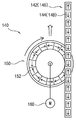
도 3은 도 1에 도시된 메인 프레임을 설명하기 위한 개략적인 평면도이다.FIG. 3 is a schematic plan view for explaining the main frame illustrated in FIG. 1.
도 3을 참조하면, 상기 메인 프레임(102)은 대략 팔각형의 단면 구조를 가질 수 있다. 구체적으로, 상기 메인 프레임(102)은 전면(102A)과 후면(102B), 양쪽 측면들(102C) 및 상기 전면(102A)과 후면(102B) 그리고 상기 양쪽 측면들(102C) 사이의 모따기면들(chamfered surfaces; 102D)을 가질 수 있다. 상기 캐리지 모듈(110)은 상기 메인 프레임(102)의 전면(102A) 측에 배치될 수 있으며, 상기 메인 프레임(102)의 후면(102B)에는 상기 메인 프레임(102)을 클린룸의 벽면에 고정시키기 위한 고정 브래킷들(106)이 배치될 수 있다.Referring to FIG. 3, the
본 발명의 일 실시예에 따르면, 상기 가동 프레임(104)은 상기 메인 프레임(102)의 후면(102B)을 제외한 나머지 외측면들을 감싸도록 구성될 수 있으며, 상기 부상 레일들(120)은 상기 모따기면들(102D) 상에 배치될 수 있다. 특히, 상기 모따기면들(102D) 중 하나 상에는 상기 캐리지 모듈(110)이 상기 메인 프레임(102)의 중심축을 기준으로 회전하는 것을 방지하기 위하여 두 개의 부상 레일들(120)이 서로 직교하도록 배치될 수 있다.According to an embodiment of the present invention, the
또한, 상기 타워 리프트(100)는 상기 캐리지 모듈(110)의 좌우 진동을 감소시키기 위하여 도 2에 도시된 바와 같이 상기 가동 프레임(104)의 상부와 하부에 각각 부상 유닛들(122)을 장착할 수 있다. 즉, 상기 부상 레일들(120)에 대응하여 상하 두 개의 부상 유닛들(122)이 각각 마련될 수 있으며, 이에 따라 상기 타워 리프트(100)는 다섯 개의 부상 레일들(120)과 열 개의 부상 유닛들(122)을 구비할 수 있다.In addition, the
상기 부상 유닛들(122)로는 전자기력을 발생시키기 위한 전자석들이 사용될 수 있으며, 도시되지는 않았으나, 상기 가동 프레임(104)에는 상기 부상 레일들(120)과 상기 부상 유닛들(120) 사이의 간격을 측정하기 위한 센서들(미도시)이 상기 부상 유닛들(122)에 인접하도록 장착될 수 있다. 또한, 도시되지는 않았으나, 상기 타워 리프트(100)는 상기 센서들에 의해 측정된 간격들에 기초하여 상기 부상 유닛들(122)로 인가되는 전원을 제어하기 위한 제어부(미도시)를 포함할 수 있다.Electromagnets for generating electromagnetic force may be used as the floating
또한, 상기 가동 프레임(104)에는 복수의 보조 휠들(108)이 장착될 수 있다. 예를 들면, 도 2에 도시된 바와 같이 각각의 부상 유닛들(122)에 인접하도록 보조 휠들(108)이 상기 가동 프레임(104)에 장착될 수 있다. 상기 보조 휠들(108)은 상기 부상 유닛들(122)과 상기 부상 레일들(120)이 서로 접촉되는 것을 방지하기 위해 사용될 수 있으며, 상기 부상 레일들(120)로부터 소정 간격 이격될 수 있다.In addition, the
본 발명의 일 실시예에 따르면, 상기 타워 리프트(100)는 상기 메인 프레임(102)의 측면을 따라 수직 방향으로 연장하는 전원 공급 케이블(130)과, 상기 가동 프레임(104)에 장착되며 상기 전원 공급 케이블(130)로부터 비접촉 방식으로 전력을 전송받고 상기 캐리지 모듈(110)과 상기 부상 유닛들(122)에 전원을 인가하는 픽업 유닛(134)을 구비할 수 있다.According to one embodiment of the invention, the
예를 들면, 상기 메인 프레임(102)의 양쪽 측면들(102C) 상에는 각각 전원 공급 케이블들(130)을 지지하기 위한 케이블 브래킷들(132)이 장착될 수 있으며, 상기 가동 프레임(104)에는 상기 전원 공급 케이블들(130)을 감싸도록 픽업 유닛들(134)이 장착될 수 있다. 특히, 상세히 도시되지는 않았으나, 상기 가동 프레임(104)의 상부와 하부에 각각 픽업 유닛들(134)이 장착될 수 있다. 즉, 상기 가동 프레임(104)에는 네 개의 픽업 유닛들(134)이 장착될 수 있다.For example,
한편, 상기 캐리지 모듈(110)은 이송 대상물을 픽업하기 위한 이송 로봇을 포함할 수 있다. 도시된 바에 의하면, 스카라 로봇이 구비되고 있으나 상기 이송 로봇의 종류는 다양하게 변경 가능하므로 이에 의해 본 발명의 범위가 제한되지는 않을 것이다.On the other hand, the
본 발명의 일 실시예에 따르면, 상기 타워 리프트(100)는 상기 캐리지 모듈(110)을 비접촉 방식으로 이동시키기 위한 비접촉 구동 모듈(140)을 구비할 수 있다.According to an embodiment of the present invention, the
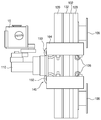
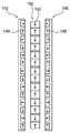
도 4는 도 1에 도시된 비접촉 구동 모듈을 설명하기 위한 개략적인 평면도이고, 도 5는 도 1에 도시된 비접촉 구동 모듈의 구동 레일들과 구동 휠을 설명하기 위한 개략적인 구성도이고, 도 6은 도 5에 도시된 구동 휠을 설명하기 위한 전개도이다.FIG. 4 is a schematic plan view illustrating the non-contact driving module shown in FIG. 1, FIG. 5 is a schematic diagram illustrating the driving rails and the driving wheel of the non-contact driving module shown in FIG. 1. 5 is an exploded view for explaining the driving wheel shown in FIG. 5.
도 4 내지 도 6을 참조하면, 상기 비접촉 구동 모듈(140)은, 상기 메인 프레임(102)의 전면(102A) 상에서 수직 방향으로 서로 평행하게 연장하며 수직 방향으로 배열된 제1 영구자석들(144)과 제2 영구자석들(148)을 각각 포함하는 한 쌍의 구동 레일들(142, 146)과, 상기 구동 레일들(142, 146)로부터 소정 간격 이격되도록 상기 구동 레일들(142, 146) 사이에 배치되며 원주 방향으로 배열된 제3 영구자석들(152)을 포함하는 구동 휠(150)과, 상기 구동 휠(150)을 회전시키기 위한 구동 유닛(160)을 포함할 수 있다. 특히, 상기 구동 휠(150)의 회전력과 상기 제1, 제2 및 제3 영구자석들(144, 148, 152) 사이의 자기력에 의해 추진력이 발생되도록 상기 제3 영구자석들(152) 중 적어도 하나가 상기 제1 및 제2 영구자석들(144, 148) 사이에 배치될 수 있다.4 to 6, the
일 예로서, 상기 비접촉 구동 모듈(140)은 도 2에 도시된 바와 같이 상하 두 개의 구동 휠들(150)과 상기 구동 휠들(150)에 연결된 상하 두 개의 구동 유닛들(160)을 구비할 수 있다. 그러나, 상기 구동 휠들(150)과 구동 유닛들(160)의 개수는 다양하게 변경 가능하므로 이에 의해 본 발명의 범위가 제한되지는 않을 것이다.For example, the
또한, 상기 구동 유닛들(160)은 회전력을 제공하는 모터를 각각 포함할 수 있으며, 상기 비접촉 구동 모듈(140)은 상기 구동 모듈(160)의 모터들의 회전축들에 제동력을 인가하기 위한 제동 유닛들(162)을 포함할 수 있다. 예를 들면, 상기 제동 유닛들(162)로는 전자 브레이크가 사용될 수 있으며, 상기 전자 브레이크는 상기 캐리지 모듈(110)의 정지 상태를 유지하기 위하여 상기 회전축들에 제동력을 인가할 수 있다.In addition, the driving
특히, 도시되지는 않았으나, 일 예로서, 상기 전자 브레이크는 자기력을 발생시키는 코일과 상기 회전축에 제동력을 인가하기 위한 스프링을 구비할 수 있으며 상기 자기력을 이용하여 제동 상태를 해제할 수 있다. 따라서, 예상치 못한 원인으로 상기 타워 리프트(100)에 전원 공급이 차단되는 경우 상기 스프링에 의해 제동 상태가 유지될 수 있으므로 상기 타워 리프트(100)의 추락을 방지할 수 있다.In particular, although not shown, the electromagnetic brake may include a coil for generating a magnetic force and a spring for applying a braking force to the rotating shaft, and may release the braking state by using the magnetic force. Therefore, when the power supply to the
상기 구동 레일들(142, 146)의 제1 및 제2 영구자석들(144, 148)은 도 5 및 도 6에 도시된 바와 같이 N극과 S극이 수직 방향으로 배열되고 동일한 극성의 자극들(magnetic poles)이 서로 마주하도록 배치될 수 있다. 예를 들면, 실린더 형태의 제1 및 제2 영구자석들(144, 148)이 상기 제1 구동 레일(142, 146)과 제2 구동 레일에 각각 장착될 수 있다.As shown in FIGS. 5 and 6, the first and second
도 5 및 도 6에 도시된 바와 같이 상기 구동 휠(150)의 제3 영구자석들(152)은 N극과 S극이 원주 방향으로 배열되고 동일한 극성의 자극들이 서로 마주하도록 배치될 수 있다. 이때, 상기 제1 및 제3 영구자석들(144, 152) 사이 그리고 상기 제2 및 제3 영구자석들(148, 152) 사이의 자기력을 증가시키고 또한 상기 캐리지 모듈(110)의 위치 제어가 보다 용이하도록 도 6에 도시된 바와 같이 상기 제1 및 제2 영구자석들(144, 148)의 피치는 상기 제3 영구자석들(152)의 피치와 동일하게 구성될 수 있다. 한편, 상기 구동 휠(150)을 구성하는 상기 제3 영구자석들(152)의 개수는 다양하게 변경 가능하므로 이에 의해 본 발명의 범위가 제한되지는 않을 것이다.As shown in FIGS. 5 and 6, the third
도 7은 도 1에 도시된 비접촉 구동 모듈의 다른 예를 설명하기 위한 개략적인 구성도이고, 도 8은 도 7에 도시된 구동 휠을 설명하기 위한 전개도이다.FIG. 7 is a schematic configuration diagram illustrating another example of the non-contact driving module illustrated in FIG. 1, and FIG. 8 is an exploded view illustrating the driving wheel illustrated in FIG. 7.
도 7 및 도 8을 참조하면, 상기 구동 휠(150)은 원주 방향으로 배열된 제3 영구자석들(152)과 제4 영구자석들(154)을 포함할 수 있다. 상기 제3 및 제4 영구자석들(152, 154)은 상기 제1 및 제2 영구자석들(144, 148)과 마주하도록 상기 구동 휠(150)의 양측에 각각 장착될 수 있다.7 and 8, the
특히, 상기 제3 및 제4 영구자석들(152, 154)은 할바흐 배열(Halbach arrangement) 형태를 갖도록 배열될 수 있다. 즉, 상기 제1 및 제3 영구자석들(144, 152) 사이 그리고 상기 제2 및 제4 영구자석들(148, 154) 사이에서 할바흐 배열에 의해 자기장의 세기가 증가될 수 있으며, 이에 따라 상기 타워 리프트(100)의 추진력이 향상될 수 있다. 이때, 상기 구동 레일들(142, 146)의 제1 및 제2 영구자석들(144, 148)은 N극과 S극이 수직 방향으로 배열되고 동일한 극성의 자극들이 서로 마주하도록 배열될 수 있다.In particular, the third and fourth
도 9는 도 1에 도시된 비접촉 구동 모듈의 또 다른 예를 설명하기 위한 개략 적인 구성도이고, 도 10은 도 9에 도시된 구동 휠을 설명하기 위한 전개도이다.FIG. 9 is a schematic diagram illustrating another example of the non-contact driving module illustrated in FIG. 1, and FIG. 10 is a development view illustrating the driving wheel illustrated in FIG. 9.
도 9 및 도 10을 참조하면, 상기 제1 및 제2 영구 자석들(144, 148)은 상기 제1 및 제3 영구자석들(144, 152) 사이 그리고 상기 제2 및 제3 영구자석들(148, 152) 사이에서 자기장의 세기를 향상시키기 위하여 할바흐 배열 형태를 갖도록 배치될 수 있다. 이때, 상기 제3 영구자석들(152)은 N극과 S극이 원주 방향으로 배열되고 동일한 극성의 자극들이 서로 마주하도록 배열될 수 있다.9 and 10, the first and second
도 11은 도 1에 도시된 비접촉 구동 모듈의 또 다른 예를 설명하기 위한 개략적인 구성도이고, 도 12는 도 11에 도시된 구동 휠을 설명하기 위한 전개도이다.FIG. 11 is a schematic diagram illustrating another example of the non-contact driving module illustrated in FIG. 1, and FIG. 12 is an exploded view illustrating the driving wheel illustrated in FIG. 11.
도 11 및 도 12를 참조하면, 상기 구동 휠(150)은 원주 방향으로 배열되는 제3 영구자석들(152)과 제4 영구자석들(154)을 포함할 수 있다. 상기 제3 및 제4 영구자석들(152, 154)은 상기 제1 및 제2 영구자석들(144, 148)과 마주하도록 상기 구동 휠(150)의 양쪽 측면들에 각각 장착될 수 있다.11 and 12, the
특히, 상기 제1 및 제2 영구자석들(144, 148)과 상기 제3 및 제4 영구자석들(152, 154)은 상기 제1 및 제3 영구자석들(144, 152) 사이 그리고 상기 제2 및 제4 영구자석들(148, 154) 사이에서 자기장의 세기를 증가시키기 위해 모두 할바흐 배열 형태를 갖도록 배열될 수 있다.In particular, the first and second
상술한 바와 같은 본 발명의 실시예들에 따르면, 타워 리프트(100)는 수직 방향으로 연장하는 메인 프레임(102)과, 상기 메인 프레임(102)을 감싸도록 구성되고 상기 메인 프레임(102)을 따라 수직 방향으로 이동 가능하게 구성된 가동 프레임(104)과, 상기 가동 프레임(104)을 상기 메인 프레임(102)으로부터 부상시키기 위한 복수의 부상 유닛들(122)과, 상기 가동 프레임(104)에 장착되고 물건 이송을 위한 캐리지 모듈(110)과, 비접촉 방식으로 추진력을 제공하는 비접촉 구동 모듈(140)을 포함할 수 있다.According to the embodiments of the present invention as described above, the
상기 비접촉 구동 모듈(140)은, 상기 메인 프레임(102) 상에서 수직 방향으로 서로 평행하게 연장하며 수직 방향으로 배열된 제1 영구자석들(144)과 제2 영구자석들(148)을 각각 포함하는 한 쌍의 구동 레일들(142, 146)과, 상기 구동 레일들(142, 146)로부터 소정 간격 이격되도록 상기 구동 레일들(142, 146) 사이에 배치되며 원주 방향으로 배열된 제3 영구자석들(152)을 포함하는 구동 휠(150)과, 상기 구동 휠(150)을 회전시키기 위한 구동 유닛(160)을 포함할 수 있다.The
상기와 같이 상기 가동 프레임(104)과 캐리지 모듈(110)은 부상 유닛들(122)에 의해 상기 메인 프레임(102)으로부터 부상된 상태에서 상기 비접촉 구동 모듈(140)에 의해 제공되는 추진력을 이용하여 수직 방향으로 이동될 수 있다. 따라서, 가이드 롤러들과 가이드 레일들을 이용하는 종래 기술의 타워 리프트와 비교하여 파티클 발생량이 충분히 감소될 수 있으며, 이에 따라 상기 타워 리프트(100)를 이용하는 클린룸들 내부의 청정도가 크게 향상될 수 있다.As described above, the
상기에서는 본 발명의 바람직한 실시예를 참조하여 설명하였지만, 해당 기술 분야의 숙련된 당업자는 하기의 청구범위에 기재된 본 발명의 사상 및 영역으로부터 벗어나지 않는 범위 내에서 본 발명을 다양하게 수정 및 변경시킬 수 있음을 이해할 수 있을 것이다.Although the above has been described with reference to the preferred embodiment of the present invention, those skilled in the art can variously modify and change the present invention without departing from the spirit and scope of the present invention described in the claims below. I can understand that.
100 : 타워 리프트 102 : 메인 프레임
104 : 가동 프레임 106 : 고정 브래킷
108 : 보조 휠 110 : 캐리지 모듈
120 : 부상 레일 122 : 부상 유닛
130 : 전원 공급 케이블 132 : 케이블 브래킷
134 : 픽업 유닛 140 : 비접촉 구동 모듈
142 : 제1 구동 레일 144 : 제1 영구자석
146 : 제2 구동 레일 148 : 제2 영구자석
150 : 구동 휠 152 : 제3 영구자석
154 : 제4 영구자석 160 : 구동 유닛100: tower lift 102: main frame
104: movable frame 106: fixing bracket
108: auxiliary wheel 110: carriage module
120: floating rail 122: floating unit
130: power supply cable 132: cable bracket
134: pickup unit 140: non-contact drive module
142: first drive rail 144: first permanent magnet
146: second drive rail 148: second permanent magnet
150: driving wheel 152: third permanent magnet
154: fourth permanent magnet 160: drive unit
Claims (20)
상기 메인 프레임을 감싸도록 구성되고 상기 메인 프레임을 따라 수직 방향으로 이동 가능하게 구성된 가동 프레임;
상기 가동 프레임을 상기 메인 프레임으로부터 부상시키기 위한 복수의 부상 유닛들;
상기 가동 프레임에 장착되고 물건 이송을 위한 캐리지 모듈;
상기 메인 프레임 상에서 수직 방향으로 서로 평행하게 연장하며 수직 방향으로 배열된 제1 영구자석들과 제2 영구자석들을 각각 포함하는 한 쌍의 구동 레일들;
상기 구동 레일들로부터 소정 간격 이격되도록 상기 구동 레일들 사이에 배치되며 원주 방향으로 배열된 제3 영구자석들을 포함하는 구동 휠; 및
상기 구동 휠을 회전시키기 위한 구동 유닛을 포함하되,
상기 메인 프레임은 전면, 후면, 양쪽 측면들 및 상기 전면과 후면 그리고 상기 측면들 사이의 모따기면들을 갖고, 상기 부상 유닛들은 상기 모따기면들과 마주하도록 상기 가동 프레임에 장착되는 것을 특징으로 하는 것을 특징으로 하는 타워 리프트.A main frame extending in the vertical direction;
A movable frame configured to surround the main frame and configured to be movable in a vertical direction along the main frame;
A plurality of floating units for floating the movable frame from the main frame;
A carriage module mounted to the movable frame and configured to transfer goods;
A pair of driving rails each extending on the main frame in parallel to each other in a vertical direction and including first permanent magnets and second permanent magnets arranged in a vertical direction;
A drive wheel disposed between the drive rails and spaced apart from the drive rails, the drive wheel including third permanent magnets arranged in a circumferential direction; And
Including a drive unit for rotating the drive wheel,
The main frame has a front surface, a rear surface, both sides, and chamfer surfaces between the front surface and the rear surface, and the floating units are mounted to the movable frame to face the chamfer surfaces. Tower lift.
상기 제3 및 제4 영구자석들은 상기 제1 및 제2 영구자석들과 마주하도록 상기 구동 휠의 양측에 각각 배치되며,
상기 제3 및 제4 영구자석들은 할바흐 배열 형태를 갖는 것을 특징으로 하는 타워 리프트.The method of claim 10, wherein the drive wheel further comprises a fourth permanent magnets arranged in the circumferential direction,
The third and fourth permanent magnets are respectively disposed on both sides of the drive wheel to face the first and second permanent magnets,
And the third and fourth permanent magnets have a Halbach arrangement.
상기 제3 영구자석들은 N극과 S극이 원주 방향으로 배열되고 동일한 극성의 자극들이 서로 마주하도록 배열되는 것을 특징으로 하는 타워 리프트.The method of claim 8, wherein the first and second permanent magnets have a Halbach arrangement,
And the third permanent magnets are arranged such that the north pole and the south pole are arranged in the circumferential direction, and the magnetic poles of the same polarity face each other.
상기 제3 및 제4 영구자석들은 상기 제1 및 제2 영구자석들과 마주하도록 상기 구동 휠의 양측에 각각 배치되며,
상기 제1, 제2, 제3 및 제4 영구자석들은 할바흐 배열 형태를 갖는 것을 특징으로 하는 타워 리프트.The method of claim 10, wherein the drive wheel further comprises a fourth permanent magnets arranged in the circumferential direction,
The third and fourth permanent magnets are respectively disposed on both sides of the drive wheel to face the first and second permanent magnets,
And the first, second, third and fourth permanent magnets have a Halbach arrangement.
상기 가동 프레임에 장착되며 상기 전원 공급 케이블로부터 비접촉 방식으로 전력을 전송받고 상기 캐리지 모듈로 전원을 인가하는 픽업 유닛을 더 포함하는 것을 특징으로 하는 타워 리프트.The apparatus of claim 8, further comprising: a power supply cable extending in a vertical direction along a side of the main frame; And
And a pickup unit mounted to the movable frame and receiving power from the power supply cable in a non-contact manner and applying power to the carriage module.
상기 부상 유닛들은 상기 부상 레일들과 마주하도록 상기 가동 프레임에 장착되며 자기력을 이용하여 상기 가동 프레임을 상기 메인 프레임으로부터 부상시키는 것을 특징으로 하는 타워 리프트.According to claim 8, On the chamfered surface floating rails extending in the vertical direction,
And the floating units are mounted to the movable frame so as to face the floating rails and lift the movable frame from the main frame using magnetic force.
Priority Applications (3)
| Application Number | Priority Date | Filing Date | Title |
|---|---|---|---|
| KR1020170106671A KR102020232B1 (en) | 2017-08-23 | 2017-08-23 | Tower lift |
| US16/106,602 US10854489B2 (en) | 2017-08-23 | 2018-08-21 | Tower lift |
| CN201810962765.1A CN109422167B (en) | 2017-08-23 | 2018-08-22 | Tower type elevator |
Applications Claiming Priority (1)
| Application Number | Priority Date | Filing Date | Title |
|---|---|---|---|
| KR1020170106671A KR102020232B1 (en) | 2017-08-23 | 2017-08-23 | Tower lift |
Publications (2)
| Publication Number | Publication Date |
|---|---|
| KR20190021659A KR20190021659A (en) | 2019-03-06 |
| KR102020232B1 true KR102020232B1 (en) | 2019-09-10 |
Family
ID=65437974
Family Applications (1)
| Application Number | Title | Priority Date | Filing Date |
|---|---|---|---|
| KR1020170106671A Active KR102020232B1 (en) | 2017-08-23 | 2017-08-23 | Tower lift |
Country Status (3)
| Country | Link |
|---|---|
| US (1) | US10854489B2 (en) |
| KR (1) | KR102020232B1 (en) |
| CN (1) | CN109422167B (en) |
Families Citing this family (11)
| Publication number | Priority date | Publication date | Assignee | Title |
|---|---|---|---|---|
| KR102247447B1 (en) * | 2019-10-11 | 2021-04-30 | 세메스 주식회사 | Object transport apparatus |
| KR102596285B1 (en) * | 2020-03-30 | 2023-11-01 | 세메스 주식회사 | Tower Lift, Driving Method for tower lift and Machine readable medium |
| KR102548295B1 (en) * | 2020-10-07 | 2023-06-27 | 세메스 주식회사 | Braking unit and tower life |
| KR102504683B1 (en) * | 2020-12-03 | 2023-02-27 | 세메스 주식회사 | Carriage apparatus and tower lifting system including the same |
| KR102896276B1 (en) * | 2021-07-13 | 2025-12-04 | 세메스 주식회사 | Tower Lift and Driving Method for tower lift |
| EP4541749A1 (en) | 2021-11-05 | 2025-04-23 | Otis Elevator Company | Safety brake system |
| KR102702320B1 (en) * | 2021-12-28 | 2024-09-04 | 세메스 주식회사 | Tower Lift of Magnetic Levitation |
| KR102670560B1 (en) * | 2021-12-28 | 2024-05-29 | 세메스 주식회사 | Carriage Guide System and Carriage System using thereof for Magnetic Levitation Tower Lift |
| US12570502B2 (en) | 2022-03-11 | 2026-03-10 | Semes Co., Ltd. | Braking unit and tower lift |
| KR102727088B1 (en) * | 2022-11-18 | 2024-11-06 | 세메스 주식회사 | Brake device and towerlift comprising the brake device |
| KR102780834B1 (en) * | 2022-12-20 | 2025-03-12 | 세메스 주식회사 | Tower lift |
Citations (2)
| Publication number | Priority date | Publication date | Assignee | Title |
|---|---|---|---|---|
| JP2012017776A (en) * | 2010-07-06 | 2012-01-26 | Tsubakimoto Chain Co | Magnetic driving force converter |
| JP2013215021A (en) * | 2012-03-30 | 2013-10-17 | Kogakuin Univ | Electromagnetic induction device |
Family Cites Families (9)
| Publication number | Priority date | Publication date | Assignee | Title |
|---|---|---|---|---|
| JP2500546B2 (en) * | 1991-05-24 | 1996-05-29 | フジテック株式会社 | Elevator device |
| JPH08119599A (en) * | 1994-10-20 | 1996-05-14 | Kajima Corp | Vertical carrier non-contact guide mechanism |
| US6758146B2 (en) * | 2001-06-29 | 2004-07-06 | The Regents Of The University Of California | Laminated track design for inductrack maglev systems |
| KR101416903B1 (en) * | 2007-09-06 | 2014-07-08 | 엘지디스플레이 주식회사 | Stocker |
| CN102653247A (en) * | 2011-03-04 | 2012-09-05 | 吴小平 | Blade-adjusted-type permanent magnetic suspension technology |
| US9116198B2 (en) * | 2012-02-10 | 2015-08-25 | Memsic, Inc. | Planar three-axis magnetometer |
| US10400761B2 (en) * | 2015-01-29 | 2019-09-03 | Weatherford Technology Holdings, Llc | Long stroke pumping unit |
| KR101731260B1 (en) | 2015-09-17 | 2017-04-28 | 주식회사 에스에프에이 | Vertical Transport Systems |
| CN206126572U (en) * | 2016-08-16 | 2017-04-26 | 常熟市通润电梯厂有限公司 | Three passenger lift that open door |
-
2017
- 2017-08-23 KR KR1020170106671A patent/KR102020232B1/en active Active
-
2018
- 2018-08-21 US US16/106,602 patent/US10854489B2/en active Active
- 2018-08-22 CN CN201810962765.1A patent/CN109422167B/en active Active
Patent Citations (2)
| Publication number | Priority date | Publication date | Assignee | Title |
|---|---|---|---|---|
| JP2012017776A (en) * | 2010-07-06 | 2012-01-26 | Tsubakimoto Chain Co | Magnetic driving force converter |
| JP2013215021A (en) * | 2012-03-30 | 2013-10-17 | Kogakuin Univ | Electromagnetic induction device |
Also Published As
| Publication number | Publication date |
|---|---|
| KR20190021659A (en) | 2019-03-06 |
| US10854489B2 (en) | 2020-12-01 |
| CN109422167A (en) | 2019-03-05 |
| CN109422167B (en) | 2020-09-04 |
| US20190067067A1 (en) | 2019-02-28 |
Similar Documents
| Publication | Publication Date | Title |
|---|---|---|
| KR102020232B1 (en) | Tower lift | |
| KR101854034B1 (en) | Contactless driving module and transfer apparatus having the same | |
| JP6165992B2 (en) | Magnetic levitation transport device | |
| KR102479920B1 (en) | semiconductor process equipment | |
| KR101386685B1 (en) | Apparatus for processing substrate | |
| KR101454302B1 (en) | Magnetically levitated transportation system for display manufacturing equipment | |
| KR102192244B1 (en) | Apparatus for transferring substrate | |
| KR101409524B1 (en) | Apparatus for transferring substrates | |
| KR102138321B1 (en) | Non-contact transfertation system using linear motors | |
| KR101960679B1 (en) | Roller Unit Containing Guide wheel and Pallet Transfer System using thereof | |
| KR102733538B1 (en) | Magnetic levitation system, carrier for magnetic levitation system, vacuum system, and method for transporting carrier | |
| WO2020167956A1 (en) | Modular material handling robot platform | |
| KR102575953B1 (en) | Magnetic levitation transfer apparatus | |
| KR20160108549A (en) | Substrate transport vacuum platform | |
| KR100790557B1 (en) | First-in, first-out buffer system | |
| KR20190049532A (en) | Non-contact vertical transportation system using linear motors | |
| CN112185876A (en) | Magnetic adsorption mechanism, evaporation device and electronic device manufacturing device | |
| CN114981471B (en) | Carrier transport system, carrier for substrate, vacuum processing equipment and method for transporting carrier in vacuum chamber | |
| KR20120137662A (en) | Traveling vacuum robot | |
| KR102721109B1 (en) | Magnetic levitation type driving apparatus and semiconductro manufacturing equipment including the same | |
| KR20100086412A (en) | Transferring apparatus | |
| KR20250090866A (en) | tranffer unit, substrate processing apparatus including same | |
| KR20140103427A (en) | Substrate transferring apparatus for large area deposition system | |
| KR20120073806A (en) | Apparatus for transferring substrate and noncontact transfer apparatus | |
| KR20210047995A (en) | System for transferring for manufacturing display device |
Legal Events
| Date | Code | Title | Description |
|---|---|---|---|
| A201 | Request for examination | ||
| PA0109 | Patent application |
St.27 status event code: A-0-1-A10-A12-nap-PA0109 |
|
| PA0201 | Request for examination |
St.27 status event code: A-1-2-D10-D11-exm-PA0201 |
|
| D13-X000 | Search requested |
St.27 status event code: A-1-2-D10-D13-srh-X000 |
|
| D14-X000 | Search report completed |
St.27 status event code: A-1-2-D10-D14-srh-X000 |
|
| E902 | Notification of reason for refusal | ||
| PE0902 | Notice of grounds for rejection |
St.27 status event code: A-1-2-D10-D21-exm-PE0902 |
|
| PG1501 | Laying open of application |
St.27 status event code: A-1-1-Q10-Q12-nap-PG1501 |
|
| E13-X000 | Pre-grant limitation requested |
St.27 status event code: A-2-3-E10-E13-lim-X000 |
|
| P11-X000 | Amendment of application requested |
St.27 status event code: A-2-2-P10-P11-nap-X000 |
|
| P13-X000 | Application amended |
St.27 status event code: A-2-2-P10-P13-nap-X000 |
|
| E701 | Decision to grant or registration of patent right | ||
| PE0701 | Decision of registration |
St.27 status event code: A-1-2-D10-D22-exm-PE0701 |
|
| GRNT | Written decision to grant | ||
| PR0701 | Registration of establishment |
St.27 status event code: A-2-4-F10-F11-exm-PR0701 |
|
| PR1002 | Payment of registration fee |
St.27 status event code: A-2-2-U10-U11-oth-PR1002 Fee payment year number: 1 |
|
| PG1601 | Publication of registration |
St.27 status event code: A-4-4-Q10-Q13-nap-PG1601 |
|
| PR1001 | Payment of annual fee |
St.27 status event code: A-4-4-U10-U11-oth-PR1001 Fee payment year number: 4 |
|
| PN2301 | Change of applicant |
St.27 status event code: A-5-5-R10-R13-asn-PN2301 St.27 status event code: A-5-5-R10-R11-asn-PN2301 |
|
| R18-X000 | Changes to party contact information recorded |
St.27 status event code: A-5-5-R10-R18-oth-X000 |
|
| PR1001 | Payment of annual fee |
St.27 status event code: A-4-4-U10-U11-oth-PR1001 Fee payment year number: 5 |
|
| PR1001 | Payment of annual fee |
St.27 status event code: A-4-4-U10-U11-oth-PR1001 Fee payment year number: 6 |
|
| PN2301 | Change of applicant |
St.27 status event code: A-5-5-R10-R13-asn-PN2301 St.27 status event code: A-5-5-R10-R11-asn-PN2301 |
|
| PR1001 | Payment of annual fee |
St.27 status event code: A-4-4-U10-U11-oth-PR1001 Fee payment year number: 7 |
|
| U11 | Full renewal or maintenance fee paid |
Free format text: ST27 STATUS EVENT CODE: A-4-4-U10-U11-OTH-PR1001 (AS PROVIDED BY THE NATIONAL OFFICE) Year of fee payment: 7 |
|
| P22-X000 | Classification modified |
St.27 status event code: A-4-4-P10-P22-nap-X000 |