KR102019739B1 - Improved connector device for hold-down structure - Google Patents
Improved connector device for hold-down structure Download PDFInfo
- Publication number
- KR102019739B1 KR102019739B1 KR1020140187144A KR20140187144A KR102019739B1 KR 102019739 B1 KR102019739 B1 KR 102019739B1 KR 1020140187144 A KR1020140187144 A KR 1020140187144A KR 20140187144 A KR20140187144 A KR 20140187144A KR 102019739 B1 KR102019739 B1 KR 102019739B1
- Authority
- KR
- South Korea
- Prior art keywords
- receptacle
- plug
- holddown
- insulator
- contact
- Prior art date
- Legal status (The legal status is an assumption and is not a legal conclusion. Google has not performed a legal analysis and makes no representation as to the accuracy of the status listed.)
- Active
Links
Images


Classifications
-
- H—ELECTRICITY
- H01—ELECTRIC ELEMENTS
- H01R—ELECTRICALLY-CONDUCTIVE CONNECTIONS; STRUCTURAL ASSOCIATIONS OF A PLURALITY OF MUTUALLY-INSULATED ELECTRICAL CONNECTING ELEMENTS; COUPLING DEVICES; CURRENT COLLECTORS
- H01R12/00—Structural associations of a plurality of mutually-insulated electrical connecting elements, specially adapted for printed circuits, e.g. printed circuit boards [PCB], flat or ribbon cables, or like generally planar structures, e.g. terminal strips, terminal blocks; Coupling devices specially adapted for printed circuits, flat or ribbon cables, or like generally planar structures; Terminals specially adapted for contact with, or insertion into, printed circuits, flat or ribbon cables, or like generally planar structures
- H01R12/70—Coupling devices
- H01R12/71—Coupling devices for rigid printing circuits or like structures
- H01R12/72—Coupling devices for rigid printing circuits or like structures coupling with the edge of the rigid printed circuits or like structures
- H01R12/73—Coupling devices for rigid printing circuits or like structures coupling with the edge of the rigid printed circuits or like structures connecting to other rigid printed circuits or like structures
-
- H—ELECTRICITY
- H01—ELECTRIC ELEMENTS
- H01R—ELECTRICALLY-CONDUCTIVE CONNECTIONS; STRUCTURAL ASSOCIATIONS OF A PLURALITY OF MUTUALLY-INSULATED ELECTRICAL CONNECTING ELEMENTS; COUPLING DEVICES; CURRENT COLLECTORS
- H01R12/00—Structural associations of a plurality of mutually-insulated electrical connecting elements, specially adapted for printed circuits, e.g. printed circuit boards [PCB], flat or ribbon cables, or like generally planar structures, e.g. terminal strips, terminal blocks; Coupling devices specially adapted for printed circuits, flat or ribbon cables, or like generally planar structures; Terminals specially adapted for contact with, or insertion into, printed circuits, flat or ribbon cables, or like generally planar structures
- H01R12/70—Coupling devices
- H01R12/71—Coupling devices for rigid printing circuits or like structures
- H01R12/72—Coupling devices for rigid printing circuits or like structures coupling with the edge of the rigid printed circuits or like structures
- H01R12/73—Coupling devices for rigid printing circuits or like structures coupling with the edge of the rigid printed circuits or like structures connecting to other rigid printed circuits or like structures
- H01R12/732—Printed circuits being in the same plane
-
- H—ELECTRICITY
- H01—ELECTRIC ELEMENTS
- H01R—ELECTRICALLY-CONDUCTIVE CONNECTIONS; STRUCTURAL ASSOCIATIONS OF A PLURALITY OF MUTUALLY-INSULATED ELECTRICAL CONNECTING ELEMENTS; COUPLING DEVICES; CURRENT COLLECTORS
- H01R13/00—Details of coupling devices of the kinds covered by groups H01R12/70 or H01R24/00 - H01R33/00
- H01R13/62—Means for facilitating engagement or disengagement of coupling parts or for holding them in engagement
- H01R13/629—Additional means for facilitating engagement or disengagement of coupling parts, e.g. aligning or guiding means, levers, gas pressure electrical locking indicators, manufacturing tolerances
- H01R13/631—Additional means for facilitating engagement or disengagement of coupling parts, e.g. aligning or guiding means, levers, gas pressure electrical locking indicators, manufacturing tolerances for engagement only
Landscapes
- Coupling Device And Connection With Printed Circuit (AREA)
- Details Of Connecting Devices For Male And Female Coupling (AREA)
Abstract
본 발명은 리셉터클 인슐레이터와, 상기 리셉터클 인슐레이터에 정해진 피치로 조립된 리셉터클 컨택트와, 상기 리셉터클 인슐레이터의 양단에 설치된 리셉터클 홀드다운을 구비한 리셉터클; 및 플러그 인슐레이터와, 상기 리셉터클 컨택트와 대응하는 피치로 상기 플러그 인슐레이터에 조립된 플러그 컨택트와, 상기 플러그 인슐레이터의 양단에 설치된 플러그 홀드다운을 구비한 플러그;를 포함하고, 상기 리셉터클과 상기 플러그 간의 체결시 상기 리셉터클 컨택트와 상기 플러그 컨택트가 일대일 접촉을 하는 동시에 상기 리셉터클 홀드다운과 상기 플러그 홀드다운이 서로 계합하고, 상기 리셉터클 홀드다운 및 상기 플러그 홀드다운 중 어느 하나는 상기 계합 시 탄성적으로 변형되어 다른 하나에 록킹되는 변위 암 부재를 구비하고, 상기 변위 암 부재는, 커넥터의 높이 방향으로 연장된 제1 변위 암과, 상기 제1 변위 암의 일부가 구부러져서 형성된 폴딩부와, 상기 폴딩부로부터 일체로 연장되고 상기 제1 변위 암으로부터 이격 형성된 제2 변위 암을 가진 것을 특징으로 하는 커넥터 장치를 개시한다.The present invention provides a receptacle including a receptacle insulator, a receptacle contact assembled at a predetermined pitch to the receptacle insulator, and a receptacle holddown provided at both ends of the receptacle insulator; And a plug having a plug insulator, a plug contact assembled to the plug insulator at a pitch corresponding to the receptacle contact, and a plug hold down provided at both ends of the plug insulator. The receptacle contact and the plug contact make a one-to-one contact, and at the same time, the receptacle holddown and the plug holddown engage each other, and one of the receptacle holddown and the plug holddown is elastically deformed during the engagement and the other And a displacement arm member locked in the lock, wherein the displacement arm member includes a first displacement arm extending in a height direction of the connector, a folding portion formed by bending a portion of the first displacement arm, and integrally from the folding portion. A second extending and spaced apart from the first displacement arm Disclosed is a connector device having a displacement arm.
Description
본 발명은 커넥터 장치에 관한 것으로서, 더욱 상세하게는 소형화 및 저배화커넥터에 적합한 구조의 홀드다운을 구비한 커넥터 장치에 관한 것이다.BACKGROUND OF THE INVENTION 1. Field of the Invention The present invention relates to a connector device, and more particularly, to a connector device having a holddown of a structure suitable for miniaturized and low-profile connectors.
커넥터 장치는 회로기판과 회로기판, 또는 회로기판과 전자부품을 FPCB 등을 이용하여 전기적으로 접속하기 위한 용도로 사용된다.A connector device is used for the purpose of electrically connecting a circuit board and a circuit board, or a circuit board and an electronic component using an FPCB or the like.
근래에 들어 커넥터 장치는 휴대용 단말 등의 회로기판에 널리 적용되고 있으며, 전자기기의 소형화 추세에 부응하도록 경박단소화가 요구되고 있다. 이와 더불어 회로기판에 실장되는 전자소자의 밀도가 높아짐에 따라 커넥터 장치에 구비되는 컨택트(Contact)의 수도 많아지고 컨택트 간의 배열 피치(Pitch) 또한 매우 좁게 설계되는 추세에 있다.In recent years, connector devices have been widely applied to circuit boards, such as portable terminals, and are required to be light and thin in order to meet the miniaturization trend of electronic devices. In addition, as the density of electronic devices mounted on a circuit board increases, the number of contacts provided in the connector device increases, and the arrangement pitch between the contacts is also very narrow.
통상적으로 커넥터 장치는 다수의 리셉터클 컨택트(Receptacle Contact)가 리셉터클 인슐레이터(Receptacle Insulator)에 정해진 피치로 조립된 리셉터클과, 상기 리셉터클 컨택트와 일대일 접촉하는 다수의 플러그 컨택트(Plug Contact)가 플러그 인슐레이터(Plug Insulator)에 조립된 플러그로 구성된다.In general, a connector device includes a receptacle in which a plurality of receptacle contacts are assembled at a predetermined pitch in a receptacle insulator, and a plurality of plug contacts in one-to-one contact with the receptacle contact are plug insulators. It is composed of plugs assembled in
리셉터클 컨택트와 플러그 컨택트는 각각 리셉터클측 케이블과 플러그측 케이블에 연결되거나 회로기판에 실장된다. 리셉터클에 플러그가 끼워져서 리셉터클 컨택트와 플러그 컨택트가 상호 접촉하여 도통되었을 때 리셉터클측 케이블과 플러그측 케이블 또는 회로기판들의 회로가 전기적으로 연결된다.The receptacle contact and the plug contact are respectively connected to the receptacle side cable and the plug side cable or mounted on a circuit board. When the plug is inserted into the receptacle and the receptacle contact and the plug contact are brought into contact with each other, the circuit of the receptacle side cable and the plug side cable or circuit boards is electrically connected.
상기와 같은 구성을 가진 커넥터 장치의 접속 신뢰성을 높이기 위해서는 리셉터클과 플러그 간의 체결 시 록킹 상태를 고정할 수 있는 기술적 수단이 마련되어야 한다.In order to increase the connection reliability of the connector device having the configuration described above, a technical means for fixing the locking state when the receptacle and the plug are fastened should be provided.
이와 관련하여 일본특허 제3940387호에는 커넥터의 실장 강화용으로 사용되는 홀드다운을 통해 록킹이 이루어지고 감합이 확실히 행해졌을 때 명료한 클릭감을 얻을 수 있는 커넥터에 관한 기술이 게재되어 있다. 일본특허 제3940387호는 탄성 변형을 하는 한 쌍의 유지 암을 플러그와 리셉터클에 각각 구비하고, 상기 플러그의 유지 암에 마련된 돌기가 상기 리셉터클의 유지 암에 마련된 돌기에 접촉하며 통과하는 과정에서 부하가 작용하고 돌기 통과 완료 시 록킹이 되어 무부하 상태가 되는 홀드다운 구조를 개시하고 있다.In this regard, Japanese Patent No. 3940387 discloses a technology relating to a connector which can obtain a clear click feeling when locking is performed through a holddown used for strengthening the mounting of a connector and a fitting is securely performed. Japanese Patent No. 3940387 has a pair of retaining arms which are elastically deformed in the plug and the receptacle, respectively, and the load is applied in the process of the projections provided on the retaining arms of the plugs contacting and passing through the projections provided on the retaining arms of the receptacle. A holddown structure is disclosed which is locked when the protrusion is completed and the protrusion is completed and becomes no-load.
하지만, 일본특허 제3940387호에 개시된 홀드다운은 유지 암이 단순히 커넥터의 높이 방향으로만 연장된 구조로 인해 충분한 변위 암 길이를 확보하게 되면 커넥터의 소형화 및 저배화 설계에 한계가 있고, 소형화 및 저배화 설계 시 변위 암의 길이가 제한적이어서 소성변형이나 마모가 발생하여 접촉 신뢰성의 확보가 어려운 단점이 있다.However, the holddown disclosed in Japanese Patent No. 3940387 has a limitation in the miniaturization and low-profile design of the connector when the retaining arm simply secures a sufficient displacement arm length due to the structure extending only in the height direction of the connector. In the design of fire extinguishing, there is a disadvantage in that it is difficult to secure contact reliability due to plastic deformation or wear due to the limited length of the displacement arm.
본 발명은 상기와 같은 문제점을 해결하기 위해 창안된 것으로서, 커넥터의 실장 강도 강화용으로 사용되는 홀드다운을 활용하여 컨택트 외에 추가적인 접속 수단을 구현하고, 커넥터의 높이 방향 및 피치 방향으로 변위 암을 확보할 수 있어 소형화 및 저배화 설계 적용이 가능하며, 소성변형 방지를 통해 접촉 신뢰성 확보가 가능한 구조의 홀드다운을 구비한 커넥터 장치를 제공하는 데 그 목적이 있다.The present invention was devised to solve the above problems, and implements an additional connection means in addition to the contact by using the hold down used to strengthen the mounting strength of the connector, and secures the displacement arm in the height direction and pitch direction of the connector The purpose of the present invention is to provide a connector device having a holddown having a structure capable of miniaturization and low magnification design, and ensuring contact reliability through plastic deformation prevention.
상기와 같은 목적을 달성하기 위해 본 발명은 리셉터클 인슐레이터와, 상기 리셉터클 인슐레이터에 정해진 피치로 조립된 리셉터클 컨택트와, 상기 리셉터클 인슐레이터의 양단에 설치된 리셉터클 홀드다운을 구비한 리셉터클; 및 플러그 인슐레이터와, 상기 리셉터클 컨택트와 대응하는 피치로 상기 플러그 인슐레이터에 조립된 플러그 컨택트와, 상기 플러그 인슐레이터의 양단에 설치된 플러그 홀드다운을 구비한 플러그;를 포함하고, 상기 리셉터클과 상기 플러그 간의 체결시 상기 리셉터클 컨택트와 상기 플러그 컨택트가 일대일 접촉을 하는 동시에 상기 리셉터클 홀드다운과 상기 플러그 홀드다운이 서로 계합하고, 상기 리셉터클 홀드다운 및 상기 플러그 홀드다운 중 어느 하나는 상기 계합 시 탄성적으로 변형되어 다른 하나에 록킹되는 변위 암 부재를 구비하고, 상기 변위 암 부재는, 커넥터의 높이 방향으로 연장된 제1 변위 암과, 상기 제1 변위 암의 일부가 구부러져서 형성된 폴딩부와, 상기 폴딩부로부터 일체로 연장되고 상기 제1 변위 암으로부터 이격 형성된 제2 변위 암을 가진 것을 특징으로 하는 커넥터 장치를 제공한다.To achieve the above object, the present invention provides a receptacle having a receptacle insulator, a receptacle contact assembled to a predetermined pitch on the receptacle insulator, and a receptacle hold down provided at both ends of the receptacle insulator; And a plug having a plug insulator, a plug contact assembled to the plug insulator at a pitch corresponding to the receptacle contact, and a plug hold down provided at both ends of the plug insulator. The receptacle contact and the plug contact make a one-to-one contact, and at the same time, the receptacle holddown and the plug holddown engage each other, and one of the receptacle holddown and the plug holddown is elastically deformed during the engagement and the other And a displacement arm member locked in the lock, wherein the displacement arm member includes a first displacement arm extending in a height direction of the connector, a folding portion formed by bending a portion of the first displacement arm, and integrally from the folding portion. A second extending and spaced apart from the first displacement arm Provided is a connector device having a displacement arm.
상기 제2 변위 암의 단부에는 상기 커넥터의 내측 방향으로 볼록한 형상을 가진 굴곡부가 형성되고, 상기 리셉터클 홀드다운 및 상기 플러그 홀드다운 중 다른 하나에는 상기 굴곡부가 계합될 수 있는 체결홈이 형성될 수 있다.A bent portion having a convex shape in the inward direction of the connector may be formed at an end of the second displacement arm, and a fastening groove for engaging the bent portion may be formed at the other one of the receptacle holddown and the plug holddown. .
상기 변위 암 부재는 상기 플러그 홀드다운에 구비되고, 상기 리셉터클 홀드다운에 있어서, 상기 플러그 홀드다운의 접촉이 시작되는 지점에는 상기 굴곡부가 슬라이딩될 수 있는 라운드면이 마련될 수 있다.The displacement arm member may be provided in the plug holddown, and in the receptacle holddown, a round surface on which the curved portion may slide may be provided at a point where the contact of the plug holddown starts.
상기 리셉터클 홀드다운은, 상기 리셉터클 인슐레이터의 길이방향 양단 측벽의 바깥면에 배치되는 지지 플레이트와, 상기 지지 플레이트의 한쪽 가장자리단으로부터 연장되어 상기 측벽의 상단을 감싸면서 상기 측벽의 안쪽면에 접하도록 배치되는 클립부를 구비할 수 있다.The receptacle holddown is disposed to be in contact with an inner surface of the sidewall while covering a top end of the sidewall extending from one edge end of the support plate and a support plate disposed on an outer surface of both longitudinal sidewalls of the receptacle insulator. It can be provided with a clip portion.
상기 라운드면은 상기 클립부의 상단 모서리부분에 위치하고, 상기 클립부에 있어서, 상기 측벽과 대향하는 부분에 상기 체결홈이 형성될 수 있다.The round surface may be located at an upper edge portion of the clip portion, and the fastening groove may be formed at a portion of the clip portion that faces the side wall.
상기 클립부는 커넥터의 폭방향을 기준으로 상기 지지 플레이트에 비해 작은 치수를 갖되 상기 지지 플레이트의 중간 지점에 위치하는 것이 바람직하다.The clip portion has a smaller dimension than the support plate with respect to the width direction of the connector, but is preferably located at an intermediate point of the support plate.
상기 리셉터클 홀드다운은, 상기 지지 플레이트의 양단에서 각각 상기 커넥터의 길이 방향으로 연장되어 상기 리셉터클 인슐레이터에 조립된 고정부를 구비할 수 있다.The receptacle holddown may include fixing parts assembled at the both ends of the support plate in the longitudinal direction of the connector and assembled to the receptacle insulator.
상기 리셉터클 홀드다운은, 상기 고정부로부터 상기 커넥터의 폭방향으로 돌출되어 상기 리셉터클 인슐레이터의 외부로 노출된 실장부를 구비할 수 있다.The receptacle holddown may include a mounting portion protruding from the fixing portion in the width direction of the connector and exposed to the outside of the receptacle insulator.
상기 플러그 홀드다운은, 상기 플러그 인슐레이터의 길이방향 양단 측벽에 인접한 체결 선단면을 각각 덮도록 배치되는 지지 플레이트와, 상기 지지 플레이트로부터 연장되어 상기 플러그 인슐레이터의 폭방향 양단면을 각각 감싸는 제1 홀더와, 상기 지지 플레이트로부터 연장되어 상기 플러그 인슐레이터의 길이방향 단부 바깥면을 지지하되 서로 이격된 한 쌍의 제2 홀더를 구비하고, 상기 한 쌍의 제2 홀더 사이에 상기 변위 암 부재가 위치하는 것이 바람직하다.The plug holddown may include a support plate disposed to cover fastening front ends adjacent to both longitudinal sidewalls of the plug insulator, and first holders extending from the support plate and surrounding both end surfaces in the width direction of the plug insulator, respectively. And a pair of second holders extending from the support plate to support the longitudinal end outer surface of the plug insulator and spaced apart from each other, wherein the displacement arm member is positioned between the pair of second holders. Do.
상기 리셉터클 컨택트와 상기 플러그 컨택트는 각각 상기 리셉터클 인슐레이터와 상기 플러그 인슐레이터의 길이방향을 따라 양편에 열을 지어 배치되고, 상기 리셉터클과 상기 플러그는 상기 리셉터클 인슐레이터 및 상기 플러그 인슐레이터의 높이 방향으로 체결되어 서로 형합될 수 있다.The receptacle contact and the plug contact are arranged in rows on both sides along the longitudinal direction of the receptacle insulator and the plug insulator, respectively, and the receptacle and the plug are fastened in the height direction of the receptacle insulator and the plug insulator, respectively, Can be.
상기 리셉터클 홀드다운과 상기 플러그 홀드다운은 계합 시 서로 전기적으로 연결되는 것이 바람직하다.Preferably, the receptacle holddown and the plug holddown are electrically connected to each other during engagement.
본 발명에 따르면 커넥터 장치는 다음과 같은 효과를 가진다.According to the present invention, the connector device has the following effects.
첫째, 커넥터의 높이 방향 및 피치 방향으로 변위 암의 길이를 충분히 확보하여 커넥터의 소형화 및 저배화 설계 적용이 가능하며, 소성변형을 방지할 수 있다.First, it is possible to secure a sufficient length of the displacement arm in the height direction and pitch direction of the connector, it is possible to apply the miniaturization and low-profile design of the connector, it is possible to prevent plastic deformation.
둘째, 홀드다운이 인슐레이터의 단부를 감싸는 구조에 의해 커넥터의 파괴 강도를 향상시킬 수 있다.Second, the breakdown strength of the connector can be improved by the structure in which the holddown surrounds the end of the insulator.
셋째, 실장 강도 강화용으로 사용되는 홀드다운을 활용하여 컨택트 외에 추가적인 전기적 접속 수단을 구현할 수 있다. 리셉터클과 플러그 간의 체결 시 홀드다운들 간에 기계적인 록킹과 전기적인 접속이 동시에 이루어질 수 있으므로 커넥터의 구성을 단순화하는 것이 가능하다.Third, additional electrical connection means other than the contact may be implemented by using the holddown used for strengthening the mounting strength. When locking between the receptacle and plug, mechanical locking and electrical connection can be made simultaneously between the holddowns, thus simplifying the configuration of the connector.
넷째, 리셉터클 홀드다운과 플러그 홀드다운이 계합되는 부분의 폭과 길이를 고전류용 커넥터에 대응하도록 용이하게 설계할 수 있다.Fourth, the width and length of the portion where the receptacle holddown and plug holddown are engaged can be easily designed to correspond to the high current connector.
본 명세서에 첨부되는 다음의 도면들은 본 발명의 바람직한 실시예를 예시하는 것이며, 후술되는 발명의 상세한 설명과 함께 본 발명의 기술사상을 더욱 이해시키는 역할을 하는 것이므로, 본 발명은 그러한 도면에 기재된 사항에만 한정되어 해석되어서는 아니된다.
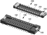
도 1은 본 발명의 바람직한 실시예에 따른 커넥터 장치의 구성을 도시한 분리 사시도,
도 2는 도 1의 결합 사시도,
도 3은 도 1에서 리셉터클의 구성을 도시한 분해 사시도,
도 4는 도 3에서 리셉터클 홀드다운의 구성을 상세히 보여주는 사시도,
도 5는 도 1에서 플러그의 구성을 도시한 분해 사시도,
도 6은 도 5에서 플러그 홀드다운의 구성을 상세히 보여주는 사시도,
도 7 내지 도 9는 리셉터클 홀드다운과 플러그 홀드다운의 결합 과정을 개략적으로 도시한 단면도이다.The following drawings attached to this specification are illustrative of the preferred embodiments of the present invention, and together with the detailed description of the invention to serve to further understand the technical spirit of the present invention, the present invention is a matter described in such drawings It should not be construed as limited to.
1 is an exploded perspective view showing the configuration of a connector device according to a preferred embodiment of the present invention;
2 is a perspective view of the combination of FIG.
3 is an exploded perspective view showing the configuration of the receptacle in FIG. 1;
4 is a perspective view showing in detail the configuration of the receptacle holddown in FIG.
5 is an exploded perspective view showing the configuration of the plug in FIG.
6 is a perspective view showing in detail the configuration of the plug holddown in FIG.
7 to 9 are cross-sectional views schematically illustrating a coupling process between a receptacle holddown and a plug holddown.
이하, 첨부된 도면을 참조하여 본 발명의 바람직한 실시예를 상세히 설명하기로 한다. 이에 앞서, 본 명세서 및 청구범위에 사용된 용어나 단어는 통상적이거나 사전적인 의미로 한정해서 해석되어서는 아니되며, 발명자는 그 자신의 발명을 가장 최선의 방법으로 설명하기 위해 용어의 개념을 적절하게 정의할 수 있다는 원칙에 입각하여 본 발명의 기술적 사상에 부합하는 의미와 개념으로 해석되어야만 한다. 따라서, 본 명세서에 기재된 실시예와 도면에 도시된 구성은 본 발명의 가장 바람직한 일 실시예에 불과할 뿐이고 본 발명의 기술적 사상을 모두 대변하는 것은 아니므로, 본 출원시점에 있어서 이들을 대체할 수 있는 다양한 균등물과 변형예들이 있을 수 있음을 이해하여야 한다.Hereinafter, exemplary embodiments of the present invention will be described in detail with reference to the accompanying drawings. Prior to this, terms or words used in the specification and claims should not be construed as having a conventional or dictionary meaning, and the inventors should properly explain the concept of terms in order to best explain their own invention. Based on the principle that can be defined, it should be interpreted as meaning and concept corresponding to the technical idea of the present invention. Therefore, the embodiments described in the specification and the drawings shown in the drawings are only the most preferred embodiment of the present invention and do not represent all of the technical idea of the present invention, various modifications that can be replaced at the time of the present application It should be understood that there may be equivalents and variations.
도 1은 본 발명의 바람직한 실시예에 따른 커넥터 장치의 구성을 도시한 분리 사시도이며, 도 2는 도 1의 결합 사시도이다.1 is an exploded perspective view showing the configuration of a connector device according to a preferred embodiment of the present invention, Figure 2 is a combined perspective view of FIG.
도 1 및 도 2를 참조하면, 본 발명의 바람직한 실시예에 따른 커넥터 장치는 양단에 리셉터클 홀드다운(103)을 구비한 리셉터클(100)과, 상기 리셉터클(100)에 체결되는 것으로서 양단에 플러그 홀드다운(203)을 구비하되 상기 플러그 홀드다운(203)에 변위 암 부재(도 7의 D 참조)가 마련된 구조를 가진 플러그(200)를 포함한다.1 and 2, a connector device according to a preferred embodiment of the present invention includes a
리셉터클(100)은 절연성 수지로 이루어진 리셉터클 인슐레이터(101)와, 리셉터클 인슐레이터(101)의 길이방향을 따라 일정한 피치로 조립된 다수의 리셉터클 컨택트(102)와, 리셉터클 인슐레이터(101)의 양단에 조립된 리셉터클 홀드다운(103)을 구비한다. 도 3에는 리셉터클(100)의 구성이 더욱 상세히 도시되어 있다.The
리셉터클 인슐레이터(101)는 전체적으로 장방형 몸체를 가진다. 리셉터클 인슐레이터(101)의 장방형 몸체는 그 높이 방향으로 삽입되는 플러그(200)를 수용하기 위한 내부공간을 구비한다.The
리셉터클 컨택트(102)는 플러그 컨택트(202)가 끼워질 수 있도록 실질적으로 'U'자 형상의 부분을 포함하는 형태로 구부러진 탄성 도전체에 의해 제공된다.The
리셉터클 홀드다운(103)은 리셉터클 인슐레이터(101)의 길이방향 양단에 각각 구비된다. 리셉터클 홀드다운(103)은 리셉터클(100)과 플러그(200) 간의 체결 시 플러그 홀드다운(203)과 계합하는 동시에 전기적으로 접속되는 탄성 도전체에 의해 구성된다.
도 4에 도시된 바와 같이 리셉터클 홀드다운(103)은 지지 플레이트(103a)와, 지지 플레이트(103a)의 한쪽 가장자리단으로부터 일체로 연장된 클립부(103b)를 구비한다.As shown in FIG. 4, the
지지 플레이트(103a)는 리셉터클 인슐레이터(101)의 길이방향 양단 측벽의 바깥면의 면적 내에 배치될 수 있는 길이와 높이를 가진다. 바람직하게, 리셉터클 홀드다운(103)은, 지지 플레이트(103a)의 양단에서 각각 커넥터의 피치 방향, 즉 리셉터클 인슐레이터(101)의 길이방향으로 연장되고 리셉터클 인슐레이터(101)에 조립되도록 끝부분이 꺽인 구조를 가진 고정부(103d,103e)와, 고정부(103d,103e)의 바깥쪽 가장자리단으로부터 커넥터의 폭방향으로 돌출되되 리셉터클 인슐레이터(101)의 외부로 노출되어 기판에 전기적으로 연결되는 실장부(103f,103g)를 구비한다.The
클립부(103b)는 커넥터의 폭방향을 기준으로 지지 플레이트(103a)에 비해 작은 치수를 가지며, 상기 지지 플레이트(103a)의 중간 지점에 위치한다. 도 4에 도시된 바와 같이 클립부(103b)는 지지 플레이트(103a)와 일체를 이루고, 리셉터클 인슐레이터(101)의 길이방향 양단 측벽의 상단을 감싸면서 상기 측벽의 안쪽면에 접하도록 배치된다. 이를 위해, 클립부(103b)는 실질적으로 'U'자 형상 부분의 포함하는 몸체를 가지며 굴곡진 부위, 즉 상단 모서리부분에는 후술하는 플러그 홀드다운(203)의 굴곡부(203i)가 접촉하면서 슬라이딩될 수 있는 라운드면을 구비하고, 상기 측벽과 대향하는 면에는 소정 형상의 체결홈(103c)을 구비한다. The
플러그(200)는 절연성 수지로 이루어지고 리셉터클 인슐레이터(101)와 형합 가능한 형태를 가진 플러그 인슐레이터(201)와, 리셉터클 컨택트(102)의 피치에 대응하도록 플러그 인슐레이터(201)에 일정한 피치로 조립된 다수의 플러그 컨택트(202)와, 플러그 인슐레이터(201)의 양단에 조립된 플러그 홀드다운(203)을 구비한다. 도 5에는 플러그(200)의 구성이 더욱 상세히 도시되어 있다.The
플러그 인슐레이터(201)는 리셉터클 인슐레이터(101)에 마련된 내부공간에 삽입 가능하도록 그에 대응하는 형상의 몸체를 가진다.The
플러그 컨택트(202)는 리셉터클 컨택트(102)에 끼워질 수 있도록 실질적으로 'U'자 형상의 부분을 포함하는 형태로 구부러진 탄성 도전체에 의해 제공된다.
플러그 홀드다운(203)은 플러그 인슐레이터(201)의 길이방향 양단에 각각 구비된다. 플러그 홀드다운(203)은 리셉터클(100)과 플러그(200) 간의 체결 시 리셉터클 홀드다운(103)과 계합하는 동시에 전기적으로 접속되는 탄성 도전체에 의해 구성된다.Plug holddowns 203 are provided at both ends of the
도 6에 도시된 바와 같이 플러그 홀드다운(203)은 지지 플레이트(203a), 제1 홀더(203b,203c), 제2 홀더(203d,203e) 및 변위 암 부재(D)를 구비한다.As shown in FIG. 6, the
지지 플레이트(203a)는 플러그 인슐레이터(201)의 길이방향 단부 주변에 배치된다. 보다 구체적으로, 지지 플레이트(203a)는 플러그 인슐레이터(201)의 길이방향 양단 측벽에 인접한 체결 선단면(201a)을 덮도록 배치된다. 여기서, 상기 체결 선단면(201a)은 리셉터클(100)과 플러그(200) 간의 체결 시 리셉터클 인슐레이터(101)의 내부공간 바닥면(101a)과 대향하게 되는 평면부를 지칭한다.The
제1 홀더(203b,203c)는 지지 플레이트(203a)의 양편에 한 쌍이 구비되어 서로 반대 방향으로 연장되되 지지 플레이트(203a)에 대하여 직각으로 밴딩된 구조를 가진다. 제1 홀더(203b,203c)는 플러그 인슐레이터(201)의 폭방향 양단면을 감싸도록 배치된다.A pair of
제2 홀더(203d,203e)는 상기 한 쌍의 제1 홀더(203b,203c) 사이에 위치한 지지 플레이트(203a)의 한쪽 가장자리단으로부터 한 쌍이 서로 나란히 연장된다. 아울러, 제2 홀더(203d,203e)는 지지 플레이트(203a)에 대하여 직각으로 밴딩되어 플러그 인슐레이터(201)의 길이방향 단부 바깥면을 지지한다.The pair of
변위 암 부재(D)는 지지 플레이트(203a)의 한쪽 가장자리단으로부터 일체로 연장되되 한 쌍의 제2 홀더(203d,203e) 사이에 위치한다. 구체적으로, 변위 암 부재(D)는 지지 플레이트(203a)로부터 직각으로 밴딩되어 커넥터의 높이 방향으로 연장된 제1 변위 암(203f)과, 상기 제1 변위 암(203f)의 일부가 실질적으로 'U'자형으로 구부러져서 형성된 폴딩부(203g)와, 상기 폴딩부(203g)로부터 일체로 연장되고 상기 제1 변위 암(203f)으로부터 상기 플러그 컨택트(202)의 피치 방향으로 이격된 제2 변위 암(203h)을 포함한다. 여기서, 상기 폴딩부 및 그에 일체화된 상기 변위 암의 수는 상기 예에 한정되지 않고 다양하게 변형 가능함은 물론이다.The displacement arm member D extends integrally from one edge end of the
상기와 같이 변위 암 부재(D)에는 적어도 하나 이상의 폴딩부(203g)가 마련되어 한정된 공간 내에서 커넥터의 높이 및 피치 방향으로 충분한 길이의 변위 암을 확보할 수 있다.As described above, the displacement arm member D is provided with at least one
변위 암 부재(D)에 있어서, 제2 변위 암(203h)의 단부에는 제1 변위 암(203f)으로부터 이격되는 방향으로 볼록한 형상을 가진 굴곡부(203i)가 구비된다. 굴곡부(203i)는 리셉터클(100)과 플러그(200) 간의 체결 시 리셉터클 홀드다운(103)에 마련된 체결홈(103c)에 계합된다.In the displacement arm member D, a bent portion 203i having a convex shape in the direction away from the
상기와 같은 구성을 가진 커넥터 장치는 리셉터클(100)과 플러그(200) 간의 체결시 플러그 인슐레이터(201)는 리셉터클 인슐레이터(101)에 커넥터의 높이 방향으로 삽입되어 형합되고, 각각의 플러그 컨택트(202)는 리셉터클 컨택트(102)와 일대일 접촉을 하게 되며, 리셉터클 홀드다운(103)과 플러그 홀드다운(203) 간에 기계적, 전기적 접속이 이루어지게 된다.In the connector device having the above configuration, when the
도 7 내지 도 9에는 리셉터클 홀드다운(103)과 플러그 홀드다운(203)의 결합 과정이 개략적으로 도시되어 있다. 도 7에 나타난 바와 같이 리셉터클(100)과 플러그(200)를 정렬시킨 상태에서 플러그(200)를 리셉터클(100)에 삽입하면, 도 8에 나타난 바와 같이 플러그 홀드다운(203)에 구비된 변위 암 부재(D)의 굴곡부(203i)가 리셉터클 홀드다운(103)의 라운드면에서 슬라이딩되면서 피치 방향으로 이동하고 이에 따라 제1 변위 암(203f) 및 제2 변위 암(203h)이 피치 방향으로 변형되어 변위가 발생하게 된다.7 to 9 schematically illustrate the coupling process of the receptacle holddown 103 and the
리셉터클(100)과 플러그(200) 간의 체결이 완료되면, 도 9에 도시된 바와 같이 플러그 홀드다운(203)의 굴곡부(203i)가 리셉터클 홀드다운(103)의 체결홈(103c)에 록킹되어 리셉터클 홀드다운(103)과 플러그 홀드다운(203) 간의 계합 상태가 유지된다.When the fastening between the
상기와 같은 과정을 통해 리셉터클 홀드다운(103)과 플러그 홀드다운(203)은 서로 기계적으로 록킹되는 동시에 전기적으로 접속된다. 이와 같이 기계적인 록킹 기능과 전기적인 접속 기능을 동시에 지원하는 플러그 홀드다운(203)의 변위 암 부재(D)와 리셉터클 홀드다운(103) 간의 결합 구조는 커넥터의 구성을 소형화, 저배화하고, 고전류 커넥터를 용이하게 구현할 수 있도록 하는 효과를 제공한다.Through the above process, the receptacle holddown 103 and the
이상에서 본 발명은 비록 한정된 실시예와 도면에 의해 설명되었으나, 본 발명은 이것에 의해 한정되지 않으며 본 발명이 속하는 기술분야에서 통상의 지식을 가진 자에 의해 본 발명의 기술사상과 아래에 기재될 특허청구범위의 균등범위 내에서 다양한 수정 및 변형이 가능함은 물론이다.Although the present invention has been described above by means of limited embodiments and drawings, the present invention is not limited thereto and will be described below by the person skilled in the art to which the present invention pertains. Of course, various modifications and variations are possible within the scope of the claims.
100: 리셉터클 101: 리셉터클 인슐레이터
102: 리셉터클 컨택트 103: 리셉터클 홀드다운
103a,203a: 지지 플레이트 103b: 클립부
103c: 체결홈 103d,103e: 고정부
103f,103g: 실장부 200: 플러그
201: 플러그 인슐레이터 202: 플러그 컨택트
203: 플러그 홀드다운 203b,203c: 제1 홀더
203d,203e: 제2 홀더 203f: 제1 변위 암
203g: 폴딩부 203h: 제2 변위 암
203i: 굴곡부 D: 탄성 암 부재100: receptacle 101: receptacle insulator
102: Receptacle Contact 103: Receptacle Holddown
103a and 203a:
103c:
103f, 103g: Mounting part 200: Plug
201: plug insulator 202: plug contact
203: Plug hold down 203b, 203c: First holder
203d and 203e:
203 g: Folding
203i: bend D: elastic arm member
Claims (11)
플러그 인슐레이터와, 상기 리셉터클 컨택트와 대응하는 피치로 상기 플러그 인슐레이터에 조립된 플러그 컨택트와, 상기 플러그 인슐레이터의 양단에 설치된 플러그 홀드다운을 구비한 플러그;를 포함하고,
상기 리셉터클과 상기 플러그 간의 체결시 상기 리셉터클 컨택트와 상기 플러그 컨택트가 일대일 접촉을 하는 동시에 상기 리셉터클 홀드다운과 상기 플러그 홀드다운이 서로 계합하고,
상기 플러그 홀드다운은,
상기 플러그 인슐레이터의 길이방향 양단 측벽에 인접한 체결 선단면을 각각 덮도록 배치되는 지지 플레이트와, 상기 지지 플레이트로부터 연장되어 상기 플러그 인슐레이터의 폭방향 양단면을 각각 감싸는 제1 홀더와, 상기 지지 플레이트로부터 연장되어 상기 플러그 인슐레이터의 길이방향 단부 바깥면을 지지하되 서로 이격된 한 쌍의 제2 홀더 및 상기 한 쌍의 제2 홀더 사이에 배치되어 상기 리셉터클 홀드다운과 계합시 탄성적으로 변형되면서 록킹되는 변위 암 부재를 구비하고,
상기 변위 암 부재는,
커넥터의 높이 방향으로 연장된 제1 변위 암과, 상기 제1 변위 암의 일부가 구부러져서 형성된 폴딩부와, 상기 폴딩부로부터 일체로 연장되고 상기 제1 변위 암으로부터 이격 형성된 제2 변위 암을 가진 것을 특징으로 하는 커넥터 장치.A receptacle having a receptacle insulator, a receptacle contact assembled at a predetermined pitch to the receptacle insulator, and a receptacle holddown provided at both ends of the receptacle insulator; And
A plug having a plug insulator, a plug contact assembled to the plug insulator at a pitch corresponding to the receptacle contact, and a plug hold down provided at both ends of the plug insulator;
When the receptacle contact and the plug contact make a one-to-one contact at the time of engagement between the receptacle and the plug, the receptacle holddown and the plug holddown engage each other;
The plug hold down is,
A support plate disposed to cover the fastening front end surfaces adjacent to both longitudinal side walls of the plug insulator, a first holder extending from the support plate and covering both end surfaces in the width direction of the plug insulator, and extending from the support plate. A displacement arm supporting an outer surface of a longitudinal end of the plug insulator and disposed between the pair of second holders and the pair of second holders spaced apart from each other to be elastically deformed and locked upon engagement with the receptacle holddown. With a member,
The displacement arm member,
A first displacement arm extending in a height direction of the connector, a folding portion formed by bending a portion of the first displacement arm, and a second displacement arm integrally extending from the folding portion and spaced apart from the first displacement arm; And a connector device.
상기 제2 변위 암의 단부에는 상기 커넥터의 내측 방향으로 볼록한 형상을 가진 굴곡부가 형성되고,
상기 리셉터클 홀드다운 및 상기 플러그 홀드다운 중 다른 하나에는 상기 굴곡부가 계합될 수 있는 체결홈이 형성된 것을 특징으로 하는 커넥터 장치.The method of claim 1,
At the end of the second displacement arm is formed a bent portion having a convex shape in the inward direction of the connector,
The connector device, characterized in that the other one of the receptacle holddown and the plug holddown is formed with a fastening groove for engaging the bent portion.
상기 리셉터클 홀드다운에 있어서, 상기 플러그 홀드다운의 접촉이 시작되는 지점에는 상기 굴곡부가 슬라이딩될 수 있는 라운드면이 형성된 것을 특징으로 하는 커넥터 장치.The method of claim 2,
In the receptacle holddown, the connector device, characterized in that a round surface on which the bent portion is slidable is formed at the point where the contact of the plug holddown begins.
상기 리셉터클 인슐레이터의 길이방향 양단 측벽의 바깥면에 배치되는 지지 플레이트와, 상기 지지 플레이트의 한쪽 가장자리단으로부터 연장되어 상기 측벽의 상단을 감싸면서 상기 측벽의 안쪽면에 접하도록 배치되는 클립부를 구비한 것을 특징으로 하는 커넥터 장치.The method of claim 3, wherein the receptacle holddown,
A support plate disposed on an outer surface of both longitudinal side walls of the receptacle insulator, and a clip portion extending from one edge end of the support plate to be in contact with the inner surface of the side wall while covering an upper end of the side wall. Characterized in that the connector device.
상기 라운드면은 상기 클립부의 상단 모서리부분에 위치하고,
상기 클립부에 있어서, 상기 측벽과 대향하는 부분에 상기 체결홈이 형성된 것을 특징으로 하는 커넥터 장치.The method of claim 4, wherein
The round surface is located at the upper edge portion of the clip portion,
And the fastening groove is formed in a portion of the clip portion that faces the side wall.
상기 클립부는 커넥터의 폭방향을 기준으로 상기 지지 플레이트에 비해 작은 치수를 갖되 상기 지지 플레이트의 중간 지점에 위치하는 것을 특징으로 하는 커넥터 장치.The method of claim 4, wherein
The clip unit has a smaller dimension than the support plate in the width direction of the connector, characterized in that located on the intermediate point of the support plate.
상기 지지 플레이트의 양단에서 각각 상기 커넥터의 길이 방향으로 연장되어 상기 리셉터클 인슐레이터에 조립된 고정부를 구비한 것을 특징으로 하는 커넥터 장치.The method of claim 4, wherein the receptacle holddown,
And a fixing part which extends in the longitudinal direction of the connector at both ends of the supporting plate and is assembled to the receptacle insulator.
상기 고정부로부터 상기 커넥터의 폭방향으로 돌출되어 상기 리셉터클 인슐레이터의 외부로 노출된 실장부를 구비한 것을 특징으로 하는 커넥터 장치.The method of claim 7, wherein the receptacle holddown,
And a mounting portion protruding from the fixing portion in the width direction of the connector and exposed to the outside of the receptacle insulator.
상기 리셉터클 컨택트와 상기 플러그 컨택트는 각각 상기 리셉터클 인슐레이터와 상기 플러그 인슐레이터의 길이방향을 따라 양편에 열을 지어 배치되고,
상기 리셉터클과 상기 플러그는 상기 리셉터클 인슐레이터 및 상기 플러그 인슐레이터의 높이 방향으로 체결되어 서로 형합되는 것을 특징으로 하는 커넥터 장치.The method of claim 1,
The receptacle contact and the plug contact are arranged in rows on both sides along the longitudinal direction of the receptacle insulator and the plug insulator, respectively.
And the receptacle and the plug are fastened in a height direction of the receptacle insulator and the plug insulator and joined to each other.
상기 리셉터클 홀드다운과 상기 플러그 홀드다운 간의 계합 시 서로 전기적으로 연결되는 것을 특징으로 하는 커넥터 장치.The method of claim 1,
And wherein the receptacle holddown and the plug holddown are electrically connected to each other.
Priority Applications (1)
| Application Number | Priority Date | Filing Date | Title |
|---|---|---|---|
| KR1020140187144A KR102019739B1 (en) | 2014-12-23 | 2014-12-23 | Improved connector device for hold-down structure |
Applications Claiming Priority (1)
| Application Number | Priority Date | Filing Date | Title |
|---|---|---|---|
| KR1020140187144A KR102019739B1 (en) | 2014-12-23 | 2014-12-23 | Improved connector device for hold-down structure |
Publications (2)
| Publication Number | Publication Date |
|---|---|
| KR20160076733A KR20160076733A (en) | 2016-07-01 |
| KR102019739B1 true KR102019739B1 (en) | 2019-09-09 |
Family
ID=56500365
Family Applications (1)
| Application Number | Title | Priority Date | Filing Date |
|---|---|---|---|
| KR1020140187144A Active KR102019739B1 (en) | 2014-12-23 | 2014-12-23 | Improved connector device for hold-down structure |
Country Status (1)
| Country | Link |
|---|---|
| KR (1) | KR102019739B1 (en) |
Families Citing this family (7)
| Publication number | Priority date | Publication date | Assignee | Title |
|---|---|---|---|---|
| KR102590445B1 (en) * | 2018-07-17 | 2023-10-16 | 엘에스엠트론 주식회사 | receptacle connector |
| CN110896181A (en) * | 2019-12-16 | 2020-03-20 | 昆山嘉华电子有限公司 | Board-to-board connector and assembly thereof |
| CN111342253B (en) * | 2020-04-08 | 2025-03-18 | 昆山嘉华电子有限公司 | Socket connector and assembly thereof |
| CN112636035B (en) * | 2020-12-28 | 2025-03-14 | 昆山嘉华电子有限公司 | Board-to-Board Connectors |
| CN113193393B (en) * | 2020-12-28 | 2025-03-14 | 昆山嘉华电子有限公司 | Board-to-Board Connectors |
| TWI825839B (en) | 2021-08-16 | 2023-12-11 | 日商日本航空電子工業股份有限公司 | Connector |
| US12407770B2 (en) | 2021-11-18 | 2025-09-02 | Samsung Electronics Co., Ltd. | Electronic device including cable connector |
Citations (3)
| Publication number | Priority date | Publication date | Assignee | Title |
|---|---|---|---|---|
| JP2010198996A (en) * | 2009-02-27 | 2010-09-09 | D D K Ltd | Electrical connector |
| JP2012079684A (en) * | 2010-09-08 | 2012-04-19 | Molex Inc | Connector for substrates |
| JP2013101909A (en) * | 2011-10-14 | 2013-05-23 | Molex Inc | Connector |
-
2014
- 2014-12-23 KR KR1020140187144A patent/KR102019739B1/en active Active
Patent Citations (3)
| Publication number | Priority date | Publication date | Assignee | Title |
|---|---|---|---|---|
| JP2010198996A (en) * | 2009-02-27 | 2010-09-09 | D D K Ltd | Electrical connector |
| JP2012079684A (en) * | 2010-09-08 | 2012-04-19 | Molex Inc | Connector for substrates |
| JP2013101909A (en) * | 2011-10-14 | 2013-05-23 | Molex Inc | Connector |
Also Published As
| Publication number | Publication date |
|---|---|
| KR20160076733A (en) | 2016-07-01 |
Similar Documents
| Publication | Publication Date | Title |
|---|---|---|
| KR102019739B1 (en) | Improved connector device for hold-down structure | |
| US10879635B2 (en) | Electrical connector | |
| US9831576B2 (en) | Terminal, electrical connector and electrical connector assembly | |
| KR102063296B1 (en) | Improved connector device for connection structure | |
| US6939172B2 (en) | Electrical connector with anti-mismating arrangement | |
| JP4971290B2 (en) | Electrical connector assembly | |
| US8979551B2 (en) | Low-profile mezzanine connector | |
| CN109119785B (en) | Power supply connector | |
| US9401550B2 (en) | Connector | |
| US11374358B2 (en) | Wire to board connector with low height | |
| JP4938746B2 (en) | Electrical connector | |
| US10985499B2 (en) | Electric connector | |
| US10014608B2 (en) | Electrical plug connector and electrical receptacle connector | |
| US9318859B2 (en) | Electrical connector assembly | |
| US9472905B2 (en) | Electric connector and cable connector assembly | |
| KR20190108069A (en) | Connection terminal | |
| KR101488891B1 (en) | Connector assembly for board-to-board | |
| JP2007109522A (en) | Electrical connector | |
| TWI591909B (en) | Electrical connector | |
| JP2016009604A (en) | connector | |
| KR20130088563A (en) | Improved connector device for shell structure | |
| WO2012026287A1 (en) | Connector structure | |
| KR102177486B1 (en) | Improved connector device for hold-down structure | |
| KR101355575B1 (en) | Improved connector device for shell structure | |
| US20160006152A1 (en) | Card edge connector and card edge connector assembly |
Legal Events
| Date | Code | Title | Description |
|---|---|---|---|
| PA0109 | Patent application |
St.27 status event code: A-0-1-A10-A12-nap-PA0109 |
|
| PG1501 | Laying open of application |
St.27 status event code: A-1-1-Q10-Q12-nap-PG1501 |
|
| A201 | Request for examination | ||
| PA0201 | Request for examination |
St.27 status event code: A-1-2-D10-D11-exm-PA0201 |
|
| D13-X000 | Search requested |
St.27 status event code: A-1-2-D10-D13-srh-X000 |
|
| D14-X000 | Search report completed |
St.27 status event code: A-1-2-D10-D14-srh-X000 |
|
| E902 | Notification of reason for refusal | ||
| PE0902 | Notice of grounds for rejection |
St.27 status event code: A-1-2-D10-D21-exm-PE0902 |
|
| E13-X000 | Pre-grant limitation requested |
St.27 status event code: A-2-3-E10-E13-lim-X000 |
|
| P11-X000 | Amendment of application requested |
St.27 status event code: A-2-2-P10-P11-nap-X000 |
|
| P13-X000 | Application amended |
St.27 status event code: A-2-2-P10-P13-nap-X000 |
|
| E701 | Decision to grant or registration of patent right | ||
| PE0701 | Decision of registration |
St.27 status event code: A-1-2-D10-D22-exm-PE0701 |
|
| GRNT | Written decision to grant | ||
| PR0701 | Registration of establishment |
St.27 status event code: A-2-4-F10-F11-exm-PR0701 |
|
| PR1002 | Payment of registration fee |
St.27 status event code: A-2-2-U10-U11-oth-PR1002 Fee payment year number: 1 |
|
| PG1601 | Publication of registration |
St.27 status event code: A-4-4-Q10-Q13-nap-PG1601 |
|
| PR1001 | Payment of annual fee |
St.27 status event code: A-4-4-U10-U11-oth-PR1001 Fee payment year number: 4 |
|
| PR1001 | Payment of annual fee |
St.27 status event code: A-4-4-U10-U11-oth-PR1001 Fee payment year number: 5 |
|
| R18-X000 | Changes to party contact information recorded |
St.27 status event code: A-5-5-R10-R18-oth-X000 |
|
| PR1001 | Payment of annual fee |
St.27 status event code: A-4-4-U10-U11-oth-PR1001 Fee payment year number: 6 |
|
| PR1001 | Payment of annual fee |
St.27 status event code: A-4-4-U10-U11-oth-PR1001 Fee payment year number: 7 |
|
| U11 | Full renewal or maintenance fee paid |
Free format text: ST27 STATUS EVENT CODE: A-4-4-U10-U11-OTH-PR1001 (AS PROVIDED BY THE NATIONAL OFFICE) Year of fee payment: 7 |