KR101995561B1 - a chair that serves as a fitness exercise - Google Patents
a chair that serves as a fitness exercise Download PDFInfo
- Publication number
- KR101995561B1 KR101995561B1 KR1020170024869A KR20170024869A KR101995561B1 KR 101995561 B1 KR101995561 B1 KR 101995561B1 KR 1020170024869 A KR1020170024869 A KR 1020170024869A KR 20170024869 A KR20170024869 A KR 20170024869A KR 101995561 B1 KR101995561 B1 KR 101995561B1
- Authority
- KR
- South Korea
- Prior art keywords
- coupling
- mounting
- support
- hole
- chair
- Prior art date
- Legal status (The legal status is an assumption and is not a legal conclusion. Google has not performed a legal analysis and makes no representation as to the accuracy of the status listed.)
- Active
Links
Images




Classifications
-
- A—HUMAN NECESSITIES
- A63—SPORTS; GAMES; AMUSEMENTS
- A63B—APPARATUS FOR PHYSICAL TRAINING, GYMNASTICS, SWIMMING, CLIMBING, OR FENCING; BALL GAMES; TRAINING EQUIPMENT
- A63B23/00—Exercising apparatus specially adapted for particular parts of the body
- A63B23/02—Exercising apparatus specially adapted for particular parts of the body for the abdomen, the spinal column or the torso muscles related to shoulders (e.g. chest muscles)
- A63B23/0205—Abdomen
- A63B23/0211—Abdomen moving torso with immobilized lower limbs
-
- A—HUMAN NECESSITIES
- A63—SPORTS; GAMES; AMUSEMENTS
- A63B—APPARATUS FOR PHYSICAL TRAINING, GYMNASTICS, SWIMMING, CLIMBING, OR FENCING; BALL GAMES; TRAINING EQUIPMENT
- A63B21/00—Exercising apparatus for developing or strengthening the muscles or joints of the body by working against a counterforce, with or without measuring devices
- A63B21/00047—Exercising devices not moving during use
-
- A—HUMAN NECESSITIES
- A63—SPORTS; GAMES; AMUSEMENTS
- A63B—APPARATUS FOR PHYSICAL TRAINING, GYMNASTICS, SWIMMING, CLIMBING, OR FENCING; BALL GAMES; TRAINING EQUIPMENT
- A63B21/00—Exercising apparatus for developing or strengthening the muscles or joints of the body by working against a counterforce, with or without measuring devices
- A63B21/06—User-manipulated weights
- A63B21/068—User-manipulated weights using user's body weight
-
- A—HUMAN NECESSITIES
- A63—SPORTS; GAMES; AMUSEMENTS
- A63B—APPARATUS FOR PHYSICAL TRAINING, GYMNASTICS, SWIMMING, CLIMBING, OR FENCING; BALL GAMES; TRAINING EQUIPMENT
- A63B2210/00—Space saving
- A63B2210/02—Space saving incorporated in chairs
Landscapes
- Health & Medical Sciences (AREA)
- Orthopedic Medicine & Surgery (AREA)
- General Health & Medical Sciences (AREA)
- Physical Education & Sports Medicine (AREA)
- Life Sciences & Earth Sciences (AREA)
- Biophysics (AREA)
- Engineering & Computer Science (AREA)
- Biomedical Technology (AREA)
- Neurology (AREA)
- Pulmonology (AREA)
- Rehabilitation Tools (AREA)
Abstract
본 발명은 체력단련을 겸한 의자에 관한 것으로, 더욱 상세하게는 평상시 의자로 사용하다가 목지압부재(531)를 이용하여 양 어깨 사이의 목 뒷부분을 지압하거나, 등판지지관(510)에서 지지봉(520)을 상승고정하여 턱걸이(532),(532')에 턱을 괴고 목 관절의 연골을 이완시키거나, 지지기둥관(110), (110')에서 팔걸이관(320)을 상승고정하여 팔꿈치나 겨드랑이를 걸고 척추연골을 이완시키거나, 등받이수단(500)을 수평이 되게 고정하여 눕히고 발지압부재장착구(454)에 발등을 걸고 허리 굽혀펴기운동을 하거나, 발지압부재장착구(454)에 발등을 걸고 종아리 굽혀펴기를 하거나, 체결부(99)를 걸림구(112')에서 해지한 후 좌판(130)과 등받이(511)를 동시에 회전하여 물구나무서기 운동을 하거나, 완력수단(200)의 완력손잡이(280)를 잡고 아령이나 역도를 하듯이 팔운동을 하거나, 손잡이(343)와 안장(642)을 인출고정하여 발전수단(600)의 페달(624)을 밟고 회전체(620)를 회전하여 다리운동과 동시에 발전기(651)에서 전기를 생산하거나, 팔걸이수단(300)의 손지압부(330)로 손바닥을 지압하거나, 발걸이수단(400)의 발지압부(450)를 이용하여 발 지압을 하는 등의 복합적이고 다양한 운동을 할 수 있는 것에 관한 것이다.The present invention relates to a chair that combines physical fitness, and more specifically, to use the chair as usual, the pressure of the back portion of the neck between the shoulders using a neck pressure member 531, or support rod 520 in the back support pipe 510 ) By tightening the jaw on the chin (532), (532 ') to relax the cartilage of the neck joint, or by elevating the elbow or by lifting the armrest tube (320) in the support column (110), (110') Hang the armpits and relax the spinal cartilage, or fix the back support means 500 horizontally and lay down and put the foot on the foot pressure member fittings 454 to exercise the back bend, or to the foot pressure member fittings (454) Hang the instep and calf, or after the fastening portion 99 is released from the latch (112 ') and rotate the seat plate 130 and the backrest 511 at the same time to exercise the clenched wood, or of the force means 200 Hold the arm grip (280) and do arm exercises like dumbbells or weightlifting Alternatively, the handle 343 and the saddle 642 are pulled out and fixed, and the pedal 624 of the power generating means 600 is rotated and the rotor 620 is rotated to produce electricity in the generator 651 simultaneously with the leg movement, or the armrest. The finger pressure unit 330 of the means 300 to press the palm, or using the foot pressure unit 450 of the foot rest means 400 to perform a complex and various exercises such as foot pressure.
Description
본 발명은 체력단련을 겸한 의자에 관한 것으로, 더욱 상세하게는 현대인들이 편안히 TV를 시청하거나, 의자에 오래 앉아 컴퓨터를 하거나 사무를 보게 될 때 집중하다 보면 자신도 모르는 사이에 바른 자세를 잃거나, TV시청중 옆으로 눕거나, 사무 및 컴퓨터를 집중할 때 목이 앞으로 구부러지거나, 허리가 뒤틀리는 등으로 인해 바른 자세를 유지하지 못하는 신체적 변화에 따른 병의 축척과 운동부족에서 오는 다양한 질환을 일으키게 됨을 사전에 예방하거나 치료할 수 있는 것에 관한 것이다.The present invention relates to a chair that combines physical fitness, and more particularly, when the modern people are comfortable watching TV, sitting in a chair for a long time, playing a computer, or watching office work, they lose their right posture without knowing it, Lying to the side while watching TV, focusing on office work and computers, bending the neck forward, twisting the waist, etc. can lead to various diseases that result from the scale of the disease and lack of exercise due to physical changes that prevent you from maintaining a correct posture. It is about what can be prevented or treated.
인간은 문명의 발전에 따라 더더욱 보다 편리하고, 행복을 누리며 얽매이지 않는 삶을 추구하게 된다.As human civilization develops, human beings are pursuing more convenient, happy and unbound lives.
그리하여 일상의 바쁜 중에도 건강을 위해 시간에 구애를 받으면서 결코 행복하지도 않은 운동을 하기 위해 헬스장, 수영장 등을 찾아 운동을 하게 된다.Thus, during the busy day of daily life, you are bound by time for health and exercise to find a gym, swimming pool, etc. in order to exercise which is never happy.
본 발명의 체력단련을 겸한 의자는 특히 가정주부 및 노인들이 가정에서 보고 싶은 TV프로그램을 시청하면서 시간에 구애 없이 즐겁고 행복하게 체력을 단련하는 것을 생활화하기 위한 것이다.The chair that combines the strength training of the present invention is particularly intended to make it easier for homemakers and senior citizens to enjoy physical fitness while watching TV programs they want to watch at home.
또한, 본 발명은 사무에 바빠 장시간 의자에 앉아서 컴퓨터나 사무에 집중하는 사람을 위해 틈틈이 짬이 날 때마다 허리굽혀펴기, 다리굽혀펴기, 목과 허리디스크의 연골기능 향상하기, 아령과 역도를 하듯이 팔굽혀펴기와 팔 들어올리기, 발걸이에 발등을 걸고 오금강화 운동하기, 발지압부재장착구에 발을 대고 스프링의 탄성을 이용한 전, 후진 왕복 운동으로 허벅지강화하기, 손, 발지압부재를 이용하여 손과 발을 지압하기, 자전거를 타듯이 발전수단에 장착된 페달을 밟고 회전운동을 통해 전기를 생산하기 등의 다양한 운동을 통해 운동부족에서 오는 다양한 질환을 사전 예방하거나 치료를 가능하게 할 수 있는 것에 관한 것이다.In addition, the present invention is busy for a long time sitting in a chair for a person who concentrates on the computer or office work, each time a gap between the bends, leg flexion, improve the cartilage function of the neck and waist disc, dumbbells and weightlifting Push-ups, arm lifts, foot rests on footrests, stepping on footrests, feet on footholding member mounts, strengthening thighs with forward and backward reciprocating motions using spring elasticity, using hands and footholding members It is possible to prevent or cure various diseases resulting from lack of exercise through various exercises such as acupressure of hands and feet, pedaling on the power generating means like a bicycle, and generating electricity through rotational movement. It's about things.
그리고 사람들은 통상적으로 운동기구를 통해 귀찮고 싫어도 건강을 생각하여 괴로움을 참으면서 운동을 하게 되는데 이에 따르는 스트레스 또한 무시할 수 없으나, 본 발명은 충전용 배터리를 완충하겠다는 목표의식 고취와 충전된 배터리를 이용하여 각 부분을 작동하거나, 또는 음악을 듣거나, 기타 전기에너지를 사용하는 등의 즐거움을 제공 받을 수 있는 것이다.And people usually exercise through exercise equipment to bear the pain, even if you do not like to think of health, but can not ignore the stress associated with the present invention, but the present invention by using a charged battery and a sense of goal to buffer the rechargeable battery You can enjoy the pleasure of working on each part, listening to music, or using other electrical energy.
그리고 본 발명의 체력단련을 겸한 의자는 발전수단을 작동함과 동시에 운동과 더불어 생산되는 에너지를 배터리에 저장되는 과정을 모니터를 통해 확인하면서 음악을 듣거나 TV를 시청하는 등 힘들고 귀찮지만 운동을 시작함과 동시에 본 발명의 모니터에 표시되는 에너지 표시량을 눈으로 확인하노라면 배터리의 충전이 완료됨을 확인하거나 알리는 멘트 등을 듣게 될 때 해냈다는 자부심에 희열을 느낄 것은 당연할 것이며, 따라서 배터리의 출력단자에서 에너지를 끌어 기타 등등으로 사용할 때 즐거움 또한 클 것이다.And the chair that combines the strength training of the present invention is difficult and cumbersome, such as listening to music or watching TV while checking the process of operating the power generation means and at the same time the energy generated by the exercise is stored in the battery through the monitor At the same time, if you visually check the amount of energy displayed on the monitor of the present invention, it will be natural to feel a sense of pride that you have done it when you hear that the battery is fully charged or when you hear an announcement. The pleasure will also be great when using it as a drag and so on.
또한, 사람들은 일상생활을 통해 과중한 물건을 들거나 이고 지는 과정을 번복하거나 턱을 앞으로 내미는 동작을 자주 함에 따라 하중으로 인한 척추의 연골이 압박을 받게 되고, 운동을 한답시고 등산을 하거나 장시간 걷게 될 때도 발목이나 무릎에 무리를 주게 됨에 따라 허리나 목 질환의 원인이 됨은 물론, 그로 인해 몸의 각 부분의 신경에 자극을 줌에 따라 목디스크나 허리디스크 및 협착증 같은 질환을 일으키게 됨을 방지할 수 있도록 다양한 기능을 장착하여 짬짬이 즐겁게 운동을 하도록 하여 생활상에서 얻게 되는 각종질환을 사전 예방하거나 치료할 수 있게 하는 것이다.In addition, as people frequently carry heavy lifting, overturning, or losing their jaw, or push their jaws forward, their cartilage on the spine is stressed due to the load, and the ankle can also be exercised while climbing or walking for a long time. As a result of excessive strain on the knees and knees, it can be a cause of back or neck disease, and as a result, it stimulates nerves in each part of the body, thereby preventing various diseases such as neck disc, lumbar disc and stenosis. Equipped with the 즐겁게 to exercise fun to be able to prevent or cure a variety of diseases obtained in life.
따라서 본 발명은 평상시 식탁의자 및 책상 의자로 사용하다가 본 발명의 턱걸이에 턱을 괘고 하중을 이용하여 목 허리디스크 예방 및 치료를 하거나 본 발명의 팔걸이를 일정길이 높게 고정하여 팔꿈치나 겨드랑이를 걸고 하중을 실어 척추를 이완시키게 하여 연골을 강화시키는 운동을 하거나, 본 발명의 등받이를 후방으로 회전하여 고정한 후 발걸이에 발을 걸고 허리굽혀펴기운동을 하거나, 본 발명의 의자에 앉아 발걸이에 발을 걸고 발을 들었다가 놓아주는 다리굽혀펴기운동을 하거나, 본 발명의 등받이를 수평이 되게 고정하여 발걸이에 발을 걸고 물구나무서기를 하거나, 본 발명의 발전수단을 이용하여 페달을 회전하는 운동과 동시에 에너지를 생산하여 배터리에 충전한 다음, 두고두고 사용할 수 있도록 하는 것으로 운동을 통한 에너지생산 효과와 더불어 체력을 강화하는 등등 일석이조의 효과를 제공 받을 수 있는 체력단련을 겸한 의자에 관한 것이다.Therefore, the present invention is usually used as a table chair and a desk chair, while using the load on the jaw of the present invention, using a load on the chin to prevent or treat the neck lumbar disc or fix the armrest of the present invention to a certain length, elbows or armpits, and loads. Carry out the exercise to strengthen the cartilage to relax the spine, or by rotating the back of the back of the present invention to fix the foot and then push-ups to the footrest, or to the foot of the footrest and foot to the footrest of the present invention Lifting and releasing leg bending exercise, or the backrest of the present invention to be fixed horizontally to hang foot on the footrest and stand up, or to produce energy at the same time to rotate the pedal using the power generation means of the present invention Recharge the battery and leave it ready for use. And so on to enhance physical fitness, with effect related to chairs that combine the fitness that can be offered to kill two birds with one stone effect.
일반적으로 의자라 함은 걸터앉는 것을 주된 목적으로 하였으나 그 기능이 근자에 들어 모터가 설치된 전기장치를 장착하여 허리나 어깨 종아리를 등을 주물러주거나 벨트를 장착하여 떨림 현상을 유발하여 두드리는 안마기능이 가미된 기능성 의자로 발전 되어 왔다.In general, a chair is a chair whose main purpose is to sit, but its function is in the roots, so it is equipped with an electric device equipped with a motor to rub the back or shoulder calf, or to attach a belt to cause a trembling phenomenon. Has been developed as a functional chair.
그러나 우리의 신체 중에서 두뇌와 장기를 비롯한 온몸의 혈맥과 연결되는 손바닥과 발바닥에는 두뇌를 비롯하여 내장기관 등과 신경계가 연결되어서 반응하는 대단히 중요한 경락이 다양하게 분포되어 있어서 경락의 자극이 없이는 시경계의 활동이 둔화 되어 일 순간에 건강을 잃게 되는 경우가 허다하다.However, in the palms and soles of our bodies, which are connected to the blood vessels of the whole body, including the brain and organs, there are various distributions of very important meridians that respond to the brain, internal organs, and the nervous system. This slowdown often results in loss of health at the moment.
그러나 손바닥과 발바닥의 동시적인 자극과 아울러 전신운동을 평소에 자주 해줌에 따라 건강을 해치는 문제점을 해소할 수 있는 것이다.However, the simultaneous stimulation of the palms and the soles of the foot as well as the usual frequent exercise throughout the body will be able to solve the problem of harm.
그리하여 별도로 고가에 구입한 운동기구 등으로 등과 허리를 모터를 이용한 안마의자에 앉아 안마하는 것 등은 단순한 두드림과 떨림을 하게 하는 것으로 일시적인 피로를 푸는 것에 불과하여 근력 운동으로 몸에서 생성되는 젓산과 이온 수소의 방출이 부족하여 오래도록 안마의자를 사용할 경우 오히려 근력을 약하게 하는 문제점이 있었다.Therefore, the use of exercise equipment purchased at a high price and back and waist sitting on a massage chair using a motor, such as simple tapping and trembling, are only temporary relief of fatigue. When the massage chair is used for a long time due to lack of hydrogen release, there was a problem of weakening muscle strength.
또한, 사람들은 운동을 하기 위해 시간을 할애하여 헬스장에서 각종 운동기구를 선택하여 운동을 하거나, 역도운동, 마라톤 및 걷기운동, 줄넘기운동 등등, 여러 가지 취향에 따라 체력을 단련하고 있으나, 이러한 운동 등은 시간을 내야 하는 결점과, 한 종목으로 일괄되게 장기간 운동하다 보면 직립에 의한 하중으로 자신도 모르는 사이 척추 사이 사이의 연골을 압박하게 되는 폐단을 유발하게 된다.In addition, people spend time to exercise and select various exercise equipment in the gym, or exercise fitness according to various tastes, such as weightlifting, marathon and walking, jumping rope, etc. Defects that must take time and collective exercise for a long time in one event causes the lungs to press the cartilage between the spine without knowing it due to the load of the upright.
즉, 걷거나 뛰고 있을 때 손바닥의 경혈이 쉬는 것과, 상체의 하중으로 목과 허리의 척추가 압박을 받아 연골에 이상을 일으킬 수 있는 것이다.In other words, when you walk or run, the acupuncture points of the palms rest, and the load on the upper body and the spine of the neck and lower back can cause abnormalities in the cartilage.
그러나 본 발명은 발전수단에 형성된 제어부의 모니터를 실시간 확인하면서 배터리의 충전량을 채우기 위한 스스로의 목적의식의 발로를 유발케 하며 음악을 듣거나 TV를 시청해 가면서 재미있게 운동을 하게 됨으로써 귀찮거나 힘들지 않고 즐기면서 운동을 할 수 있게 하는 것에 관한 것이다.However, the present invention causes the kicking of their own sense of purpose to fill the battery charge while checking in real time the monitor of the control unit formed in the power generation means, and having fun while listening to music or watching TV, without having to bother or have fun It is about being able to exercise.
[선행기술문헌][Preceding technical literature]
1. 국내 실용신안 제 20-0328956호1. Domestic Utility Model No. 20-0328956
2. 국내 실용신안 제 20-0344423호2. Domestic Utility Model No. 20-0344423
3. 국내 실용신안 제 20-0431885호3. Domestic Utility Model No. 20-0431885
4. 국내 실용신안 제 20-0377417호4. Domestic Utility Model No. 20-0377417
5. 국내 특허출원 제 10-2006-0026002호5. Domestic patent application No. 10-2006-0026002
6. 특허등록 제 10-1623738호6. Patent registration No. 10-1623738
7. 특허등록 제 10-1487978호7. Patent Registration No. 10-1487978
8. 특허등록 제 10-1008489호8. Patent Registration No. 10-1008489
9. 특허등록 제 10-1506066호9. Patent Registration No. 10-1506066
10. 특허등록 제 10-1639526호10. Patent registration No. 10-1639526
이에 본 발명의 체력단련을 겸한 의자는 상기와 같은 종래의 문제점을 해소하기 위하여 안출한 것으로, 본 발명에 앉아 밀기부를 발걸이회전대의 통공에 고정하고, 발지압부재장착구를 발바닥으로 밀어주는 동작을 반복함에 따라 스프링에 대응하는 왕복운동을 통해 허벅지와 무릎근육의 근력을 강화하는 것을 목적으로 한다.The chair that combines the strength of the present invention is devised to solve the conventional problems as described above, the seat sitting in the present invention to secure the push portion to the through hole of the footrest swivel, pushing the foot pressure member mounting to the sole Repeatedly aims to strengthen the muscles of the thigh and knee muscle through the reciprocating motion corresponding to the spring.
또한, 좌우 양측의 팔걸이를 일정길이 키 높이에 따라 상승고정한 다음, 팔걸이에 팔꿈치나 겨드랑이를 얹어 체중이 실린 상태에서 허리 척추의 연골이 이완되도록 엉덩이를 좌우로 움직이거나 팔과 어깨에 힘을 가해 올리고 내리는 동작을 반복하여 직립에 의해 압박상태의 경추척추증 및 추간판탈출증 같은 병을 사전에 예방하거나 치료하는 것을 목적으로 한다.Also, raise and lower the armrests on both sides according to the height of a certain length, and then place the elbows or armpits on the armrests and move the hips from side to side or apply force to the arms and shoulders to relax the cartilage of the lumbar spine while the weight is loaded. It aims to prevent or treat diseases such as cervical spondylosis and intervertebral disc herniation under pressure by standing up and down repeatedly.
또한, 팔걸이의 전방에 장착된 손지압부를 180도 회전하여 손지압을 하거나 목지압부재를 이용하여 목 뒷부분을 지압하는 것을 목적으로 한다.In addition, the purpose of the purpose is to rotate the hand finger pressure unit mounted on the front of the armrest 180 degrees to hand pressure or to pressure the back of the neck using the neck pressure member.
또한, 본 발명의 좌판에 앉아 양 어깨 사이의 목 뒤를 지압하거나, 발지압부재를 이용하여 발지압을 하거나, 지지봉을 키 높이에 따라 상승 고정하여 턱걸이에 턱을 괘고 하중을 이용하여 목 척추의 연골을 이완시켜 경추척추증 같은 일명 목디스크를 예방 및 치료하는 것을 목적으로 한다.In addition, sitting on the seat of the present invention acupressure between the back of the neck between the shoulders, or using the foot pressure member to hold the foot pressure, or by lifting the support rod according to the height of the height of the cartilage of the neck vertebra using the load on the chin It aims to prevent and treat so-called neck discs, such as cervical spondylosis by relaxing.
또한, 등받이를 회전하여 후방으로 수평이 되게 눕히고, 발걸이에 발을 걸어 상체를 앞으로 구부렸다가 뒤로 젖히는 복근강화운동을 하거나, 발지압부재에 형성된 접착띠로 발을 고정한 후 물구나무서기를 하여 척추경추증과 추간판탈출증 같은 협착증 및 척추디스크를 예방하거나 치료하는 것을 목적으로 한다.In addition, the backrest is rotated to lay horizontally to the rear, and the foot hangs on the footrests, and the upper body is bent forward and then the back is strengthened, or the foot is fixed with an adhesive band formed on the foot pressure member, and then standing in the water spurs It aims to prevent or treat stenosis and spinal discs, such as disc herniation.
또한, 팔걸이관의 삽입공간에는 손잡이대를 장착하여 발전수단을 사용할 때 슬라이드 인출하는 것을 목적으로 한다.In addition, the insertion space of the armrest tube is equipped with a handlebar for the purpose of slide out when using the power generation means.
또한, 좌우프레임 양측에 장착된 완력수단의 완력손잡이를 이용하여 아령이나 역도운동을 하듯이 팔운동을 하는 것을 목적으로 한다.In addition, the purpose of the arm exercise as a dumbbell or weightlifting exercise using the force grip of the force means mounted on both sides of the left and right frames.
또한, 본 발명에서 생산하는 전기를 배터리에 충전하여 각각의 부품에서 작동되도록 모터에 연결하여 제어부의 모니터를 실시간 확인하면서 버튼 및 리모컨을 통해 원하는 부위를 자동으로 작동하는 것을 목적으로 한다.In addition, the object of the present invention is to charge the electricity produced in the battery to be connected to the motor to operate in each component to operate the desired portion automatically through the button and the remote control while checking the monitor of the controller in real time.
상기와 같은 목적을 달성하기 위하여 제시된 본 발명의 체력단련을 겸한 의자의 구성을 첨부된 도면에 의거하여 보다 구체적으로 설명하면 다음과 같다.When described in more detail on the basis of the accompanying drawings the configuration of the chair combined with the strength training of the present invention to achieve the above object as follows.
본 발명은 좌대수단(100)과, 완력수단(200)과, 팔걸이수단(300)과, 발걸이수단(400)과, 등받이수단(500)과, 발전수단(600)으로 이루어진다.The present invention consists of the seating means 100, the
상기 좌대수단(100)의 전방 좌, 우측에 잠금부(88)와 걸림구(112')가 접합된 제1관(112)의 좌, 우에 좌판지지대(132), (132')와 회전축(131a), (131a')이 형성된 회전지지대(131), (131')를 접합하여 좌, 우프레임(101), (101')에 형성된 회전대장착공(101a"), (101a")에 회전축(131a), (131a')을 삽입하여 상측에 좌판(130)을 결합하여 구성하고,
상기 좌대수단(100)에 형성된 회전지지대(131), (131')의 후방에는 각도변환장치(122)를 접합하여 삽입공간(510a)에 지지봉(520)을 장착한 등판지지관(510)의 하단부 기어(122a)를 결합하고,The
상기 좌대수단(100)에 형성된 제1관(112)의 삽입공간(112a)에는 발걸이수단(400)의 결합대(411)를 장착하고,In the insertion space (112a) of the first pipe (112) formed in the seat means 100 is mounted a coupling table 411 of the footrest means 400,
상기 좌대수단(100)에 형성된 제1관(112)의 삽입공간(112a) 후방 하측에는 정지턱(104)을 형성하여 회전하는 등판지지관(510)이 정지되게 형성하고,The
상기 좌대수단(100)의 좌, 우프레임(101), (101') 중앙에 접합된 지지기둥관(110), (110')에는 삽입공간(110a)을 형성하여 팔걸이수단(300)의 높낮이조절대(310)를 장착하고,The height of the armrest means 300 is formed by forming an
상기 좌, 우프레임(101), (101')의 좌우에는 완력수단(200)을 구성하는 하우징(210)을 장착하고,Mounting the
상기 좌, 우프레임(101), (101')에 결합하여 전, 후횡지지대(120), (121)와 접합된 전, 후횡보강대(120'), (121')의 하 중앙 저면에는 슬라이드홈(113')을 형성한 안장대장착구(113)를 결합하여 안장(642)을 장착한 안장지지대(641)를 장착하고,A slide is provided on the bottom bottom surface of the front and rear transverse reinforcing bars 120 'and 121' joined to the left and
상기 좌, 우프레임(101), (101')의 하측에 접합하여 장홈(106a), (106a')이 형성된 장홈프레임(106)에는 발전수단(600)을 장착하여 구성한 것을 특징으로 한다.The left and
또한, 상기 손발을 지압하는 손, 발 지압부재(338), (454')는 장기간 사용시 비위생적이거나 더러워지면 손지압부재장착구(331)나 발지압부재장착봉(452)에서 분리하여 세척한 후 제 사용할 수 있도록 탈부착이 가능하도록 하는 것을 특징으로 한다.In addition, the hand and foot acupressure member hands and feet
상기와 같이 구성된 본 발명의 체력단련을 겸한 의자는 팔걸이수단과 발걸이수단에 다수개의 돌기를 형성한 손, 발 지압부가 장착되어 손바닥이나 손가락 및 발바닥이나 발가락을 손, 발지압부재에 누르거나 문지르거나 하는 지압을 할 수 있으며 본 발명에 앉아 목지압 부재를 이용하여 양 어깨 사이의 뒷목을 지압하면서 순환계가 원활해지도록 지압 기능을 갖도록 하여 장시간 의자에 앉아 사무를 보는 사람이 혈액의 순환을 돕는 효과가 있다.The chair having a physical fitness of the present invention configured as described above is equipped with a hand and a foot acupressure part formed with a plurality of protrusions on the armrest means and the foot rest means to press or rub the palm or finger and the sole or the toe of the hand, the foot pressure member, It can be a chiropractor to sit in the present invention by using a chiropractor member to acupressure the back neck between both shoulders while having a chiropractic function to smooth the circulatory system, so long time sitting in a chair watching the office work is effective in helping blood circulation have.
또한, 본 발명에 의하면, 완력수단의 손잡이를 잡고 아령 및 역기운동 같은 팔굽혀펴기, 팔 들어올리기 및 양팔 벌리기 등을 할 수 있으며, 등받이 상단에 형성된 턱걸이에 턱을 걸고 하중을 이용하여 목 척추의 연골을 이완시켜 목 디스크를 사전 예방하거나 치료할 수 있는 효과가 있다.In addition, according to the present invention, by holding the handle of the force means can do push-ups, such as dumbbells and weights, lifting arms and arms open, etc., by hanging the chin on the chin formed on the back of the upper back of the neck spine Relaxing cartilage has the effect of preventing or treating neck discs.
또한, 본 발명에 의하면, 팔걸이를 키 높이에 따라 일정길이 상승고정하여 팔꿈치나 겨드랑이를 짚고 체중을 실어 엉덩이가 들린 상태를 유지하며 엉덩이를 좌우로 흔들거나 어깨를 올리고 내리는 동작에 의해 척추의 연골을 이완시켜 허리디스크나 협착증을 사전 예방하거나 치료할 수 있는 효과가 있다.In addition, according to the present invention, by fixing the armrest to a certain length according to the height of the height to put the weight on the elbows or armpits to keep the hips lifted state by shaking the hips from side to side or by raising and lowering the shoulder cartilage of the spine By relaxing, you can prevent or treat the lumbar disc or stenosis.
또한, 본 발명에 앉아 발걸이회전대에 밀기부의 슬라이드봉을 고정하여 발걸이에 발바닥을 대고 스프링에 대응하는 왕복운동을 함에 따라 허벅지근육을 강화하거나, 등받이를 후방으로 젖히고 발걸이에 발을 걸고 허리를 엎드렸다가 뒤로 젖히는 복근강화 운동을 하거나, 발등을 발지압부장착구에 걸고 좌판에 앉아 발지압부장착구를 들고 내리면서 종아리와 허벅지근육 및 복근을 강화시키는 운동과 동시에 무릎관절을 강화하는 운동을 할 수 있다.In addition, by sitting in the present invention by fixing the slide rod of the pushing portion to the footrest swivel to the footrest on the footrest and reciprocating motion corresponding to the spring to strengthen the thigh muscles, or to lean the back to the back and foot to the footrest and lying on the back You can do exercises to strengthen your back muscles, or sit on your foot with your foot in the seat and lift your foot with your foot in place, strengthening your calf and thigh muscles and abs, while also strengthening your knee joints. have.
또한, 발전수단의 페달을 회전하여 다리 근력강화 운동을 함과 동시에 발생되는 전기를 이용하여 모니터를 확인해가며 음악을 듣는 등 지루함을 타파하고 목적의식과 더불어 즐거움을 누리며 생산적인 운동을 할 수 있게 하여 건강한 몸을 유지할 수 있는 효과를 제공한다.In addition, by rotating the pedals of the power generation means to exercise the leg muscle strengthening, while using the electricity generated by checking the monitor to listen to music to avoid boredom, enjoy a sense of purpose and enjoy a productive exercise Provides the effect of maintaining a healthy body.
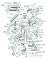
도 1은 본 발명에 따른 체력단련을 겸한 의자를 나타낸 사시도 이다.
도 2는 본 발명에 따른 체력단련을 겸한 의자의 저면을 나타낸 사시도 이다.
도 3은 본 발명에 따른 체력단련을 겸한 의자의 일부작동예상 측면도 이다.
도 4는 본 발명에 따른 체력단련을 겸한 의자의 주요부분 작동상태를 예시한 측면 사시도 이다.
도 5는 본 발명에 따른 체력단련을 겸한 의자의 각 부분을 분리하여 나타낸 사시도 이다.
도 6은 본 발명에 따른 체력단련을 겸한 의자의 주요부분 분리 및 절개하여 나타낸 사시도 이다.
도 7은 본 발명에 따른 체력단련을 겸한 의자의 팔걸이수단을 절개 및 분리하여 나타낸 사시도 이다.
도 8은 본 발명에 따른 체력단련을 겸한 의자의 등받이수단을 일부절개 및 분리하여 나타낸 사시도 이다.
도 9는 본 발명에 따른 체력단련을 겸한 의자의 완력수단을 분리 및 절개하여 나타낸 사시도 이다.
도도 10은 본 발명에 따른 체력단련을 겸한 의자의 등받이수단을 분리 및 절개하여 나타낸 사시도 이다.
도 11은 본 발명에 따른 체력단련을 겸한 의자의 발전수단을 분리하여 나타낸 분리사시도 이다.
도 12의 [A]는 본 발명에 따른 체력단련을 겸한 의자의 주요부분인 슬라이드봉의 작동상태를 나타낸 사시도 이다.
도 12의 [B]는 본 발명에 따른 체력단련을 겸한 의자의 주요부분인 슬라이드봉의 결합상태를 나타낸 사시도 이다.
도 13의 [A]는 본 발명에 따른 체력단련을 겸한 의자의 주요부분인 슬라이드봉의 삽입상태를 나타낸 사시도 이다.
도 13의 [B]는 본 발명에 따른 체력단련을 겸한 의자의 주요부인 슬라이드봉과 발걸이회전대의 결합직전의 상태를 나타낸 사시도 이다.
도 13의 [C]는 본 발명에 따른 체력단련을 겸한 의자의 주요부분인 슬라이드봉과 발걸이회전대가 결합된 상태를 나타낸 사시도 이다.
도 14의 [A]는 본 발명에 따른 체력단련을 겸한 의자의 주요부분인 코일스프링이 장착된 밀기부를 나타낸 사시도 이다.
도 14의 [B]는 본 발명에 따른 체력단련을 겸한 의자의 주요부분인 전, 후횡지지대 사이에 코일스프링이 장착한 상태를 나타낸 사시도 이다.
도 14의 [C]는 본 발명에 따른 체력단련을 겸한 의자의 주요부분인 코일스프링이 압축된 상태를 나타낸 사시도 이다.
도 14의 [D]는 본 발명에 따른 체력단련을 겸한 의자의 주요부분인 전, 후횡지지대에 장착된 코일스프링의 압축상태를 나타낸 사시도 이다.
도 15의 (A)는 본 발명에 따른 체력단련을 겸한 의자에 형성된 발전수단의 작동상태 예시하여 나타낸 예시도 이다.
도 15의 (B)는 본 발명에 따른 체력단련을 겸한 의자에서 목과 허리 척추의 연골을 이완시키는 동작을 예시하여 나타낸 예시도 이다.
도 15의 (C)는 본 발명에 따른 체력단련을 겸한 의자에서 아령과 역도를 하듯이 팔 들어올리는 운동과 아울러 발걸이를 올리고 내리면서 종아리 및 허벅지 근력 강화운동을 하는 것을 예시하여 나타낸 예시도 이다.
도 16의 (D)는 본 발명에 따른 체력단련을 겸한 의자에서 허벅지 근육강화운동을 하기 위해 발걸이에 발바닥을 대고 있는 것을 예시하여 나타낸 예시도 이다.
도 16의 (E)는 본 발명에 따른 체력단련을 겸한 의자에서 발걸이를 발로 밀어 스프링에 대응하는 왕복운동을 통해 허벅지 강화운동을 하는 것을 예시하여 나타낸 예시도 이다.
도 17의 (F)는 본 발명에 따른 체력단련을 겸한 의자에서 물구나무서기의 자세를 취하는 운동을 예시하여 나타낸 예시도 이다.
도 17의 [G]는 본 발명에 따른 체력단련을 겸한 의자에서 등받이를 수평이 되게 눕히고 발걸이에 발등을 걸어 허리를 앞으로 구부렸다가 뒤로 젖히는 복근강화 운동을 하는 것을 예시하여 나타낸 예시도 이다.1 is a perspective view showing a chair that also combines physical fitness according to the present invention.
Figure 2 is a perspective view showing the bottom of the chair combined with fitness training according to the present invention.
Figure 3 is a side view of the expected operation of some of the chair combined with physical fitness according to the present invention.
Figure 4 is a side perspective view illustrating the main part operating state of the chair combined with fitness training according to the present invention.
Figure 5 is a perspective view showing the separate parts of the chair also serves as fitness training in accordance with the present invention.
Figure 6 is a perspective view showing the separation and incision of the main part of the chair combined with strength training according to the present invention.
Figure 7 is a perspective view showing the cutting and separating the armrest means of the chair combined with physical training according to the present invention.
Figure 8 is a perspective view showing a partially cut and separated the back support means of the chair combined with physical fitness according to the present invention.
Figure 9 is a perspective view showing the separation and dissection of the reinforcement means of the chair combined with physical fitness according to the present invention.
Figure 10 is a perspective view showing the separation and dissection of the back support means of the chair combined with physical fitness according to the present invention.
Figure 11 is an exploded perspective view showing the separation of the power generating means of the chair combined with physical training according to the present invention.
[A] of Figure 12 is a perspective view showing the operating state of the slide bar which is the main part of the chair combined with the strength training according to the present invention.
[B] of FIG. 12 is a perspective view showing a coupling state of a slide bar which is a main part of a chair that also serves as a fitness exercise according to the present invention.
[A] of Figure 13 is a perspective view showing the insertion state of the slide bar which is the main part of the chair also serves as fitness training according to the present invention.
[B] of Figure 13 is a perspective view showing a state just before the combination of the slide bar and the foot swivel, which is the main part of the chair combined with the strength training according to the present invention.
[C] of Figure 13 is a perspective view showing a state in which the slide bar and the foot swivel coupled to the main part of the chair also serves as a fitness training according to the present invention.
[A] of Figure 14 is a perspective view showing a pusher mounted with a coil spring, which is the main part of the chair also serves as a fitness training according to the present invention.
[B] of FIG. 14 is a perspective view showing a state in which a coil spring is mounted between the front and rear lateral supports, which is a main part of the chair which also serves the fitness training according to the present invention.
[C] of Figure 14 is a perspective view showing a state in which the coil spring, which is the main part of the chair also serves as fitness training according to the present invention.
[D] of Figure 14 is a perspective view showing the compression state of the coil spring mounted on the front and rear lateral support, which is the main part of the chair combined with the strength training according to the present invention.
Figure 15 (A) is an exemplary view showing an example of the operating state of the power generation means formed on the chair also serves as a strength training according to the present invention.
Figure 15 (B) is an exemplary view showing an example of the operation to relax the cartilage of the neck and lumbar spine in the chair combined with the strength training according to the present invention.
Figure 15 (C) is an exemplary view showing an example of strengthening the calf and thigh muscle strengthening exercise while lifting and lowering the foot as well as lifting weights and lifting weights in the chair combined with fitness training according to the present invention.
Figure 16 (D) is an exemplary view showing that the sole is placed on the foot for the thigh muscle strengthening exercise in the chair combined with strength training according to the present invention.
Figure 16 (E) is an exemplary view showing an example of the thigh strengthening exercise through the reciprocating motion corresponding to the spring by pushing the foot to the foot in the chair combined with fitness training according to the present invention.
Figure 17 (F) is an exemplary view showing an example of the exercise taking the posture clerk standing in the chair also serves as fitness training according to the present invention.
[G] of FIG. 17 is an exemplary view illustrating an example of an abdominal muscle strengthening exercise in which the back of the back is horizontally laid in the chair which serves as the fitness training according to the present invention, the foot is inclined to the footrest, and the back is bent forward.
이하 본 발명에 따른 체력단련을 겸한 의자에 대한 바람직한 실시 예를 첨부된 도면을 참조하여 상세히 설명하고, 본 발명을 설명함에 있어 관련된 공지기술 등에 대하여는 본 발명의 요지를 흐리게 할 수 있다고 판단될 경우 그에 관한 자세한 설명은 생략하기로 한다.DETAILED DESCRIPTION OF THE PREFERRED EMBODIMENT Hereinafter, preferred embodiments of a chair having a physical fitness according to the present invention will be described in detail with reference to the accompanying drawings. Detailed description thereof will be omitted.
본 발명에 따른 체력단련을 겸한 의자의 주요 구성은 좌대수단(100)과, 완력수단(200)과, 팔걸이수단(300)과, 발걸이수단(400)과, 등받이수단(500)과, 발전수단(600)으로 이루어진다.The main configuration of the chair combined with the strength training according to the present invention is the seating means 100, the
상기 좌대수단(100)의 좌우에 형성된 지지기둥관(110), (110')의 삽입공간(110a)에는 팔걸이수단(300)이 결합되고, 상기 좌대수단(100)을 형성하는 제1관(112) 후방의 각도변환장치(122)에는 등받이수단(500)의 기어(122a)가 결합되고, 상기 제1관(112)의 삽입공간(112a)에는 발걸이수단(400)이 결합되고, 상기 좌대수단(100)의 좌, 우프레임(101), (101') 양측에는 완력수단(200)이 결합되고, 상기 좌대수단(100)의 좌, 우프레임(101), (101') 후방 하측 장홈프레임(106), (106')에는 발전수단(600)을 결합하여 구성한다. Arm first means (300) is coupled to the insertion space (110a) of the support columns (110, 110 ') formed on the left and right of the seat means 100, the first pipe (100) to form the seat means (100) 112, the
삭제delete
1) 좌대수단(100)의 구성1) Configuration of the seating means 100
상기 본 발명의 체력단련을 겸한 의자는 평상시 사람이 걸터앉는 의자로서, 상기 좌대수단(100)은 도 6에 도시한 바와 같이 후방 상측에 회전대장착공(101a")이 형성된 좌, 우프레임(101), (101')과 보강대(103), (103') 사이의 전, 후방에 전횡지지대(120)와 후횡지지대(121) 및 전, 후횡보강대(120'), (121')를 접합하여 틀을 구성하고,The chair that combines the physical strength of the present invention is a chair that a person usually sits on, and the seat means 100 has a
상기 전, 후횡지지대(120), (121)의 중앙부 양측에는 각각 통공(120a), (121a)을 형성하여 밀기부(140)의 슬라이드봉(141), (141')이 슬라이드 장착되도록 형성하고,Through
상기 전, 후횡지지대(120), (121)의 통공(120a), (121a)에 삽입되어 슬라이드 작동하는 밀기부(140)를 장착하기 위하여, 우선 다수의 가이드봉(143) 일측과 결합된 고정구(142)를 도 14에 도시한 바와 같이, 전횡지지대(120)의 통공(120a) 후면에 고정하고 가이드봉(143)의 타단부를 후횡지지대(121)의 통공(121a) 후방 외측에 고정하여 구성한다.In order to mount the pushing
상기 밀기부(140)의 슬라이드봉(141), (141')의 전방에는 발걸이회전대(420)에 형성된 결합구장착공(421a")과 결합할 수 있도록 ㄹ 자형의 결합구(141b), (141b')가 형성되어 있고, 슬라이드봉(141), (141')의 후단부에는 고정턱(141a)을 형성하여 코일스프링(145)을 압축할 수 있도록 구성한다.In front of the
즉, 발걸이회전대(420)에 형성된 결합구장착공(421a")으로 슬라이드봉(141), (141')에 형성된 결합구(141b), (141b')가 삽입고정되어 등받이(511)에 등을 기대고 발지압부재장착구(454)를 발로 밀며 전진함에 따라 코일스프링(145)의 미는 힘에 대응하는 압축작용을 발생시켜 이를 반복함에 따라 종아리와 허벅지 및 무릎관절의 근육을 강화할 수 있게 할 수 있는 것이다.That is, the coupling holes 141b, 141b 'formed in the
이러한 작용은 전횡지지대(120)의 통공(120a)과 후횡지지대(121)의 통공(121a) 사이에 장착되는 코일스프링(145)의 전후방 양단부에 고정구(142)와 와셔(145')를 형성하여 전횡지지대(120)의 통공(120a) 후면에 고정구(142)를 고정하고, 와셔(145')에 형성된 상, 하의 가이드공(145a')에 가이드봉(143)을 삽입하여 상, 하측 전방 단부를 고정구(142)의 상하에 결합하고 타단부는 후횡지지대(121)의 후방에 고정하면 슬라이드봉(141)이 전방으로 전진하면서 고정턱(141a)이 와셔(145')를 밀어 코일스프링(145)을 압축하기 때문이다.This action forms a
상기와 같이 전, 후횡지지대(120), (121)의 통공(120a), (121a)에 삽입되어 슬라이드 되도록 형성된 슬라이드봉(141), (141')의 전방에 형성된 결합구(141b), (141b')를 발걸이회전대(420)에 형성된 결합구장착공(421a")에 장착하여 전방으로 슬라이드 전진이 가능하게 구성하여, 슬라이드봉(141), (141')이 전진함에 따라 고정턱(141a)은 와셔(145')를 밀며 코일스프링(145)을 압축하도록 구성하는 것이다.As described above, the coupling holes 141b and (141b) formed at the front of the
그리고 상기 전, 후횡지지대(120), (121)의 하부면에 접합한 전, 후횡보강대(120'), (121')의 저면 중앙에는 슬라이드홈(113')을 형성한 안장대장착구(113)를 접합하여 안장지지대(641)가 장착된다.And the saddle mounting bracket formed with a
또한, 상기 전. 후횡지지대(120), (121)와 결합된 좌, 우프레임(101), (101')의 후방 하측에는 장홈(106a)이 형성된 장홈프레임(106)을 형성하여 후술하는 슬라이드대(615)에 접합된 돌쩌귀(615a)에 발전수단(600)을 장착한 장착프레임(610)의 일측이 장착되고,Also, the above. On the rear lower side of the left,
상기 좌, 우프레임(101), (101')에 형성된 회전대장착공(101a")으로는 우측에 잠금부(88)를 장착한 회전지지대(131), (131')의 회전축(131a), (131a')을 삽입하여 회전 가능하게 구성하고,Rotating shaft mounting holes (101a ") formed in the left, right frame (101), (101 '), the rotating shaft (131a) of the rotary support (131), (131') mounted with the locking
상기 회전지지대(131), (131')의 중앙에는 좌판지지대(132), (132')와 좌측면에 걸림구(112')가 접합된 제1관(112)을 형성하여 상단부에 사람이 앉을 수 있는 좌판(130)을 고정하여 구성하고,In the center of the
상기 제1관(112)의 전방 우측면에는 스프링(88a')을 장착한 잠금봉(88")을 장착하여 후술하는 발걸이수단(400)의 결합대(411)를 다리길이에 따라 고정하도록 구성한다.The front right surface of the
또한, 전횡지지대(120)의 상측에 체결부(99)를 장착하여 손잡이(99')로 회전하는 작동 여부에 따라 스프링(99a)에 의해 회전지지대(131), (131')를 고정하거나 해지하도록 구성한다.In addition, the
상기 제1관(112)에는 삽입공간(112a)을 형성하여 전술한 발걸이수단(400)의 발걸이회전대(420)가 탄성스프링(432), (432')을 장착하여 볼트(433)를 축으로 연장 결합된 결합대(411)가 삽입장착되도록 형성하고,The
상기 회전지지대(131), (131')와 접합된 제1관(112) 후방 단부에는 각도변환장치(122)를 장착한 후, 등받이수단(500)의 등판지지관(510) 하단부에 형성된 기어(122a)를 각도변환장치(122)에 결합하여 회전에 의해 고정되도록 형성한다. Gears formed at the lower end of the back
그리고 상기 제1관(112)의 후방 하측 저면에는 등받이수단(500)이 후방으로 수평 회전할 때 등판지지관(510)이 더 이상의 회전이 불가능하도록 정지턱(104)이 돌출되어 있다.The
또한, 좌, 우프레임(101), (101')의 중앙 양 측면에는 상측에 잠금부(88)를 장착하여 내부에 삽입공간(101a), (101a')을 형성된 지지기둥관(110), (110')을 수직으로 접합하고,In addition, the left and
상기 지지기둥관(110), (110')의 삽입공간(101a), (101a')에는 후술하는 팔걸이수단(300)의 높낮이조절공(310a)이 다수 천공된 높낮이조절대(310)를 삽입하여 키 높이에 따라 잠금부(88)의 손잡이(88')를 회전하여 잠금봉(88")으로 하여금 고정과 해지가 가능하도록 형성하고,Inserting the height adjustment table 310 is a plurality of
상기 좌, 우프레임(101), (101')의 양측에는 후술하는 완력수단(200)을 장착하여 완력손잡이(280)를 이용한 아령이나 역도 같은 운동을 할 수 있도록 구성한다.Both sides of the left and
또한, 상기 전, 후횡지지대(120), (121)의 통공(120a), (121a)에 슬라이드 장착되는 밀기부(140)에는 슬라이드봉(141), (141')의 전방 단부를 도 13의 [B], [C]와 도 14의 [A]에 나타내는 바와 같이 ㄹ 자형의 결합구(141b), (141b')를 형성하여 발걸이회전대(420)에 형성된 결합구장착공(421a")으로 삽입하여 고정할 수 있도록 구성하고,In addition, the front end of the
상기 전, 후횡지지대(120), (121)의 통공(120a) (121a)에 슬라이드 장착되는 슬라이드봉(141), (141')의 후단부에는 도 13의 [A]에 도시한 바와 같이 고정턱(141a)을 형성하여 슬라이드봉(141), (141')이 전진할 때 와셔(145')를 밀어 코일스프링(145)을 압축하도록 구성한다.Fixed to the rear ends of the
또한, 안장대장착구(113)의 상측에 배터리(665)를 후술하는 발전수단(600)의 발전기(651)와 전선(664)으로 연결하여 회전체(620)를 회전함에 따라 생산되는 전기를 베터리(665)에 충전 할 수 있도록 형성한다.In addition, the electric power produced by rotating the
그리고 좌, 우프레임(101), (101')의 전방 하부측에는 이동을 자제하도록 캡(160)을 장착하고, 후방 하단부에는 이동이 용이하도록 바퀴(140')를 결합하여 사람이 앉을 수 있는 좌대수단(100)을 구성한다.The left and
2) 팔걸이수단(300)의 구성2) configuration of the armrest means (300)
상기 팔걸이수단(300)의 구성은 도 7에 도시한 바와 같이 삽입공간(320a)을 형성한 팔걸이관(320)의 전방 단부에는 손지압부(330)를 장착하고,As shown in FIG. 7, the arm rest means 300 includes a
상기 팔걸이관(320)의 저면 중앙에는 다수의 높낮이조절공(310a)이 형성된 높낮이조절대(310)의 상단부를 접합하여 전술한 지지기둥관(110), (110')의 삽입공간(110a), (110a')에 슬라이드 삽입한다.In the center of the bottom surface of the
상기 팔걸이관(320)의 전방에는 공간(323)을 형성하여 양측 단부에 돌기삽입공(321)이 형성되고, 중앙에는 볼트삽입공(324)을 천공하여 탄성스프링(334)을 장착한 결합볼트(335)를 볼트삽입공(324)을 통해 손지압부재장착구(331)의 볼트장착너트(333)에 나사 결합하여 구성한다.The front of the
즉 상기 공간(323)에는 탄성스프링(334)을 삽입장착한 결합볼트(335)가 볼트삽입공(324)을 통해 볼트장착너트(333)에 나사 결합되어 있으므로 손지압부재장착구(331)를 잡고 전, 후방으로 전, 후진함에 따라 볼트삽입공(324)에서 슬라이드 이동과 동시에 탄성스프링(334)은 결합볼트(335)의 해드(335')와 공간벽(324')에 의해 탄지 및 탄발 하게 된다.That is, since the
상기 손지압부재장착구(331)에는 후방 양측에 돌기(331a)와 중앙으로 볼트장착너트(333)가 형성되며 전, 후방에 슬라이드홈(336), (336')이 형성되어 있다.The finger-pressure
상기 손지압부재장착구(331)에 형성된 슬라이드홈(336), (336')에는 손지압부재(338)를 장착하여 손을 지압할 수 있으며 탈부착이 가능하다.The slide grooves 336 and 336 ′ formed in the finger pressure
상기 손지압부재장착구(331)의 후방 좌우에는 돌기(332)를 형성하여 팔걸이관(320)의 공간(323) 단부에 형성된 좌우의 돌기삽입공(321)에 삽입되도록 형성한다.Protruding
그리고 상기 탄성스프링(334)을 장착한 결합볼트(335)는 팔걸이관(320) 전방 단부의 볼트삽입공(324)을 통해 손지압부재장착구(331)에 형성된 볼트장착너트(333)에 나사결합 되고 다수의 돌기를 형성한 손지압부재(338)는 상, 하에 형성된 슬라이드홈(336), (336')에 삽입장착되어 손지압부재장착구(331)의 하부에 고정되는 것이다.The
그리하여 손지압부(330)를 전방으로 잡아당겼다가 180도 회전하여 놓아주면 결합볼트(335)는 탄성스프링(334)에 의해 탄지 및 탄발되어 손지압부재장착구(331)와 더불어 손지압부재(338)의 위치가 바뀌어 고정되도록 구성한다.Thus, when the
이것은 손지압부재장착구(331)의 돌기(332)는 팔걸이관(320)의 전방에 형성된 공간(323)의 돌기삽입공(332a)에 삽입되어 있는 고로 손지압부재장차구(331)를 당길 경우 볼트장착너트(333)와 연장결합된 결합볼트(335) 만이 돌기삽입공(321)을 슬라이드 하면서 전진하게 되므로 탄성스프링(334)이 압축된 상태에서 회전할 수 있기 때문이다.This is the
그리고 상기 팔걸이관(320)에 결합된 손지압부(330)를 전방으로 잡아당겨 주게 되면 손지압부재장착구(331)는 팔걸이관(320)에서 전방으로 이동하여 분리된다. 이때 팔걸이관(320)의 볼트삽입공(324)과 너트(333)에 나사결합된 결합볼트(335)는 공간벽으로 인해 탄성스프링(334)은 의해 압축된다.Then, when the hand
이렇게 하여 즉시 손지압부재장착구(331)를 180도 회전한 후 놓아주게 되면 압축 상태의 탄성스프링(334)이 탄발되면서 손지압부(330)를 후방으로 잡아 당겨주게 되므로 손지압부(330)에 형성된 손지압부재(338)는 하부측을 향해 형성되어 있다가 손지압부재장착구(331)와 더불어 회전하여 상부측에 위치됨과 동시에 결합볼트(335)에 삽입된 탄성스프링(334)이 탄발하면서 돌기(332)가 돌기삽입공(321)에 삽입되어 고정되는 것이다.In this way, immediately after the hand pressure
이것은 팔걸이관(320) 단부의 볼트삽입공(324)에서 손지압부재장착구(331)의 너트(333)에 탄성스프링(334)이 삽입된 결합볼트(335)의 해드(335')가 팔걸이관(320)의 공간(323)에서 이탈할 수 없게 돌출되어 있는 고로 손지압부재장착구(331)에 형성된 돌기(332)가 180도 회전함에 따라 돌기(332)의 위치도 180도 이동되기 때문이다.The head 335 'of the
따라서 손지압부(330)를 이용하여 손을 지압을 한 다음, 사용하지 않을 때에는 전술한 바와 같이 손지압부(330)를 전방으로 당겨 180도 회전시킨 후 놓아주게 되면 손지압부(330)에 형성된 돌기(332)는 위치가 바뀌어 고정되는 것이다.Therefore, after pressing the hand using the
그리고 상측에 잠금부(88)를 장착한 지지기둥체(110)의 삽입공간(110a)에 삽입된 높낮이조절대(310)를 상측으로 이동하여 원하는 길이만큼 높이를 조절하여 잠금부(88)로 하여금 높낮이조절공(310a)에 고정하면 팔걸이관(320)의 높낮이를 선택하여 고정할 수 있게 하는 것이다.Then, by moving the
이렇게 구성된 팔걸이관(320)에 팔꿈치나 겨드랑이를 걸고, 체중을 실어주어 엉덩이가 좌판(130)에서 약간 들린 상태를 유지하여 엉덩이를 좌우로 흔들거나, 어깨를 상하로 올렸다가 내리는 동작을 하게 되면 척추의 연골이 이완되므로 허리 척추 사이 사이의 연골이 하중으로 인해 강화되어 추간판탈출증 같은 허리디스크를 예방 및 치료를 할 수 있게 되는 것이다.The armrest tube (320) configured in this way to hang the elbows or armpits, giving weight to keep the hips slightly lifted from the
3) 등받이수단(500)의 구성3) Configuration of the backrest means 500
상기 등받이수단(500)의 구성은 도 10에 나타내는 바와 같이, 양측 등판보강대(510')의 중앙에는 등판지지관(510)을 접합하여 등을 기댈 수 있도록 전면에 등받이(511)를 고정하고,As shown in FIG. 10, the structure of the
상기 등판지지관(510)에는 삽입공간(510a)을 형성하여 다수의 높낮이조절공(520a)을 형성한 지지봉(520)이 수직으로 삽입되도록 구성한다.The
그리고 상기 등판지지관(510)의 하단부에는 기어(122a)를 고정하여 회전지지대(131), (131')의 후방에 접합된 각도변환장치(122)와 결합하여 등판지지관(510)을 앞으로 회전하였다가 뒤로 회전함에 따라 고정이 풀려 각도가 조절되고, 다시 각도 변환할 때는 등받이(511)를 한 번 더 앞으로 젖혀서 고정을 푼 다음, 회전하는 도중에 원하는 각도에서 고정할 수 있도록 구성한다.In addition, the
또한, 상기 회전지지대(131), (131')의 중앙에 접합된 제1관(112)의 후방에는 등판지지관(510)이 더 이상의 회전을 중지하고 멈출 수 있게 정지턱(104)을 돌출하여 좌판(130)에 앉아 허리굽혀펴기운동을 하거나 물구나무서기 운동을 하기 위해 등받이(511)를 수평이 되게 회전하여도 제1관(112)의 후방에 돌출된 정지턱(104)으로 인해 더 이상의 회전이 불가능하도록 구성한다.In addition, the
상기 각도변환장치(122)는 일반적으로 알려진 구성으로 상세한 구성은 생략한다.The
상기 등판지지관(510)의 상측에는 다수의 높낮이조절공(520a)이 형성된 지지봉(520)의 높낮이를 조절할 수 있도록 잠금부(88)를 장착되어 있다.The upper side of the
그리고 상기 지지봉(520) 상측에 형성된 목단련부(530)에는 좌우에 돌쩌귀(522), (522')가 형성된 결합체(521)를 접합하여 후방에 자석(532a)을 결합한 턱걸이(532), (532')를 축(532a")으로 장착하여 수평회전이 가능하게 하고,And to the
상기 결합체(521)의 중앙부 상, 하에는 돌쩌귀(523), (523')를 볼트(55)로 장착하여 다수의 돌기를 형성한 목지압부재(531)를 축(531a)으로 결합하여 구성한다.Above and below the central portion of the
상기 턱걸이(532), (532')에는 결합체(521)의 돌쩌귀(522), (522')와 결합하도록 한 후 단부에 돌출구(522a")가 형성되고, 타측의 턱걸이(532')에도 후단부에 돌출구(522a")를 형성하여 결합체(521)의 돌쩌귀(522), (522')와 축(532a")으로 결합되도록 형성되어 있다.The
상기 지지봉(520)의 상측에서 턱을 지지하도록 형성된 턱걸이(532), (532')는 도 10에 도시한 바와 같이 한 쌍으로 이루어지며, 결합체(521)의 양측 돌쩌귀(522), (522')에 각각 축(532a")으로 장착되어 수평회전하도록 형성되어 있다.Chin hooks 532, 532 'formed to support the jaw on the upper side of the
그리고 상기 결합체(521)의 중앙부 상하에 축(531a)으로 장착되는 목단련부(530)에는 다수의 지압용 돌기가 형성된 목지압부재(531)를 장착하여 상체를 좌우로 움직이면서 양 어깨 사이의 목 뒷부분에 지압이 가해지도록 형성하고,And the
상기 결합체(521)의 좌우측 턱걸이(532), (532')에는 턱을 걸고 목 척추의 연골을 이완시켜 경추 척추증 같은 목디스크를 예방하거나 치료할 수 있게 형성한다.The left and right jawrests 532 and 532 'of the
또한, 상술한 턱걸이(532), (532')는 축(532a")에 의해 양손으로 벌리거나 오므릴 수 있는 것으로, 사용하지 않을 경우 후방으로 회전하여 결합체(521)의 돌쩌귀(522), (522')측에 형성된 자석(532a)의 자력에 의해 접지되어 고정되도록 형성한다.In addition, the above-described
그리고 등판지지관(510) 상측에 장착된 잠금부(88)의 손잡이(88')를 이용하여 삽입공간(510a)에 삽입된 지지봉(520)의 높낮이조절공(520a)을 선택한 후 손잡이(88')와 연장결합된 잠금봉(88")으로 하여금 높낮이 조절이 가능하도록 형성한다.Then, using the handle 88 'of the locking
따라서 지지봉(520)을 일정길이 키 높이에 따라 상승한 후 잠금부(88)로 고정하여 턱걸이(522), (522')에 턱을 걸고 체중을 싣게 되면 목의 척추가 이완되므로 이로 인해 경추 척추증 같은 목디스크를 예방 및 치료할 수 있는 것이다.Therefore, after raising the
4) 완력수단의 구성4) Composition of force means
상기 완력수단(200)의 구성은 도 9에 도시한 바와 같이 캡(220)과 하우징(210) 내부에 판스프링(240)과 와이어로프(270)가 장착되어 형성되고,9, the
상기 하우징(210)은 좌, 우프레임(101), (101')과 보강대(103)의 측면에 나사로 결합하여 고정된다.The
이때 하우징(210)의 내부에는 원형돌기(211)가 형성되어 있고 원형돌기(211) 내부에는 고정볼트결합공(212)이 형성되어 있다.In this case, a
상기 원형돌기(211)의 외주면으로 삽입하는 원형돌출구(251)는 스프링압축회전체(250)의 중앙부에 돌출되어 중앙에 관통공(255)를 형성한다.The
그리고 원형돌출구(251)의 외주면에 고정걸이구(252)를 형성하여 판스프링(240)의 일측이 고정되도록 형성한다.In addition, the fixing
이때 원형돌출구(251) 외주면으로 삽입되는 캡(220)의 중앙 일측 부분에는 고정걸이구(252)를 경유하여 스프링압축회전체(250)의 내측에 삽입될 때 걸리지 않도록 고정걸이구삽입홈(221)을 형성한다.At this time, the central one side portion of the
따라서 상기 원형돌출구(251)에 먼저 캡(220)을 삽입한다.Therefore, the
이때 원형돌출구(251)의 고정걸이구(231)는 캡(220)의 고정걸이구삽입홈(221)을 통해 삽입되어 스프링압축회전체(250)의 내측에 위치되도록 한다.At this time, the fixing
상기 원형돌출구(251)의 고정걸이구(252)에 판스프링(240)의 일측을 고정하고, 타측은 회전체(230)에 천공된 스프링장착홈(231)에 삽입하여 삽입방향 반대로 판스프링(240)의 단부를 접어 고정하고 와이어로프(270)의 일측을 회전체(230)에 고정한다.One side of the
상기 판스프링(240)이 장착된 회전체(230)에 와이어로프(270)의 일측을 휘감아 고정한 다음, 타측을 하우징(210)의 출입공(210a)을 통해 외부로 인출한 후 완력손잡이(280)에 고정한다.One side of the
상기 원형돌출구(251)를 형성하여 중앙이 관통된 스프링압축회전체(250)를 하우징(210)에 형성된 원형돌기(211)의 외주면에 삽입한 다음, 스프링압축회전체(250)의 중앙에 관통된 관통공(255)을 통해 고정볼트(323)를 이용하여 원형돌기(211)의 고정볼트결합공(212)에 나사식으로 고정하여 결합하면 스프링압축회전체(250)는 원형돌기(211)의 외주면을 중심으로 회전함으로 이탈하지 않고, 손잡이(260)를 회전함에 따라 판스프링(240)은 원하는 만큼의 탄력성을 누적하게 된다.The
또한, 상기 스프링압축회전체(250)의 일측에는 돌쩌귀(250a)와 요홈(253')을 형성하여 일측에 손잡이(260)를 장착한 손잡이결합대(265)의 타측을 상술한 돌쩌귀(250a)에 축(265a)으로 결합하여 회전 가능하게 형성하여 손잡이(260)를 회전함에 따라 회전체(230)를 회전시켜 일정강도 판스프링(240)을 압축한 다음, 하우징(210)에 형성된 손잡이걸림홈(254)으로 손잡이(260)를 회전하여 삽입고정되도록 구성한다.In addition, the one side of the spring
이렇게 하면 상기 하우징(210) 외주변의 손잡이걸림홈(254)으로 손잡이(260)를 회전하여 고정하는 과정에서 손잡이결합대(265)도 따라서 요홈(253')에 삽입된다.In this way, the handle engaging table 265 is also inserted into the groove 253 'in the process of rotating and fixing the
즉 상기 일측 돌쩌귀(250a)에는 손잡이(260)을 장착한 손잡이결합대(265)의 단부를 축(265a)으로 결합하여 회전가능하게 하고, 타측은 손잡이(260)를 회전하여 손잡이걸림홈(254)에 고정 시킬 때 동시에 삽입되는 것이다.That is, the one side (250a) is coupled to the end of the handle engaging table 265 equipped with the
이러한 작용은 하우징(210)이 좌, 우프레임(101), (101')에 고정되어 있는 고로, 원형돌기(211)의 외주면에서 고정볼트(323)의 의해 결합하여 손잡이(260)에 의해 회전하는 스프링압축회전체(250)는 압축된 판스프링(240)의 탄성을 유지하면서 하우징(210)에 형성된 출입공(210a) 외부에 버티고 있기 때문에 완력손잡이(280)를 당기게 되면 회전체(230)의 스프링장착홈(231)에 장착된 판스프링(240)이 회전함에 따라 더욱 압축되면서 탄성을 발휘하는 것이다. This action is because the
이렇게 구성된 스프링압축회전체(250)의 돌쩌귀(250a)에 축(265a)으로 결합된 손잡이결합대(265)의 손잡이(260)를 이용하여 정, 역회전함에 따라 회전체(230)의 스프링장착홈(231)과 원형돌출구(251)의 고정걸이구(252)에 양단부가 고정된 판스프링(240)의 탄성력을 강하게 하거나 느슨하게 하여 자신의 능력에 따라 조절한 다음, 손잡이(260)를 손잡이걸림홈(254)에 삽입고정하여 완력손잡이(280)를 손으로 잡고 아령 및 역기 같은 운동을 할 수 있는 것이다.Spring mounting of the
즉 아령 및 역기 운동하는 사람의 근력에 따라 손잡이(260)를 이용하여 판스프링(240)의 압축을 정 회전하거나 역회전으로 조절하여 손잡이걸림홈(254)에 고정한 후 완력손잡이(280)를 잡고 팔 들어올리는 아령 및 역기 같은 운동을 할 수 있게 되는 것이다.In other words, according to the strength of the dumbbell and the exercise of the exercise device by using the
이렇게 구성된 완력수단(200)은 완력손잡이(280)를 잡아당겼다 놓았다 함에 따라 판스프링(240)이 압축 및 해제되면서 회전체(230)를 회전시킨다. 따라서 판스프링(240)의 탄력에 의해 아령이나 역도를 들었다가 놓듯이 팔운동을 할 수 있는 것이다.The tension means 200 configured as described above pulls and releases the
상기와 같이 판스프링(240)의 탄력을 강화 및 완화하기 위해서 먼저, 스프링압축회전체(250)에 형성된 손잡이(260)를 손잡이걸림홈(254)에서 분리하여 180도 회전할 때, 손잡이대(265)는 손잡이걸림홈(254)과 요홈(253')에서 동시에 분리된다. 그리고 나서 손잡이(260)를 정 회전시키면 판스프링(240)이 압축되어 강해지므로 근력 운동을 강화시키고, 손잡이(260)를 역회전시키면 판스프링(240)이 풀어저 느슨하게 되므로, 근력 운동을 수요자의 취향에 따라 완력손잡이(280)를 잡고 팔의 근력 운동을 조절하여 운동을 할 수 있는 것이다.In order to reinforce and alleviate the elasticity of the
5) 발걸이수단(400)의 구성5) configuration of the footrest means (400)
상기 발걸이수단(400)의 구성은 도 8에 나타내는 바와 같이, 좌우 회전지지대(131), (131')와 좌판지지대(132), (132')의 중앙에 접합된 제1관(112)의 삽입공간(112a)으로 발걸이회전대(420)와 결합된 결합대(411)가 삽입장착되도록 구성된다.As shown in FIG. 8, the structure of the footrest means 400 includes the
상기 회전지지대(131), (131')와 좌우 좌판지지대(132), (132')의 중앙에 접합되어 삽입공간(112a)이 형성된 제1관(112)의 전방 좌, 우측에는 잠금부(88)와 ㄴ자형의 걸림구(112')를 각각 장착하고,Locking portions are formed at the front left and right sides of the
상기 제1관(112)에 장착된 잠금부(88)는 후술하는 발지압부재(453)에 발등을 걸고 다리굽혀펴기운동을 할 때 키높이(다리길이)에 따라 결합대(411)를 전방으로 슬라이드 전진하여 고정시킬 수 있게 하는 것이다.The locking
상기 제1관(112)에 접합된 걸림구(112')는 전술한 전횡지지대(120)의 상측에 장착된 체결부(99)의 작동 여부에 따라 고정 및 해지가 이루어지도록 형성된 것으로, 좌판(130)을 회전해야 할 경우 전횡지지대(120)의 상측에 장착되어 ㄴ 자형의 걸림구(112')와 결합된 체결부(99)의 손잡이(99')를 이용하여 걸림구(112')에서 체결구(99")를 해지한 후 회전대장착공(101a")을 중심으로 좌판(130)을 회전하도록 구성된다.The
상기 걸림구(112')는 체결부(99)의 체결구(99")와 결합하여 고정된 상태를 유지하고 있다가 물구나무서기 운동 등을 해야 할 경우 체결부(99)의 손잡이(99')를 이용하여 걸림구(112')에서 체결구(99")를 해지하여 발지압부재장착구(454)에 발등을 걸고 등받이(511)에 등을 기대며 체중을 싣게 되면 간단히 물구나무서기 운동을 할 수 있는 것이다.The latch 112 'is coupled to the
또한, 상기 제1관(112)에 삽입한 결합대(411)의 전방 좌, 우측에는 스프링장착공(411'),(411")과 발걸이회전대장착공(411a), (411a')을 형성하고,In addition,
상기 결합대(411)의 전방에 볼트(433), 너트(433')로 장착되는 발걸이회전대(420)에는 상부면 양측으로 결합구장착공(421a")과 스프링장착공(421)을 형성하고, 하측에는 다수의 높낮이조절공(420a)을 형성하여 결합대(411)의 양측 스프링장착공(411'), (411")에 탄성스프링(432), (432')의 일측을 각각 삽입하고, 타측은 발걸이회전대(420)의 스프링장착공(421), (421')에 각각 삽입한 다음, 양측 탄성스프링(432), (432')의 이탈방지를 위한 와셔(431), (431')를 위치한 다음, 볼트, 너트(433), (433')를 이용하여 발걸이회전대장착공(411a), (411a')과 결합대장착공(421a), (421a')을 통해 결합하면 발걸이회전대(420)의 발지압부(450)를 회전할 때 볼트(433)를 축으로 탄성스프링(432), (432')에 의해 힘이 대응하게 되어 일정각도의 회전과 복원작용을 하게 된다.On the
그리고 상기 발걸이회전대(420)에 삽입하여 높낮이를 정하여 고정할 수 있도록 형성된 발지압부(450)의 사각틀(451) 전방에는 잠금부(88)의 잠금봉(88")이 삽입되도록 통공(452a)을 형성한 사각틀(451)의 양측에 돌쩌귀(108)를 접합하고, 상기 돌쩌귀(108)와 잠금부(88)를 축(88a)으로 결합하여 손잡이(88')의 회전에 따라 잠금과 해지가 가능 도록 구성하고,The through
상기 사각틀(451)의 좌, 우에는 장착봉(452), (452')을 접합하여 다수의 돌기가 형성된 발지압부재(453)를 슬라이드홈(454a)에 장착한 발지압부재장착구(454)의 통공(454a')을 통해 삽입장착하여 상하에서 슬라이드 고정이 가능하도록 형성하고,The left and right sides of the
상기 사각틀(451)의 좌, 우에 접합된 장착봉(452), (453')에 삽입장착되는 발지압부재장착구(454)의 좌, 우측에는 찍찍이(440a')가 형성된 접착띠(441)와 걸고리(440)가 고정된 결합띠(440')를 장착하여 구성하고,
상기 발지압부재장착구(454)에 형성된 통공(454a')을 통해 각각 장착봉(452), (452')에 삽입장착하여 발지압부(450)를 구성한다.Through the
또한, 전, 후횡지지대(120), (121)의 통공(120a), (121a)에서 슬라이드 작동하는 밀기부(140)를 장착하기 위하여 우선 전횡지지대(120)의 통공(120a) 후면에 고정구(142)를 미리 장착하고, 따라서 후횡지지대(121)의 통공(121a)에 가이드봉(143)을 삽입하여 와셔(145')의 상, 하측 가이드공(145a')에 각각 가이드봉(143)을 장착한 다음, 가이드봉(143)의 단부에는 고정구(142)를 고정하고, C자형의 후단부는 후횡지지대(121) 통공(121a)의 후면 상하에 고정하면, 전, 후횡지지대(120), (121) 사이에서 가이드봉(143)에 장착된 상태로 와셔(145')가 위치하게 된다.In addition, in order to mount the pushing
또한, 전, 후횡지지대(120), (121)의 통공(120a), (121a)으로 ㄹ자형의 결합구(141b), (141b')를 형성한 슬라이드봉(141), (141')을 슬라이드 삽입하여 코일스프링(145), (145)을 장착한 후, 후횡지지대(121)의 통공(121a)을 통과하여 슬라이드봉(141), (141')의 후단부에 고정턱(141a)을 접합하면 코일스프링(145)은 전, 후횡지지대(120), (121) 사이에 위치하게 되어 결합구(141b), (141b')를 전방으로 당길 경우 고정턱(141a)이 와셔(145')를 밀어 코일스프링(145)을 압축하도록 하는 밀기부(140)를 구성한다.Also, the
그리고 도 13의 [B]와 [C]에 나타내는 바와 같이, 상기 슬라이드봉 전방에는 발걸이회전대(420)에 형성된 결합구장착공(421a")과 회전결합할 수 있도록 형성된 ㄹ 자형의 결합구(141b)를 결합구장착공(421a")에 삽입장착하고,And, as shown in [B] and [C] of FIG. 13, the front of the slide rod is a r-shaped
상기 발걸이회전대(420)의 높낮이조절공(420a) 하측에 장착된 발지압부(450)를 상향고정한 후, 좌판(130)에 앉아 등받이(511)에 등을 기대고 발지압부재장착구(454)에 발바닥을 위치하면 도 16의 [D]와 같이, 무릎이 ㄱ 자형으로 불편한 자세가 되는데 이때 발바닥으로 발지압부재장착구(454)를 전방으로 밀어주게 되면 도 16의 [E]와 같은 자세를 취하게 됨에 따라 동시에 고정턱(141a)이 와셔(145')를 전진시켜 코일스프링(145)을 압축하게 된다.After fixing the holding
즉, 발걸이회전대(420)에 형성된 결합구장착공(421a")에 슬라이드봉(141)의 결합구(141b)가 삽입고정된 관계로 등받이(511)에 등을 기대고 발지압부재장착구(454)를 발로 밀며 전진함에 따라 코일스프링(145)은 미는 힘에 대응하는 압축작용을 발생시켜 이를 반복 함으로써 종아리와 허벅지 및 무릎관절의 근력을 강화할 수 있게 된다.In other words, the coupler mounting hole (421a ") formed in the
상기와 같이 전, 후횡지지대(120), (121)의 통공(120a), (121a)에 장착된 밀기부(140)의 슬라이드봉(141), (141')이 통공(120a), (121a)으로 전, 후진하며 슬라이드 할 수 있도록, 슬라이드봉(141), (141') 전방의 결합구(141b), (141b')는 발걸이회전대(420)에 형성된 결합구장착공(421a")에 장착되어 있으므로 슬라이드 전, 후진이 가능하고 따라서 슬라이드봉(141), (141')이 전진함에 따라 고정턱(141a)은 코일스프링(145)을 압축하게 되는 것이다.As described above, the
이렇게 형성된 발걸이회전대(420)의 결합구장착공(421a")에 밀기부(140)의 결합구(141b)가 삽입장착되어 있는 고로, 발지압부(450)의 잠금부(88)를 손잡이(88')로 해제하여 상측 높낮이조절공(420a)에 상승고정함으로써, 등받이(511)에 등을 기대고, 발지압부재장착구(454)에 발바닥을 위치하면 무릎이 ㄱ 자형으로 접혀지는 불편한 자세가 되는 것이다.Thus, the engaging
이때 발바닥으로 발지압부재장착구(454)를 전방으로 수평되게 밀어주면, 밀기부(140)의 슬라이드봉(141) 후단부의 고정턱(141a)이 전방으로 전진하면서 와셔(145')를 밀어 코일스프링(145)을 압축하게 된다.At this time, when the foot pressure
그리고 발지압부재장착구(454)의 좌, 우 양측에는 찍찍이(440a')가 형성된 접착띠(441)와 결합띠(440')에 고정된 걸고리(440)를 각각 장착하여 발을 묶어 고정할 수 있도록 형성되어 있다.In addition, the left and right sides of the finger holding
또한, 상기 발지압부(450)에 형성된 사각틀(451)의 삽입공(450a)을 발걸이회전대(420)에 키 높이에 따라 삽입하여 높낮이조절공(420a)을 선택한 다음, 잠금부(88)로 하여금 높낮이조절공(420a)을 선택하여 고정하고, 좌판(130)에 앉아 발지압부재장착구(454)에 발등을 걸고 회전운동을 하게 될 때, 일측에 잠금부(88)를 장착한 제1관(112)의 삽입공간(112a)으로 삽입된 결합대(411)의 단부에는 발걸이회전대(420), 탄성스프링(432), (432'), 볼트(433), 너트(433') 등을 서로 결합하여 결합부(410)를 구성함으로써, 탄성스프링(432), (432')에 대응하는 복원운동을 할 수 있게 되는 것이다.In addition, the
상기와 같이 구성된 발걸이수단(400)의 발걸이회전대(420)를 사용하기 위해서는 먼저 제1관(112) 전방 측면에 결합된 잠금부(88)의 잠금상태를 해지하고, 발걸이회전대(420)를 전방으로 일정길이 키높이에 따라 인출하면 발걸이회전대(420)와 일체가 된 결합대(411)가 인출되는데, 이때 잠금부(88)로 고정하고 난 다음, 좌판(130)에 앉아 발지압부재장착구(454)에 발등을 걸고 다리에 힘을 가해 상측으로 상승 및 복원하기를 반복하여 제1관(112)에서 인출되어 잠금부(88)에 의해 고정된 결합대(411)와 연장 결합된 발걸이회전대(420)로 인해 탄성스프링(432), (432')이 탄성을 받게 되어 스프링의 힘에 대응하는 왕복운동으로 상승과 하강을 반복함에 따라 종아리 근육 및 허벅지 근육을 강화시키게 된다.In order to use the
따라서 상술한 운동방법은 복부에도 영향을 미치게 되며 종아리 및 허벅지 근육을 강화시킬 수 있게 한다.Therefore, the above-described exercise method also affects the abdomen and makes it possible to strengthen the calf and thigh muscles.
또한, 발걸이회전대(420)가 하강한 상태에서는 다수의 돌기가 형성된 발지압부재(454')에 발바닥 및 발가락을 지압할 수 있다.Further, in the state where the
그리고 상술한 바와 같이, 각도변환장치(122)와 결합된 기어(122a)는 등판지지관(510) 하단부에 고정되어 있어서 등판지지관(510)이 회전할 때 동시에 회전하게 형성되어 있음으로 등받이수단(500)을 후방으로 수평이 되게 회전하여 눕히고, 발지압부재장착구(454), (454)에 양발을 걸고 허리를 앞으로 구겼다가 뒤로 젖히는 복부근력 강화운동을 하거나, 전횡지지대(120)의 상측에 장착되어 제1관(122)에 접합된 걸림구(112')에 삽입고정된 체결부(99)의 손잡이(99')를 회전하여 걸림구(112')에 고정된 체결구(99")를 해지한 다음, 발지압부재장착구(454)에 발등을 걸고 좌판(130)과 등받이(511)에 상체의 체중을 실어 회전하여 물구나무서기를 할 수 있도록 구성하는 것이다.As described above, the
이때 상기 발지압부재장착구(454)의 일측에는 걸고리(440)를 장착한 결합띠(440')와 타측에 찍찍이(440a')를 형성한 접착띠(441)를 형성하여 안전하게 발을 감아 묶고 안전하게 물구나무서기를 할 수 있도록 구성하는 것이다.At this time, on one side of the holding
그리고 본 발명의 발지압부재(453)를 장시간 사용하다가 비위생적이 될 경우 발지압부재장착구(454)의 슬라이드홈(454a)에서 인출 다음, 세척하여 재사용 할 수 있다.In addition, when the
6) 발전수단(600)의 구성6) Configuration of the generating means 600
본 발명에 따른 상기 발전수단(600)의 구성은 도 11에 나타내는 바와 같이, 회전체(620)가 결합구(626)에 삽입되어 제어부(640)는 장착프레임(610), (610')에 결합되고, 가속저항부(630)는 연장프레임(611), (611')에 결합하여 구성하고,11, the
또한, 돌출대(626a)가 형성된 결합구(626)에 삽입장착되도록 회전체(620)의 중앙 결합공(620a) 양측에는 요홈(620a')을 형성하고, 상기 결합공(620a)과 요홈(620a')으로 결합구(626)를 삽입장착하여 구성한다.In addition,
또한, 외주면에 다수의 기어(620')를 형성한 회전체(620)는 결합공(620a)의 요홈(620a')에 결합구(626)의 돌출대(626a)가 서로 맞물려 결합구(626)로 인해 회전체(620)가 동시에 회전하도록 형성한다.In addition, in the
상기 단부에 걸림각(626a')과 너트(55)가 형성된 결합구(626)의 양단부에는 페달(624)을 장착한 페달대(625)의 걸림공(625a')을 삽입하여 볼트(55)로 고정하면 페달(624)을 회전함에 따라 결합구(626)와 회전체(620)가 회전함과 동시에 발전기(651)의 헤드(663)에 형성된 기어(662)가 회전하며 발전되도록 형성한다.The locking holes 625a 'of the pedal stand 625 on which the
상기 결합구(626)의 양단부에 각각 장착프레임(610), (610')의 통공(612a')을 삽입하여 볼트(55)로 고정한 다음 페달(624)을 회전하면 결합구(626)와 회전체(620)가 장착프레임(610), (610')의 통공(612a')을 중심으로 동시에 회전하게 된다.Inserting through
그리고 상기 장착프레임(610), (610')의 양측에는 하측에 통공(610a")을 형성한 보조대(610a)를 접합하여 상측 통공(611a')과 하측 장홈(611a)을 형성한 ㄱ 자형의 연장프레임(611), (611')과 축(610a')으로 결합하여 회전 가능하게 하고,And the both sides of the mounting frame (610, 610 ') the a-shaped to form the upper through hole (611a') and the lower long groove (611a) by joining the
상기 연장프레임(611), (611')의 하측에는 ㄷ 자형의 버팀프레임(613)을 접합하여 좌우의 페달(624)을 번갈아 밟으며 회전운동을 할 때 몸의 균형을 유지할 수 있도록 형성하고,The lower side of the
그리고 상술한 보조대(610a)와 접합된 장착프레임(610), (610')의 하단부 통공(612a)을 슬라이드대(615)에 접합한 돌쩌귀(615a)에 축(612)으로 결합하여 회전 가능하게 함으로써, 발전수단(600)을 이용하여 자전거타기운동을 할 때 180도 회전하여 버팀프레임(613)이 지면을 지지하게 하여 사용 가능하도록 형성한다.And the
상기에 슬라이드대(615)를 좌, 우프레임(101), (101')의 후방 하측에 접합된 장홈프레임(106)의 장홈(106a)에 삽입하여 슬라이드 이동이 가능하도록 형성한다.The slide table 615 is inserted into the
그리고 상기 슬라이드대(615)의 양단부에는 통공(616a)을 형성한 이탈방지턱(616)을 접합하고,And the end of the
상기 슬라이드대(615)에 형성된 이탈방지턱(616)의 통공(616a)에 조임볼트(50)를 삽입하여 장홈프레임(106)의 좌우에 형성된 너트(106b), (106b')를 선택하여 나사고정하여 슬라이드대(615)가 장홈(106a)에서 슬라이드 이동할 때 이탈하지 못하도록 한다.Insert the tightening
즉 장홈프레임(106), (106')의 장홈(106a), (106a')에서 슬라이드 이동이 가능하도록 이탈방지턱(616)과 접합된 슬라이드대(615)를 필요에 따라 전진이나, 후진을 한 후 장홈프레임(106), (106')의 전, 후방에 형성된 너트(106b), (106b')를 선택하여 조임볼트(50)로 고정할 수 있도록 하는 것이다.That is, the slide table 615 bonded to the
그리고 장착프레임(610), (610') 사이에 제어부하우징(653)을 형성한 장착홈(653a)에 다수의 발전기(651)를 삽입장착하고 발전기(651)의 해드(663)에 형성된 기어(662)와 회전체(620) 외주면의 기어(620')가 서로 맞물리게 형성하여 회전체(620)가 회전함에 따라 동시에 발전기(651)의 기어(662)를 회전시켜 전기를 생산할 수 있도록 형성한다.In addition, a plurality of
상기 발전기(651)와 배터리(665)에 전선(664)을 연결하여 회전체(620)가 회전할 때 발전기(651)의 해드(663)에 설치된 기어(662)는 회전체(620)의 기어(620')와 맞물린 관계로 동시에 회전하면서 전기를 생산하여 출력선(665")을 제어부(640)에 연결할 수 있도록 구성한다.When the
이렇게 돌쩌귀(615a)에 축(612)으로 결합된 장착프레임(610), (610')을 장착한 슬라이드대(615)는 전, 후진으로 이동함과 아울러 축(610a)에 결합되어 있어서 회전 가능하다.Thus, the slide table 615 equipped with the mounting
상기 장홈프레임(106), (106') 양측에 결합공(610a")이 형성된 보조대(610a)를 접합한 다음, 하측에 장홈(611a)이 형성된 연장프레임(611), (611')의 상단부 통공(611a')을 보조대(610a)의 결합공(610a")에 축(610a')으로 결합하여 회전 가능하게 하고. 연장프레임(611), (611')의 장홈(611a)에는 롤러프레임(633)에 저항롤러(631')를 장착한 밀림축(631a)을 삽입하고,After joining the
상기 양측 연장프레임(611), (611') 하부와 버팀프레임(613) 상단 중앙부에 너트(614a)가 형성된 버팀판(614)을 접합하여 가속조절구(630a)를 너트(614a)에 나사 삽입하면 롤러프레임(633)에 형성된 돌출홈(632)의 홈(632a)에 위치하게 되어 가속조절구(630a)를 정회전과 역회전함에 따라 회전체(620)의 외주면을 압박하거나 압박하지 않게 된다.The
즉, 가속조절구(630a)를 회전하여 전진하게 되면 연장프레임(611), (611')의 장홈(611a)에 삽입된 밀림축(631a)이 슬라이드 전진하여 회전체(620)의 외주면을 눌러 압박하게 되므로 저항력이 발생하여 회전체(620)의 회전을 저지시키는 둔화작용을 하게 된다.That is, when the
이러한 작동은 페달(624)을 밟고 회전체(620)를 회전시키는 운동을 할 때 운동하는 사람의 능력에 따라 버팀판(614)에 형성된 너트(614a)에 나사 결합된 가속조절구(630a)를 회전함에 따라 롤러프레임(633)에 형성된 돌출홈(632)의 홈(632a)으로 나사 전진하여 회전체(620)를 압박하여 회전을 더디게 하거나, 나사 후진하여 약하게 하여 회전운동을 할 수 있게 하는 것이다.This operation is performed by the
또한, 상기 회전체(620)를 회전하여 다리운동을 겸한 전기생산을 위해 페달(624)을 밟고 회전운동을 하는 과정에서 좌우에 번갈아 가해지는 체중으로 인해 중심을 잃지 않도록 하기 위해 연장프레임(610)의 하측에는 ㄷ자형의 버팀프레임(613)을 접합한다.In addition, the
또한, 상기와 같이 생산된 전기를 배터리(665)의 출력단자(665")에서 각종 조작버튼(655')을 형성한 모니터(655)에 연결하거나 각종 전자제품에 연결하여 사용할 수 있으며, 배터리(665)에 충전을 하였다가 추후 필요에 따라 사용할 수도 있는 것이다.In addition, the electric power produced as described above may be connected to the
상기 제어부(640)에는 제어부하우징(653)의 일측면에 형성된 모니터(655)를 형성하여 회전체(620)를 회전하는 운동을 통해 생산되는 전기의 양이나 배터리(665)의 저장량을 실시간 확인할 수 있게 구성한다.The
이렇게 구성된 본 발명의 체력단련을 겸한 의자는 평상시에 일상에서 통상적인 의자로 식탁 부근에 앉거나, 책상 앞에 앉아 업무를 보거나 하는 의자로 사용하다가 간간이 짬이나는 시간을 이용하여 발지압부재장착구(454)에 발등을 걸고 다리굽혀펴기운동을 하거나, 발지압부재(453)를 이용하여 발을 지압하거나, 팔걸이관(320)에서 손잡이대(341)를 인출한 다음, 안장대장착구(113)에서 안장(642)을 장착한 안장장착대(641)를 인출하여 발전수단(600)의 회전체(620)와 결합된 페달(624)을 회전시키는 자전거타기운동과 더불어 전기를 생산하거나, 좌, 우프레임(101), (101')의 좌우에 장착된 완력수단(200)의 완력손잡이(280)를 손으로 잡고 아령이나 역도 같은 팔 들어올리기 운동을 하거나, 지지기둥관(110), (110')의 삽입공간(110a)에서 팔걸이관(320)을 상승 고정하여 팔꿈치나 겨드랑이를 걸고 허리 척추의 연골을 단련하거나, 목단련부(530)의 목지압부재(531)를 이용하여 목 뒷부분을 지압하거나, 등판지지관(510)의 삽입공간(510a)에서 지지봉(520)을 일정길이 키 높이에 따라 상승하여 턱걸이(532), (532')에 턱을 괴고 목 척추의 연골을 단련하거나, 발걸이회전대(420)의 결합구장착공(421a")에 슬라이드봉(141)의 결합구(141b), (141b')를 걸어 삽입장착하고 등받이(511)에 등을 지지한 다음, 발지압부재장착구(454)를 발바닥으로 밀면서 다리근육 강화운동을 하거나, 각도변환장치(122)와 기어(122a)가 장착된 등받이수단(500)을 후방으로 수평이 되게 회전하여 허리굽혀펴기운동을 하거나, 제1관(112)의 걸림구(112')에 고정된 체결부(99)의 체결구(99")를 손잡이(99')로 해지하여 발걸이부재장착구(454)에 발을 걸고 물구나무서기 운동을 할 수 있는 것을 포함하여 구성한 것을 특징으로 한다.The chair having the physical fitness of the present invention configured as described above is usually used as a chair to sit near a table as a normal chair in everyday life, or sit in front of a desk, and use it as a chair to watch work. 454) to the foot to the foot and exercise, or foot pressure using the foot pressure member 453, or withdraw the handle 341 from the armrest tube 320, and then saddle mounting (113) With the saddle 642 equipped with a saddle mount 641 withdraws the bicycle to rotate the pedal 624 coupled with the rotating body 620 of the power generating means 600 to produce electricity, or left, Hold the arm grip 280 of the tension means 200 mounted on the left and right of the right frame 101, 101 'by hand to lift the arm, such as dumbbell or weightlifting, or support pillar tube 110, 110 ') Elbows by elevating the armrest tube 320 in the insertion space 110a Or axillary to strengthen the cartilage of the lumbar spine, or using the neck pressure member 531 of the neck training unit 530 to acupressure the back of the neck, or support rod 520 in the insertion space (510a) of the back support tube 510 ) According to the height of a certain length to tighten the jaw on the chin (532), (532 ') and to strengthen the cartilage of the neck vertebrae, or the slide rod 141 to the engaging ball mounting hole (421a ") of the foot swivel 420 Hang the couplings 141b, 141b 'of the fitting and support the back to the backrest 511, and then push the foot pressure member mounting holes 454 to the soles to strengthen the leg muscles, or the angle conversion device ( 122 and the back support means 500 equipped with the gear (122a) is rotated horizontally to the rear to perform the push-up movement, or fastening portion 99 fixed to the locking hole (112 ') of the first tube (112). To fasten the foot fastener (99 ") with a handle (99 ') to the foot hanger member mounting holes (454) to be able to stand up Characterized in that configured to include.
본 발명의 지압기능을 갖는 의자는 사무에 바쁜 현대인들의 운동부족에서 비롯되는 각종 질환을 사전 예방하거나 치료할 수 있도록 하기 위한 것으로, 신체부위 중 경혈이 가장 많이 분포되어 지압효과가 높은 손바닥과 발바닥의 경락 부위를 손지압부재와 발지압부재를 이용하여 지압할 수 있도록 하는 것을 비롯하여 양 어깨 사이의 근육 뭉침을 목지압부재를 이용하여 풀어줄 수 있는 것과, 발걸이수단의 발걸이에 발등을 걸고 발걸이를 상측으로 들었다가 내리면서 종아리와 허벅지근육 및 복근을 강화할 수 있게 하는 다리 굽혀 펴기와, 발걸이에 발등을 걸고 등받이를 후방으로 평행이 되게 눕히고 허리를 앞으로 구부렸다가 뒤로 젖히는 허리 굽혀 펴기 및 물구나무서기 자세를 통한 몸의 근육 이완과, 완력수단의 손잡이를 잡고 아령과 역도를 들고 내리듯이 팔굽혀펴기 같은 운동 및 턱걸이에 턱을 괘고 하중을 이용하여 목의 연골을 강화시켜 목디스크를 예방하거나 치료하기와, 지지기둥체에 장착된 팔걸이를 상승고정시켜 팔꿈치나 겨드랑이에 체중을 실어 엉덩이를 좌우로 회전하거나 어깨를 들었다가 내리는 운동을 통해 척추 사이 사이의 연골을 이완시켜 허리근육을 강화하거나 하여 척추 디스크나 협착증 같은 질환을 미연에 방지하거나 치료할 수 있도록 하는 것과, 발전수단을 이용하여 페달을 회전해 가면서 모니터를 실시간 확인하며 운동을 함과 동시에 전기를 생산할 수 있는 것에 관한 것으로, 많은 비용을 들이지 않고도 일반인들이 요긴하게 사용할 수 있다.Chair with acupressure function of the present invention to prevent or treat a variety of diseases resulting from the lack of exercise of busy people in modern office, the most acupuncture points in the body parts are distributed most of the acupressure palms and soles of the foot acupressure It is possible to release the muscle mass between both shoulders using the shiatsu member, including the use of the finger pressure member and the foot pressure member to press the part, and the footrest is lifted to the top of the footrest of the footrest means. Leg flexion to strengthen calf, thigh muscles and abdominal muscles as it falls, lying on the footrests, lying on the back parallel to the back, bending the waist forward and flipping backwards Relax your muscles, grab the handles of the lifting means, lift the dumbbells To prevent or treat the neck disc by strengthening the cartilage of the neck by using the load and tightening the jaw on the chin and the exercise such as push-up, and raising and lowering the armrest mounted on the support column to increase the weight on the elbow or armpit. It is possible to strengthen the back muscles by relaxing the cartilage between the vertebrae by rotating the hips from side to side or lifting and lowering the shoulders to strengthen the lower back muscles so that diseases such as vertebral discs or stenosis can be prevented or treated. By rotating the pedals, you can check the monitors in real time and produce electricity at the same time as exercising.
특히 노약자가 추운 겨울에 산책을 하거나, 기타 운동 및 등산을 하기 어려워 따뜻한 집안에 칩거하며 TV를 보거나, 짬이 날 때 본 발명의 체력단련을 겸한 의자를 이용하여 자주자주 체력을 단련함에 따라 전기 또한 생산하게 되어 일거양득의 효과를 제공한다.In particular, elderly people are difficult to walk in the cold winter, other sports and mountain climbing, so that you can cut off in a warm house, watch TV, or use a chair that combines the physical strength of the present invention when waking up. It produces, and provides the effect of profit.
100 좌대수단 101 좌프레임
102우프레임 110 지지기둥관
110a 삽입공간 112제1관
113 안장대장착구 120 전횡지지대
121 후횡지지대 130 좌판
200 완력수단 210 하우징
220 캡 230 회전체
240 판스프링 250 스프링압축회전체
260 손잡이 270 와이어로프
280 완력손잡이 300 팔걸이수단
310 높낮이조절대 320 팔걸이관
330 손지압부 400 발걸이수단
410 결합부 411 결합대
420 발걸이회전대 451 사각틀
441 접착띠 440 걸고리
440' 결합띠 450 발지압부
532, 532' 턱걸이 454 발지압부재장착구
500 등받이수단 510 등판지지관
510a 삽입공간 511 등받이
521 결합체 520 지지봉
530 목단련부 531 목지압부재
600 발전수단 601, 610'장착프레임
611, 611' 연장프레임 614 버팀판
610a 보조대 620 회전체
620a 결합공 620a' 요홈
626 결합구 626a 돌출대
630 가속저항부 630a 가속조절구
640 제어부 653 제어부하우징
651 발전기100 frame left 101 frame
102
113
121
200
220
240
260
280
310 elevator height adjustable armrest tube
330
410
420
441
440 '
532, 532 'Jaws
500
521
530
600 Power Generation Unit 601, 610 'Mounting Frame
611, 611 '
626
630
640
651 generator
Claims (6)
상기 좌대수단(100)의 전방에 잠금부(88)와 걸림구(112')가 접합된 제1관(112)의 좌우에는 좌판지지대(132), (132')와 회전축(131a), (131a')이 형성된 회전지지대(131), (131')를 접합하여 상측에 좌판(130)을 고정하고,
상기 회전지지대(131), (131')의 후방에는 제1관(112)에 연장하여 결합된 각도변환장치(122)를 접합하고, 삽입공간(510a)에 지지봉(520)을 장착한 등판지지관(510)의 하단부에 기어(122a)를 결합하고,
상기 제1관(112)의 삽입공간(112a)에는 발걸이수단(400)의 결합대(411)를 장착하고, 후방 하측에는 정지턱(104)을 형성하여 등판지지관(510)이 정지되게 형성하고,
상기 좌대수단(100)을 형성하는 좌, 우프레임(101), (101')에 접합된 지지기둥관(110), (110')의 삽입공간(110a)에는 팔걸이수단(300)의 높낮이조절대(310)를 장착하고,
상기 좌, 우프레임(101), (101')의 좌우에는 완력수단(200)의 하우징(210)을 장착하고,
상기 좌, 우프레임(101), (101')에 결합하여 전, 후횡지지대(120), (121)와 접합된 전, 후횡보강대(120'), (121')의 하 중앙 저면에는 안장대장착구(113)를 결합하여 안장(642)을 장착한 안장지지대(641)를 장착하고,
상기 좌, 우프레임(101), (101')의 하측에 접합하여 장홈(106a)이 형성된 장홈프레임(106)에는 발전수단(600)을 장착한 슬라이드대(615)를 삽입하여 구성한 것을 특징으로 하는 체력단련을 겸한 의자.The seat means 100, the resilient means 200, the armrest means 300, the footrest means 400, the backrest means 500 and the power generation means 600,
Seat plate support 132, 132 'and the rotating shaft 131a, (left and right) of the first pipe 112 to which the locking portion 88 and the locking hole 112' is joined to the front of the seat means 100 ( 131a ') is formed to join the rotary support 131, 131' is fixed to the seat plate 130 on the upper side,
Back support supporting the angle conversion device 122 is extended to the first pipe 112 and coupled to the rear of the rotary support (131, 131 '), the support rod 520 is mounted in the insertion space (510a) Coupling the gear (122a) to the lower end of the tube 510,
In the insertion space (112a) of the first pipe (112) is equipped with a coupling stand 411 of the footrest means 400, and formed on the rear lower side to form a stop jaw 104 to stop the back support pipe (510) and,
Height adjustment of the armrest means 300 in the insertion space (110a) of the support columns (110, 110 ') joined to the left, right frame (101), (101') forming the seat means (100) Mount the stand 310,
The left and right of the frame 101, the left and right of the 101 'is mounted to the housing 210 of the force means 200,
The lower and right bottom frames of the front and rear transverse reinforcing bars 120 'and 121' joined to the left and right frames 101 and 101 'are joined to the front and rear transverse supports 120 and 121, respectively. The saddle supporter 641 is equipped with a saddle 642 by combining the rod mounting holes 113,
The left and right frames 101, 101 'is connected to the lower side of the long groove frame 106 is formed with a long groove (106a) is formed by inserting a slide table 615 equipped with a power generating means 600 A chair that combines physical fitness.
상기 좌대수단(100)을 구성하는 회전지지대(131), (131')와 접합된 제1관(112)의 삽입공간(112a)에는 결합부(410)와 발지압부(450)가 장착된 결합대(411)가 삽입되고,
상기 결합부(410)를 형성하는 결합대(411)와 다수의 높낮이조절공(420a)을 형성한 발걸이회전대(420)에는 좌우에 스프링장착공(421), (421')을 형성하여 탄성스프링(432), (432')을 장착하고,
상기 발걸이회전대(420)의 좌우에는 결합구장착공(421a")을 형성하여 밀기부(140)의 결합구(141b), (141b')가 삽입장착되도록 형성하고,
상기 발걸이회전대(420) 좌우의 결합구장착공(421a")과 결합하는 결합구(141b), (141b')의 슬라이드봉(141)에는 코일스프링(145)을 삽입장착하여 전, 후횡지지대(120), (121)사이에 장착하고,
상기 전, 후횡지지대(120), (121)의 저면에는 전, 후횡보강대(120'), (121')와 접합하여 슬라이드홈(113')을 형성한 안장대장착구(113)를 접합하고,
상기 안장대장착구(113)와 결합하는 안장지지대(641)에는 잠금부(88)를 형성하고, 상기 안장지지대(641)에는 안장대장착공(641a)을 형성하여 안장(642)이 결합된 안장장착대(642')를 삽입장착하고,
상기 발걸이회전대(420)에는 사각틀(451)의 좌우에 장착봉(452), (452')과 전면에 잠금부(88)를 장착한 발지압부(450)를 삽입장착하고,
상기 장착봉(452), (452')에 삽입장착되는 발지압부재장착구(454)에는 발을 묶을 수 있게 접착띠(441)와 걸고리(440)를 설치하고,
상기 발지압부재장착구(454)에는 슬라이드홈(454a)을 형성하여 발지압부재(453)를 슬라이드 삽입하여 고정하도록 구성한 것을 특징으로 하는 체력단련을 겸한 의자.The method of claim 1,
The coupling part 410 and the holding pressure part 450 are mounted in the insertion space 112a of the first pipe 112 joined to the rotational supports 131 and 131 'constituting the seat 100. The coupling table 411 is inserted,
Spring mounting holes 421 and 421 'are formed on left and right sides of the footrest swivel 420 formed with a coupling table 411 and a plurality of height adjusting holes 420a forming the coupling part 410, and an elastic spring. 432, 432 ',
The left and right of the footrest swivel 420 is formed so that the coupling sphere mounting hole (421a ") is formed so that the coupling sphere (141b, 141b ') of the pushing unit 140 is inserted,
Coil spring 145 is inserted into the slide bar 141 of the coupling holes 141b and 141b 'coupled to the coupling hole mounting holes 421a "at the left and right of the footrest swivel 420 to support the front and rear horizontal support 120 ), Between 121 and
The saddle mounting bracket 113 is formed by joining the front and rear transverse reinforcing bars 120 'and 121' to the bottom of the front and rear transverse supports 120 and 121 to form a slide groove 113 '. and,
The saddle support 641 is coupled to the saddle mounting bracket 113 to form a locking portion 88, the saddle support 641 to form a saddle mounting hole (641a) saddle 642 is coupled to the saddle Insert and mount the mount 642 '
The footrest swivel 420 inserts the mounting rods 452, 452 'and the holding pressure portion 450 mounted with the locking portion 88 on the front and right of the square frame 451,
An adhesive strip 441 and a hook 440 are installed at the holding member 454 to be inserted into the mounting rods 452 and 452 'so as to bind the feet.
The squeezing member mounting port 454 has a slide groove (454a) to form a squeezing pressure member (453) by inserting the slide to secure the chair characterized in that configured to be fixed.
상기 등판지지관(510)의 하단부에 형성된 기어(122a)에는 각도변환장치(122)와 결합하고,
상기 등판지지관(510)의 좌우에 등판보강대(510')를 접합하여 등받이(511)를 결합하고,
상기 등판지지관(510)의 상측에는 지지봉(520)의 높낮이를 조절할 수 있도록 잠금부(88)를 장착하고,
상기 등판지지관(510)의 삽입공간(510a)에는 다수의 높낮이조절공(520a)을 형성한 지지봉(520)을 삽입하고,
상기 지지봉(520)과 접합한 자석(532a)이 형성된 결합체(521)의 좌, 우측 돌쩌귀(522), (522')에는 턱걸이(532), (532')를 축(531a")으로 결합하고,
상기 결합체(521)의 중앙부 상하에 설치된 돌쩌귀(523), (523')에는 목지압부재(531)를 축(531a)으로 장착하여 구성된 것을 특징으로 하는 체력단련을 겸한 의자.The method of claim 1,
The gear 122a formed at the lower end of the back support pipe 510 is coupled to the angle conversion device 122,
Bonding the backrest 511 by joining the back plate reinforcement 510 ′ on the left and right of the back plate support tube 510,
Mounting the locking portion 88 to the upper side of the back support pipe 510 to adjust the height of the support rod 520,
Inserting the support rod 520 having a plurality of height adjustment holes 520a is inserted into the insertion space 510a of the back support tube 510,
The claws 532 and 532 'are coupled to the left and right burrows 522 and 522' of the coupling member 521 having the magnets 532a joined to the supporting rods 520 by the shaft 531a ". ,
Chairs having a physical fitness, characterized in that the wood handles 523, 523 'installed above and below the central portion of the combination 521 is mounted by mounting the neck pressure member 531 as a shaft 531a.
상기 팔걸이수단(300)을 형성하는 팔걸이관(320)의 삽입공간(320a)에는 다수의 통공(341a)과 손잡이(343)가 형성된 손잡이대(341)를 삽입하고,
상기 팔걸이관(320)의 전, 후방에는 손지압부(330)와 잠금부(88)를 장착하고,
상기 팔걸이관(320)의 중앙에는 다수의 높낮이조절공(310a)을 형성한 높낮이조절대(310)를 접합하여 지지기둥관(110)에 삽입하고,
상기 팔걸이관(320)의 전방에 형성된 공간(323)의 단부에는 돌기삽입공(321)과 볼트삽입공(324)을 형성하고, 돌기(332)를 형성한 손지압부재장착구(331)의 볼트장착너트(333)에 탄성스프링(334)을 장착하여 결합볼트(335)로 나사결합하고,
상기 손지압부재장착구(331)의 상하에는 슬라이드홈(336), (336')을 형성하여 손지압부재(338)를 슬라이드 장착하는 것을 특징으로 하는 체력단련을 겸한 의자.The method of claim 1,
Insert a handle 341 formed with a plurality of through holes 341a and handles 343 in the insertion space 320a of the armrest tube 320 forming the armrest means 300,
The front and rear of the armrest tube 320 is equipped with the finger pressure portion 330 and the locking portion 88,
In the center of the armrest tube 320 is joined to the support pillar tube 110 by joining the height adjustment unit 310 formed a plurality of height adjustment holes 310a,
The end of the space 323 formed in front of the armrest tube 320 is formed with a projection insertion hole 321 and the bolt insertion hole 324, the finger pressure member mounting hole 331 of the projection 332 is formed An elastic spring 334 is mounted on the bolt mounting nut 333 and screwed into the coupling bolt 335.
A chair having physical fitness, characterized in that the upper and lower portions of the hand pressure member mounting openings 331 are provided with slide grooves 336 and 336 'to slide-mount the hand pressure member 338.
상기 좌, 우프레임(101), (101')의 후방 하측에 접합된 장홈프레임(106), (106')의 장홈(106a), (106a')에는 발전수단(600)을 탑재한 슬라이드대(615)가 장착되고,
상기 슬라이드대(615)의 중앙에 형성된 돌쩌귀(615a)에 장착프레임(610), (610')이 장착되고, 상기 장착프레임(610), (610')의 상측 통공(612a')에는 기어(620')를 형성된 회전체(620)가 장착되고, 상기 회전체(620)의 결합공(620a)에는 결합구(626)를 삽입하고, 상기 결합구(626)의 양측에는 페달(624)을 장착한 페달대(625)를 볼트(55)으로 결합하여 고정하고,
상기 장착프레임(610), (610')의 상측에는 발전기(651)가 내장된 제어부하우징(653)를 장착하여 발전기(651)의 헤드(663)에 형성된 기어(662)를 회전체(620)의 기어(620')와 맞물리게 형성하고, 양측에는 결합공(610a")이 형성된 보조대(610a), (610a)를 접합하고, 상기 보조대(610a), (610a)의 결합공(610a")에는 연장프레임(611), (611')이 연결되고, 상기 연장프레임(611), (611')의 장홈(611a)에는 밀림축(631a)을 삽입하고,
상기 연장프레임(611)의 후방에 너트(614a)를 형성한 버팀판(614) 하측에 버팀프레임(613)을 접합하고,
상기 너트(614a)에는 가속조절구(630')를 나사 결합하여 회전체(620)의 외주면에 가속저항부(630)의 롤러(631')가 근접하게 형성하고,
상기 가속저항부(630)를 형성하는 롤러프레임(633)에는 돌출홈(632)과 홈(632a)을 형성하여 버팀판(614)의 너트(614a)에 나사 결합하여 홈(632a)에 근접한 가속조절구(630a)를 정회전과 역회전함에 따라 연장프레임(611)의 장홈(611a)에서 슬라이드 되는 밀림축(631a)의 전, 후진으로 인해 회전체(620)의 속도를 제어할 수 있도록 하는 것을 특징으로 하는 체력단련을 겸한 의자.The method of claim 1,
Slide slots having power generating means 600 mounted on the long groove frames 106 and the long grooves 106a and 106a 'of the long groove frames 106 and 106' joined to the rear lower side of the left and right frames 101 and 101 '. 615 is mounted,
Mounting frames 610 and 610 ′ are mounted to the burrow 615a formed at the center of the slide table 615, and gears are provided at upper through holes 612a ′ of the mounting frames 610 and 610 ′. A rotating body 620 formed with a 620 'is mounted, and a coupling hole 626 is inserted into the coupling hole 620a of the rotating body 620, and pedals 624 are provided at both sides of the coupling hole 626. The pedal stand 625 is attached and fixed by bolts 55,
The control unit housing 653 in which the generator 651 is mounted is mounted on the mounting frames 610 and 610 ′ to rotate the gear 662 formed on the head 663 of the generator 651. Is formed to be engaged with the gear 620 'of the supporter, and the supporters 610a and 610a having the coupling holes 610a "are formed at both sides thereof, and the coupling holes 610a" of the supporters 610a and 610a. Extension frames 611 and 611 'are connected, and a jungle shaft 631a is inserted into the long grooves 611a of the extension frames 611 and 611'.
Bonding the brace frame 613 to the bottom of the brace plate 614, the nut 614a formed in the rear of the extension frame 611,
The nut 614a is screwed to the acceleration regulator 630 ′ to form a roller 631 ′ of the acceleration resistance part 630 close to the outer circumferential surface of the rotating body 620.
In the roller frame 633 forming the acceleration resistance part 630, a protrusion groove 632 and a groove 632a are formed to be screwed to the nut 614a of the support plate 614 to accelerate to the groove 632a. As the control opening (630a) forward and reverse rotation to control the speed of the rotating body 620 due to the forward and backward of the sliding shaft (631a) that slides in the long groove (611a) of the extension frame (611) The chair which also served as physical fitness characterized by the above.
상기 완력수단(200)은 하우징(210)과 캡(220)으로 형성되고,
상기 하우징은(210)은 좌, 우프레임(101), (101')과 보강대(103), (103')의 양측면에 나사로 결합하고,
상기 하우징(210)의 중앙 내부에는 고정볼트결합공(212)을 형성한 원형돌기(211)를 접합하여 중앙에 관통공(255)을 형성한 스프링압축회전체(250)의 원형돌출구(251)가 삽입되도록 형성하고,
상기 원형돌출구(251)에 형성된 고정걸이구(252)에는 판스프링(240)의 일측을 장착하고, 타측은 회전체(230)에 형성된 스프링장착홈(231)에 결합하여 장착하고,
상기 판스프링(240)을 장착한 회전체(230)에는 와이어로프(270)의 일측을 휘감아 고정하고, 상기 와이어로프(270)의 타단부에는 완력손잡이(280)를 결합하여 팔운동을 할 수 있도록 형성하고,
상기 원형돌출구(251)의 고정걸이구(252)가 통과되도록 형성된 캡(220)에는 요홈(221)을 형성하여, 상기 캡(220)이 스프링압축회전체(250)에 위치되도록 형성하고,
상기 캡(220)을 장착한 스프링압축회전체(250)에 형성된 원형돌출구(251)의 관통공(255)을 원형돌기(211)의 외주면으로 삽입하여 고정볼트결합공(212)에 고정볼트(323)로 나사결합하고,
상기 스프링압축회전체(250)의 외주면 일측의 돌쩌귀(250a)에는 손잡이(260)를 장착한 손잡이결합대(265)를 축(265a)으로 결합하고, 타측은 손잡이결합대(265)가 삽입되도록 요홈(253')을 형성하고,
상기 하우징(210)의 외주면에는 다수의 손잡이걸림홈(254)을 형성하여 손잡이(260)를 걸어 고정하도록 형성하고,
상기 손잡이결합대(265)를 손잡이(260)로 젖힌 후, 회전하여 회전체(230)에 장착된 판스프링(240)의 강약을 조절하면서 고정할 수 있도록 완력손잡이(280)를 손으로 잡고 팔운동을 하는 것을 포함하여 구성한 것을 특징으로 하는 체력단련을 겸한 의자.The method of claim 1,
The force means 200 is formed of a housing 210 and a cap 220,
The housing 210 is coupled to both sides of the left and right frames 101, 101 'and reinforcement 103, 103' with screws,
A circular protrusion 251 of the spring compression rotating body 250 in which a through hole 255 is formed in the center by joining a circular protrusion 211 having a fixed bolt coupling hole 212 in the center of the housing 210. To be inserted,
The fixing hook 252 formed in the circular protrusion 251 is mounted on one side of the leaf spring 240, the other side is coupled to the spring mounting groove 231 formed on the rotating body 230,
The rotating body 230 mounted with the leaf spring 240 is wound around and fixed to one side of the wire rope 270, and the other end of the wire rope 270 by combining the force grip 280 to the arm movement. To form,
A recess 220 is formed in the cap 220 formed so that the fixing hanger 252 of the circular protrusion 251 passes, and the cap 220 is formed in the spring compression rotating body 250.
The through-hole 255 of the circular protrusion 251 formed in the spring compression rotating body 250 equipped with the cap 220 is inserted into the outer circumferential surface of the circular protrusion 211 to fix the bolt to the fixed bolt coupling hole 212 ( Screw 323),
The handle 250a on the outer circumferential surface 250a of the spring compression rotating body 250 is coupled to the shaft 265a by the handle coupling table 265 equipped with the handle 260, and the handle coupling table 265 is inserted into the other side. To form a groove 253 ',
On the outer circumferential surface of the housing 210 to form a plurality of handle engaging grooves 254 to be fixed by hanging the handle 260,
After holding the handle coupler 265 with the handle 260, the arm is held by the arm grip 280 by hand to rotate and to fix while fixing the strength of the leaf spring 240 mounted on the rotating body 230 A chair that combines physical fitness with a combination of exercises.
Applications Claiming Priority (2)
| Application Number | Priority Date | Filing Date | Title |
|---|---|---|---|
| KR20160043886 | 2016-04-11 | ||
| KR1020160043886 | 2016-04-11 |
Publications (2)
| Publication Number | Publication Date |
|---|---|
| KR20170116570A KR20170116570A (en) | 2017-10-19 |
| KR101995561B1 true KR101995561B1 (en) | 2019-10-01 |
Family
ID=60298462
Family Applications (1)
| Application Number | Title | Priority Date | Filing Date |
|---|---|---|---|
| KR1020170024869A Active KR101995561B1 (en) | 2016-04-11 | 2017-02-24 | a chair that serves as a fitness exercise |
Country Status (1)
| Country | Link |
|---|---|
| KR (1) | KR101995561B1 (en) |
Citations (5)
| Publication number | Priority date | Publication date | Assignee | Title |
|---|---|---|---|---|
| KR100334943B1 (en) | 2000-01-31 | 2002-05-04 | 조용선 | A chair for combined use a sporting goods |
| KR101306477B1 (en) | 2012-03-02 | 2013-09-09 | 박철환 | Chairs with health features |
| CN104546371A (en) | 2013-10-28 | 2015-04-29 | 王松涛 | Multifunctional bodybuilding healthcare chair |
| CN205163555U (en) | 2015-11-25 | 2016-04-20 | 欧阳年沣 | Fitness massage office chair |
| CN205759430U (en) | 2016-03-21 | 2016-12-07 | 耿怀军 | A kind of multifunctional massage chair |
Family Cites Families (1)
| Publication number | Priority date | Publication date | Assignee | Title |
|---|---|---|---|---|
| KR101786064B1 (en) * | 2015-06-04 | 2017-10-17 | 강희라 | exercise chair |
-
2017
- 2017-02-24 KR KR1020170024869A patent/KR101995561B1/en active Active
Patent Citations (5)
| Publication number | Priority date | Publication date | Assignee | Title |
|---|---|---|---|---|
| KR100334943B1 (en) | 2000-01-31 | 2002-05-04 | 조용선 | A chair for combined use a sporting goods |
| KR101306477B1 (en) | 2012-03-02 | 2013-09-09 | 박철환 | Chairs with health features |
| CN104546371A (en) | 2013-10-28 | 2015-04-29 | 王松涛 | Multifunctional bodybuilding healthcare chair |
| CN205163555U (en) | 2015-11-25 | 2016-04-20 | 欧阳年沣 | Fitness massage office chair |
| CN205759430U (en) | 2016-03-21 | 2016-12-07 | 耿怀军 | A kind of multifunctional massage chair |
Also Published As
| Publication number | Publication date |
|---|---|
| KR20170116570A (en) | 2017-10-19 |
Similar Documents
| Publication | Publication Date | Title |
|---|---|---|
| CN215193464U (en) | A kind of rehabilitation training equipment | |
| US20160023051A1 (en) | Multipurpose yoga device | |
| US20060052222A1 (en) | Multi-function swing apparatus for total-body exercise, stretching, yoga, spinal traction, gymnastics, inversion therapy, spinal manipulation and weightless coupling and sky chair | |
| KR20180076299A (en) | Chair for fitness training | |
| US6368260B1 (en) | Rehabilitation chair | |
| CN201870132U (en) | Multifunctional fitness chair | |
| US7014602B2 (en) | Leg stretching apparatus | |
| CN110465045A (en) | A dual-mode treadmill with four controllable gas spring structures and adjustable armrests | |
| WO2011094495A2 (en) | Therapeutic body strap | |
| KR101237373B1 (en) | Leg muscle strengthening exercise equipment | |
| KR100675104B1 (en) | Suspension device for rehabilitation | |
| CN107715369A (en) | A kind of Combined body-building apparatus | |
| JP2004016803A (en) | Balancing sense health exercise machine | |
| US20100234774A1 (en) | Exercise Machine With Vibration Board | |
| CN205867432U (en) | Women health function chair | |
| JP6418693B2 (en) | Exercise equipment used in sitting or supine position | |
| KR101995561B1 (en) | a chair that serves as a fitness exercise | |
| KR20100049462A (en) | Multifunction Silver Fitness Equipment | |
| KR101380237B1 (en) | A multi-purposed health sporting equipment | |
| TWM610069U (en) | Composite muscle strength training machine | |
| KR102006812B1 (en) | Exercise chair | |
| US11097159B2 (en) | Device for general and sports physiotherapy and its use | |
| KR200450114Y1 (en) | Lower part of the body and upper body sportign goods | |
| US20250135259A1 (en) | Portable low impact exercise system | |
| KR20090029044A (en) | Structure of Disc Bike for Strengthening Spine and Lower Body Muscles |
Legal Events
| Date | Code | Title | Description |
|---|---|---|---|
| A201 | Request for examination | ||
| PA0109 | Patent application |
Patent event code: PA01091R01D Comment text: Patent Application Patent event date: 20170224 |
|
| PA0201 | Request for examination | ||
| PG1501 | Laying open of application | ||
| E902 | Notification of reason for refusal | ||
| PE0902 | Notice of grounds for rejection |
Comment text: Notification of reason for refusal Patent event date: 20180323 Patent event code: PE09021S01D |
|
| E601 | Decision to refuse application | ||
| PE0601 | Decision on rejection of patent |
Patent event date: 20180911 Comment text: Decision to Refuse Application Patent event code: PE06012S01D Patent event date: 20180323 Comment text: Notification of reason for refusal Patent event code: PE06011S01I |
|
| X091 | Application refused [patent] | ||
| AMND | Amendment | ||
| PX0901 | Re-examination |
Patent event code: PX09011S01I Patent event date: 20180911 Comment text: Decision to Refuse Application |
|
| E902 | Notification of reason for refusal | ||
| PE0902 | Notice of grounds for rejection |
Comment text: Notification of reason for refusal Patent event date: 20181218 Patent event code: PE09021S01D |
|
| AMND | Amendment | ||
| PX0701 | Decision of registration after re-examination |
Patent event date: 20190531 Comment text: Decision to Grant Registration Patent event code: PX07013S01D Patent event date: 20190123 Comment text: Amendment to Specification, etc. Patent event code: PX07012R01I Patent event date: 20181116 Comment text: Amendment to Specification, etc. Patent event code: PX07012R01I Patent event date: 20180911 Comment text: Decision to Refuse Application Patent event code: PX07011S01I |
|
| X701 | Decision to grant (after re-examination) | ||
| GRNT | Written decision to grant | ||
| PR0701 | Registration of establishment |
Comment text: Registration of Establishment Patent event date: 20190626 Patent event code: PR07011E01D |
|
| PR1002 | Payment of registration fee |
Payment date: 20190626 End annual number: 3 Start annual number: 1 |
|
| PG1601 | Publication of registration | ||
| FPAY | Annual fee payment |
Payment date: 20220616 Year of fee payment: 4 |
|
| PR1001 | Payment of annual fee |
Payment date: 20220616 Start annual number: 4 End annual number: 4 |
|
| PR1001 | Payment of annual fee |
Payment date: 20240502 Start annual number: 6 End annual number: 6 |