KR101969315B1 - System, apparatus and methods for providing a single use imaging device for sterile environments - Google Patents
System, apparatus and methods for providing a single use imaging device for sterile environments Download PDFInfo
- Publication number
- KR101969315B1 KR101969315B1 KR1020177026198A KR20177026198A KR101969315B1 KR 101969315 B1 KR101969315 B1 KR 101969315B1 KR 1020177026198 A KR1020177026198 A KR 1020177026198A KR 20177026198 A KR20177026198 A KR 20177026198A KR 101969315 B1 KR101969315 B1 KR 101969315B1
- Authority
- KR
- South Korea
- Prior art keywords
- imaging device
- memory
- disposable
- sterilized
- control unit
- Prior art date
- Legal status (The legal status is an assumption and is not a legal conclusion. Google has not performed a legal analysis and makes no representation as to the accuracy of the status listed.)
- Expired - Fee Related
Links
Images




Classifications
-
- G—PHYSICS
- G02—OPTICS
- G02B—OPTICAL ELEMENTS, SYSTEMS OR APPARATUS
- G02B23/00—Telescopes, e.g. binoculars; Periscopes; Instruments for viewing the inside of hollow bodies; Viewfinders; Optical aiming or sighting devices
- G02B23/24—Instruments or systems for viewing the inside of hollow bodies, e.g. fibrescopes
-
- A—HUMAN NECESSITIES
- A61—MEDICAL OR VETERINARY SCIENCE; HYGIENE
- A61B—DIAGNOSIS; SURGERY; IDENTIFICATION
- A61B1/00—Instruments for performing medical examinations of the interior of cavities or tubes of the body by visual or photographical inspection, e.g. endoscopes; Illuminating arrangements therefor
- A61B1/00002—Operational features of endoscopes
- A61B1/0002—Operational features of endoscopes provided with data storages
-
- A—HUMAN NECESSITIES
- A61—MEDICAL OR VETERINARY SCIENCE; HYGIENE
- A61B—DIAGNOSIS; SURGERY; IDENTIFICATION
- A61B1/00—Instruments for performing medical examinations of the interior of cavities or tubes of the body by visual or photographical inspection, e.g. endoscopes; Illuminating arrangements therefor
- A61B1/00002—Operational features of endoscopes
- A61B1/00043—Operational features of endoscopes provided with output arrangements
- A61B1/00055—Operational features of endoscopes provided with output arrangements for alerting the user
-
- A—HUMAN NECESSITIES
- A61—MEDICAL OR VETERINARY SCIENCE; HYGIENE
- A61B—DIAGNOSIS; SURGERY; IDENTIFICATION
- A61B1/00—Instruments for performing medical examinations of the interior of cavities or tubes of the body by visual or photographical inspection, e.g. endoscopes; Illuminating arrangements therefor
- A61B1/00002—Operational features of endoscopes
- A61B1/00057—Operational features of endoscopes provided with means for testing or calibration
-
- A—HUMAN NECESSITIES
- A61—MEDICAL OR VETERINARY SCIENCE; HYGIENE
- A61B—DIAGNOSIS; SURGERY; IDENTIFICATION
- A61B1/00—Instruments for performing medical examinations of the interior of cavities or tubes of the body by visual or photographical inspection, e.g. endoscopes; Illuminating arrangements therefor
- A61B1/00002—Operational features of endoscopes
- A61B1/00059—Operational features of endoscopes provided with identification means for the endoscope
-
- A—HUMAN NECESSITIES
- A61—MEDICAL OR VETERINARY SCIENCE; HYGIENE
- A61B—DIAGNOSIS; SURGERY; IDENTIFICATION
- A61B1/00—Instruments for performing medical examinations of the interior of cavities or tubes of the body by visual or photographical inspection, e.g. endoscopes; Illuminating arrangements therefor
- A61B1/00002—Operational features of endoscopes
- A61B1/00062—Operational features of endoscopes provided with means for preventing overuse
-
- A—HUMAN NECESSITIES
- A61—MEDICAL OR VETERINARY SCIENCE; HYGIENE
- A61B—DIAGNOSIS; SURGERY; IDENTIFICATION
- A61B1/00—Instruments for performing medical examinations of the interior of cavities or tubes of the body by visual or photographical inspection, e.g. endoscopes; Illuminating arrangements therefor
- A61B1/04—Instruments for performing medical examinations of the interior of cavities or tubes of the body by visual or photographical inspection, e.g. endoscopes; Illuminating arrangements therefor combined with photographic or television appliances
- A61B1/042—Instruments for performing medical examinations of the interior of cavities or tubes of the body by visual or photographical inspection, e.g. endoscopes; Illuminating arrangements therefor combined with photographic or television appliances characterised by a proximal camera, e.g. a CCD camera
-
- G—PHYSICS
- G03—PHOTOGRAPHY; CINEMATOGRAPHY; ANALOGOUS TECHNIQUES USING WAVES OTHER THAN OPTICAL WAVES; ELECTROGRAPHY; HOLOGRAPHY
- G03B—APPARATUS OR ARRANGEMENTS FOR TAKING PHOTOGRAPHS OR FOR PROJECTING OR VIEWING THEM; APPARATUS OR ARRANGEMENTS EMPLOYING ANALOGOUS TECHNIQUES USING WAVES OTHER THAN OPTICAL WAVES; ACCESSORIES THEREFOR
- G03B17/00—Details of cameras or camera bodies; Accessories therefor
- G03B17/02—Bodies
Landscapes
- Health & Medical Sciences (AREA)
- Life Sciences & Earth Sciences (AREA)
- Surgery (AREA)
- Physics & Mathematics (AREA)
- Optics & Photonics (AREA)
- Medical Informatics (AREA)
- Public Health (AREA)
- Radiology & Medical Imaging (AREA)
- Nuclear Medicine, Radiotherapy & Molecular Imaging (AREA)
- Engineering & Computer Science (AREA)
- Biomedical Technology (AREA)
- Heart & Thoracic Surgery (AREA)
- Biophysics (AREA)
- Molecular Biology (AREA)
- Animal Behavior & Ethology (AREA)
- General Health & Medical Sciences (AREA)
- Pathology (AREA)
- Veterinary Medicine (AREA)
- General Physics & Mathematics (AREA)
- Astronomy & Astrophysics (AREA)
- Endoscopes (AREA)
- Studio Devices (AREA)
- Camera Data Copying Or Recording (AREA)
- Camera Bodies And Camera Details Or Accessories (AREA)
- Structure And Mechanism Of Cameras (AREA)
- Instruments For Viewing The Inside Of Hollow Bodies (AREA)
Abstract
본 발명에는, 살균 환경을 위한 1회용 촬상장치를 제공하기 위한 시스템, 장치, 및 방법이 기재되고 기술되어 있다. 관절경 검사, 복강경 수술, 부인의학, 및 비뇨기 절차를 포함하지만, 이에 한정되지 않는 범용 수술 절차를 위해 사용된 1회용 고선명 카메라는, 살균되고 1회용을 보증하도록 설계된 촬상장치를 포함할 수 있다. 촬상장치는, 하우징에 들어있는 CCD(charge coupled device) 또는 CMOS(complementary metal oxide semiconductor) 중 하나인 단일 촬상 센서를 구비할 수 있다. 촬상장치는, C-마운트 스레드 또는 다른 전유 또는 고유 연결 방법을 사용하여, 광학 결합 장치에 부착될 수 있는 능력을 더 포함할 수 있다. 촬상장치는 데이터를 카메라 제어 유닛에 전송하고 카메라 제어 유닛으로부터 전송하기 위한 케이블을 더 포함할 수 있다.In the present invention, a system, apparatus, and method for providing a disposable imaging device for a sterile environment are described and described. Disposable high-definition cameras used for general purpose surgical procedures, including but not limited to arthroscopy, laparoscopic surgery, gynecology, and urinary procedures, may include imaging devices that are sterilized and designed to warrant disposable use. The imaging device may include a single imaging sensor, which is one of a charge coupled device (CCD) or a complementary metal oxide semiconductor (CMOS) contained in a housing. The imaging device may further comprise the ability to be attached to the optical coupling device using a C-mount thread or other proprietary or proprietary connection method. The imaging device may further comprise a cable for transmitting data to and from the camera control unit.
Description
본 발명은, 일반적으로 수술 영역을 보이도록 하기 위해 수술 절차 동안 사용된 촬상장치(imaging device)에 관한 것이고, 보다 구체적으로는, 제어 유닛 및 시스템과 사용하고 이들과 통신하기 위한 촬상장치와, 촬상장치와 제어 유닛 사이에서 통신하는 방법과 프로세스에 관한 것이지만, 전적으로 그러한 것은 아니다.FIELD OF THE INVENTION The present invention relates generally to imaging devices used during surgical procedures to make the surgical area visible, and more particularly to imaging devices for use with and in communication with control units and systems; It relates to methods and processes for communicating between a device and a control unit, but not entirely.
의료 분야에서 내시경 수술(endoscopic surgery)이 빠른 성장을 보이고 있다. 내시경검사(endoscopy)는 작거나 최소한의 절개를 통해 체강 안으로 관형 부재를 삽입하여 체강의 내부 또는 기관의 내부 표면을 분석하기 위해 사용되는 최소한으로 침범하는 수술 절차이다. 일반적인 내시경은, 일반적으로 광원과, 체강의 내부를 보이도록 하기 위한 이미지 센서 또는 장치를 구비한 기기이다. 관절경(arth -roscope), 혈관내시경(angioscope), 기관지경(bronchoscope), 총담도경(choledoch -oscope), 결장경(colonoscope), 사이토스코프(cytoscope), 십이지장경(duodenosc -ope), 장내시경(enteroscope), 식도위-십이지장경(위내시경){esophagogastro-duod -enoscope(gastroscope)}, 복강경(laparoscope), 후두경(laryngoscope), 나소파린고-네프로스코프(nasopharyngo-neproscope), S자 결장경(sigmoidoscope), 흉강경(t -horacoscope), 및 요관경(utererscope)(이후, 일반적으로 "내시경"으로 불림)을 포함하지만, 이에 제한되지는 않는 내시경의 일반적인 분야에 대해 광범위한 용도가 개발되었다. 내시경검사의 이점은, 작은 수술 절개와 연조직의 적은 손상을 포함한다. 따라서, 회복 시간 감소뿐만 아니라, 환자의 불편함과 통증이 크게 줄어든다.Endoscopic surgery is showing rapid growth in the medical field. Endoscopy is a minimally invasive surgical procedure used to analyze the internal surface of the body cavity or the trachea by inserting a tubular member into the body cavity through a small or minimal incision. A general endoscope is a device generally provided with a light source and an image sensor or apparatus for making the inside of a body cavity visible. Arthroscopy, angioscope, bronchoscope, choledochoscope, colonoscope, cytoscope, duodenosc-ope, intestinal endoscopy (enteroscope), esophagogastro-duod -enoscope (gastroscope), laparoscope, laryngoscope, nasopharyngo-neproscope, sigmoid colonoscopy A wide range of applications have been developed for the general field of endoscopy, including but not limited to sigmoidoscope, t-horacoscope, and utererscope (hereinafter generally referred to as "endoscope"). Endoscopy advantages include small surgical incisions and minor damage to soft tissues. Thus, in addition to reducing recovery time, discomfort and pain of the patient are greatly reduced.
내시경의 도움으로 수행되는 최소 침습 수술의 이점은 의료 분야에서 공지되어 알려져 있다. 결국, 외과의사의 내시경의 관찰 부위 및 작업 공간에, 예를 들어, 진단, 모니터링, 치료, 시술 기구, 도구, 및 보조구(집합적으로, "도구")를 보내기 위해 내시경에 사용하기 위한 장치가 증가하고 있다.The benefits of minimally invasive surgery performed with the help of endoscopy are known in the medical arts. In turn, a device for use in an endoscope to send a surgical, monitoring, treatment, surgical instrument, tool, and assistive device (collectively, "tool") to the surgical site and the viewing area of the surgeon's endoscope. Is increasing.
수술 부위의 영상을 형성하는 부품으로서, 내시경은 광원과 이미지 센서를 포함한다. 또한, 내시경은 신체 내에서 관찰 또는 시술을 하기 위한 하나 이상의 관형 부재, 즉, 내시경을 통해 진단, 모니터링, 치료, 또는 수술 도구를 보내기 위한 작업 채널을 탑재할 수 있다. 내시경은 유리 렌즈와 조절식 접안 렌즈, 광 전도체를 위한 측면 연결, 초점 맞추기를 허용하는 어댑터, 및 카메라 헤드를 포함한다. 이러한 구성은 비디오 내시경이라고도 불린다.As a part for forming an image of the surgical site, the endoscope includes a light source and an image sensor. The endoscope may also be equipped with one or more tubular members for observation or procedure within the body, ie, working channels for sending diagnostic, monitoring, treatment, or surgical instruments through the endoscope. The endoscope includes a glass lens and an adjustable eyepiece, side connections for the light conductor, an adapter to allow focusing, and a camera head. This configuration is also called a video endoscope.
임의의 수술 동안 수술실과 수술 장비의 엄격한 살균이 필요한 것은 분명하다. "수술실(surgical theater)", 즉, 시술 또는 치료실에 필요한 엄격한 위생 및 살균 상태는, 모든 의료 장치와 장비의 최상으로 가능한 살균을 필요로 한다. 이 살균 공정의 부분은, 내시경과 그 부착물 및 구성요소를 포함하여, 환자와 접촉하게 되는 모든 것을 살균할 필요성이다. 최근, 무릎 또는 힙 임플란트와 같은 수술용 임플란트를 포함한 포장(package)과 유사하게, 포장된 살균 제품으로서 1회용 내시경 및 구성요소를 제공하는 경향이 있다. 내시경검사 면에서, 통상적인 살균 절차를 통해 각각의 새로운 수술에 대해 리컨디셔닝된(reconditioned) 내시경을 사용하는 대신, 살균 포장으로 병원으로 운반되는 1회용 내시경과 구성요소를 사용하는 것을 의미한다. 이러한 경향 때문에, 각각의 내시경과 그 구성요소가, 1회용을 위해 적합하게 관리, 사용, 및 살균되고 종래의 살균 절차를 사용하여 단순히 재살균되지 않음을 보장하는 것이 점차 어려워지게 되었다.It is clear that rigorous sterilization of the operating room and surgical equipment is required during any surgery. The stringent hygiene and sterilization conditions required for "surgical theaters", ie procedures or treatment rooms, require the best possible sterilization of all medical devices and equipment. Part of this sterilization process is the need to sterilize everything that comes into contact with the patient, including the endoscope and its attachments and components. Recently, there has been a trend to provide disposable endoscopes and components as packaged sterile products, similar to packages containing surgical implants such as knee or hip implants. In terms of endoscopy, it is meant using disposable endoscopes and components that are carried to the hospital in sterile packaging, instead of using a reconditioned endoscope for each new surgery through conventional sterilization procedures. Because of this trend, it has become increasingly difficult to ensure that each endoscope and its components are properly managed, used, and sterilized for one-time use and are not simply resterilized using conventional sterilization procedures.
비디오 내시경의 통상적인 결점 또는 문제는, 영상 품질의 부족, 살균의 필요성, 및 높은 제조 비용을 포함한다. 이러한 문제와 잠재적으로 다른 문제를 해결하기 위해, 본 발명은, 1회용 촬상장치를 제공하고 교정하기 위한 신규한 방법, 시스템, 및 프로세스 외에, 신규한 촬상장치 또는 센서를 사용한다.Common drawbacks or problems with video endoscopy include lack of image quality, the need for sterilization, and high manufacturing costs. To solve these and potentially other problems, the present invention uses new imaging devices or sensors, in addition to novel methods, systems, and processes for providing and calibrating disposable imaging devices.
본 발명의 특징과 이점은 다음의 상세한 설명에서 개시되고, 부분적으로는 상세한 설명으로부터 분명해지거나, 과도한 실험 없이 본 발명의 실행으로부터 알 수 있을 것이다. 본 발명의 특징과 이점은 본 명세서에서 구체적으로 지적된 기기와 조합에 의해 실현되고 얻어질 수 있다.The features and advantages of the invention will be set forth in the description which follows, and in part will be apparent from the description, or may be learned from the practice of the invention without undue experimentation. Features and advantages of the invention may be realized and obtained by means of the instruments and combinations specifically pointed out herein.
본 발명의 일 실시예는, 관절경 검사(arthroscopic), 복강경 수술(laparosc -opic), 부인의학(gynecologic), 및 비뇨기학(urologic)을 포함하지만, 이에 제한되지 않는, 다목적 수술 절차에 사용된 1회용 카메라(single use camera)를 포함할 수 있다. 본 발명의 일 실시예는, 살균되고 1회용을 보증하도록 설계된 촬상장치를 포함할 수 있다. 본 발명의 일 실시예는 성형 플라스틱 하우징에 들어있는 CCD(ch -arge coupled device) 또는 CMOS(complementary metal oxide semiconductor) 중 하나인 단일 촬상 센서를 포함하는 촬상장치일 수 있다. 상기 촬상장치는, C-마운트 및 CS-마운트 스레드 또는 이와 다른 전유 또는 고유한 연결 방법을 사용하여, 광학 결합 장치에 부착될 수단을 더 포함할 수 있다. 특정 결합 수단이 필요하지 않도록 일체형 광학 시스템을 포함하는 것이 본 명세서 내에 있다. 촬상장치는 데이터를 카메라 제어 유닛에 전송하고 카메라 제어 유닛으로부터 전송하기 위해 케이블 또는 무선 방법을 더 포함할 수 있다.One embodiment of the present invention is used in multipurpose surgical procedures, including but not limited to arthroscopic, laparosc -opic, gynecologic, and urological. It may include a single use camera. One embodiment of the invention may include an imaging device that is sterilized and designed to ensure a disposable. One embodiment of the present invention may be an imaging device including a single imaging sensor, which is either a CCD (ch-arge coupled device) or a complementary metal oxide semiconductor (CMOS) in a molded plastic housing. The imaging device may further comprise means to be attached to the optical coupling device using C-mount and CS-mount threads or other proprietary or proprietary connection methods. It is within the present specification to include an integrated optical system so that no specific coupling means is required. The imaging device may further comprise a cable or wireless method for transmitting data to and from the camera control unit.
본 발명의 일 실시예에서, 절차에 사용될 때마다 또는 제조자가 품질 관리(QC)를 확인할 때마다 촬상장치의 메모리에 정보가 기록될 것이다. 이 정보는 사용 시간, 만기 일자, 등을 평가하기 위해 사용될 수 있다. 실시예는 촬상장치가 단지 한 번만 사용되고 촬상장치가 사용에 안전함을 보증하는 특징을 포함할 수 있다. 본 발명의 일 실시예에서, 촬상장치는 카메라 헤드가 CF(cardiac floating) 및 BF(body floating) ISO 규격을 충족함을 보증하기 위해 중립 센서 열 싱크를 노출한 상태로 플라스틱으로 완전히 덮일 수 있다. 본 발명의 일 실시예는 품질 관리 확인이 수행된 후에 현장에서 콘솔에 플러그인 되었을 때 현재 시간이 스탬프될 수 있는 촬상장치를 포함할 수 있다. 이 시간은 사용에 대한 기준선으로 사용될 수 있다. 촬상장치가 미리 결정된 기간 동안 전원이 꺼져 있으면 이는 살균 사이클에 해당될 수 있는 것으로, 촬상장치는 기능하지 않을 것이다. 촬상장치는 카메라가 이미 사용되었음을 사용자에게 알리는 온스크린 메시지를 표시할 수 있고 현재 동작을 허용하지 않을 것이다. 이들 특징은 살균 사이클당 1회 이상 사용되지 않도록 할 것이고, 또한 제조업자 또는 그외 권한이 있는 소스에 의해 적합한 살균이 수행되도록 한다. 이 기능은 무효 또는 안전하지 못한 사용으로부터 환자 및 의사를 보호한다.In one embodiment of the present invention, information will be recorded in the memory of the imaging apparatus each time it is used in a procedure or whenever the manufacturer confirms quality control (QC). This information can be used to assess usage time, expiration date, and the like. Embodiments may include features that ensure that the imaging device is used only once and that the imaging device is safe to use. In one embodiment of the invention, the imaging device may be completely covered with plastic with the neutral sensor heat sink exposed to ensure that the camera head meets cardiac floating (CF) and body floating (BF) ISO specifications. One embodiment of the invention may include an imaging device that may be stamped with the current time when plugged into the console in the field after the quality control check is performed. This time can be used as a baseline for use. If the imager is powered off for a predetermined period, this may correspond to a sterilization cycle, and the imager will not function. The imaging device may display an on-screen message informing the user that the camera has already been used and will not allow current operation. These features will not be used more than once per sterilization cycle, and also allow for proper sterilization to be performed by the manufacturer or other authorized source. This function protects the patient and doctor from invalid or unsafe use.
본 발명의 일 실시예에서 활성 촬상장치가 제어 유닛에 부착될 수 있다. 제어 유닛은 최종 살균 일자를 확인하고 촬상장치가 미리 결정된 안전 일자보다 더 오래된 것이 아님을 보증할 것이다. 촬상장치가 요구된 일자보다 오래된 것이면, 촬상장치가 만기되고 사용에 안전하지 않다는 온스크린 경고가 사용자에게 알려질 것이다. 이들 특징은 비-살균 촬상장치를 사용하는 것으로부터 환자와 의사를 보호할 것이다.In one embodiment of the present invention, an active imaging device may be attached to the control unit. The control unit will confirm the final sterilization date and ensure that the imager is not older than the predetermined safety date. If the imager is older than the required date, an on-screen warning will be notified to the user that the imager is expired and unsafe to use. These features will protect the patient and physician from using a non-sterile imaging device.
본 발명의 일 실시예에서, 촬상장치가 사용할 권한이 부여된 것을 검증하기 위해 사용을 위해 확인하고 인증하는 보안 코드 또는 그외 어떤 다른 수단이 제어 유닛에 의해 촬상장치에 제공될 수 있다. 인증 보안 코드 또는 인증 절차는 메모리를 내장한 USB 장치와 같은 휴대 저장장치, 또는 다른 컴퓨터, 또는 다른 저장장치로부터 직업 전송에 의해, 인터넷을 통해 중앙 데이터베이스로부터 제어 유닛에 분배될 수 있다.In one embodiment of the present invention, a security code or any other means for verifying and authenticating for use may be provided to the imaging device by the control unit to verify that the imaging device is authorized to use. The authentication security code or authentication procedure can be distributed to the control unit from the central database via the Internet, by job transfer from a portable storage device, such as a USB device with built-in memory, or from another computer, or other storage device.
본 발명은, 수술 영역을 보이도록 하기 위해 수술 절차 동안 사용된 촬상장치(imaging device)를 제공하는 효과를 갖는다.The present invention has the effect of providing an imaging device used during a surgical procedure to make the surgical area visible.
본 발명의 특징 및 이점은 동반된 도면에 관련하여 제시되는 다음 상세한 설명의 고찰로부터 명백하게 될 것이다.
도 1은, 본 발명의 교시된 바와 원리에 따라 만들어지는 본 발명의 특징의 실시예를 예시한 도면.
도 2는, 본 발명의 교시된 바와 원리에 따라 만들어지는 촬상 시스템의 실시예를 예시한 도면.
도 3은, 본 발명의 교시된 바와 원리에 따라 만들어지는 무선 특징을 갖는 촬상 시스템의 실시예를 예시한 도면.
도 4는, 본 발명의 교시된 바와 원리에 따라 만들어지는, 촬상장치에서 분리되었지만 나머지가 보충 장치에 연결되는 것으로서 도시된 제어 유닛의 실시예를 예시한 도면.
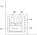
도 5는, 본 발명의 교시된 바와 원리에 따라 만들어지는 제어 유닛 디스플레이의 실시예를 예시한 도면.
도 6은, 본 발명의 교시된 바와 원리에 따라 만들어지는, 접은 또는 닫힌 위치에 제어 유닛의 접이식 디스플레이의 실시예를 예시한 도면.
도 6a는, 본 발명의 교시된 바와 원리에 따라 만들어지는, 열린 위치에 제어 유닛의 접이식 디스플레이의 실시예를 예시한 도면.
도 7은, 본 발명의 교시된 바와 원리에 따라 만들어지는 촬상장치 헤드의 실시예를 예시한 도면.
도 8은, 발명의 교시된 바와 원리에 따라 만들어지는 촬상장치 헤드의 실시예의 단면도.
도 9는, 발명의 교시된 바와 원리에 따라 만들어지는 촬상장치 헤드의 실시예의 단면도.
도 10은, 발명의 교시된 바와 원리에 따라 만들어지는 볼 조인트를 갖는 촬상장치 헤드의 실시예의 단면도.
도 11은, 발명의 교시된 바와 원리에 따라 만들어지는 촬상장치 헤드의 실시예의 단면도.
도 12는, 발명의 교시된 바와 원리에 따라 만들어지는 촬상 시스템의 실시예의 레이아웃도.
도 13은, 발명의 교시된 바와 원리에 따라 만들어지는 촬상 시스템의 실시예의 메모리의 개략도.
도 14는, 발명의 교시된 바와 원리에 따른 방법의 실시예를 예시한 도면.
도 15는, 발명의 교시된 바와 원리에 따른 방법의 실시예를 예시한 도면.
도 16은, 발명의 교시된 바와 원리에 따른 방법의 실시예를 예시한 도면.
도 17은, 발명의 교시된 바와 원리에 따른 방법의 실시예를 예시한 도면.
도 18은, 발명의 교시된 바와 원리에 따라 사용 후 촬상장치를 재활용하는 방법의 실시예를 예시한 도면.
도 19는, 교시된 바와 원리에 따라 살균 환경에서 사용을 위해 촬상장치를 제작하는 방법의 실시예를 예시한 도면.
도 20은, 촬상장치 시스템을 업데이트하는 방법의 실시예를 예시한 도면.
도 21은, 촬상장치 시스템에 업데이트를 제공하는 시스템의 실시예를 예시한 도면.The features and advantages of the invention will be apparent from a review of the following detailed description taken in conjunction with the accompanying drawings.
1 illustrates an embodiment of a feature of the present invention made in accordance with the teachings and principles of the present invention.
2 illustrates an embodiment of an imaging system made in accordance with the teachings and principles of the present invention.
3 illustrates an embodiment of an imaging system having a wireless feature made in accordance with the teachings and principles of the present invention.
4 illustrates an embodiment of a control unit, shown as detached from the imaging device but connected to the replenishment device, made in accordance with the teachings and principles of the present invention.
5 illustrates an embodiment of a control unit display made in accordance with the teachings and principles of the present invention.
6 illustrates an embodiment of a foldable display of a control unit in a folded or closed position, made according to the teachings and principles of the present invention.
6A illustrates an embodiment of a foldable display of a control unit in an open position, made in accordance with the teachings and principles of the present invention.
7 illustrates an embodiment of an imaging device head made in accordance with the teachings and principles of the present invention.
8 is a cross-sectional view of an embodiment of an imaging device head made in accordance with the teachings and principles of the invention.
9 is a cross-sectional view of an embodiment of an imaging device head made in accordance with the teachings and principles of the invention.
10 is a cross-sectional view of an embodiment of an imaging device head having a ball joint made in accordance with the teachings and principles of the invention.
11 is a cross-sectional view of an embodiment of an imaging device head made in accordance with the teachings and principles of the invention.
12 is a layout diagram of an embodiment of an imaging system made in accordance with the teachings and principles of the invention.
13 is a schematic diagram of a memory of an embodiment of an imaging system made in accordance with the teachings and principles of the invention.
14 illustrates an embodiment of a method in accordance with the teachings and principles of the invention.
15 illustrates an embodiment of a method in accordance with the teachings and principles of the invention.
16 illustrates an embodiment of a method in accordance with the teachings and principles of the invention.
17 illustrates an embodiment of a method in accordance with the teachings and principles of the invention.
18 illustrates an embodiment of a method of recycling an imaging device after use in accordance with the teachings and principles of the invention.
FIG. 19 illustrates an embodiment of a method of manufacturing an imaging device for use in a sterile environment in accordance with the teachings and principles.
20 illustrates an embodiment of a method of updating an imaging device system.
21 illustrates an embodiment of a system for providing an update to an imaging device system.
본 출원에 따른 원리의 이해를 촉진하기 위해, 도면에 예시된 실시예가 이제 참조될 것이고, 이를 설명하기 위해 특정한 언어가 사용될 것이다. 그러나, 본 출원의 범위를 제한하는 것이 의도되지 않았음을 이해할 수 있을 것이다. 본 출원에 예시된 발명의 특징의 임의의 변경과 추가 변형예, 및 본 출원에 예시된 바와 같은 본 출원의 원리의 임의의 추가 용도는, 당업자에게 일반적으로 일어나는 것으로, 청구된 본 발명의 범위 내에 있는 것으로 간주되어야 한다.In order to facilitate understanding of the principles according to the present application, the embodiments illustrated in the drawings will now be referenced, and specific language will be used to describe them. However, it will be understood that it is not intended to limit the scope of the present application. Any modifications and additional variations of the features of the invention illustrated in this application, and any further use of the principles of the present application as illustrated in the present application, generally occur to those skilled in the art, and are within the scope of the claimed invention. Should be considered to be present.
1회용 촬상장치를 제공하고 재활용하기 위한 장치, 시스템, 방법, 및 프로세스가 개시되고 기술되기 전에, 이 개시된 바는 본 출원에 개시된 특정 실시예, 구성 또는 프로세스 단계가 다소 다양할 수 있기 때문에 이들로 한정되는 것은 아님을 알아야 한다. 또한, 본 출원에서 채용된 용어는 특정 실시예를 기술할 목적으로만 사용되며 본 발명의 범위가 첨부된 청구항, 만약 있다면 이들의 등가물만으로 한정될 것이기 때문에 한정하려는 것이 아님도 알아야 한다.Before the devices, systems, methods, and processes for providing and recycling disposable imaging devices have been disclosed and described, this disclosure is directed to the specific embodiments, configurations, or process steps disclosed herein, as these may vary somewhat. It should be understood that it is not limited. It is also to be understood that the terminology employed herein is for the purpose of describing particular embodiments only, and is not intended to be limiting, since the scope of the present invention will be limited only by the appended claims, if any.
본 발명의 요지를 기술하고 청구할 때, 다음 용어가 아래 개시된 정의에 따라 사용될 것이다.In describing and claiming the subject matter of the present invention, the following terms will be used in accordance with the definitions disclosed below.
이 상세하 설명과 첨부된 청구항에 사용되는 바와 같이, 단수 형태는 문맥이 분명하게 다르게 지시하지 않는 한, 복수의 지시 대상을 포함한다는 것을 주의해야 한다.As used in this detailed description and the appended claims, it should be noted that the singular forms “a,” “an” and “the” include plural referents unless the context clearly dictates otherwise.
본 명세서에 사용되는 바와 같이, "포함하는", "함유하는", "~을 특징으로 하는"이라는 용어는, 추가의 인용되지 않은 요소 또는 방법 단계를 배제하지 않는 포괄적이거나 제한 없는 용어이다.As used herein, the terms "comprising", "containing", "characterized by" are generic or unlimited terms that do not exclude additional unquoted elements or method steps.
본 명세서에 사용된 바와 같이, "~로 구성되는"이라는 어구는, 청구항에 명시되지 않은 임의의 요소, 단계, 또는 구성요소를 포함한다.As used herein, the phrase “consisting of” includes any element, step, or component not specified in the claims.
본 명세서에 사용되는 바와 같이, "~로 필수 구성된"이라는 어구는, 특정된 물질 또는 단계, 및 청구된 발명의 기본적이고 신규한 특성 또는 특징에 실질적으로 영향을 미치지 않는 것으로 청구항의 범위를 제한한다.As used herein, the phrase “consisting essentially of” limits the scope of the claims to substantially no effect on the specified material or step and the basic and novel properties or characteristics of the claimed invention. .
주로 도 1을 참조하여, 본 발명의 특징의 실시예가 전반적으로 논의될 것이다. 도 1은 제어 유닛(120)에 전자적 및 물리적으로 결속될 수 있는 원격 촬상장치(110)를 사용하여 디지털 이미지를 제공하기 위한 시스템(100)을 도시한 것이다. 제어 유닛(120)은 수술실, 의사 진료실 또는 치과 진료실과 같은 살균 환경에서 1회용 기능 및 안전을 제공하기 위해 데이터를 촬상장치(110)와 교환하도록 구성될 수 있다. 또한, 제어 유닛(120)은 증가된 기능을 위해 컴퓨터(130) 또는 외부 모니터(140)에 전기적으로 연결될 수 있다.Mainly referring to FIG. 1, embodiments of features of the present invention will be discussed generally. 1 illustrates a
이제, 도 2를 참조하여 촬상 시스템(100)이 더 상세히 논의될 것이다. 도 2에 도시된 바와 같이, 촬상장치(110)는 제어 유닛(120) 상에 대응하는 전자 커넥터(126)와 전자적 및 물리적으로 상호작용하도록 구성되는 촬상장치(110) 상에 전자 커넥터(114)에 의해 제어 유닛(120)으로부터 연결 또는 분리될 수 있다. 제어 유닛(120)으로부터 촬상장치(110)를 분리하는 능력은 사용된 촬상장치(110)를 살균된, 재생된 촬상장치(110)로 쉽게 교체하는 능력을 제공한다. 촬상장치(110)는 일반적으로 전자 커넥터(114)로부터 원격에 위치된 헤드 부분(112)을 구비할 수 있어서, 사용하는 동안 헤드 부분(112)의 이동성이 더 커질 수 있게 한다.The
또한, 도 2는, 촬상장치(110)의 대응하는 전자 커넥터(114)를 수용하기 위해 전자 커넥터(126)를 내장한 제어 유닛(120)의 실시예를 예시한 것이다. 또한, 제어 유닛(120)은 수술 동안 정보를 조작자 또는 사용자에 전달하기 위한 디스플레이(128)를 구비할 수 있다. 또한, 디스플레이(128)는 조작자가 명령을 입력하거나 어떤 정보가 표시될지를 변경할 수 있게 하는 상호작용 기능을 포함할 수 있다. 이러한 기능은 일반적으로 공지된 바와 같은 터치 스크린 시스템에 의해 제공될 수 있다. 또한, 제어 유닛은 증가된 기능을 위해 이미지 데이터를 다른 장치에 전송하기 위한 비디오 입력(122) 및 비디오 출력(124)을 구비할 수 있다. 도 1에 도시된 바와 같이, 공통 장치는 컴퓨터(130) 또는 외부 모니터(140)일 수 있다.FIG. 2 also illustrates an embodiment of a
이제, 도 3을 참조하여 무선 능력 및 특징을 갖춘 촬상 시스템(300)이 논의될 것이다. 도 3에 도시된 바와 같이, 촬상장치(310)는, Wifi, 적외선, 블루투스 등과 같은 무선 전송에 의해 제어 유닛(320)과 통신할 수 있다. 임의의 가용 스펙트럼으로부터의 무선 주파수, 모든 구성의 적외선, 초음파, 및 광학을 포함하지만 이에 제한되지 않는, 촬상장치(310)와 제어 유닛(320) 사이에 통신을 제공하기 위한 다른 형태의 비테더형 무선 연결(wireless non-tethered connectivity)이 또한 사용될 수도 있다. 촬상장치(310)는 이하 상세히 논의될 촬상 센서, 메모리 및 연관된 회로를 수용하는 헤드 부분(312)을 포함할 수 있다. 헤드 부분(312)은 제어 유닛(320) 내 수용된 대응하는 무선 트랜스시버(322)와 통신하기 위한 무선 트랜스시버(314)를 더 포함할 수 있다. 무선 전송을 통해 헤드 부분(312)을 제어 유닛(320)으로부터 분리시킬 수 있는 능력은 사용된 촬상장치를 살균 및 재생된 촬상장치로 용이한 교체를 제공할 수 있다. 즉, 무선 통신은 위에 언급된 무선 기술 중 어느 것을 사용하여 상기 제어 유닛 상에 대응하는 트랜스시버와 무선 통신하도록 구성된 무선 통신 트랜스시버인 전자 통신회로에 의해 가능해질 수 있다. 또한, 무선 기능은 사용시 헤드 부분(312)의 이동성이 더 커지게 할 수 있다. 무선 특징 및 기능은 본 출원에 개시된 실시예 또는 본 발명의 범위 내에 속하는 실시예 중 어느 것에든 포함될 수 있음을 알 것이다.Referring now to FIG. 3, an
또한, 도 3은 무선 능력 및 특징을 갖는 제어 유닛(320)의 실시예를 예시한다. 트랜스시버(322)는 무선 데이터를 수신하고 촬상장치(310)에 송신하기 위해 제어 유닛(320) 내에 또는 이의 부분으로서 설치될 수 있다. 또한, 제어 유닛(320)은 수술 동안 정보를 조작자 또는 사용자에 전달하기 위한 디스플레이(328)를 구비할 수도 있다. 또한, 디스플레이(328)는 조작자가 명령을 입력하거나 어떤 정보가 표시되는지를 변경할 수 있도록 하는 상호작용 기능을 포함할 수 있다. 이러한 기능은 공지된 바와 같이 터치 스크린 시스템에 의해 제공될 수 있다. 또한, 제어 유닛(320)은 증가된 기능을 위해 이미지 데이터를 다른 장치에 전송하기 위한 비디오 입력(321) 및 비디오 출력(324)을 구비할 수 있다. 도 1에 도시된 바와 같이, 공통 장치는 컴퓨터(130) 또는 외부 모니터(140)일 수 있다. 유선 및 무선 통신 능력 모두가 포함된 촬상 시스템을 포함하는 것은 본 발명의 범위 내에 있다.3 also illustrates an embodiment of a
도 4는 보충 장치에 연결된 것으로서 예시된 촬상장치로부터 분리된 제어 유닛(420)의 실시예를 예시한 것이다. 커넥터(426)는 데이터를 촬상장치에 및 이로부터 전송하기 위해 설치될 수 있다. 촬상장치를 분리시킬 수 있는 능력은 사용된 촬상장치를 살균 및 재생된 촬상장치로 쉽게 교체하는 것을 제공할 수 있다. 또한, 제어 유닛(420)은 수술동안 조작자에게 정보를 전달하는 디스플레이(428)를 구비할 수도 있다. 또한, 디스플레이(428)는 조작자가 명령을 입력하거나 어떤 정보가 표시되도록 할지를 조작자가 변경할 수 있게 하는 상호작용 기능을 포함할 수 있다. 이러한 기능은 일반적으로 알려진 터치 스크린 시스템에 의해 제공될 수 있다. 또한, 제어 유닛은 증가된 기능을 위해 이미지 데이터를 다른 장치에 전송하기 위한 비디오 입력(421) 및 비디오 출력(424)을 구비할 수 있다. 공통 장치는 시스템(400)의 기술적 기능을 증가시켜 컴퓨터(430) 또는 외부 모니터(440)가 있을 수 있다. 컴퓨터(430)는 촬상 시스템으로부터 디지털 출력을 저장하기 위해 사용될 수 있고 또는 시스템 내에 다른 조절을 향상시키고 제공하기 위해 사용될 수도 있다. 시스템의 사용, 또는 기록된 디지털 영상을 나중에 검토하고 조사하는데 있어 조작자를 돕기 위해 실시간 디지털 영상을 보여주기 위해 사용될 수 있다.4 illustrates an embodiment of a
이제, 도 5를 참조하여, 제어 유닛(420)의 부분일 수도 있는 제어 유닛 디스플레이(428)의 실시예를 더 상세히 논의할 것이다. 디스플레이(428)는 액정 디자인(LCD)의 디지털 디스플레이일 수도 있고, 또는 디스플레이는 LCD외에 어떤 다른 기술일 수도 있으며 조작자 또는 사용자가 시스템(400)에 명령을 입력할 수 있도록 하는 터치 스크린 기능 및 능력을 구비할 수도 있다. 본 출원에서 논의되는 실시예는 조작자 또는 사용자가 시스템(400)에 명령을 입력할 수 있도록 하는 입력 부분(428a, 428b)을 구비할 수 있다. 실시예는 시스템(400)의 구성요소의 동작 상태에 관하여 사용자에게 알리는 상태 부분(428c)을 더 포함할 수 있다. 예를 들면, 디스플레이 부분(428c)은 촬상장치(410)가 이미 사용되거나 수술에 부적합한 것으로 여겨졌다면 부착된 촬상장치(410)의 상태에 관계된 에러 메시지를 디스플레이할 수 있다. 또한, 디스플레이(428)는 명령 및 추가 정보를 조작자 또는 사용자에게 제공하는 전용 메시지 부분(428d)을 구비할 수 있다. 디스플레이(428)의 구성은 추가 기능을 수용하기 위해 사용동안 변경할 수도 있다. 복수의 디스플레이(428)는 본 발명에 의해 고찰되고, 본 발명의 범위 내에 속하며 이 실시예에 대안적으로, 또는 이 실시예와 함께 사용될 수 있다. 실시예는 제어 유닛 내에 제어 목적을 위해 키 패드 또는 버튼 패드를 포함할 수 있다.Referring now to FIG. 5, an embodiment of the
도 6과 도 6a은 제어 유닛(420)의 접이식 디스플레이(428)의 실시예를 예시한 것이다. 디스플레이(428)는 이것이 사용되고 있지 않을 땐 이를 보호하기 위해 사용될 수 있는 제어 유닛(420)(도 6에 최상으로 도시된) 내 제1 또는 접은 위치를 가질 수 있다. 도 6a의 디스플레이(428')는 이것이 확장되어 밖으로 회전되었을 때, 어떻게 디스플레이가 더 많은 사용자 판독 가능 위치로 전개될 수 있는가를 도시한 것이다. 도 6과 도 6a에 예시된 바와 같이, 디스플레이는 통로 안과 밖으로 슬라이딩되고 디스플레이(428)를 광범위한 위치에서 배향하기 위해 축을 중심으로 회전할 수 있다.6 and 6A illustrate an embodiment of a
도 7은 촬상장치 헤드(712)의 일 실시예의 단면도이다. 촬상장치 헤드(712)는 플라스틱 또는 금속과 같은 적합하게 단단한 물질로 만들어진 하우징(710)을 포함할 수 있다. 하우징(710)은 내부 회로를 보호하고 살균 및 재생을 위한 적합한 표면을 제공하기 위해서 유체 및 기체에 대해 시일링될 수 있다. 촬상장치 헤드(712)는 촬상장치 헤드(712)의 조작을 위해 버튼(721, 722)을 갖는 사용자 입력 패널(720)을 더 포함할 수 있다. 추가의 버튼이 설치될 수 있고 버튼의 기능은 주어진 수술 또는 주어진 조작자에 맞게 맞춤화될 수 있다. 제어 패널(720)은 전기적 커넥터(726)에 의해 촬상장치 헤드(712)의 다른 회로에 내부적으로 연결될 수 있다.7 is a cross-sectional view of an embodiment of an
도 7에 추가 예시된 바와 같이, 촬상장치 헤드(712)는 나사상 보조구, 예를 들어, 1인치 나사상 보조구를 수용하기 위한 C-마운트 시스템과 같은 광학 마운트 시스템(750)을 포함할 수 있다. 또한, 윈도우(755)는 광이 광학 보조구에서 이미지 센서(775)로 용이하게 전송될 수 있게 실시예에 포함될 수 있다. 이미지 센서(775)는 지지 인쇄 회로 보드 또는 지지 기판(770)에 장착될 수 있다. 전자 커넥터(778)는 이미지 센서(775)를 주 회로 또는 주 인쇄회로 보드(760)에 전기적으로 연결하기 위해 포함될 수 있다. 주 배선 하니스(782)가 한 묶음의 와이어들(wired tether)(780)에 포함될 수 있어서, 촬상장치 헤드(712)의 구성요소를 제어 유닛에 전기적으로 연결할 수 있다.As further illustrated in FIG. 7, the
촬상장치 헤드(712)는 메모리(788) 또는 촬상장치 헤드(712) 내에 데이터를 저장할 수 있게 하는 메모리 회로를 더 포함할 수 있다. 메모리는 정보(데이터)를 기록(저장)할 수 있는 임의의 데이터 저장장치일 수 있음을 알 것이다. 메모리(788)에 저장 또는 기록될 수 있는 데이터는 촬상장치를 고유하게 식별하는 식별 일련 번호를 포함할 수 있다. 메모리(788)에 저장 또는 기록될 수 있는 그외 다른 데이터는 촬상장치가 사용된 시간의 양, 즉 작동 시간, 또는 촬상장치에 전원이 넣어져 있는 시간의 양과 같은 데이터를 포함할 수 있다. 메모리(788)에 기록될 수 있을 데이터는 촬상장치의 작동상태를 나타내는, 살균 데이터 또는 재생 데이터를 포함할 수 있다. 메모리(788)에 저장 또는 기록될 수 있는 데이터는 제조 일자, 최종 검증 또는 품질 관리 확인 일자, 제조 위치와 같은 데이터를 포함할 수 있는데, 즉 이름, 도시, 주, 도로 주소, 등, 촬상장치 헤드가 부착되었던 최종 제어 유닛, 촬상장치 헤드 진단 정보, 촬상장치 헤드를 위한 특정 수술 세팅, 또는 외과의사와 같은 조작자 또는 사용자에게 바람직한 세팅을 포함할 수 있다. 촬상장치의 전술한 특징, 또는 다른 표시를 나타내는 데이터는 촬상장치 내에 메모리에 기록될 수 있다.
메모리(788)는 탬퍼링(tampering) 또는 의도적이지 않은 사용을 피하기 위해 암호화 보호될 수 있다. 메모리(788)는 본 발명의 범위 내에서 촬상장치 헤드만이 아니라 촬상장치 내에 임의의 곳에 놓일 수 있음에 유의한다. 메모리(788)는 데이터 유지의 정도를 달리할 수 있는 영구적 또는 반영구적인 부분을 포함할 수 있다.
도 8은 촬상장치 헤드(812)의 실시예의 단면도이다. 촬상장치 헤드(812)는 플라스틱 또는 금속과 같은 적합하게 단단한 물질로 만들어진 하우징(810)을 포함할 수 있다. 하우징(810)은 내부 회로를 보호하고 살균 및 재생을 위한 적합한 표면을 제공하기 위해서 유체 및 기체에 대해 시일링될 수 있다. 촬상장치 헤드(812)는 버튼(821, 822)을 갖는 사용자 입력 패널(820)을 더 포함할 수 있다. 추가의 버튼이 설치될 수 있고, 버튼의 기능은 주어진 수술 또는 주어진 조작자에 맞게 맞춤화될 수 있다. 제어 패널(820)은 전기적 커넥터(826)에 의해 촬상장치 헤드(812)의 다른 회로에 내부적으로 연결될 수 있다.8 is a cross-sectional view of an embodiment of an
도 8의 실시예에 추가 예시된 바와 같이, 촬상장치 헤드(812)는 나사상 보조구, 예를 들면, 1인치 나사상 보조구를 수용하기 위한 C -마운트 시스템과 같은 광학 마운트 시스템(850)을 포함할 수 있다. 또한, 윈도우(855)는 광이 광학 보조구에서 이미지 센서(875)로 용이하게 전송될 수 있게 실시예에 포함될 수 있다. 이미지 센서(875)는 지지 인쇄회로 보드 지지 기판(870)에 장착될 수 있다. 전자 커넥터(878)는 이미지 센서(875)를 주 회로 또는 주 인쇄회로 보드(860)에 전기적으로 연결하기 위해 포함될 수 있다. 이미지 센서(875) 및 그외 회로로부터 방열을 제공하기 위해서, 열 싱크(861)가 설치될 수 있다. 열 싱크(861)는 이미지 센서(875)에 물리적으로 연결될 수 있고, 또한, 열 에너지가 촬상장치 헤드(812)의 외부 부분에 전도 또는 전달될 수 있게 하우징(810)에 연결될 수도 있다. 열 싱크(861)는 카메라 헤드가 CF(cardiac floating) 및 BF(body floating) ISO 규격을 충족시킬 수 있게 외부에 노출된 중립 센서 열 싱크 일 수 있다. 열 싱크(861)의 실시예는 알루미늄으로 만들어지고 추가된 전열 표면적을 위한 핀(fin)을 가질 수도 있다. 주 배선 하니스(882)는 한 묶음의 와이어들(880)에 포함되어, 촬상장치 헤드(812)의 구성요소를 제어 유닛에 전기적으로 연결할 수 있다.As further illustrated in the embodiment of FIG. 8,
촬상장치 헤드(812)는 메모리(888) 또는 촬상장치 헤드(812) 내에 데이터를 저장할 수 있게 하는 메모리 회로를 더 포함할 수 있다. 메모리(888)에 저장 또는 기록될 수 있는 데이터는 촬상장치를 고유하게 식별하는 식별 일련 번호를 포함할 수 있다. 메모리(888)에 저장 또는 기록될 수 있는 그외 다른 데이터는 촬상장치가 사용된 시간의 양, 즉 작동 시간, 또는 촬상장치에 전원이 넣어져 있는 시간의 양과 같은 데이터를 포함할 수 있다. 메모리(888)에 기록될 수 있을 데이터는 촬상장치의 작동 상태를 나타내는, 살균 데이터 또는 재생 데이터를 포함할 수 있다. 메모리(888)에 저장 또는 기록될 수 있는 데이터는 제조 일자, 최종 검증 또는 품질 관리 확인 일자, 제조 위치와 같은 데이터를 포함할 수 있는데, 즉 이름, 도시, 주, 도로 주소, 등, 촬상장치 헤드가 부착되었던 최종 제어 유닛, 촬상장치 헤드 진단 정보, 촬상장치 헤드를 위한 특정 수술 세팅, 또는 외과의사와 같은 조작자 또는 사용자에게 바람직한 세팅을 포함할 수 있다. 촬상장치의 전술한 특징, 또는 그외 표시를 나타내는 데이터가 촬상장치 내에 메모리에 기록될 수 있다.The
메모리(888)는 탬퍼링 또는 의도하지 않은 사용을 피하기 위해 암호화 보호될 수 있다. 메모리는 본 발명의 범위 내에서 촬상장치 헤드만이 아니라 촬상장치 내에 임의의 곳에 놓일 수 있음에 유의한다. 메모리(888)는 데이터 유지의 정도를 달리할 수 있는 영구적 또는 반-영구적 부분을 포함할 수 있다.
도 9는 촬상장치 헤드(912)의 실시예의 단면도이다. 촬상장치 헤드(912)는 플라스틱 또는 금속과 같은 적합하게 단단한 물질로 만들어진 하우징(910)을 포함할 수 있다. 하우징(910)은 내부 회로를 보호하고 살균 및 재생을 위한 적합한 표면을 제공하기 위해서 유체 및 기체에 대해 시일링될 수 있다. 촬상장치 헤드(912)는 버튼(921, 922)을 갖는 사용자 입력 패널(920)을 더 포함할 수 있다. 추가의 버튼이 설치될 수 있고 버튼의 기능은 주어진 수술 또는 주어진 조작자에 맞게 맞춤화될 수 있다. 제어 패널(920)은 전기적 커넥터(926)에 의해 촬상장치 헤드(912)의 다른 회로에 내부적으로 연결될 수 있다.9 is a sectional view of an embodiment of an
도 9의 실시예에 추가 예시된 바와 같이, 촬상장치 헤드(912)는 나사상 보조구, 예를 들어, 1인치 나사상 보조구를 수용하기 위한 C -마운트 시스템과 같은 광학 마운트 시스템(950)을 포함할 수 있다. 또한, 윈도우(955)는 광이 광학 보조구에서 이미지 센서(975)로 용이하게 전송될 수 있도록 실시예에 포함될 수 있다. 이미지 센서(975)는 지지 인쇄회로 보드 또는 지지 기판(970)에 장착될 수 있다. 전자 커넥터(978)는 이미지 센서(975)를 주 회로 또는 주 인쇄회로 보드(960)에 전기적으로 연결하기 위해 포함될 수 있다. 이미지 센서(975) 및 다른 회로로부터 방열을 제공하기 위해서, 도 8에 제공된 열 싱크와 유사하게, 열 싱크가 설치될 수 있다. 열 싱크는 이미지 센서(975)에 물리적으로 연결될 수 있고, 또한, 열 에너지가 촬상장치 헤드(912)의 외부 부분에 전도 똔느 전달될 수 있게 하우징(910)에 연결될 수도 있다. 주 배선 하니스(982)는 한 묶음의 와이어들(980)에 포함되어, 촬상장치 헤드(912)의 구성요소를 제어 유닛에 전기적으로 연결할 수 있다.As further illustrated in the embodiment of FIG. 9, the
촬상장치 헤드(912)는 메모리(988) 또는 촬상장치 헤드(912) 내에 데이터를 저장할 수 있도록 하는 메모리 회로를 더 포함할 수 있다. 메모리(988)에 저장 또는 기록될 수 있는 데이터는 촬상장치를 고유하게 식별하는 식별 일련 번호를 포함할 수 있다. 메모리(988)에 저장 또는 기록될 수 있는 그외 다른 데이터는 촬상장치가 사용된 시간의 양, 즉 작동 시간, 또는 촬상장치에 전원이 넣어져 있는 시간의 양과 같은 데이터를 포함할 수 있다. 메모리(988)에 저장 또는 기록될 수 있는 데이터는 제조 일자, 최종 검증 또는 품질 관리 확인 일자, 제조 위치와 같은 데이터를 포함할 수 있는데, 즉 이름, 도시, 주, 도로 주소, 등, 촬상장치 헤드가 부착되었던 최종 제어 유닛, 촬상장치 헤드 진단 정보, 촬상장치 헤드를 위한 특정 수술 세팅, 또는 외과의사와 같은 조작자 또는 사용자에게 바람직한 세팅을 포함할 수 있다. 촬상장치의 전술한 특징, 또는 다른 표시를 나타내는 데이터가 촬상장치 내에 메모리에 기록될 수 있다.The
메모리(988)는 탬퍼링 또는 의도하지 않은 사용을 피하기 위해 암호화 보호될 수 있다. 메모리는 본 발명의 범위 내에서 촬상장치 헤드뿐만 아니라, 촬상장치 내에 임의의 곳에 놓일 수 있음에 유의한다. 메모리(988)는 데이터 유지의 정도를 달리할 수 있는 영구적 또는 반-영구적 부분을 포함할 수 있다.
촬상장치 헤드(912)는 대응하는 시일 및 소켓을 갖는 볼 조인트(990)를 포함하여, 조작자 또는 사용자에 의한 촬상장치의 관절 동안 하우징(910)과 결속(980) 사이에 증가된 이동성을 제공할 수 있다.The
주로 도 10을 참조하여, 촬상장치의 볼 조인트(990)의 실시예를 더 상세히 논의할 것이다. 도 10은 한 묶음의 와이어들(980)에 관하여 촬상장치 헤드(912)를 이동할 때 조작자에게 더 큰 관절 자유도를 제공하는 볼 조인트(990)의 단면도를 도시한 것이다. 볼 조인트(990)는 실질적으로 구형의 회전 가능한 부분 또는 볼(991)을 포함할 수 있다. 볼(991)은 볼(991)이 소켓(992) 내에 유지되면서 실질적으로 자유롭게 회전할 수 있게, 대응하는 소켓(992)과 연동하여 기계적으로 동작하도록 구성될 수 있다. 시일은 시일 링(993)의 포함에 의해 볼 조인트(990) 내에 제공될 수 있다. 또한, 시일 링(993)은 볼 조인트(990) 내에 기계적 저항을 제공할 수 있다. 볼(991)은 배선(995)이 볼 조인트(990)를 지나갈 수 있게 볼(991)을 관통하는 개구(994)를 더 포함할 수 있다.Mainly referring to FIG. 10, an embodiment of the ball joint 990 of the imaging device will be discussed in more detail. FIG. 10 shows a cross-sectional view of the ball joint 990 which gives the operator greater joint freedom when moving the
도 11을 참조하여, 무선 전송 기능을 포함하는 촬상장치(1100)의 실시예를 논의할 것이다. 촬상장치 헤드(1112)의 실시예의 단면도가 도 11에 도시되었다. 촬상장치 헤드(1112)는 플라스틱 또는 금속과 같은 적합하게 단단한 물질로 만들어진 하우징(1110)을 포함할 수 있다. 하우징(1110)은 내부 회로를 보호하고 살균 및 재생을 위한 적합한 표면을 제공하기 위해서 유체 및 기체에 대해 시일링될 수 있다. 촬상장치 헤드(1112)는 버튼(1121, 1122)을 갖는 사용자 입력 패널(1120)을 더 포함할 수 있다. 추가의 버튼이 설치될 수 있고 버튼의 기능은 주어진 수술 또는 주어진 조작자에 맞게 맞춤화될 수 있다. 제어 패널(1120)은 내부에서 전기적 커넥터(1126)에 의해 촬상장치 헤드(1112)의 다른 회로에 연결될 수 있다. 촬상장치 헤드(1112)는 Wifi, 적외선, 블루투스 등과 같은 무선 전송에 의해 제어 유닛과 통신할 수 있다. 임의의 가용 스펙트럼으로부터의 무선 주파수, 모든 구성의 적외선, 초음파, 및 광학을 포함하지만 이에 제한되지 않는, 촬상장치 헤드(1112)와 제어 유닛 사이에 통신을 제공하기 위한 다른 형태의 비테더형 무선 연결이 또한 사용될 수 있다.Referring to FIG. 11, an embodiment of an
도 11의 실시예에 추가 예시된 바와 같이, 촬상장치 헤드(1112)는 나사상 보조구, 예를 들어, 1인치 나사상 보조구를 수용하기 위한 C -마운트 시스템과 같은 광학 마운트 시스템(1150)을 포함할 수 있다. 또한, 윈도우(1155)는 광이 광학 보조구에서 이미지 센서(1175)로 용이하게 전송될 수 있게 실시예에 포함될 수 있다. 이미지 센서(1175)는 지지 인쇄회로 보드 또는 지지 기판(1170)에 장착될 수 있다. 전자 커넥터(1178)는 이미지 센서(1175)를 주 회로 또는 주 인쇄회로 보드(1160)에 전기적으로 연결하기 위해 포함될 수 있다. 촬상장치 헤드(1112)의 회로는 도 3에 도시된 바와 같은 무선으로 구성되는 제어 유닛으로부터 데이터를 송신 및 수신하기 위한 무선 트랜스시버(1111)에 전기적으로 연결될 수 있다.As further illustrated in the embodiment of FIG. 11, the imaging device head 1112 is an
촬상장치 헤드(1112)는 메모리(1188) 또는 촬상장치 헤드(1112) 내에 데이터를 저장할 수 있게 하는 메모리 회로를 더 포함할 수 있다. 메모리(1188)에 저장 또는 기록될 수 있는 데이터는 촬상장치를 고유하게 식별하는 식별 일련 번호를 포함할 수 있다. 메모리(1188)에 저장 또는 기록될 수 있는 그외 다른 데이터는 촬상장치가 사용된 시간의 양, 즉 작동 시간, 또는 촬상장치에 전원이 넣어져 있는 시간의 양과 같은 데이터를 포함할 수 있다. 메모리(1188)에 저장 또는 기록될 수 있는 데이터는 제조 일자, 최종 검증 또는 품질 관리 확인 일자, 제조 위치와 같은 데이터를 포함할 수 있는데, 즉 이름, 도시, 주, 도로 주소, 등, 촬상장치 헤드가 부착되었던 최종 제어 유닛, 촬상장치 헤드 진단 정보, 촬상장치 헤드를 위한 특정 수술 세팅, 또는 외과의사와 같은 조작자 또는 사용자에게 바람직한 세팅을 포함할 수 있다. 촬상장치의 전술한 특징, 또는 다른 표시를 나타내는 데이터가 촬상장치 내에 메모리에 기록될 수 있다.The imaging device head 1112 may further include a memory circuit for enabling data to be stored in the
메모리(1188)는 탬퍼링 또는 의도하지 않은 사용을 피하기 위해 암호화 보호될 수 있다. 메모리는 본 발명의 범위 내에서 촬상장치 헤드만이 아니라 촬상장치 내에 임의의 곳에 놓일 수 있음에 유의한다. 메모리(1188)는 데이터 유지의 정도를 달리할 수 있는 영구적 또는 반-영구적 부분을 포함할 수 있다.
도 9 및 도 10에 도시된 볼 조인트는 본 발명의 정신 또는 범위 내에서 본 발명의 임의의 실시예에 의해 사용될 수 있음을 알 것이다. 따라서, 예를 들면, 볼 조인트(990)는 촬상장치 헤드(712, 812, 912, 또는 1112)에 사용될 수 있다. 유사하게, 열 싱크(861)(도 8에 도시된)는 본 발명의 범위 내에서 본 발명의 임의의 실시예에 의해 사용될 수 있음을 알 것이다.It will be appreciated that the ball joints shown in FIGS. 9 and 10 can be used by any embodiment of the present invention within the spirit or scope of the present invention. Thus, for example, the ball joint 990 can be used for the
이제, 도 12를 참조하여 살균 환경에서 영상을 획득하기 위한 시스템의 실시예가 논의될 것이다. 시스템은 메모리(1202), 이미지 센서(1204), 및 지지회로(1206)를 갖는 촬상장치(1201)를 포함할 수 있다. 시스템은 프로세서(1221), 시간 회로 또는 실시간 클럭(1222), 카운트 또는 증분 회로(1224) 및 제어 유닛 메모리(1226)를 갖는 제어 유닛(1220)을 더 포함할 수 있다. 구성요소는 일반적으로 하우징 내 제공될 것이지만 그러나 여기에서는 간이성과 논의 목적을 위해 블록도 형태로 도시되었다. 위에 회로 중 어느 것이든 제어 유닛 또는 촬상장치로부터 동작할 수 있을 것임이 생각된다.An embodiment of a system for obtaining images in a sterile environment will now be discussed with reference to FIG. 12. The system may include an
도 13에서 알 수 있는 바와 같이, 촬상장치(1201)의 메모리(1202)는 다음 배열의 데이터 저장을 포함할 수 있다:As can be seen in FIG. 13, the
a. 카메라 헤드 작동 시간;a. Camera head operating time;
b. 카메라가 사용된 횟수;b. The number of times the camera has been used;
c. 고유 식별, 즉 일련 번호, id, 등;c. Unique identification, ie serial number, id, etc .;
d. 제조 일자;d. Date of Manufacture;
e. 최종 검증/품질 확인 일자;e. Date of last verification / quality check;
f. 제조 위치, 즉 (주소, 주, 도시, 등);f. Manufacturing location, i.e. (address, state, city, etc.);
g. 카메라 헤드가 연결된 최종 콘솔;g. A final console to which the camera head is connected;
h. 카메라 콘솔 진단 정보;h. Camera console diagnostic information;
i. 수술에 특정한 카메라 헤드 세팅(즉 비디오 세팅, 버튼 세팅, 등);i. Camera head settings specific to the surgery (ie, video settings, button settings, etc.);
j. 최종 살균 일자(제품에 안전을 보증하기 위해 사용되는); 및j. Final sterilization date (used to ensure safety of the product); And
k. 외과의사 세팅.k. Surgeon settings.
촬상장치를 개선하고 본 발명의 범위 내에 있을 것으로 간주되는 추가의 데이터가 메모리(1202) 내에 저장될 수 있다.Additional data may be stored in the
도 14를 참조하여, 본 출원에 개시된 실시예에 일관된 촬상 시스템을 사용하는 방법이 논의될 것이다. 사용시, 1410에서 메모리(1202)를 포함할 수 있는 살균 1회용 촬상장치(1201)가 제공될 것이다. 1420에서, 사용자는 1회용 촬상장치(1201)를 전자적 및 물리적으로 보충 제어 유닛(1220)에 연결할 수 있다. 1430에서, 제어 유닛(1220)은 메모리(1202)를 판독하는 프로세스를 개시하고 촬상장치(1201)의 일련 번호를 등록한다. 1440에서, 시스템은 촬상장치(1201)가 사용된 값이 메모리(1202)에 기록되도록 한다. 1450에서, 시스템은 촬상장치(1201)가 제어 유닛(1220)에 연결되는 일자와 시간을 메모리(1202)에 기록한다. 1460에서, 타이밍 프로세스는 1450에서 기록된 기준선 시간으로부터 제어 유닛에 의해 개시되며 촬상장치(1201)가 사용되는 기간을 추적하거나 시간을 재고 기간이 1470에서 메모리(1202)에 기록된다. 사용 후, 촬상장치(1201)는 1480에서 제어 유닛(1220)으로부터 분리되고 이어 재생 또는 재활용을 위해 폐기된다.Referring to FIG. 14, a method of using a consistent imaging system in the embodiments disclosed in this application will be discussed. In use, a sterile
이제, 도 15를 참조하여, 1회용 촬상장치(1201)를 재생하여 재활용하는 방법이 논의될 것이다. 1510에서, 촬상장치(1201)는 테스트 제어 유닛 또는 마스터 제어 유닛에 연결될 수 있다. 1520에서, 테스트 제어 유닛 또는 마스터 제어 유닛은 특정 촬상장치(1201)가 재생되기 위해서, 메모리(1202) 내 저장된 데이터가 테스트 제어 유닛 또는 마스터 제어 유닛 상에 저장장치에 저장시 기록되도록 한다. 1525에서, 촬상장치가 재생되었고 이를 사용하기 위해 다른 제어 유닛에 연결될 때 동작하게 사용할 준비가 된 것을 나타내는 값이 메모리(1202)에 놓인다. 재생 위치 및 일자는 1530에서 메모리(1202)에 기록될 수 있다. 1540에서, 촬상장치(1201)는 살균되고, (1550에서) 보호용 살균 포장에 놓일 수 있다.Now, referring to FIG. 15, a method of reproducing and recycling the
도 16을 참조하여, 실시예의 안전 세팅을 예시하여 사용 방법의 대안적 실시예가 논의될 것이다. 1610에서, 메모리 촬상장치 헤드는 현장에서, 즉, 수술실에서 조립 후에, 그리고 품질 관리 확인이 수행된 후에 마스터 제어 유닛 또는 마스터 콘솔에 플러그인 되었을 때 제조시간이 스탬프될 수 있다. 1620에서, 전형적인 살균 사이클이 지속하게 되는 것에 가까운 시간 프레임과 같은 미리 결정된 몇 분 동안 촬상장치가 전원이 꺼졌는지를 판정하는 확인이 행해질 수 있다. 1630에서, 촬상장치가 미리 결정된 시간의 양 동안 전원이 꺼졌다면, 제어 유닛은 촬상장치가 이미 사용되었음을 사용자에게 알리는 온스크린 메시지를 디스플레이할 것이며, 더 이상의 동작을 허용하지 않고 이에 따라 어떠한 이미지도 비디오 피드를 통해 생성되지 않을 것이다. 이 특징은 촬상장치, 즉 카메라가 살균 사이클당 1회 이상 사용되지 않게 할 것이다. 또한, 이 특징은 무효한 또는 안전하지 않은 사용으로부터 환자 및 의사를 보호한다.With reference to FIG. 16, an alternative embodiment of the method of use will be discussed by illustrating the safety setting of the embodiment. At 1610, the memory imaging device head may be stamped with manufacturing time when it is plugged into the master control unit or master console after assembly in the field, ie in the operating room, and after quality control checks have been performed. At 1620, confirmation may be made to determine if the imaging device has been powered off for a predetermined number of minutes, such as a time frame close to where a typical sterilization cycle will last. At 1630, if the imager has been powered off for a predetermined amount of time, the control unit will display an on-screen message informing the user that the imager has already been used, allowing no further operation and thus no image is displayed. It will not be generated through the feed. This feature will prevent the imaging device, ie the camera, from being used more than once per sterilization cycle. This feature also protects patients and physicians from invalid or unsafe use.
도 17을 참조하여 사용 방법의 실시예가 논의될 것이다. 사용시, 촬상장치가 제어 유닛에 연결될 수 있다. 연결시, 촬상장치와 제어 유닛 사이에 전자 통신 연결이 형성된다. 1702에서, 촬상장치는 제어 유닛에 의해 공급되는 파워에 의해 전원이 공급될 수 있다. 1704에서, 제어 유닛 내 프로세서는 촬상장치 내에 메모리에 저장될 수 있는 촬상장치 식별에 관한 데이터가 판독되도록 할 수 있다. 1706에서, 제어 유닛 내 프로세서는 촬상장치의 제조 일자에 관한 데이터가 촬상장치 내에 메모리로부터 판독되도록 할 수 있다. 이어서, 제어 유닛 내 프로세서는 데이터를 미리 결정된 데이터 값 범위와 비교할 수 있다. 1707에서, 판독된 데이터가 미리 결정된 데이터 값 범위 밖에 있으면 에러 메시지가 표시될 수 있고 촬상장치는 동작으로부터 정지될 것이다. 1708에서, 제어 유닛 내 프로세서는 촬상장치의 재활용에 관한 데이터가 촬상장치 내 메모리로부터 판독되도록 할 수 있다. 촬상장치의 재활용에 관한 데이터는 촬상장치가 이전에 사용되었는지 여부를 나타내는 데이터를 포함할 수 있다. 이어서, 프로세서는 데이터를 미리 결정된 데이터 값 범위와 비교할 수 있다. 1709에서, 판독된 데이터가 미리 결정된 데이터 값 범위 밖에 있으면 에러 메시지가 표시될 수 있고 촬상장치는 동작으로부터 정지될 것이다. 1710에서, 제어 유닛 내 프로세서는 촬상장치의 재활용 일자에 관한 데이터가 촬상장치 내에 메모리로부터 판독될 수 있게 한다. 이어서, 프로세서는 데이터를 미리 결정된 데이터 값 범위와 비교할 수 있다. 1711에서, 판독된 데이터가 미리 결정된 데이터 값 범위 밖에 있으면 에러 메시지가 표시될 수 있고, 촬상장치는 동작으로부터 정지될 것이다. 1712에서, 제어 유닛 내 프로세서는 미리 결정된 기간 동안 촬상장치가 전원이 공급되지 않았고 이어 다시 전원이 재개되었는지를 알기 위해서 현재 수술의 사용 정보가 모니터되도록 할 있다. 이 상태가 일어난다면 촬상장치는 탬퍼링되었거나 촬상장치를 살균하고 이를 두 번째로 사용하려는 시도가 행해졌을 것임이 가능하다. 미리 결정된 시간은 전형적인 살균 프로세스에 통상적으로 걸리게 되는 시간의 양에 대응할 수 있다. 이어서, 프로세서는 데이터를 미리 결정된 데이터 값 범위와 비교한다. 1713에서, 판독된 데이터가 미리 결정된 데이터 값 범위 밖에 있으면 에러 메시지가 표시될 수 있고, 촬상장치는 동작으로부터 정지될 것이다. 1714에서, 제어 유닛 내 프로세서는 촬상장치가 사용되었음을 나타내는 값이 촬상장치 내 메모리에 저장되도록 할 수 있다. 1716에서, 제어 유닛 내 프로세서는 사용 일자와 시간이 촬상장치 내 메모리에 기록되도록 할 수 있다. 촬상장치의 메모리에 예를 들면, 기간, 수술 세팅, 및 사용자 세팅 및 이외 메모리에 기록하는데 적합한 어떤 다른 데이터와 같은 추가의 정보가 기록될 수 있다. 촬상장치는 제어 유닛으로부터 분리되어 1718에서 전원이 꺼질 수 있다.An embodiment of a method of use will be discussed with reference to FIG. 17. In use, the imaging device can be connected to the control unit. In connection, an electronic communication connection is formed between the imaging device and the control unit. At 1702, the imaging device may be powered by the power supplied by the control unit. At 1704, the processor in the control unit may cause the data relating to the imager identification to be read out to be stored in the memory in the imager. At 1706, the processor in the control unit may cause data relating to the date of manufacture of the imaging device to be read from the memory in the imaging device. The processor in the control unit can then compare the data with a predetermined range of data values. At 1707, an error message may be displayed if the read data is outside the predetermined data value range and the imaging device will stop from operation. At 1708, the processor in the control unit can cause data relating to recycling of the imaging device to be read from the memory in the imaging device. Data relating to recycling of the imaging device may include data indicating whether the imaging device has been previously used. The processor may then compare the data with a predetermined range of data values. At 1709, an error message may be displayed if the read data is outside the predetermined data value range and the imaging device will stop from operation. At 1710, the processor in the control unit allows data relating to the recycling date of the imaging device to be read from the memory in the imaging device. The processor may then compare the data with a predetermined range of data values. At 1711, an error message may be displayed if the read data is outside the predetermined data value range, and the imaging device will stop from operation. At 1712, the processor in the control unit may cause the usage information of the current surgery to be monitored to see if the imaging device has not been powered for a predetermined period of time and then again has power resumed. If this condition occurs, it is possible that the imaging device has been tampered or an attempt has been made to sterilize the imaging device and use it a second time. The predetermined time may correspond to the amount of time that would typically take for a typical sterilization process. The processor then compares the data with a predetermined range of data values. At 1713, an error message may be displayed if the read data is outside the predetermined data value range, and the imaging device will stop from operation. At 1714, the processor in the control unit may cause a value indicating that the imaging device has been used to be stored in a memory in the imaging device. At 1716, the processor in the control unit may cause the date and time of use to be recorded in a memory in the imaging device. Additional information such as, for example, duration, surgical settings, and user settings and any other data suitable for recording in the memory may be recorded in the memory of the imaging device. The imaging device may be detached from the control unit and turned off at 1718.
이제, 도 18을 참조하여, 사용 후 이미지 장치를 재활용하는 방법이 논의될 것이다. 1회용 촬상장치는 복수 회 사용되는 내구성을 포함할 수 있으나, 살균 요건은 촬상장치를 재활용하여 이를 살균상태로 되돌리는 프로세스 없이는 1회 이상 촬상장치가 사용되지 못하게 하는 것에 유의한다. 촬상장치를 재활용하는 방법은, 촬상장치가 제어 유닛에 전기적으로 연결되었을 때, 1802에서 촬상장치에 파워를 넣는 프로세스를 포함할 수 있다. 1804에서, 제어 유닛 내 프로세서는 촬상장치에 대한 식별 정보를 나타내는 데이터가 제어 유닛 내 저장장치에 저장되도록 할 수 있다. 제어 유닛은 촬상장치를 재활용하도록 구성된 마스터 제어 유닛일 수 있다. 마스터 제어 유닛은 복수의 촬상장치를 추적하여 장치 또는 장치의 사용 및 상태와 같은 연관된 정보의 카탈로그를 유지할 수 있다. 1806에서, 제어 유닛 내 프로세서는 제조 일자를 나타내는 이 데이터가 판독되고 미리 결정된 값 또는 범위의 값과 비교될 수 있게 한다. 판독된 데이터가 미리 결정된 범위 값 밖에 있으면, 1807에서 오류 레포트가 발행될 수 있다. 1808에서, 제어 유닛 내 프로세서는 촬상장치의 메모리에 기록된 사용 데이터를 나타내는 데이터가 판독되어 제어 유닛 내 저장장치에 기록되도록 할 수 있다. 1810에서, 프로세서는 재활용 일자와 시간을 나타내는 데이터가 촬상장치 내 메모리에 기록되도록 할 수 있다. 1812에서, 제어 유닛 내 프로세서는 촬상장치의 사용 횟수가 판독되어 제어 유닛 내 저장장치에 기록될 수 있게 한다. 프로세서는 판독된 데이터를 미리 결정된 값 또는 범위의 값과 비교하여 촬상장치가 계속된 사용에 적합한지 여부를 판정할 수 있다. 미리 결정된 값이 초과되면 에러 메시지가 표시되고 (1813에서) 촬상장치는 폐기될 수 있다. 1814에서, 제어 유닛 내 프로세서는 장치가 기능함을 보증하기 위해서 촬상장치 내 모든 회로의 테스트 또는 품질 관리 확인을 개시할 수 있다. 1815에서, 촬상장치는 품질 관리 확인에 실패한 것으로 판정되어 에러 메시지가 표시될 수도 있다. 1816에서, 촬상장치는 사용을 위해 리셋될 수 있다. 리셋 프로세스는 촬상장치가 재활용되고 살균되었음을 나타내는 데이터를 촬상장치의 메모리에 기록하는 것을 포함할 수 있다. 1816에서, 장치는 제어 유닛으로부터 분리되고 물리적으로 살균되고 다시 포장될 수 있다.Referring now to FIG. 18, a method of recycling an image device after use will be discussed. Although the disposable imaging device may include durability used multiple times, it is noted that the sterilization requirement prevents the imaging device from being used more than once without the process of recycling the imaging device and returning it to the sterilization state. The method of recycling the imaging device may include a process of powering on the imaging device at 1802 when the imaging device is electrically connected to the control unit. At 1804, the processor in the control unit may cause data indicative of identification information for the imaging device to be stored in storage in the control unit. The control unit may be a master control unit configured to recycle the imaging device. The master control unit may track a plurality of imaging devices to maintain a catalog of associated information, such as the device or its use and status. At 1806, the processor in the control unit allows this data indicative of the date of manufacture to be read and compared to a value in a predetermined value or range. If the read data is outside the predetermined range value, an error report may be issued at 1807. At 1808, the processor in the control unit may cause the data representing the usage data recorded in the memory of the imaging device to be read and written to the storage in the control unit. At 1810, the processor may cause data indicative of the recycling date and time to be recorded in a memory in the imaging device. At 1812, the processor in the control unit allows the number of times of use of the imaging device to be read and written to the storage in the control unit. The processor may compare the read data with a value of a predetermined value or range to determine whether the imaging device is suitable for continued use. If the predetermined value is exceeded, an error message is displayed (at 1813) and the imaging device may be discarded. At 1814, the processor in the control unit may initiate a test or quality control check of all circuitry in the imaging device to ensure that the device is functional. At 1815, the imaging device may be determined to have failed the quality control check and an error message may be displayed. At 1816, the imaging device can be reset for use. The reset process may include writing data into the memory of the imaging device indicating that the imaging device has been recycled and sterilized. At 1816, the device may be detached from the control unit, physically sterilized and repackaged.
주로 도 19를 참조하여, 살균 환경에서 사용하기 위해 메모리를 구비한 촬상장치를 제조하는 방법의 실시예가 논의될 것이다. 1902에서, 촬상장치가 제어 유닛에 연결될 때 전원이 넣어질 수 있다. 제어 유닛은 제조 프로세스를 위해 구성된 마스터 제어 유닛일 수 있다. 1904에서, 제어 유닛 내 프로세서는 촬상장치에 대한 식별 일련 번호를 나타내는 데이터가 촬상장치의 메모리에 기록되도록 할 수 있다. 1906에서, 제어 유닛 내 프로세서는 제조 위치를 나타내는 데이터가 촬상장치 내 메모리에 기록되도록 할 수 있다. 1908에서, 프로세서는 제조 일자를 나타내는 데이터가 촬상장치 상의 메모리에 기록되도록 할 수 있다. 1910에서, 제어 유닛 내 프로세서는 장치가 기능함을 보증하기 위해 촬상장치 내 모든 회로의 테스트 또는 품질 관리 확인을 개시할 수 있다. 1912에서, 촬상장치는 제어로부터 언플러그되고 포장을 위해 살균될 수 있다.Mainly referring to FIG. 19, an embodiment of a method of manufacturing an imaging device with a memory for use in a sterile environment will be discussed. At 1902, power can be turned on when the imaging device is connected to the control unit. The control unit may be a master control unit configured for the manufacturing process. At 1904, the processor in the control unit can cause data indicative of the identification serial number for the imaging device to be recorded in the memory of the imaging device. At 1906, the processor in the control unit may cause data indicative of the manufacturing location to be written to a memory in the imaging device. At 1908, the processor may cause data indicative of the date of manufacture to be written to a memory on the imaging device. At 1910, the processor in the control unit may initiate a test or quality control check of all circuitry in the imaging device to ensure that the device is functional. At 1912, the imaging device can be unplugged from control and sterilized for packaging.
도 20에 도시된 실시예를 참조하여, 촬상장치를 사용할 권한이 부여된 것을 검증하기 위해서 사용을 위해 제어 유닛에 의해 촬상장치를 확인하고 인증하는 보안 코드 또는 이외 어떤 다른 수단을 구비한 시스템을 이제 기술할 것이다. 인증 보안 코드 또는 인증의 동작은 메모리를 내장한 USB 장치와 같은 휴대 저장장치, 또는 다른 컴퓨터, 또는 다른 저장장치로부터 직업 전송에 의해, 인터넷을 통해 중앙 데이터베이스로부터, 제어 유닛에 분배될 수 있다. 도 20을 참조하여, 의료 촬상 시스템에서 업데이트를 제공하기 위한 방법의 실시예가 논의될 것이다. 2002에서, 보안 업데이트를 수신하기 위해 제어 유닛에 전원이 넣어질 수 있다. 2004에서, 제어 유닛에 연결될 촬상장치에 대응하는 인증 코드를 포함하는 보안 업데이트 데이터가 제공될 수 있다. 이러한 인증 코드는 제조업자 또는 분배자에 의해 사용되지 못하게 선택된 촬상장치를 시스템의 사용자가 사용하지 못하게 할 수 있음을 시스템이 보증할 수 있게 한다. 사용되지 못하게 하는 선택 기준은 안전 고찰, 리콜 고찰, 위조방지 조치, 및 판매와 계약 고찰을 포함할 수 있다. 2006에서, 데이터는 촬상장치에 의해 제공된 보안 코드와 나중에 비교하기 위해 이 데이터를 제공하기 위해서 제어 유닛의 저장장치 또는 메모리에 전송될 수 있다. 네트워크를 통한 전송, 디스크, 메모리 드라이브와 같은 휴대 저장 매체로부터 현장에서 전송을 통한 전송, 또는 단거리 무선 전송을 포함하지만, 이에 제한되지 않는 데이터를 전송하기 위한 모든 수단을 포함하는 것은 본 발명의 범위 내에 있다. 2008에서, 시스템은 전원이 꺼질 수 있다.Referring now to the embodiment shown in FIG. 20, a system is now provided with a security code or any other means for verifying and authenticating the imaging device by the control unit for use to verify that it is authorized to use the imaging device. Will be described. The operation of the authentication security code or authentication can be distributed to the control unit, from the central database via the Internet, by job transfer from a portable storage device, such as a USB device with built-in memory, or from another computer, or other storage device. Referring to FIG. 20, an embodiment of a method for providing an update in a medical imaging system will be discussed. In 2002, the control unit can be powered on to receive security updates. In 2004, security update data may be provided that includes an authentication code corresponding to the imaging device to be connected to the control unit. This authentication code allows the system to ensure that the user of the system may not be able to use the imaging device selected for use by the manufacturer or distributor. Selection criteria that prevent use may include safety considerations, recall considerations, anti-counterfeiting measures, and sales and contract considerations. In 2006, data can be transferred to a storage unit or memory of the control unit to provide this data for later comparison with a security code provided by the imaging device. It is within the scope of the present invention to include all means for transferring data including, but not limited to, transmission over a network, transmission via field transfers from portable storage media such as disks, memory drives, or short-range wireless transmission. have. In 2008, the system can be powered off.
주로 도 21을 참조하여, 데이터를 업데이트하는 특징을 갖는 촬상 시스템 의 실시예가 논의될 것이다. 촬상 시스템(2100)은 제어 유닛(2102) 및 데이터 서버(2104)를 포함할 수 있다. 제어 유닛(2106)은 인터넷(2106)과 같은 네트워크를 통해 데이터 서버(2104)와 전기적으로 통신할 수 있다. 제어 유닛(1202)은 데이터 서버(2104)로부터 인터넷(2106)을 통해 업데이트 데이터를 수신할 수 있다. 또한, 제어 유닛(2102)은 메모리 전송 장치(2108), 이를테면 몇몇만을 나열하면 메모리 스틱, 썸 드라이브, 점프 드라이브, 하드 드라이브, 광학 디스크로부터 직접 업데이트 데이터를 수신할 수도 있다. 또한, 제어 유닛(2102)은 현장에서 제어 유닛(2102)에 제공된 PDA 또는 랩탑과 같은 다른 컴퓨터 또는 휴대장치(2110)로부터 업데이트 데이터를 수신할 수 있다. 데이터 전송은 물리적 연결로 및/또는 데이터의 무선 전송에 의해 행해질 수 있다.Mainly referring to FIG. 21, an embodiment of an imaging system having a feature of updating data will be discussed.
상기 상세한 설명에서, 본 발명의 여러 특징은 본 출원을 간소화하기 위해 단일 실시예에 분류되었다. 본 발명의 이 방법은, 청구된 발명이 각 청구항에 분명하게 인용된 된 것보다 더 많은 특징을 요구한다는 의도를 반영하는 것으로 해석되지 않아야 한다. 오히려, 다음 청구항이 반영하는 바와 같이, 발명의 양상은 단일의 상기 개시된 실시예의 모든 특징보다 적은 특징에 있다. 그래서, 다음 청구항은 이 참조에 의해 상세한 설명에 포함되고, 각 청구항은 본 출원의 개별 실시예로 그 자체가 존재한다.In the foregoing detailed description, several features of the invention have been grouped into a single embodiment to simplify the present application. This method of the invention should not be construed as reflecting the intention that the claimed invention requires more features than are expressly recited in each claim. Rather, as the following claims reflect, inventive aspects reside in less than all features of a single, disclosed embodiment. Thus, the following claims are hereby incorporated into the Detailed Description, with each claim standing on its own as a separate embodiment of this application.
상술한 배열은 본 발명의 원리의 적용을 단지 예시하는 것으로 이해해야 한다. 여러 변형예와 대안적인 배열은 본 출원의 사상과 범위에서 벗어나지 않으면서 당업자에 의해 발명될 수 있고, 첨부된 청구항은 상기 변형예와 배열을 포함하는 것으로 의도된다. 그래서, 본 출원은 도면에 도시되고 구체적이고 상세하게 상술되었지만, 크기, 재료, 형상, 형태, 기능과 작동 방식, 조립, 및 사용을 포함하지만 이에 제한되지 않는 여러 변형이 본 명세서에 개시된 원리와 개념으로부터 벗어나지 않으면서 이루어질 수 있음이 당업자에게 분명할 것이다.It is to be understood that the above arrangement merely illustrates the application of the principles of the present invention. Various modifications and alternative arrangements may be invented by those skilled in the art without departing from the spirit and scope of the present application, and the appended claims are intended to include such modifications and arrangements. Thus, while the present application has been shown in the drawings and described above in detail and in detail, various modifications, including but not limited to size, material, shape, form, function and manner of operation, assembly, and use, include the principles and concepts disclosed herein. It will be apparent to those skilled in the art that this may be accomplished without departing from.
Claims (76)
하우징;
상기 하우징내에 위치된 이미지 센서;
광학계(optics)를 수용하도록 구성된 상기 하우징에서의 광학 마운트(optic mount);
상기 광학 마운트에 인접하고 상기 광학계로부터 상기 이미지 센서로의 광 전송을 용이하게 하도록 구성된 개구(opening);
상기 하우징내에 위치되고 상기 촬상장치의 특징을 나타내는 데이터를 포함하는 메모리로서, 상기 촬상장치가 사용되어져 왔음을 나타내는 데이터는 상기 촬상장치의 사용 동안 상기 메모리에 기록되는, 메모리;
상기 촬상장치와 상기 제어 유닛 사이의 전자 통신을 제공하도록 구성된 전자 통신회로;
상기 촬상장치가 턴 오프 되었을 때의 시간과 상기 촬상장치가 다시 턴 온 되었을 때의 시간 사이의 기간을 기록하고 상기 기간을 상기 메모리에 기록하며, 상기 촬상장치가 이미 사용되고 나서 그 후에 살균되었는지를 결정하기 위해 상기 기간이 미리 결정된 살균 사이클과 동등한지를 결정하기 위한 타이밍 회로;
를 포함하는, 살균된 1회용 촬상장치.A sterilized single use imaging device for use in a control unit and in communication with the control unit, the sterilized single use imaging device comprising:
housing;
An image sensor located within the housing;
An optical mount in the housing configured to receive optics;
An opening adjacent the optical mount and configured to facilitate light transmission from the optics to the image sensor;
A memory located in the housing and containing data indicative of characteristics of the imaging device, wherein data indicating that the imaging device has been used is recorded in the memory during use of the imaging device;
Electronic communication circuitry configured to provide electronic communication between the imaging device and the control unit;
Record a period between the time when the imaging device is turned off and the time when the imaging device is turned on again and record the period in the memory, and determine whether the imaging device has already been used and then sterilized afterwards Timing circuitry for determining if said period is equivalent to a predetermined sterilization cycle to make;
Sterilized disposable imaging device comprising a.
a. 상기 촬상장치의 작동 시간 수를 나타내는 데이터;
b. 상기 촬상장치가 사용된 횟수를 나타내는 데이터;
c. 고유 식별 코드를 나타내는 데이터;
d. 제조 일자를 나타내는 데이터;
e. 최종 검증/품질 확인 일자를 나타내는 데이터;
f. 제조 위치를 나타내는 데이터;
g. 상기 촬상장치가 연결된 최종 제어 유닛을 나타내는 데이터;
h. 진단 정보를 나타내는 데이터;
i. 절차상의 특정 세팅들(procedural specific settings)을 나타내는 데이터;
j. 최종 살균 일자를 나타내는 데이터; 또는
k. 특정 사용자를 위한 특정 세팅들을 나타내는 데이터;
를 포함하는, 살균된 1회용 촬상장치.The memory of claim 1, wherein the memory is:
a. Data indicative of the number of operating hours of the imaging device;
b. Data indicating the number of times the imaging device has been used;
c. Data indicative of a unique identification code;
d. Data indicating date of manufacture;
e. Data indicating date of last verification / quality check;
f. Data indicating a manufacturing location;
g. Data indicating a final control unit to which the imaging device is connected;
h. Data indicative of diagnostic information;
i. Data indicative of procedural specific settings;
j. Data indicating final sterilization date; or
k. Data indicative of specific settings for a particular user;
Sterilized disposable imaging device comprising a.
하우징, 상기 하우징내에 위치된 이미지 센서, 상기 하우징내에 위치된 메모리 및 전자 통신회로를 포함하는 살균된 1회용 촬상장치를 제공하는 단계;
상기 살균된 1회용 촬상장치를 상보성(相補性) 제어 유닛에 전기적으로 연결하는 단계로서, 상기 전자 통신회로는 상기 살균된 1회용 촬상장치와 상기 제어 유닛 사이의 전자 통신을 제공하는, 연결 단계;
상기 제어 유닛에 연결한 후 상기 살균된 1회용 촬상장치의 상기 메모리에 상기 살균된 1회용 촬상장치의 특징들을 나타내는 데이터를 기록하는 단계로서, 상기 촬상장치가 사용되어져 왔음을 나타내는 데이터는 상기 촬상장치의 사용 동안 상기 메모리에 기록되는, 기록 단계;
상기 살균된 1회용 촬상장치가 턴 오프 되었을 때의 시간과 상기 살균된 1회용 촬상장치가 다시 턴 온 되었을 때의 시간 사이의 기간을 타이밍 회로에서 기록하고 상기 기간을 상기 메모리에 기록하며, 상기 살균된 1회용 촬상장치가 이미 사용되고 나서 그 후에 살균되었는지를 결정하기 위해 상기 기간이 미리 결정된 살균 사이클과 동등한지를 결정하는 단계;
를 포함하는, 1회용 촬상 시스템의 제공 방법.A method of providing a disposable imaging system for use in a sterile environment,
Providing a sterilized disposable imaging device comprising a housing, an image sensor located within the housing, a memory located within the housing and an electronic communication circuit;
Electrically connecting the sterilized disposable imaging device to a complementary control unit, wherein the electronic communication circuit provides an electronic communication between the sterilized disposable imaging device and the control unit;
Connecting data representing the characteristics of the sterilized disposable imaging device to the memory of the sterilized disposable imaging device after connecting to the control unit, wherein the data indicating that the imaging device has been used is the imaging device. Writing to the memory during use of;
The period between the time when the sterilized disposable imaging device is turned off and the time when the sterilized disposable imaging device is turned on again is recorded in a timing circuit and the period is recorded in the memory. Determining whether the period is equivalent to a predetermined sterilization cycle to determine whether the disposable disposable imaging device has already been used and then sterilized;
A method of providing a disposable imaging system comprising a.
상기 살균된 1회용 촬상장치의 처음 사용을 나타내는 출발 시간을 메모리에 기록하는 단계;
상기 살균된 1회용 촬상장치의 사용 시간을 재는 단계; 및
종료 시간을 메모리에 기록하는 단계;
를 더 포함하는, 1회용 촬상 시스템의 제공 방법.The method of claim 21, wherein the method is:
Recording a departure time indicating a first use of the sterilized disposable imaging device into a memory;
Measuring a use time of the sterilized disposable imaging device; And
Writing an end time to a memory;
The method of providing a disposable imaging system further comprising.
상기 살균된 1회용 촬상장치의 구성요소들을 수용하도록 구성된 하우징;
조작자를 돕도록 구성된 제어 패널;
광학 의료기기(medical optics)를 수용하도록 구성된 마운트(mount);
타이밍 회로;
카운팅 회로;
상기 하우징내에 위치된 메모리 회로; 및
상기 마운트에 인접하고 상기 광학 의료기기로부터 상기 하우징내에 위치된 이미지 센서로의 광의 전송을 용이하게 하도록 구성된 개구(opening);
를 포함하는, 1회용 촬상 시스템의 제공 방법.22. The apparatus of claim 21, wherein the sterilized disposable imaging device comprises:
A housing configured to receive components of the sterilized disposable imaging device;
A control panel configured to assist the operator;
A mount configured to receive optical optics;
Timing circuits;
Counting circuit;
A memory circuit located within the housing; And
An opening configured to facilitate transmission of light from the optical medical device to an image sensor located within the housing adjacent the mount;
A method of providing a disposable imaging system comprising a.
촬상장치 입력을 포함하는 제어 유닛;
하우징,
상기 하우징내에 위치되고 상기 촬상장치의 특징을 나타내는 데이터를 포함하는 메모리로서, 상기 촬상장치가 사용되어져 왔음을 나타내는 데이터는 상기 촬상장치의 사용 동안 상기 메모리에 기록되는, 메모리,
상기 하우징내에 위치된 이미지 센서,
광학계로부터 상기 이미지 센서로의 광 전송을 용이하게 하도록 구성된 개구,
를 포함하는 살균된 1회용 촬상장치로서, 일련 번호가 상기 살균된 1회용 촬상장치의 식별을 제공하기 위해 상기 메모리에 저장되어 있는, 살균된 1회용 촬상장치;
상기 살균된 1회용 촬상장치와 상기 제어 유닛 사이의 통신 연결부;
상기 살균된 1회용 촬상장치가 턴 오프 되었을 때의 시간과 상기 살균된 1회용 촬상장치가 다시 턴 온 되었을 때의 시간 사이의 기간을 기록하고 상기 기간을 상기 메모리에 기록하며, 상기 살균된 1회용 촬상장치가 이미 사용되고 나서 그 후에 살균되었는지를 결정하기 위해 상기 기간이 미리 결정된 살균 사이클과 동등한지를 결정하기 위한 타이밍 회로;
를 포함하는, 촬상 시스템.In an imaging system,
A control unit including an image pickup device input;
housing,
A memory located in the housing and containing data indicative of the characteristics of the imaging device, wherein data indicating that the imaging device has been used is recorded in the memory during use of the imaging device;
An image sensor located within the housing,
An opening configured to facilitate light transmission from an optical system to the image sensor,
A sterilized disposable imaging device comprising: a sterilized disposable imaging device having a serial number stored in the memory to provide identification of the sterilized disposable imaging device;
A communication connection portion between the sterilized disposable imaging device and the control unit;
Record a period between the time when the sterilized disposable imaging device is turned off and the time when the sterilized disposable imaging device is turned on again and record the period in the memory, and the sterilized disposable imaging device A timing circuit for determining whether the period is equivalent to a predetermined sterilization cycle to determine whether the imaging device has already been used and then sterilized;
Including, the imaging system.
상기 1회용 촬상장치가 살균되었음을 나타내는 값을 상기 1회용 촬상장치 상의 메모리에 기록하는 단계;
품질 관리 확인(quality control check)을 수행하는 단계;
상기 1회용 촬상장치를 살균 및 포장하는 단계; 및
상기 1회용 촬상장치가 턴 오프 되었을 때의 시간과 상기 1회용 촬상장치가 다시 턴 온 되었을 때의 시간 사이의 기간을 타이밍 회로에서 기록하고 상기 기간을 상기 메모리에 기록하며, 상기 1회용 촬상장치가 이미 사용되고 나서 그 후에 살균되었는지를 결정하기 위해 상기 기간이 미리 결정된 살균 사이클과 동등한지를 결정하는 단계;
를 포함하는, 1회용 촬상장치의 재생 방법.In the method of reproducing the disposable imaging device,
Recording a value indicating that the disposable image pickup device has been sterilized into a memory on the disposable image pickup device;
Performing a quality control check;
Sterilizing and packaging the disposable image pickup device; And
The timing circuit writes a period between the time when the disposable image pickup device is turned off and the time when the disposable image pickup device is turned on again, and records the period in the memory. Determining if the period is equivalent to a predetermined sterilization cycle to determine if it has already been used and then sterilized;
Reproducing method of a disposable imaging device comprising a.
제어 유닛;
하우징,
상기 하우징내에 위치된 이미지 센서,
광학계를 수용하도록 구성된 상기 하우징에서의 광학 마운트,
상기 광학 마운트에 인접하고 상기 광학계로부터 상기 이미지 센서로의 광 전송을 용이하게 하도록 구성된 개구,
상기 하우징내에 위치되어 있으며 상기 촬상장치의 특징들을 나타내는 데이터를 포함하는 메모리로서, 상기 촬상장치가 사용되어져 왔음을 나타내는 데이터는 상기 촬상장치의 사용 동안 상기 메모리에 기록되는, 메모리, 및
상기 촬상장치와 상기 제어 유닛 사이의 전자 통신을 제공하도록 구성된 전자 통신회로,
를 포함하는 살균된 1회용 촬상장치;
상기 촬상장치의 사용을 검증하기 위한 보안 코드; 및
상기 제어 유닛에 상기 보안 코드에 관한 데이터를 제공하기 위한 데이터 서버;
를 포함하고,
상기 제어 유닛은 사용하기 전 상기 촬상장치의 상기 보안 코드를 검증하도록 구성되며,
상기 촬상장치가 턴 오프 되었을 때의 시간과 상기 촬상장치가 다시 턴 온 되었을 때의 시간 사이의 기간을 기록하고 상기 기간을 상기 메모리에 기록하며, 상기 촬상장치가 이미 사용되고 나서 그 후에 살균되었는지를 결정하기 위해 상기 기간이 미리 결정된 살균 사이클과 동등한지를 결정하기 위한 타이밍 회로;
를 더 포함하는, 1회용 촬상장치의 제공 시스템.A system for providing a disposable imaging device to a user in a sterilization environment,
Control unit;
housing,
An image sensor located within the housing,
An optical mount in the housing configured to receive an optical system,
An opening adjacent the optical mount and configured to facilitate light transmission from the optical system to the image sensor,
A memory located in the housing and containing data indicative of the features of the imaging device, the data indicating that the imaging device has been used is recorded in the memory during use of the imaging device, and
Electronic communication circuitry configured to provide electronic communication between the imaging device and the control unit,
Sterilized disposable imaging device comprising a;
A security code for verifying use of the imaging device; And
A data server for providing data relating to the security code to the control unit;
Including,
The control unit is configured to verify the security code of the imaging device before use,
Record a period between the time when the imaging device is turned off and the time when the imaging device is turned on again and record the period in the memory, and determine whether the imaging device has already been used and then sterilized afterwards Timing circuitry for determining if said period is equivalent to a predetermined sterilization cycle to make;
A system for providing a disposable imaging device, further comprising.
Applications Claiming Priority (3)
| Application Number | Priority Date | Filing Date | Title |
|---|---|---|---|
| US12/541,067 | 2009-08-13 | ||
| US12/541,067 US8648932B2 (en) | 2009-08-13 | 2009-08-13 | System, apparatus and methods for providing a single use imaging device for sterile environments |
| PCT/US2010/045533 WO2011020068A1 (en) | 2009-08-13 | 2010-08-13 | System, apparatus and methods for providing a single use imaging device for sterile environments |
Related Parent Applications (1)
| Application Number | Title | Priority Date | Filing Date |
|---|---|---|---|
| KR1020127005005A Division KR20120056834A (en) | 2009-08-13 | 2010-08-13 | System, apparatus and methods for providing a single use imaging device for sterile environments |
Publications (2)
| Publication Number | Publication Date |
|---|---|
| KR20170109682A KR20170109682A (en) | 2017-09-29 |
| KR101969315B1 true KR101969315B1 (en) | 2019-09-03 |
Family
ID=43586535
Family Applications (2)
| Application Number | Title | Priority Date | Filing Date |
|---|---|---|---|
| KR1020127005005A Ceased KR20120056834A (en) | 2009-08-13 | 2010-08-13 | System, apparatus and methods for providing a single use imaging device for sterile environments |
| KR1020177026198A Expired - Fee Related KR101969315B1 (en) | 2009-08-13 | 2010-08-13 | System, apparatus and methods for providing a single use imaging device for sterile environments |
Family Applications Before (1)
| Application Number | Title | Priority Date | Filing Date |
|---|---|---|---|
| KR1020127005005A Ceased KR20120056834A (en) | 2009-08-13 | 2010-08-13 | System, apparatus and methods for providing a single use imaging device for sterile environments |
Country Status (10)
| Country | Link |
|---|---|
| US (1) | US8648932B2 (en) |
| EP (1) | EP2465008B1 (en) |
| JP (2) | JP2013502185A (en) |
| KR (2) | KR20120056834A (en) |
| CN (1) | CN102576185B (en) |
| AU (1) | AU2010282301B2 (en) |
| BR (1) | BR112012003109A2 (en) |
| CA (3) | CA2770723A1 (en) |
| IL (1) | IL218036B (en) |
| WO (1) | WO2011020068A1 (en) |
Families Citing this family (44)
| Publication number | Priority date | Publication date | Assignee | Title |
|---|---|---|---|---|
| US8648932B2 (en) | 2009-08-13 | 2014-02-11 | Olive Medical Corporation | System, apparatus and methods for providing a single use imaging device for sterile environments |
| KR101855158B1 (en) * | 2010-03-25 | 2018-05-08 | 디퍼이 신테스 프로덕츠, 인코포레이티드 | System and method for providing a single use imaging device for medical applications |
| US10426320B2 (en) | 2010-04-28 | 2019-10-01 | Xiaolong OuYang | Single use medical devices |
| US9649014B2 (en) * | 2010-04-28 | 2017-05-16 | Xiaolong OuYang | Single use medical devices |
| CA2941578A1 (en) * | 2010-09-08 | 2012-03-15 | Covidien Lp | Catheter with imaging assembly |
| WO2012116339A1 (en) | 2011-02-24 | 2012-08-30 | Olive Medical Corporation | Imaging sensor providing improved visualization for surgical scopes |
| CA2835870A1 (en) | 2011-05-12 | 2012-11-15 | Olive Medical Corporation | Pixel array area optimization using stacking scheme for hybrid image sensor with minimal vertical interconnects |
| CN104486987A (en) | 2012-07-26 | 2015-04-01 | 橄榄医疗公司 | Camera system with smallest area monolithic CMOS image sensor |
| US9241609B2 (en) | 2012-09-06 | 2016-01-26 | Gyrus Acmi, Inc. | Method and apparatus for conversion of signals from a first type of image sensor to a second type of camera control unit |
| US9517184B2 (en) | 2012-09-07 | 2016-12-13 | Covidien Lp | Feeding tube with insufflation device and related methods therefor |
| USD735343S1 (en) | 2012-09-07 | 2015-07-28 | Covidien Lp | Console |
| US9198835B2 (en) | 2012-09-07 | 2015-12-01 | Covidien Lp | Catheter with imaging assembly with placement aid and related methods therefor |
| USD716841S1 (en) | 2012-09-07 | 2014-11-04 | Covidien Lp | Display screen with annotate file icon |
| USD717340S1 (en) | 2012-09-07 | 2014-11-11 | Covidien Lp | Display screen with enteral feeding icon |
| AU2014233192B2 (en) | 2013-03-15 | 2018-11-22 | DePuy Synthes Products, Inc. | Minimize image sensor I/O and conductor counts in endoscope applications |
| WO2014145246A1 (en) | 2013-03-15 | 2014-09-18 | Olive Medical Corporation | Image sensor synchronization without input clock and data transmission clock |
| CN103340656B (en) * | 2013-07-01 | 2015-01-21 | 深圳市开立科技有限公司 | Energy storage self-luminous composite film, processing method of energy storage self-luminous composite film, laparoscopic probe sensor and probe |
| TWI547256B (en) * | 2014-02-19 | 2016-09-01 | 群曜醫電股份有限公司 | Alimentary tract survey device with portable endocope and control method for the same |
| JP6246655B2 (en) * | 2014-05-08 | 2017-12-13 | 株式会社フジクラ | Imaging system |
| RU2701135C2 (en) * | 2014-05-27 | 2019-09-24 | Конинклейке Филипс Н.В. | Self-evaluating intravascular device and related devices, systems and methods |
| US10869592B2 (en) | 2015-02-23 | 2020-12-22 | Uroviu Corp. | Handheld surgical endoscope |
| US10874287B2 (en) | 2015-02-23 | 2020-12-29 | Uroviu Corp. | Handheld surgical endoscope |
| JP2016214490A (en) | 2015-05-19 | 2016-12-22 | ソニー株式会社 | Control device, medical device, and medical device system |
| US12150636B2 (en) | 2015-09-04 | 2024-11-26 | Medos International Sárl | Surgical instrument connectors and related methods |
| US11744447B2 (en) | 2015-09-04 | 2023-09-05 | Medos International | Surgical visualization systems and related methods |
| US10987129B2 (en) | 2015-09-04 | 2021-04-27 | Medos International Sarl | Multi-shield spinal access system |
| US11672562B2 (en) | 2015-09-04 | 2023-06-13 | Medos International Sarl | Multi-shield spinal access system |
| US11439380B2 (en) | 2015-09-04 | 2022-09-13 | Medos International Sarl | Surgical instrument connectors and related methods |
| CN113143355A (en) | 2015-09-04 | 2021-07-23 | 美多斯国际有限公司 | Multi-shield spinal access system |
| US11832797B2 (en) | 2016-09-25 | 2023-12-05 | Micronvision Corp. | Endoscopic fluorescence imaging |
| US11684248B2 (en) | 2017-09-25 | 2023-06-27 | Micronvision Corp. | Endoscopy/stereo colposcopy medical instrument |
| CN110475498B (en) * | 2017-06-01 | 2021-04-13 | Hoya株式会社 | endoscope |
| US12268358B2 (en) | 2019-12-05 | 2025-04-08 | Uroviu Corp. | Portable endoscope with side-mountable disposable portion |
| US11771304B1 (en) | 2020-11-12 | 2023-10-03 | Micronvision Corp. | Minimally invasive endoscope |
| US11980342B2 (en) | 2020-11-12 | 2024-05-14 | Micronvision Corp. | Minimally invasive endoscope |
| JP7139589B2 (en) * | 2017-09-27 | 2022-09-21 | カシオ計算機株式会社 | Imaging device |
| WO2019073991A1 (en) * | 2017-10-10 | 2019-04-18 | オリンパス株式会社 | Processor device |
| WO2019164893A1 (en) | 2018-02-21 | 2019-08-29 | Medos International Sàrl | Surgical visualization systems and related methods |
| EP4003138A4 (en) | 2019-07-25 | 2023-08-30 | Uroviu Corp. | Disposable endoscopy cannula with integrated grasper |
| CN113317746A (en) * | 2021-06-08 | 2021-08-31 | 岱川医疗(深圳)有限责任公司 | Disposable endoscope |
| WO2023277066A1 (en) * | 2021-06-30 | 2023-01-05 | 川崎重工業株式会社 | Surgery assistance system and operator-side device |
| US12569115B2 (en) * | 2022-06-22 | 2026-03-10 | Olympus Medical Systems Corp. | Endoscope system, image generation method, and storage medium |
| JP2024125845A (en) * | 2023-03-06 | 2024-09-19 | ソニー・オリンパスメディカルソリューションズ株式会社 | Camera head, endoscope system, and method for manufacturing camera head |
| JP2024137021A (en) * | 2023-03-24 | 2024-10-04 | ソニー・オリンパスメディカルソリューションズ株式会社 | Medical image processing device and control method |
Citations (4)
| Publication number | Priority date | Publication date | Assignee | Title |
|---|---|---|---|---|
| JP2003126018A (en) * | 1993-10-27 | 2003-05-07 | Pentax Corp | Endoscope device |
| JP2003272009A (en) * | 2001-12-06 | 2003-09-26 | Lumitex Inc | Service life measurement mechanism |
| JP2007537825A (en) * | 2004-05-18 | 2007-12-27 | ボストン サイエンティフィック リミテッド | Single-use endoscope serialization |
| JP2008086777A (en) * | 2006-10-03 | 2008-04-17 | Karl Storz Imaging Inc | Universal scope reader |
Family Cites Families (192)
| Publication number | Priority date | Publication date | Assignee | Title |
|---|---|---|---|---|
| US3796220A (en) * | 1972-03-24 | 1974-03-12 | H Bredemeier | Stereo laser endoscope |
| US3858577A (en) * | 1974-04-05 | 1975-01-07 | Univ Southern California | Fiber optic laser light delivery system |
| US4011403A (en) * | 1976-03-30 | 1977-03-08 | Northwestern University | Fiber optic laser illuminators |
| JPS5336980A (en) * | 1976-09-16 | 1978-04-05 | Olympus Optical Co | Light source for endscope |
| JPS5647014A (en) * | 1979-09-25 | 1981-04-28 | Olympus Optical Co Ltd | Connector for lighting light transmission |
| JPS5689230A (en) * | 1979-12-20 | 1981-07-20 | Olympus Optical Co | Light source apparatus for endoscope |
| JPS6041944A (en) * | 1983-08-17 | 1985-03-05 | 富士写真光機株式会社 | Light source device for endoscope |
| JPS60137342A (en) * | 1983-12-27 | 1985-07-20 | オリンパス光学工業株式会社 | Electronic scope |
| US4589404A (en) * | 1984-01-03 | 1986-05-20 | Medical Dynamics, Inc. | Laser endoscope |
| US4600940A (en) * | 1984-02-07 | 1986-07-15 | Circon Corporation | Video camera for use with an endoscope and method for making same |
| CA1182438A (en) * | 1984-06-11 | 1985-02-12 | David J. Walsh | Light source for diagnostic test |
| US4670653A (en) * | 1985-10-10 | 1987-06-02 | Rockwell International Corporation | Infrared detector and imaging system |
| US5010876A (en) * | 1986-06-02 | 1991-04-30 | Smith & Nephew Dyonics, Inc. | Arthroscopic surgical practice |
| US4831444A (en) * | 1986-11-06 | 1989-05-16 | Olympus Optical Co., Ltd. | Video camera device with separate camera head and signal processing circuit |
| US4800424A (en) * | 1986-11-13 | 1989-01-24 | Olympus Optical Co., Ltd. | Endoscope light source apparatus with a light emitting timing delaying circuit |
| DE3743920A1 (en) * | 1986-12-26 | 1988-07-14 | Olympus Optical Co | ENDOSCOPE DEVICE |
| JP2610256B2 (en) * | 1987-01-26 | 1997-05-14 | 株式会社東芝 | Endoscope light source device |
| US4888639A (en) * | 1987-05-22 | 1989-12-19 | Olympous Optical Co., Ltd. | Endoscope apparatus having integrated disconnectable light transmitting and image signal transmitting cord |
| US5237403A (en) * | 1988-02-04 | 1993-08-17 | Asahi Kogaku Kogyo Kabushiki Kaisha | Light source system for endoscope |
| US4914521A (en) * | 1989-02-03 | 1990-04-03 | Adair Edwin Lloyd | Sterilizable video camera cover |
| US4954878A (en) * | 1989-06-29 | 1990-09-04 | Digital Equipment Corp. | Method of packaging and powering integrated circuit chips and the chip assembly formed thereby |
| US5010038A (en) * | 1989-06-29 | 1991-04-23 | Digital Equipment Corp. | Method of cooling and powering an integrated circuit chip using a compliant interposing pad |
| US5227662A (en) * | 1990-05-24 | 1993-07-13 | Nippon Steel Corporation | Composite lead frame and semiconductor device using the same |
| US5168863A (en) * | 1990-08-27 | 1992-12-08 | Medical Concepts, Inc. | Sterile endoscopic system |
| US5115309A (en) * | 1990-09-10 | 1992-05-19 | At&T Bell Laboratories | Method and apparatus for dynamic channel bandwidth allocation among multiple parallel video coders |
| JP2577260Y2 (en) * | 1990-11-20 | 1998-07-23 | 旭光学工業株式会社 | Light source device for endoscope |
| DE4105326A1 (en) * | 1991-02-21 | 1992-09-03 | Wolf Gmbh Richard | ENDOSCOPE WITH PROXIMALLY CONNECTABLE CAMERA |
| US5289555A (en) * | 1992-06-18 | 1994-02-22 | Sanso David W | Optical-fibre cable coupler for endoscope light source |
| US5381784A (en) * | 1992-09-30 | 1995-01-17 | Adair; Edwin L. | Stereoscopic endoscope |
| US5400267A (en) * | 1992-12-08 | 1995-03-21 | Hemostatix Corporation | Local in-device memory feature for electrically powered medical equipment |
| US5896166A (en) * | 1993-06-02 | 1999-04-20 | Envision Medical Corporation | Remote CCD video camera with non-volatile digital memory |
| US5589874A (en) * | 1993-06-09 | 1996-12-31 | Origin Medsystems, Inc. | Video imaging system with external area processing optimized for small-diameter endoscopes |
| US5830121A (en) * | 1993-10-27 | 1998-11-03 | Asahi Kogaku Kogyo Kabushiki Kaisha | Endoscopic apparatus having an endoscope and a peripheral device wherein total usage of the endoscope is quantified and recorded |
| US5397746A (en) * | 1993-11-03 | 1995-03-14 | Intel Corporation | Quad flat package heat slug composition |
| JP3362530B2 (en) * | 1993-12-16 | 2003-01-07 | セイコーエプソン株式会社 | Resin-sealed semiconductor device and method of manufacturing the same |
| US5522006A (en) * | 1994-04-20 | 1996-05-28 | Fuji Photo Optical Co., Ltd. | Endoscopic light source connector |
| US5576781A (en) * | 1994-05-16 | 1996-11-19 | Deleeuw; Paul | Disposable camera |
| US5614763A (en) * | 1995-03-13 | 1997-03-25 | Zetetic Institute | Methods for improving performance and temperature robustness of optical coupling between solid state light sensors and optical systems |
| JP3054576B2 (en) * | 1995-04-26 | 2000-06-19 | シャープ株式会社 | Semiconductor device |
| US5868664A (en) * | 1996-02-23 | 1999-02-09 | Envision Medical Corporation | Electrically isolated sterilizable endoscopic video camera head |
| US5879289A (en) * | 1996-07-15 | 1999-03-09 | Universal Technologies International, Inc. | Hand-held portable endoscopic camera |
| US6017354A (en) | 1996-08-15 | 2000-01-25 | Stryker Corporation | Integrated system for powered surgical tools |
| US7018331B2 (en) * | 1996-08-26 | 2006-03-28 | Stryker Corporation | Endoscope assembly useful with a scope-sensing light cable |
| US6847490B1 (en) * | 1997-01-13 | 2005-01-25 | Medispectra, Inc. | Optical probe accessory device for use in vivo diagnostic procedures |
| US6043839A (en) * | 1997-10-06 | 2000-03-28 | Adair; Edwin L. | Reduced area imaging devices |
| US5929901A (en) * | 1997-10-06 | 1999-07-27 | Adair; Edwin L. | Reduced area imaging devices incorporated within surgical instruments |
| US6211904B1 (en) * | 1997-09-11 | 2001-04-03 | Edwin L. Adair | Surgical devices incorporating reduced area imaging devices |
| US6059776A (en) * | 1997-09-23 | 2000-05-09 | Gatto; Dom L. | Electrosurgical laser shears |
| US5986693A (en) * | 1997-10-06 | 1999-11-16 | Adair; Edwin L. | Reduced area imaging devices incorporated within surgical instruments |
| US7030904B2 (en) * | 1997-10-06 | 2006-04-18 | Micro-Medical Devices, Inc. | Reduced area imaging device incorporated within wireless endoscopic devices |
| US20110034769A1 (en) | 1997-10-06 | 2011-02-10 | Micro-Imaging Solutions Llc | Reduced area imaging device incorporated within wireless endoscopic devices |
| US7002621B2 (en) * | 1997-10-06 | 2006-02-21 | Adair Edwin L | Communication devices incorporating reduced area imaging devices |
| US6452626B1 (en) * | 1997-10-06 | 2002-09-17 | Edwin L. Adair | Communication devices incorporating reduced area imaging devices |
| US6982742B2 (en) * | 1997-10-06 | 2006-01-03 | Adair Edwin L | Hand-held computers incorporating reduced area imaging devices |
| US6424369B1 (en) * | 1997-10-06 | 2002-07-23 | Edwin L. Adair | Hand-held computers incorporating reduced area imaging devices |
| US6310642B1 (en) * | 1997-11-24 | 2001-10-30 | Micro-Medical Devices, Inc. | Reduced area imaging devices incorporated within surgical instruments |
| US6982740B2 (en) * | 1997-11-24 | 2006-01-03 | Micro-Medical Devices, Inc. | Reduced area imaging devices utilizing selected charge integration periods |
| US7598686B2 (en) | 1997-12-17 | 2009-10-06 | Philips Solid-State Lighting Solutions, Inc. | Organic light emitting diode methods and apparatus |
| US6404048B2 (en) * | 1998-09-03 | 2002-06-11 | Micron Technology, Inc. | Heat dissipating microelectronic package |
| US6059793A (en) * | 1998-11-20 | 2000-05-09 | Pagedas; Anthony C. | Reusable laproscopic retrieval mechanism and method for use |
| US6690410B1 (en) | 1999-06-09 | 2004-02-10 | Olympus Optical Co., Ltd. | Image processing unit with expandable image signal processing capability and endoscopic imaging system |
| JP4178634B2 (en) * | 1998-12-22 | 2008-11-12 | ソニー株式会社 | Video signal transmission apparatus, video signal transmission method, video signal imaging apparatus, and video signal processing apparatus |
| JP3693843B2 (en) * | 1999-02-25 | 2005-09-14 | 株式会社日立製作所 | Liquid crystal display device |
| JP3394742B2 (en) * | 1999-05-31 | 2003-04-07 | オリンパス光学工業株式会社 | Data filing system for endoscope |
| US6299622B1 (en) * | 1999-08-19 | 2001-10-09 | Fox Hollow Technologies, Inc. | Atherectomy catheter with aligned imager |
| IL138632A (en) * | 2000-09-21 | 2008-06-05 | Minelu Zonnenschein | Multiple view endoscopes |
| JP3791894B2 (en) * | 2000-05-12 | 2006-06-28 | オリンパス株式会社 | Endoscopic image filing system |
| US6717151B2 (en) * | 2000-07-10 | 2004-04-06 | Canon Kabushiki Kaisha | Image pickup apparatus |
| JP3691764B2 (en) | 2001-03-07 | 2005-09-07 | オリンパス株式会社 | Autoclave equipment |
| DE60225133T2 (en) | 2001-05-11 | 2009-02-12 | Koninklijke Philips Electronics N.V. | DEVICE FOR PARALLEL DATA PROCESSING AND CAMERA SYSTEM WITH SUCH A DEVICE |
| JP2002354300A (en) * | 2001-05-25 | 2002-12-06 | Toshiba Corp | Head-separated camera that stores various data in the head |
| EP1392193B1 (en) | 2001-06-07 | 2009-12-09 | Kaltenbach & Voigt GmbH | Medical or dental instrument and/or supply unit and/or care unit for the medical or dental instrument |
| US6976954B2 (en) * | 2001-06-29 | 2005-12-20 | Pentax Corporation | Endoscope system |
| US7331523B2 (en) | 2001-07-13 | 2008-02-19 | Hand Held Products, Inc. | Adaptive optical image reader |
| TW506103B (en) * | 2001-08-06 | 2002-10-11 | Au Optronics Corp | Bump layout on a chip |
| US7295578B1 (en) | 2001-09-12 | 2007-11-13 | Lyle James D | Method and apparatus for synchronizing auxiliary data and video data transmitted over a TMDS-like link |
| US6835173B2 (en) * | 2001-10-05 | 2004-12-28 | Scimed Life Systems, Inc. | Robotic endoscope |
| US6770027B2 (en) * | 2001-10-05 | 2004-08-03 | Scimed Life Systems, Inc. | Robotic endoscope with wireless interface |
| JP3938675B2 (en) * | 2001-10-26 | 2007-06-27 | オリンパス株式会社 | Light source device |
| US7088398B1 (en) * | 2001-12-24 | 2006-08-08 | Silicon Image, Inc. | Method and apparatus for regenerating a clock for auxiliary data transmitted over a serial link with video data |
| US7196391B2 (en) * | 2002-02-05 | 2007-03-27 | E-Phocus, Inc. | MOS or CMOS sensor with micro-lens array |
| US6588884B1 (en) * | 2002-02-08 | 2003-07-08 | Eastman Kodak Company | Tri-layer thermal actuator and method of operating |
| DE10209922A1 (en) | 2002-03-07 | 2003-10-02 | Infineon Technologies Ag | Electronic module, use of electronic modules to be separated and processes for their production |
| US9510740B2 (en) | 2002-03-12 | 2016-12-06 | Karl Storz Endovision, Inc. | Auto recognition of a shaver blade for medical use |
| WO2003079888A2 (en) * | 2002-03-18 | 2003-10-02 | Optim, Inc. | Charing a client for the use of a reusable instrument |
| US7899681B2 (en) * | 2002-03-29 | 2011-03-01 | 3M Innovative Properties Company | Electronic management of sterilization process information |
| EP1499235B1 (en) * | 2002-04-17 | 2016-08-17 | Covidien LP | Endoscope structures and techniques for navigating to a target in branched structure |
| US7283566B2 (en) | 2002-06-14 | 2007-10-16 | Silicon Image, Inc. | Method and circuit for generating time stamp data from an embedded-clock audio data stream and a video clock |
| US6720810B1 (en) * | 2002-06-14 | 2004-04-13 | Xilinx, Inc. | Dual-edge-correcting clock synchronization circuit |
| US7248281B2 (en) | 2002-07-16 | 2007-07-24 | Fujinon Corporation | Electronic endoscope apparatus which superimposes signals on power supply |
| US20040078494A1 (en) | 2002-09-25 | 2004-04-22 | Lennox Edward Alex | System and apparatus for implementing devices interfacing higher speed networks using lower speed network components |
| DE60332362D1 (en) | 2002-09-30 | 2010-06-10 | Power Medical Interventions Llc | INDEPENDENT STERILIZABLE SURGICAL SYSTEM |
| JP2004134974A (en) * | 2002-10-09 | 2004-04-30 | Amtran Technology Co Ltd | Method and apparatus for adjusting horizontal synchronizing signal and vertical synchronizing signal of display unit |
| US7386084B2 (en) | 2002-11-06 | 2008-06-10 | Broadcom Corporation | Method and system for pattern-independent phase adjustment in a clock and data recovery (CDR) circuit |
| US20040169771A1 (en) * | 2003-01-02 | 2004-09-02 | Washington Richard G | Thermally cooled imaging apparatus |
| US7229201B2 (en) | 2003-03-26 | 2007-06-12 | Optim Inc. | Compact, high-efficiency, high-power solid state light source using a single solid state light-emitting device |
| US7591783B2 (en) * | 2003-04-01 | 2009-09-22 | Boston Scientific Scimed, Inc. | Articulation joint for video endoscope |
| US7578786B2 (en) | 2003-04-01 | 2009-08-25 | Boston Scientific Scimed, Inc. | Video endoscope |
| US20040199052A1 (en) * | 2003-04-01 | 2004-10-07 | Scimed Life Systems, Inc. | Endoscopic imaging system |
| US20050222499A1 (en) * | 2003-04-01 | 2005-10-06 | Banik Michael S | Interface for video endoscope system |
| US7166871B2 (en) | 2003-04-15 | 2007-01-23 | Luminus Devices, Inc. | Light emitting systems |
| WO2004093438A1 (en) * | 2003-04-17 | 2004-10-28 | Nokia Corporation | An improved mobile camera telephone |
| US7339982B2 (en) | 2003-05-13 | 2008-03-04 | Agilent Technologies, Inc. | Modular, jitter-tolerant data acquisition and processing systems |
| US6812949B1 (en) * | 2003-08-14 | 2004-11-02 | Eastman Kodak Company | Imaging apparatus and method for exposing a photosensitive material |
| JP4635191B2 (en) | 2003-10-21 | 2011-02-16 | 国立大学法人静岡大学 | Super-resolution pixel electrode arrangement structure and signal processing method |
| US20050168941A1 (en) * | 2003-10-22 | 2005-08-04 | Sokol John L. | System and apparatus for heat removal |
| DE10351013A1 (en) * | 2003-10-31 | 2005-06-02 | Polydiagnost Gmbh | Endoscope with a flexible probe |
| AU2004290339A1 (en) | 2003-11-05 | 2005-05-26 | Scican, A Division Of Lux And Zwingenberger Ltd. | System for management of processed instruments |
| US7317955B2 (en) | 2003-12-12 | 2008-01-08 | Conmed Corporation | Virtual operating room integration |
| JP4426854B2 (en) | 2004-01-27 | 2010-03-03 | 富士フイルム株式会社 | Electronic endoscope device |
| JP2005211159A (en) | 2004-01-27 | 2005-08-11 | Fujinon Corp | Electronic endoscope apparatus |
| WO2005082226A1 (en) | 2004-02-27 | 2005-09-09 | Olympus Corporation | Endoscope |
| US20050206755A1 (en) * | 2004-03-17 | 2005-09-22 | Fuji Photo Film Co., Ltd. | Solid-state imaging device |
| US7773110B2 (en) | 2004-04-16 | 2010-08-10 | Fujinon Corporation | Electronic endoscope apparatus |
| JP4370199B2 (en) | 2004-05-13 | 2009-11-25 | オリンパス株式会社 | Endoscope device and endoscope adapter |
| IL162251A0 (en) | 2004-05-31 | 2005-11-20 | Medigus Ltd | A reusable laparoscopic or endoscopic camera head |
| US8858425B2 (en) | 2004-09-24 | 2014-10-14 | Vivid Medical, Inc. | Disposable endoscope and portable display |
| US8827899B2 (en) | 2004-09-24 | 2014-09-09 | Vivid Medical, Inc. | Disposable endoscopic access device and portable display |
| US8602971B2 (en) | 2004-09-24 | 2013-12-10 | Vivid Medical. Inc. | Opto-Electronic illumination and vision module for endoscopy |
| KR100630704B1 (en) | 2004-10-20 | 2006-10-02 | 삼성전자주식회사 | CMOS Image Sensor with Nonplanar Transistors and Manufacturing Method Thereof |
| US7227469B2 (en) * | 2004-11-22 | 2007-06-05 | Sdgi Holdings, Inc. | Surgical instrument tray shipping tote identification system and methods of using same |
| US7568619B2 (en) | 2004-12-15 | 2009-08-04 | Alcon, Inc. | System and method for identifying and controlling ophthalmic surgical devices and components |
| US7551059B2 (en) | 2005-01-06 | 2009-06-23 | Goodrich Corporation | Hybrid infrared detector array and CMOS readout integrated circuit with improved dynamic range |
| JP2006218129A (en) * | 2005-02-10 | 2006-08-24 | Olympus Corp | Surgery supporting system |
| WO2006101035A1 (en) | 2005-03-18 | 2006-09-28 | Nikon Corporation | Digital camera |
| WO2006101378A1 (en) | 2005-03-25 | 2006-09-28 | Lg Electronics Inc. | Light emitting device |
| EP1868485B1 (en) | 2005-04-15 | 2016-06-08 | Surgisense Corporation | Surgical instruments with sensors for detecting tissue properties, and systems using such instruments |
| GB2425424B (en) | 2005-04-22 | 2010-09-29 | Single Use Surgical Ltd | Disposable flexible endoscope |
| US7599439B2 (en) | 2005-06-24 | 2009-10-06 | Silicon Image, Inc. | Method and system for transmitting N-bit video data over a serial link |
| EP1911389A4 (en) | 2005-08-05 | 2009-12-16 | Olympus Medical Systems Corp | LIGHT EMITTING UNIT |
| JP4694308B2 (en) * | 2005-08-18 | 2011-06-08 | Hoya株式会社 | Endoscope system |
| JP4752447B2 (en) * | 2005-10-21 | 2011-08-17 | ソニー株式会社 | Solid-state imaging device and camera |
| US8373748B2 (en) * | 2005-12-14 | 2013-02-12 | Stryker Corporation | Automatic endoscope recognition and selection of image processing and display settings |
| KR100755666B1 (en) * | 2006-01-03 | 2007-09-05 | 삼성전자주식회사 | Image sensor and manufacturing method of image sensor |
| US20070197873A1 (en) | 2006-02-21 | 2007-08-23 | Karl Storz Gmbh & Co. Kg | Wireless optical endoscopic device |
| US20070225556A1 (en) | 2006-03-23 | 2007-09-27 | Ethicon Endo-Surgery, Inc. | Disposable endoscope devices |
| US7618176B2 (en) | 2006-06-22 | 2009-11-17 | Avago Technologies General Ip (Singapore) Pte. Ltd. | Solid state light source adapted for remote illumination |
| US7989915B2 (en) | 2006-07-11 | 2011-08-02 | Teledyne Licensing, Llc | Vertical electrical device |
| US7443296B2 (en) | 2006-07-21 | 2008-10-28 | Alcon, Inc. | Smart connector system for surgical machine |
| JP2008029521A (en) * | 2006-07-27 | 2008-02-14 | Olympus Medical Systems Corp | Endoscope system |
| JP4289377B2 (en) | 2006-08-21 | 2009-07-01 | ソニー株式会社 | Physical quantity detection device and imaging device |
| JP2008054732A (en) * | 2006-08-29 | 2008-03-13 | Ihi Corp | Sterilization management system |
| US7824328B2 (en) * | 2006-09-18 | 2010-11-02 | Stryker Corporation | Method and apparatus for tracking a surgical instrument during surgery |
| US8325530B2 (en) * | 2006-10-03 | 2012-12-04 | Macronix International Co., Ltd. | Cell operation methods using gate-injection for floating gate NAND flash memory |
| US7768562B2 (en) | 2006-10-10 | 2010-08-03 | Micron Technology, Inc. | Method, apparatus and system providing imager vertical binning and scaling using column parallel sigma-delta digital conversion |
| US20080136945A1 (en) | 2006-12-06 | 2008-06-12 | Altasens, Inc. | Apparatus and method for reducing dark current |
| US8498695B2 (en) | 2006-12-22 | 2013-07-30 | Novadaq Technologies Inc. | Imaging system with a single color image sensor for simultaneous fluorescence and color video endoscopy |
| EP2131773B1 (en) | 2007-02-05 | 2011-11-23 | Novian Health Inc. | Interstitial laser therapy kits and interstitial laser therapy control system |
| BRPI0807225A2 (en) | 2007-02-09 | 2014-04-29 | Skeletal Dynamics Llc | ENDIO-SURGICAL DEVICE AND METHOD |
| US7760258B2 (en) | 2007-03-07 | 2010-07-20 | Altasens, Inc. | Apparatus and method for stabilizing image sensor black level |
| US20080218609A1 (en) | 2007-03-07 | 2008-09-11 | Altasens, Inc. | Cross-coupled differential Dac-based black clamp circuit |
| US7488928B2 (en) | 2007-04-20 | 2009-02-10 | Alexander Krymski | Image sensor circuits and methods with multiple readout lines per column of pixel circuits |
| WO2008139461A2 (en) | 2007-05-10 | 2008-11-20 | Technion Research & Development Foundation Ltd. | Semi disposable endoscope |
| US9629607B2 (en) | 2007-05-15 | 2017-04-25 | General Electric Company | Packaging and fluid filling of ultrasound imaging catheters |
| US7884871B2 (en) | 2007-06-15 | 2011-02-08 | Aptina Imaging Corporation | Images with high speed digital frame transfer and frame processing |
| US7930580B2 (en) | 2007-07-11 | 2011-04-19 | Altasens, Inc. | Controlling timing dependencies in a mixed signal system-on-a-chip (SOC) |
| JP2009060501A (en) | 2007-09-03 | 2009-03-19 | Fujifilm Corp | Backing material, ultrasonic probe, ultrasonic endoscope, ultrasonic diagnostic apparatus, and ultrasonic endoscope apparatus |
| US20090076329A1 (en) | 2007-09-17 | 2009-03-19 | Wei Su | Disposable Stereoscopic Endoscope System |
| US20090108176A1 (en) | 2007-10-24 | 2009-04-30 | Altasens, Inc. | Global shutter pixel circuit with transistor sharing for CMOS image sensors |
| JP4618291B2 (en) | 2007-11-30 | 2011-01-26 | ソニー株式会社 | Transmitting apparatus, receiving apparatus, and operation information transmitting method in receiving apparatus |
| US7855748B2 (en) | 2007-12-03 | 2010-12-21 | Altasens, Inc. | Reference voltage generation in imaging sensors |
| US8144226B2 (en) | 2008-01-04 | 2012-03-27 | AltaSens, Inc | Two-by-two pixel structure in an imaging system-on-chip |
| US7960768B2 (en) | 2008-01-17 | 2011-06-14 | Aptina Imaging Corporation | 3D backside illuminated image sensor with multiplexed pixel structure |
| US20090192390A1 (en) | 2008-01-24 | 2009-07-30 | Lifeguard Surgical Systems | Common bile duct surgical imaging system |
| US7800192B2 (en) | 2008-02-08 | 2010-09-21 | Omnivision Technologies, Inc. | Backside illuminated image sensor having deep light reflective trenches |
| ATE523067T1 (en) | 2008-02-08 | 2011-09-15 | Fujifilm Mfg Europe Bv | METHOD FOR PRODUCING A MULTI-LAYER STACK STRUCTURE WITH IMPROVED WVTR BOUNDARY PROPERTY |
| US8101978B2 (en) | 2008-02-08 | 2012-01-24 | Omnivision Technologies, Inc. | Circuit and photo sensor overlap for backside illumination image sensor |
| JP5117878B2 (en) | 2008-02-13 | 2013-01-16 | 富士フイルム株式会社 | Endoscope light source device |
| US20090212397A1 (en) | 2008-02-22 | 2009-08-27 | Mark Ewing Tuttle | Ultrathin integrated circuit and method of manufacturing an ultrathin integrated circuit |
| US7781716B2 (en) | 2008-03-17 | 2010-08-24 | Eastman Kodak Company | Stacked image sensor with shared diffusion regions in respective dropped pixel positions of a pixel array |
| US7834306B2 (en) | 2008-03-24 | 2010-11-16 | Altasens, Inc. | Dark current and lag reduction |
| US20090265490A1 (en) | 2008-04-04 | 2009-10-22 | Tarun Setya | High-Speed Video Serializer and Deserializer |
| GB0806427D0 (en) | 2008-04-09 | 2008-05-14 | Cmosis Nv | Parallel analog-to-digital conversion in pixel arrays |
| JP5424570B2 (en) | 2008-04-10 | 2014-02-26 | Hoya株式会社 | Electronic endoscope processor, videoscope, and electronic endoscope apparatus |
| TWI373107B (en) | 2008-04-24 | 2012-09-21 | Hannstar Display Corp | Chip having a driving integrated circuit and liquid crystal display having the same |
| AU2009243918A1 (en) | 2008-05-07 | 2009-11-12 | Signostics Limited | Docking system for medical diagnostic scanning using a handheld device |
| US20090278963A1 (en) | 2008-05-08 | 2009-11-12 | Altasens, Inc. | Apparatus and method for column fixed pattern noise (FPN) correction |
| DE602009001103D1 (en) | 2008-06-04 | 2011-06-01 | Fujifilm Corp | Lighting device for use in endoscopes |
| US9531156B2 (en) | 2008-06-18 | 2016-12-27 | Versatile Power, Inc. | Endoscopic light source |
| US8068152B2 (en) | 2008-06-27 | 2011-11-29 | Altasens, Inc. | Pixel or column fixed pattern noise mitigation using partial or full frame correction |
| US8164657B2 (en) | 2008-06-27 | 2012-04-24 | AltaSens, Inc | Pixel or column fixed pattern noise mitigation using partial or full frame correction with uniform frame rates |
| US20100026824A1 (en) | 2008-07-29 | 2010-02-04 | Shenlin Chen | Image sensor with reduced red light crosstalk |
| US8211732B2 (en) | 2008-09-11 | 2012-07-03 | Omnivision Technologies, Inc. | Image sensor with raised photosensitive elements |
| US8372726B2 (en) | 2008-10-07 | 2013-02-12 | Mc10, Inc. | Methods and applications of non-planar imaging arrays |
| US8179984B2 (en) | 2008-11-12 | 2012-05-15 | Mediatek Inc. | Multifunctional transmitters |
| EP3610778B1 (en) | 2008-11-18 | 2023-07-05 | Stryker Corporation | Endoscopic led light source having a feedback control system |
| US7795650B2 (en) | 2008-12-09 | 2010-09-14 | Teledyne Scientific & Imaging Llc | Method and apparatus for backside illuminated image sensors using capacitively coupled readout integrated circuits |
| GB0902822D0 (en) | 2009-02-19 | 2009-04-08 | Cmosis Nv | Analog-to-digital conversation in pixel arrays |
| JP5401205B2 (en) | 2009-08-10 | 2014-01-29 | 富士フイルム株式会社 | Endoscope device |
| US8648932B2 (en) | 2009-08-13 | 2014-02-11 | Olive Medical Corporation | System, apparatus and methods for providing a single use imaging device for sterile environments |
| KR101814830B1 (en) | 2009-09-16 | 2018-01-04 | 메디거스 엘티디. | Small diameter video camera heads and visualization probes and medical devices containing them |
| KR101855158B1 (en) | 2010-03-25 | 2018-05-08 | 디퍼이 신테스 프로덕츠, 인코포레이티드 | System and method for providing a single use imaging device for medical applications |
-
2009
- 2009-08-13 US US12/541,067 patent/US8648932B2/en active Active
-
2010
- 2010-08-13 WO PCT/US2010/045533 patent/WO2011020068A1/en not_active Ceased
- 2010-08-13 CA CA2770723A patent/CA2770723A1/en not_active Abandoned
- 2010-08-13 JP JP2012524922A patent/JP2013502185A/en active Pending
- 2010-08-13 KR KR1020127005005A patent/KR20120056834A/en not_active Ceased
- 2010-08-13 EP EP10808849.3A patent/EP2465008B1/en active Active
- 2010-08-13 CA CA2990106A patent/CA2990106A1/en not_active Abandoned
- 2010-08-13 CA CA2990098A patent/CA2990098A1/en not_active Abandoned
- 2010-08-13 AU AU2010282301A patent/AU2010282301B2/en not_active Ceased
- 2010-08-13 BR BR112012003109A patent/BR112012003109A2/en not_active Application Discontinuation
- 2010-08-13 KR KR1020177026198A patent/KR101969315B1/en not_active Expired - Fee Related
- 2010-08-13 CN CN201080045204.7A patent/CN102576185B/en not_active Expired - Fee Related
-
2012
- 2012-02-09 IL IL218036A patent/IL218036B/en not_active IP Right Cessation
-
2015
- 2015-07-03 JP JP2015134052A patent/JP6219341B2/en not_active Expired - Fee Related
Patent Citations (4)
| Publication number | Priority date | Publication date | Assignee | Title |
|---|---|---|---|---|
| JP2003126018A (en) * | 1993-10-27 | 2003-05-07 | Pentax Corp | Endoscope device |
| JP2003272009A (en) * | 2001-12-06 | 2003-09-26 | Lumitex Inc | Service life measurement mechanism |
| JP2007537825A (en) * | 2004-05-18 | 2007-12-27 | ボストン サイエンティフィック リミテッド | Single-use endoscope serialization |
| JP2008086777A (en) * | 2006-10-03 | 2008-04-17 | Karl Storz Imaging Inc | Universal scope reader |
Also Published As
| Publication number | Publication date |
|---|---|
| CA2770723A1 (en) | 2011-02-17 |
| JP2016005554A (en) | 2016-01-14 |
| BR112012003109A2 (en) | 2016-02-23 |
| EP2465008A1 (en) | 2012-06-20 |
| AU2010282301A1 (en) | 2012-03-08 |
| CN102576185B (en) | 2016-09-21 |
| KR20120056834A (en) | 2012-06-04 |
| IL218036A0 (en) | 2012-04-30 |
| EP2465008A4 (en) | 2014-06-11 |
| US20110037876A1 (en) | 2011-02-17 |
| US8648932B2 (en) | 2014-02-11 |
| JP2013502185A (en) | 2013-01-17 |
| CA2990098A1 (en) | 2011-02-17 |
| KR20170109682A (en) | 2017-09-29 |
| CA2990106A1 (en) | 2011-02-17 |
| IL218036B (en) | 2018-03-29 |
| WO2011020068A1 (en) | 2011-02-17 |
| AU2010282301B2 (en) | 2015-02-26 |
| JP6219341B2 (en) | 2017-10-25 |
| EP2465008B1 (en) | 2020-06-17 |
| CN102576185A (en) | 2012-07-11 |
Similar Documents
| Publication | Publication Date | Title |
|---|---|---|
| KR101969315B1 (en) | System, apparatus and methods for providing a single use imaging device for sterile environments | |
| US12047714B2 (en) | Systems, methods and devices for providing illumination in an endoscopic imaging environment | |
| US20120035418A1 (en) | Imaging sensor with thermal pad for use in a surgical application | |
| US20140012138A1 (en) | Apparatus, system and method for providing an imaging device for medical applications | |
| US20120133750A1 (en) | Imaging sensor with data splitting | |
| JP2022000173A (en) | Medical borescope, and method and system, related to the same | |
| HK40010236A (en) | System and method for providing single use imaging device for medical applications | |
| HK1176491A (en) | System and method for providing a single use imaging device for medical applications | |
| JP2025504860A (en) | Wireless Imaging System |
Legal Events
| Date | Code | Title | Description |
|---|---|---|---|
| A107 | Divisional application of patent | ||
| PA0104 | Divisional application for international application |
St.27 status event code: A-0-1-A10-A16-div-PA0104 St.27 status event code: A-0-1-A10-A18-div-PA0104 |
|
| A201 | Request for examination | ||
| E13-X000 | Pre-grant limitation requested |
St.27 status event code: A-2-3-E10-E13-lim-X000 |
|
| P11-X000 | Amendment of application requested |
St.27 status event code: A-2-2-P10-P11-nap-X000 |
|
| P13-X000 | Application amended |
St.27 status event code: A-2-2-P10-P13-nap-X000 |
|
| PA0201 | Request for examination |
St.27 status event code: A-1-2-D10-D11-exm-PA0201 |
|
| PG1501 | Laying open of application |
St.27 status event code: A-1-1-Q10-Q12-nap-PG1501 |
|
| E902 | Notification of reason for refusal | ||
| PE0902 | Notice of grounds for rejection |
St.27 status event code: A-1-2-D10-D21-exm-PE0902 |
|
| P11-X000 | Amendment of application requested |
St.27 status event code: A-2-2-P10-P11-nap-X000 |
|
| P13-X000 | Application amended |
St.27 status event code: A-2-2-P10-P13-nap-X000 |
|
| E902 | Notification of reason for refusal | ||
| PE0902 | Notice of grounds for rejection |
St.27 status event code: A-1-2-D10-D21-exm-PE0902 |
|
| P11-X000 | Amendment of application requested |
St.27 status event code: A-2-2-P10-P11-nap-X000 |
|
| P13-X000 | Application amended |
St.27 status event code: A-2-2-P10-P13-nap-X000 |
|
| E701 | Decision to grant or registration of patent right | ||
| PE0701 | Decision of registration |
St.27 status event code: A-1-2-D10-D22-exm-PE0701 |
|
| GRNT | Written decision to grant | ||
| L13-X000 | Limitation or reissue of ip right requested |
St.27 status event code: A-2-3-L10-L13-lim-X000 |
|
| PR0701 | Registration of establishment |
St.27 status event code: A-2-4-F10-F11-exm-PR0701 |
|
| PR1002 | Payment of registration fee |
Fee payment year number: 1 St.27 status event code: A-2-2-U10-U12-oth-PR1002 |
|
| PG1601 | Publication of registration |
St.27 status event code: A-4-4-Q10-Q13-nap-PG1601 |
|
| FPAY | Annual fee payment |
Payment date: 20220323 Year of fee payment: 4 |
|
| PR1001 | Payment of annual fee |
Fee payment year number: 4 St.27 status event code: A-4-4-U10-U11-oth-PR1001 |
|
| P22-X000 | Classification modified |
St.27 status event code: A-4-4-P10-P22-nap-X000 |
|
| PC1903 | Unpaid annual fee |
Not in force date: 20230411 Payment event data comment text: Termination Category : DEFAULT_OF_REGISTRATION_FEE St.27 status event code: A-4-4-U10-U13-oth-PC1903 |
|
| PC1903 | Unpaid annual fee |
Ip right cessation event data comment text: Termination Category : DEFAULT_OF_REGISTRATION_FEE Not in force date: 20230411 St.27 status event code: N-4-6-H10-H13-oth-PC1903 |