KR101959011B1 - Brake system and braking method for working machine - Google Patents
Brake system and braking method for working machine Download PDFInfo
- Publication number
- KR101959011B1 KR101959011B1 KR1020150051927A KR20150051927A KR101959011B1 KR 101959011 B1 KR101959011 B1 KR 101959011B1 KR 1020150051927 A KR1020150051927 A KR 1020150051927A KR 20150051927 A KR20150051927 A KR 20150051927A KR 101959011 B1 KR101959011 B1 KR 101959011B1
- Authority
- KR
- South Korea
- Prior art keywords
- braking
- brake
- clutch
- signal
- unit
- Prior art date
- Legal status (The legal status is an assumption and is not a legal conclusion. Google has not performed a legal analysis and makes no representation as to the accuracy of the status listed.)
- Active
Links
Images



Classifications
-
- B—PERFORMING OPERATIONS; TRANSPORTING
- B60—VEHICLES IN GENERAL
- B60T—VEHICLE BRAKE CONTROL SYSTEMS OR PARTS THEREOF; BRAKE CONTROL SYSTEMS OR PARTS THEREOF, IN GENERAL; ARRANGEMENT OF BRAKING ELEMENTS ON VEHICLES IN GENERAL; PORTABLE DEVICES FOR PREVENTING UNWANTED MOVEMENT OF VEHICLES; VEHICLE MODIFICATIONS TO FACILITATE COOLING OF BRAKES
- B60T13/00—Transmitting braking action from initiating means to ultimate brake actuator with power assistance or drive; Brake systems incorporating such transmitting means, e.g. air-pressure brake systems
- B60T13/10—Transmitting braking action from initiating means to ultimate brake actuator with power assistance or drive; Brake systems incorporating such transmitting means, e.g. air-pressure brake systems with fluid assistance, drive, or release
- B60T13/66—Electrical control in fluid-pressure brake systems
- B60T13/68—Electrical control in fluid-pressure brake systems by electrically-controlled valves
-
- B—PERFORMING OPERATIONS; TRANSPORTING
- B60—VEHICLES IN GENERAL
- B60T—VEHICLE BRAKE CONTROL SYSTEMS OR PARTS THEREOF; BRAKE CONTROL SYSTEMS OR PARTS THEREOF, IN GENERAL; ARRANGEMENT OF BRAKING ELEMENTS ON VEHICLES IN GENERAL; PORTABLE DEVICES FOR PREVENTING UNWANTED MOVEMENT OF VEHICLES; VEHICLE MODIFICATIONS TO FACILITATE COOLING OF BRAKES
- B60T7/00—Brake-action initiating means
- B60T7/12—Brake-action initiating means for automatic initiation; for initiation not subject to will of driver or passenger
-
- E—FIXED CONSTRUCTIONS
- E02—HYDRAULIC ENGINEERING; FOUNDATIONS; SOIL SHIFTING
- E02F—DREDGING; SOIL-SHIFTING
- E02F9/00—Component parts of dredgers or soil-shifting machines, not restricted to one of the kinds covered by groups E02F3/00 - E02F7/00
- E02F9/20—Drives; Control devices
- E02F9/2058—Electric or electro-mechanical or mechanical control devices of vehicle sub-units
- E02F9/2083—Control of vehicle braking systems
Landscapes
- Engineering & Computer Science (AREA)
- Transportation (AREA)
- Mechanical Engineering (AREA)
- Mining & Mineral Resources (AREA)
- Civil Engineering (AREA)
- General Engineering & Computer Science (AREA)
- Structural Engineering (AREA)
- Regulating Braking Force (AREA)
- Control Of Driving Devices And Active Controlling Of Vehicle (AREA)
- Operation Control Of Excavators (AREA)
Abstract
본 발명은 작업기계의 브레이크 시스템 및 제동 방법에 관한 것으로서, 본 발명의 작업기계의 브레이크 시스템은, 브레이크 페달의 누름을 감지하여 브레이크 신호를 출력하는 브레이크 감지부; 작업기계의 전진, 후진 또는 정지 상태를 감지하여 주행상태 신호를 출력하는 주행상태 감지부; 및 상기 주행상태 신호와 상기 브레이크 신호를 비교 분석한 결과에 따라, 유압 구동원의 전진 비례제어밸브 또는 후진 비례제어밸브 중에서 폐쇄 상태의 해당 비례제어밸브의 작동을 제어하여, 클러치 제동부의 전진 클러치 또는 후진 클러치 중에서 상기 해당 비례제어밸브에 연결되는 해당 클러치에 압유가 공급되어 상기 작업기계의 제동이 구현되도록 하는 제어부를 포함하고, 상기 브레이크 페달의 조작에 의해 작동되는 브레이크 밸브; 및 상기 작업기계의 액슬에 설치되며, 상기 브레이크 밸브를 통한 압유의 공급 여부에 따라 작동 또는 작동 해제되는 액슬 제동부를 더 포함하되, 상기 브레이크 페달의 조작에 의해 상기 브레이크 밸브가 작동되어, 상기 액슬 제동부의 브레이크 유닛에 압유가 공급되어 액슬을 압착함에 의해 상기 작업기계의 전진 또는 후진 방향 제동이 구현되도록 하고, 상기 액슬 제동부는 상기 클러치 제동부와 동시에 또는 순차적으로 작동되는 것을 특징으로 한다.
본 발명에 따른 작업기계의 브레이크 시스템 및 제동 방법은, 액슬 제동방식과 클러치 제동방식으로 작업기계의 제동이 이루어질 수 있도록 구성함으로써, 작업기계의 제동력이 액슬에 집중되지 않고 클러치에 분산될 수 있어, 액슬 제동방식에 사용되는 기존의 마찰판 개수를 줄일 수 있고, 제동시 마찰로 인한 액슬의 부담을 덜어주어 액슬의 수명 및 액슬 내부 부품의 수명을 증대시킬 수 있고, 발열 감소로 기존의 쿨링 시스템을 삭제 또는 사양 축소를 가능하게 할 수 있고, 작업기계의 원가를 절감할 수 있다.BACKGROUND OF THE INVENTION 1. Field of the Invention [0001] The present invention relates to a brake system and a braking method for a work machine, and a brake system of a working machine of the present invention includes a brake detection unit for detecting a depression of a brake pedal and outputting a brake signal; A running state detecting unit for detecting a forward, backward, or stop state of the work machine and outputting a running state signal; And controlling the operation of a corresponding proportional control valve in a closed state among a forward proportional control valve or a backward proportional control valve of a hydraulic drive source according to a result of a comparison between the traveling state signal and the brake signal, A brake valve which is operated by the operation of the brake pedal, and a control unit which is supplied with pressurized oil from the reverse clutch to the corresponding clutch connected to the corresponding proportional control valve so that braking of the working machine is realized; And an axle braking portion mounted on an axle of the working machine and operated or released according to whether or not the pressurized oil is supplied through the brake valve, wherein the brake valve is operated by operation of the brake pedal, The brake fluid pressure is supplied to the braking unit of the braking unit so that the braking of the working machine in the forward or backward direction is realized by pressing the axle, and the axle braking unit is operated simultaneously or sequentially with the brake braking unit.
The braking system and the braking method of the working machine according to the present invention are constructed so that the braking of the working machine can be performed by the axle braking method and the clutch braking method so that the braking force of the working machine can be dispersed in the clutch without being concentrated on the axle, The number of existing friction plates used in the axle braking method can be reduced and the load of the axle due to friction during braking can be relieved to increase the life of the axle and the life of the internal parts of the axle and the existing cooling system can be eliminated Or the specification can be reduced, and the cost of the working machine can be reduced.
Description
본 발명은 작업기계의 브레이크 시스템 및 제동 방법에 관한 것이다.The present invention relates to a brake system and a braking method of a working machine.
작업기계는 산업 현장에서 이루어지는 작업의 다양성으로 인해, 굴삭장비, 적재장비, 운반장비, 하역장비, 다짐장비, 기초공사장비 등으로 구분될 수 있으며, 구체적으로, 지게차, 불도저, 굴삭기 등과 같이 상당히 많은 종류의 장비를 포함하는 개념이다.Due to the diversity of work to be done in the industrial field, the working machine can be divided into excavation equipment, loading equipment, conveying equipment, loading equipment, compaction equipment, foundation equipment, etc. Specifically, It is a concept that includes equipment of the kind.
일반적으로 작업기계인 지게차는 비교적 고중량의 하물(荷物)을 들어올리고 내리거나 혹은 이 하물을 제한된 작업 환경에서 원하는 위치로 운반하기 위한 장비이다.In general, a forklift, a working machine, is a device for lifting or lowering a relatively heavy load or transporting the load in a limited working environment to a desired position.
이러한 지게차는 엔진지게차와 전동지게차로 구분되는데, 엔진지게차는 주로 아웃도어(outdoor) 영역에서 널리 이용되는 한편 전동지게차는 매연이나 소음이 적어 인도어(indoor) 영역에서 흔히 사용된다.These forklifts are divided into engine forklifts and electric forklifts. Engine forklift trucks are widely used in the outdoor area, while electric forklift trucks are often used in the indoor area due to low smoke and noise.
또한, 지게차는 마스트 조립체가 차체에 고정되어 있는 표준 지게차와, 마스트 조립체가 리치 래그를 따라 차체에 대해 전후로 움직이도록 하는 리치 타입(reach type) 지게차로 분류되는데, 표준타입 지게차는 일반적으로 엔진식과 전동식으로 구분되고, 엔진식은 엔진을 탑재하고 있으며, 전동식 및 리치 타입 지게차는 전기모터와 이것에 전력을 공급하는 배터리를 탑재한 이른바 전동식 지게차이다.In addition, the forklift is classified into a standard forklift, in which the mast assembly is fixed to the vehicle body, and a reach type forklift, in which the mast assembly moves back and forth with respect to the vehicle body along the rich lag. The engine type is equipped with an engine, and the electric type and the rich type forklift are so-called electric forklifts equipped with an electric motor and a battery for supplying electric power thereto.
전동지게차나 HST(Hydro-static Travel) 엔진지게차는 자동감속 기능이 있고, HDT(Hydro-dynamic Travel) 엔진지게차는 자동감속 기능이 없다.Electric forklifts and HST (Hydro-static Travel) engine forklifts have auto deceleration, and HDT (Hydro-dynamic Travel) engine forklifts do not have auto deceleration function.
자동감속 기능이 없는 HDT 엔진지게차는 가속 페달의 조작 정도에 따라 엔진의 회전수가 조절되면서 운행 속도가 증가하게 되고, 주행이 끝나고 정지하기 위해서는 주행 중 가속 페달을 밟지 않은 것만으로도 지면과 지게차 휠 사이의 마찰력으로 타행 감속이 이루어져 정지하게 된다.An HDT engine forklift truck without an automatic deceleration function increases the speed of the engine by adjusting the number of revolutions of the engine in accordance with the degree of operation of the accelerator pedal. In order to stop the driving and stop the vehicle, So that the third deceleration is stopped and stopped.
다만, 이러한 타행 감속은 감속되는 정도가 작아 운전자가 브레이크 페달을 조작하여 지게차를 신속하게 정지시키거나, 서비스 브레이크나 리타더(Retarder)와 같은 추가적인 장치가 구비되어 있을 경우 이를 이용하여 지게차를 신속하게 정지시키게 된다.However, such a deceleration deceleration is so small that the driver can quickly stop the forklift by operating the brake pedal, or if an additional device such as a service brake or a retarder is provided, the forklift can be rapidly .
그러나, 브레이크 페달 또는 서비스 브레이크나 리타더에 의한 제동 방법은 구동바퀴와 연결된 액슬에 설치되는 마찰판에 의해서 저향력이나 마찰을 발생시켜 제동하는 방법으로서 잦은 제동을 하는 경우 마찰판의 과열로 인해 제동력이 떨어지거나, 추가 장치에 의한 고장발생 우려가 있어 지게차의 운행 및 유지보수에 문제점이 발생할 뿐만 아니라, 마찰판과의 마찰로 인하여 액슬의 수명 및 액슬 내부 부품의 수명을 단축시키는 문제가 있었다.However, the braking method using a brake pedal or a service brake or retarder is a method of braking by generating frictional force or frictional force by a friction plate installed on an axle connected to a driving wheel. When frequent braking is performed, the braking force is decreased due to overheating of the friction plate There is a possibility of failure due to the additional device, and there is a problem in operation and maintenance of the forklift, and the friction with the friction plate shortens the service life of the axle and the life of the internal parts of the axle.
본 발명은 상기와 같은 종래기술의 문제점을 해결하고자 창출된 것으로서, 본 발명의 목적은, 액슬 제동방식과 클러치 제동방식으로 작업기계의 제동이 이루어질 수 있도록 하여, 액슬 제동방식에 사용되는 기존의 마찰판 개수를 줄일 수 있고, 제동시 마찰로 인한 액슬의 부담을 덜어주어 액슬의 수명 및 액슬 내부 부품의 수명을 증대시킬 수 있고, 발열 감소로 기존의 쿨링 시스템을 삭제 또는 사양 축소를 가능하게 할 수 있고, 작업기계의 원가를 절감할 수 있도록 하는 작업기계의 브레이크 시스템 및 제동 방법을 제공하기 위한 것이다.SUMMARY OF THE INVENTION The present invention has been made in order to solve the above problems of the prior art, and it is an object of the present invention to provide a braking device for braking a work machine using an axle braking system and a clutch braking system, It is possible to reduce the number of components and reduce the load of the axle due to friction during braking, thereby increasing the service life of the axle and the life of the internal parts of the axle, and reducing the heat generation, And to provide a brake system and a braking method for a working machine that can reduce the cost of the working machine.
또한, 본 발명의 목적은, 액슬 제동방식에 클러치 제동방식을 부가하여, 제동을 위한 감속 정도를 운전자가 임의로 조절할 수 있게 하거나, 운전자가 감속의 정도를 선택할 수 있게 하여, 운전자가 느끼는 감성품질에 맞는 맞춤형 감속이 될 수 있게 할 뿐만 아니라 작업기계의 제동 안정성을 향상시킬 수 있도록 하는 작업기계의 브레이크 시스템 및 제동 방법을 제공하기 위한 것이다.It is also an object of the present invention to provide a clutch braking system in an axle braking system to enable a driver to arbitrarily adjust a deceleration degree for braking or to allow a driver to select a degree of deceleration, And to provide a braking system and a braking method of a work machine capable of improving the braking stability of a working machine as well as enabling a proper personal deceleration.
본 발명의 일 측면에 따른 작업기계의 브레이크 시스템은, 브레이크 페달의 누름을 감지하여 브레이크 신호를 출력하는 브레이크 감지부; 작업기계의 전진, 후진 또는 정지 상태를 감지하여 주행상태 신호를 출력하는 주행상태 감지부; 및 상기 주행상태 신호와 상기 브레이크 신호를 비교 분석한 결과에 따라, 유압 구동원의 전진 비례제어밸브 또는 후진 비례제어밸브 중에서 폐쇄 상태의 해당 비례제어밸브의 작동을 제어하여, 클러치 제동부의 전진 클러치 또는 후진 클러치 중에서 상기 해당 비례제어밸브에 연결되는 해당 클러치에 압유가 공급되어 상기 작업기계의 제동이 구현되도록 하는 제어부를 포함하는 것을 특징으로 한다.According to an aspect of the present invention, there is provided a brake system for a work machine including: a brake sensing unit for sensing a depression of a brake pedal and outputting a brake signal; A running state detecting unit for detecting a forward, backward, or stop state of the work machine and outputting a running state signal; And controlling the operation of a corresponding proportional control valve in a closed state among a forward proportional control valve or a backward proportional control valve of a hydraulic drive source according to a result of a comparison between the traveling state signal and the brake signal, And a controller for supplying pressurized oil to the clutch connected to the proportional control valve among the reverse clutch so that braking of the working machine is realized.
구체적으로, 상기 브레이크 감지부는, 압력 센서 또는 각도 센서로서, 상기 브레이크 페달의 작동을 감지하는 감지 장치를 포함할 수 있다.Specifically, the brake sensing unit may include a pressure sensor or an angle sensor, and may include a sensing device that senses the operation of the brake pedal.
구체적으로, 상기 주행상태 신호는 전진 신호이고, 상기 제어부는, 상기 후진 클러치에 연결되는 상기 후진 비례제어밸브가 폐쇄 상태에서 개방 상태로 작동되도록 제어하여, 상기 후진 클러치에 의해 증가되는 후진력이 상기 전진 클러치에 의한 전진력과 상충하게 되어 상기 클러치 제동부에서 상기 작업기계의 전진 방향 제동을 위한 감속 기능이 구현되도록 할 수 있다.Specifically, the running state signal is a forward signal, and the control unit controls the rearward proportional control valve connected to the rearward clutch to be operated from the closed state to the open state, so that the backward force, which is increased by the reverse clutch, The decelerating function for braking in the forward direction of the working machine can be implemented in the clutch braking portion because it conflicts with the forward force by the forward clutch.
구체적으로, 상기 주행상태 신호는 후진 신호이고, 상기 제어부는, 상기 전진 클러치에 연결되는 상기 전진 비례제어밸브가 폐쇄 상태에서 개방 상태로 작동되도록 제어하여, 상기 전진 클러치에 의해 증가되는 전진력이 상기 후진 클러치에 의한 후진력과 상충하게 되어 상기 클러치 제동부에서 상기 작업기계의 후진 방향 제동을 위한 감속 기능이 구현되도록 할 수 있다.Specifically, the running state signal is a reverse signal, and the control unit controls the forward proportional control valve connected to the forward clutch to be operated from the closed state to the open state, so that the forward force, which is increased by the forward clutch, The decelerating function for braking in the backward direction of the working machine can be realized in the clutch braking portion because it conflicts with the backward force by the reverse clutch.
구체적으로, 상기 브레이크 페달의 조작에 의해 작동되는 브레이크 밸브; 및 상기 작업기계의 액슬에 설치되며, 상기 브레이크 밸브를 통한 압유의 공급 여부에 따라 작동 또는 작동 해제되는 액슬 제동부를 더 포함할 수 있다.Specifically, a brake valve operated by operation of the brake pedal; And an axle braking portion installed on an axle of the working machine and operated or released according to whether or not the pressure oil is supplied through the brake valve.
구체적으로, 상기 주행상태 신호는 전진 신호 또는 후진 신호이고, 상기 브레이크 페달의 조작에 의해 상기 브레이크 밸브가 작동되어, 상기 액슬 제동부의 브레이크 유닛에 압유가 공급되어 액슬을 압착함에 의해 상기 작업기계의 전진 또는 후진 방향 제동이 구현되도록 할 수 있다.Specifically, the running state signal is a forward signal or a backward signal, and the brake valve is operated by the operation of the brake pedal to supply the hydraulic oil to the brake unit of the axle braking unit to press the axle, Forward or reverse direction braking can be implemented.
구체적으로, 상기 제어부에 의해 작동되는 브레이크 밸브; 및 상기 작업기계의 액슬에 설치되며, 상기 브레이크 밸브를 통한 압유의 공급 여부에 따라 작동 또는 작동 해제되는 액슬 제동부를 더 포함할 수 있다.Specifically, a brake valve operated by the control unit; And an axle braking portion installed on an axle of the working machine and operated or released according to whether or not the pressure oil is supplied through the brake valve.
구체적으로, 상기 주행상태 신호는 전진 신호 또는 후진 신호이고, 상기 제어부는, 상기 브레이크 밸브가 작동되도록 제어하여, 상기 액슬 제동부의 상기 브레이크 유닛에 압유가 공급되어 액슬을 압착함에 의해 상기 작업기계의 전진 또는 후진 방향 제동이 구현되도록 할 수 있다.Specifically, the running state signal is a forward signal or a backward signal, and the control unit controls the brake valve to operate so that pressure oil is supplied to the brake unit of the axle braking unit to compress the axle, Forward or reverse direction braking can be implemented.
구체적으로, 상기 액슬 제동부는, 상기 클러치 제동부와 동시에 또는 순차적으로 작동될 수 있다.Specifically, the axle braking section may be operated simultaneously or sequentially with the clutch braking section.
구체적으로, 운전자의 조작에 의해 상기 클러치 제동부와 상기 액슬 제동부 중에서 적어도 어느 하나가 선택 작동되도록 제동선택 신호를 상기 제어부로 출력하는 제동 선택부를 더 포함할 수 있다.More specifically, the control unit may further include a braking selection unit for outputting a braking selection signal to the control unit so that at least one of the clutch braking unit and the axle braking unit is selectively operated by the driver's operation.
구체적으로, 상기 제동선택 신호는 클러치 제동 신호이고, 상기 제어부는, 상기 클러치 제동 신호, 상기 주행상태 신호, 상기 브레이크 신호를 비교 분석한 결과에 따라, 상기 유압 구동원의 상기 전진 비례제어밸브 또는 상기 후진 비례제어밸브 중에서 폐쇄 상태의 상기 해당 비례제어밸브의 작동을 제어하여, 상기 클러치 제동부의 상기 전진 클러치 또는 상기 후진 클러치 중에서 상기 해당 비례제어밸브에 연결되는 상기 해당 클러치에 압유가 공급되어 상기 작업기계의 제동이 구현되도록 할 수 있다.Specifically, the braking selection signal is a clutch braking signal, and the control unit controls the forward-proportional control valve of the hydraulic drive source or the reverse-direction control valve of the hydraulic drive source according to the comparison result of the clutch braking signal, The operation of the corresponding proportional control valve in a closed state among the proportional control valves is controlled so that pressurized oil is supplied to the corresponding clutch from the forward clutch or the reverse clutch of the clutch braking portion to the corresponding proportional control valve, Thereby realizing the braking of the vehicle.
구체적으로, 상기 제동선택 신호는 액슬 제동 신호이고, 상기 제어부는, 상기 브레이크 밸브가 작동되도록 제어하여, 상기 액슬 제동부의 상기 브레이크 유닛에 압유가 공급되어 액슬을 압착함에 의해 상기 작업기계의 전진 또는 후진 방향 제동이 구현되도록 할 수 있다.Specifically, the braking selection signal is an axle braking signal, and the control unit controls the brake valve to operate so that pressure oil is supplied to the brake unit of the axle braking unit to press the axle, Backward braking can be realized.
구체적으로, 상기 제동선택 신호는 클러치 제동 신호, 액슬 제동 신호이고, 상기 제어부는, 상기 클러치 제동 신호와 상기 액슬 제동 신호 모두가 입력 되거나, 모두 입력되지 않을 경우, 상기 클러치 제동부 및 상기 액슬 제동부에 의해서 상기 작업기계의 제동이 구현되도록 제어할 수 있다.
Specifically, the braking selection signal is a clutch braking signal and an axle braking signal, and when the both of the clutch braking signal and the axle braking signal are inputted or not inputted, the control unit stops the clutch braking signal and the axle braking signal, So that the braking of the working machine can be realized.
본 발명의 다른 측면에 따른 작업기계의 제동 방법은, 제어부가, 주행상태 감지부로부터 주행상태 신호를 입력 받는 단계; 상기 제어부가, 브레이크 감지부로부터 브레이크 신호를 입력 받는 단계; 및 상기 제어부가, 상기 주행상태 신호와 상기 브레이크 신호를 비교 분석한 결과에 따라, 유압 구동원의 전진 비례제어밸브 또는 후진 비례제어밸브 중에서 폐쇄 상태의 해당 비례제어밸브의 작동을 제어하여, 클러치 제동부의 전진 클러치 또는 후진 클러치 중에서 해당 비례제어밸브에 연결되는 해당 클러치에 압유가 공급되어 작업기계의 제동이 구현되는 단계를 포함하는 것을 특징으로 한다.According to another aspect of the present invention, there is provided a braking method for a work machine, comprising: a control unit receiving a running state signal from a running state detecting unit; The control unit receiving a brake signal from the brake sensing unit; And the control unit controls the operation of the proportional control valve in the closed state among the forward proportional control valve or the reverse proportional control valve of the hydraulic drive source according to the result of comparing and analyzing the running state signal and the brake signal, And the pressure oil is supplied to the corresponding clutch connected to the proportional control valve among the forward clutch and the reverse clutch of the automatic transmission, so that the braking of the working machine is realized.
구체적으로, 상기 주행상태 감지부로부터 상기 주행상태 신호를 입력 받는 단계 이후에, 브레이크 페달이 눌러지면서 브레이크 밸브의 작동으로 액슬 제동부의 브레이크 유닛에 압유가 공급되어 상기 작업기계의 제동이 구현되는 단계를 더 포함할 수 있다.Specifically, after the step of inputting the running state signal from the running state sensing unit, pressure oil is supplied to the brake unit of the axle braking unit by the operation of the brake valve while the brake pedal is pressed, thereby realizing braking of the working machine As shown in FIG.
구체적으로, 상기 주행상태 신호 및 상기 브레이크 신호를 입력 받는 단계 이후에, 상기 제어부가, 상기 주행상태 신호와 상기 브레이크 신호를 비교 분석한 결과에 따라, 브레이크 밸브의 작동을 제어하여, 액슬 제동부의 브레이크 유닛에 압유가 공급되어 작업기계의 제동을 구현하는 단계를 더 포함할 수 있다.Specifically, after receiving the running state signal and the brake signal, the control unit controls the operation of the brake valve according to a result of the comparison between the running state signal and the brake signal, And the brake fluid is supplied to the brake unit to implement braking of the working machine.
구체적으로, 상기 액슬 제동부에서 상기 작업기계의 제동을 구현하는 단계는, 상기 클러치 제동부에서 상기 작업기계의 제동을 구현하는 단계와 동시에 또는 순차적으로 이루어질 수 있다.Specifically, the step of implementing the braking of the working machine in the axle braking part may be performed simultaneously or sequentially with the step of implementing the braking of the working machine in the clutch braking part.
구체적으로, 상기 브레이크 신호를 입력 받는 단계 전에, 상기 제어부가, 제동 선택부로부터 제동선택 신호를 입력 받는 단계를 더 포함할 수 있다.Specifically, before the step of receiving the brake signal, the control unit may further include a step of receiving the brake selection signal from the brake selection unit.
구체적으로, 상기 제동선택 신호는, 상기 클러치 제동부에서 상기 작업기계의 제동을 위한 감속 기능이 구현될 수 있게 선택하는 클러치 제동 신호; 및 상기 액슬 제동부에서 상기 작업기계의 제동이 구현될 수 있게 선택하는 액슬 제동 신호를 포함할 수 있다.Specifically, the braking selection signal includes a clutch braking signal for selecting, in the clutch braking section, a deceleration function for braking the working machine to be implemented; And an axle braking signal for selecting the braking of the work machine to be implemented in the axle braking section.
구체적으로, 상기 제어부가, 상기 클러치 제동 신호를 입력 받으면, 상기 클러치 제동부에서 상기 작업기계의 제동을 위한 감속 기능이 구현될 수 있게 제어하고, 상기 제어부가, 상기 액슬 제동 신호를 입력 받으면, 상기 액슬 제동부에서 상기 작업기계의 제동이 구현될 수 있게 제어하고, 상기 제어부가, 상기 클러치 제동 신호 및 상기 액슬 제동 신호를 입력 받거나 받지 못하면, 클러치 제동부 및 상기 액슬 제동부에서 상기 작업기계의 제동이 구현될 수 있게 제어할 수 있다.Specifically, when the control unit receives the clutch braking signal, the control unit controls the clutch braking unit to implement a deceleration function for braking the working machine. When the control unit receives the axle braking signal, Wherein the control unit controls the braking of the working machine in the axle braking unit so that the braking of the working machine is performed by the clutch braking unit and the axle braking unit when the control unit does not receive or receive the clutch braking signal and the axle braking signal, Can be implemented.
본 발명에 따른 작업기계의 브레이크 시스템 및 제동 방법은, 액슬 제동방식과 클러치 제동방식으로 작업기계의 제동이 이루어질 수 있도록 구성함으로써, 작업기계의 제동력이 액슬에 집중되지 않고 클러치에 분산될 수 있어, 액슬 제동방식에 사용되는 기존의 마찰판 개수를 줄일 수 있고, 제동시 마찰로 인한 액슬의 부담을 덜어주어 액슬의 수명 및 액슬 내부 부품의 수명을 증대시킬 수 있고, 발열 감소로 기존의 쿨링 시스템을 삭제 또는 사양 축소를 가능하게 할 수 있고, 작업기계의 원가를 절감할 수 있다.The braking system and the braking method of the working machine according to the present invention are constructed so that the braking of the working machine can be performed by the axle braking method and the clutch braking method so that the braking force of the working machine can be dispersed in the clutch without being concentrated on the axle, The number of existing friction plates used in the axle braking method can be reduced and the load of the axle due to friction during braking can be relieved to increase the life of the axle and the life of the internal parts of the axle and the existing cooling system can be eliminated Or the specification can be reduced, and the cost of the working machine can be reduced.
또한, 본 발명에 따른 작업기계의 브레이크 시스템 및 제동 방법은, 클러치 제동방식과 액슬 제동방식 중에서 적어도 어느 하나의 방식을 선택할 수 있도록 구성함으로써, 운전자가 감속의 정도를 선택할 수 있어, 운전자가 느끼는 감성품질에 맞는 맞춤형 제동으로 운전자가 작업기계의 제동 과정에서 느낄 수 있는 불쾌감을 해소할 수 있고, 작업기계의 안전 운행을 확보할 수 있다.Further, the brake system and the braking method of the working machine according to the present invention are configured so that at least one of the clutch braking system and the axle braking system can be selected, so that the driver can select the degree of deceleration, With the customized braking according to the quality, it is possible to eliminate the uncomfortable feeling that the driver feels in the braking process of the working machine and secure the safe operation of the working machine.
또한, 본 발명에 따른 작업기계의 브레이크 시스템 및 제동 방법은, 유압식 트랜스미션을 이용한 클러치 제동방식으로 작업기계의 제동이 이루어질 수 있도록 구성함으로써, 액슬을 압착하는 기존의 브레이크 시스템(액슬 제동방식)의 설치를 생략할 수 있어, 작업기계의 제동시 액슬에 물리적 영향을 끼치지 않아, 액슬의 수명을 연장시킬 수 있고, 액슬의 유지보수 또는 교체에 따른 비용 절감을 이룰 수 있고, 액슬에 쿨링 시스템을 설치하지 않아도 되어 작업기계의 제조 단가의 절감으로 타사와의 경쟁력 우위를 점할 수 있다.Further, the brake system and the braking method of the working machine according to the present invention are constructed so that the braking of the working machine can be performed by the clutch braking system using the hydraulic transmission, so that the existing brake system (axle braking system) It is possible to extend the service life of the axle, to reduce the cost due to the maintenance or replacement of the axle, and to provide the axle with a cooling system It is possible to gain competitive advantage with other companies by reducing the manufacturing cost of the work machine.
또한, 본 발명에 따른 작업기계의 브레이크 시스템 및 제동 방법은, 브레이크 신호의 양에 따라 유압 구동원의 전진 또는 후진 비례제어밸브로부터 출력되는 압유의 양이 조절되면서 작업기계의 제동이 이루어질 수 있도록 구성함으로써, 제동을 위한 감속도의 크기가 선형적으로 이루어질 수 있어, 운전자가 감속의 정도를 임의로 조절할 수 있고, 작업기계의 제동 안정성을 향상시킬 수 있다.Further, the brake system and the braking method of the working machine according to the present invention are configured such that the braking of the working machine can be performed while the amount of the pressure oil outputted from the forward or backward proportional control valve of the hydraulic drive source is controlled according to the amount of the brake signal , The magnitude of the deceleration for braking can be linearly adjusted, the driver can arbitrarily adjust the degree of deceleration, and the braking stability of the working machine can be improved.
도 1은 본 발명의 제1 실시예에 따른 작업기계의 브레이크 시스템을 설명하기 위한 구성도이다.
도 2는 본 발명의 제2 실시예에 따른 작업기계의 브레이크 시스템을 설명하기 위한 구성도이다.
도 3은 본 발명의 제3 실시예에 따른 작업기계의 브레이크 시스템을 설명하기 위한 구성도이다.
도 4는 본 발명의 제4 실시예에 따른 작업기계의 브레이크 시스템을 설명하기 위한 구성도이다.
도 5는 본 발명에 따른 브레이크 감지부의 브레이크 신호량에 따라 전진 또는 후진 비례제어밸브로부터 출력되는 압유량의 변화 과정을 나타내는 도면이다.
도 6은 본 발명의 일 실시예에 따른 작업기계의 제동 방법을 설명하기 위한 순서도이다.
도 7은 본 발명의 일 실시예에 따른 작업기계의 제동 방법의 제1 부분 순서도이다.
도 8은 본 발명의 일 실시예에 따른 작업기계의 제동 방법의 제2 부분 순서도이다.
도 9는 본 발명의 일 실시예에 따른 작업기계의 제동 방법의 제3 부분 순서도이다.1 is a block diagram illustrating a brake system of a work machine according to a first embodiment of the present invention.
2 is a block diagram illustrating a brake system of a working machine according to a second embodiment of the present invention.
3 is a block diagram illustrating a brake system of a work machine according to a third embodiment of the present invention.
4 is a block diagram illustrating a brake system of a working machine according to a fourth embodiment of the present invention.
FIG. 5 is a diagram illustrating a process of varying a pressure flow rate output from a forward or backward proportional control valve according to a brake signal amount of the brake sensing unit according to the present invention. FIG.
6 is a flowchart illustrating a braking method of a work machine according to an embodiment of the present invention.
7 is a first partial flow diagram of a braking method for a work machine in accordance with an embodiment of the present invention.
8 is a second partial flow diagram of a braking method of a work machine in accordance with an embodiment of the present invention.
9 is a third partial flowchart of a braking method of a work machine according to an embodiment of the present invention.
본 발명의 목적, 특정한 장점들 및 신규한 특징들은 첨부된 도면들과 연관되어지는 이하의 상세한 설명과 바람직한 실시예로부터 더욱 명백해질 것이다. 본 명세서에서 각 도면의 구성요소들에 참조번호를 부가함에 있어서, 동일한 구성 요소들에 한해서는 비록 다른 도면상에 표시되더라도 가능한 한 동일한 번호를 가지도록 하고 있음에 유의하여야 한다. 또한, 본 발명을 설명함에 있어서, 관련된 공지 기술에 대한 구체적인 설명이 본 발명의 요지를 불필요하게 흐릴 수 있다고 판단되는 경우 그 상세한 설명은 생략한다.BRIEF DESCRIPTION OF THE DRAWINGS The objects, particular advantages and novel features of the present invention will become more apparent from the following detailed description taken in conjunction with the accompanying drawings, in which: FIG. It should be noted that, in the present specification, the reference numerals are added to the constituent elements of the drawings, and the same constituent elements are assigned the same number as much as possible even if they are displayed on different drawings. In the following description, well-known functions or constructions are not described in detail since they would obscure the invention in unnecessary detail.
이하, 첨부된 도면을 참조하여 본 발명의 바람직한 실시예를 상세히 설명하기로 한다.
Hereinafter, preferred embodiments of the present invention will be described in detail with reference to the accompanying drawings.
도 1은 본 발명의 제1 실시예에 따른 작업기계의 브레이크 시스템을 설명하기 위한 구성도이고, 도 2는 본 발명의 제2 실시예에 따른 작업기계의 브레이크 시스템을 설명하기 위한 구성도이고, 도 3은 본 발명의 제3 실시예에 따른 작업기계의 브레이크 시스템을 설명하기 위한 구성도이고, 도 4는 본 발명의 제4 실시예에 따른 작업기계의 브레이크 시스템을 설명하기 위한 구성도이고, 도 5는 본 발명에 따른 브레이크 감지부의 브레이크 신호량에 따라 전진 또는 후진 비례제어밸브로부터 출력되는 압유량의 변화 과정을 나타내는 도면이다.
FIG. 1 is a view for explaining a brake system of a work machine according to a first embodiment of the present invention, FIG. 2 is a diagram for explaining a brake system of a work machine according to a second embodiment of the present invention, FIG. 3 is a view for explaining a brake system of a work machine according to a third embodiment of the present invention, FIG. 4 is a diagram for explaining a brake system of a work machine according to a fourth embodiment of the present invention, FIG. 5 is a diagram illustrating a process of varying a pressure flow rate output from a forward or backward proportional control valve according to a brake signal amount of the brake sensing unit according to the present invention. FIG.
도 1에 도시된 바와 같이, 본 발명의 제1 실시예에 따른 작업기계의 브레이크 시스템(100)은, 브레이크 감지부(110), 주행상태 감지부(120), 유압 구동원(130), 클러치 제동부(140), 제어부(150)를 포함한다. 여기서, 클러치 제동부(140)는, 브레이크 페달(20)이 작동되었을 때 작업기계의 제동을 위한 기능을 수행하지만, 작업기계가 정상적으로 전진 또는 후진 주행을 할 때는 유압식 트랜스미션으로서의 기능을 수행할 수 있다.1, the
본 실시예에서, 작업기계의 브레이크 시스템(100)은, 지게차에 적용될 수 있으며, 산업 현장에서 다양하게 이루어지는 작업에 사용되는 굴삭장비, 적재장비, 운반장비, 하역장비, 다짐장비, 기초공사장비로서의 불도저, 굴삭기 등에도 적용될 수 있음은 물론이다.
In the present embodiment, the
브레이크 감지부(110)는, 작업기계의 엔진(10)이 시동 온 상태일 때 작동되며, 브레이크 페달(20)의 작동이 온(ON)인지 오프(OFF)인지의 여부를 감지하여 얻어진 브레이크 신호를 후술할 제어부(150)로 출력할 수 있다. 여기서, 브레이크 페달(20)의 작동 온(ON)은 운전자가 브레이크 페달(20)을 누르고 있는 상태이고, 브레이크 페달(20)의 작동 오프(OFF)는 운전자가 브레이크 페달(20)을 누르고 있지 않은 상태라 정의될 수 있다.The
이러한 브레이크 감지부(110)는, 압력 센서, 각도 센서 등 브레이크 페달(20)의 작동을 감지할 수 있는 감지장치를 포함할 수 있다.The
상기한 브레이크 감지부(110)에서 발생되는 브레이크 신호는, 신호량이 0% 내지 100% 사이가 될 수 있도록 출력할 수 있는데, 이는 브레이크 페달(20)이 작동할 때 달라질 수 있는 압력, 각도 등의 변화를 감지함에 의해 가능하다.The brake signal generated by the
구체적으로, 브레이크 감지부(110)는, 운전자가 브레이크 페달(20)을 누르고 있지 않으면(브레이크 페달의 작동이 오프 상태), 도 4에 도시된 바와 같이, 브레이크 감지부(110)의 브레이크 신호량이 0%가 되어 브레이크 신호를 발생하지 않게 되고, 이때 브레이크 신호는 후술할 제어부(150)로 출력되지 않는 상태라 할 수 있으며, 후술할 클러치 제동부(140)에서 작업기계의 제동을 위한 감속 기능이 구현되지 않게 된다.Specifically, when the driver does not press the brake pedal 20 (the brake pedal is in the OFF state), the
또한, 브레이크 감지부(110)는, 작업기계의 제동을 위해 운전자가 브레이크 페달(20)을 누름에 따라(브레이크 페달의 작동이 온 상태), 도 4에 도시된 바와 같이, 브레이크 감지부(110)의 브레이크 신호량이 1% 내지 100% 범위 내에서 선형적으로 변화되는 브레이크 신호를 발생할 수 있는데, 최초 누르는 순간을 브레이크 감지부(110)의 신호량이 1%라 할 수 있으며, 브레이크 페달(20)이 끝까지 눌러지는 순간을 브레이크 감지부(110)의 신호량이 100%라 할 수 있다. 이와 같이 브레이크 감지부(110)는 신호량이 1% 내지 100% 사이일 때 브레이크 신호가 발생되어 후술할 제어부(150)로 출력될 수 있다.4, when the driver presses the brake pedal 20 (brake pedal operation is on) for braking the working machine, the
상기한 바와 같이, 브레이크 감지부(110)의 브레이크 신호가 1% 내지 100% 사이의 신호량으로 후술할 제어부(150)로 출력되면, 후술할 제어부(150)가 브레이크 신호의 신호량에 따라 후술할 유압 구동원(130)을 제어하여 후술할 클러치 제동부(140)에서 작업기계의 제동을 위한 감속 기능을 구현할 수 있게 한다.
As described above, when the brake signal of the
주행상태 감지부(120)는, 작업기계가 전진 또는 후진하고 있거나 정지되어 있는 상태를 감지하여, 주행상태 신호 예를 들어, 전진 신호, 후진 신호 또는 정지 신호를 후술할 제어부(150)로 출력할 수 있다.The running
주행상태 감지부(120)의 전진 또는 후진 신호가 후술할 제어부(150)에 출력되는 상태는, 브레이크 감지부(110)의 브레이크 신호가 후술할 제어부(150)로 출력되었을 때, 후술할 제어부(150)가 브레이크 신호의 양에 따라 후술할 유압 구동원(130)을 제어하여 후술할 클러치 제동부(140)에서 작업기계의 제동을 위한 감속 기능을 구현할 수 있게 하는 준비 상태라 할 수 있다.A state in which the forward or backward signal of the running
또한, 주행상태 감지부(120)의 정지 신호가 후술할 제어부(150)에 출력되는 상태는, 후술할 클러치 제동부(140)에 의해 작업기계가 정지해 있는 상태라 할 수 있다. 이때 브레이크 감지부(110)의 브레이크 신호는 작업기계의 정지 상태를 유지할 수 있도록 후술할 제어부(150)로 출력된 상태를 계속 유지하고 있다.
The state in which the stop signal of the running
유압 구동원(130)은, 후술할 클러치 제동부(140)가 작동 또는 작동 해제될 수 있도록 후술할 제어부(150)에 의해 후술할 클러치 제동부(140)에 압유를 공급 또는 차단할 수 있으며, 전진 비례제어밸브(131), 후진 비례제어밸브(132)를 포함하여 구성될 수 있다.The
전진 비례제어밸브(131)는, 전후진 레버(도시하지 않음)의 조작에 따라 후술할 제어부(150)에 의해 후술할 전진 클러치(141)에 압유를 공급 또는 차단하는 역할을 수행할 수 있으며, 작업기계가 정상적으로 전진 주행을 할 수 있게 한다.The forward
후진 비례제어밸브(132)는, 전후진 레버의 조작에 따라 후술할 제어부(150)에 의해 후술할 후진 클러치(142)에 압유를 공급 또는 차단하는 역할을 수행할 수 있으며, 작업기계가 정상적으로 후진 주행을 할 수 있게 한다.The reverse
상기한 전진 및 후진 비례제어밸브(131, 132)는, 개방 또는 폐쇄에 따라 작업기계가 전진 또는 후진 주행을 할 수 있게 하며, 이때, 주행상태 감지부(120)는 전진 또는 후진 신호를 후술할 제어부(150)에 출력할 수 있다.The forward and backward
전진 주행은, 전진 비례제어밸브(131)가 개방되어 후술할 전진 클러치(141)의 압력이 MAX 상태를 유지하고, 후진 비례제어밸브(132)가 폐쇄되어 후술할 후진 클러치(142)의 압력이 MIN 상태를 유지함에 의해 이루어질 수 있다.The forward
후진 주행은, 전진 비례제어밸브(131)가 폐쇄되어 후술할 전진 클러치(141)의 압력이 MIN 상태를 유지하고, 후진 비례제어밸브(132)가 개방되어 후술할 후진 클러치(142)의 압력이 MAX 상태를 유지함에 의해 이루어질 수 있다.In the reverse travel, the forward
이와 같이 전진 또는 후진 주행이 정상적으로 이루어지고 있고, 주행상태 감지부(120)가 전진 또는 후진 신호를 후술할 제어부(150)에 출력하고 있는 상태에서, 작업기계를 제동하기 위하여 운전자가 브레이크 페달(20)을 밟으면, 브레이크 감지부(110)가 이를 감지하여 브레이크 신호를 후술할 제어부(150)로 출력하게 되는데, 이때, 유압 구동원(130)은 전진 또는 후진 비례제어밸브(131, 132)가 후술할 제어부(150)에 의해 제어되어, 후술할 클러치 제동부(140)에서 작업기계의 제동을 위한 감속 기능을 구현할 수 있게 한다.When the forward or backward travel is normally performed and the driving
구체적으로, 작업기계가 전진 방향으로 주행하는 경우, 주행상태 감지부(120)가 전진 신호를 후술할 제어부(150)에 출력하고 있는 상태에서, 작업기계의 제동을 위해 운전자가 브레이크 페달(20)을 누르면, 도 4에 도시된 바와 같이, 브레이크 감지부(110)의 신호량이 1% 내지 100% 사이로 선형적으로 변화하게 되고, 이러한 신호량이 후술할 제어부(150)로 출력하게 되는데, 이때, 유압 구동원(130)은 폐쇄된 상태의 후진 비례제어밸브(132)가 후술할 제어부(150)에 의해 제어되어 브레이크 신호량에 따라 압유량이 1% 내지 100% 사이로 선형적으로 출력하게 되며, 이로써 후술할 후진 클러치(142)의 압력이 MIN 상태에서 MAX 상태로 선형적으로 변화되면서 작업기계의 전진 방향 제동을 위한 감속 기능을 구현할 수 있게 한다. 이때 전진 비례제어밸브(131)는 개방상태를 유지하여 후술할 전진 클러치(141)의 압력이 MAX 상태를 유지한다.Specifically, when the working machine is traveling in the forward direction, the driving
즉, 유압 구동원(130)은, 브레이크 페달(20)의 작동으로 작업기계의 전진 방향 제동 시, 전진 비례제어밸브(131)의 압유량이 100%로 유지되고, 후진 비례제어밸브(132)의 압유량이 1% 내지 100% 사이로 선형적으로 출력되도록 후술할 제어부(150)에 의해 제어되어, 후술할 클러치 제동부(140)에서 작업기계의 전진 방향 제동을 위한 감속 기능을 구현할 수 있게 한다.That is, when the
또한, 유압 구동원(130)은, 브레이크 페달(20)의 작동으로 작업기계의 후진 방향 제동 시, 후진 비례제어밸브(132)의 압유량이 100%로 유지되고, 전진 비례제어밸브(131)의 압유량이 1% 내지 100% 사이로 선형적으로 출력되도록 후술할 제어부(150)에 의해 제어되어, 후술할 클러치 제동부(140)에서 작업기계의 후진 방향 제동을 위한 감속 기능을 구현할 수 있게 하는데, 이는 전술한 작업기계의 전진 방향 제동 시의 경우와 반대의 경우로서, 전술한 바에 의해 이해될 수 있으므로, 여기서는 상세한 설명을 생략하기로 한다.When the
또한, 유압 구동원(130)은, 작업기계가 상기와 같이 전진 또는 후진 방향 제동을 위한 감속 기능을 구현하여 정지 상태가 되어, 후술할 제어부(150)로 출력되는 주행상태 감지부(120)가 전진 또는 후진 신호로부터 정지 신호로 변하더라도, 브레이크 감지부(110)로부터 브레이크 신호가 후술할 제어부(150)로 출력되는 상태를 유지하고 있는 한, 전술한 전진 방향 제동 또는 후진 방향 제동 상태를 그대로 유지하여, 후술할 클러치 제동부(140)에서 작업기계가 정지 상태를 계속 유지할 수 있도록 한다.The
이후, 운전자가 작업기계를 전진 또는 후진 방향으로 주행시키고자 브레이크 페달(20)로부터 발을 떼면, 브레이크 감지부(110)로부터 브레이크 신호가 출력하지 않게 되는데, 이때, 유압 구동원(130)은, 후술할 제어부(150)에 의해 주행방향의 반대 클러치에 연결되는 비례제어밸브로부터 출력되는 압유량이 100%로부터 0%가 될 때까지 떨어지게 되고, 이로써 주행방향의 반대 클러치의 압력이 MAX 상태(개방 상태)에서 최초 상태인 MIN 상태(폐쇄 상태)로 복귀되어 후술할 클러치 제동부(140)에 의한 작업기계의 정지 상태가 해제될 수 있도록 한다.
Thereafter, when the driver releases his / her foot from the
클러치 제동부(140)는, 유압 구동원(130)으로부터 압유의 공급 여부에 따라 작동 또는 작동 해제될 수 있으며, 전진 클러치(141), 후진 클러치(142)를 포함하여 구성될 수 있다. 본 실시예에 의한 클러치 제동부(140)는, 도입 부분에서 전술한 바와 같이, 브레이크 페달(20)이 작동되었을 때 작업기계의 제동을 위한 기능을 수행하지만, 작업기계가 정상적으로 전진 또는 후진 주행을 할 때는 유압식 트랜스미션으로서의 기능을 수행할 수 있다.The
운전자가 전후진 레버를 조작하여 작업기계를 전진 또는 후진 주행시킬 경우에, 전진 클러치(141) 및 후진 클러치(142)는 클러치 제동부(140)로서의 구성으로 역할을 하는 것이 아니라 유압식 트랜스미션으로서의 구성으로 역할을 하게 된다.The
구체적으로, 작업기계를 전진 주행시키기 위해 전후진 레버를 조작할 경우, 후술할 제어부(150)에 의해 전진 비례제어밸브(131)가 개방되고 후진 비례제어밸브(132)가 폐쇄됨으로써, 전진 클러치(141)는 압유가 공급되어 압력이 MAX 상태를 유지하고, 후진 클러치(142)는 압유가 공급되지 않아 압력이 MIN 상태를 유지하여, 작업기계가 전진 주행할 수 있다. 이때, 주행상태 감지부(120)에서는 전진 신호를 후술할 제어부(150)로 출력할 수 있다.Specifically, when the forward / reverse lever is operated to advance the working machine forward, the forward
또한, 작업기계를 후진 주행시키기 위해 전후진 레버를 조작할 경우, 후술할 제어부(150)에 의해 후진 비례제어밸브(132)가 개방되고 전진 비례제어밸브(131)가 폐쇄됨으로써, 후진 클러치(142)는 압유가 공급되어 압력이 MAX 상태를 유지하고, 전진 클러치(141)는 압유가 공급되지 않아 압력이 MIN 상태를 유지하여, 작업기계가 후진 주행할 수 있다. 이때, 주행상태 감지부(120)에서는 후진 신호를 후술할 제어부(150)로 출력할 수 있다.Further, when the forward / reverse lever is operated to move the work machine backward, the reverse
이후, 운전자가 전진 또는 후진 주행하고 있는 작업기계를 제동시킬 경우에, 전진 클러치(141) 및 후진 클러치(142)는 유압식 트랜스미션으로서의 구성으로 역할을 하는 것이 아니라 클러치 제동부(140)로서의 구성으로 역할을 하게 된다.Thereafter, when the driver brakes the work machine running forward or backward, the
구체적으로, 전진 주행하고 있는 작업기계를 클러치 제동부(140)에 의해 제동시킬 경우, 주행상태 감지부(120)가 전진 신호를 후술할 제어부(150)에 출력하고 있는 상태에서, 작업기계를 제동하기 위하여 운전자가 브레이크 페달(20)을 밟으면, 브레이크 감지부(110)가 이를 감지하여 브레이크 신호를 후술할 제어부(150)로 출력하게 되고, 브레이크 신호의 신호량(1% 내지 100%)에 따라 제어부(150)가 폐쇄된 상태의 후진 비례제어밸브(132)로부터 압유량이 1% 내지 100% 사이로 선형적으로 출력하도록 제어함으로써, 클러치 제동부(140)의 후진 클러치(142)는 압력이 MIN 상태에서 MAX 상태로 선형적으로 변화되고, 이때 클러치 제동부(140)의 전진 클러치(141)는 전진 주행 시의 압력이 그대로 MAX 상태를 유지하고 있어, 전진 클러치(141)에 의한 전진력이 유지되는 상태에서 후진 클러치(142)의 작동에 의해 후진력이 증가되면서 전진력과 후진력이 상충하게 되어, 클러치 제동부(140)에서 작업기계의 전진 방향 제동을 위한 감속 기능을 구현할 수 있다.Specifically, in the case where the forward-running work machine is braked by the
즉, 클러치 제동부(140)는, 작업기계가 전진 방향으로 주행할 때, 후진 클러치(142)가 작동되도록 후술할 제어부(150)에 의해 유압 구동원(130)을 제어함으로써, 전진 클러치(141)에 의한 전진력과 후진 클러치(142)에 의한 증가되는 후진력이 상충되면서 작업기계의 전진 방향 제동을 위한 감속 기능을 구현할 수 있다.That is, the
또한, 클러치 제동부(140)는, 작업기계가 후진 방향으로 주행할 때, 전진 클러치(141)가 작동되도록 후술할 제어부(150)에 의해 유압 구동원(130)을 제어함으로써, 후진 클러치(142)에 의한 후진력과 전진 클러치(141)에 의한 증가되는 전진력이 상충되면서 작업기계의 전진 방향 제동을 위한 감속 기능을 구현할 수 있는데, 이는 전술한 작업기계가 전진 방향으로 주행하는 경우와 반대의 경우로서, 전술한 바에 의해 이해될 수 있으므로, 여기서는 상세한 설명을 생략하기로 한다.The
또한, 클러치 제동부(140)는, 작업기계가 상기와 같이 전진 또는 후진 방향 제동을 위한 감속 기능을 구현하여 정지 상태가 되면, 후술할 제어부(150)로 출력되는 주행상태 감지부(120)가 전진 또는 후진 신호로부터 정지 신호로 변하더라도, 브레이크 감지부(110)로부터 브레이크 신호가 후술할 제어부(150)로 출력되는 상태를 유지하고 있는 한, 전술한 전진 방향 제동 또는 후진 방향 제동 상태를 그대로 유지할 수 있도록 작동 상태를 유지할 수 있다.
The
제어부(150)는, 주행상태 감지부(120)로부터 출력되는 전진 신호, 후진 신호, 정지 신호를 실시간으로 입력 받는 상태에서, 브레이크 감지부(110)로부터 브레이크 신호를 입력 받아, 유압 구동원(130)의 전진 비례제어밸브(131) 또는 후진 비례제어밸브(132)를 제어하여, 클러치 제동부(140)에서 작업기계의 제동을 위한 감속 기능을 구현할 수 있게 한다.The
이러한 제어부(150)는, 주행상태 감지부(120)로부터 전진 신호, 후진 신호, 정지 신호가 입력되고 있는 상태라 할지라도, 운전자가 브레이크 페달(20)을 누르지 않는 한 브레이크 감지부(110)로부터 브레이크 신호가 입력되지 않기 때문에, 운전자가 작업기계를 제동할 의사가 없는 것으로 판단하여, 클러치 제동부(140)에서 작업기계의 제동을 위한 감속 기능이 구현되지 않도록 제어할 수 있음은 물론이다.Even if the forward signal, the backward signal, and the stop signal are input from the traveling
이하에서는, 제어부(150)가 클러치 제동부(140)에서 작업기계의 감속 기능을 구현할 수 있도록 제어하는 과정을 설명하기로 한다.Hereinafter, a process for controlling the
먼저, 제어부(150)는, 주행상태 감지부(120)에서 출력되는 주행상태 신호 예를 들어, 전진 신호, 후진 신호, 정지 신호를 실시간으로 입력 받아, 작업기계가 전진 주행 상태, 후진 주행 상태 또는 정지 상태에 있는지를 판단할 수 있다.First, the
제어부(150)는, 운전자가 브레이크 페달(20)을 누름에 의해 브레이크 감지부(110)에서 출력되는 브레이크 신호를 입력 받고, 실시간으로 입력되는 주행상태 신호와 비교할 수 있다.The
제어부(150)는, 브레이크 신호와 주행상태 신호에 따라 유압 구동원(130)의 전진 비례제어밸브(131) 또는 후진 비례제어밸브(132) 중에서 폐쇄 상태의 비례제어밸브(압유량이 0%)의 작동을 제어할 수 있다.The
이와 같이 제어부(150)가 폐쇄 상태의 비례제어밸브의 작동을 제어함에 의해, 폐쇄 상태의 비례제어밸브에 연결되는 압력이 MIN 상태의 클러치에 압유가 공급되면서 클러치 제동부(140)에서 작업기계의 감속 기능을 구현할 수 있는데, 이하에서 구체적으로 설명한다.In this way, by controlling the operation of the proportional control valve in the closed state, the pressure connected to the proportional control valve in the closed state is supplied to the clutch in the MIN state, so that the clutch braking unit (140) Deceleration function, which will be described in detail below.
제어부(150)는, 작업기계가 전진 방향으로 주행하는 경우, 주행상태 감지부(120)로부터 입력된 전진 신호와, 브레이크 감지부(110)로부터 입력된 브레이크 신호의 신호량(1% 내지 100%)에 의해, 폐쇄된 상태(압유량이 0%)의 후진 비례제어밸브(132)에서 압유량이 1% 내지 100% 사이로 선형적으로 출력하도록 제어할 수 있다. 이때, 제어부(150)는 개방된 상태(압유량이 100%)의 전진 비례제어밸브(131)를 별도로 제어하지 않는다.The
이에 따라, 클러치 제동부(140)의 후진 클러치(142)는 폐쇄 상태에서 개방 상태로 작동되는 후진 비례제어밸브(132)를 통해 압유가 공급되어 압력이 MIN 상태에서 MAX 상태로 선형적으로 변화되는 작동을 하게 되어, 후진 클러치(142)의 작동에 의해 작업기계의 후진력이 증가하게 되고, 이때 클러치 제동부(140)의 전진 클러치(141)는 기 개방 상태인 전진 비례제어밸브(131)를 통해 공급되는 압유에 의해 압력이 MAX 상태로 그대로 유지되어 작업기계의 전진력 또한 그대로 유지되고 있음으로써, 후진 클러치(142)에 의해 증가되는 후진력이 전진 클러치(141)에 의한 전진력과 상충하게 되어 클러치 제동부(140)에서 작업기계의 전진 방향 제동을 위한 감속 기능이 구현될 수 있다.Accordingly, the
또한, 제어부(150)는, 작업기계가 후진 방향으로 주행하는 경우, 주행상태 감지부(120)로부터 입력된 후진 신호와, 브레이크 감지부(110)로부터 입력된 브레이크 신호의 신호량(1% 내지 100%)에 의해, 폐쇄된 상태(압유량이 0%)의 전진 비례제어밸브(131)에서 압유량이 1% 내지 100% 사이로 선형적으로 출력하도록 제어할 수 있다. 이때, 제어부(150)는 개방된 상태(압유량이 100%)의 후진 비례제어밸브(132)를 별도로 제어하지 않는다.When the work machine travels in the backward direction, the
이에 따라, 클러치 제동부(140)의 전진 클러치(141)는 폐쇄 상태에서 개방 상태로 작동되는 전진 비례제어밸브(131)를 통해 압유가 공급되어 압력이 MIN 상태에서 MAX 상태로 선형적으로 변화되는 작동을 하게 되어, 전진 클러치(141)의 작동에 의해 작업기계의 전진력이 증가하게 되고, 이때 클러치 제동부(140)의 후진 클러치(142)는 기 개방 상태인 후진 비례제어밸브(132)를 통해 공급되는 압유에 의해 압력이 MAX 상태로 그대로 유지되어 작업기계의 후진력 또한 그대로 유지되고 있음으로써, 전진 클러치(141)에 의해 증가되는 전진력이 후진 클러치(142)에 의한 후진력과 상충하게 되어 클러치 제동부(140)에서 작업기계의 후진 방향 제동을 위한 감속 기능이 구현될 수 있다.Accordingly, the
또한, 제어부(150)는, 작업기계가 상기와 같이 전진 또는 후진 방향 제동을 위한 감속 기능의 구현으로 정지 상태가 되면, 주행상태 감지부(120)로부터 정지 신호가 입력되는데, 이러한 경우에도 브레이크 감지부(110)의 브레이크 신호가 입력되는 동안에 작업기계가 정지 상태를 유지할 수 있도록, 클러치 제동부(140)가 작동 상태를 유지할 수 있게 유압 구동원(130)을 제어할 수 있다.In addition, when the work machine is stopped by the implementation of the deceleration function for braking in the forward or backward direction as described above, the
이후, 제어부(150)는, 운전자가 작업기계를 전진 또는 후진 방향으로 주행시키고자 브레이크 페달(20)로부터 발을 떼면, 브레이크 감지부(110)로부터 브레이크 신호가 출력하지 않게 되어, 주행방향의 반대 클러치에 연결되는 비례제어밸브가 최초 상태인 폐쇄 상태가 되도록 제어할 수 있고, 이로써, 주행방향의 클러치에 반대되는 클러치의 압력이 MAX 상태에서 최초 상태인 MIN 상태로 되어 클러치 제동부(140)에 의한 작업기계의 정지 상태가 해제될 수 있게 한다.
Thereafter, when the driver releases his / her foot from the
이를 통해 본 제1 실시예에서는, 유압식 트랜스미션을 이용한 클러치 제동방식으로 작업기계의 제동이 이루어질 수 있도록 구성함으로써, 액슬을 압착하는 기존의 브레이크 시스템(액슬 제동방식)의 설치를 생략할 수 있고, 액슬에 쿨링 시스템을 설치하지 않아도 될 수 있다.
Accordingly, in the first embodiment, the braking of the working machine can be performed by the clutch braking system using the hydraulic transmission, so that the installation of the existing brake system (axle braking system) for pressing the axle can be omitted, It is not necessary to install a cooling system.
도 2는 본 발명의 제2 실시예에 따른 작업기계의 브레이크 시스템을 설명하기 위한 구성도이다.2 is a block diagram illustrating a brake system of a working machine according to a second embodiment of the present invention.
도 2에 도시된 바와 같이, 본 발명의 제2 실시예에 따른 작업기계의 브레이크 시스템(200)은, 브레이크 감지부(110), 주행상태 감지부(120), 유압 구동원(130), 클러치 제동부(140), 제어부(150), 브레이크 밸브(230), 액슬 제동부(240)를 포함한다.2, the
본 발명의 제2 실시예에서, 작업기계의 브레이크 시스템(200)은, 지게차에 적용될 수 있으며, 산업 현장에서 다양하게 이루어지는 작업에 사용되는 굴삭장비, 적재장비, 운반장비, 하역장비, 다짐장비, 기초공사장비로서의 불도저, 굴삭기 등에도 적용될 수 있음은 물론이다.In the second embodiment of the present invention, the
한편, 본 발명의 제2 실시예에서, 브레이크 밸브(230) 및 액슬 제동부(240)를 제외한 나머지 구성 요소들은 전술할 본 발명의 제1 실시예에 따른 작업기계의 브레이크 시스템(100)에서의 각 구성과 동일하여 동일한 도면부호를 사용하였고, 이에 따라 여기서는 설명의 중복을 피하기 위하여 동일 구성 요소 각각에 대한 상세한 설명을 생략하기로 하고, 본 발명의 제1 실시예와 다른 구성 요소인 브레이크 밸브(230) 및 액슬 제동부(240)와 이로 인하여 달라지는 부분에 대해서만 설명하기로 한다.
In the second embodiment of the present invention, the remaining components except for the
브레이크 밸브(230)는, 전진 또는 후진 주행이 정상적으로 이루어지고 있고, 주행상태 감지부(120)가 전진 또는 후진 신호를 제어부(150)에 출력하고 있는 상태에서, 운전자가 브레이크 페달(20)을 조작함에 따라 후술할 액슬 제동부(240)에 압유를 공급 또는 차단하는 역할을 수행할 수 있으며, 개방 상태가 되면 후술할 액슬 제동부(240)에 압유를 공급하여 작업기계를 정지시키고, 폐쇄 상태가 되면 액슬 제동부(240)에 압유 공급을 차단하여 작업기계가 전후진 방향으로 주행 가능하게 한다. 이때, 브레이크 밸브(230)는 운전자의 힘에 의해 브레이크 페달(20)에서 눌려진 압력을 유압력으로 사용할 수 있게 하는 밸브일 수 있다.The
작업기계의 전후진 방향으로의 주행은, 제1 실시예에서 설명한 바와 같이, 전진 비례제어밸브(131) 및 후진 비례제어밸브(132) 중에서 어느 하나가 개방되고 다른 하나가 폐쇄됨에 따라 이루어질 수 있으며, 이때 주행상태 감지부(120)는 전진 신호 또는 후진 신호를 제어부(150)에 출력할 수 있다.The traveling in the forward and backward directions of the working machine can be carried out as either the forward
이와 같이 전진 또는 후진 주행이 정상적으로 이루어지고 있고, 주행상태 감지부(120)가 전진 또는 후진 신호를 제어부(150)에 출력하고 있는 상태에서, 작업기계를 제동하기 위하여 운전자가 브레이크 페달(20)을 밟으면, 전진 또는 후진 비례제어밸브(131, 132)가 제어부(150)에 의해 제어되어 제1 실시예에서 설명한 바와 같이 클러치 제동부(140)가 작동되어 작업기계의 제동이 구현될 수 있고(클러치 제동방식), 또한 브레이크 밸브(230)를 통해 압유가 후술할 액슬 제동부(240)에 공급도어 후술할 브레이크 유닛(241)이 액슬(도시하지 않음)을 압착하여 작업기계의 제동이 구현될 수 있다(액슬 제동방식).
When the forward or backward travel is normally performed and the driving
액슬 제동부(240)는, 작업기계의 액슬(도시하지 않음)에 설치될 수 있고, 브레이크 밸브(230)를 통한 압유의 공급 여부에 따라 작동 또는 작동 해제될 수 있으며, 브레이크 유닛(241)을 포함하여 구성될 수 있다.The
브레이크 유닛(241)은, 작업기계가 주행 시 구동륜을 제동시키는 장치로서, 액슬에 설치되는 디스크를 마찰판으로 압착하여 제동하는 다판식 주행 브레이크 장치일 수 있으며, 이외에도 일반적으로 사용되는 다양한 주행 브레이크 장치를 포함할 수 있다.The
액슬 제동부(240)는, 브레이크 페달(20)의 조작에 따라 브레이크 밸브(230)를 통해 압유가 브레이크 유닛(241)에 공급 또는 차단되어, 브레이크 유닛(241)이 액슬을 압착 또는 압착 해제할 수 있게 한다.
The
상기한 본 발명의 제2 실시예에서, 클러치 제동부(140)의 작동에 의한 클러치 제동방식과, 액슬 제동부(240)의 작동에 의한 액슬 제동방식에 의해 작업기계의 제동이 구현될 수 있는데, 이때 클러치 제동방식에 의한 제동과 액슬 제동방식에 의한 제동은 동시 또는 순차적으로 이루어질 수 있으며, 다만 작업기계의 안정적인 제동을 위해 액슬을 직접 제동하는 액슬 제동방식에 의한 제동이 먼저 이루어지는 것이 바람직할 수 있다.
In the second embodiment of the present invention, the braking of the working machine can be realized by the clutch braking system by the operation of the
이를 통해 본 제2 실시예에서는, 액슬 제동방식과 클러치 제동방식으로 작업기계의 제동이 이루어질 수 있도록 구성함으로써, 작업기계의 제동력이 액슬에 집중되지 않고 클러치에 분산될 수 있어, 액슬 제동방식에 사용되는 기존의 마찰판 개수를 줄일 수 있고, 발열 감소로 기존의 쿨링 시스템을 삭제 또는 사양 축소를 가능하게 할 수 있다.
As a result, in the second embodiment, the braking force of the working machine can be braked by the axle braking system and the clutch braking system, so that the braking force of the working machine can be dispersed in the clutch without being concentrated on the axle, The conventional number of friction plates can be reduced, and the reduction of heat generation can eliminate the existing cooling system or reduce the specification.
도 3은 본 발명의 제3 실시예에 따른 작업기계의 브레이크 시스템을 설명하기 위한 구성도이다.3 is a block diagram illustrating a brake system of a work machine according to a third embodiment of the present invention.
도 3에 도시된 바와 같이, 본 발명의 제3 실시예에 따른 작업기계의 브레이크 시스템(300)은, 브레이크 감지부(110), 주행상태 감지부(120), 유압 구동원(130), 클러치 제동부(140), 제어부(150), 액슬 제동부(240), 브레이크 밸브(330)를 포함한다.3, the
본 발명의 제3 실시예에서, 작업기계의 브레이크 시스템(300)은, 지게차에 적용될 수 있으며, 산업 현장에서 다양하게 이루어지는 작업에 사용되는 굴삭장비, 적재장비, 운반장비, 하역장비, 다짐장비, 기초공사장비로서의 불도저, 굴삭기 등에도 적용될 수 있음은 물론이다.In the third embodiment of the present invention, the
한편, 본 발명의 제3 실시예에서, 브레이크 밸브(330)가 제2 실시예와 달리 제어부(150)의 제어를 받도록 구성된 것 이외에 나머지 구성 요소들은 전술할 본 발명의 제1 실시예 또는 제2 실시예에 따른 작업기계의 브레이크 시스템(100, 200)에서의 각 구성과 동일하여 동일한 도면부호를 사용하였고, 이에 따라 여기서는 설명의 중복을 피하기 위하여 동일 구성 요소 각각에 대한 상세한 설명을 생략하기로 하고, 본 발명의 제1 실시예 또는 제2 실시예와 다른 구성 요소인 브레이크 밸브(330)와 이로 인하여 달라지는 부분에 대해서만 설명하기로 한다.
In the third embodiment of the present invention, the
브레이크 밸브(330)는, 브레이크 페달(20)의 조작에 따라 제어부(150)에 의해 액슬 제동부(240)에 압유를 공급 또는 차단하는 역할을 수행할 수 있으며, 개방 상태가 되면 후술할 액슬 제동부(240)에 압유를 공급하여 작업기계를 정지시키고, 폐쇄 상태가 되면 액슬 제동부(240)에 압유 공급을 차단하여 작업기계가 전후진 방향으로 주행 가능하게 한다. 이때, 브레이크 밸브(330)는 비례제어밸브일 수 있다.The
작업기계의 전후진 방향으로의 주행은, 제1 실시예에서 설명한 바와 같이, 전진 비례제어밸브(131) 및 후진 비례제어밸브(132) 중에서 어느 하나가 개방되고 다른 하나가 폐쇄됨에 따라 이루어질 수 있으며, 이때 주행상태 감지부(120)는 전진 신호 또는 후진 신호를 제어부(150)에 출력할 수 있다.The traveling in the forward and backward directions of the working machine can be carried out as either the forward
이와 같이 전진 또는 후진 주행이 정상적으로 이루어지고 있고, 주행상태 감지부(120)가 전진 또는 후진 신호를 제어부(150)에 출력하고 있는 상태에서, 작업기계를 제동하기 위하여 운전자가 브레이크 페달(20)을 밟으면, 브레이크 감지부(110)가 이를 감지하여 브레이크 신호를 제어부(150)로 출력하게 되는데, 이때, 전진 또는 후진 비례제어밸브(131, 132)가 제어부(150)에 의해 제어되어 제1 실시예에서 설명한 바와 같이 클러치 제동부(140)에서 작업기계의 제동을 위한 감속 기능을 구현할 수 있고(클러치 제동방식), 또한, 브레이크 밸브(330)가 제어부(150)에 의해 제어되어 액슬 제동부(240)에서 브레이크 유닛(241)이 액슬(도시하지 않음)을 압착하여 작업기계를 제동시킬 수 있게 한다(액슬 제동방식).
When the forward or backward travel is normally performed and the driving
이후, 운전자가 작업기계를 전진 또는 후진 방향으로 주행시키고자 브레이크 페달(20)로부터 발을 떼면, 브레이크 감지부(110)로부터 브레이크 신호가 출력하지 않게 되는데, 이때, 제1 실시예에서 설명한 바와 같이 클러치 제동부(140)가 최초 상태로 복귀되어 유압식 트랜스미션으로의 기능을 수행하게 되고, 또한, 제어부(150)에 의해 브레이크 밸브(330)를 통해 액슬 제동부(240)로 공급되는 압유의 차단으로 액슬의 압착 상태가 해제됨으로써, 클러치 제동부(140) 및 액슬 제동부(240)에 의한 작업기계의 정지 상태가 해제될 수 있다.
Thereafter, when the driver releases his / her foot from the
제어부(150)는, 주행상태 감지부(120)로부터 출력되는 전진 신호, 후진 신호, 정지 신호를 실시간으로 입력 받는 상태에서, 브레이크 감지부(110)로부터 브레이크 신호를 입력 받아, 전진 비례제어밸브(131), 후진 비례제어밸브(132) 또는 브레이크 밸브(330)를 제어하여, 클러치 제동부(140) 및 액슬 제동부(240)에서 작업기계의 제동을 구현할 수 있게 한다.The
이러한 제어부(150)는, 클러치 제동부(140) 및 액슬 제동부(240)가 동시에 작동되도록 제어할 수 있을 뿐만 아니라, 클러치 제동부(140) 및 액슬 제동부(240) 중에서 어느 하나가 먼저 작동되도록 제어할 수 있으며, 시간차를 두고 작동시킬 경우 작업기계의 안정적인 제동을 위해 액슬을 직접 제동하는 액슬 제동부(240)가 먼저 작동되도록 하는 액슬 제동방식에 의한 제동이 먼저 이루어지는 것이 바람직할 수 있다.The
상기와 같이 제어부(150)는, 클러치 제동부(140) 및 액슬 제동부(240)를 통해 작업기계의 제동을 구현할 수 있게 하는데, 클러치 제동부(140)에서 작업기계의 감속 기능을 구현하는 것은 제1 실시예에서 설명하였으므로 중복 설명을 회피하기 위해, 여기에서는 액슬 제동부(240)에서 작업기계를 제동할 수 있도록 제어부(150)가 제어하는 것을 설명하기로 한다.As described above, the
먼저, 제어부(150)는, 주행상태 감지부(120)에서 출력되는 주행상태 신호 예를 들어, 전진 신호, 후진 신호, 정지 신호를 실시간으로 입력 받아, 작업기계가 전진 주행 상태, 후진 주행 상태 또는 정지 상태에 있는지를 판단할 수 있다.First, the
제어부(150)는, 운전자가 브레이크 페달(20)을 누름에 의해 브레이크 감지부(110)에서 출력되는 브레이크 신호를 입력 받고, 실시간으로 입력되는 주행상태 신호와 비교할 수 있다.The
제어부(150)는, 브레이크 신호와 주행상태 신호에 의해 브레이크 밸브(330)를 제어할 수 있다.The
이와 같이 제어부(150)가 브레이크 밸브(330)의 작동을 제어함에 의해, 브레이크 밸브(330)와 연결되는 브레이크 유닛(241)에 압유가 공급되면서 액슬 제동부(240)에서 작업기계의 제동이 구현할 수 있는데, 이하에서 구체적으로 설명한다.As the
제어부(150)는, 작업기계가 전진 방향 또는 후진 방향으로 주행하는 경우, 주행상태 감지부(120)로부터 입력된 전진 신호 또는 후진 신호와, 브레이크 감지부(110)로부터 입력된 브레이크 신호에 의해 브레이크 밸브(330)를 통해 압유가 출력되도록 제어할 수 있다.When the work machine travels in the forward direction or the backward direction, the
이에 따라, 액슬 제동부(240)의 브레이크 유닛(241)은 브레이크 밸브(330)를 통해 압유가 공급되어 액슬을 압착하여 작업기계의 전진 또는 후진 방향 제동이 이루어질 수 있게 한다.Accordingly, the
또한, 제어부(150)는, 작업기계가 상기와 같이 전진 또는 후진 방향 제동으로 정지 상태가 되면, 주행상태 감지부(120)로부터 정지 신호가 입력되는데, 이러한 경우에도 브레이크 감지부(110)의 브레이크 신호가 입력되는 동안에 작업기계가 정지 상태를 유지할 수 있도록, 액슬 제동부(240)가 작동 상태를 유지할 수 있게 브레이크 밸브(330)를 제어할 수 있다.In addition, when the working machine is stopped by the forward or reverse direction braking as described above, the
이후, 제어부(150)는, 운전자가 작업기계를 전진 또는 후진 방향으로 주행시키고자 브레이크 페달(20)로부터 발을 떼면, 브레이크 감지부(110)로부터 브레이크 신호가 출력하지 않게 되어, 브레이크 밸브(330)가 최초 상태인 폐쇄 상태가 되도록 제어할 수 있고, 이로써, 작업기계의 정지 상태가 해제될 수 있게 한다.
Thereafter, when the driver releases his / her foot from the
이를 통해 본 제3 실시예에서는, 액슬 제동방식과 클러치 제동방식으로 작업기계의 제동이 이루어질 수 있도록 구성함으로써, 작업기계의 제동력이 액슬에 집중되지 않고 클러치에 분산될 수 있어, 액슬 제동방식에 사용되는 기존의 마찰판 개수를 줄일 수 있고, 발열 감소로 기존의 쿨링 시스템을 삭제 또는 사양 축소를 가능하게 할 수 있다.
Accordingly, in the third embodiment, the braking force of the working machine can be controlled by the axle braking system and the clutch braking system, so that the braking force of the working machine can be dispersed in the clutch without being concentrated on the axle, The conventional number of friction plates can be reduced, and the reduction of heat generation can eliminate the existing cooling system or reduce the specification.
도 4는 본 발명의 제4 실시예에 따른 작업기계의 브레이크 시스템을 설명하기 위한 구성도이다.4 is a block diagram illustrating a brake system of a working machine according to a fourth embodiment of the present invention.
도 4애 도시된 바와 같이, 본 발명의 제4 실시예에 따른 작업기계의 브레이크 시스템(400)은, 브레이크 감지부(110), 주행상태 감지부(120), 유압 구동원(130), 클러치 제동부(140), 제어부(150), 액슬 제동부(240), 브레이크 밸브(330), 제동 선택부(410)를 포함한다.4, the
본 발명의 제4 실시예에서, 작업기계의 브레이크 시스템(400)은, 지게차에 적용될 수 있으며, 산업 현장에서 다양하게 이루어지는 작업에 사용되는 굴삭장비, 적재장비, 운반장비, 하역장비, 다짐장비, 기초공사장비로서의 불도저, 굴삭기 등에도 적용될 수 있음은 물론이다.In the fourth embodiment of the present invention, the
한편, 본 발명의 제4 실시예에서, 제동 선택부(410)를 제외한 나머지 구성 요소들은 전술할 본 발명의 제1 실시예, 제2 실시예 또는 제3 실시예에 따른 작업기계의 브레이크 시스템(100, 200, 300)에서의 각 구성과 동일하여 동일한 도면부호를 사용하였고, 이에 따라 여기서는 설명의 중복을 피하기 위하여 동일 구성 요소 각각에 대한 상세한 설명을 생략하기로 하고, 본 발명의 제1 실시예, 제2 실시예 또는 제3 실시예와 다른 구성 요소인 제동 선택부(410)와 이로 인하여 달라지는 부분에 대해서만 설명하기로 한다.
In the fourth embodiment of the present invention, the remaining components except for the
제동 선택부(410)는, 엔진(10)이 시동 온 상태일 때 작동되며, 클러치 제동부(140)와 액슬 제동부(240) 중에서 적어도 어느 하나를 운전자가 선택하여 얻어지는 제동선택 신호를 제어부(150)로 출력할 수 있도록, 클러치 제동 스위치(411), 액슬 제동 스위치(412)를 포함하여 구성될 수 있다.The
이러한 제동 선택부(410)는, 운전석의 클러스터(Cluster)에 마련될 수 있으며, 운전자가 감속의 정도를 선택할 수 있어, 운전자가 느끼는 감성품질에 맞는 맞춤형 제동을 구현할 수 있게 한다.The
클러치 제동 스위치(411)는, 클러치 제동부(140)에서 작업기계의 제동을 위한 감속 기능이 구현될 수 있게 하는 스위치로서, 운전자가 클러치 제동 스위치(411)를 온(ON) 시킨 상태에서, 운전자가 브레이크 페달(20)을 밟으면, 브레이크 신호와 함께 클러치 제동 신호가 제어부(150)로 출력되어 유압 구동원(130)의 전진 또는 후진 비례제어밸브(131, 132)를 제어하여 클러치 제동부(140)가 작동되도록 할 수 있다. 이때, 제어부(150)는 유압 구동원(130)의 브레이크 밸브(330)를 제어하지 않으며, 이로써 액슬 제동부(240)는 작동되지 않는다. 즉, 클러치 제동 스위치(411)는, 클러치 제동방식으로 작업기계의 제동을 구현시킬 수 있게 한다.The
이후, 운전자가 클러치 제동 스위치(411)를 오프(OFF) 시키면, 제3 실시예에서 설명한 바와 같은 기능을 수행하게 된다.Thereafter, when the driver turns off the
액슬 제동 스위치(412)는, 액슬 제동부(240)에서 작업기계의 제동이 구현될 수 있게 하는 스위치로서, 운전자가 액슬 제동 스위치(412)를 온(ON) 시키면, 액슬 제동 신호가 제어부(150)로 출력되어 브레이크 밸브(330)를 제어하여 액슬 제동부(240)가 작동되도록 할 수 있다. 이때, 제어부(150)는 유압 구동원(130)의 전진 또는 후진 비례제어밸브(131, 132)를 제어하지 않으며, 이로써 클러치 제동부(140)는 작동되지 않는다. 즉, 액슬 제동 스위치(412)는, 액슬 제동방식으로 작업기계의 제동을 구현시킬 수 있게 한다.The
이후, 운전자가 액슬 제동 스위치(412)를 오프(OFF) 시키면, 제3 실시예에서 설명한 바와 같은 기능을 수행하게 된다.Thereafter, when the driver turns off the
또한, 운전자가 클러치 제동 스위치(411)와 액슬 제동 스위치(412)를 모두 선택할 경우 또는 모두 선택하지 않을 경우에는, 제3 실시예에서 설명한 바와 같은 기능을 수행하게 된다.
When the driver selects both of the
이하, 상술한 본 발명의 제1 내지 제4 실시예에 따른 작업기계의 브레이크 시스템(100, 200, 300, 400)을 이용한 작업기계의 제동 방법을 도 6 내지 도 9를 참고하여 설명하면 다음과 같다.Hereinafter, a braking method of a work machine using the
도 5는 본 발명의 일 실시예에 따른 작업기계의 제동 방법을 설명하기 위한 순서도이고, 도 6은 본 발명의 일 실시예에 따른 작업기계의 제동 방법의 제1 부분 순서도이고, 도 7은 본 발명의 일 실시예에 따른 작업기계의 제동 방법의 제2 부분 순서도이고, 도 9는 본 발명의 일 실시예에 따른 작업기계의 제동 방법의 제3 부분 순서도이다.
FIG. 5 is a flow chart for explaining a braking method of a work machine according to an embodiment of the present invention, FIG. 6 is a first partial flowchart of a braking method of a work machine according to an embodiment of the present invention, FIG. 9 is a third partial flowchart of a braking method of a work machine according to an embodiment of the present invention. FIG. 9 is a second partial flowchart of a braking method of a working machine according to an embodiment of the present invention.
도 6에 도시된 바와 같이, 본 발명의 일 실시예에 따른 작업기계의 브레이크 시스템(100, 200, 300, 400)을 이용한 작업기계의 제동 방법은, 제어부(150)가, 주행상태 감지부(120)로부터 주행상태 신호를 입력 받는 단계(S510), 제어부(150)가, 브레이크 감지부(110)로부터 브레이크 신호를 입력 받는 단계(S520), 제어부(150)가, 주행상태 신호와 브레이크 신호를 비교 분석한 결과에 따라, 유압 구동원(130)의 전진 비례제어밸브(131) 또는 후진 비례제어밸브(132) 중에서 폐쇄 상태의 해당 비례제어밸브의 작동을 제어하여, 클러치 제동부(140)의 전진 클러치(141) 또는 후진 클러치(142) 중에서 해당 비례제어밸브에 연결되는 해당 클러치에 압유가 공급되어 작업기계의 제동이 구현되는 단계(S530)를 포함할 수 있다.
6, a braking method for a work machine using a
단계 S510에서는, 제어부(150)가, 주행상태 감지부(120)로부터 주행상태 신호를 입력 받는다.In step S510, the
상기에서, 주행상태 신호는 주행상태 감지부(120)가 작업기계의 전진, 후진 또는 정지된 상태를 감지하여 출력하는 신호로서, 전진 신호, 후진 신호 또는 정지 신호로 구분될 수 있다.
In the above, the running state signal is a signal that the running
단계 S520에서는, 제어부(150)가, 브레이크 감지부(110)로부터 브레이크 신호를 입력 받는다.In step S520, the
상기에서, 브레이크 신호는 브레이크 감지부(110)가 브레이크 페달(20)의 누름을 감지하여 출력하는 신호일 수 있다.
The brake signal may be a signal that the
단계 S530에서는, 제어부(150)가, 주행상태 신호와 브레이크 신호를 비교 분석한 결과에 따라, 유압 구동원(130)의 전진 비례제어밸브(131) 또는 후진 비례제어밸브(132) 중에서 폐쇄 상태의 해당 비례제어밸브의 작동을 제어하여, 클러치 제동부(140)의 전진 클러치(141) 또는 후진 클러치(142) 중에서 해당 비례제어밸브에 연결되는 해당 클러치에 압유가 공급되어 작업기계의 제동이 구현된다.In step S530, the
상기에서, 주행상태 신호가 전진 신호일 경우, 해당 비례제어밸브는 후진 비례제어밸브(132)이고, 해당 클러치는 후진 클러치(142)일 수 있으며, 후진 클러치(142)에 의해 증가되는 후진력이 전진 클러치(141)에 의한 전진력과 상충하게 되어 클러치 제동부(140)에서 작업기계의 전진 방향 제동을 위한 감속 기능이 구현될 수 있다.When the running state signal is the forward signal, the proportional control valve is the reverse
반대로, 주행상태 신호가 후진 신호일 경우, 해당 비례제어밸브는 전진 비례제어밸브(131)이고, 해당 클러치는 전진 클러치(141)일 수 있으며, 전진 클러치(141)에 의해 증가되는 전진력이 후진 클러치(142)에 의한 후진력과 상충하게 되어 클러치 제동부(140)에서 작업기계의 후진 방향 제동을 위한 감속 기능이 구현될 수 있다.
Conversely, when the running state signal is a reverse signal, the proportional control valve is the forward
또한, 본 발명의 일 실시예에 따른 작업기계의 제동 방법은, 도 7에 도시된 바와 같이, 단계 S510을 수행한 후, 브레이크 페달(20)이 눌러지면서 브레이크 밸브(230)의 작동으로 액슬 제동부(240)의 브레이크 유닛(241)에 압유가 공급되어 작업기계의 제동이 구현되는 단계(S540)를 더 포함할 수 있다.7, after the
상기에서, 주행상태 신호가 전진 신호 또는 후진 신호일 경우, 브레이크 밸브(230)가 작동되면서 액슬 제동부(240)의 브레이크 유닛(241)에 압유가 공급되어 액슬을 압착함에 의해 작업기계의 전진 또는 후진 방향 제동이 이루어질 수 있다.When the running state signal is a forward signal or a backward signal, pressurized oil is supplied to the
액슬 제동부(240)에서 작업기계의 제동을 구현하는 단계 S540은 클러치 제동부(140)에서 작업기계의 제동을 구현하는 단계 S530과 동시에 또는 순서에 관계없이 순차적으로 이루어질 수 있다. 작업기계의 제동이 순차적으로 이루어질 경우, 작업기계의 안정적인 제동을 위해 액슬을 직접 제동하는 액슬 제동부(240)가 먼저 작동되도록 하는 액슬 제동방식에 의한 제동이 먼저 이루어지는 것이 바람직할 수 있다.
Step S540 of implementing the braking of the work machine in the
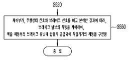
또한, 본 발명의 일 실시예에 따른 작업기계의 제동 방법은, 도 8에 도시된 바와 같이, 단계 S510 및 단계 S520을 수행한 후, 제어부(150)가, 주행상태 신호와 브레이크 신호를 비교 분석한 결과에 따라, 브레이크 밸브(330)의 작동을 제어하여, 액슬 제동부(240)의 브레이크 유닛(241)에 압유가 공급되어 작업기계의 제동을 구현하는 단계(S550)를 더 포함할 수 있다.8, after performing steps S510 and S520, the
상기에서, 주행상태 신호가 전진 신호 또는 후진 신호일 경우, 브레이크 밸브(330)가 작동되면서 액슬 제동부(240)의 브레이크 유닛(241)에 압유가 공급되어 액슬을 압착함에 의해 작업기계의 전진 또는 후진 방향 제동이 이루어질 수 있다.When the running state signal is a forward signal or a backward signal, pressure oil is supplied to the
액슬 제동부(240)에서 작업기계의 제동을 구현하는 단계 S550은 클러치 제동부(140)에서 작업기계의 제동을 구현하는 단계 S530과 동시에 또는 순서에 관계없이 순차적으로 이루어질 수 있다. 작업기계의 제동이 순차적으로 이루어질 경우, 작업기계의 안정적인 제동을 위해 액슬을 직접 제동하는 액슬 제동부(240)가 먼저 작동되도록 하는 액슬 제동방식에 의한 제동이 먼저 이루어지는 것이 바람직할 수 있다.
The step S550 of implementing the braking of the work machine in the
또한, 본 발명의 일 실시예에 따른 작업기계의 제동 방법은, 도 9에 도시된 바와 같이, 브레이크 신호를 입력 받는 단계 S520 전에, 제어부(150)가, 제동 선택부(410)로부터 제동선택 신호를 입력 받는 단계(S515)를 더 포함할 수 있다.9, when the
상기에서, 제동선택 신호는 클러치 제동부(140)에서 작업기계의 제동을 위한 감속 기능이 구현될 수 있게 선택하는 클러치 제동 신호와, 액슬 제동부(240)에서 작업기계의 제동이 구현될 수 있게 선택하는 액슬 제동 신호로 구분될 수 있다.In the above, the braking selection signal is generated by a clutch braking signal that allows the
제어부(150)가, 클러치 제동 신호를 입력 받으면, 단계 S520을 거쳐 단계 S530으로 진행되어 클러치 제동부(140)에서 작업기계의 제동을 위한 감속 기능이 구현될 수 있게 한다.When the
제어부(150)가, 액슬 제동 신호를 입력 받으면, 단계 S520을 거쳐 단계 S540으로 진행되어 액슬 제동부(240)에서 작업기계의 제동이 구현될 수 있게 한다.When the
제어부(150)가, 클러치 제동 신호 및 액슬 제동 신호를 입력 받거나 받지 못하면, 클러치 제동부(140) 및 액슬 제동부(240)에서 작업기계의 제동이 구현될 수 있게 한다.
If the
이와 같이 본 실시예는, 액슬 제동방식과 클러치 제동방식으로 작업기계의 제동이 이루어질 수 있도록 구성함으로써, 작업기계의 제동력이 액슬에 집중되지 않고 클러치에 분산될 수 있어, 액슬 제동방식에 사용되는 기존의 마찰판 개수를 줄일 수 있고, 제동시 마찰로 인한 액슬의 부담을 덜어주어 액슬의 수명 및 액슬 내부 부품의 수명을 증대시킬 수 있고, 발열 감소로 기존의 쿨링 시스템을 삭제 또는 사양 축소를 가능하게 할 수 있고, 작업기계의 원가를 절감할 수 있다.As described above, according to the present embodiment, the braking force of the working machine can be distributed to the clutch without being concentrated on the axle by configuring the braking of the working machine by the axle braking system and the clutch braking system, It is possible to reduce the number of friction plates of the axle and to reduce the load of the axle due to friction during braking to increase the life of the axle and the life of the internal parts of the axle, And the cost of the working machine can be reduced.
또한, 본 실시예는, 클러치 제동방식과 액슬 제동방식 중에서 적어도 어느 하나의 방식을 선택할 수 있도록 구성함으로써, 운전자가 감속의 정도를 선택할 수 있어, 운전자가 느끼는 감성품질에 맞는 맞춤형 제동으로 운전자가 작업기계의 제동 과정에서 느낄 수 있는 불쾌감을 해소할 수 있고, 작업기계의 안전 운행을 확보할 수 있다.In this embodiment, at least one of the clutch braking system and the axle braking system can be selected so that the driver can select the degree of deceleration, and the driver can select the degree of deceleration, The discomfort felt during the braking process of the machine can be solved and the safe operation of the working machine can be ensured.
또한, 본 실시예는, 유압식 트랜스미션을 이용한 클러치 제동방식으로 작업기계의 제동이 이루어질 수 있도록 구성함으로써, 액슬을 압착하는 기존의 브레이크 시스템(액슬 제동방식)의 설치를 생략할 수 있어, 작업기계의 제동시 액슬에 물리적 영향을 끼치지 않아, 액슬의 수명을 연장시킬 수 있고, 액슬의 유지보수 또는 교체에 따른 비용 절감을 이룰 수 있고, 액슬에 쿨링 시스템을 설치하지 않아도 되어 작업기계의 제조 단가의 절감으로 타사와의 경쟁력 우위를 점할 수 있다.In addition, in this embodiment, since the braking of the working machine can be performed by the clutch braking system using the hydraulic transmission, the installation of the existing brake system (axle braking system) for pressing the axle can be omitted, It is possible to prolong the lifetime of the axle, to reduce the cost due to the maintenance or replacement of the axle, to eliminate the need to install a cooling system in the axle, The company will be able to gain competitive edge with other companies.
또한, 본 실시예는, 브레이크 신호의 양에 따라 유압 구동원의 전진 또는 후진 비례제어밸브로부터 출력되는 압유의 양이 조절되면서 작업기계의 제동이 이루어질 수 있도록 구성함으로써, 제동을 위한 감속도의 크기가 선형적으로 이루어질 수 있어, 운전자가 감속의 정도를 임의로 조절할 수 있고, 작업기계의 제동 안정성을 향상시킬 수 있다.
In this embodiment, the amount of pressure oil output from the forward or backward proportional control valve of the hydraulic drive source is controlled according to the amount of the brake signal so that the braking of the working machine can be performed, So that the driver can arbitrarily adjust the degree of deceleration and improve the braking stability of the working machine.
이상 본 발명을 구체적인 실시예를 통하여 상세히 설명하였으나, 이는 본 발명을 구체적으로 설명하기 위한 것으로, 본 발명은 이에 한정되지 않으며, 본 발명의 기술적 사상 내에서 당해 분야의 통상의 지식을 가진 자에 의해 그 변형이나 개량이 가능함은 명백하다고 할 것이다.While the present invention has been particularly shown and described with reference to exemplary embodiments thereof, it is to be understood that the same is by way of illustration and example only and is not to be construed as limiting the present invention. It is obvious that the modification and the modification are possible.
본 발명의 단순한 변형 내지 변경은 모두 본 발명의 영역에 속하는 것으로 본 발명의 구체적인 보호 범위는 첨부된 특허청구범위에 의하여 명확해질 것이다.It will be understood by those skilled in the art that various changes in form and details may be made therein without departing from the spirit and scope of the invention as defined by the appended claims.
10: 엔진 20: 브레이크 페달
100, 200, 300, 400: 브레이크 시스템
110: 브레이크 감지부 120: 주행상태 감지부
130: 유압 구동원 131: 전진 비례제어밸브
132: 후진 비례제어밸브 140: 클러치 제동부
141: 전진 클러치 142: 후진 클러치
230, 330: 브레이크 밸브 240: 액슬 제동부
241: 브레이크 유닛 410: 제동 선택부
411: 클러치 제동 스위치 412: 액슬 제동 스위치10: engine 20: brake pedal
100, 200, 300, 400: Brake system
110: Brake detection unit 120:
130: Hydraulic drive source 131: Forward proportional control valve
132: reverse ratio control valve 140: clutch disengagement portion
141: forward clutch 142: reverse clutch
230, 330: brake valve 240: axle-
241: Brake unit 410: Brake selection unit
411: clutch brake switch 412: axle brake switch
Claims (20)
작업기계의 전진, 후진 또는 정지 상태를 감지하여 주행상태 신호를 출력하는 주행상태 감지부;
유압 구동원으로부터 압유의 공급 여부에 따라 작동 또는 작동 해제되며, 전진 클러치와 후진 클러치를 포함하는 클러치 제동부;
상기 브레이크 페달의 조작에 의해 작동되는 브레이크 밸브; 및
상기 작업기계의 액슬에 설치되며, 상기 브레이크 밸브를 통한 압유의 공급 여부에 따라 작동 또는 작동 해제되는 액슬 제동부를 포함하고,
상기 액슬 제동부의 작동에 의한 액슬 제동방식과 상기 클러치 제동부의 작동에 의한 클러치 제동방식의 조합에 의해 상기 작업기계의 제동이 구현되되, 상기 액슬 제동부와 상기 클러치 제동부가 제동력을 나누어 상기 작업기계의 제동을 위한 감속 기능을 구현하는 것을 특징으로 하는 작업기계의 브레이크 시스템. A brake sensing unit for sensing the depression of the brake pedal and outputting a brake signal;
A running state detecting unit for detecting a forward, backward, or stop state of the work machine and outputting a running state signal;
A clutch braking portion that is operated or deactivated depending on whether or not the pressurized oil is supplied from the hydraulic drive source, the clutch braking portion including a forward clutch and a reverse clutch;
A brake valve operated by operation of the brake pedal; And
And an axle braking portion mounted on an axle of the working machine and operated or released according to whether or not the pressure oil is supplied through the brake valve,
Wherein the braking of the working machine is realized by a combination of an axle braking system by an operation of the axle braking unit and a clutch braking system by an operation of the clutch braking unit, wherein the axle braking unit and the clutch braking unit And a deceleration function for braking the working machine is implemented.
압력 센서 또는 각도 센서로서, 상기 브레이크 페달의 작동을 감지하는 감지 장치를 포함하는 것을 특징으로 하는 작업기계의 브레이크 시스템.The brake control apparatus according to claim 1,
A pressure sensor or angle sensor comprising a sensing device for sensing the actuation of the brake pedal.
상기 주행상태 신호는 전진 신호이고,
상기 후진 클러치에 연결되는 후진 비례제어밸브가 폐쇄 상태에서 개방 상태로 작동되면,
상기 후진 클러치에 의해 증가되는 후진력이 상기 전진 클러치에 의한 전진력과 상충하게 되어 상기 클러치 제동부에서 상기 작업기계의 전진 방향 제동을 위한 감속 기능이 구현되는 것을 특징으로 하는 작업기계의 브레이크 시스템.The method according to claim 1,
The running state signal is a forward signal,
When the reverse proportional control valve connected to the reverse clutch is operated from the closed state to the open state,
And a decelerating function for braking in the forward direction of the working machine is implemented in the clutch braking portion as the backward force increased by the reverse clutch conflicts with the forwarding force by the forward clutch.
상기 주행상태 신호는 후진 신호이고,
상기 전진 클러치에 연결되는 전진 비례제어밸브가 폐쇄 상태에서 개방 상태로 작동되면,
상기 전진 클러치에 의해 증가되는 전진력이 상기 후진 클러치에 의한 후진력과 상충하게 되어 상기 클러치 제동부에서 상기 작업기계의 후진 방향 제동을 위한 감속 기능이 구현되는 것을 특징으로 하는 작업기계의 브레이크 시스템.The method according to claim 1,
The running state signal is a backward signal,
When the forward proportional control valve connected to the forward clutch is operated from the closed state to the open state,
And a decelerating function for braking in the reverse direction of the work machine is implemented in the clutch braking portion as the forward force increased by the forward clutch conflicts with the backward force by the reverse clutch.
상기 주행상태 신호는 전진 신호 또는 후진 신호이고,
상기 브레이크 페달의 조작에 의해 상기 브레이크 밸브가 작동되면,
상기 액슬 제동부의 브레이크 유닛에 압유가 공급되어 액슬을 압착함에 의해 상기 작업기계의 전진 또는 후진 방향 제동이 구현되는 것을 특징으로 하는 작업기계의 브레이크 시스템.The method according to claim 1,
The running state signal is a forward signal or a backward signal,
When the brake pedal is operated by the brake pedal,
And a braking unit for braking the forward or backward direction of the working machine is realized by supplying pressurized oil to the brake unit of the axle braking unit and pressing the axle.
상기 클러치 제동부와 동시에 또는 순차적으로 작동되는 것을 특징으로 하는 작업기계의 브레이크 시스템.The steering apparatus according to claim 1, wherein the axle-
Wherein the brake system is operated simultaneously or sequentially with the clutch braking unit.
운전자의 조작에 의해 상기 클러치 제동부와 상기 액슬 제동부 중에서 적어도 어느 하나가 선택 작동되도록 제동선택 신호를 출력하는 제동 선택부를 더 포함하는 것을 특징으로 하는 작업기계의 브레이크 시스템.The method according to claim 1,
Further comprising a braking selection unit for outputting a braking selection signal so that at least one of the clutch braking unit and the axle braking unit is selectively operated by an operation of the driver.
상기 제동선택 신호는 클러치 제동 신호이고,
상기 클러치 제동 신호, 상기 주행상태 신호, 상기 브레이크 신호를 비교 분석한 결과에 따라, 상기 유압 구동원의 전진 비례제어밸브 또는 후진 비례제어밸브 중에서 폐쇄 상태의 해당 비례제어밸브가 작동되면,
상기 클러치 제동부의 상기 전진 클러치 또는 상기 후진 클러치 중에서 상기 해당 비례제어밸브에 연결되는 해당 클러치에 압유가 공급되어 상기 작업기계의 제동이 구현되는 것을 특징으로 작업기계의 브레이크 시스템.11. The method of claim 10,
The braking selection signal is a clutch braking signal,
When the corresponding proportional control valve in the closed state is operated among the forward proportional control valve or the reverse proportional control valve of the hydraulic drive source according to the result of comparing and analyzing the clutch braking signal, the running state signal and the brake signal,
Wherein pressure oil is supplied to a clutch connected to the proportional control valve among the forward clutch or the reverse clutch of the clutch braking portion so that the braking of the working machine is realized.
상기 제동선택 신호는 액슬 제동 신호이고,
상기 브레이크 밸브가 작동되면,
액슬 제동부의 브레이크 유닛에 압유가 공급되어 액슬을 압착함에 의해 상기 작업기계의 전진 또는 후진 방향 제동이 구현되는 것을 특징으로 하는 작업기계의 브레이크 시스템. 11. The method of claim 10,
The braking selection signal is an axle braking signal,
When the brake valve is operated,
And a braking unit for braking the forward or backward direction of the working machine is realized by supplying pressurized oil to the brake unit of the axle braking unit and pressing the axle.
상기 제동선택 신호는 클러치 제동 신호, 액슬 제동 신호이고,
상기 클러치 제동 신호와 상기 액슬 제동 신호 모두가 입력 되거나, 모두 입력되지 않을 경우,
상기 클러치 제동부 및 상기 액슬 제동부에 의해서 상기 작업기계의 제동이 구현되는 것을 특징으로 하는 작업기계의 브레이크 시스템. 11. The method of claim 10,
Wherein the braking selection signal is a clutch braking signal and an axle braking signal,
When both the clutch braking signal and the axle braking signal are inputted or not inputted,
Wherein the braking of the working machine is realized by the clutch braking unit and the axle braking unit.
상기 제어부가, 브레이크 감지부로부터 브레이크 신호를 입력 받는 단계;
상기 제어부가, 상기 주행상태 신호와 상기 브레이크 신호를 비교 분석한 결과에 따라, 브레이크 밸브의 작동을 제어하여, 액슬 제동부의 브레이크 유닛에 압유가 공급되어 작업기계의 제동이 구현되는 단계; 및
상기 제어부가, 상기 주행상태 신호와 상기 브레이크 신호를 비교 분석한 결과에 따라, 유압 구동원의 전진 비례제어밸브 또는 후진 비례제어밸브 중에서 폐쇄 상태의 해당 비례제어밸브의 작동을 제어하여, 클러치 제동부의 전진 클러치 또는 후진 클러치 중에서 해당 비례제어밸브에 연결되는 해당 클러치에 압유가 공급되어 상기 클러치 제동부에 의한 상기 작업기계의 제동에 더하여 상기 작업기계의 제동이 구현되되, 상기 액슬 제동부와 상기 클러치 제동부가 제동력을 나누어 상기 작업기계의 제동을 위한 감속 기능을 구현하는 단계를 포함하는 것을 특징으로 하는 작업기계의 제동 방법.The control unit receiving the running state signal from the running state detecting unit;
The control unit receiving a brake signal from the brake sensing unit;
Controlling the operation of the brake valve according to a result of comparing and analyzing the running state signal and the brake signal so that braking of the working machine is implemented by supplying pressurized oil to the brake unit of the axle braking unit; And
The control unit controls the operation of the proportional control valve in the closed state among the forward proportional control valve or the reverse proportional control valve of the hydraulic driving source according to the result of comparing and analyzing the traveling state signal and the brake signal, The hydraulic fluid is supplied to the corresponding clutch connected to the proportional control valve among the forward clutch and the reverse clutch so that the braking of the working machine is implemented in addition to the braking of the working machine by the clutch braking portion, And the step of dividing the braking force to implement the deceleration function for braking the working machine.
상기 제어부가, 제동 선택부로부터 제동선택 신호를 입력 받는 단계를 더 포함하는 것을 특징으로 하는 작업기계의 제동 방법. 15. The method of claim 14, further comprising: before receiving the break signal,
Further comprising the step of the controller receiving the brake selection signal from the brake selection unit.
상기 클러치 제동부에서 상기 작업기계의 제동을 위한 감속 기능이 구현될 수 있게 선택하는 클러치 제동 신호; 및
상기 액슬 제동부에서 상기 작업기계의 제동이 구현될 수 있게 선택하는 액슬 제동 신호를 포함하는 것을 특징으로 하는 작업기계의 제동 방법. 19. The method as claimed in claim 18,
A clutch braking signal for enabling the deceleration function for braking the working machine to be implemented in the clutch braking section; And
And an axle braking signal for selecting the braking of the working machine to be implemented in the axle braking section.
상기 제어부가, 상기 클러치 제동 신호를 입력 받으면, 상기 클러치 제동부에서 상기 작업기계의 제동을 위한 감속 기능이 구현될 수 있게 제어하고,
상기 제어부가, 상기 액슬 제동 신호를 입력 받으면, 상기 액슬 제동부에서 상기 작업기계의 제동이 구현될 수 있게 제어하고,
상기 제어부가, 상기 클러치 제동 신호 및 상기 액슬 제동 신호를 입력 받거나 받지 못하면, 상기 클러치 제동부 및 상기 액슬 제동부에서 상기 작업기계의 제동이 구현될 수 있게 제어하는 것을 특징으로 하는 작업기계의 제동 방법.20. The method of claim 19,
Wherein the control unit controls the clutch braking unit to implement a deceleration function for braking the working machine when the clutch braking signal is input,
Wherein the control unit controls the braking of the working machine to be implemented in the axle braking unit when receiving the axle braking signal,
Wherein the control unit controls the braking of the working machine in the clutch braking unit and the axle braking unit when the control unit does not receive or receive the clutch braking signal and the axle braking signal .
Priority Applications (1)
| Application Number | Priority Date | Filing Date | Title |
|---|---|---|---|
| KR1020150051927A KR101959011B1 (en) | 2015-04-13 | 2015-04-13 | Brake system and braking method for working machine |
Applications Claiming Priority (1)
| Application Number | Priority Date | Filing Date | Title |
|---|---|---|---|
| KR1020150051927A KR101959011B1 (en) | 2015-04-13 | 2015-04-13 | Brake system and braking method for working machine |
Publications (2)
| Publication Number | Publication Date |
|---|---|
| KR20160122331A KR20160122331A (en) | 2016-10-24 |
| KR101959011B1 true KR101959011B1 (en) | 2019-03-19 |
Family
ID=57256834
Family Applications (1)
| Application Number | Title | Priority Date | Filing Date |
|---|---|---|---|
| KR1020150051927A Active KR101959011B1 (en) | 2015-04-13 | 2015-04-13 | Brake system and braking method for working machine |
Country Status (1)
| Country | Link |
|---|---|
| KR (1) | KR101959011B1 (en) |
Cited By (1)
| Publication number | Priority date | Publication date | Assignee | Title |
|---|---|---|---|---|
| WO2024058403A1 (en) * | 2022-09-16 | 2024-03-21 | 엘에스엠트론 주식회사 | Agricultural work vehicle and method for controlling same |
Families Citing this family (3)
| Publication number | Priority date | Publication date | Assignee | Title |
|---|---|---|---|---|
| KR102510867B1 (en) | 2018-01-31 | 2023-03-16 | 현대두산인프라코어 주식회사 | Brake contorl apparatus and brake control method for construction machinery |
| KR101914571B1 (en) * | 2018-07-13 | 2018-12-28 | (주)엠에스정밀 | Auto parking system of construction vehicle |
| KR101934989B1 (en) * | 2018-07-13 | 2019-04-05 | (주)엠에스정밀 | Auto holding system of construction vehicle |
Family Cites Families (6)
| Publication number | Priority date | Publication date | Assignee | Title |
|---|---|---|---|---|
| KR101007484B1 (en) | 2005-12-27 | 2011-01-12 | 현대중공업 주식회사 | Safety method for a folklift truck |
| KR20090131356A (en) * | 2008-06-18 | 2009-12-29 | 우영유압주식회사 | Driving control method of vehicle with simple structure transmission |
| KR20090131355A (en) * | 2008-06-18 | 2009-12-29 | 우영유압주식회사 | Driving safety control device of vehicle with simple structure transmission |
| KR101462284B1 (en) | 2008-12-24 | 2014-11-14 | 주식회사 두산 | Safety control system of electric parking brake for electromotive forklift truck and method therefor |
| KR101925588B1 (en) * | 2012-12-10 | 2018-12-05 | 주식회사 두산 | Automatic Brake System of Forklift Truck |
| KR101868169B1 (en) * | 2013-06-20 | 2018-06-15 | 현대건설기계 주식회사 | Electro-hydraulic valve system of excavator |
-
2015
- 2015-04-13 KR KR1020150051927A patent/KR101959011B1/en active Active
Cited By (1)
| Publication number | Priority date | Publication date | Assignee | Title |
|---|---|---|---|---|
| WO2024058403A1 (en) * | 2022-09-16 | 2024-03-21 | 엘에스엠트론 주식회사 | Agricultural work vehicle and method for controlling same |
Also Published As
| Publication number | Publication date |
|---|---|
| KR20160122331A (en) | 2016-10-24 |
Similar Documents
| Publication | Publication Date | Title |
|---|---|---|
| KR101959011B1 (en) | Brake system and braking method for working machine | |
| US7748791B2 (en) | Combination secondary master cylinder and brake pedal compliance device for automotive braking system | |
| KR101970856B1 (en) | Hydraulic control device for work machine | |
| US8321113B2 (en) | Vehicle control device and vehicle mounted with the device | |
| US8376476B2 (en) | Brake system in electric drive dump truck | |
| US8950378B2 (en) | Retarding system | |
| DE112012000056T5 (en) | Forklift and crawl control method of a forklift | |
| KR101931231B1 (en) | Automatic deceleration system for working equipment and method therefor | |
| US20100204872A1 (en) | Vehicle controller and vehicle mounted with the same | |
| JP2001233191A (en) | Vehicle deceleration control device | |
| US9096231B2 (en) | Rollback prevention system for mobile machine | |
| JP2019148278A (en) | Hydraulic system of construction machine | |
| KR102631106B1 (en) | How the brake system works and how the brake system works | |
| US7517300B2 (en) | Retarding system implementing torque converter lockup | |
| US10894536B2 (en) | Service brake actuation using a linear actuator | |
| JP4308852B2 (en) | Control device and control method for input clutch of work vehicle | |
| US20130256052A1 (en) | Rollback prevention system for mobile machine | |
| KR101933222B1 (en) | transmission hydraulic system of forklift | |
| JP2006111196A (en) | Vehicle control device | |
| JP4069795B2 (en) | Hydraulic travel drive device | |
| KR101945518B1 (en) | Parking brake system for working equipment | |
| JP4432832B2 (en) | Industrial vehicle speed control device, industrial vehicle, and industrial vehicle speed control method | |
| RU2860020C2 (en) | Method and system for controlling braking of electrically driven construction machines | |
| KR20140074623A (en) | Method for Deceleration of Forklift Truck | |
| KR101413905B1 (en) | Hydraulic control system of disk brake apparatus for forklift truck |
Legal Events
| Date | Code | Title | Description |
|---|---|---|---|
| PA0109 | Patent application |
St.27 status event code: A-0-1-A10-A12-nap-PA0109 |
|
| PG1501 | Laying open of application |
St.27 status event code: A-1-1-Q10-Q12-nap-PG1501 |
|
| N231 | Notification of change of applicant | ||
| PN2301 | Change of applicant |
St.27 status event code: A-3-3-R10-R13-asn-PN2301 St.27 status event code: A-3-3-R10-R11-asn-PN2301 |
|
| A201 | Request for examination | ||
| PA0201 | Request for examination |
St.27 status event code: A-1-2-D10-D11-exm-PA0201 |
|
| E902 | Notification of reason for refusal | ||
| PE0902 | Notice of grounds for rejection |
St.27 status event code: A-1-2-D10-D21-exm-PE0902 |
|
| AMND | Amendment | ||
| E13-X000 | Pre-grant limitation requested |
St.27 status event code: A-2-3-E10-E13-lim-X000 |
|
| P11-X000 | Amendment of application requested |
St.27 status event code: A-2-2-P10-P11-nap-X000 |
|
| P13-X000 | Application amended |
St.27 status event code: A-2-2-P10-P13-nap-X000 |
|
| P22-X000 | Classification modified |
St.27 status event code: A-2-2-P10-P22-nap-X000 |
|
| E601 | Decision to refuse application | ||
| PE0601 | Decision on rejection of patent |
St.27 status event code: N-2-6-B10-B15-exm-PE0601 |
|
| AMND | Amendment | ||
| P11-X000 | Amendment of application requested |
St.27 status event code: A-2-2-P10-P11-nap-X000 |
|
| P13-X000 | Application amended |
St.27 status event code: A-2-2-P10-P13-nap-X000 |
|
| PX0901 | Re-examination |
St.27 status event code: A-2-3-E10-E12-rex-PX0901 |
|
| PX0701 | Decision of registration after re-examination |
St.27 status event code: A-3-4-F10-F13-rex-PX0701 |
|
| X701 | Decision to grant (after re-examination) | ||
| GRNT | Written decision to grant | ||
| PR0701 | Registration of establishment |
St.27 status event code: A-2-4-F10-F11-exm-PR0701 |
|
| PR1002 | Payment of registration fee |
St.27 status event code: A-2-2-U10-U11-oth-PR1002 Fee payment year number: 1 |
|
| PG1601 | Publication of registration |
St.27 status event code: A-4-4-Q10-Q13-nap-PG1601 |
|
| PN2301 | Change of applicant |
St.27 status event code: A-5-5-R10-R11-asn-PN2301 |
|
| PN2301 | Change of applicant |
St.27 status event code: A-5-5-R10-R14-asn-PN2301 |
|
| PR1001 | Payment of annual fee |
St.27 status event code: A-4-4-U10-U11-oth-PR1001 Fee payment year number: 4 |
|
| PR1001 | Payment of annual fee |
St.27 status event code: A-4-4-U10-U11-oth-PR1001 Fee payment year number: 5 |
|
| R18-X000 | Changes to party contact information recorded |
St.27 status event code: A-5-5-R10-R18-oth-X000 |
|
| R18-X000 | Changes to party contact information recorded |
St.27 status event code: A-5-5-R10-R18-oth-X000 |
|
| PR1001 | Payment of annual fee |
St.27 status event code: A-4-4-U10-U11-oth-PR1001 Fee payment year number: 6 |
|
| PN2301 | Change of applicant |
St.27 status event code: A-5-5-R10-R13-asn-PN2301 St.27 status event code: A-5-5-R10-R11-asn-PN2301 |
|
| R11 | Change to the name of applicant or owner or transfer of ownership requested |
Free format text: ST27 STATUS EVENT CODE: A-5-5-R10-R11-ASN-PN2301 (AS PROVIDED BY THE NATIONAL OFFICE) |
|
| R13 | Change to the name of applicant or owner recorded |
Free format text: ST27 STATUS EVENT CODE: A-5-5-R10-R13-ASN-PN2301 (AS PROVIDED BY THE NATIONAL OFFICE) |
|
| PR1001 | Payment of annual fee |
St.27 status event code: A-4-4-U10-U11-oth-PR1001 Fee payment year number: 7 |
|
| U11 | Full renewal or maintenance fee paid |
Free format text: ST27 STATUS EVENT CODE: A-4-4-U10-U11-OTH-PR1001 (AS PROVIDED BY THE NATIONAL OFFICE) Year of fee payment: 7 |