KR101955751B1 - Construction machine - Google Patents
Construction machine Download PDFInfo
- Publication number
- KR101955751B1 KR101955751B1 KR1020157007768A KR20157007768A KR101955751B1 KR 101955751 B1 KR101955751 B1 KR 101955751B1 KR 1020157007768 A KR1020157007768 A KR 1020157007768A KR 20157007768 A KR20157007768 A KR 20157007768A KR 101955751 B1 KR101955751 B1 KR 101955751B1
- Authority
- KR
- South Korea
- Prior art keywords
- hydraulic
- motor
- control valve
- directional control
- valve
- Prior art date
- Legal status (The legal status is an assumption and is not a legal conclusion. Google has not performed a legal analysis and makes no representation as to the accuracy of the status listed.)
- Expired - Fee Related
Links
Images


Classifications
-
- F—MECHANICAL ENGINEERING; LIGHTING; HEATING; WEAPONS; BLASTING
- F15—FLUID-PRESSURE ACTUATORS; HYDRAULICS OR PNEUMATICS IN GENERAL
- F15B—SYSTEMS ACTING BY MEANS OF FLUIDS IN GENERAL; FLUID-PRESSURE ACTUATORS, e.g. SERVOMOTORS; DETAILS OF FLUID-PRESSURE SYSTEMS, NOT OTHERWISE PROVIDED FOR
- F15B11/00—Servomotor systems without provision for follow-up action; Circuits therefor
- F15B11/02—Systems essentially incorporating special features for controlling the speed or actuating force of an output member
- F15B11/04—Systems essentially incorporating special features for controlling the speed or actuating force of an output member for controlling the speed
-
- E—FIXED CONSTRUCTIONS
- E02—HYDRAULIC ENGINEERING; FOUNDATIONS; SOIL SHIFTING
- E02F—DREDGING; SOIL-SHIFTING
- E02F9/00—Component parts of dredgers or soil-shifting machines, not restricted to one of the kinds covered by groups E02F3/00 - E02F7/00
- E02F9/08—Superstructures; Supports for superstructures
- E02F9/10—Supports for movable superstructures mounted on travelling or walking gears or on other superstructures
- E02F9/12—Slewing or traversing gears
- E02F9/121—Turntables, i.e. structure rotatable about 360°
- E02F9/123—Drives or control devices specially adapted therefor
-
- E—FIXED CONSTRUCTIONS
- E02—HYDRAULIC ENGINEERING; FOUNDATIONS; SOIL SHIFTING
- E02F—DREDGING; SOIL-SHIFTING
- E02F9/00—Component parts of dredgers or soil-shifting machines, not restricted to one of the kinds covered by groups E02F3/00 - E02F7/00
- E02F9/20—Drives; Control devices
-
- E—FIXED CONSTRUCTIONS
- E02—HYDRAULIC ENGINEERING; FOUNDATIONS; SOIL SHIFTING
- E02F—DREDGING; SOIL-SHIFTING
- E02F9/00—Component parts of dredgers or soil-shifting machines, not restricted to one of the kinds covered by groups E02F3/00 - E02F7/00
- E02F9/20—Drives; Control devices
- E02F9/2025—Particular purposes of control systems not otherwise provided for
- E02F9/2037—Coordinating the movements of the implement and of the frame
-
- E—FIXED CONSTRUCTIONS
- E02—HYDRAULIC ENGINEERING; FOUNDATIONS; SOIL SHIFTING
- E02F—DREDGING; SOIL-SHIFTING
- E02F9/00—Component parts of dredgers or soil-shifting machines, not restricted to one of the kinds covered by groups E02F3/00 - E02F7/00
- E02F9/20—Drives; Control devices
- E02F9/2058—Electric or electro-mechanical or mechanical control devices of vehicle sub-units
- E02F9/2095—Control of electric, electro-mechanical or mechanical equipment not otherwise provided for, e.g. ventilators, electro-driven fans
-
- E—FIXED CONSTRUCTIONS
- E02—HYDRAULIC ENGINEERING; FOUNDATIONS; SOIL SHIFTING
- E02F—DREDGING; SOIL-SHIFTING
- E02F9/00—Component parts of dredgers or soil-shifting machines, not restricted to one of the kinds covered by groups E02F3/00 - E02F7/00
- E02F9/20—Drives; Control devices
- E02F9/22—Hydraulic or pneumatic drives
- E02F9/2203—Arrangements for controlling the attitude of actuators, e.g. speed, floating function
-
- E—FIXED CONSTRUCTIONS
- E02—HYDRAULIC ENGINEERING; FOUNDATIONS; SOIL SHIFTING
- E02F—DREDGING; SOIL-SHIFTING
- E02F9/00—Component parts of dredgers or soil-shifting machines, not restricted to one of the kinds covered by groups E02F3/00 - E02F7/00
- E02F9/20—Drives; Control devices
- E02F9/22—Hydraulic or pneumatic drives
- E02F9/2217—Hydraulic or pneumatic drives with energy recovery arrangements, e.g. using accumulators, flywheels
-
- E—FIXED CONSTRUCTIONS
- E02—HYDRAULIC ENGINEERING; FOUNDATIONS; SOIL SHIFTING
- E02F—DREDGING; SOIL-SHIFTING
- E02F9/00—Component parts of dredgers or soil-shifting machines, not restricted to one of the kinds covered by groups E02F3/00 - E02F7/00
- E02F9/20—Drives; Control devices
- E02F9/22—Hydraulic or pneumatic drives
- E02F9/2278—Hydraulic circuits
- E02F9/2282—Systems using center bypass type changeover valves
-
- E—FIXED CONSTRUCTIONS
- E02—HYDRAULIC ENGINEERING; FOUNDATIONS; SOIL SHIFTING
- E02F—DREDGING; SOIL-SHIFTING
- E02F9/00—Component parts of dredgers or soil-shifting machines, not restricted to one of the kinds covered by groups E02F3/00 - E02F7/00
- E02F9/20—Drives; Control devices
- E02F9/22—Hydraulic or pneumatic drives
- E02F9/2278—Hydraulic circuits
- E02F9/2285—Pilot-operated systems
-
- E—FIXED CONSTRUCTIONS
- E02—HYDRAULIC ENGINEERING; FOUNDATIONS; SOIL SHIFTING
- E02F—DREDGING; SOIL-SHIFTING
- E02F9/00—Component parts of dredgers or soil-shifting machines, not restricted to one of the kinds covered by groups E02F3/00 - E02F7/00
- E02F9/20—Drives; Control devices
- E02F9/22—Hydraulic or pneumatic drives
- E02F9/2278—Hydraulic circuits
- E02F9/2296—Systems with a variable displacement pump
-
- F—MECHANICAL ENGINEERING; LIGHTING; HEATING; WEAPONS; BLASTING
- F15—FLUID-PRESSURE ACTUATORS; HYDRAULICS OR PNEUMATICS IN GENERAL
- F15B—SYSTEMS ACTING BY MEANS OF FLUIDS IN GENERAL; FLUID-PRESSURE ACTUATORS, e.g. SERVOMOTORS; DETAILS OF FLUID-PRESSURE SYSTEMS, NOT OTHERWISE PROVIDED FOR
- F15B11/00—Servomotor systems without provision for follow-up action; Circuits therefor
- F15B11/02—Systems essentially incorporating special features for controlling the speed or actuating force of an output member
- F15B11/028—Systems essentially incorporating special features for controlling the speed or actuating force of an output member for controlling the actuating force
-
- F—MECHANICAL ENGINEERING; LIGHTING; HEATING; WEAPONS; BLASTING
- F15—FLUID-PRESSURE ACTUATORS; HYDRAULICS OR PNEUMATICS IN GENERAL
- F15B—SYSTEMS ACTING BY MEANS OF FLUIDS IN GENERAL; FLUID-PRESSURE ACTUATORS, e.g. SERVOMOTORS; DETAILS OF FLUID-PRESSURE SYSTEMS, NOT OTHERWISE PROVIDED FOR
- F15B11/00—Servomotor systems without provision for follow-up action; Circuits therefor
- F15B11/16—Servomotor systems without provision for follow-up action; Circuits therefor with two or more servomotors
- F15B11/161—Servomotor systems without provision for follow-up action; Circuits therefor with two or more servomotors with sensing of servomotor demand or load
- F15B11/162—Servomotor systems without provision for follow-up action; Circuits therefor with two or more servomotors with sensing of servomotor demand or load for giving priority to particular servomotors or users
-
- F—MECHANICAL ENGINEERING; LIGHTING; HEATING; WEAPONS; BLASTING
- F15—FLUID-PRESSURE ACTUATORS; HYDRAULICS OR PNEUMATICS IN GENERAL
- F15B—SYSTEMS ACTING BY MEANS OF FLUIDS IN GENERAL; FLUID-PRESSURE ACTUATORS, e.g. SERVOMOTORS; DETAILS OF FLUID-PRESSURE SYSTEMS, NOT OTHERWISE PROVIDED FOR
- F15B11/00—Servomotor systems without provision for follow-up action; Circuits therefor
- F15B11/16—Servomotor systems without provision for follow-up action; Circuits therefor with two or more servomotors
- F15B11/161—Servomotor systems without provision for follow-up action; Circuits therefor with two or more servomotors with sensing of servomotor demand or load
- F15B11/165—Servomotor systems without provision for follow-up action; Circuits therefor with two or more servomotors with sensing of servomotor demand or load for adjusting the pump output or bypass in response to demand
-
- F—MECHANICAL ENGINEERING; LIGHTING; HEATING; WEAPONS; BLASTING
- F15—FLUID-PRESSURE ACTUATORS; HYDRAULICS OR PNEUMATICS IN GENERAL
- F15B—SYSTEMS ACTING BY MEANS OF FLUIDS IN GENERAL; FLUID-PRESSURE ACTUATORS, e.g. SERVOMOTORS; DETAILS OF FLUID-PRESSURE SYSTEMS, NOT OTHERWISE PROVIDED FOR
- F15B13/00—Details of servomotor systems ; Valves for servomotor systems
- F15B13/02—Fluid distribution or supply devices characterised by their adaptation to the control of servomotors
- F15B13/06—Fluid distribution or supply devices characterised by their adaptation to the control of servomotors for use with two or more servomotors
-
- F—MECHANICAL ENGINEERING; LIGHTING; HEATING; WEAPONS; BLASTING
- F15—FLUID-PRESSURE ACTUATORS; HYDRAULICS OR PNEUMATICS IN GENERAL
- F15B—SYSTEMS ACTING BY MEANS OF FLUIDS IN GENERAL; FLUID-PRESSURE ACTUATORS, e.g. SERVOMOTORS; DETAILS OF FLUID-PRESSURE SYSTEMS, NOT OTHERWISE PROVIDED FOR
- F15B13/00—Details of servomotor systems ; Valves for servomotor systems
- F15B13/14—Special measures for giving the operating person a "feeling" of the response of the actuated device
-
- F—MECHANICAL ENGINEERING; LIGHTING; HEATING; WEAPONS; BLASTING
- F16—ENGINEERING ELEMENTS AND UNITS; GENERAL MEASURES FOR PRODUCING AND MAINTAINING EFFECTIVE FUNCTIONING OF MACHINES OR INSTALLATIONS; THERMAL INSULATION IN GENERAL
- F16H—GEARING
- F16H61/00—Control functions within control units of change-speed- or reversing-gearings for conveying rotary motion ; Control of exclusively fluid gearing, friction gearing, gearings with endless flexible members or other particular types of gearing
- F16H61/38—Control of exclusively fluid gearing
- F16H61/40—Control of exclusively fluid gearing hydrostatic
- F16H61/4078—Fluid exchange between hydrostatic circuits and external sources or consumers
-
- F—MECHANICAL ENGINEERING; LIGHTING; HEATING; WEAPONS; BLASTING
- F15—FLUID-PRESSURE ACTUATORS; HYDRAULICS OR PNEUMATICS IN GENERAL
- F15B—SYSTEMS ACTING BY MEANS OF FLUIDS IN GENERAL; FLUID-PRESSURE ACTUATORS, e.g. SERVOMOTORS; DETAILS OF FLUID-PRESSURE SYSTEMS, NOT OTHERWISE PROVIDED FOR
- F15B15/00—Fluid-actuated devices for displacing a member from one position to another; Gearing associated therewith
- F15B15/20—Other details, e.g. assembly with regulating devices
- F15B2015/206—Combined actuation, e.g. electric and fluid actuated
-
- F—MECHANICAL ENGINEERING; LIGHTING; HEATING; WEAPONS; BLASTING
- F15—FLUID-PRESSURE ACTUATORS; HYDRAULICS OR PNEUMATICS IN GENERAL
- F15B—SYSTEMS ACTING BY MEANS OF FLUIDS IN GENERAL; FLUID-PRESSURE ACTUATORS, e.g. SERVOMOTORS; DETAILS OF FLUID-PRESSURE SYSTEMS, NOT OTHERWISE PROVIDED FOR
- F15B2211/00—Circuits for servomotor systems
- F15B2211/20—Fluid pressure source, e.g. accumulator or variable axial piston pump
- F15B2211/205—Systems with pumps
- F15B2211/20507—Type of prime mover
- F15B2211/20515—Electric motor
-
- F—MECHANICAL ENGINEERING; LIGHTING; HEATING; WEAPONS; BLASTING
- F15—FLUID-PRESSURE ACTUATORS; HYDRAULICS OR PNEUMATICS IN GENERAL
- F15B—SYSTEMS ACTING BY MEANS OF FLUIDS IN GENERAL; FLUID-PRESSURE ACTUATORS, e.g. SERVOMOTORS; DETAILS OF FLUID-PRESSURE SYSTEMS, NOT OTHERWISE PROVIDED FOR
- F15B2211/00—Circuits for servomotor systems
- F15B2211/70—Output members, e.g. hydraulic motors or cylinders or control therefor
- F15B2211/705—Output members, e.g. hydraulic motors or cylinders or control therefor characterised by the type of output members or actuators
- F15B2211/7058—Rotary output members
-
- F—MECHANICAL ENGINEERING; LIGHTING; HEATING; WEAPONS; BLASTING
- F15—FLUID-PRESSURE ACTUATORS; HYDRAULICS OR PNEUMATICS IN GENERAL
- F15B—SYSTEMS ACTING BY MEANS OF FLUIDS IN GENERAL; FLUID-PRESSURE ACTUATORS, e.g. SERVOMOTORS; DETAILS OF FLUID-PRESSURE SYSTEMS, NOT OTHERWISE PROVIDED FOR
- F15B2211/00—Circuits for servomotor systems
- F15B2211/70—Output members, e.g. hydraulic motors or cylinders or control therefor
- F15B2211/71—Multiple output members, e.g. multiple hydraulic motors or cylinders
- F15B2211/7135—Combinations of output members of different types, e.g. single-acting cylinders with rotary motors
-
- F—MECHANICAL ENGINEERING; LIGHTING; HEATING; WEAPONS; BLASTING
- F15—FLUID-PRESSURE ACTUATORS; HYDRAULICS OR PNEUMATICS IN GENERAL
- F15B—SYSTEMS ACTING BY MEANS OF FLUIDS IN GENERAL; FLUID-PRESSURE ACTUATORS, e.g. SERVOMOTORS; DETAILS OF FLUID-PRESSURE SYSTEMS, NOT OTHERWISE PROVIDED FOR
- F15B2211/00—Circuits for servomotor systems
- F15B2211/70—Output members, e.g. hydraulic motors or cylinders or control therefor
- F15B2211/75—Control of speed of the output member
-
- F—MECHANICAL ENGINEERING; LIGHTING; HEATING; WEAPONS; BLASTING
- F15—FLUID-PRESSURE ACTUATORS; HYDRAULICS OR PNEUMATICS IN GENERAL
- F15B—SYSTEMS ACTING BY MEANS OF FLUIDS IN GENERAL; FLUID-PRESSURE ACTUATORS, e.g. SERVOMOTORS; DETAILS OF FLUID-PRESSURE SYSTEMS, NOT OTHERWISE PROVIDED FOR
- F15B2211/00—Circuits for servomotor systems
- F15B2211/70—Output members, e.g. hydraulic motors or cylinders or control therefor
- F15B2211/78—Control of multiple output members
- F15B2211/781—Control of multiple output members one or more output members having priority
Landscapes
- Engineering & Computer Science (AREA)
- General Engineering & Computer Science (AREA)
- Mining & Mineral Resources (AREA)
- Civil Engineering (AREA)
- Structural Engineering (AREA)
- Mechanical Engineering (AREA)
- Physics & Mathematics (AREA)
- Fluid Mechanics (AREA)
- Operation Control Of Excavators (AREA)
- Fluid-Pressure Circuits (AREA)
Abstract
선회체(50)와, 유압 펌프(1)와, 유압 펌프(1)로부터의 작동유로 선회체(50)를 구동하는 유압 모터(3)와, 유압 모터(3)와 함께 또는 단독으로, 선회체(50)를 구동하는 전동 모터(14)와, 선회체(50)와 동시에 동작하는 경우가 있고, 유압 펌프(1)로부터의 작동유에 의해 구동되는 유압 액추에이터(16)를 구비하고, 선회체(50)와 유압 액추에이터(16)를 동시에 동작시킬 때에는, 전동 모터(14)만으로 선회체(50)를 선회시킨다.A hydraulic motor 3 that drives the rotating body 50 with working oil from the hydraulic pump 1 and a hydraulic motor 3 which is connected to the hydraulic motor 3 alone or in combination with a rotary And a hydraulic actuator 16 driven by the hydraulic oil from the hydraulic pump 1. The hydraulic actuator 16 is driven by the hydraulic oil from the hydraulic pump 1, The turning body 50 is turned only by the electric motor 14 when operating the hydraulic actuator 50 and the hydraulic actuator 16 at the same time.
Description
본 발명은 선회체의 구동원으로서 유압 모터와 전동 모터의 양쪽을 구비하는 건설 기계에 관한 것이다.The present invention relates to a construction machine having both a hydraulic motor and an electric motor as a drive source of a turning body.
엔진에 의해 구동되는 유압 펌프와, 당해 유압 펌프로부터의 작동유에 의해 구동되는 유압 액추에이터와, 선회체를 구비하는 건설 기계(예를 들어, 유압 셔블)에는 전동 모터로 선회체의 구동과 제동을 행하여, 선회 제동 시의 선회체의 운동 에너지를 전기 에너지로 회생하는 하이브리드식의 것이 있다. 당해 건설 기계에서는 선회 제동 시에 얻은 회생 전력을 이용하여 전동 모터로 선회체를 구동함으로써, 유압 펌프 동력(즉, 엔진 부하)을 내리고, 엔진의 연료 소비량의 삭감에 의한 에너지 절약화를 도모하고 있다.BACKGROUND ART [0002] A construction machine (for example, a hydraulic excavator) provided with a hydraulic pump driven by an engine, a hydraulic actuator driven by hydraulic oil from the hydraulic pump, and a revolving body is driven and braked by an electric motor , And a hybrid type in which kinetic energy of the revolving body at the time of braking is regenerated into electric energy. In the construction machine, the revolving body is driven by the electric motor using the regenerative power obtained during the braking of the revolving motion, thereby reducing the hydraulic pump power (that is, the engine load) and saving energy by reducing the fuel consumption of the engine .
이러한 종류의 하이브리드식 건설 기계에는 선회체를 선회하기 위한 모터(선회 모터)로서 유압 모터와 전동 모터의 양쪽을 탑재한 것(유압 전동 복합 선회)이 있다(예를 들어, 일본 특허 출원 공개 제2011-241653호 공보). 이 건설 기계에서는, 통상, 유압 선회 모터와, 다른 유압 액추에이터(유압 실린더)를 동일한 유압 회로 상에 배치하여, 동일한 유압 펌프로 퍼 올린 압유를 갖고 각각을 구동하게 되므로, 이 점에 대해서는 유압 모터 단독으로 선회체를 구동하는 종래형의 건설 기계와 동일한 구성으로 된다.This type of hybrid type construction machine has a hydraulic motor and an electric motor both mounted as a motor (swing motor) for turning the swing structure (hydraulically-powered complex turn) (see, for example, Japanese Patent Application Laid- -241653). In this construction machine, normally, the hydraulic swing motor and the other hydraulic actuator (hydraulic cylinder) are disposed on the same hydraulic circuit, and each of them is driven by the hydraulic oil pumped by the same hydraulic pump. The same construction as that of the conventional construction machine for driving the rotating body is realized.
상기와 같이 유압 선회 모터와 다른 유압 액추에이터가 동일한 유압 펌프로부터 압유의 공급을 받는 시스템에 있어서, 당해 유압 선회 모터와 당해 다른 유압 액추에이터가 오퍼레이터에 의해 동시에 조작된 경우에는, 상대적으로 부하가 작은 액추에이터에 보다 많은 작동유가 흐른다. 그로 인해, 유압 선회 모터의 부하가 상대적으로 작은 경우에는, 유압 선회 모터에 작동유가 보다 많이 흘러 선회체가 가속하여, 오퍼레이터의 조작 필링이 저하되는 경우가 있다. 특히, 상기와 같이 유압 선회 모터와 전동 선회 모터의 양쪽에서 선회체를 구동하는 경우에는, 종래형의 건설 기계보다도 유압 선회 모터의 부하가 작아지는 경향이 있으므로, 유압 선회 모터에 의해 작동유가 흐르기 쉬워진다.In the system in which the hydraulic swing motor and other hydraulic actuators are supplied with the pressurized oil from the same hydraulic pump as described above, when the hydraulic swing motor and the other hydraulic actuator are simultaneously operated by the operator, More hydraulic fluid flows. As a result, when the load of the hydraulic swing motor is relatively small, the hydraulic fluid is more likely to flow to the hydraulic swing motor, causing the swing body to accelerate, resulting in a decrease in the operation feeling of the operator. In particular, when the swivel body is driven by both the hydraulic swivel motor and the electric swivel motor as described above, the load of the hydraulic swivel motor tends to be smaller than that of the conventional type construction machine. Therefore, the hydraulic oil is easily flowed by the hydraulic swivel motor Loses.
예를 들어, 상기와 같이 유압 선회 모터와 다른 유압 액추에이터가 동일한 유압 펌프로부터 작동유의 공급을 받는 시스템에는, 당해 다른 유압 액추에이터로서 유압 셔블에 있어서의 붐 실린더를 배치한 것이 있다. 이 시스템에 있어서, 선회 조작 중에 붐 상승 조작(선회 붐 상승 조작)을 실행한 경우이며, 유압 선회 모터보다도 상대적으로 큰 부하가 붐 실린더에 작용하는 경우(예를 들어, 저속 선회 중에 현수 화물을 들어올리는 동작을 행한 경우)에는, 붐 상승 조작의 개시에 의해 유압 펌프압이 상승하고, 고압의 작동유가 부하가 가벼운 유압 선회 모터에 유입되어(압입되어) 선회체를 가속시키는 경우가 있다. 예를 들어, 저속 선회하면서 소정의 목표 위치까지 현수 화물을 정확하게 이동시키려고 하고 있는 경우에, 또한 붐 상승 조작을 함으로써 상기와 같은 선회체의 가속이 발생하면, 선회체가 가속하지 않는 통상의 경우와 다른 동작을 하게 되어, 오퍼레이터가 당해 목표 위치에서 현수 화물을 정확하게 정지하는 것이 어려워진다.For example, in a system in which the hydraulic swivel motor and the other hydraulic actuator receive the supply of hydraulic oil from the same hydraulic pump as described above, a boom cylinder in the hydraulic excavator is disposed as the other hydraulic actuator. In this system, when the boom raising operation (turning boom raising operation) is performed during the swing operation and a load relatively larger than the hydraulic swing motor is applied to the boom cylinder (for example, The hydraulic pump pressure is increased by the start of the boom raising operation, and the high-pressure hydraulic oil may flow into the light hydraulic swing motor (press-in) the load to accelerate the swing body. For example, when acceleration of the swing structure is generated by the boom raising operation when the suspension is to be accurately moved to a predetermined target position while rotating at a low speed, the swing structure is not accelerated So that it becomes difficult for the operator to accurately stop the suspension cargo at the target position.
본 발명의 목적은 선회체의 구동원으로서 유압 모터와 전동 모터를 구비하는 건설 기계에 있어서, 선회 복합 동작 시의 오퍼레이터의 조작 필링을 양호하게 유지할 수 있는 것을 제공하는 데 있다.SUMMARY OF THE INVENTION It is an object of the present invention to provide a construction machine having a hydraulic motor and an electric motor as a drive source of a revolving structure, in which operation peeling of an operator in a turning complex operation can be satisfactorily maintained.
(1) 본 발명은 상기 목적을 달성하기 위해, 선회체와, 유압 펌프와, 당해 유압 펌프로부터의 작동유로 상기 선회체를 구동하는 유압 모터와, 당해 유압 선회 모터와 함께 또는 단독으로, 상기 선회체를 구동하는 전동 모터와, 상기 선회체와 동시에 동작하는 경우가 있고, 상기 유압 펌프로부터의 작동유에 의해 구동되는 유압 액추에이터를 구비하고, 상기 선회체는 상기 유압 액추에이터와 동시에 동작할 때, 상기 전동 모터만으로 선회되는 것으로 한다.(1) In order to achieve the above-described object, the present invention provides a hydraulic control apparatus for a vehicle, comprising a revolving body, a hydraulic pump, a hydraulic motor for driving the revolving body with hydraulic oil from the hydraulic pump, And a hydraulic actuator that is operated by the hydraulic oil from the hydraulic pump when it is operated simultaneously with the hydraulic actuator, wherein when the hydraulic actuator is operated simultaneously with the hydraulic actuator, the electric motor It is assumed that it is turned only by the motor.
(2) 상기 (1)에 있어서, 바람직하게는 상기 선회체와 상기 유압 액추에이터가 동시에 동작할 때, 상기 유압 모터는 상기 유압 펌프로부터의 작동유의 공급이 차단되는 것으로 한다.(2) In (1), it is preferable that when the swivel body and the hydraulic actuator operate simultaneously, the hydraulic motor is cut off the supply of the hydraulic oil from the hydraulic pump.
(3) 상기 (2)에 있어서, 바람직하게는 상기 유압 펌프와 상기 유압 모터를 접속하는 유로에 설치되어, 상기 유압 펌프로부터 상기 유압 모터에 공급되는 작동유의 방향 및 유량을 제어하기 위한 방향 제어 밸브와, 상기 유압 펌프와 상기 방향 제어 밸브를 접속하는 유로에 설치된 개폐 밸브를 더 구비하고, 상기 개폐 밸브는 상기 선회체와 상기 유압 액추에이터가 동시에 동작할 때에 폐쇄 위치로 전환되는 것으로 한다.(3) In the above-mentioned (2), preferably, a direction control valve for controlling the direction and the flow rate of the hydraulic oil supplied from the hydraulic pump to the hydraulic motor is provided in a passage connecting the hydraulic pump and the hydraulic motor, And an opening / closing valve provided in a flow path connecting the hydraulic pump and the directional control valve, wherein the opening / closing valve is switched to a closed position when the rotating body and the hydraulic actuator simultaneously operate.
(4) 상기 (2)에 있어서, 바람직하게는 상기 유압 펌프와 상기 유압 모터를 접속하는 유로에 설치되어, 상기 유압 펌프로부터 상기 유압 모터에 공급되는 작동유의 방향 및 유량을 제어하기 위한 방향 제어 밸브와, 상기 방향 제어 밸브와 상기 유압 모터를 접속하는 유로에 설치된 개폐 밸브를 더 구비하고, 상기 개폐 밸브는 상기 선회체와 상기 유압 액추에이터가 동시에 동작할 때에 폐쇄 위치로 전환되는 것으로 한다.(4) In the above-mentioned (2), preferably, a direction control valve for controlling the direction and the flow rate of the hydraulic oil supplied from the hydraulic pump to the hydraulic motor is provided in a passage connecting the hydraulic pump and the hydraulic motor, And an open / close valve provided in a flow passage connecting the directional control valve and the hydraulic motor, wherein the open / close valve is switched to a closed position when the rotating body and the hydraulic actuator simultaneously operate.
(5) 상기 (2)에 있어서, 바람직하게는 상기 유압 펌프와 상기 유압 모터를 접속하는 유로에 설치되어, 상기 유압 펌프로부터 상기 유압 모터에 공급되는 작동유의 방향 및 유량을 제어하기 위한 방향 제어 밸브와, 상기 선회체와 상기 유압 액추에이터가 동시에 동작할 때, 상기 방향 제어 밸브에 작용하는 제어 신호를 차단하는 차단 장치를 더 구비하는 것으로 한다.(5) In the above-mentioned (2), preferably, a direction control valve for controlling the direction and the flow rate of the hydraulic oil supplied from the hydraulic pump to the hydraulic motor is provided in a passage connecting the hydraulic pump and the hydraulic motor, And a blocking device for blocking a control signal acting on the directional control valve when the rotating body and the hydraulic actuator operate simultaneously.
본 발명에 따르면, 선회체의 구동원으로서 유압 모터와 전동 모터를 구비하는 건설 기계에 있어서, 선회 복합 동작 시의 오퍼레이터의 조작 필링을 양호하게 유지할 수 있다.According to the present invention, in the construction machine having the hydraulic motor and the electric motor as the drive source of the turning body, it is possible to maintain the operation peeling of the operator in the turning complex operation well.
도 1은 본 발명의 실시 형태에 관한 하이브리드식 유압 셔블의 측면도.
도 2는 본 발명의 제1 실시 형태에 관한 유압 시스템(100)의 개략 구성도.
도 3은 본 발명의 비교예에 관한 유압 셔블에 있어서의 유압 시스템의 개략 구성도.
도 4는 본 발명의 제2 실시 형태에 관한 유압 시스템(100A)의 개략 구성도.
도 5는 본 발명의 제3 실시 형태에 관한 유압 시스템(100B)의 개략 구성도.
도 6은 본 발명의 제4 실시 형태에 관한 유압 시스템(100C)의 개략 구성도.
도 7은 본 발명의 제5 실시 형태에 관한 유압 시스템(100D)의 개략 구성도.1 is a side view of a hybrid hydraulic excavator according to an embodiment of the present invention.
2 is a schematic structural view of a
3 is a schematic configuration view of a hydraulic system in a hydraulic excavator according to a comparative example of the present invention.
4 is a schematic structural view of a
5 is a schematic structural view of a
6 is a schematic structural view of a hydraulic system 100C according to a fourth embodiment of the present invention.
7 is a schematic structural view of a hydraulic system 100D according to a fifth embodiment of the present invention.
이하, 건설 기계로서 유압 셔블을 예로 들어, 본 발명에 관한 각 실시 형태에 대해 도면을 사용하여 설명한다. 또한, 본 발명은 상부 선회체와, 당해 선회체의 구동원으로서 유압 선회 모터 및 전동 선회 모터의 양쪽을 구비한 건설 기계 전반에 적용이 가능하고, 본 발명의 적용처는 이하의 설명에 사용하는 크롤러식 유압 셔블로 한정되지 않는다. 예를 들어, 휠식의 유압 셔블이나 크레인을 비롯한 다른 건설 기계에도 적용 가능하다.Hereinafter, each embodiment of the present invention will be described using the drawings as an example of a hydraulic excavator as a construction machine. The present invention is also applicable to a general construction machine having both an upper revolving structure and a hydraulic revolving motor and an electric revolving motor as driving sources of the revolving structure, and the application of the present invention is not limited to the crawler type It is not limited to a hydraulic excavator. For example, it can be applied to other construction machines including wheel-type hydraulic excavators and cranes.
도 1은 본 발명의 실시 형태에 관한 하이브리드식 유압 셔블의 측면도이다. 이 도면에 도시하는 하이브리드식 유압 셔블은 하부 주행체(40)와, 상부 선회체(50)와, 프론트 작업 장치(60)를 구비하고 있다.1 is a side view of a hybrid hydraulic excavator according to an embodiment of the present invention. The hybrid type hydraulic excavator shown in this figure is provided with a lower traveling
하부 주행체(40)는 한 쌍의 크롤러(41a, 41b) 및 크롤러 프레임(45a, 45b)(도 1에서는 편측만을 나타냄), 각 크롤러(41a, 41b)를 독립하여 구동 제어하는 한 쌍의 주행용 유압 모터(46, 47) 및 그 감속 기구를 구비하고 있다.The
상부 선회체(50)는 원동기로서의 엔진(51)과, 어시스트 발전 모터(52)와, 유압 펌프(1)(도 2 참조)와, 유압 선회 모터(3)와, 전동 선회 모터(14)와, 축전 장치(54)와, 감속 기구(59)와, 이들 장치가 탑재되는 선회 프레임(58)을 구비하고 있다.The
어시스트 발전 모터(52)는 엔진(51)에 기계적으로 연결되어 있고, 축전 장치(54)에 전력이 잔존하고 있는 경우에는 엔진(51)을 어시스트하고, 전력이 잔존하고 있지 않은 경우에는 엔진(51)에 의해 구동되어 발전을 행한다. 유압 펌프(1)는 엔진(51)에 기계적으로 연결되어 있고, 탱크(4)(도 2 참조) 내의 작동유를 퍼 올려 각 유압 액추에이터에 작동유를 공급한다.The assist
유압 선회 모터(3) 및 전동 선회 모터(14)는 모두 상부 선회체(50)의 구동원이고, 감속 기구(59)를 통해 상부 선회체(50)를 선회 구동한다. 유압 선회 모터(3)는 유압 펌프(1)로부터의 작동유로 상부 선회체(50)를 선회 구동한다. 전동 선회 모터(14)는 축전 장치(54) 또는 어시스트 발전 모터(52)로부터의 전력에 의해 상부 선회체(50)를 선회 구동한다. 상부 선회체(50)의 구동원으로서 유압 모터(3) 및 전동 모터(14)를 어떻게 사용할지[예를 들어, 유압 모터(3)와 전동 모터(14)의 양쪽 또는 어느 한쪽을 사용할지]는, 다른 유압 액추에이터의 동작 상태나 축전 장치(54)의 축전 잔량 등에 따라서 적절히 변경된다. 전동 선회 모터(14)와 유압 선회 모터(3)의 구동력은 감속 기구(59)를 통해 전달되고, 그 구동력에 의해 하부 주행체(40)에 대해 상부 선회체(50)[선회 프레임(58)]가 선회 구동된다.The
축전 장치(54)는 어시스트 발전 모터(52) 및 전동 선회 모터(14)로의 급전과, 이들 모터(52, 14)가 발생한 전력의 축전을 행한다. 축전 장치(54)로서는, 예를 들어 전기 이중층 캐패시터가 이용 가능하다.The
상부 선회체(50)의 전방 부분에는 프론트 작업 장치(셔블 기구)(60)가 설치되어 있다. 프론트 작업 장치(60)는 붐(61)과, 붐(61)을 구동하기 위한 붐 실린더(16)와, 붐(61)의 선단 부분에 회전 가능하게 설치된 아암(63)과, 아암(63)을 구동하기 위한 아암 실린더(62)와, 아암(63)의 선단 부분에 회전 가능하게 설치된 버킷(65)과, 버킷(65)을 구동하기 위한 버킷 실린더(66)를 구비하고 있다.A front working device (shovel mechanism) 60 is provided at a front portion of the upper revolving
상부 선회체(50)의 선회 프레임(58) 상에는 상술한 주행용 유압 모터(46, 47), 유압 선회 모터(3), 붐 실린더(16), 아암 실린더(62), 버킷 실린더(66) 등의 유압 액추에이터를 구동하기 위한 유압 시스템(100)이 탑재되어 있다.The
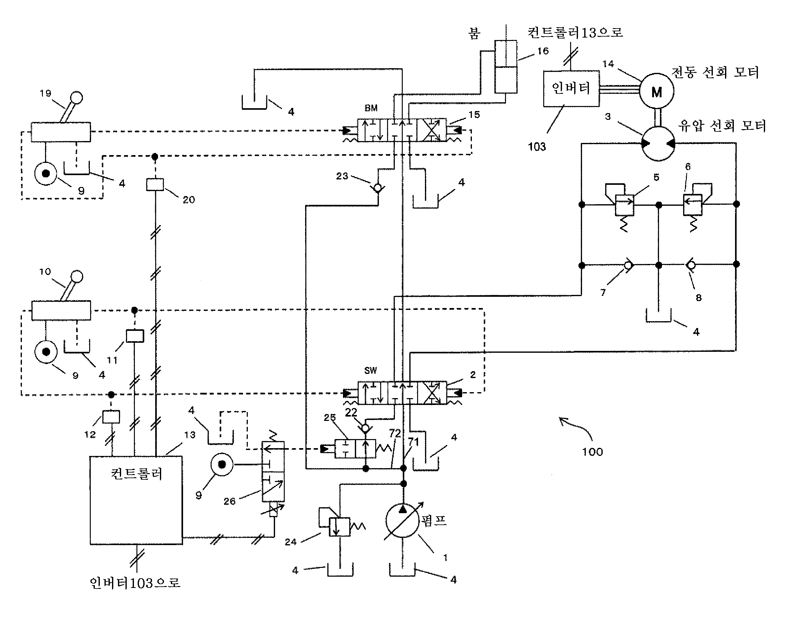
도 2는 본 발명의 제1 실시 형태에 관한 오픈 센터 방식의 유압 시스템(100)의 개략 구성도이다. 여기서는, 상부 선회체(50)와 동시에 동작하는 유압 액추에이터는 붐 실린더(16)로 한다. 또한, 대상 동작으로서는, 아암과 버킷의 결합부의 근방에 설치된 훅 등을 통해 행해지는 「현수 화물 작업」을 상정하여 설명한다. 그로 인해, 도 1에 도시한 유압 셔블에 탑재된 각 유압 액추에이터를 제어하기 위한 방향 제어 밸브(컨트롤 밸브)는 유압 선회 모터(14)와 붐 실린더(16)를 제어하는 것[방향 제어 밸브(2, 15)]만을 도시하고 있다. 또한, 앞의 도면과 동일한 부분에는 동일한 부호를 부여하여 설명을 생략하는 경우가 있다(뒤의 도면에 대해서도 마찬가지임).2 is a schematic configuration diagram of an open center type
이 도면에 도시하는 시스템은 유압 선회 모터(3)에 공급되는 작동유의 방향 및 유량을 제어하기 위한 방향 제어 밸브(컨트롤 밸브)(2)와, 붐 실린더(16)에 공급되는 작동유의 방향 및 유량을 제어하기 위한 방향 제어 밸브(컨트롤 밸브)(15)와, 개폐 밸브(25)와, 전자기 전환 밸브(26)와, 상부 선회체(50)의 선회 동작을 조작하기 위해 유압 조작 신호(파일럿압)를 출력하는 조작 레버(조작 장치)(10)와, 붐(61)의 회전 동작[붐 실린더(16)의 신축 동작]을 조작하기 위한 유압 조작 신호(파일럿압)를 출력하는 조작 레버(조작 장치)(19)와, 전동 선회 모터(14) 및 전자기 전환 밸브(26) 등의 제어를 포함하는 유압 셔블 전반에 관한 제어를 행하는 컨트롤러(제어 장치)(13)와, 컨트롤러(13)로부터 출력되는 제어 신호에 기초하여 전동 선회 모터(14)를 제어하기 위한 인버터 장치(전력 변환 장치)(103)와, 릴리프 밸브(24)를 구비하고 있다.The system shown in this figure includes a directional control valve (control valve) 2 for controlling the direction and the flow rate of the hydraulic oil supplied to the
유압 펌프(1)로부터 토출된 작동유가 흐르는 유로는 센터 바이패스 유로(71)와, 센터 바이패스 유로(71)에 병렬로 접속된 미터 인 유로(72)에 접속되어 있다.The flow path through which the hydraulic fluid discharged from the
센터 바이패스 유로(71)는, 우선 방향 제어 밸브(2)를 통과하고, 다음에 방향 제어 밸브(15)를 통과하여, 탱크(4)로 복귀된다. 즉, 센터 바이패스 유로(71)는 2개의 방향 제어 밸브(2, 15)를 직렬로 접속하고 있다.The
미터 인 유로(72)는 유압 펌프(1)로부터 토출된 작동유를 방향 제어 밸브(2, 15)를 통해 각 유압 액추에이터[유압 선회 모터(3) 및 붐 실린더(16)]에 도입하는 것이고, 본 실시 형태에서는 2개의 방향 제어 밸브(2, 15)(2개의 유압 액추에이터)를 병렬로 접속하고 있다.The hydraulic
미터 인 유로(72)가 방향 제어 밸브(2)와 방향 제어 밸브(15)에 접속되기 직전에는 체크 밸브(22, 23)가 각각 설치되어 있다. 체크 밸브(22, 23)는 유압 펌프(1)의 토출압(펌프압)이 액추에이터(3, 16)측의 압력(액추에이터압)보다도 높은 경우에만, 유압 선회 모터(3) 및 붐 실린더(16)에 작동유를 공급한다.
상부 선회체(50)와 붐(61)을 천천히 움직일 때[즉, 조작 레버(10, 19)의 경도량이 비교적 작을 때]를 비교하면, 선회에 의한 펌프 부하는 붐 상승에 의한 펌프 부하보다 작다. 그로 인해, 2개의 방향 제어 밸브(2, 15)에 있어서의 센터 바이패스 스로틀의 개구 면적에 대해서는, 붐 상승 시의 펌프압을 보다 높게 할 수 있도록 붐 실린더(16)에 관한 방향 제어 밸브(15)의 쪽이 상대적으로 작게 설정되어 있다(교축량이 상대적으로 큼).When the
릴리프 밸브(24)는 센터 바이패스 유로(71)와 미터 인 유로(72)에 대해 병렬로 접속되어 있고, 펌프압이 릴리프압에 도달했을 때에 작동유를 탱크(4)에 릴리프시킨다.The
조작 레버(10)에는 엔진(51)에 의해 구동되는 파일럿 펌프(도시하지 않음)가 토출된 압유가 도입되어 있다. 당해 파일럿 펌프로부터의 압유는 도 2 중의 유압원(9)으로부터 도입된다. 조작 레버(10)는 그 경도량에 따라서 유압원(9)으로부터의 압유를 감압하면서, 그 경도 방향에 따른 유로에 파일럿압을 생성한다. 조작 레버(10)로 생성된 파일럿압은 방향 제어 밸브(2)의 스풀에 작용하여 방향 제어 밸브(2)의 전환 위치를 적절히 전환한다.A pressure oil discharged from a pilot pump (not shown) driven by the
조작 레버(10)가 출력한 파일럿압은 압력 센서(11) 또는 압력 센서(12)에 의해 검출되어, 컨트롤러(13)에 출력된다.The pilot pressure outputted by the
방향 제어 밸브(2)는 미터 인 유로(72)를 통해 도입되는 작동유를 유압 선회 모터(3)로 공급한다. 유압 선회 모터(3)에 대한 작동유의 공급 방향은 방향 제어 밸브(2)의 전환 위치에 따라서 적절히 선택된다. 유압 선회 모터(3)로부터의 복귀유는 방향 제어 밸브(2)를 통해 탱크(4)로 복귀된다.The
유압 선회 모터(3)에 관한 유압 회로에는 유압 선회 모터(3)에 작동유가 흐르는 방향에 대응시켜 2개의 릴리프 밸브(5, 6)와, 2개의 메이크업 밸브(7, 8)가 설치되어 있다. 릴리프 밸브(5, 6)는 릴리프압까지 도달한 작동유를 탱크(4)에 릴리프시키기 위한 것으로, 선회의 가감속 시 등에 발생하는 이상압을 차단하여 회로를 보호하는 기능을 갖는다. 메이크업 밸브(7, 8)는 유로의 작동유가 부족하여 그 압력이 탱크압보다도 낮아졌을 때에, 탱크(4)로부터 작동유를 흡입하기 위한 것이다. 1조의 릴리프 밸브(5, 6)의 하류측과, 1조의 메이크업 밸브(7, 8)의 상류측은 탱크(4)에 통하는 유로에 접속되어 있다.Two
유압 선회 모터(3)에는 전동 선회 모터(14)가 동축 상에 접속되어 있고, 전동 선회 모터(14)의 구동 및 제동은 인버터 장치(103)에 의해 제어되어 있다. 선회 단독 동작 시[다른 액추에이터는 정지시키고 선회체(50)만을 동작시킬 때]에는, 상부 선회체(50)는 유압 선회 모터(3)와 전동 선회 모터(14)의 복합력에 의해 구동된다. 또한, 전동 선회 모터(14)와 유압 선회 모터(3)는 공통의 구동 대상인 상부 선회체(50)를 구동 가능한 구성이면 기계적 기구 등을 통해 간접적으로 접속해도 된다.The
조작 레버(19)에는 조작 레버(10)와 마찬가지로, 파일럿 펌프로부터의 압유가 유압원(9)으로부터 도입되어 있다. 조작 레버(19)는 그 경도량에 따라서 유압원(9)으로부터의 압유를 감압하면서, 그 경도 방향에 따른 유로에 파일럿압을 생성한다. 조작 레버(19)로 생성된 파일럿압은 방향 제어 밸브(15)의 스풀에 작용하여 방향 제어 밸브(15)의 전환 위치를 적절히 전환한다.As in the case of the
조작 레버(19)로 붐(61)의 인상 조작[붐 실린더(16)의 신장 동작]을 실행한 경우에 파일럿압이 발생하는 유로에는 압력 센서(20)가 설치되어 있다. 압력 센서(20)에 의해 검출된 파일럿압은 컨트롤러(13)에 출력된다.A
방향 제어 밸브(15)는 미터 인 유로(72)를 통해 도입되는 작동유를 붐 실린더(16)로 공급한다. 붐 실린더(16)에 대한 작동유의 공급 방향은 방향 제어 밸브(15)의 전환 위치에 따라서 적절히 선택된다. 예를 들어, 조작 레버(19)를 붐 상승 방향으로 조작하면, 방향 제어 밸브(15)의 스풀이 도면 중 좌측 방향으로 이동하여, 붐 실린더(16)에 있어서의 보톰측 유압실에 펌프(1)로부터 작동유가 공급된다. 붐 실린더(16)로부터의 복귀유는 방향 제어 밸브(15)를 통해 탱크(4)로 복귀된다.The
개폐 밸브(25)는 유압 파일럿식 밸브이고, 유압 펌프(1)와 방향 제어 밸브(2)를 접속하는 미터 인 유로(72)에 있어서의 체크 밸브(22)의 상류측에 설치되어 있다. 개폐 밸브(25)가 폐쇄 위치(후술)로 전환되면, 미터 인 유로(72)로부터 방향 제어 밸브(2)로의 작동유의 공급이 차단되므로, 방향 제어 밸브(2)의 하류측에 설치되는 유압 선회 모터(3)로의 작동유의 공급도 차단된다.The on / off
전자기 전환 밸브(26)는 개폐 밸브(25)를 조작하는 파일럿압을 발생하는 것으로, 컨트롤러(13)로부터 출력되는 전기 신호에 의해 제어된다. 컨트롤러(13)로부터 전기 신호의 입력이 없는 경우에는, 전자기 전환 밸브(26)는 도 2에 도시한 위치(OFF 위치)로 전환되어 있고, 개폐 밸브(25)로의 파일럿압은 탱크압으로 유지되어 있다. 이때 개폐 밸브(25)는 도 2에 도시한 개방 위치에 보유 지지된다. 한편, 컨트롤러(13)로부터 전기 신호의 입력이 있었던 경우에는, 전자기 전환 밸브(26)가 도 2에 있어서의 상방(ON 위치)으로 이동하고, 전자기 전환 밸브(26)는 유압원(9)을 통해 파일럿 펌프로부터 출력되는 파일럿압을 개폐 밸브(25)에 작용시킨다. 이에 의해 개폐 밸브(25)는 도 2에 있어서의 우측으로 이동하여 폐쇄 위치로 전환된다.The
컨트롤러(13)는 조작 레버(10)에 의한 선회 조작과 조작 레버(19)에 의한 붐 상승 조작이 동시에 행해졌는지 여부를 판정하여, 당해 판정 처리에 있어서 양 조작이 동시에 행해졌다고 판정된 경우에 전자기 전환 밸브(26)에 전기 신호를 출력하는 처리를 실행한다. 상술한 바와 같이, 컨트롤러(13)는 선회 조작의 유무를 압력 센서(11, 12)의 출력값에 의해 판정하고 있고, 붐 상승 조작의 유무를 압력 센서(20)의 출력값에 의해 판정하고 있다. 조작의 유무의 판정 방법으로서는, 예를 들어 조작 레버(10, 19)가 오퍼레이터에게 조작된 경우에 발생하는 파일럿압의 최솟값에 상당하는 출력값을 역치(예를 들어, 1.0㎫)로 하고, 각 센서(11, 12, 20)로부터의 출력값이 당해 역치 이상에 도달했는지 여부에 의해 조작의 유무를 판정하는 것이 있다.The
컨트롤러(13)는 오퍼레이터에 의해 선회 조작과 붐 상승 조작이 동시에 행해졌다고 판정한 경우, 전기 신호를 출력함으로써 전자기 밸브(26)를 ON 위치로 전환하고, 개폐 밸브(25)를 폐쇄 위치로 전환한다. 이에 의해 유압 펌프(1)로부터의 작동유는 방향 제어 밸브(2)에 도착하기 전에 개폐 밸브(25)에 의해 차단된다. 그 결과, 상부 선회체(50)는 붐(61)의 상승[붐 실린더(16)의 신장]과 함께, 전동 선회 모터(14)만으로 선회된다. 한편, 선회 붐 상승 조작이 행해지지 않았다고 판정한 경우에는, 전자기 밸브(26)는 OFF 위치에 보유 지지되고, 개폐 밸브(25)는 개방 위치에 보유 지지된다. 이에 의해, 유압 펌프(1)로부터의 작동유는 미터 인 유로(72)로부터 방향 제어 밸브(2)를 통해 유압 선회 모터(3)에 도입될 수 있다.When it is determined by the operator that the turning operation and the boom raising operation are performed at the same time, the
또한, 컨트롤러(13)는 선회 복합 동작의 유무에 관계없이 조작 레버(10)의 조작 방향 및 조작량[즉, 압력 센서(11, 12)의 출력값]에 따라서 상부 선회체(50)가 선회하도록, 인버터 장치(103)가 전동 선회 모터(14)를 제어하기 위한 제어 신호를 생성하고, 당해 제어 신호를 인버터 장치(103)에 출력하는 처리도 행하고 있다. 컨트롤러(13)로부터 출력된 제어 신호에 기초하여 인버터 장치(103)는 전동 선회 모터(14)를 제어한다. 컨트롤러(13) 및 인버터 장치(103)에 의한 전동 선회 모터(14)의 제어는 공지의 방법을 이용하면 된다. 예를 들어, 조작 레버의 조작량으로부터 결정되는 목표 속도에 상부 선회체(50)의 속도가 가까워지도록, 유압 모터(3)의 부족 토크분을 보충하기 위해 전동 모터(14)를 피드백 제어하는 것이나, 조작 레버(10)의 조작량으로부터 산출되는 목표 토크가 전동 모터(14)와 유압 모터(3)로부터 출력되도록 양자의 토크를 적절히 분배하는 것 등이 있다. 본 실시 형태에서는, 선회 복합 동작 시에는 유압 선회 모터(3)는 토크를 출력하지 않는다. 그로 인해, 당해 부족분의 토크를 전동 선회 모터(14)로 보충하도록 제어함으로써, 유압 모터 단독으로 선회체를 구동하는 종래의 유압 회로에 있어서의 조작 필링과, 유압 모터(3) 및 전동 모터(14)에 의해 선회체(50)를 구동하는 본 실시 형태의 유압 회로 및 제어에 의한 조작 필링에 변화가 생기지 않도록 할 수 있다.The
여기서, 본 발명이 발휘하는 효과의 이해를 용이하게 하기 위해, 종래형의 유압 셔블에 대해 설명한다. 도 2에 도시한 시스템이 오픈 센터 방식이므로, 여기서도 오픈 센터 방식의 것을 이용하여 설명한다. 오픈 센터 방식의 유압 시스템에 있어서의 방향 제어 밸브는 탱크에 통하는 센터 바이패스 개구와, 액추에이터로 공급되는 작동유가 통하는 미터 인 개구와, 액추에이터로부터 복귀되어 온 작동유가 통하는 미터 아웃 개구를 구비하고 있다.Here, in order to facilitate understanding of the effect of the present invention, a conventional hydraulic excavator will be described. Since the system shown in Fig. 2 is an open center system, an open center system will be described here as well. The directional control valve in the open center type hydraulic system is provided with a center bypass opening to the tank, a meter opening through which the operating oil supplied to the actuator passes, and a meter-out opening through which the operating oil returned from the actuator passes.
조작 레버를 조작하여 중립 위치에 있는 방향 제어 밸브를 이동시키면 미터 인 개구가 개방되어, 액추에이터에 압유를 유입할 수 있다. 또한, 방향 제어 밸브를 이동시키면 미터 아웃 개구가 개방되어, 액추에이터로부터의 복귀유를 탱크로 복귀시킬 수 있다.When the directional control valve in the neutral position is moved by operating the operating lever, the meter-like opening is opened, and the pressurized oil can flow into the actuator. Further, when the directional control valve is moved, the meter-out opening is opened, and return oil from the actuator can be returned to the tank.
또한, 중립 위치에 있는 방향 제어 밸브를 이동시키면 센터 바이패스 개구가 교축된다. 이에 의해 센터 바이패스 개구의 통과 전후에 있어서의 작동유의 차압이 커져, 유압 펌프의 토출압이 상승한다. 펌프압이 유압 액추에이터의 구동에 필요한 압력(액추에이터 부하)을 초과하여 상승하면, 유압 펌프로부터의 압유가 당해 액추에이터에 유입되어 당해 액추에이터가 구동한다. 또한, 센터 바이패스 개구 면적은 유압 펌프로부터의 압유가 액추에이터에 유입될 때에, 유압 액추에이터와 센터 바이패스로 분류하는 작동유의 비율을 결정하므로, 액추에이터의 동작 속도도 제어한다.Also, moving the directional control valve in the neutral position deflects the center bypass opening. As a result, the differential pressure of the hydraulic oil before and after passing through the center bypass opening increases, and the discharge pressure of the hydraulic pump increases. When the pump pressure rises above the pressure required for driving the hydraulic actuator (actuator load), the pressure oil from the hydraulic pump flows into the actuator, and the actuator is driven. Further, the center bypass opening area also controls the operating speed of the actuator since the ratio of the hydraulic actuator and the hydraulic oil classified by the center bypass is determined when the pressure oil from the hydraulic pump flows into the actuator.
상기와 같이 방향 제어 밸브의 센터 바이패스 개구는 구동 대상의 액추에이터에 작용하는 부하의 정도나, 조작 레버의 조작량(파일럿압)에 대한 액추에이터 속도에 따라서 최적으로 설정되어 있다.As described above, the center bypass opening of the directional control valve is optimally set in accordance with the degree of the load acting on the actuator to be driven and the actuator speed with respect to the operation amount of the operation lever (pilot pressure).
예를 들어, 선회에 관한 방향 제어 밸브의 센터 바이패스 개구는 다음과 같이 설정되어 있다. 오퍼레이터가 선회에 관한 조작 레버를 약간만 경도한 경우, 오퍼레이터는 저속도에서의 선회를 요구하고 있게 된다. 또한, 유압 셔블의 상부 선회체를 천천히 선회(등속 선회)시키기 위해 필요한 부하는 높지는 않다. 그로 인해, 이 경우에는 펌프압을 상승시킬 필요성이 낮으므로, 선회에 관한 방향 제어 밸브의 센터 바이패스 개구는 비교적 크게 설정된다.For example, the center bypass opening of the directional control valve for turning is set as follows. When the operator slightly hardens the operating lever for turning, the operator is requesting turning at a low speed. In addition, the load required for slowly turning the upper revolving body of the hydraulic excavator (uniform speed turning) is not high. Therefore, in this case, since the necessity of raising the pump pressure is low, the center bypass opening of the directional control valve with respect to the turning is set to be relatively large.
또한, 예를 들어 붐 상승에 관한 방향 제어 밸브의 센터 바이패스 개구는 다음과 같이 설정되어 있다. 오퍼레이터가 조작 레버를 약간만 경도한 경우, 오퍼레이터는 저속도에서의 붐 상승을 요구하고 있게 된다. 그러나, 현수 작업 시에는 버킷에 부하가 가해지므로 붐 부하가 높고, 붐을 구동하기 위해서는 펌프압을 상승시킬 필요성이 높다. 그로 인해, 붐 실린더에 작동유를 공급하기 위해, 붐 상승의 센터 바이패스 개구는 비교적 작게 설정된다.Further, for example, the center bypass opening of the directional control valve with respect to the boom lift is set as follows. When the operator slightly hardens the operation lever, the operator is required to raise the boom at a low speed. However, during the suspension operation, a load is applied to the bucket, so that the boom load is high. In order to drive the boom, it is highly necessary to increase the pump pressure. Thereby, in order to supply the operating oil to the boom cylinder, the center bypass opening of the boom rise is set to be relatively small.
이와 같이, 동일한 레버 조작량이라도, 조작 대상의 액추에이터의 부하나 속도에 따라서는, 조작성과 효율을 양립하는 최적의 센터 바이패스 개구가 다르다. 또한, 일반적으로, 유압 셔블 등에 탑재되는 유압 시스템에서는 1개의 유압 펌프로부터의 토출되는 작동유는 복수의 유압 액추에이터를 구동하기 위해 방향 제어 밸브에 의해 적절히 분류되도록 되어 있다. 상기의 오픈 센터 방식에서는, 각 방향 제어 밸브의 센터 바이패스 라인은 직렬로 접속되어 있고, 복수의 액추에이터의 센터 바이패스 개구의 합성이, 펌프압과, 액추에이터측으로 유입되는 유량을 결정하고 있다.Thus, even in the case of the same lever manipulated variable, the optimum center bypass opening that achieves operability and efficiency differs depending on the speed or the speed of the actuator to be operated. In general, in a hydraulic system mounted on a hydraulic excavator or the like, the hydraulic fluid discharged from one hydraulic pump is appropriately classified by a directional control valve to drive a plurality of hydraulic actuators. In the open center system described above, the center bypass lines of the directional control valves are connected in series, and the combination of the center bypass openings of the plurality of actuators determines the pump pressure and the flow rate to be introduced into the actuator side.
도 3은 본 발명의 비교예에 관한 유압 셔블에 있어서의 유압 시스템의 개략 구성도이다. 이 도면에 도시하는 유압 시스템은, 도 2에 도시한 유압 시스템(100)으로부터 개폐 밸브(25)와 전자기 전환 밸브(26)를 생략한 것에 상당한다. 본 실시 형태와 달리, 선회 붐 상승 시에는, 상부 선회체(50)는 유압 선회 모터(3)와 전동 선회 모터(14)에 의해 구동된다.3 is a schematic configuration diagram of a hydraulic system in a hydraulic excavator according to a comparative example of the present invention. The hydraulic system shown in this figure corresponds to the
이 도면에 도시한 오픈 센터 방식의 유압 시스템과 같이, 선회의 제어에 관한 방향 제어 밸브(2)와 붐의 제어에 관한 방향 제어 밸브(15)가 동일 라인에 배치되어 있으면, 다음과 같은 현상이 발생한다. 여기서는 당해 현상에 대해 현수 화물 작업을 상정하여 설명한다.If the
우선, 오퍼레이터가 붐 상승 단독 조작에 의해 천천히 화물을 들어올리려고 한 것으로 한다. 붐에 관한 방향 제어 밸브(15)의 센터 바이패스 개구는 높은 부하에서도 붐 실린더(16)에 압유를 공급할 수 있도록 폐쇄하고 있으므로, 붐 실린더(16)가 신장하고 화물은 들어올려진다. 원하는 높이까지 화물이 올라가면, 오퍼레이터는 붐 상승 조작을 정지한다.First, it is assumed that the operator intends to slowly lift the cargo by boom-up single operation. The center bypass opening of the
다음에, 오퍼레이터는 선회 단독 조작에 의해 천천히 화물을 이동시키려고 한 것으로 한다. 화물을 현수하고 있어도 선회의 부하로서는 높지는 않으므로, 선회에 관한 방향 제어 밸브(2)의 센터 바이패스 개구는, 붐에 관한 방향 제어 밸브(15)의 센터 바이패스 개구에 비해 개방되어 있고, 선회체(50)는 천천히 선회한다. 즉, 현수 화물 작업 시, 선회와 붐 각각의 단독 동작에서는, 방향 제어 밸브(2)와 방향 제어 밸브(15)의 센터 바이패스 스로틀은 적절한 스로틀로 되어 있으므로, 펌프압 및 유압 액추에이터(16, 3)로 유입되는 유량은 문제없이 제어된다.Next, it is assumed that the operator intends to slowly move the cargo by turning operation alone. The center bypass opening of the
이에 대해, 선회 중에 화물을 비스듬히 상방향으로 이동시키기 위해, 선회 단독 조작을 하고 있는 상태로부터, 붐 상승 조작을 행하여 복합 동작(선회 붐 상승 동작)을 시킨 것으로 한다. 이때, 선회의 방향 제어 밸브(2)와 붐의 방향 제어 밸브(15)는 동일 펌프 라인에 배치되어 있으므로, 붐 상승 조작에 의해 폐쇄된 센터 바이패스 개구는 선회의 센터 바이패스 개구로서도 기능한다. 즉, 선회의 센터 바이패스가 폐쇄된 상태로 되어, 센터 바이패스 유량과 선회 미터 인 유량의 밸런스가 변화된다. 또한, 붐 상승 부하는 선회 부하보다도 크기 때문에, 선회측의 회로에 압유가 유입되기 쉬운 상태로 되어, 오퍼레이터의 의도에 반하여 유압 선회 모터(3)에 압유가 유입되어 선회가 가속되는 경우가 있다. 현수 화물 이동 중에, 조작에 반하여 선회가 가속되어 버리는 것은, 화물이 흔들려 버리는 원인이 되어 바람직한 것은 아니다.On the contrary, in order to move the cargo in the upward direction at an angle during the turning, the boom is raised from the state where the turning operation is performed alone to perform the combined operation (the turning boom raising operation). At this time, since the turn
이와 같은 과제에 대해, 상기와 같이 구성된 본 실시 형태에 관한 유압 셔블에 의하면, 선회 붐 상승 시에 펌프압이 상승했다고 해도, 유압 선회 모터(3)로의 작동유의 유입이 개폐 밸브(25)에 의해 저지되므로, 오퍼레이터의 의도에 반하여 선회 속도가 가속하는 사태가 발생하는 것을 방지할 수 있다. 따라서, 선회 복합 동작의 유무에 의해 오퍼레이터의 조작 필링이 다른 경우가 없어지므로, 주로 저속 선회 시에 버킷(65)을 목표 위치에 정지시키는 것이 용이해진다.With respect to such a problem, according to the hydraulic excavator of the present embodiment configured as described above, even when the pump pressure rises at the time of the rise of the orbiting boom, the inflow of the hydraulic oil to the
그런데, 본 실시 형태에서는, 선회 붐 상승 조작 시에 있어서의 상부 선회체(50)의 선회는 전동 선회 모터(14) 단독으로 행하고, 유압 선회 모터(3)에 의한 구동은 행해지지 않는다. 그로 인해, 유압 선회 모터(3)는 전동 선회 모터(14)에 의해 회전되게 된다. 이때, 유압 선회 모터(3)의 입구측으로의 작동유의 흡입은 2개의 메이크업 밸브(7, 8) 중 어느 한쪽을 통해 탱크(4)로부터 행해지고, 유압 선회 모터(3)의 출구측으로부터의 작동유의 토출은 방향 제어 밸브(2)를 통해 탱크(4)에 토출된다.However, in the present embodiment, the upper revolving
도 4는 본 발명의 제2 실시 형태에 관한 유압 시스템(100A)의 개략 구성도이다. 본 실시 형태에서는 유압 선회 모터(3)로의 작동유의 유입을 차단하는 수단으로서, 방향 제어 밸브(2)와 유압 선회 모터(3)를 접속하는 2개의 유로에 전자기 개폐 밸브(28, 29)가 설치되어 있다. 또한, 도시한 전자기 밸브(28, 29)는 유압 선회 모터(3)의 상류측이며, 또한 메이크업 밸브(7, 8) 및 릴리프 밸브(5, 6)의 상류측에 설치되어 있다.4 is a schematic configuration diagram of the
전자기 밸브(28, 29)는 컨트롤러(13)로부터 출력되는 전기 신호에 기초하여 제어된다. 컨트롤러(13)로부터의 전기 신호의 입력이 없는 경우에는, 전자기 전환 밸브(28, 29)는 도 4에 도시한 위치[OFF 위치(개방 위치)]로 전환되어, 방향 제어 밸브(2)와 유압 모터(3)의 연통이 보유 지지된다. 한편, 컨트롤러(13)로부터 전기 신호의 입력이 있었던 경우에는, 전자기 전환 밸브(28, 29)가 도 4에 있어서의 상방[ON 위치(폐쇄 위치)]으로 이동하여, 방향 제어 밸브(2)로부터의 유로를 차단함과 함께 유압 선회 모터(3)로부터의 유로를 탱크(4)와 연통한다. 이에 의해 전자기 밸브(28, 29)는 유압 펌프(1)로부터 유압 모터(3)로의 작동유의 공급을 차단한다. 또한, 그때, 전동 모터(14)에 회전되는 유압 모터(3)에 의한 오일의 흡입은 선회 메이크업 밸브[8(7)], 또는 유압 펌프(1)로부터의 압유를 차단하고 있는 전자기 밸브[28(29)]를 통해 행해진다.The
상기와 같이 구성되는 유압 시스템(100A)에 있어서, 컨트롤러(13)는 오퍼레이터에 의해 선회 붐 상승 조작이 행해졌다고 판정한 경우에는, 전기 신호를 출력함으로써 전자기 밸브(28, 29)를 ON 위치로 전환한다. 이에 의해 유압 펌프(1)로부터의 작동유는 유압 모터(3)에 도착하기 전에 전자기 밸브(28) 또는 전자기 밸브(29)에 의해 차단된다. 한편, 선회 붐 상승 조작이 행해지지 않았다고 판정한 경우에는, 컨트롤러(13)는 전기 신호를 전자기 밸브(28, 29)에 출력하지 않으므로, 전자기 밸브(28, 29)는 OFF 위치에 보유 지지된다. 이에 의해, 유압 펌프(1)로부터의 작동유는 미터 인 유로(72)로부터 방향 제어 밸브(2)를 통해 유압 선회 모터(3)에 도입될 수 있다.In the
이와 같이 구성한 실시 형태에 있어서도, 선회 붐 상승 시에 펌프압이 높아졌다고 해도, 그 압유는 유압 모터(3)로는 유입되지 않으므로, 제1 실시 형태와 동일한 효과를 얻을 수 있다.Even in the embodiment having such a configuration, even if the pump pressure increases at the time of the rise of the turning boom, the pressure oil does not flow into the
또한, 상기에서는 선회 붐 상승 시에 2개의 전자기 밸브(28, 29)를 ON 위치로 전환하는 경우에 대해 설명하였지만, 당해 2개의 전자기 밸브(28, 29) 중 조작 레버(10)에 의한 선회 지시 방향에 대응하는 한쪽의 전자기 밸브만을 ON 위치로 전환하는 것뿐이어도 된다. 이 경우에는, 유압 모터(3)로부터의 복귀유는 OFF 위치에 있는 다른 쪽의 전자기 밸브와 방향 제어 밸브(2)를 통해 탱크(4)로 복귀되기 때문이다. 예를 들어, 압력 센서(11)의 검출값이 상승하는 방향으로 조작 레버(10)가 조작된 경우에는, 전자기 밸브(28)를 향해 작동유가 공급되게 되므로, 전자기 밸브(28)만을 ON 위치로 전환하고, 전자기 밸브(29)는 OFF 위치의 상태로 보유 지지해도 된다.In the above description, the two
도 5는 본 발명의 제3 실시 형태에 관한 유압 시스템(100B)의 개략 구성도이다. 본 실시 형태에서는 방향 제어 밸브(2)에 작용하는 파일럿압(제어 신호)을 차단하는 장치(차단 장치)로서 전자기 개폐 밸브(30, 31)를 구비하고 있고, 선회 붐 상승 시에는 당해 전자기 밸브(30, 31)에 의해 유압 선회 모터(3)로의 작동유의 유입을 차단하고 있다.5 is a schematic configuration diagram of a
전자기 밸브(30, 31)는 컨트롤러(13)로부터 출력되는 전기 신호에 기초하여 제어된다. 컨트롤러(13)로부터의 전기 신호의 입력이 없는 경우에는, 전자기 밸브(30, 31)는 도 5에 도시한 위치[OFF 위치(개방 위치)]로 전환되어, 조작 레버(10)에 의해 생성되는 파일럿압이 방향 제어 밸브(2)에 작용 가능하게 되어 있다. 한편, 컨트롤러(13)로부터 전기 신호의 입력이 있었던 경우에는, 전자기 밸브(30, 31)가 도 5에 있어서의 상방[ON 위치(폐쇄 위치)]으로 이동하여, 조작 레버(10)에 의해 생성되는 파일럿압이 방향 제어 밸브(2)에 작용하는 것이 차단된다. 이에 의해 방향 제어 밸브(2)는 중립 위치에 보유 지지되므로, 유압 펌프(1)로부터 유압 모터(3)로의 작동유의 공급은 차단된다.The
상기와 같이 구성되는 유압 시스템(100B)에 있어서, 컨트롤러(13)는 오퍼레이터에 의해 선회 붐 상승 조작이 행해졌다고 판정한 경우에는, 전기 신호를 출력함으로써 4개의 전자기 밸브(28, 29, 30, 31)를 ON 위치로 전환한다. 이 중 2개의 전자기 밸브(30, 31)는 방향 제어 밸브(2)에 작용하는 파일럿압(제어 신호)을 차단하므로, 방향 제어 밸브(2)는 중립 위치에 보유 지지된다. 이에 의해, 유압 펌프(1)로부터 유압 모터(3)로의 작동유의 공급이 차단된다. 또한, 나머지 2개의 전자기 밸브(28, 29)는 유압 선회 모터(3)를 탱크(4)에 접속한다. 이에 의해, 선회 붐 상승 시에 전동 모터(14)에 의해 회전되는 유압 모터(3)에 의한 작동유의 흡입이 선회 메이크업 밸브[8(7)]를 통해 행해지고, 토출이 전자기 밸브(28, 29)의 한쪽을 통해 행해진다[복귀유는 최종적으로 탱크(4)로 복귀됨].In the
한편, 선회 붐 상승 조작이 행해지지 않았다고 판정한 경우에는, 컨트롤러(13)는 전기 신호를 어떤 전자기 밸브(28, 29, 30, 31)에도 출력하지 않으므로, 전자기 밸브(28, 29, 30, 31)는 OFF 위치에 보유 지지된다. 이에 의해, 유압 펌프(1)로부터의 작동유는 조작 레버(10)의 조작 방향 및 조작량에 따라서 방향 제어 밸브(2)를 통해 유압 선회 모터(3)에 도입될 수 있다.On the other hand, when it is determined that the turning boom raising operation has not been performed, the
따라서, 상기와 같이 구성한 실시 형태에 있어서도, 선회 붐 상승 시에 펌프압이 높아졌다고 해도, 그 압유는 유압 모터(3)로는 유입되지 않으므로, 제1 실시 형태와 동일한 효과를 얻을 수 있다. 특히, 제2 실시 형태에서는, 유압 펌프(1)로부터의 작동유는 유압 모터(3)에는 흐르지 않지만, 방향 제어 밸브(2)의 센터 바이패스 회로를 교축하고 있었으므로, 교축 손실을 증가시키는 것으로 되어 있었지만, 본 실시 형태에 의하면, 방향 제어 밸브(2)의 센터 바이패스는 폐쇄된 상태로 보유 지지되므로, 붐 상승에 최적인 센터 바이패스 개구에서 붐 실린더(16)를 제어할 수 있다.Therefore, even in the embodiment configured as described above, even if the pump pressure becomes high at the time of the rise of the orbiting boom, the pressure oil does not flow into the
또한, 상기에서는 선회 붐 상승 시에 4개의 전자기 밸브(28, 29, 30, 31)를 ON 위치로 전환하는 경우에 대해 설명하였지만, 당해 4개의 전자기 밸브(28, 29, 30, 31) 중 조작 레버(10)에 의한 선회 지시 방향에 관계되는 2개의 전자기 밸브를 ON 위치로 전환하는 것뿐이어도 된다. 예를 들어, 압력 센서(11)의 검출값이 상승하는 방향으로 조작 레버(10)가 조작된 경우에는, 전자기 밸브(30)와 전자기 밸브(29)를 ON 위치로 전환하고, 나머지 전자기 밸브(31, 28)는 OFF 위치인 상태로 보유 지지해도 된다.In the above description, the four
도 6은 본 발명의 제4 실시 형태에 관한 유압 시스템(100C)의 개략 구성도이다. 본 실시 형태에서는 유압 선회 모터(3)로의 압유 유입을 차단하는 수단은 제3 실시 형태와 동일한 전자기 밸브(30, 31)이지만, 선회 붐 상승 시의 유압 모터(3)를 탱크(4)에 접속하는 수단으로서, 가변 릴리프 밸브(33, 34)를 사용하고 있는 점에서 제3 실시 형태와 다르다.Fig. 6 is a schematic configuration diagram of the hydraulic system 100C according to the fourth embodiment of the present invention. In this embodiment, the means for interrupting the inflow of hydraulic fluid to the
가변 릴리프 밸브(33, 34)는 앞의 각 실시 형태에 있어서의 릴리프 밸브(5, 6) 대신에, 유압 모터(3)의 회로에 설치된 것이고, 컨트롤러(13)로부터의 신호로 릴리프압을 임의로 변경할 수 있다. 컨트롤러(13)가, 선회 붐 상승 조작이 행해졌다고 판정한 경우, 가변 릴리프 밸브(33, 34)의 릴리프압은 유압 모터(3)로부터의 복귀유가 용이하게 탱크(4)에 흐를 정도까지 컨트롤러(13)로부터의 신호에 의해 충분히 저감된다. 그 밖의 경우의 릴리프압은 릴리프 밸브(5, 6)와 동일한 설정압으로 유지된다.The
상기와 같이 구성되는 유압 시스템(100C)에 있어서, 컨트롤러(13)는 오퍼레이터에 의해 선회 붐 상승 조작이 행해졌다고 판정한 경우에는, 전기 신호를 출력함으로써 2개의 전자기 밸브(30, 31)를 ON 위치로 전환함과 함께 가변 릴리프 밸브(33, 34)의 릴리프압을 저감한다. 이에 의해, 유압 펌프(1)로부터 유압 모터(3)로의 작동유의 공급이 차단된다. 또한, 선회 붐 상승 시에 전동 모터(14)에 의해 회전되는 유압 모터(3)에 의한 작동유의 흡입이 선회 메이크업 밸브[8(7)]를 통해 행해지고, 토출이 2개의 릴리프 밸브(33, 34)의 한쪽을 통해 행해진다. 따라서, 상기와 같이 구성한 실시 형태에 있어서도 제3 실시 형태와 동일한 효과를 얻을 수 있다.In the hydraulic system 100C constructed as described above, when the
도 7은 본 발명의 제5 실시 형태에 관한 유압 시스템(100D)의 개략 구성도이다. 본 실시 형태에서는, 유압 선회 모터(3)로의 압유 유입을 차단하는 수단은 제3 실시 형태와 동일한 전자기 밸브(30, 31)이지만, 선회 붐 상승 시의 유압 모터(3)를 탱크(4)에 접속하는 수단으로서, 2개의 파일럿 체크 밸브(35, 36)를 사용하고 있는 점에서 제3 실시 형태와 다르다.7 is a schematic configuration diagram of a hydraulic system 100D according to a fifth embodiment of the present invention. In this embodiment, the means for interrupting the inflow of hydraulic oil to the
2개의 파일럿 체크 밸브(35, 36)는 앞의 각 실시 형태에 있어서의 2개의 메이크업 밸브(7, 8) 대신에, 유압 모터(3)의 회로에 설치된 것이고, 컨트롤러(13)로부터의 신호에 따라서 전자기 밸브(37)를 통해 출력되는 파일럿압에 의해 역류 가능해진다.The two
전자기 밸브(37)는 컨트롤러(13)로부터의 전기 신호의 입력이 있었던 경우에 도 7 중 상방(ON 위치)으로 이동하고, 당해 ON 위치에 있어서, 유압원(9)을 통해 파일럿 펌프로부터 출력되는 파일럿압을 2개의 파일럿 체크 밸브(35, 36)에 작용시킨다. 이에 의해 파일럿 체크 밸브(35, 36)를 통해 작동유가 탱크(4)에 흐르는 것이 허가된다. 한편, 컨트롤러(13)로부터의 전기 신호의 입력이 없는 경우에는, 전자기 밸브(37)는 도 7에 도시한 OFF 위치에 보유 지지되고, 파일럿 체크 밸브(35, 36)를 통해 작동유가 탱크(4)에 흐르는 것은 제한된다.The
상기와 같이 구성되는 유압 시스템(100D)에 있어서, 컨트롤러(13)는 오퍼레이터에 의해 선회 붐 상승 조작이 행해졌다고 판정한 경우에는, 전기 신호를 출력함으로써 2개의 전자기 밸브(30, 31)를 ON 위치로 전환함과 함께 전자기 밸브(37)를 ON 위치로 전환한다. 이에 의해, 유압 펌프(1)로부터 유압 모터(3)로의 작동유의 공급이 차단된다. 또한, 전자기 밸브(37)를 통해 출력되는 파일럿압에 의해 파일럿 체크 밸브(35, 36)가 개방된다. 이에 의해, 선회 붐 상승 시의 유압 모터(3)에 의한 작동유의 흡입 및 토출이 2개의 파일럿 체크 밸브(35, 36)를 통해 행해진다. 따라서, 상기와 같이 구성한 실시 형태에 있어서도 제3 실시 형태와 동일한 효과를 얻을 수 있다.In the hydraulic system 100D configured as described above, when the
그런데, 상기의 각 실시 형태에서는 선회와 붐 상승의 복합 동작에 대해 기술하였지만, 본 발명의 과제로 하는 선회 복합 동작 시의 선회 가속(속도 변화)이 일어나는 조건으로서는, 유압 펌프의 토출압이 상승하는 것이므로, 붐(61)과의 복합으로 한정하는 것은 아니고, 다른 액추에이터와의 복합이어도 본 발명은 유효하다.However, the conditions under which the swing acceleration (speed change) occurs during the swing combined operation, which is a subject of the present invention, is that the discharge pressure of the hydraulic pump rises The present invention is not limited to the combination with the
또한, 상기의 각 실시 형태에서는, 모든 방향 제어 밸브에 유압 펌프가 접속된 패러렐 회로를 예로 들어 설명하였지만, 본 발명은 유압 선회 모터와 다른 유압 액추에이터가 오퍼레이터에 의해 동시에 조작된 경우에, 부하가 작은 유압 선회 모터에 보다 많은 작동유가 흐르는 것이면 적용 가능하다. 즉, 붐 실린더를 포함하는 다른 유압 액추에이터에 우선하여 유압 선회 모터가 상류측에 배치되는 탠덤 회로에 대해서도 마찬가지로 적용 가능하다. 또한, 오픈 센터 방식뿐만 아니라, 클로즈드 센터 방식의 방향 제어 밸브를 이용하는 경우에 대해서도 마찬가지로 적용 가능하다.In the above embodiments, the parallel circuit in which the hydraulic pump is connected to all the directional control valves is described as an example. However, in the present invention, when the hydraulic swing motor and other hydraulic actuators are simultaneously operated by the operator, It is applicable if more hydraulic oil flows in the hydraulic swing motor. That is, the present invention is similarly applicable to a tandem circuit in which a hydraulic swing motor is arranged on the upstream side in preference to another hydraulic actuator including a boom cylinder. It is also applicable to a case of using a closed center type direction control valve as well as an open center type.
또한, 상기의 각 실시 형태에서는, 조작 장치(10)로부터 출력되는 파일럿압(유압 조작 신호)을 압력 센서(11, 12)로 검출하여 전기 신호로 변환하여 컨트롤러(13)에 출력하고 있지만, 조작 레버(10)의 조작량에 따른 전기 조작 신호를 직접 출력하는 구성을 채용해도 된다. 이 경우에는, 조작 레버(10)의 회전 변위를 검출하는 위치 센서(예를 들어, 로터리 인코더)를 이용할 수 있다. 또한, 본 실시 형태에서는, 파일럿압을 작용시켜 방향 제어 밸브(2)의 스풀 위치를 제어하고 있지만, 방향 제어 밸브(2)를 전기 신호에 의해 스풀 위치가 제어되는 전자기 밸브로 해도 된다. 또한, 본 실시 형태에서는, 압력 센서(11, 12)만으로 조작 레버(10)의 조작량을 검출하고 있지만, 예를 들어 압력 센서(11, 12)와 상기 위치 센서의 조합 등, 검출 방식이 다른 센서를 조합하여 사용할 수도 있다. 이와 같이 하면, 하나의 센서에 문제가 발생한 경우에도 다른 센서로 대응할 수 있으므로, 시스템의 신뢰성을 향상시킬 수 있다.In each of the above embodiments, the pilot pressure (hydraulic operation signal) output from the
또한, 본 발명은 상기의 실시 형태로 한정되는 것은 아니고, 그 요지를 일탈하지 않는 범위 내의 다양한 변형예가 포함된다. 예를 들어, 본 발명은 상기의 실시 형태에서 설명한 모든 구성을 구비하는 것으로 한정되지 않고, 그 구성의 일부를 삭제한 것도 포함된다. 또한, 어느 실시 형태에 이와 같은 구성의 일부를, 다른 실시 형태에 관한 구성에 추가 또는 치환하는 것이 가능하다.The present invention is not limited to the above-described embodiments, but includes various modifications within the scope not departing from the gist of the invention. For example, the present invention is not limited to all of the configurations described in the above embodiments, and includes a configuration in which some of the configurations are deleted. In addition, it is possible to add or replace part of such a configuration in any of the embodiments to the configuration of the other embodiments.
1 : 펌프
2 : 선회 방향 제어 밸브
3 : 유압 선회 모터
4 : 탱크
5 : 릴리프 밸브
6 : 릴리프 밸브
7 : 메이크업 밸브
8 : 메이크업 밸브
9 : 파일럿 펌프로부터의 유압원
10 : 선회 조작 레버
11 : 선회 파일럿 압력 센서
12 : 선회 파일럿 압력 센서
13 : 컨트롤러
14 : 전동 선회 모터
15 : 붐 방향 제어 밸브
16 : 붐 실린더
17 : 탱크
19 : 붐 조작 레버
20 : 압력 센서
22 : 체크 밸브
23 : 체크 밸브
24 : 릴리프 밸브
25 : 개폐 밸브
26 : 전자기 밸브
28 : 전자기 밸브
29 : 전자기 밸브
30 : 전자기 밸브
31 : 전자기 밸브
33 : 가변 릴리프 밸브
34 : 가변 릴리프 밸브
35 : 파일럿 체크 밸브
36 : 파일럿 체크 밸브
37 : 전자기 밸브
50 : 상부 선회체
61 : 붐1: Pump
2: Swing direction control valve
3: Hydraulic swing motor
4: Tank
5: relief valve
6: relief valve
7: Makeup valve
8: Make-up valve
9: Hydraulic source from pilot pump
10: Pivot lever
11: Swivel pilot pressure sensor
12: Swivel pilot pressure sensor
13: Controller
14: Electric turning motor
15: Boom direction control valve
16: Boom cylinder
17: tank
19: Boom operation lever
20: Pressure sensor
22: Check valve
23: Check valve
24: relief valve
25: opening and closing valve
26: Electromagnetic valve
28: electromagnetic valve
29: electromagnetic valve
30: Electromagnetic valve
31: electromagnetic valve
33: Variable relief valve
34: Variable relief valve
35: Pilot check valve
36: Pilot check valve
37: Electromagnetic valve
50: upper swivel
61: Boom
Claims (5)
유압 펌프(1)와,
당해 유압 펌프로부터의 작동유로 상기 선회체를 구동하는 유압 모터(3)와,
당해 유압 모터와 함께 또는 단독으로, 상기 선회체를 구동하는 전동 모터(14)와,
상기 선회체와 동시에 동작하는 경우가 있고, 상기 유압 펌프로부터의 작동유에 의해 구동되는 유압 액추에이터(16)를 구비하고,
상기 선회체는 상기 유압 액추에이터와 동시에 동작할 때, 상기 전동 모터만으로 선회되는 것을 특징으로 하는, 건설 기계.A swing body 50,
A hydraulic pump 1,
A hydraulic motor (3) for driving the rotating body with working oil from the hydraulic pump,
An electric motor (14) for driving the rotating body together with or independently of the hydraulic motor,
And a hydraulic actuator (16) driven by operating oil from the hydraulic pump,
Wherein the swivel body is pivoted only by the electric motor when operating at the same time as the hydraulic actuator.
상기 유압 펌프와 상기 방향 제어 밸브를 접속하는 유로에 설치된 개폐 밸브(25)를 더 구비하고,
상기 개폐 밸브는 상기 선회체와 상기 유압 액추에이터가 동시에 동작할 때에 폐쇄 위치로 전환되는 것을 특징으로 하는, 건설 기계.3. The hydraulic control apparatus according to claim 2, further comprising: a directional control valve (2) provided in a flow passage connecting the hydraulic pump and the hydraulic motor, for controlling a direction and a flow rate of hydraulic oil supplied from the hydraulic pump to the hydraulic motor;
Further comprising an on-off valve (25) provided in a flow passage connecting the hydraulic pump and the directional control valve,
Wherein the opening / closing valve is switched to a closed position when the swivel body and the hydraulic actuator operate simultaneously.
상기 방향 제어 밸브와 상기 유압 모터를 접속하는 유로에 설치된 개폐 밸브(28, 29)를 더 구비하고,
상기 개폐 밸브는 상기 선회체와 상기 유압 액추에이터가 동시에 동작할 때에 폐쇄 위치로 전환되는 것을 특징으로 하는, 건설 기계.3. The hydraulic control apparatus according to claim 2, further comprising: a directional control valve (2) provided in a flow passage connecting the hydraulic pump and the hydraulic motor, for controlling a direction and a flow rate of hydraulic oil supplied from the hydraulic pump to the hydraulic motor;
Further comprising open / close valves (28, 29) provided in a flow passage connecting the directional control valve and the hydraulic motor,
Wherein the opening / closing valve is switched to a closed position when the swivel body and the hydraulic actuator operate simultaneously.
상기 선회체와 상기 유압 액추에이터가 동시에 동작할 때, 상기 방향 제어 밸브에 작용하는 제어 신호를 차단하는 차단 장치(30, 31)를 더 구비하는 것을 특징으로 하는, 건설 기계.3. The hydraulic control apparatus according to claim 2, further comprising: a directional control valve (2) provided in a flow passage connecting the hydraulic pump and the hydraulic motor, for controlling a direction and a flow rate of hydraulic oil supplied from the hydraulic pump to the hydraulic motor;
Further comprising a blocking device (30, 31) for blocking a control signal acting on the directional control valve when the swivel body and the hydraulic actuator operate simultaneously.
Applications Claiming Priority (3)
| Application Number | Priority Date | Filing Date | Title |
|---|---|---|---|
| JPJP-P-2012-246632 | 2012-11-08 | ||
| JP2012246632 | 2012-11-08 | ||
| PCT/JP2013/077990 WO2014073337A1 (en) | 2012-11-08 | 2013-10-15 | Construction machine |
Publications (2)
| Publication Number | Publication Date |
|---|---|
| KR20150070114A KR20150070114A (en) | 2015-06-24 |
| KR101955751B1 true KR101955751B1 (en) | 2019-03-07 |
Family
ID=50684449
Family Applications (1)
| Application Number | Title | Priority Date | Filing Date |
|---|---|---|---|
| KR1020157007768A Expired - Fee Related KR101955751B1 (en) | 2012-11-08 | 2013-10-15 | Construction machine |
Country Status (6)
| Country | Link |
|---|---|
| US (1) | US10006472B2 (en) |
| EP (1) | EP2918733B1 (en) |
| JP (1) | JP6013503B2 (en) |
| KR (1) | KR101955751B1 (en) |
| CN (1) | CN104769191B (en) |
| WO (1) | WO2014073337A1 (en) |
Families Citing this family (6)
| Publication number | Priority date | Publication date | Assignee | Title |
|---|---|---|---|---|
| US9434582B2 (en) * | 2012-12-05 | 2016-09-06 | Brady Paul Arthur | Dual crane apparatus and method of use |
| KR102128630B1 (en) * | 2014-03-24 | 2020-06-30 | 두산인프라코어 주식회사 | control method for Swing motor of Hydraulic system |
| JP6190763B2 (en) | 2014-06-05 | 2017-08-30 | 日立建機株式会社 | Hybrid construction machine |
| JP6683640B2 (en) * | 2017-02-20 | 2020-04-22 | 日立建機株式会社 | Construction machinery |
| JP6982474B2 (en) * | 2017-11-22 | 2021-12-17 | 川崎重工業株式会社 | Hydraulic drive system |
| KR20210126239A (en) * | 2020-04-10 | 2021-10-20 | 현대두산인프라코어(주) | Construction machinery |
Citations (4)
| Publication number | Priority date | Publication date | Assignee | Title |
|---|---|---|---|---|
| JP2002310102A (en) | 2001-04-17 | 2002-10-23 | Kobelco Contstruction Machinery Ltd | Hydraulic circuit |
| JP2008088659A (en) | 2006-09-29 | 2008-04-17 | Kobelco Contstruction Machinery Ltd | Swing control device for work machine |
| JP2011137367A (en) | 2009-12-30 | 2011-07-14 | Volvo Construction Equipment Ab | Method for controlling revolving motor of open center type excavator hydraulic system |
| JP2012162861A (en) | 2011-02-03 | 2012-08-30 | Hitachi Constr Mach Co Ltd | Hybrid construction machine |
Family Cites Families (13)
| Publication number | Priority date | Publication date | Assignee | Title |
|---|---|---|---|---|
| US4207740A (en) * | 1979-06-12 | 1980-06-17 | Akermans Verkstad Ab | Valve blocks, in particular for hydraulic excavators |
| JP4098955B2 (en) * | 2000-12-18 | 2008-06-11 | 日立建機株式会社 | Construction machine control equipment |
| JP4188902B2 (en) * | 2004-11-22 | 2008-12-03 | 日立建機株式会社 | Control equipment for hydraulic construction machinery |
| JP2009511786A (en) | 2005-10-14 | 2009-03-19 | ボルボ コンストラクション イクイップメント アーベー | Work machine and operation method of work machine |
| DE112006002887B4 (en) * | 2005-10-31 | 2017-11-16 | Komatsu Ltd. | Control unit for a working machine |
| CN201071519Y (en) * | 2007-05-18 | 2008-06-11 | 浙江工业大学 | Output torque equalization control device of prime motor |
| WO2009067050A1 (en) * | 2007-11-21 | 2009-05-28 | Volvo Construction Equipment Ab | Load sensing system, working machine comprising the system, and method for controlling a hydraulic function |
| JP5356543B2 (en) * | 2010-01-18 | 2013-12-04 | 日立建機株式会社 | Drive control device for work vehicle |
| JP5204150B2 (en) * | 2010-05-21 | 2013-06-05 | 日立建機株式会社 | Hybrid construction machine |
| JP5699155B2 (en) | 2010-09-21 | 2015-04-08 | 株式会社竹内製作所 | Swiveling drive control device |
| JP5667830B2 (en) * | 2010-10-14 | 2015-02-12 | 日立建機株式会社 | Construction machine having a rotating body |
| JP5647052B2 (en) * | 2011-03-25 | 2014-12-24 | 日立建機株式会社 | Hybrid construction machine |
| WO2012157510A1 (en) * | 2011-05-18 | 2012-11-22 | 日立建機株式会社 | Work machine |
-
2013
- 2013-10-15 KR KR1020157007768A patent/KR101955751B1/en not_active Expired - Fee Related
- 2013-10-15 WO PCT/JP2013/077990 patent/WO2014073337A1/en not_active Ceased
- 2013-10-15 EP EP13853460.7A patent/EP2918733B1/en active Active
- 2013-10-15 JP JP2014545622A patent/JP6013503B2/en active Active
- 2013-10-15 CN CN201380057760.XA patent/CN104769191B/en active Active
- 2013-10-15 US US14/431,482 patent/US10006472B2/en active Active
Patent Citations (4)
| Publication number | Priority date | Publication date | Assignee | Title |
|---|---|---|---|---|
| JP2002310102A (en) | 2001-04-17 | 2002-10-23 | Kobelco Contstruction Machinery Ltd | Hydraulic circuit |
| JP2008088659A (en) | 2006-09-29 | 2008-04-17 | Kobelco Contstruction Machinery Ltd | Swing control device for work machine |
| JP2011137367A (en) | 2009-12-30 | 2011-07-14 | Volvo Construction Equipment Ab | Method for controlling revolving motor of open center type excavator hydraulic system |
| JP2012162861A (en) | 2011-02-03 | 2012-08-30 | Hitachi Constr Mach Co Ltd | Hybrid construction machine |
Also Published As
| Publication number | Publication date |
|---|---|
| WO2014073337A1 (en) | 2014-05-15 |
| KR20150070114A (en) | 2015-06-24 |
| US10006472B2 (en) | 2018-06-26 |
| EP2918733B1 (en) | 2017-10-04 |
| US20150219123A1 (en) | 2015-08-06 |
| CN104769191A (en) | 2015-07-08 |
| CN104769191B (en) | 2018-05-01 |
| EP2918733A1 (en) | 2015-09-16 |
| EP2918733A4 (en) | 2016-07-20 |
| JP6013503B2 (en) | 2016-10-25 |
| JPWO2014073337A1 (en) | 2016-09-08 |
Similar Documents
| Publication | Publication Date | Title |
|---|---|---|
| JP5687150B2 (en) | Construction machinery | |
| JP5412077B2 (en) | Power regeneration mechanism for hydraulic work machines | |
| CN106574646B (en) | Hydraulic drive systems for working machines | |
| CN107949707B (en) | Hydraulic drives for work machines | |
| KR101955751B1 (en) | Construction machine | |
| CN106104012B (en) | Excavator | |
| WO2013121922A1 (en) | Construction machinery | |
| KR101747519B1 (en) | Hybrid construction machine | |
| WO2017110167A1 (en) | Work machine | |
| JP6383676B2 (en) | Work machine | |
| JP5823932B2 (en) | Hydraulic drive unit for construction machinery | |
| JP2019052703A (en) | Hydraulic drive system for construction machine | |
| KR101061194B1 (en) | Hydraulic Slewing System of Excavator | |
| JP2015172400A (en) | Shovel | |
| JP2014105541A (en) | Work machine | |
| JP6615868B2 (en) | Excavator and excavator driving method | |
| JP2015172398A (en) | Shovel | |
| JP2015172397A (en) | Shovel |
Legal Events
| Date | Code | Title | Description |
|---|---|---|---|
| PA0105 | International application |
St.27 status event code: A-0-1-A10-A15-nap-PA0105 |
|
| PG1501 | Laying open of application |
St.27 status event code: A-1-1-Q10-Q12-nap-PG1501 |
|
| R18-X000 | Changes to party contact information recorded |
St.27 status event code: A-3-3-R10-R18-oth-X000 |
|
| A201 | Request for examination | ||
| PA0201 | Request for examination |
St.27 status event code: A-1-2-D10-D11-exm-PA0201 |
|
| P22-X000 | Classification modified |
St.27 status event code: A-2-2-P10-P22-nap-X000 |
|
| E701 | Decision to grant or registration of patent right | ||
| PE0701 | Decision of registration |
St.27 status event code: A-1-2-D10-D22-exm-PE0701 |
|
| GRNT | Written decision to grant | ||
| PR0701 | Registration of establishment |
St.27 status event code: A-2-4-F10-F11-exm-PR0701 |
|
| PR1002 | Payment of registration fee |
St.27 status event code: A-2-2-U10-U12-oth-PR1002 Fee payment year number: 1 |
|
| PG1601 | Publication of registration |
St.27 status event code: A-4-4-Q10-Q13-nap-PG1601 |
|
| PR1001 | Payment of annual fee |
St.27 status event code: A-4-4-U10-U11-oth-PR1001 Fee payment year number: 4 |
|
| PR1001 | Payment of annual fee |
St.27 status event code: A-4-4-U10-U11-oth-PR1001 Fee payment year number: 5 |
|
| PR1001 | Payment of annual fee |
St.27 status event code: A-4-4-U10-U11-oth-PR1001 Fee payment year number: 6 |
|
| PC1903 | Unpaid annual fee |
St.27 status event code: A-4-4-U10-U13-oth-PC1903 Not in force date: 20250301 Payment event data comment text: Termination Category : DEFAULT_OF_REGISTRATION_FEE |
|
| H13 | Ip right lapsed |
Free format text: ST27 STATUS EVENT CODE: N-4-6-H10-H13-OTH-PC1903 (AS PROVIDED BY THE NATIONAL OFFICE); TERMINATION CATEGORY : DEFAULT_OF_REGISTRATION_FEE Effective date: 20250301 |
|
| PC1903 | Unpaid annual fee |
St.27 status event code: N-4-6-H10-H13-oth-PC1903 Ip right cessation event data comment text: Termination Category : DEFAULT_OF_REGISTRATION_FEE Not in force date: 20250301 |