KR101945269B1 - Mechanical lockings of floor panels and a tongue blank - Google Patents
Mechanical lockings of floor panels and a tongue blank Download PDFInfo
- Publication number
- KR101945269B1 KR101945269B1 KR1020117020226A KR20117020226A KR101945269B1 KR 101945269 B1 KR101945269 B1 KR 101945269B1 KR 1020117020226 A KR1020117020226 A KR 1020117020226A KR 20117020226 A KR20117020226 A KR 20117020226A KR 101945269 B1 KR101945269 B1 KR 101945269B1
- Authority
- KR
- South Korea
- Prior art keywords
- tongue
- groove
- displacement
- edge
- displaceable
- Prior art date
- Legal status (The legal status is an assumption and is not a legal conclusion. Google has not performed a legal analysis and makes no representation as to the accuracy of the status listed.)
- Active
Links
- 210000002105 tongue Anatomy 0.000 claims abstract description 263
- 238000006073 displacement reaction Methods 0.000 claims description 77
- 238000000034 method Methods 0.000 claims description 29
- 239000002344 surface layer Substances 0.000 claims description 4
- 238000004519 manufacturing process Methods 0.000 description 24
- 239000000463 material Substances 0.000 description 13
- 238000003780 insertion Methods 0.000 description 12
- 230000037431 insertion Effects 0.000 description 12
- 230000015572 biosynthetic process Effects 0.000 description 10
- 238000003754 machining Methods 0.000 description 9
- 230000009191 jumping Effects 0.000 description 8
- 238000005520 cutting process Methods 0.000 description 6
- 230000002411 adverse Effects 0.000 description 4
- 238000005452 bending Methods 0.000 description 4
- 239000010410 layer Substances 0.000 description 3
- 239000011347 resin Substances 0.000 description 3
- 229920005989 resin Polymers 0.000 description 3
- 230000001360 synchronised effect Effects 0.000 description 3
- 229920001187 thermosetting polymer Polymers 0.000 description 3
- 239000002023 wood Substances 0.000 description 3
- 229920002522 Wood fibre Polymers 0.000 description 2
- 230000006835 compression Effects 0.000 description 2
- 238000007906 compression Methods 0.000 description 2
- 230000000694 effects Effects 0.000 description 2
- 238000012986 modification Methods 0.000 description 2
- 230000004048 modification Effects 0.000 description 2
- 239000012815 thermoplastic material Substances 0.000 description 2
- 239000002025 wood fiber Substances 0.000 description 2
- 229910000831 Steel Inorganic materials 0.000 description 1
- 229910052782 aluminium Inorganic materials 0.000 description 1
- XAGFODPZIPBFFR-UHFFFAOYSA-N aluminium Chemical compound [Al] XAGFODPZIPBFFR-UHFFFAOYSA-N 0.000 description 1
- 230000003247 decreasing effect Effects 0.000 description 1
- 230000001419 dependent effect Effects 0.000 description 1
- 239000010432 diamond Substances 0.000 description 1
- 239000011121 hardwood Substances 0.000 description 1
- 238000002347 injection Methods 0.000 description 1
- 239000007924 injection Substances 0.000 description 1
- 238000001746 injection moulding Methods 0.000 description 1
- 238000009434 installation Methods 0.000 description 1
- 229910052751 metal Inorganic materials 0.000 description 1
- 239000002184 metal Substances 0.000 description 1
- 239000004033 plastic Substances 0.000 description 1
- 230000036316 preload Effects 0.000 description 1
- 238000004080 punching Methods 0.000 description 1
- 238000007790 scraping Methods 0.000 description 1
- 239000007787 solid Substances 0.000 description 1
- 239000010959 steel Substances 0.000 description 1
Images


Classifications
-
- E—FIXED CONSTRUCTIONS
- E04—BUILDING
- E04F—FINISHING WORK ON BUILDINGS, e.g. STAIRS, FLOORS
- E04F2201/00—Joining sheets or plates or panels
- E04F2201/05—Separate connectors or inserts, e.g. pegs, pins, keys or strips
- E04F2201/0523—Separate tongues; Interlocking keys, e.g. joining mouldings of circular, square or rectangular shape
- E04F2201/0541—Separate tongues; Interlocking keys, e.g. joining mouldings of circular, square or rectangular shape adapted to be moved along the joint edge
Landscapes
- Engineering & Computer Science (AREA)
- Architecture (AREA)
- Civil Engineering (AREA)
- Structural Engineering (AREA)
- Floor Finish (AREA)
Abstract
기계식 잠금 시스템이 구비된 플로어 패널들(1, 1')이 보여지는데, 기계식 잠금 시스템은 서로에 대하여 변위가능한 돌출부들 및 공동들이 구부된 텅 및 그루브들을 포함한다.There is shown a floor panel 1, 1 'equipped with a mechanical locking system, wherein the mechanical locking system comprises tongues and grooves with displaceable protrusions and cavities with respect to each other.
Description
본 발명은 일반적으로 설치를 용이하게 하는 개별(separate) 변위가능한 텅을 포함하는 기계식 잠금 시스템을 구비하는 플로어 패널 분야에 관한 것이다. 본 발명은 신규한 개선된 잠금 시스템 및 빌딩 패널, 특히 플로어 패널의 설치 및 분리(disconnect) 방법 그리고 잠금 시스템 생성 방법을 제공한다.
FIELD OF THE INVENTION The present invention relates generally to the field of floor panels having a mechanical locking system including a separate displaceable tongue that facilitates installation. The present invention provides a new and improved locking system and method of installing and detaching a building panel, in particular a floor panel, and a method of creating a locking system.
본 발명은 특히 수직 접힘(vertical folding)에 의해 설치될 수 있는 긴 에지 및 짧은 에지를 구비하는 사각 플로어 패널들을 위한 기계식 잠금에 관한 것이지만, 이에 한정되는 것은 아니다. 긴 에지 및 짧은 에지는 단지 설명을 단순히 하기 위해 사용된 것임이 강조되어야 한다. 패널들은 사각형일 수 있지만, 4 개 이상의 에지들을 구비할 수 있고 인접한 에지들이 90도가 아닌 각도를 가질 수도 있다. 그러나 본 발명은 또한 일반적으로 빌딩 패널에 적용가능하다. 보다 구체적으로 본 발명은 주로 긴 에지의 앵글링(angling) 및 짧은 에지의 수직 이동(vertical movement)이 일반적으로 수직 접힘으로서 지칭되는 단일 작용 방법(single action method)에 의해서 패널의 네 개의 모든 에지들을 다른 패널들에 잠글 수 있도록 하는 기계식 잠금 시스템의 유형에 관한 것이다.
The present invention relates to but is not limited to mechanical locks for rectangular floor panels with long and short edges that can be installed, in particular, by vertical folding. It should be emphasized that the long and short edges are merely used to simplify the description. The panels may be square, but may have four or more edges and adjacent edges may have an angle other than 90 degrees. However, the present invention is also generally applicable to building panels. More particularly, the present invention relates to a method and apparatus for aligning all four edges of a panel by a single action method, which is mainly referred to as vertical folding, wherein the angling of the long edge and the vertical movement of the short edge Lt; RTI ID = 0.0 > locks < / RTI > to other panels.
이러한 유형의 플로어 패널이 WO2008/004960 (출원인: Valinge Innovation AB) 및 WO 2008/017301 (Schulte)에 제시된다. 주요 원리가 도 1a 내지 도 1d에 도시된다.
Floor panels of this type are presented in WO2008 / 004960 (Applicant: Valinge Innovation AB) and WO 2008/017301 (Schulte). The main principle is shown in Figures 1A-1D.
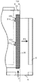
도 1a는 두 인접한 짧은 에지들(1b, 1c)이 폴딩 다운되고(fold down) 동일한 평면 내에서 위치될 때 일 에지 섹션(32)에서의 측압(side push)에 의해서, 제1 열에 있는 두 인접한 짧은 에지들이 도 1b에 도시된 바와 같이 변위되는 변위가능한 텅(30)에 의해 잠길 수 있음을 나타낸다. 이러한 수직 "측압" 접힘은 대체로(generally) 제2 열에 있는 제3 패널(1d)의 긴 측으로부터의 압력(P)에 의해서 활성화되는데, 상기 수직 측압 접힘은 개별 변위가능한 텅(30)을, 텅의 일부가 인접한 짧은 에지(1c)의 텅 그루브(20) 내로 변위되도록, 짧은 에지 조인트(1b)를 따라서 하지만 또한 조인트 방향(D2)에 수직하게 변위시킨다. 도 1c는 변위가능한 텅(30)이 공동(cavity)(41)을 가지는 변위 그루브(40) 내에 위치되는 것을 나타낸다. 이러한 공동은 변위가능한 텅 상의 돌출부(protrusion)(31)와 협력하여서, 에지 및 변위 그루브를 따라서 가압될 때 변위가능한 텅(30)이 또한 D2 방향으로 에지에 수직하게 그리고 인접한 패널의 텅 그루브(20) 내로 변위된다. 도 2a 내지 도 2d는 공동(41)을 형성하는 알려진 방법을 나타낸다. 얇은 톱날과 유사한 회전 공구(71)가 패널 표면과 평행한 수평면(HP) 내에서 회전하여서 공동(41)을 형성한다. 주된 불이익은 이러한 공구가 도 2d에 도시된 바와 같은 상당한(considerable) 깊이를 가지는 공동(41)을 형성할 것이라는 것이다.
Figure 1a shows a cross sectional view of two adjacent
에지에 평행하지 않은 변위 그루브가 형성되는 것을 요하는 알려진 기술에 따른 측압 잠금 시스템은 제조가 매우 어렵고 그리고 깊은 그루브들은 패널 에지의 강도(strength) 및 안정성에 악영향을 미칠 것이다. 대안으로서 에지와 평행하지 않은 일반적으로 두 부분들로 이루어진 쐐기형 텅들이 이용된다. 이러한 텅들을 고가이고 제조 및 에지 내로의 삽입이 복잡하다.
Pressure locking systems in accordance with known techniques that require that displacement grooves not parallel to the edges be formed are very difficult to manufacture and that deep grooves will adversely affect the strength and stability of the panel edges. As an alternative, wedge-shaped tongues of generally two parts, which are not parallel to the edge, are used. These tongues are expensive and complicated to manufacture and insert into the edge.
다른 기계식 잠금 시스템과 비교할 때 이러한 유형의 측압 시스템들의 주된 불이익은, 변위가능한 텅 상의 돌출부와 협력하는 공동들을 정밀하고 비용 효율적으로 형성하기가 어렵고 또한 패널 에지의 강도 및 안정성에 미치는 악영향을 회피하기 어렵다는 것이다.
The main disadvantage of this type of lateral pressure systems as compared to other mechanical locking systems is that it is difficult to precisely and cost-effectively form cavities that cooperate with the displaceable tongue projections and that adverse effects on the strength and stability of the panel edges are difficult to avoid will be.
몇몇 용어들의 정의(Definition of some terms ( DefinitionDefinition ofof SomeSome TermsTerms ))
이하의 기술에 있어서, 설치된 플로어 패널의 가시적인 표면을 "전면(front face)"으로 지칭하고, 서브 플로어와 대면하는 플로어 패널의 반대측(opposite side)을 "후면(rear face)"으로 지칭한다. 전면 및 후면 사이의 에지를 "조인트 에지"라고 지칭한다. 그와 다르다고 정의되지 않은 한, 윗(upper) 및 아랫(lower)은 전면을 향하는 것과 후면을 향하는 것을 의미한다. 안쪽(inner) 및 바깥쪽(outer)은 패널의 중심을 향하거나 또는 중심으로부터 멀어지는 것을 의미한다. "수평면"은 표면 레이어의 바깥쪽 부분에 평행하게 연장하는 평면을 의미한다. 주 조인된 플로어 패널들의 두 인접한 조인트 에지들의 직접 병치된(immediately juxtaposed) 윗 부분들은 함께 수평면에 수직한 "수직면"을 정의한다. "수평하게"는 수평면에 평행하다는 것을 의미하고, "수직하게"는 수직면에 평행한 것을 의미한다.
In the following description, the visible surface of the installed floor panel will be referred to as the "front face ", and the opposite side of the floor panel facing the subfloor will be referred to as the" rear face ". The edges between the front and back surfaces are referred to as "joint edges ". Unless defined otherwise, the upper and lower sides refer to the front and back, respectively. The inner and outer mean that they are directed towards or away from the center of the panel. "Horizontal plane" means a plane extending parallel to the outer portion of the surface layer. The directly juxtaposed upper portions of two adjacent joint edges of the main joined floor panels together define a "vertical plane" perpendicular to the horizontal plane. "Horizontal" means parallel to a horizontal plane, and "Vertically" means parallel to a vertical plane.
"조인트" 또는 "잠금 시스템"은 수직하게 및/또는 수평하게 플로어 패널들을 연결하는 상호 작용(co-acting) 연결 수단을 의미한다. "스트립 패널(strip panel)"은 스트립 및 잠금 요소를 포함하는 패널 에지를 의미하고, "그루브 패널(groove panel)"은 수평 잠금에 있어서 잠금 요소와 협력하는 잠금 그루브를 포함하는 패널 에지들을 의미한다.
"Joint" or "locking system" means a co-acting connection means for connecting the floor panels vertically and / or horizontally. "Strip panel" means a panel edge including a strip and a locking element, and "groove panel" means a panel edge including a locking groove cooperating with a locking element in a horizontal locking .
"수직 가압 접힘(vertical push folding)"은 앵글링 후에 서브 플로어 상에 평평하게 놓여져 있을 때 두 패널들의 짧은 에지들이 잠기는 설치 방법을 의미한다. 짧은 에지들의 긴 방향으로 개별 텅을 변위시키는 측압에 의해서 수직 잠금이 얻어진다. 그루브 패널의 다른 에지 상에서 잠금 그루브와 협력하는 스트립 패널의 하나의 에지 내 잠금 요소를 구비하는(with) 앵글링 시스템들과(as for) 동일한 방식으로 통상적인(conventional) 폴딩 다운 시스템들에서 수평 잠금이 얻어진다. "측압 잠금 시스템"은 수직 가압 접힘 방법에 의해서 잠길 수 있는 잠금 시스템을 의미한다.
"Vertical push folding" means a mounting method in which the short edges of two panels are locked when laid flat on the subfloor after angling. Vertical locks are obtained by lateral pressure displacing the individual tongues in the longitudinal direction of the short edges. In the same way as angling systems with a locking element in one edge of the strip panel cooperating with the locking groove on the other edge of the groove panel, . "Side pressure locking system" means a locking system that can be locked by a vertical pressure folding method.
"텅 폭"은 텅의 가장 바깥쪽 및 안쪽 부분과 접촉하는 텅의 길이를 따라 두 평행한 라인들 간의 최대 거리를 의미한다.
"Tongue width" means the maximum distance between two parallel lines along the length of the tongue contacting the outermost and inner portions of the tongue.
발명의 요약(SUMMARY OF THE INVENTION SummarySummary ofof thethe InventionInvention ))
본 발명의 일반적인(general) 목적은 변위가능한 텅이 에지를 따라 변위될 때 하나의 그루브로부터 에지에 평행하게 그리고 인접한 그루브 내로 변위가능한 텅을 이동시킬 수 있는 측압 잠금 시스템 및 특히 그러한 부분들의 기능 및 강도를 향상시키는 것이다.
It is a general object of the present invention to provide a side pressure locking system which is capable of moving a displaceable tongue from one groove in parallel to the edge and into adjacent grooves when the displaceable tongue is displaced along the edge, .
본 발명의 제1 양태에 따르면, 플로어 패널들은 수직 잠금을 위해서 제1 에지 내 변위 그루브 내 변위가능한 텅 그리고 인접한 제2 에지들 내 텅 그루브를 포함하는 잠금 시스템을 구비한다. 제1 에지 내 잠금 요소를 구비하는 잠금 스트립은 수평 잠금을 위해 제2 에지 내 잠금 그루브와 협력한다. 변위가능한 텅은 돌출부를 포함하고 변위 그루브는 공동을 포함하는데, 상기 변위가능한 텅이 에지를 따라서 제2 방향으로 변위될 때 상기 에지에 수직한 제1 방향으로 그리고 상기 공동의 벽에 대항하여 상기 돌출부가 미끄러진다. 제1 방향으로의 변위는 상기 변위가능한 텅이 상기 텅 그루브 내로 들어가도록 야기하고 이에 의해서 상기 에지들이 수직으로 잠길 수 있다. 상기 플로어 패널의 후방 측에 대하여 수직 하향으로 상기 공동이 연장된다.
According to a first aspect of the invention, the floor panels have a locking system comprising a displaceable tongue in the displacement groove in the first edge and a tongue groove in the adjacent second edges for vertical locking. The locking strip with the locking element in the first edge cooperates with the locking groove in the second edge for horizontal locking. Wherein the displaceable tongue comprises a protrusion and the displacement groove comprises a cavity in which the displaceable tongue protrudes in a first direction perpendicular to the edge when the displaceable tongue is displaced in a second direction along the edge and against the wall of the cavity, . Displacement in a first direction causes the displaceable tongue to enter the tongue groove, whereby the edges can be vertically locked. And the cavity extends vertically downward with respect to the rear side of the floor panel.
본 발명의 제1 양태의 이점은 공동들을 형성하기 위해 간단한 기계가공(machining)이 사용될 수 있고 이러한 형성이 에지의 강도 및 안정성에 악영향을 미치지 아니할 것이라는 것이다.
An advantage of the first aspect of the present invention is that simple machining can be used to form the cavities and such formation will not adversely affect the strength and stability of the edge.
바람직한 실시예에 따르면 공동은 실질적으로 수직인 수직 벽에 의해 둘러싸인 블라인드 홀이다.
According to a preferred embodiment, the cavity is a blind hole surrounded by a substantially vertical wall.
이러한 공동은 극단적으로 안정적인 에지를 제공하고 최소의 물질이 제거되어야 한다.
These cavities provide extremely stable edges and require minimal material removal.
본 발명의 제2 양태에 따르면, 잠금 시스템을 구비하는 플로어 패널들에 있어서, 잠금 시스템이 수직 잠금을 위해서 제1 에지 내 변위 그루브 내 변위가능한 텅 그리고 인접한 제2 에지들 내 텅 그루브를 포함한다. 제1 에지 내 잠금 요소를 구비하는 잠금 스트립이 수평 잠금을 위하여 제2 에지 내 잠금 그루브와 협력한다. 변위가능한 텅은 돌출부를 포함하고 변위 그루브는 공동을 포함하는데, 상기 변위가능한 텅이 에지를 따라서 제2 방향으로 변위될 때 상기 에지에 수직한 제1 방향으로 그리고 상기 공동의 벽에 대항하여 상기 돌출부가 미끄러진다. 제1 방향으로의 변위는 상기 변위가능한 텅이 상기 텅 그루브 내로 들어가도록 야기하고 이에 의해서 상기 에지들이 수직으로 잠길 수 있다. 돌출부는 가요성이고 텅 그루브에 대항하여 수평 예비 인장을 가하도록 구성된다.
According to a second aspect of the present invention there is provided a floor panel comprising a locking system, wherein the locking system comprises a displaceable tongue in the displacement groove in the first edge and a tongue groove in the adjacent second edges for vertical locking. A locking strip with a locking element in the first edge cooperates with the locking groove in the second edge for horizontal locking. Wherein the displaceable tongue comprises a protrusion and the displacement groove comprises a cavity in which the displaceable tongue protrudes in a first direction perpendicular to the edge when the displaceable tongue is displaced in a second direction along the edge and against the wall of the cavity, . Displacement in a first direction causes the displaceable tongue to enter the tongue groove, whereby the edges can be vertically locked. The protrusions are flexible and configured to apply a horizontal pretension against the tongue grooves.
제2 양태는 제조 공차(production tolerances)의 부정적인 영향을 줄일 수 있고 향상된 잠금 품질에 이를 수 있다는 이점을 제공한다.
The second aspect provides the advantage of being able to reduce the negative impact of production tolerances and to achieve improved locking quality.
본 발명의 제3 양태에 따르면 잠금 시스템을 구비하는 플로어 패널들에 있어서, 잠금 시스템이 수직 잠금을 위해서 제1 에지 내 변위 그루브 내 변위가능한 텅 그리고 인접한 제2 에지들 내 텅 그루브를 포함한다. 제1 에지 내 잠금 요소를 구비하는 잠금 스트립이 수평 잠금을 위하여 제2 에지 내 잠금 그루브와 협력한다. 변위가능한 텅은 돌출부를 포함하고 변위 그루브는 공동을 포함하는데, 상기 변위가능한 텅이 에지를 따라서 제2 방향으로 변위될 때 상기 에지에 수직한 제1 방향으로 그리고 상기 공동의 벽에 대항하여 상기 돌출부가 미끄러진다. 제1 방향으로의 변위는 상기 변위가능한 텅이 상기 텅 그루브 내로 들어가도록 야기하고 이에 의해서 상기 에지들이 수직으로 잠길 수 있다. 돌출부는 변위가능한 텅의 아랫 및/또는 윗 부분 상에 위치된다.
According to a third aspect of the present invention there is provided a floor panel having a locking system, wherein the locking system comprises a displaceable tongue in the displacement groove in the first edge and a tongue groove in the adjacent second edges for vertical locking. A locking strip with a locking element in the first edge cooperates with the locking groove in the second edge for horizontal locking. Wherein the displaceable tongue comprises a protrusion and the displacement groove comprises a cavity in which the displaceable tongue protrudes in a first direction perpendicular to the edge when the displaceable tongue is displaced in a second direction along the edge and against the wall of the cavity, . Displacement in a first direction causes the displaceable tongue to enter the tongue groove, whereby the edges can be vertically locked. The protrusions are located on the bottom and / or top of the displaceable tongue.
제3 양태가 제공하는 이점은 작은 깊이를 가진 변위 그루브가 형성될 수 있고 향상된 안정성 및 강도에 이를 수 있다는 것이다.
An advantage provided by the third aspect is that a displacement groove with a small depth can be formed and can achieve improved stability and strength.
본 발명의 제4 양태에 따르면, 잠금 시스템을 구비하는 일 세트의 플로어 패널들에 있어서, 상기 잠금 시스템은 메인 텅 바디 그리고 제1 플로어 패널의 제1 에지 내 변위 그루브 내에 위치된 둘 이상의 쐐기부들을 구비하는 변위가능한 텅으로서, 에지들의 수직 잠금을 위해서 제2 플로어 패널의 인접한 제2 에지 내 텅 그루브와 협력하는 변위가능한 텅을 포함한다. 상기 잠금 시스템은 하나의 에지 내 잠금 요소를 구비하는 잠금 스트립으로서, 에지들의 수평 잠금을 위해 인접한 에지 내 잠금 그루브와 협력하는 잠금 스트립을 더 포함한다. 상기 메인 텅 바디는 둘 이상의 가요성 돌출부들 및 둘 이상의 리세스들을 포함한다. 상기 쐐기부들은 적어도 부분적으로 상기 리세스들 내에 위치된다. 에지들에 수직하게 상기 메인 텅 바디의 변위가 얻어질 수 있도록 상기 가요성 돌출부들은 상기 쐐기부들에 대항하여 미끄럼가능함으로써 상기 에지들의 수직 잠금이 이루어질 수 있다. 상기 가요성 돌출부들은 풀린(unlocked) 위치에서 상기 쐐기부들에 대하여 실질적으로(essentially) 상기 변위가능한 텅을 따라서 변위되고, 상기 텅 그루브 및 상기 쐐기부들에 대항하여 예비 인장을 가하도록 구성된다. 상기 메인 텅 바디는 상기 변위 그루브를 따르는 변위를 허용하되 상기 메인 텅 바디가 상기 변위 그루브 밖으로 이탈되는 것을 방지하는 마찰 접합부(friction connection)를 포함한다. 상기 쐐기부들은 상기 메인 텅 바디가 에지를 따라서 변위될 때 상기 쐐기부들이 상기 변위 그루브 내에서 변위되어지는 것을 방지하는 마찰 접합부를 포함한다. 상기 쐐기부들 및 상기 메인 텅 바디는 상기 변위가능한 텅이 상기 변위 그루브 내로 삽입되는 동안 릴리스되어지게 구성된 릴리스가능한 쐐기부 접합부들(wedge part connections)을 포함한다.
According to a fourth aspect of the present invention there is provided a set of floor panels having a locking system comprising a main tongue body and two or more wedges positioned within a displacement groove in a first edge of the first floor panel, And a displaceable tongue cooperating with a tongue groove in an adjacent second edge of the second floor panel for vertical locking of the edges. The locking system further includes a locking strip having locking elements in one edge, the locking strip cooperating with locking grooves in adjacent edges for horizontal locking of the edges. The main tongue body includes two or more flexible protrusions and two or more recesses. The wedges are at least partially located within the recesses. The flexible protrusions may be slidable against the wedges so that a vertical displacement of the edges can be achieved so that a displacement of the main tongue body perpendicular to the edges can be obtained. The flexible protrusions are configured to substantially displace along the displaceable tongue with respect to the wedge portions in an unlocked position and to apply a preliminary tension against the tongue groove and the wedge portions. The main tongue body includes a friction connection that allows displacement along the displacement groove but prevents the main tongue body from being disengaged from the displacement groove. The wedges include a friction joint that prevents the wedges from being displaced within the displacement groove when the main tongue body is displaced along an edge. The wedges and the main tongue body include releasable wedge part connections configured to be released while the displaceable tongue is inserted into the displacement groove.
제4 양태가 제공하는 이점은 통상적인 기계식 잠금 시스템들과 동일한 방식으로 에지들에 평행한 간단한 기계가공(machining)만으로 에지가 형성될 수 있다는 것이다. 변위가능한 텅은 단일-피스 부품(one-piece component)으로사 비용 효율적인 방식으로 형성될 수 있고 텅을 그루브 내로 제어되게 삽입하는 동안 2-피스 부품(two-piece component)으로 변환될 수 있다.
The advantage provided by the fourth aspect is that the edge can be formed by simple machining parallel to the edges in the same way as conventional mechanical locking systems. The displaceable tongue can be formed in a cost effective manner with a one-piece component and can be converted into a two-piece component while the tongue is controlledly inserted into the groove.
본 발명의 제5 양태에 따르면, 텅 길이를 가지고 서로 연결되는 둘 이상의 텅들을 포함하는 텅 블랭크가 제공된다. 텅들은 서로로부터 분리되고 플로어 패널의 에지 그루브 내로 삽입되도록 구성된다. 각각의 텅은 실질적으로 텅 길이 방향으로 연장되는 둘 이상의 돌출부들 그리고 둘 이상의 리세스들을 포함하는 메인 텅 바디를 포함한다. 텅은 적어도 부분적으로 상기 리세스들 내에 또는 상기 리세스들에 인접하여 위치된 두 개의 쐐기부들을 포함한다. 상기 메인 텅 바디 및 상기 쐐기부들은 상기 변위가능한 텅이 상기 변위 그루브 내로 삽입되는 동안 상기 메인 텅 바디로부터 릴리스되어지게 구성된 릴리스가능한 쐐기부 접합부들을 포함한다.
According to a fifth aspect of the present invention, there is provided a tongue blank including two or more tongues connected to each other with a tongue length. The tongues are configured to be separated from each other and to be inserted into the edge grooves of the floor panel. Each tongue includes a main tongue body that includes two or more protrusions and two or more recesses that extend substantially in a tongue longitudinal direction. The tongue includes at least partially two wedges located within or adjacent to the recesses. The main tongue body and the wedge portions include releasable wedge portion joints configured to be released from the main tongue body while the displaceable tongue is inserted into the displacement groove.
제5 양태가 제공하는 이점은 간단하고 비용 효율적인 방식으로 텅들이 제조될 수 있고 핸들링될 수 있고 그리고 그루브 내로 삽입될 수 있다는 것이다.
The advantage provided by the fifth aspect is that the tongs can be manufactured and handled in a simple and cost-effective manner and can be inserted into the grooves.
제1 양태, 제2 양태, 제3 양태, 제4 양태, 및 제5 양태의 모든 실시예들은 결합될 수 있고 예를 들어 가요성 돌출부는 후방 측까지 연장되고 변위가능한 텅의 윗 및/또는 아랫 측 상에 위치된 공동과 함께 사용될 수 있다.
All embodiments of the first, second, third, fourth and fifth aspects may be combined, for example the flexible protrusions may extend to the rear side and may be provided at the top and / or bottom of the displaceable tongue Lt; / RTI > can be used with the cavity located on the side.
본 발명은 바람직하게는 짧은 에지들에서 하지만 또한 긴 에지들에서 또는 정사각형 패널들에서 잠금 시스템들에 관한 새로운 실시예들을 제공한다. 본 발명이 유용한 기술 분야는 임의의 형태 및 물질(예를 들어 라미네이트)로 이루어진 벽 패널, 천장, 외부 어플리케이션(exterior applications) 및 플로어 패널; 특히 열경화성 수지(thermosetting resin), 목재, HDF, 단판(veneer), 또는 돌을 포함하는 표면 물질들을 가지는 패널들이다.
The present invention preferably provides new embodiments of locking systems at short edges but also at long edges or in square panels. Technical fields useful in the present invention include wall panels, ceilings, exterior applications and floor panels made of any shape and material (e.g., laminates); Especially panels with surface materials including thermosetting resins, wood, HDF, veneers, or stones.
잠금 시스템의 거의 모든 실시예들에 있어서 스트립 패널 상에 변위가능한 텅 그리고 변위 그루브를 구비하는 것으로 기술되는데 주로 설명을 단순화하기 위해서다. 본 발명 또는 주된 원리가 잠금 그루브 측에서도 사용될 수 있음은 자명하다. 텅이 일 에지 내 변위 그루브 내로 삽입되는데 이것은 인접하게 바람직하게는 잠금 그루브 너머에(above) 위치되고 그리고 텅 그루브는 잠금 스트립에 인접하게 바람직하게는 실질적으로 스트립 너머에(above) 위치된 다른 에지 내에 형성된다.
It is described as having displaceable tongues and displacement grooves on the strip panel in almost all embodiments of the locking system, primarily for the sake of simplicity. It will be appreciated that the present invention or principle may be used on the lock groove side as well. The tongue is inserted into the displacement groove in the edge, which is preferably located adjacent to the locking groove above and the tongue groove is located adjacent to the locking strip, preferably substantially at the other edge located above the strip .
도 1a 내지 도 1d는 종래 기술에 따른 잠금 시스템을 나타낸다.
도 2a 내지 도 2c는 패널의 일 에지 내 공동에 대한 종래 기술에 따른 제조 방법을 나타낸다.
도 3a 내지 도 3f는 패널의 일 에지 내 공동들을 형성하는 제조 방법을 나타낸다.
도 4a 내지 도 4d는 패널의 일 에지 내 공동들을 형성하는 대안적인 제조 방법을 나타낸다.
도 5a 내지 도 5d는 패널의 일 에지 내 공동들을 형성하기 위해 스크류 커터를 사용하는 제조 방법을 나타낸다.
도 6a 및 도 6b는 코어 상에 표면 레이어를 적용하는 것에 앞서 패널의 코어에 어떻게 공동들이 형성될 수 있는가를 나타낸다.
도 7a 내지 도 7d는 톱날들에 의해 형성된 공동들을 구비하는 잠금 시스템을 나타낸다.
도 8a 내지 도 8e는 드릴링된 블라인드 홀로서 커터들에 의해 형성된 공동을 구비하는 잠금 시스템을 나타낸다.
도 9a 내지 도 9c는 커터들에 의해 형성된 수평 개방된 공동들을 구비하는 잠금 시스템을 나타낸다.
도 10a 내지 도 10e는 가요성 돌출부들을 포함하는 변위가능한 텅을 구비하는 잠금 시스템을 나타낸다.
도 11a 내지 도 11d는 텅의 아랫 부분에서 돌출부들을 포함하는 변위가능한 텅을 구비하는 잠금 시스템을 나타낸다.
도 12e 내지 도 12f는 텅의 윗 및/또는 아랫 부분들 상 돌출부들을 포함하는 변위가능한 텅을 구비하는 잠금 시스템을 나타낸다.
도 13a 내지 도 13d는 변위가능한 텅의 아랫 부분 상 가요성 돌출부들을 나타내고 그리고 안정적이고 강한 에지를 형성하기 위한 제조 방법들을 나타낸다.
도 14a 내지 도 14d는 수직 회전하는 톱날에 의해 형성된 공동들을 구비하는 잠금 시스템을 나타낸다.
도 15a 및 도 15b는 수평 회전하는 톱날에 의해 형성된 공동들을 구비하는 잠금 시스템을 나타낸다.
도 16a 및 도 16b는 긴 에지 잠금 시스템 형성과 관련하여 형성된, 공동들을 이용하는 잠금 시스템을 나타낸다.
도 17a 및 도 17b는 돌출부들과 협력하는 스파이크들(spikes)을 구비하는 잠금 시스템을 나타낸다.
도 18a 내지 도 18e는 리세스와 협력하는 스파이크들을 구비하는 잠금 시스템을 나타내고 그리고 그루브 패널 상 변위가능한 텅을 포함하는 일 실시예를 나타낸다.
도 19a 내지 도 19e는 단일 피스 변위가능한 텅으로서 삽입 후에 수 개의(several) 분리된(unconnected) 부분들로 분리되는 단일 피스 변위가능한 텅을 구비하는 잠금 시스템을 나타낸다.
도 20a 내지 도 20d는 본 발명에 따라서 텅이 그루브 내로 삽입되는 것과 잠금 시스템이 잠기는 것을 나타낸다.
도 21a 내지 도 21c는 텅을 그루브 내에 위치시키는 방법을 나타낸다.
도 22a 내지 도 22d는 잠금 동안 플로어 패널의 에지 및 텅 블랭크를 나타낸다.
도 23a 내지 도 23f는 잠금 동안 플로어 패널의 에지에서의 잠금 시스템 및 텅 블랭크들을 나타낸다.
도 24a 내지 도 24f는 본 발명의 주된 원리들에 따른 실시예들을 나타낸다.1A to 1D show a locking system according to the prior art.
Figures 2a to 2c show a prior art manufacturing method for a cavity in one edge of a panel.
Figures 3A-3F illustrate a method of making cavities in one edge of a panel.
4A-4D illustrate an alternative method of forming cavities in one edge of the panel.
Figures 5A-5D illustrate a method of making a screw cutter to form cavities in one edge of the panel.
Figures 6a and 6b show how cavities can be formed in the core of the panel prior to applying the surface layer on the core.
Figures 7a-7d show a locking system with cavities formed by saw blades.
Figures 8A-8E illustrate a locking system with cavities formed by drilled blind hole cutters.
Figures 9a-9c illustrate a locking system with horizontally open cavities formed by cutters.
Figures 10A-10E illustrate a locking system with a displaceable tongue that includes flexible protrusions.
11a-11d illustrate a locking system with a displaceable tongue that includes protrusions at the bottom of the tongue.
Figures 12E-12F illustrate a locking system with a displaceable tongue that includes top and / or bottom portions of the tongue top protrusions.
13A-13D illustrate flexible protrusions on the lower portion of a displaceable tongue and illustrate fabrication methods for forming a stable and strong edge.
Figures 14a-d show a locking system with cavities formed by vertically rotating saw blades.
15A and 15B show a locking system with cavities formed by horizontally rotating saw blades.
16A and 16B show a locking system using cavities formed in connection with the formation of a long edge locking system.
17A and 17B show a locking system with spikes cooperating with the protrusions.
Figures 18a-e illustrate an embodiment that includes a locking system with spikes cooperating with recesses and including a tongue that is displaceable on the groove panel.
19A-19E illustrate a locking system with a single piece displaceable tongue that is separated into several unconnected portions after insertion as a single piece displaceable tongue.
20A-20D illustrate that the tongue is inserted into the groove and the locking system is locked in accordance with the present invention.
Figures 21a-21c illustrate a method of positioning a tongue in a groove.
Figures 22A-22D show the edge and tongue blank of the floor panel during locking.
23A-23F illustrate locking systems and tongue blanks at the edge of a floor panel during locking.
24A-24F illustrate embodiments in accordance with the main principles of the present invention.
도 3a 내지 도 3e는 커터 원리에 따라서 공동들(41a 내지 41d)을 형성하는 제조 방법을 나타낸다. 수 개의(several) 커터들(70a 내지 70d)이 각각의 공동에 대하여 하나씩 사용될 수 있다. 이러한 형성은 프로파일 형성 전 또는 후에 이루어질 수 있다. 도 3a는 커터가 커터의 직경보다 작은 공동을 형성할 수 있는 것을 나타낸다. 도 3e는 패널 및 공구가 서로에 대하여 변위된다면 형성될 수 있는 커터의 직경보다 큰 공동을 나타낸다. 도 3f는 채워진(solid) 윗 부분 및 개구를 포함하는 블라인드 홀로서 형성된 공동을 나타낸다.
3A to 3E show a manufacturing method of forming the
도 4a 내지 도 4d는 앞서 언급한 형성이 또한 톱날 원리에 의해서 이루어질 수 있는 것을 나타내는데, 이러한 톱날 원리에 있어서 바람직하게는 동일한 축선들(axes) 상에서 바람직하게는 수 개의 톱날들(71a 내지 71d)이 공동들(41a 내지 41d)을 형성한다. 이러한 실시예에 있어서 공동들은 톱날들의 직경보다 더 작다. 그러나 톱날들의 직경과 같거나 그보다 클 수 있음은 물론이다.
4A-4D illustrate that the above-mentioned formation can also be made by the sawtooth principle, in which a number of
도 5a 내지 도 5d는 스크류 커터 원리를 이용하여 앞서 언급한 공동들(41a 내지 41f)을 형성하는 방법을 나타낸다. 특히 패널 위치 및 속도가 공구 위치 및 공구 회전 속도와 정확하게 동기화된다면, 이러한 형성은 높은 정확도를 가지고 연속 제조 라인에서 매우 비용 효율적인 방식으로 이루어질 수 있다. 스크류 커터(72)는 별개 장비로서 또는 보다 바람직하게는 더블-엔드 테노너(double-end tenoner) 내 일체화된 공구 위치(integrated tool position)로서 사용될 수 있다. 패널 에지는 스크류 커터 공구(72)의 회전축(AR)에 실질적으로 평행하게 변위된다. 둥글거나 모서리를 가지는(sharp) 공동들을 구비하는 임의의 형태를 생성하는 것이 가능하다. 커팅은 프로파일 커팅 이전 또는 이후에 또는 이와 연계되어 이루어질 수 있다.
Figs. 5A to 5D show a method of forming the above-mentioned
패널 에지 상에 형성된 공동의 길이 방향의 위치는 도 5c에 도시된 바와 같이 패널 에지와 접촉하게 되는 제1 입구 공구 치형부(entrance tool tooth)(56a)의 위치에 따라서 달라진다. 이것은 공구의 회전이 공구를 향하여 이동하는 패널 에지에 대하여 조정되어야만 함을 의미한다. 공구 회전이 조정되고 스크류 커터에 대하여 패널이 변위되는 속도와 동기화된다면 공동들 간의 위치가 매우 정확해질 수 있다. 이러한 공구 회전 및 제1 입구 공구의 위치의 조정은 패널 에지의 위치 그리고 이송 체인(transportation chain) 또는 벨트 또는 체인 또는 벨트를 움직이는 구동 장치의 속도를 측정하는 것에 의해서 이루어질 수 있다. 공동들을 매우 정확하게 기계가공하는 것이 가능하고 또한 약 ± 0.2 mm 또는 그 이하의 공차(tolerance)를 가지면서 에지로부터 기결정된 위치에 제1 공동을 위치시키는 것이 가능하다. 도시된 스크류 커터 공구(72)의 직경(53)은 바람직하게는 반대편 출구 측(opposite exit side) 상에서보다 입구 측(ES) 상에서 더 작아야 한다. 그러나 스크류 커터 공구는 전체 길이(54)에 걸쳐서 동일한 직경(53)을 가질 수도 있다. 이러한 공구 구성에 있어서 패널 에지의 피딩 방향(feeding direction)에 대하여 다소 각진 회전축에 의해서 증가된 커팅 깊이에 이를 수 있다.
The longitudinal position of the cavity formed on the panel edge is dependent on the position of the first
공구 구성의 피치(pitch)(55)는 공동들의 중간 거리(intermediate distance)를 정의한다. 따라서 조인트의 상당한 길이에 걸쳐서 매우 정확한 중간 거리들을 가지는 다수의 공동들 및 돌출부들을 매우 용이하게 형성할 수 있다. 스크류 커터의 치형부(56)는 바람직하게는 공업용 다이아몬드로 이루어진다.
The
또한 공구 바디의 단지 일부 상에 커팅 치형부를 포함하는, 톱날에 유사한 대형 회전 공구에 의해 공동들이 형성될 수 있다. 이것은 스크류 커터 원리의 간단한 변형이고 각각의 회전이 하나의 공동을 형성한다. 이점은 공동들 간의 중간 거리가 패널의 피딩 속도 또는 공구 회전 속도의 조정에 의해서 변화될 수 있다는 것이다.
Cavities may also be formed by a large rotating tool similar to a saw blade, including a cutting tooth on only a portion of the tool body. This is a simple modification of the screw cutter principle and each rotation forms one cavity. The advantage is that the intermediate distance between the cavities can be varied by adjusting the feed rate of the panel or the tool rotational speed.
스크류 커터가 프로파일링 장비와 일체화된다면 패널의 변위가 정지되는 계획되거나 계획되지 않은 제조 단계들이 문제되는데, 스크류 커터가 공구 치형부와 접촉하는 패널의 모든 공동들을 파괴할 것이기 때문이다. 이러한 문제는 몇몇(some) 또는 모든 단계들이 독립적으로 또는 조합되어 사용될 수 있는 후술하는 단계들을 포함하는 제조 방법들에 의해서 해결될 수 있다.
If the screw cutter is integrated with the profiling equipment, the planned or unplanned manufacturing steps of stopping the displacement of the panel will be problematic because the screw cutter will destroy all the cavities of the panel in contact with the tool teeth. This problem can be solved by manufacturing methods that include the steps described below, some or all of which may be used independently or in combination.
a) 패널이 항상 스크류 커터 공구를 지나갔을 때 그리고 패널 에지 상에 위치된 모든 공동들의 완전한 제조 후에 정지된다. 이러한 방법은 모든 계획된 정지들에 대하여 사용된다. 에지 상 모든 공동들의 완전한 제조를 허용하지 아니하는 위치에서 패널이 정지되었을 때 스크류 커터는 패널 에지로부터 멀어지게 변위된다. 부분적으로 제조된 공동들을 구비하는 이러한 패널들은 탐지되고 정상적인(normal) 제조로부터 거절된다(reject).
a) The panel is always stopped after passing the screw cutter tool and after complete manufacture of all cavities located on the panel edge. This method is used for all planned stops. The screw cutter is displaced away from the panel edge when the panel is stopped in a position that does not allow complete manufacture of all cavities on the edge. These panels with partially manufactured cavities are detected and rejected from normal manufacturing.
b) 패널이 정지되었을 때 패널 에지로부터 멀어지게 스크류 커터가 변위된다. 그러면 이송 장치가 역전된다. 스크류 커터가 그 원래 위치로 되돌아가게 이동되고 패널이 정상적인 방식으로 제조된다.
b) When the panel is stopped, the screw cutter is displaced away from the panel edge. The transport is then reversed. The screw cutter is moved back to its original position and the panel is manufactured in a normal manner.
c) 패널이 정지되었을 때 패널들의 피딩 방향에 대항하여 그리고 패널 에지에 평행하게 변위될 수 있는 것이 허용되게 하는 이동 장치(moving device)를 스크류 커터가 포함한다. 스크류 커터는 그 치형부가 정지된 패널의 패널 에지를 지나도록 변위된다. 심지어 비상 브레이크(emergency break)가 발생했을 때에도 모든 공동들은 항상 완전히 기계가공될 것이다. 이송 장치가 시작되고 새로운 패널이 정상적인 방식으로 제조될 때 스크류 커터가 그 원래 위치로 되돌아간다.
c) the screw cutter includes a moving device that allows it to be displaced parallel to the panel edge and against the feeding direction of the panels when the panel is stopped. The screw cutter is displaced such that the teeth of the cutter pass through the panel edge of the stationary panel. Even when an emergency break occurs, all cavities will always be fully machined. When the transfer device is started and the new panel is manufactured in the normal way, the screw cutter returns to its original position.
앞서 c)에서 기술된 바와 같은 변위가능한 스크류 커터 방법이 제공하는 이점은 이송 장치 또는 제어 시스템의 어떠한 변형 없이도 통상적인 프로파일링 장비가 사용될 수 있다는 것이다.
An advantage provided by the displaceable screw cutter method as described in c) above is that conventional profiling equipment can be used without any modification of the transfer device or control system.
스크류 커터에 의해 공동들을 형성하는 앞서 기술한 제조 방법들은 모든 유형의 패널 기계가공에 있어서 그리고 특히 플로어 패널들에 대한 기계식 잠금 시스템의 부분들을 포함하는 공동들이 형성되는 이러한 기계가공에 있어서 사용될 수 있다.
The above-described manufacturing methods for forming cavities by means of screw cutters can be used in such machining in which cavities are formed in all types of panel machining, and in particular, including parts of a mechanical lock system for floor panels.
도 6a 내지 도 6b는 프로파일 컷 전 이전에 공동들의 형성이 이루어질 수 있음을 나타낸다. 돌출부들 공동들(41a)을 구비하는 별개 물질(62) 또는 패널 코어가 플로어보드의 에지에 연결될 수 있고 바람직하게는 목재 또는 라미네이트 플로어 내(in) 밸런싱 레이어(61) 및 표면 레이어(60) 사이에 접착될(glue) 수 있다.
Figures 6A-6B show that the formation of cavities can be made before the profile cut. A
도 7a 내지 도 7d는 에지 내 공동들을 형성하기 위한 기술된 방법들이 하나의 변위 그루브(40)로부터 도 1a 내지 도 1d에서 설명한 바와 같이 인접한 텅 그루브(20) 내로 변위가능한 텅(30)을 변위시키는 데 사용될 수 있는 것을 나타낸다. 수평으로 연장된 기울어지거나 평행한 벽들을 구비하는 하나 또는 수개의 공동들(41a 내지 41c)이 스트립(6)을 통한(trough) 커팅에 의해서 형성될 수 있고 이러한 실시예 및 제조 방법은 공동을 만들기 위해 얇은 수평 커팅 톱날들이 사용될 수 있는 알려진 방법들보다 보다 비용 효율적이다. 공동들은 바람직하게는 동일한 공구 샤프트 상에 장착된 점핑 공구 헤드들(71a-71c)에 의해서 형성될 수 있는데 이것은 패널이 점핑 공구 헤드들에 대하여 변위될 때 후방 측을 향하여 변위된다. 물론 패널은 수직으로 또는 수평으로 톱날들을 향하여 변위될 수도 있다. 점핑 헤드들은 긴 에지들을 형성하는 동일한 기계 내에 장착될 수 있고 공동들의 형성은 잠금 시스템의 형성과 일치되게(in line with) 비용 효율적인 방식으로 이루어질 수 있다. 점핑 헤드들은 또한 피딩 방향을 따라서 변위될 수 있고 패널 에지의 변위 및 점핑 헤드들의 변위 간의 상대 속도 또한 회전하는 공구들의 폭보다 더 큰 개구를 구비하는 공동들을 얻는 데에 사용될 수 있다. 또한 점핑 비-회전식 절삭 공구들(jumping non-rotating scraping tools)이 공동들 또는 돌출부들을 형성하는 데에 사용될 수 있다. 도 7c는 공동들(41a 내지 41c) 내에 위치된 돌출부들(31a 내지 31c)을 구비한 풀린 위치에서의 변위가능한 텅을 나타낸다. 도 7d는 변위가능한 텅(30)의 에지 섹션(32)에 가해진 측압(side pressure)(P)에 의해 에지를 따라서 상기 텅(30)이 변위되었을 때 잠긴 위치를 나타낸다. 돌출부는 이러한 변위 동안 공동들의 벽들을 따라서 미끄러질 것이고 텅이 에지에 수직하게(PD) 움직여서 인접한 텅 그루브(20) 내로 잠기도록 강요할 것이다.
Figures 7a-7d illustrate how the described methods for forming cavities in the edge displace
도 8a 내지 도 8e는 블라인드 홀로서 형성된 공동(41a)을 구비하는 실시예를 나타낸다. 예를 들어 5-15 mm의 직경을 가진 커터가 사용될 수 있고 블라인드 홀들로서 성형된 하나 또는 수개의 공동들(41a 내지 41c)이 도 8a 내지 도 8c에 도시된 바와 같이 후방 측으로부터 형성될 수 있다. 패널 및/또는 커터는 기계가공 동안 서로를 향하여 수직하게 변위된다. 공동들은 잠금 동안 도 8d 내지 도 8e에 도시된 바와 같이 텅(30)의 안쪽 부분 상에 위치된 돌출부들(31a 내지 31d)과 협력하도록 위치될 수 있다. 이러한 실시예는 매우 강하고 안정적인 에지를 형성하는 것을 가능하게 하는데, 커터들이 매우 작은 양의 물질만을 제거할 것이기 때문이다.
8A to 8E show an embodiment having a
도 9a 내지 도 9c는 커터에 의해 형성되는 공동들(41a 내지 41d)을 구비하는 실시예를 도시하는데, 커터 및/또는 패널이 기계가공 동안 수평으로 변위된다. 몇몇 어플리케이션에 있어서 이러한 제조 방법을 사용하는 것이 이점을 가질 수 있다. 커터들은 예를 들어 마찬가지로 패널의 피딩 방향을 따라 변위될 수 있는 점핑 공구 헤드에 대하여 정적이거나 고정적일 수 있다.
Figures 9a-9c illustrate an embodiment with
도 1Oa 내지 도 1Oe는 돌출부들(31a 내지 31c)이 가요성으로 만들어질 수 있고 이것이 제조 공차를 보상하는 데에 그리고 텅(30) 및 텅 그루브(20) 사이의 수평 예비 인장을 생성하여 수직 압력 힘(VF)이 도 10d에 도시된 바와 같이 인접한 패널 및 스트립(6)의 윗 부분 사이에 생성될 수 있도록 하는 데에 사용될 수 있음을 나타낸다. 수직 압력 힘(VF)은 바람직하게는 수평면(HP)에 대하여 다소 기울어진 텅 그루브(20) 및 텅(30) 사이 접촉 표면에 의해서 야기된다.
Figs. 10A-10E show that protrusions 31a through 31c can be made flexible, which compensates for manufacturing tolerances and creates a horizontal preload between
도 11a 내지 도 11d는 잠금 동안 공동들(41a 내지 41c)과 협력하는 돌출부들(31a 내지 31c)이 예를 들어 변위가능한 텅(30)의 아랫 부분 상에 형성될 수 있는 것을 나타낸다. 변위 그루브(40)의 깊이는 상당히 감소될 수 있고 이것은 조인트의 강도 및 습도에 대한 안정성을 증가시킬 것이다.
11a-11d show that protrusions 31a-31c cooperating with
도 12a 내지 도 12f는 돌출부(31a 내지 31c, 31a' 내지 31c')이 변위가능한 텅(30)이 윗 및/또는 아랫 부분 상에 형성될 수 있는 것을 나타낸다. 이러한 돌출부들은 잠금 동안 변위가능한 텅(30)의 메인 바디 너머에 및/또는 아래에 위치된 공동들(41a)과 협력할 수 있다.
12A to 12F show that the protruding
도 13a 및 도 13b는 변위가능한 텅(30)의 메인 바디로부터 하향으로 및/또는 상향으로 돌출되는 가요성 돌출부들(31a)이 형성될 수 있는 것을 나타낸다. 이러한 돌출부는 도 10a 내지 도 10d와 연계되어 앞서 설명한 바와 동일한 방식으로 예비 인장을 생성할 수 있다. 도 13c 및 도 13d는 변위가능한 텅(30)의 아랫 부분 상 돌출부(31a)가 도 13d에 도시된 바와 같이 상당히 더 작게 만들어질 수 있다는 이점을 가지는 것을 나타내는데, 이것은 에지의 강도를 향상시키는 데에 사용될 수 있다. 수직 회전하는 공구(71)에 의해 형성되는 공동들은 바람직하게는 공동의 윗 부분(82)에 대하여 수직하게 안쪽으로 위치된 윗 부분(81)을 포함한다. 이것은 에지에 대한 충분한 강도 및 안정성을 부여하고 비용 효율적인 제조가 가능하게 한다.
13A and 13B show that the
도 14a 및 도 14b는 아랫 부분 상 돌출부들(31a, 31b)과 회전하는 톱날들에 의해 형성된 공동들(41a, 41b)과 함께 변위가능한 텅(30)을 나타낸다. 도 14c 및 도 14d는 공동들 및 돌출부들의 모든 실시예들이 역압(counter pressure)(P')을 생성하는 데에 그리고 가요성 텅(30')을 구부리는 데에 사용될 수 있다는 것을 나타낸다. 돌출부(31a)는 공동(41a)과 협력하고 측압(P)이 가해졌을 때 텅이 변위되는 것을 방지한다. 텅(30)은 구부러지고 텅 그루브 내로 잠긴다. 이것은 텅을 구부리기 위해 인접한 열 내 긴 에지로부터 역압을 얻는 것이 가능하지 않은, 제1 열 내 패널들을 잠그는 데에 사용될 수 있다.
Figs. 14A and 14B show
도 15a 및 도 15b는 수평 회전하는 톱날들(71a 내지 71c)이 공동들(41a 내지 41c)을 형성하는 데에 사용될 수 있음을 나타내는데, 공동들은 변위가능한 텅(30)의 메인 바디 너머에 및/또는 아래에 연장되고 텅의 메인 바디 너머에 및/또는 아래에 위치된 돌출부들(31a 및 31b)와 협력한다. 하나의 톱날(71a)이 다른 톱날(71c)에 대하여 수직으로 오프셋될 수 있다. 이러한 돌출부 방법들 및 실시예들은 제한된 깊이를 가지는 변위 그루브들(40)을 형성하는 데에 또는 수직한 변위의 각도(A1)를 증가시키는 데에 사용될 수 있다.
15A and 15B illustrate that horizontally rotating
도 16a 및 도 16b는 긴 에지 및 짧은 에지 상 잠금 시스템을 형성하기 위해 요구되는 것과 비교하여 추가적인 어떠한 기계가공을 요하지 아니하면서도 조인트에 수직하게 변위가능한 텅(30)을 변위시키는 것이 가능한 것을 나타낸다. 텅(30)의 각각의 에지 섹션에서 긴 에지 텅 그루브(9) 및 잠금 그루브(14)와 협력하는 돌출부들(31a, 31b)이 형성될 수 있다. 잠금 그루브(14)와 협력하는 돌출부(31b)는 이러한 실시예에서 가요성이고 메인 텅 바디의 아랫 측 상에 위치된다. 이러한 원리는 도 14c에 기술된 가요성 텅을 구부리는 데에도 사용될 수 있다. 돌출부는 강성일 수 있고 예를 들어 하향으로 돌출된 간단한 쐐기부로서 형성될 수 있다. 돌출부(31b)의 수직 연장은 도 16a에 도시된 바와 같이 돌출부(31b) 하에서 그리고 잠금 그루브(14) 내에 인접한 긴 에지의 잠금 요소(8)가 위치되는 것을 허용하도록 이루어져야 한다.
16A and 16B show that it is possible to displace the
도 17a 및 도 17b는 변위 그루브(40) 내 수직 벽을 형성하는 데에 및 조인트에 수직하게(PD) 변위가능한 텅(30)을 변위시키는 데에 스파이크들(42a, 42b)이 사용될 수 있음을 나타낸다. 도시된 실시에에서 변위는 하나 또는 수개의 협력하는 쌍들의 스파이크들(42a, 42b) 및 돌출부들(31a, 31b)에 의해서 야기된다. 스파이크들(42a, 42b)은 금속으로 이루어질 수 있는데 예를 들어 연강(soft steal) 또는 알루미늄으로 이루어질 수 있고, 또는 플라스틱 심지어 하드 목재로도 이루어질 수 있다. 이러한 실시예들은 가요성 텅을 구부리는 데에도 사용될 수 있다. 스파이크들은 물론 변위 그루브(40) 내로 수평하게 또는 각도를 이루며 연결될 수도 있다.
17A and 17B show that spikes 42a and 42b can be used to form a vertical wall in the
도 18a 및 도 18b는 바람직하게 변위가능한 텅(30)의 안쪽 부분에 형성된 하나 또는 수개의 리세스들(42a, 42b)과 협력하는 하나 또는 수개의 스파이크들(42a, 42b)의 사용에 의해서 변위가 이루어질 수도 있음을 나타낸다. 변위가능한 텅은 이러한 실시예에서 하나 또는 수개의 마찰 접합부들(44a, 44b)을 포함하는데 이들은 바람직하게는 수직 방향으로 가요성이고 변위 그루브(40)로부터 텅이 이탈되는 것을 방지한다. 다른 유형의 마찰 접합부들도 사용될 수 있다.
18A and 18B illustrate the use of one or
도 18c 내지 도 18e는 스트립 패널(1b) 상에 접히도록 의도된 그루브 패널(1c) 상에 위치된 변위가능한 텅(30)을 포함하는 실시예를 나타낸다. 도 18c 및 도 18d는 풀린 위치에서 변위가능한 텅(30)을 나타내고 도 18e는 변위가능한 텅(30)이 텅 그루브(40) 내로 들어갔을 때 잠긴 위치를 나타낸다. 이러한 실시예에서 수직 변위는 이러한 실시예에서 메인 텅 바디 아래에 위치된 하나 또는 수개의 공동들(41a 내지 41c) 그리고 변위가능한 텅의 아랫 측 상에 위치된 하나 또는 수개의 돌출부들(31a 내지 31c) 사이의 협력에 의해서 야기된다. 바람직하게는 공동들(41a 내지 41c)은 스크류 커터에 의해서 형성될 수 있다. 이러한 실시예는 몇몇 이점들을 제공한다. 공동을 형성하기 위해 패널 에지로부터 제한된 양의 물질이 제거되어야만 한다. 공동들은 또한 형성이 용이한데 에지로부터 돌출된 스트립이 없기 때문이다. 변위가능한 텅(30)은 또한 변위 그루브 내로 삽입되기가 용이한데 돌출부(31a) 및 공동(41a)가 메인 텅 바디의 아랫 부분으로부터 하향으로 연장된다는 사실에 기인하여 이것은 제한된 깊이를 가지도록 형성될 수 있다.
Figures 18c-e illustrate an embodiment comprising a
도 19a 내지 도 19e는 본 발명의 일 실시예에 따른 변위가능한 텅(30)을 나타낸다. 변위가능한 텅(30)은 바람직하게는 사출 성형(injection mounding)에 의해서 바람직하게는 열가소성 물질로 이루어진 단일 피스로 이루어진다. 도 19a는 메인 텅 바디(30a) 및 하나 또는 수개의 쐐기부들(45a 내지 45e)을 포함하는 변위가능한 텅(30)을 나타내는데, 하나 또는 수개의 쐐기부들(45a 내지 45e)은, 바람직하게는 부분적으로 메인 텅 바디(30a) 내에 형성된 텅 리세스들(43a 내지 43e) 내에 또는 상기 텅 리세스들에 인접하게 위치된, 쐐기부 접합부들(46a 내지 46e)에 의해 메인 텅 바디에 고정된다. 쐐기부들은 마찰 접합부들(47a 및 47b)을 포함한다. 메인 텅 바디(30a)는 바람직하게는 하나 또는 수개의 텅 마찰 접합부들(44) 그리고 바람직하게는 실질적으로 변위가능한 텅 바디(30a)의 길이 방향으로 연장된, 바람직하게는 하나 또는 수개의 가요성 돌출부들(31a 내지 31e)을 포함한다.
19A-19E illustrate a
도 19b 내지 도 19e는 도 19a에 따른 텅 섹션의 확대도들이다.
Figures 19B-19E are enlarged views of the tongue section according to Figure 19A.
텅 마찰 접합부(44)는 바람직하게는 가요성이다. 이러한 텅 마찰 접합부들은 변위 그루브(40)의 윗 및/또는 아랫 벽에 대항하여 제어된 예비 인장을 생성하는 데에 사용될 있고 이러한 텅 마찰 접합부들은 변위 그루브 내에 텅을 제어되는 방식으로 유지시키고 텅이 변위 그루브 밖으로 이탈되는 것을 방지한다. 가요성 텅 마찰 접합부(44)는 조인트를 따르는 매끄럽고 용이한 변위를 허용하고 변위 그루브가 형성될 때 타이트한 제조 공차가 요구되는 것을 제거한다. 쐐기부들(45)은 수직 연장되는 작은 돌출부들로서 형성될 수 있는 하나 또는 수개의 쐐기 마찰 접합부들(47)을 포함한다. 이러한 돌출부들 또한 가요성일 수 있다.
The tongue friction joint 44 is preferably flexible. These tongue friction joints are used to create a controlled pre-tension against the top and / or bottom wall of the
쐐기 마찰 접합부들(47)은 바람직하게는 텅 마찰 접합부들(44)에 의해서, 생성되는 마찰보다 더 큰 마찰을 생성하도록 디자인되어야 한다. 쐐기 마찰 접합부들(47)은 쐐기부들(45) 및 변위 그루브(40) 사이에 단단한 접합(firm connection)을 생성하여야 하고 그리고 메인 텅 바디(30a)가 잠금 동안 조인트에 수직하게 그리고 이를 따라서 변위될 때 쐐기부(45)가 변위되는 것을 방지하여야 한다. 이러한 단단한 마찰 접합은 예를 들어 그루브의 바깥쪽 부분에서보다 안쪽 부분에서 더 작게 수직으로 연장하는 개구를 구비하여 형성되는 변위 그루브에 의해서 성취될 수 있다. 메인 텅 바디(30a)가 쐐기부(45)에 대항하여 안쪽으로 지향되는 압력을 생성할 때 잠금 동안 쐐기 마찰 접합부의 안쪽 부분이 변위 그루브의 윗 및 아랫 부분들에 대항하여 가압될 수 있다.
The wedge friction joints 47 should preferably be designed by tongue friction joints 44 to produce greater friction than the friction produced. The wedge
도 19b는 변위가능한 텅이 제조되고 그리고 패널의 에지에 연결되지 않았을 때 쐐기부(45)가 변위가능한 텅의 바깥쪽 부분을 형성하는 것을 나타낸다. 쐐기부(45)의 바깥쪽 부분은 메인 텅 바디(30a)를 부분적으로 너머(beyond) 연장한다. 변위가능한 텅의 폭(TW 1)은 메인 텅 바디의 폭(TW 2)보다 크다. 쐐기부는 경사지거나 둥근 쐐기 램프 표면(48a) 그리고 연결 표면(49) - 본 실시예에서는 바람직하게는 실질적으로 수직함 - 을 포함한다. 가요성 텅 돌출부(31)는 경사지거나 둥근 텅 램프 표면(48b)을 포함하는데 이것은 쐐기 램프 표면(48a)과 협력하고 측압(P)이 변위가능한 텅의 에지 섹션 상에 가해졌을 때 패널 에지에 수직하게 변위가능한 텅을 변위시키도록 디자인된다. 바람직하게는 가요성 텅 돌출부(31) 및 쐐기부(45)는 선(Ll)으로 표시한 바와 같이 폭 방향으로 오버랩되는 부분들을 가지도록 형성된다. 도시된 실시예에 있어서 쐐기 램프 표면은 변위가능한 텅(30)의 길이 방향에 대하여 45도 기울어져 있다. 다른 각도들이 사용될 수도 있다. 바람직한 각도는 약 25도 내지 60도이다.
19B shows that the
도 19c는 변위가능한 텅(30)이 변위 그루브(40) 내로 삽입되고 변위 그루브(40)의 안쪽 부분(40')을 향하여 가압될 때, 쐐기부(45)가 바람직하게는 메인 텅 바디(30a)로부터 분리되는 것을 나타낸다. 쐐기부 접합부(46)는 바람직하게는 메인 텅 바디 내에 형성된 리세스(43) 내로 쐐기부(45)가 가압될 때 부서지도록(break) 디자인되어야만 한다. 쐐기부(45)는 대안적으로는 변위가능한 텅(31)의 삽입 전에 또는 잠금 동안 측압(P)이 가해질 때 부분적으로 또는 완전히 분리될 수 있다. 바람직하게는 변위가능한 텅이 그 안쪽 풀린 위치에 있을 때, 램프 표면들(48a, 48b)이 접촉하거나 적어도 변위가능한 텅의 폭 방향으로 오버랩된다. 이러한 실시예는 기결정된 잠금 거리(LD)를 성취하는 데에 요구되는 변위 거리(DD)를 제한할 것이다.
Figure 19c shows the
도 19d는 측압(P)이 메인 텅 바디(30a)의 에지 상에 가해졌을 때 그리고 메인 텅 바디가 변위 그루브(40)를 따라 및 최후 잠금 거리(LD) 내로 변위되었을 때 - 이 때 그 최대 텅 폭(TW 3)이 얻어짐 - 그리고 인접한 패널 에지의 텅 그루브(20)의 안쪽 부분에 잠길 때(locked to) 쐐기부(45) 및 메인 텅 바디(30a)의 위치를 나타낸다. 바람직하게는 도 1b에 도시된 바와 같이 다른 열 내 다른 패널(1d)의 최후 앵글링 및 잠금을 가능하게 하기 위해서 메인 텅 바디가 추가적으로 변위될 수 있도록 변위가능한 텅이 설계된다. 도 19e는 에지를 따르는 이러한 추가적인 변위로 인하여 메인 텅 바디의 바깥쪽 부분들을 향하여 외향으로 가요성 돌출부(31)가 구부러질 수 있고 변위가능한 텅이 예비 인장에 의해 잠길 수 있는 것을 나타낸다. 가요성 돌출부는 이러한 실시예의 필수적인(essential) 부분이고 그루브들의 형성 및 텅을 그루브 내로 삽입하는 것에 관련된 제조 공차들의 악영향들을 제거하는 데에 사용될 수 있다. 잠금 거리(LD)가 실질적으로 변하지 아니하는 동안 변위 거리(DD)가 증가될 수 있는 것을 허용하는 이러한 실시예는 잠금 품질을 향상시킬 것이고 제조 비용을 감소시킬 것이다.
Fig. 19d shows that when the side pressure P is applied on the edge of the
도 19e에 도시된 바와 같이 최후 잠금 동안 메인 텅 바디가 변위될 때 예비 인장이 증가하도록 돌출부(31)가 형성될 수 있다. 예비 인장은 또한 도 24a에 도시된 바와 같이 일정할 수도 있다.
The
도 19e에 도시된 일 실시예에 따르면 돌출부(31)는 잠금 동안 수평 내향으로 및 외향으로 하지만 또한 변위 그루브의 윗 또는 아랫 부분에 대항하여 수직하게 구부러질(flex) 수 있도록 형성될 수 있다. 이러한 수직 가요성은 변위 그루브(40)로부터 메인 텅 바디가 이탈되는 것을 방지하는 마찰 접합부(44')을 생성하는 데에 사용될 수 있다. 이점은 돌출부들(31)보다 메인 텅 바디 상에서 임의의 추가적인 가요성 마찰 접합부들을 요하지 아니하면서도 더 강성인 텅 바디가 형성될 수 있다는 것이다.
According to one embodiment shown in FIG. 19e, the
이러한 실시예에 있어서 변위가능한 텅은 세 개의 텅 폭들을 포함한다. 잠긴 위치에 있을 때 최대 폭(TW 3), 풀린 위치에 있을 때 최소 폭(TW 2) 그리고 제조되고 및 패널의 에지에 연결되지 않았을 때 최대 및 최소 폭 사이의 중간(intermediate) 폭(TW 1).
In this embodiment, the displaceable tongue includes three tongue widths. An intermediate width (TW 1) between the maximum width (TW 3) when in the locked position, the minimum width (TW 2) when in the unlocked position and the maximum and minimum width when not connected to the edge of the panel .
최소 텅 폭(TW 2)은 바람직하게는 약 4-6 mm이고, 최대 텅 폭(TW 3)은 바람직하게는 5 - 8 mm이고 중간 텅 폭(TW 1)은 바람직하게는 5-7 mm이다. 잠금 거리는 바람직하게는 1-3 mm이고 변위 거리(DD)는 바람직하게는 약 2-5 mm이다.
The minimum tongue width (TW 2) is preferably about 4-6 mm, the maximum tongue width (TW 3) is preferably 5-8 mm and the intermediate tongue width (TW 1) is preferably 5-7 mm . The locking distance is preferably 1-3 mm and the displacement distance DD is preferably about 2-5 mm.
도 20a 및 도 20b는 가압기(pusher)(67)에 의해서 변위가능한 텅(30)이 변위 그루브(40) 내로 어떻게 삽입될 수 있는지를 나타낸다. 변위 그루브(40)는 안쪽(40a, 40a') 및 바깥쪽(40b, 40b') 쌍의 반대편의 및 실질적으로 평행한 그루브 표면들을 포함한다. 안쪽 그루브 표면들(40a, 40a') 사이의 수직 거리는 바깥쪽 그루브 표면들(40b, 40b') 사이의 수직 거리보다 더 작다. 이러한 그루브는 삽입 동안 제어된 방식으로 쐐기부(45)를 분리하는 데에 사용될 수 있는데, 메인 텅 바디(30a)가 그루브 내로 들어갈 때 쐐기부가 릴리스될 것이고 그리고 삽입 동안 쐐기부가 회전되고(turn) 비틀리는 것을 방지할 것이기 때문이다. 도 20c는 풀린 위치에서의 그리고 도 20d는 잠긴 위치에서의 잠금 시스템의 횡단면을 나타낸다.
Figs. 20A and 20B show how a
텅이 상당히(rather) 정확한 방식으로 변위 그루브에 공정되는 것이 필수적이다. 도 21a 내지 도 21c에 도시된 바와 같이 삽입 후에 패널로부터 기결정된 정확한 거리를 두고 텅을 위치시키는 위치설정 장치(90) 그리고 그루브 내로 텅을 삽입시키는 삽입 장치에 의해서 이것이 성취될 수 있다. 위치설정 장치(90)는 패널 접촉 표면(91) 및 텅 에지 접촉 표면(92)을 포함한다. 이들 표면들은 기결정된 텅 거리(TD)를 가지면서 피딩 방향으로 오프셋되거나 정렬될 수 있다. 변위가능한 텅은 바람직하게는 일 방향으로 변위를 요하는 바람직하게는 도 21a에 도시된 바와 같이 피딩 방향(FD)에 대항하여 변위를 요하는 위치에서 항상 연결된다. 패널 접촉 표면(91)이 도 21b에 도시된 바와 같이 바람직하게는 피딩 방향(FD)에 수직하게 연장하는 패널 에지와 접촉할 때, 변위가능한 텅(30)은 기결정된 텅 거리(TD)(0일 수 있음)를 자동적으로 얻는다. 도 21c는 압력 휠(93)이 정확한(correct) 위치에 텅을 최종적으로 고정시키는 데에 사용될 수 있는 것을 나타낸다. 도 19c에 도시된 바와 같은 실질적으로 수직한 쐐기 접합부 표면들(49)은 변위가능한 텅의 제어된 되밀기(push back)를 용이하게 한다.
It is essential that the tongue be processed in a displacement groove in a rather (quite) accurate manner. This can be accomplished by a
양 방향으로의 변위 및 위치설정은 패널 접촉 표면들(91) 및 텅 에지 접촉 표면들(92)을 구비하는 수개의(several) 가압기들을 포함하는 체인 또는 벨트에 의해서 얻어질 수 있다. 피딩 방향에 수직하게 연장하는 반대편의 두 에지 부분들 및 가압기들 간의 접촉이 이루어지고 그리고 텅이 기결정된 위치까지 피딩 방향을 따라서 또는 피딩 방향에 대항하여 가압되도록, 체인/벨트의 속도는 패널의 변위 속도에 대하여 제어된 방식으로 증가되거나 감소될 수 있다.
Displacement and positioning in both directions can be obtained by a chain or belt comprising several pressure devices with panel contact surfaces 91 and tongue edge contact surfaces 92. [ The speed of the chain / belt is such that the contact between the two opposite edge portions and pushers extending perpendicular to the feeding direction is achieved and the tongue is pressed against or along the feeding direction to a predetermined position, Can be increased or decreased in a controlled manner with respect to speed.
앞서 기술한 제조 방법들은 임의의 잠금 시스템에서 임의의 유형의 텅들을 위치시키는 데에 사용될 수 있다.
The fabrication methods described above can be used to locate any type of tongue in any locking system.
그러나 앞서 기술한 바와 같은 삽입 및 위치설정을 포함하는 제조 방법들은 텅 바디 및 쐐기부들이 그루브 내에서 변위될 것을 요하고 이것이 예를 들어 잠금 동안 미끄러질 수 있는 느슨해진(loose) 쐐기부들에 기인하여 잠금 문제들을 야기할 수 있다. 따라서 텅은 가장 바람직하게 연결되고 연결 동안 기결정된 위치에서 위치되어야 하며 더 이상의 조정은 요구되지 아니하여야 한다. 텅을 삽입하는 가압기 또는 해머(67)의 속도가 삽입 장비에 대하여 패널 에지를 변위시키는 체인 또는 벨트의 속도와 동기화된다면, 그루브 내 텅의 이러한 정밀한 삽입이 얻어질 수 있다. 이러한 정밀하고 제어된 삽입은 그루브 내로 임의의 유형의 텅 또는 개별 부분들을 삽입하는 데에 사용될 수 있다.
However, manufacturing methods, including insertion and positioning as described above, require that the tongue body and the wedges be displaced in the groove and this may result in a lock, for example due to loose wedges that may slip during locking, It can cause problems. The tongue is therefore most preferably connected and positioned at a predetermined position during the connection and no further adjustment is required. This precise insertion of the tongue in the groove can be obtained if the speed of the pusher or hammer 67 for inserting the tongue is synchronized with the speed of the chain or belt displacing the panel edge relative to the insertion instrument. This precise and controlled insertion can be used to insert any type of tongue or individual parts into the groove.
특히 패널의 코너 섹션과 협력하는 하나의 에지 섹션에 가요성 돌출부가 사용된다면, 하나의 텅 공동 및 하나의 쐐기부가 잠금을 성취하는 데에 충분할 수 있다. 그러나 바람직하게는 둘 이상의 텅 공동들 및 쐐기부들이 사용된다. 이러한 실시예는 보다 용이하게 보다 제어되는 변위 및 더 강한 수직 잠금을 제공한다.
Particularly if a flexible protrusion is used in one edge section cooperating with the corner section of the panel, one tongue cavity and one wedge section may be sufficient to achieve the lock. However, preferably two or more tongue cavities and wedges are used. This embodiment more easily provides more controlled displacement and stronger vertical locking.
도 22a는 본 발명의 실시예들에 따른 수개의 변위가능한 텅들(30)을 포함하는 텅 블랭크(80)를 나타낸다.
22A shows a tongue blank 80 including several
도 22b는 텅 블랭크(80)로부터 분리되어진 변위가능한 텅(30)을 나타낸다. 도 22c는 쐐기부들(45)이 메인 텅 바디(30a)로부터 분리되었을 때 연결된 상태에서의 변위가능한 텅을 나타낸다. 도 22d는 측압(P)이 텅 에지 상에 가해졌을 때 바깥쪽 및 잠긴 위치에서의 변위가능한 텅(30)을 나타낸다.
22B shows a
도 23a는 재료 절감을 위해서 리세스들(43')이 메인 텅 바디 내에 형성될 수 있는 것을 나타낸다. 도 23b는 고정된 쐐기 접합부(63)에 쐐기부들(45)이 연결될 수 있는 것을 나타낸다. 도 23c 내지 도 23f는 쐐기들이 자동적으로 위치될 수 있음을 그리고 어떠한 마찰 접합부들도 필요로 하지 않음을 나타낸다. 고정된 쐐기 접합부(63)의 에지가 도 23d에 도시된 바와 같이 인접한 열 내 인접한 패널의, 수직 에지와 일반적으로는 긴 에지와 접촉할 때까지 메인 텅 바디(30a)에 의해 고정된 쐐기 접합부(63)가 변위된다. 쐐기들이 추가적으로 이동되는 것이 방지되고 메인 텅 바디(30a)는 도 23e에 도시된 바와 같이 에지에 수직하게 변위될 것이다.
23A shows that recesses 43 'can be formed in the main tongue body for material savings. Fig. 23B shows that the
도 23g는 메인 텅 바디(30a)에 수직하게 연장되는 에지 상에 형성된 그루브에 연결되는 웨지 후크(wedge hook)(69)를 고정된 쐐기 접합부가 구비할 수 있음을 나타낸다. 일반적으로 긴 에지의 텅을 수용하도록 사용되는 그루브는 이러한 실시예에서 바람직하게는 점핑 헤드를 가지는 공구에 의해 형성되는 증가된 깊이(66)를 가진다. 이점은 쐐기 접합부가 패널 폭에 적응될 필요가 없다는 것이다.
23g shows that a fixed wedge joint may be provided with a wedge hook 69 connected to a groove formed on an edge extending perpendicular to the
도 24a는 돌출부(31) 및/또는 쐐기부(45)가 가요성일 수 있고 텅 그루브에 대항하여 예비 인장을 생성할 수 있는 것을 나타낸다.
24A shows that the
도 24b 내지 도 24d는 돌출부들(31a, 31b)이 쐐기의 각각의 측부 상에 형성될 수 있음을 그리고 메인 텅 바디(30a)의 변위가 에지를 따르는 양 방향으로 이루어질 수 있음을 나타낸다. 이러한 실시예에서 쐐기부 접합부(46)는 쐐기부(45)의 바깥쪽 부분 상에 형성된다.
FIGS. 24B-24D illustrate that
도 24e 및 도 24f는 임의의 유형의 변위가능한 텅이 변위 그루브(40)로부터 이탈되는 것을 방지하는 마찰 접합부를 얻기 위한 간단한 방법을 나타낸다. 변위가능한 텅(30)은 그 길이를 따라서 다소 수직하게 구부러질 수 있도록 형성된다. 이러한 구부러짐은 전체 텅에 걸쳐서 또는 제한된 섹션들에 걸쳐서 연장될 수 있고 그리고 변위 그루브(40)의 윗 및 아랫 부분에 대항하여 예비 인장을 생성하는 데에 사용될 수 있다. 텅은 바람직하게는 구부러짐이 제거될 수 있도록 텅 블랭크로부터의 분리 이후에 삽입 장비에 의해서 함께 가압되고 그리고 그루브 내로 삽입된다. 구부러짐은 다양한 방식으로 얻어질 수 있다. HDF 물질로 형성된 텅의 간단한 구부러짐은 예를 들어 메인 바디의 윗 및/또는 아랫 측부 상 국소적인 압축(68)에 의해서 성취될 수 있다. 또한 상이한 밀도들이 사용될 수 있고 이것은 예를 들어 실질적으로 하나의 측부 상에서만 HDF 보드를 기계가공하는 것에 의해서 성취될수 있다. 또한 예를 들어 레이어가 바람직하게는 열경화성 수지가 스며든(impregnated with) 종이가 하나의 측부 상에만 적용된다면, HDF는 제어된 방식으로 강화되고(reinforced) 구부러질 수 있다. 이러한 레이어는 라미네이팅되거나 또는 표면 구조와 함께 형성될 수 있는데 이것은 미끄러짐을 용이하게 하고 그루브에 대항하여 기결정된 마찰을 생성한다. 앞서 기술한 마찰 접합부는 임의의 유형의 텅을 바람직하게는 변위가능한 텅을 그루브 내로 연결하기 위해 독립적으로 사용되거나 다른 마찰 접합부들과 또는 앞서 기술된 실시예들에 따른 텅들과 조합하여 사용될 수 있다.
Figs. 24E and 24F show a simple method for obtaining a friction joint preventing any type of displaceable tongue from being displaced from the
텅들의 모든 실시예들은 목재 섬유들을 포함하는 물질 내에 형성될 수 있다. 이러한 물질들은 예를 들어 열경화성 수지들을 포함하는 목재 또는 열가소성 물질과 혼합된 목재 섬유들일 수 있다. 압출성형되거나 사출성형되거나 시이트 성형된(sheet shaped) 물질들이 사용될 수 있다. 바람직한 물질은 HDF이고 보다 바람직하게는 700 kg/cm2를 초과하는 밀도를 가지는 HDF이다. 기계가공 및/또는 펀칭 및/또는 물질 압축의 조합들이 다소 복잡한 3차원 형태들을 가지는 텅들 또는 텅 블랭크들을 형성하기 위해 사용될 수 있고, 이것은 바람직하게는 플로어 패널들인, 인접한 패널 에지들을 잠그는 데에 개별 및/또는 변위가능한 텅이 사용되는 임의의 어플리케이션에 사용될 수 있다. 이러한 제조 방법은 매우 비용 효율적이고 환경 친화적이다.All embodiments of the tongues may be formed in a material comprising wood fibers. Such materials may be, for example, wood fibers mixed with wood or thermoplastic materials including thermosetting resins. Extruded or injection molded or sheet shaped materials may be used. A preferred material is HDF and more preferably HDF having a density of more than 700 kg / cm < 2 >. Combinations of machining and / or punching and / or material compression may be used to form the tongue or tongue blanks having more or less complex three-dimensional shapes, which are preferably floor panels, 0.0 > and / or < / RTI > a displaceable tongue may be used. This manufacturing method is very cost-effective and environmentally friendly.
Claims (23)
상기 잠금 시스템은:
메인 텅 바디(30a) 그리고 제1 플로어 패널의 제1 에지 내 변위 그루브(40) 내에 위치된 둘 이상의 쐐기부들(45a, 45b)을 구비하는 변위가능한 텅(30)으로서, 에지들의 수직 잠금을 위해서 제2 플로어 패널의 인접한 제2 에지 내 텅 그루브(20)와 협력하는 변위가능한 텅(30)
을 포함하고,
상기 잠금 시스템은:
하나의 에지 내 잠금 요소(8)를 구비하는 잠금 스트립(6)으로서, 에지들의 수평 잠금을 위해 인접한 에지 내 잠금 그루브(14)와 협력하는 잠금 스트립(6)
을 더 포함하고,
상기 메인 텅 바디(30a)는 둘 이상의 가요성 돌출부들(31a, 31b) 및 두 개의 리세스들(43a, 43b)을 포함하고,
상기 쐐기부들(45a, 45b)은 적어도 부분적으로 상기 리세스들(43a, 43b) 내에 위치되고,
에지들에 수직한 제1 방향(PD)으로의 상기 메인 텅 바디(30a)의 변위가 얻어질 수 있도록 상기 돌출부들은 상기 쐐기부들에 대항하여 미끄럼가능함으로써 상기 에지들의 수직 잠금이 이루어질 수 있는,
일 세트의 플로어 패널들(1)에 있어서,
상기 가요성 돌출부들(31a, 31b)은:
풀린(unlocked) 위치에서 상기 쐐기부들(45a, 45b)에 대하여 상기 변위가능한 텅(30)을 따라서 변위되고,
상기 텅 그루브(20) 및 상기 쐐기부들(45a, 45b)에 대항하여 예비 인장을 가하도록 구성되고,
상기 메인 텅 바디(30a)는:
상기 변위 그루브를 따르는 변위를 허용하되 상기 메인 텅 바디(30a)가 상기 변위 그루브(40) 밖으로 이탈되는 것을 방지하는 마찰 접합부(friction connection)(44)를 포함하고,
상기 쐐기부들(45a, 45b)은:
상기 메인 텅 바디가 에지를 따라서 변위될 때 상기 쐐기부들(45a, 45b)이 상기 변위 그루브(40) 내에서 변위되어지는 것을 방지하는 마찰 접합부(47)를 포함하고, 그리고
상기 쐐기부들(45a, 45b) 및 상기 메인 텅 바디(30a)는:
상기 변위가능한 텅(30)이 상기 변위 그루브(40) 내로 삽입되는 동안 릴리스되어지게 구성된 릴리스가능한 쐐기부 접합부들(wedge part connections)(46a, 46b)을 포함하는 것을 특징으로 하는,
일 세트의 플로어 패널들.
1. A set of floor panels (1) having a locking system,
Said locking system comprising:
A displaceable tongue (30) having a main tongue body (30a) and at least two wedges (45a, 45b) located in a displacement groove (40) in a first edge of a first floor panel, A displaceable tongue 30 cooperating with the tongue groove 20 in the adjacent second edge of the second floor panel,
/ RTI >
Said locking system comprising:
CLAIMS 1. A locking strip (6) comprising a locking element (8) in one edge, the locking strip (6) cooperating with locking grooves (14) in adjacent edges for horizontal locking of the edges,
Further comprising:
The main tongue body 30a includes at least two flexible protrusions 31a and 31b and two recesses 43a and 43b,
The wedges (45a, 45b) are located at least partially within the recesses (43a, 43b)
The protrusions are slidable against the wedges so that a vertical displacement of the edges can be achieved so that displacement of the main tongue body 30a in a first direction PD perpendicular to the edges can be obtained,
In one set of floor panels 1,
The flexible protrusions (31a, 31b) comprise:
Is displaced along the displaceable tongue (30) with respect to the wedge portions (45a, 45b) in an unlocked position,
Is configured to apply a preliminary tension against the tongue groove (20) and the wedge portions (45a, 45b)
The main tongue body 30a includes:
And a friction connection (44) that permits displacement along the displacement groove and prevents the main tongue body (30a) from being disengaged out of the displacement groove (40)
The wedge portions (45a, 45b) comprise:
(47) that prevents the wedge portions (45a, 45b) from being displaced in the displacement groove (40) when the main tongue body is displaced along an edge, and
The wedge portions (45a, 45b) and the main tongue body (30a)
And releasable wedge part connections (46a, 46b) configured to be released while the displaceable tongue (30) is inserted into the displacement groove (40).
A set of floor panels.
상기 메인 텅 바디(30a)는 상기 변위 그루브의 윗 및 아랫 부분에 대항하여 예비 인장을 가하는 가요성 마찰 접합부(44)를 포함하는,
일 세트의 플로어 패널들.
The method according to claim 1,
The main tongue body (30a) includes a flexible frictional engagement portion (44) that applies a preliminary tension against the top and bottom portions of the displacement groove.
A set of floor panels.
상기 변위가능한 텅(30)은 복수의(several) 쐐기부들 및 리세스들을 포함하는.
일 세트의 플로어 패널들.
3. The method according to claim 1 or 2,
The displaceable tongue (30) includes a plurality of wedges and recesses.
A set of floor panels.
상기 메인 텅 바디는 리세스(43) 내에 위치된 쐐기부 접합부(46)를 포함하는,
일 세트의 플로어 패널들.
The method according to claim 1,
The main tongue body includes a wedge joint (46) located within the recess (43)
A set of floor panels.
상기 쐐기부(45)는
상기 가요성 돌출부(31) 및 상기 쐐기부 접합부(46) 사이에서 상기 리세스(43) 내에 위치된,
일 세트의 플로어 패널들.
The method according to claim 1,
The wedge portion (45)
(43) between said flexible protrusion (31) and said wedge joint (46)
A set of floor panels.
상기 변위 그루브(40)는:
반대편에 있고(opposite) 평행한 그루브 표면들의 안쪽(40a, 40a') 및 바깥쪽(40b, 40b') 쌍을 포함하고,
안쪽 그루브 표면들(40a, 40a') 간의 수직 거리는 바깥쪽 그루브 표면들(40b, 40b')의 수직 거리보다 더 작은,
일 세트의 플로어 패널들.
The method according to claim 1,
The displacement groove (40) comprises:
Includes an inner (40a, 40a ') and an outer (40b, 40b') pair of opposing and parallel groove surfaces,
The vertical distance between the inner groove surfaces 40a, 40a 'is smaller than the vertical distance of the outer groove surfaces 40b, 40b'
A set of floor panels.
에지들을 따르는 제2 방향으로의 상기 변위가능한 텅(30)의 제1 변위로 인하여 상기 제1 방향으로의 상기 변위가능한 텅의 변위가 야기됨으로써 상기 변위가능한 텅(30)이 상기 텅 그루브(20) 내로 들어갈 수 있는,
일 세트의 플로어 패널들.
The method according to claim 1,
The displaceable tongue 30 is displaced in the tongue groove 20 by causing displacement of the displaceable tongue in the first direction due to the first displacement of the displaceable tongue 30 in the second direction along the edges, Inside,
A set of floor panels.
상기 제2 방향으로의 상기 변위가능한 텅(30)의 제 2 변위로 인하여 상기 제2 방향으로만 상기 변위가능한 텅의 변위가 야기되는,
일 세트의 플로어 패널들.
8. The method of claim 7,
Wherein displacement of the displaceable tongue is caused only in the second direction due to a second displacement of the displaceable tongue (30) in the second direction,
A set of floor panels.
상기 플로어 패널들은 표면 레이어를 포함하는,
일 세트의 플로어 패널들.
The method according to claim 1,
Wherein the floor panels comprise a surface layer,
A set of floor panels.
각각의 텅(30)이:
텅 길이(TL) 방향으로 연장되는 둘 이상의 돌출부들(31a, 31b) 그리고 두 개의 리세스들(43a, 43b)을 포함하는 메인 텅 바디(30a)를 포함하고,
상기 텅은:
적어도 부분적으로 상기 리세스들(43a, 43b) 내에 또는 상기 리세스들(43a, 43b)에 인접하여 위치된 둘 이상의 쐐기부들(45a, 45b)을 포함하고, 그리고
상기 메인 텅 바디(30a) 및 상기 쐐기부들(45a, 45b)은:
상기 텅(30)이 상기 에지 그루브(40) 내로 삽입되는 동안 상기 메인 텅 바디(30a)로부터 릴리스되어지게 구성된 릴리스가능한 쐐기부 접합부들(46a, 46b)을 포함하는 것을 특징으로 하는,
텅 블랭크.
A tongue blank (80) comprising two or more tongues (30) connected together with a tongue length (TL) and separated from each other and adapted to be inserted into an edge groove (40) of a floor panel,
Each tongue 30 comprising:
A main tongue body 30a including two or more protrusions 31a and 31b extending in the tongue length TL direction and two recesses 43a and 43b,
The tongue:
Comprises at least two wedges (45a, 45b) located at least partially adjacent to the recesses (43a, 43b) or the recesses (43a, 43b), and
The main tongue body 30a and the wedge portions 45a and 45b have:
And releasable wedge part joints (46a, 46b) configured to be released from the main tongue body (30a) while the tongue (30) is inserted into the edge groove (40)
Tongue blank.
상기 쐐기부는 돌출부 및 쐐기부 접합부 사이에 위치된,
텅 블랭크.
11. The method of claim 10,
The wedge portion being located between the protrusion and the wedge portion junction,
Tongue blank.
상기 돌출부들은 가요성인,
텅 블랭크.12. The method of claim 11,
The protrusions are flexible,
Tongue blank.
Applications Claiming Priority (7)
| Application Number | Priority Date | Filing Date | Title |
|---|---|---|---|
| PCT/SE2009/050103 WO2009116926A1 (en) | 2008-01-31 | 2009-01-30 | Mechanical locking of floor panels, methods to install and uninstall panels, a method and an equipement to produce the locking system, a method to connect a displaceable tongue to a panel and a tongue blank |
| SEPCT/SE2009/050103 | 2009-01-30 | ||
| WOPCT/SE2009/050103 | 2009-01-30 | ||
| SE0950103 | 2009-01-30 | ||
| SE0900580-2 | 2009-04-29 | ||
| SE0900580 | 2009-04-29 | ||
| PCT/SE2009/051238 WO2010087752A1 (en) | 2009-01-30 | 2009-11-02 | Mechanical lockings of floor panels and a tongue blank |
Publications (2)
| Publication Number | Publication Date |
|---|---|
| KR20110122694A KR20110122694A (en) | 2011-11-10 |
| KR101945269B1 true KR101945269B1 (en) | 2019-02-13 |
Family
ID=45393171
Family Applications (1)
| Application Number | Title | Priority Date | Filing Date |
|---|---|---|---|
| KR1020117020226A Active KR101945269B1 (en) | 2009-01-30 | 2009-11-02 | Mechanical lockings of floor panels and a tongue blank |
Country Status (1)
| Country | Link |
|---|---|
| KR (1) | KR101945269B1 (en) |
Families Citing this family (4)
| Publication number | Priority date | Publication date | Assignee | Title |
|---|---|---|---|---|
| ES2822958T3 (en) * | 2014-04-10 | 2021-05-05 | Berryalloc Nv | Floor board with universal connection system |
| CN107002411B (en) * | 2014-11-27 | 2020-06-16 | 瓦林格创新股份有限公司 | Mechanical locking system for floor panels |
| US20220063167A1 (en) * | 2020-09-02 | 2022-03-03 | Ceraloc Innovation Ab | Method and arrangement for forming grooves in a board element |
| KR102195530B1 (en) * | 2020-10-06 | 2020-12-28 | 한흥현 | Prefabricated dome house |
Citations (1)
| Publication number | Priority date | Publication date | Assignee | Title |
|---|---|---|---|---|
| KR100596190B1 (en) | 2000-01-13 | 2006-07-06 | 휠스타-베르케 휠스 게엠베하 운트 콤파니 카게 | Panel member |
-
2009
- 2009-11-02 KR KR1020117020226A patent/KR101945269B1/en active Active
Patent Citations (1)
| Publication number | Priority date | Publication date | Assignee | Title |
|---|---|---|---|---|
| KR100596190B1 (en) | 2000-01-13 | 2006-07-06 | 휠스타-베르케 휠스 게엠베하 운트 콤파니 카게 | Panel member |
Also Published As
| Publication number | Publication date |
|---|---|
| KR20110122694A (en) | 2011-11-10 |
Similar Documents
| Publication | Publication Date | Title |
|---|---|---|
| US10934721B2 (en) | Mechanical lockings of floor panels and a tongue blank | |
| US11078673B2 (en) | Mechanical locking of floor panels | |
| US8505257B2 (en) | Mechanical locking of floor panels | |
| KR101945269B1 (en) | Mechanical lockings of floor panels and a tongue blank | |
| BRPI0924147B1 (en) | ASSEMBLY OF FLOOR PANELS PROVIDED WITH A BRAKE SYSTEM |
Legal Events
| Date | Code | Title | Description |
|---|---|---|---|
| PA0105 | International application |
Patent event date: 20110830 Patent event code: PA01051R01D Comment text: International Patent Application |
|
| PG1501 | Laying open of application | ||
| N231 | Notification of change of applicant | ||
| PN2301 | Change of applicant |
Patent event date: 20130716 Comment text: Notification of Change of Applicant Patent event code: PN23011R01D |
|
| A201 | Request for examination | ||
| PA0201 | Request for examination |
Patent event code: PA02012R01D Patent event date: 20141027 Comment text: Request for Examination of Application |
|
| E902 | Notification of reason for refusal | ||
| PE0902 | Notice of grounds for rejection |
Comment text: Notification of reason for refusal Patent event date: 20171025 Patent event code: PE09021S01D |
|
| E701 | Decision to grant or registration of patent right | ||
| PE0701 | Decision of registration |
Patent event code: PE07011S01D Comment text: Decision to Grant Registration Patent event date: 20181129 |
|
| GRNT | Written decision to grant | ||
| PR0701 | Registration of establishment |
Comment text: Registration of Establishment Patent event date: 20190129 Patent event code: PR07011E01D |
|
| PR1002 | Payment of registration fee |
Payment date: 20190130 End annual number: 3 Start annual number: 1 |
|
| PG1601 | Publication of registration | ||
| PR1001 | Payment of annual fee |
Payment date: 20211221 Start annual number: 4 End annual number: 4 |
|
| PR1001 | Payment of annual fee |
Payment date: 20240117 Start annual number: 6 End annual number: 6 |
|
| PR1001 | Payment of annual fee |
Payment date: 20250106 Start annual number: 7 End annual number: 7 |