KR101930363B1 - The apparatus of medical linear accelerator and the method of that - Google Patents
The apparatus of medical linear accelerator and the method of that Download PDFInfo
- Publication number
- KR101930363B1 KR101930363B1 KR1020170028431A KR20170028431A KR101930363B1 KR 101930363 B1 KR101930363 B1 KR 101930363B1 KR 1020170028431 A KR1020170028431 A KR 1020170028431A KR 20170028431 A KR20170028431 A KR 20170028431A KR 101930363 B1 KR101930363 B1 KR 101930363B1
- Authority
- KR
- South Korea
- Prior art keywords
- electron beam
- energy
- current
- electron
- linear accelerator
- Prior art date
- Legal status (The legal status is an assumption and is not a legal conclusion. Google has not performed a legal analysis and makes no representation as to the accuracy of the status listed.)
- Expired - Fee Related
Links
Images


Classifications
-
- H—ELECTRICITY
- H05—ELECTRIC TECHNIQUES NOT OTHERWISE PROVIDED FOR
- H05H—PLASMA TECHNIQUE; PRODUCTION OF ACCELERATED ELECTRICALLY-CHARGED PARTICLES OR OF NEUTRONS; PRODUCTION OR ACCELERATION OF NEUTRAL MOLECULAR OR ATOMIC BEAMS
- H05H9/00—Linear accelerators
-
- H—ELECTRICITY
- H05—ELECTRIC TECHNIQUES NOT OTHERWISE PROVIDED FOR
- H05H—PLASMA TECHNIQUE; PRODUCTION OF ACCELERATED ELECTRICALLY-CHARGED PARTICLES OR OF NEUTRONS; PRODUCTION OR ACCELERATION OF NEUTRAL MOLECULAR OR ATOMIC BEAMS
- H05H2277/00—Applications of particle accelerators
- H05H2277/10—Medical devices
- H05H2277/11—Radiotherapy
Landscapes
- Physics & Mathematics (AREA)
- Engineering & Computer Science (AREA)
- Plasma & Fusion (AREA)
- Spectroscopy & Molecular Physics (AREA)
- Radiation-Therapy Devices (AREA)
- Particle Accelerators (AREA)
Abstract
본 발명은, 전자 빔을 조사하는 전자총, 전자 빔을 가속하는 클라이스트론, 이동하는 빔 에너지의 주변에서 발생하는 유도기전력을 측정하도록 구성된 측정부 및 측정부에서 측정되는 값을 근거로 전자총 및 클라이스트론을 제어하도록 구성된 제어부를 포함하는 의료용 선형 가속기에 관한 것이다.
본 발명에 따른 의료용 선형가속기 및 그 제어방법은 빔 출력 에너지 및 빔 전류를 정밀하게 제어할 수 있어 의료용 장비로서 성능을 향상시킬 수 있으며, 신뢰도를 높일 수 있는 효과가 있다.The present invention relates to an electron gun for electron beam irradiation, a klystron for accelerating an electron beam, a measuring unit configured to measure induced electromotive force generated in the vicinity of moving beam energy, and an electron gun and a klystron controlled based on values measured by the measuring unit To a medical linear accelerator including a control unit configured to be configured to control the linear accelerator.
The medical linear accelerator and its control method according to the present invention can precisely control beam output energy and beam current, thereby improving performance as medical equipment and improving reliability.
Description
본 발명은 의료용 선형가속기 및 그 제어방법에 관한 것이며, 보다 상세하게는 전자빔 출력 에너지 및 전류를 제어 가능한 의료용 선형가속기 및 그 제어방법에 관한 것이다.The present invention relates to a medical linear accelerator and a control method thereof, and more particularly to a medical linear accelerator capable of controlling electron beam output energy and current and a control method thereof.
의료용 선형 가속기는 질병의 진단 및 치료를 위해 널리 사용되고 있는 장치이다. 선형 가속기는 전자총으로부터 발생된 전자빔을 클라이스트론에 의해 가속시켜 진단 및 치료에 이용하였다.Medical linear accelerators are widely used for the diagnosis and treatment of diseases. The linear accelerator accelerated the electron beam generated from the electron gun by Klystron and used it for diagnosis and treatment.
종래 선형 가속기는 전자빔의 출력제어시 AFC(Auto Frequency Control)을 이용한 RF 입력파워 출력제어 또는 LLRF(Low Level RF)와 같은 공진기 내부의 cavity 전기장 모니터링 및 제어를 통한 RF 제어가 수행되었다. 그러나 이러한 기존 RF 제어 시스템은 가속관의 RF제어 수행으로 RF 자체 안정도 유지에는 큰 무리가 없으나, 가속기의 최종 빔 출력에 영향을 미치는 다른 요소에 의한 출력변화를 감지하여 되먹임을 수행할 수 없는 문제점이 존재하였다. 구체적으로 챔버의 진공도 및 전자총의 출력오차 등에 의한 출력변화를 감지하지 못하는 문제점이 있었다.In the conventional linear accelerator, the RF power control using an AFC (Auto Frequency Control) or the LFRF (Low Level RF) was performed during the control of the output of the electron beam. However, this conventional RF control system does not have a great deal of difficulty in maintaining the RF self-stability by performing the RF control of the acceleration tube, but it can not perform the feedback by detecting the output change due to other factors affecting the final beam output of the accelerator . Specifically, there is a problem that the change in output due to the vacuum degree of the chamber and the output error of the electron gun can not be detected.
이와같은 전자총과 가속기 중하나인 마그네트론을 구비한 방사선 전달 장치 및 방법의 일례가 대한민국 공개특허공보 제10-2009-0056991호(2009.06.03)에 나타나 있다.An example of such a radiation transmitting apparatus and method including the electron gun and the magnetron as one of the accelerators is disclosed in Korean Patent Laid-Open Publication No. 10-2009-0056991 (2009.06.03).
본 발명은 종래의 의료용 선형가속기에서 정밀한 빔 출력 에너지 조절 및 빔 전류 제어를 할 수 없는 문제점을 해결하기 위한 의료용 선형가속기를 제공하는 것에 그 목적이 있다.It is an object of the present invention to provide a medical linear accelerator for solving the problem that precise beam output energy adjustment and beam current control can not be performed in a conventional medical linear accelerator.
상기 과제의 해결 수단으로서, 전자 빔을 조사하는 전자총, 전자 빔을 가속하는 클라이스트론, 이동하는 빔 에너지의 주변에서 발생하는 유도기전력을 측정하도록 구성된 측정부 및 측정부에서 측정되는 값을 근거로 전자총 및 클라이스트론을 제어하도록 구성된 제어부를 포함하는 의료용 선형 가속기가 제공될 수 있다.As a means for solving the above problems, there is provided an electron gun for electron beam irradiation, a klystron for accelerating an electron beam, a measuring unit configured to measure an induced electromotive force generated in the vicinity of moving beam energy, A medical linear accelerator including a control unit configured to control the klystron may be provided.
여기서, 제어부는 유도기전력이 측정된 유도기전력 값에 대응하는 전자빔의 전류값을 기준출력값과 비교하여 전류값과 기준출력값 사이의 오차를 줄일 수 있도록 전자총 및 클라이스트론을 제어하도록 구성될 수 있다.Here, the controller may be configured to control the electron gun and the klystron so as to reduce an error between the current value and the reference output value by comparing the current value of the electron beam corresponding to the measured induced electromotive force value with the reference output value.
또한 가속된 전자 빔 중 목표 에너지 대역의 전자 빔을 필터링하는 마그네틱 필터를 더 포함하며, 측정부는 마그네틱 필터를 통과한 전자 빔에 의한 유도기전력을 측정할 수 있도록 마그네틱 필터 이후의 전자 빔의 경로상에 구비될 수 있다.And a magnetic filter for filtering the electron beam in the target energy band of the accelerated electron beam, wherein the measuring unit measures the induced electromotive force generated by the electron beam passing through the magnetic filter on the path of the electron beam after the magnetic filter .
그리고 마그네틱 필터는, 특정 에너지를 갖는 전자 빔을 필터링 할 수 있도록 클라이스트론에서의 전자 빔의 경로와 소정각도를 두어 구성될 수 있다.The magnetic filter may be configured to have a certain angle with the path of the electron beam in the klystron so as to filter the electron beam having a specific energy.
나아가, 제어부는 전자총의 제어시, 전자총에 인가되는 전압 펄스를 제어하도록 구성될 수 있다.Further, the control unit may be configured to control the voltage pulse applied to the electron gun when the electron gun is controlled.
또한 제어부는, 클라이스트론의 제어시 RF출력값을 조절하여 전자 빔의 에너지를 조절할 수 있도록 구성될 수 있다.Also, the control unit may be configured to adjust the energy of the electron beam by controlling the RF output value when controlling the klystron.
한편, 측정부는 ICT(Integrating Current Transformer)로 구성될 수 있다. On the other hand, the measuring unit may be composed of an ICT (Integrating Current Transformer).
추가로 전자 빔을 조사하는 단계, 전자 빔을 가속하는 단계, 전자 빔의 전류를 측정하는 단계 및 측정된 전류값을 피드백하여 전자 빔의 펄스 및 가속량을 조절하는 단계를 포함하는 의료용 선형가속기의 제어방법이 제공될 수 있다.Further comprising the step of irradiating the electron beam, the step of accelerating the electron beam, the step of measuring the current of the electron beam, and the step of adjusting the pulse and acceleration amount of the electron beam by feeding back the measured current value A control method can be provided.
여기서 전자 빔의 전류를 측정하는 단계는, 전자 빔의 경로 주변에서 유도기전력의 측정으로 이루어질 수 있다.Wherein the step of measuring the current of the electron beam may comprise measuring the induced electromotive force in the vicinity of the path of the electron beam.
그리고 전자 빔의 전류를 측정하는 단계는, ICT(Integrating Current Transformer)를 이용하여 수행될 수 있다.And the step of measuring the current of the electron beam may be performed using an ICT (Integrating Current Transformer).
또한 전자 빔의 가속 이후 빔을 파장에 따라 필터링하는 단계를 더 포함하여 구성될 수 있다.And further comprising the step of filtering the beam according to the wavelength after the acceleration of the electron beam.
본 발명에 따른 의료용 선형가속기 및 그 제어방법은 빔 출력 에너지 및 빔 전류를 정밀하게 제어할 수 있어 의료용 장비로서 성능을 향상시킬 수 있으며, 신뢰도를 높일 수 있는 효과가 있다.The medical linear accelerator and its control method according to the present invention can precisely control beam output energy and beam current, thereby improving performance as medical equipment and improving reliability.
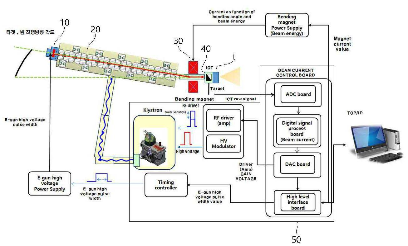
도 1은 본 발명에 따른 의료용 선형가속기의 개념도이다.
도 2는 본 발명에 따른 의료용 선형가속기의 계통도이다.
도 3은 측정부의 구성 및 출력 그래프가 도시된 도면이다.
도 4는 피드백 제어의 개념을 나타낸 블록도이다.
도 5는 본 발명에 따른 의료용 선형가속기의 흐름도이다.
도 6은 전자빔의 에너지 및 전류에 관한 그래프이다. 1 is a conceptual diagram of a medical linear accelerator according to the present invention.
2 is a block diagram of a medical linear accelerator according to the present invention.
3 is a diagram showing the configuration of the measurement section and the output graph.
4 is a block diagram showing the concept of feedback control.
5 is a flowchart of a medical linear accelerator according to the present invention.
6 is a graph relating to the energy and current of the electron beam.
이하, 본 발명의 실시 예에 따른 의료용 선형가속기 및 그 제어방법에 대하여, 첨부된 도면을 참조하여 상세히 설명한다. 그리고 이하의 실시예의 설명에서 각각의 구성요소의 명칭은 당업계에서 다른 명칭으로 호칭될 수 있다. 그러나 이들의 기능적 유사성 및 동일성이 있다면 변형된 실시예를 채용하더라도 균등한 구성으로 볼 수 있다. 또한 각각의 구성요소에 부가된 부호는 설명의 편의를 위하여 기재된다. 그러나 이들 부호가 기재된 도면상의 도시 내용이 각각의 구성요소를 도면내의 범위로 한정하지 않는다. 마찬가지로 도면상의 구성을 일부 변형한 실시예가 채용되더라도 기능적 유사성 및 동일성이 있다면 균등한 구성으로 볼 수 있다. 또한 당해 기술분야의 일반적인 기술자 수준에 비추어 보아, 당연히 포함되어야 할 구성요소로 인정되는 경우 이에 대하여는 설명을 생략한다.Hereinafter, a medical linear accelerator and a control method thereof according to an embodiment of the present invention will be described in detail with reference to the accompanying drawings. In the following description of the embodiments, the names of the respective components may be referred to as other names in the art. However, if there is a functional similarity and an equivalence thereof, the modified structure can be regarded as an equivalent structure. In addition, reference numerals added to respective components are described for convenience of explanation. However, the contents of the drawings in the drawings in which these symbols are described do not limit the respective components to the ranges within the drawings. Likewise, even if the embodiment in which the structure on the drawing is partially modified is employed, it can be regarded as an equivalent structure if there is functional similarity and uniformity. Further, in view of the level of ordinary skill in the art, if a component is considered to be included as a matter of course, a description thereof will be omitted.
도 1은 본 발명에 따른 의료용 선형가속기의 개념도이며, 도 2는 본 발명에 따른 의료용 선형가속기의 계통도이다.FIG. 1 is a conceptual diagram of a medical linear accelerator according to the present invention, and FIG. 2 is a schematic diagram of a medical linear accelerator according to the present invention.
도시된 바와 같이, 본 발명에 따른 의료용 선형 가속기는 전자 총(10), 클라이스트론(Klystron), 마그네틱 필터(30), 제어부(50), 타겟(t)을 포함하여 구성될 수 있다.As shown, the medical linear accelerator according to the present invention may include an
전자 총(10)은 초기 전자빔을 방출하도록 구성된다. 전자빔은 캐소드를 포함하여 구성되며, 캐소드에 고전압이 인가되어 열전자를 방출하게 된다. 열전자 방출에 의한 전자빔은 캐소드 표면에서 수 eV의 낮은 에너지를 갖게 되며, 초기에 낮은 에너지의 열전자들은 캐소드 표면을 따라 다양한 각도로 방출되며, 전자 총(10)에 인가되는 전기장 방향에 의해 직진성을 가질 수 있게 된다. 전자 총(10)은 이극관 또는 삼극관 타입으로 적용될 수 있다. 또한 전자 총(10)을 구성하는 플랜지, 필라멘트 등 다양한 구성요소가 포함될 수 있다. 이때 전자 총(10)에 고전압을 발생시킬 수 있도록 고전압 파워발생부가 별도로 구비되며, 전자 총(10)은 고전압 파워발생부와 연결될 수 있다.The
가속관(20)은 전자 총(10)으로부터 방출된 전자를 가속하기 위해 구성된다. 가속관(20)은 클라이스트론으로 구성될 수 있으며, 선형으로 가속될 수 있도록 직선형으로 구성될 수 있다. 전자빔은 가속관(20) 내부에 형성된 진공 챔버를 통과하면서 RF전계에 의해 가속된다. 이때, 전자빔은 클라이스트론에서 가속되어 수 MeV 이상의 에너지를 갖도록 가속될 수 있다. The accelerating
마그네틱 필터(30)는 가속된 전자 빔 중 일부를 필터링할 수 있도록 구성된다. 마그네틱 필터(30)의 주축의 위치는 가속관(20)에서의 전자빔의 경로와 소정각도로 이루어 배치되도록 구성된다. 따라서 전자 빔의 에너지와 마그네틱 필터(30)의 자기장의 세기에 따라 마그네틱 필터(30)를 통과하여 타겟에 도달되는지 여부가 결정된다. 즉 전자빔의 최종 조사 진행방향과 선형 가속관(20)의 각도 차이를 보상할 수 있도록 구성된다. 한편, 마그네틱 필터(30)는 마그네틱 필드(magnetic field) 조정용 파워 서플라이로부터 전력을 공급받을 수 있다.The
전술한 전자 총(10), 클라이스트론, 마그네틱 필터(30)는 후술할 제어부(50)에 의하여 출력이 조절되도록 구성될 수 있다. 다만, 전술한 전자 총(10), 클라이스트론, 마그네틱 필터(30)는 널리 사용되고 있는 구성이므로 그 구성 및 기능에 대한 더 이상의 상세한 설명은 생략하도록 한다.The
측정부(40)는 가속관(20) 및 마그네틱 필터(30)를 통과한 전자빔의 전류를 측정할 수 있도록 구성된다. 측정부(40)는 전류의 손실을 최소화할 수 있도록 비접촉 방식으로 빔 전류를 측정하게 된다. 빔의 경로상에 인접하여 유도된 유도기전력을 측정하여 피드백 할 수 있도록 구성된다. 한편, 이러한 측정부(40)의 구성 및 기능에 대하여는 차후 도 3을 참조하여 상세히 설명하도록 한다.The
제어부(50)는 전자 총(10), 가속관(20), 마그네틱 필터(30)를 포함한 의료용 선형가속기의 구성요소를 구동 및 제어할 수 있도록 구성된다. 구체적으로 각각의 구성요소를 구동에 필요한 드라이버, 모듈레이터, 제너레이터 등을 제어하도록 프로세서, DAC (digital to analog converter) 및 ADC (analog to digital conveter)를 포함하여 구성될 수 있다.The
제어부(50)는 전자 총(10)의 빔 전류를 조절할 수 있도록 전자 총(10)에 연결된 고전압 파워발생부를 제어하도록 구성될 수 있다. 전자 방출시 전자 총(10)에 인가되는 고전압 펄스파의 펄스폭을 조절하여 전자 빔의 전류를 제어할 수 있게 된다. 이때, 전술한 측정부(40)로부터 측정된 값을 이용하여 제어가 이루어질 수 있다. The
제어부(50)는 또한 가속관(20)의 출력과 관련하여 RF 드라이버, 고전압 모듈레이터를 포함한 관련 구성요소를 제어할 수 있다. 가속관(20)의 출력에 따라 전자 빔의 에너지를 조절할 수 있게 된다.The
타겟은 최종적으로 전자빔이 도달하여 핵반응을 일으키거나 특정 파장의 에너지를 얻을 수 있도록 구성된다. 한편 이러한 타겟은 다양하게 변형되어 적용이 가능하므로 더 이상의 상세한 설명은 생략하도록 한다.The target is ultimately configured to reach the electron beam to cause a nuclear reaction or to obtain energy of a specific wavelength. Meanwhile, since such a target can be variously modified and applied, detailed description will be omitted.
이하에서는 도 3 및 도 4를 참조하여 측정부(40)와 제어부(50)의 기능에 대하여 상세히 설명하도록 한다.Hereinafter, the functions of the measuring
도 3은 측정부(40)의 구성 및 출력 그래프가 도시된 도면이다. 도시된 바와 같이, 측정부(40)는 빔의 경로 주변에서 전자 빔의 이동에 의한 유도기전력을 측정할 수 있도록 구성된다. 측정부(40)로 구성되는 일 예로서 ICT(Integrating Current Transformer)가 될 수 있다. ICT는 유도기전력을 측정하는 회로로 구성되어 펄스파의 입력에 따른 출력이 이루어질 수 있도록 구성될 수 있다. 이때 측정부(40)의 출력인 측정값은 다음의 식에 의해 결정될 수 있다.3 is a diagram showing a configuration and an output graph of the measuring

이를 통해 전자 빔의 이동에 따른 펄스파 형태의 입력이 낮은 피크 값과 낮은 변화량을 갖는 펄스파의 형태로 변환되어 출력된다. 이와 같이 비 접촉식으로 전자 빔의 전류 값을 측정하게 되면, 전자 빔의 손실을 극소화 시키며 무손실에 가깝게 측정 가능하므로 정밀한 제어가 가능하게 된다.In this way, the input of the pulse wave shape according to the movement of the electron beam is converted into the pulse wave shape having the low peak value and the low change amount and outputted. When the current value of the electron beam is measured in the non-contact manner as described above, the loss of the electron beam can be minimized and the measurement can be performed close to losslessness, thereby enabling precise control.
도 4 는 피드백 제어의 개념을 나타낸 블록도이다. 도시된 바와 같이, 제어부(50)는 ADC(analog to digital converter) 보드 및 DAC(digital to analog converter) 보드를 포함하며, 디지털 제어를 위한 프로세서 및 레퍼런스 부를 포함하여 구성될 수 있다.4 is a block diagram showing the concept of feedback control. As shown, the
ADC 보드는 ICT로부터 측정된 값을 입력받고, 이중 피크값(peak)을 읽는 피크 디텍터(peak detector)의 전압값을 디지털 신호로 변화시키게 된다.The ADC board receives the measured value from the ICT and changes the voltage value of the peak detector reading the double peak value into a digital signal.
프로세서는 ADC 보드로부터 피드백 값을 수신하고, 레퍼런스 부에 저장된 데이터와 비교하여 현재 빔 전류를 연산하게 된다. 레퍼런스 부에는 ICT의 출력값에 대응하는 빔 전류 데이터가 포함되어 있다. 이때 제어부(50)는 사용자가 원하는 빔의 전류값인 기준입력과 레퍼런스 부로부터 로딩한 현재 빔 전류값을 비교한 뒤 전자 총(10)의 펄스 조절량을 결정하게 된다.The processor receives the feedback value from the ADC board and compares it with the data stored in the reference section to compute the current beam current. The reference section includes beam current data corresponding to the output value of the ICT. At this time, the
제어부(50)는 추가로 마그네틱 필터(30)의 필터링을 조절할 수 있도록 마그넷 전원공급부의 출력을 조절하는 신호를 발생시킨다. 이러한 신호에 의해 마그네틱 필터(30)를 조절하는 High Level Interface Board가 마그넷 전원 공급부의 출력을 조절하게 된다. 이때 제어부(50)는 마그네틱 필터(30)의 전류값 캘리브레이션 테이블에 저장되어 있는 데이터와 매칭시켜 필터링을 위한 출력값을 조절하도록 구성한다.The
제어부(50)는 가속관(20)의 제어를 위하여 RF 드라이버의 출력을 조절할 수 있도록 프로세서의 출력값을 Amp Gain의 전압 값으로 변화시키게 된다. 이때 전술한 DAC 보드가 적용될 수 있다. 결국, RF 드라이버의 출력값이 조절되면 빔의 에너지를 변화시킬 수 있게 된다.The
이때 프로세서는 최종적으로 원하는 에너지 및 전류 값을 갖는 전자 빔을 생성할 수 있도록 전자 총(10)과 가속관(20)을 동시에 제어하도록 구성된다. 즉 전자 총(10)의 펄스 값을 조절하고 가속관(20)에 적용되는 RF 드라이버의 이득 값을 동시에 제어하게 된다.At this time, the processor is configured to simultaneously control the
한편, 본 발명은 전류를 측정하고 전자 빔의 전류 및 에너지를 제어할 수 있으나, 다양한 값으로 변화되어 적용이 가능하므로, 상세한 수치의 기재는 생략하도록 한다.Meanwhile, the present invention can measure the current and control the current and energy of the electron beam, but it can be applied to a variety of values, so detailed description of the numerical values is omitted.
이상에서 설명한 바와 같이, 본 발명에 따른 의료용 선형가속기는 전자 빔의 전류와 에너지를 동시에 제어할 수 있어 제품의 신뢰도 및 정확도가 향상되는 효과가 있다.As described above, the medical linear accelerator according to the present invention can simultaneously control the current and the energy of the electron beam, thereby improving the reliability and accuracy of the product.
이하에서는 도 5 및 도 6을 참조하여 본 발명에 따른 의료용 선형가속기의 제어방법에 대하여 도 5를 참조하여 설명하기로 한다. Hereinafter, a method of controlling the medical linear accelerator according to the present invention will be described with reference to FIG. 5, with reference to FIGS. 5 and 6. FIG.
도 5는 본 발명에 따른 의료용 선형가속기의 흐름도이다. 도시된 바와 같이, 본 발명에 따른 의료용 선형가속기는 준비단계(S100), 전자 빔을 조사하는 단계(S200), 전자 빔을 가속하는 단계(S300), 전자 빔의 전류를 측정하는 단계(S400), 및 측정된 전류값을 피드백하여 전자 빔의 펄스 및 가속량을 조절하는 단계(S500)를 포함하여 구성될 수 있다.5 is a flowchart of a medical linear accelerator according to the present invention. As shown, the medical linear accelerator according to the present invention includes a preparing step S100, a step S200 of irradiating the electron beam, a step S300 of accelerating the electron beam, a step S400 of measuring the current of the electron beam, , And adjusting the pulse and the acceleration amount of the electron beam by feeding back the measured current value (S500).
준비단계(S100)는 장치를 작동하기 전 각 구성요소를 동작상태로 세팅하는단계에 해당한다. 준비단계는 벤딩 마그넷 전류 인가 단계, 빔 펄스 폭 설정 단계를 포함하여 구성될 수 있다. 벤딩 마그넷 전류 인가 단계는 특정 에너지를 갖는 빔을 필터링할 수 있도록 전자 총의 작동 전 벤딩 마그넷에 적절한 자기장을 형성시키는 단계에 해당한다. 빔 펄스 폭 설정 단계는 전자 총에서 인가되는 전자 빔이 특정 전류값을 가질 수 있도록 펄스 폭을 절성하는 단계이다.The preparation step S100 corresponds to setting each component to an operating state before operating the device. The preparation step may include a step of applying a bending magnet current, and a step of setting a beam pulse width. The step of applying the bending magnet current corresponds to the step of forming a suitable magnetic field in the bending magnet before operation of the electron gun so as to be able to filter the beam having the specific energy. The step of setting the beam pulse width is a step of subtracting the pulse width so that the electron beam applied from the electron gun has a specific current value.
전자 빔을 조사하는 단계(S200)는 전자 총을 작동시켜 전자 빔을 조사하는 단계에 해당한다. The step of irradiating the electron beam (S200) corresponds to the step of operating the electron gun to irradiate the electron beam.
전자 빔을 가속하는 단계(S300)는 가속관을 통과하는 전자 빔을 RF 에너지를 인가하여 가속시키는 단계에 해당한다.The step of accelerating the electron beam (S300) corresponds to the step of accelerating the electron beam passing through the acceleration tube by applying RF energy.
전자 빔의 전류를 측정하는 단계(S400)는 전자 빔의 전류를 비접촉식 유도기전력으로 측정하는 단계에 해당한다. 이때 빔 전류의 측정은 ICT(Integrating Current Transformer)를 이용하여 수행될 수 있다.The step S400 of measuring the current of the electron beam corresponds to the step of measuring the current of the electron beam by the non-contact induced electromotive force. At this time, measurement of the beam current can be performed using ICT (Integrating Current Transformer).
측정된 전류값을 피드백하여 전자 빔의 펄스 및 가속량을 조절하는 단계(S500)는 전류값을 조절하기 위하여 전자 총 및 가속관을 제어하는 단계에 해당한다. 본 단계는 적정 엠프 게인 전압을 판단하는 단계, 빔 전류의 과부족을 판단하는 단계, 이후 조절 단계를 포함하여 구성될 수 있다.The step S500 of adjusting the pulse and the acceleration amount of the electron beam by feeding back the measured current value corresponds to the step of controlling the electron gun and the acceleration tube to adjust the current value. This step may include a step of determining an appropriate amplifier gain voltage, a step of determining whether the beam current is large or small, and an adjusting step.
적정 엠프 게인 전압을 판단하는 단계(S510)는 엠프 게인 전압이 상하 제한 폭 내의 적정수준으로 형성되었는지를 판단하는 단계이며, 그렇지 않는 경우, 게인 전압을 디폴트 설정하여 준비단계(S100)를 다시 수행한다.Step S510 of determining the appropriate amp gain voltage is a step of determining whether the amp gain voltage is formed at an appropriate level within the upper limit and lower limit. If not, the gain voltage is set default and the preparation step S100 is performed again .
빔 전류의 과부족을 판단하는 단계(S520)는 측정된 빔 전류값을 빔 전류의 설정치, 즉 사용자의 입력에 따른 설정치와 비교하여 과부족을 판단하게 되며, 측정된 전류값이 설정된 전류값보다 높은 경우, 현재의 설정의 변화 없이 의료용 선형가속기를 사용하게 된다. 그러나, 설정된 전류값보다 낮게 측정된 경우, 전류값을 높이기 위하여 엠프의 게인값을 조절하는 조절단계가 수행된다.In step S520, the measured beam current value is compared with the set value of the beam current, that is, the set value according to the input of the user, thereby determining whether the measured current value is greater than the set current value , The medical linear accelerator is used without changing the current setting. However, when the current value is measured to be lower than the set current value, an adjustment step of adjusting the gain value of the amplifier to increase the current value is performed.
도 6은 전자 빔의 에너지와 전류가 나타난 그래프이다. 여기서 현재의 전류값이 측정 되었을 때 전자 빔의 전류값을 상승시키기 위해서는 전자 빔의 에너지를 증가시키거나 감소시켜야 하는데, 이를 한번에 판단할 수 없다. 따라서 에너지를 증가시키는 단계와 감소시키는 단계를 수행하여 측정된 전자 빔의 전류값을 비교하여 증가 경향을 판단하게 된다(S530). 이때, 가속관에 인가되는 RF에너지를 조절하여 전자 빔의 에너지를 증가시켰을 때의 전류 값(Value 1)과 전자 빔의 에너지를 감소시켰을 때의 전류값(Value 2)를 비교하여 전류값이 더 크게 측정된 경향을 갖는 방향으로 RF에너지를 변화(S540)시키게 된다. 6 is a graph showing the energy and current of the electron beam. In order to increase the current value of the electron beam when the current value is measured, it is necessary to increase or decrease the energy of the electron beam. Therefore, increasing and decreasing the energy are performed to compare the current values of the measured electron beams to determine the increasing tendency (S530). At this time, by comparing the current value (Value 1) when the energy of the electron beam is increased by adjusting the RF energy applied to the acceleration tube and the current value (Value 2) when the energy of the electron beam is decreased, The RF energy is changed in a direction having a largely measured tendency (S540).
이상에서 살펴본 바와 같이, 본 발명에 따른 의료용 선형가속기 및 그 제어방법은 전자 빔의 전류를 측정하여 전자빔의 에너지 및 전류값을 동시에 제어할 수 있으므로 정확성을 높일 수 있으며, 의료용 선형가속기의 신뢰도를 높일 수 있는 효과가 있다.As described above, the medical linear accelerator and its control method according to the present invention can increase the accuracy and control the energy and the current value of the electron beam by measuring the current of the electron beam, thereby increasing the reliability of the medical linear accelerator There is an effect that can be.
10: 전자 총
20: 가속관
30: 마그네틱 필터
40: 측정부
50: 제어부
t: 타겟
S100: 준비단계,
S200: 전자 빔을 조사하는 단계,
S300: 전자 빔을 가속하는 단계,
S400: 전자 빔의 전류를 측정하는 단계
S500: 측정된 전류값을 피드백하여 전자 빔의 펄스 및 가속량을 조절하는 단계
S510: 적정 엠프 게인 전압을 판단하는 단계
S520: 빔 전류의 과부족을 판단하는 단계
S530: 전류 증가 경향을 판단하는 단계
S540: 조절 단계10: Electronic gun
20: Acceleration tube
30: Magnetic filter
40:
50:
t: target
S100: preparation step,
S200: irradiating the electron beam,
S300: Accelerating the electron beam,
S400: Step of measuring the current of the electron beam
S500: adjusting the pulse and acceleration amount of the electron beam by feeding back the measured current value
S510: judging the appropriate amp gain voltage
S520: Judging whether the beam current is large or small
S530: Step of judging the current increase tendency
S540: Adjustment step
Claims (12)
상기 전자 빔을 가속하는 클라이스트론;
이동하는 빔 에너지의 주변에서 발생하는 유도기전력을 측정하도록 구성된 측정부; 및
상기 측정부에서 측정되는 값을 근거로 상기 전자총 및 상기 클라이스트론을 제어하도록 구성된 제어부를 포함하며,
상기 측정부는 상기 전자 빔의 측정을 위한 손실을 최소화 할 수 있도록 ICT(Integrating Current Transformer)를 포함하여 구성되며,
상기 제어부는,
측정된 유도기전력 값에 대응하는 전자 빔의 전류값을 기준출력값과 비교하여 상기 전류값과 상기 기준출력값 사이의 오차를 줄일수 있도록 상기 전자총의 펄스폭을 조절하여 상기 전자빔의 전류를 조절하며,
상기 클라이스트론에 적용되는 RF드라이버를 제어하여 전자빔의 에너지를 조절하며,
상기 전자 빔의 에너지를 증가 또는 감소시켰을 때 각각 측정되는 상기 전자 빔의 전류값을 비교하여 증가경향을 판단하고, 상기 전류를 증가시킬 수 있도록 상기 전자 빔의 에너지를 증가 또는 감소시키도록 조절하는 것을 특징으로 하는 의료용 선형 가속기.An electron gun for irradiating an electron beam;
A klystron accelerating the electron beam;
A measuring unit configured to measure an induced electromotive force generated in the vicinity of moving beam energy; And
And a control unit configured to control the electron gun and the klystron on the basis of a value measured by the measuring unit,
The measuring unit includes an ICT (Integrating Current Transformer) to minimize the loss for the measurement of the electron beam,
Wherein,
Adjusting a pulse width of the electron gun so as to reduce an error between the current value and the reference output value by comparing the current value of the electron beam corresponding to the measured induced electromotive force value with the reference output value,
Controls the RF driver applied to the klystron to control the energy of the electron beam,
Determining the increase tendency by comparing the current values of the electron beams measured when the energy of the electron beam is increased or decreased and adjusting the energy of the electron beam so as to increase the current Characterized by a medical linear accelerator.
가속된 전자 빔 중 목표 에너지 대역의 전자 빔을 필터링하는 마그네틱 필터를 더 포함하며,
상기 측정부는 상기 마그네틱 필터를 통과한 전자 빔에 의한 유도기전력을 측정할 수 있도록 상기 마그네틱 필터 이후의 전자 빔의 경로상에 구비되는 것을 특징으로 하는 의료용 선형 가속기.The method according to claim 1,
Further comprising a magnetic filter for filtering the electron beam in the target energy band of the accelerated electron beam,
Wherein the measurement unit is provided on the path of the electron beam after the magnetic filter so as to measure the induced electromotive force by the electron beam passing through the magnetic filter.
상기 마그네틱 필터는,
특정 에너지를 갖는 전자 빔을 필터링 할 수 있도록 상기 클라이스트론에서의 전자 빔의 경로와 소정각도를 두어 구비되는 것을 특징으로 하는 의료용 선형 가속기.The method of claim 3,
The magnetic filter includes:
Wherein the linear accelerator is provided with a predetermined angle with the path of the electron beam in the klystron so as to filter the electron beam having the specific energy.
클라이스트론에서 상기 전자 빔을 가속하는 단계;
상기 전자 빔의 전류를 측정하는 단계; 및
상기 측정된 전류값을 피드백하여 상기 전자 빔의 펄스 및 에너지를 조절하는 단계를 포함하며,
상기 전자 빔의 전류를 측정하는 단계는 상기 전자 빔의 측정을 위한 손실을 최소화 할 수 있도록 상기 전자 빔의 경로 주변에서 발생되는 유도기전력을 ICT(Integrating Current Transformer)를 이용하여 측정하며,
상기 전자 빔의 펄스 및 에너지를 조절하는 단계는,
상기 전자 빔을 조사하는 전자총의 펄스폭을 조절하며, 상기 클라이스트론의 RF출력값을 조절하여 수행되며,
상기 전자 빔의 에너지를 증가 또는 감소시켰을 때 각각 측정되는 상기 전자 빔의 전류값을 비교하여 증가경향을 판단하고, 상기 전류를 증가시킬 수 있도록 상기 전자 빔의 에너지를 증가 또는 감소시키도록 조절하는 것을 특징으로 하는 의료용 선형가속기의 제어방법.Irradiating an electron beam;
Accelerating the electron beam at a klystron;
Measuring a current of the electron beam; And
And adjusting the pulse and energy of the electron beam by feeding back the measured current value,
The measuring of the current of the electron beam may include measuring an induced electromotive force generated around the path of the electron beam using an ICT (Integrating Current Transformer) so as to minimize a loss for the measurement of the electron beam,
Wherein adjusting the pulse and energy of the electron beam comprises:
Adjusting the pulse width of the electron gun for irradiating the electron beam and adjusting the RF output value of the klystron,
Determining the increase tendency by comparing the current values of the electron beams measured when the energy of the electron beam is increased or decreased and adjusting the energy of the electron beam so as to increase the current Wherein the linear accelerator is a linear accelerator.
상기 전자 빔의 가속 이후 상기 빔을 파장에 따라 필터링하는 단계를 더 포함하는 것을 특징으로 하는 의료용 선형가속기의 제어방법.9. The method of claim 8,
Further comprising the step of filtering the beam according to the wavelength after acceleration of the electron beam.
Priority Applications (1)
| Application Number | Priority Date | Filing Date | Title |
|---|---|---|---|
| KR1020170028431A KR101930363B1 (en) | 2017-03-06 | 2017-03-06 | The apparatus of medical linear accelerator and the method of that |
Applications Claiming Priority (1)
| Application Number | Priority Date | Filing Date | Title |
|---|---|---|---|
| KR1020170028431A KR101930363B1 (en) | 2017-03-06 | 2017-03-06 | The apparatus of medical linear accelerator and the method of that |
Publications (2)
| Publication Number | Publication Date |
|---|---|
| KR20180101897A KR20180101897A (en) | 2018-09-14 |
| KR101930363B1 true KR101930363B1 (en) | 2018-12-18 |
Family
ID=63599667
Family Applications (1)
| Application Number | Title | Priority Date | Filing Date |
|---|---|---|---|
| KR1020170028431A Expired - Fee Related KR101930363B1 (en) | 2017-03-06 | 2017-03-06 | The apparatus of medical linear accelerator and the method of that |
Country Status (1)
| Country | Link |
|---|---|
| KR (1) | KR101930363B1 (en) |
Families Citing this family (2)
| Publication number | Priority date | Publication date | Assignee | Title |
|---|---|---|---|---|
| CN111068189B (en) * | 2019-11-27 | 2025-03-11 | 广东清大创新研究院有限公司 | A medical accelerator, a dose monitoring system and a dose monitoring method thereof |
| CN115882327B (en) * | 2021-09-26 | 2025-11-11 | 中国科学院大连化学物理研究所 | Hundred femtosecond pulse length free electron laser generating device and method based on electron beam cutting |
Citations (1)
| Publication number | Priority date | Publication date | Assignee | Title |
|---|---|---|---|---|
| JP2002237399A (en) * | 2001-02-09 | 2002-08-23 | Mitsubishi Electric Corp | Electron beam accelerator and electron beam acceleration method |
Family Cites Families (1)
| Publication number | Priority date | Publication date | Assignee | Title |
|---|---|---|---|---|
| US20080043910A1 (en) | 2006-08-15 | 2008-02-21 | Tomotherapy Incorporated | Method and apparatus for stabilizing an energy source in a radiation delivery device |
-
2017
- 2017-03-06 KR KR1020170028431A patent/KR101930363B1/en not_active Expired - Fee Related
Patent Citations (1)
| Publication number | Priority date | Publication date | Assignee | Title |
|---|---|---|---|---|
| JP2002237399A (en) * | 2001-02-09 | 2002-08-23 | Mitsubishi Electric Corp | Electron beam accelerator and electron beam acceleration method |
Also Published As
| Publication number | Publication date |
|---|---|
| KR20180101897A (en) | 2018-09-14 |
Similar Documents
| Publication | Publication Date | Title |
|---|---|---|
| US20250203745A1 (en) | Linear accelerator system for stable pulsing at multiple dose levels | |
| EP3111732B1 (en) | Linear accelerator system and method with stable interleaved and intermittent pulsing | |
| JP3912364B2 (en) | Particle beam therapy system | |
| KR102620676B1 (en) | Automatic control apparatus and method for resonant frequency matching of linear electron accelerator for magnetron-based radiation therapy | |
| JP4646069B2 (en) | Particle beam irradiation system | |
| WO1995008909A1 (en) | Accelerator operation method, accelerator, and accelerator system | |
| JP6257751B2 (en) | Particle beam irradiation equipment | |
| US11083074B2 (en) | Scanning linear accelerator system having stable pulsing at multiple energies and doses | |
| JP5159688B2 (en) | Particle beam therapy system | |
| KR101930363B1 (en) | The apparatus of medical linear accelerator and the method of that | |
| US20250287492A1 (en) | Scanning linear accelerator system for producing x-rays at controlled dose and repetition rates | |
| KR102713844B1 (en) | Linear accelerator with enhanced pulse synchronization function | |
| JP6007133B2 (en) | Synchrotron and particle beam therapy system using the same | |
| KR102407598B1 (en) | Grid pulse control apparatus and method, linear accelerator using the apparatus | |
| KR20240066553A (en) | Precise Automatic Control Method of Linear Accelerator System | |
| KR101890329B1 (en) | Optimization of the beam current in a linear accelerator by adjusting RF timing | |
| CN107153367B (en) | Method and apparatus for controlling output frequency of radio frequency source | |
| CN114466500B (en) | Closed loop control of an X-ray pulse train generated by means of a linac system | |
| KR20230068632A (en) | Linear accelerator with precise radiation dose control function | |
| CN119480574A (en) | Electron beam current control method, circuit and control system | |
| JP2017143017A (en) | Particle accelerator system and particle beam therapy system with the same | |
| JPH04319300A (en) | High frequency accelerating device for accelerator | |
| JP2006216568A (en) | Ion source |
Legal Events
| Date | Code | Title | Description |
|---|---|---|---|
| A201 | Request for examination | ||
| PA0109 | Patent application |
St.27 status event code: A-0-1-A10-A12-nap-PA0109 |
|
| PA0201 | Request for examination |
St.27 status event code: A-1-2-D10-D11-exm-PA0201 |
|
| D13-X000 | Search requested |
St.27 status event code: A-1-2-D10-D13-srh-X000 |
|
| D14-X000 | Search report completed |
St.27 status event code: A-1-2-D10-D14-srh-X000 |
|
| E902 | Notification of reason for refusal | ||
| PE0902 | Notice of grounds for rejection |
St.27 status event code: A-1-2-D10-D21-exm-PE0902 |
|
| AMND | Amendment | ||
| E13-X000 | Pre-grant limitation requested |
St.27 status event code: A-2-3-E10-E13-lim-X000 |
|
| P11-X000 | Amendment of application requested |
St.27 status event code: A-2-2-P10-P11-nap-X000 |
|
| P13-X000 | Application amended |
St.27 status event code: A-2-2-P10-P13-nap-X000 |
|
| PG1501 | Laying open of application |
St.27 status event code: A-1-1-Q10-Q12-nap-PG1501 |
|
| E601 | Decision to refuse application | ||
| PE0601 | Decision on rejection of patent |
St.27 status event code: N-2-6-B10-B15-exm-PE0601 |
|
| AMND | Amendment | ||
| E13-X000 | Pre-grant limitation requested |
St.27 status event code: A-2-3-E10-E13-lim-X000 |
|
| P11-X000 | Amendment of application requested |
St.27 status event code: A-2-2-P10-P11-nap-X000 |
|
| P13-X000 | Application amended |
St.27 status event code: A-2-2-P10-P13-nap-X000 |
|
| PX0901 | Re-examination |
St.27 status event code: A-2-3-E10-E12-rex-PX0901 |
|
| PX0701 | Decision of registration after re-examination |
St.27 status event code: A-3-4-F10-F13-rex-PX0701 |
|
| X701 | Decision to grant (after re-examination) | ||
| GRNT | Written decision to grant | ||
| PR0701 | Registration of establishment |
St.27 status event code: A-2-4-F10-F11-exm-PR0701 |
|
| PR1002 | Payment of registration fee |
Fee payment year number: 1 St.27 status event code: A-2-2-U10-U11-oth-PR1002 |
|
| PG1601 | Publication of registration |
St.27 status event code: A-4-4-Q10-Q13-nap-PG1601 |
|
| PR1001 | Payment of annual fee |
Fee payment year number: 4 St.27 status event code: A-4-4-U10-U11-oth-PR1001 |
|
| PR1001 | Payment of annual fee |
Fee payment year number: 5 St.27 status event code: A-4-4-U10-U11-oth-PR1001 |
|
| PC1903 | Unpaid annual fee |
Not in force date: 20231213 Payment event data comment text: Termination Category : DEFAULT_OF_REGISTRATION_FEE St.27 status event code: A-4-4-U10-U13-oth-PC1903 |
|
| R18-X000 | Changes to party contact information recorded |
St.27 status event code: A-5-5-R10-R18-oth-X000 |
|
| PN2301 | Change of applicant |
St.27 status event code: A-5-5-R10-R11-asn-PN2301 St.27 status event code: A-5-5-R10-R13-asn-PN2301 |
|
| PC1903 | Unpaid annual fee |
Ip right cessation event data comment text: Termination Category : DEFAULT_OF_REGISTRATION_FEE Not in force date: 20231213 St.27 status event code: N-4-6-H10-H13-oth-PC1903 |
|
| R18-X000 | Changes to party contact information recorded |
St.27 status event code: A-5-5-R10-R18-oth-X000 |