KR101864893B1 - Electromagnetic resonance sensing device using minority channel - Google Patents
Electromagnetic resonance sensing device using minority channel Download PDFInfo
- Publication number
- KR101864893B1 KR101864893B1 KR1020110054033A KR20110054033A KR101864893B1 KR 101864893 B1 KR101864893 B1 KR 101864893B1 KR 1020110054033 A KR1020110054033 A KR 1020110054033A KR 20110054033 A KR20110054033 A KR 20110054033A KR 101864893 B1 KR101864893 B1 KR 101864893B1
- Authority
- KR
- South Korea
- Prior art keywords
- loop
- sub
- induced current
- magnitude
- electromagnetic
- Prior art date
- Legal status (The legal status is an assumption and is not a legal conclusion. Google has not performed a legal analysis and makes no representation as to the accuracy of the status listed.)
- Active
Links
Images


Classifications
-
- G—PHYSICS
- G06—COMPUTING OR CALCULATING; COUNTING
- G06F—ELECTRIC DIGITAL DATA PROCESSING
- G06F3/00—Input arrangements for transferring data to be processed into a form capable of being handled by the computer; Output arrangements for transferring data from processing unit to output unit, e.g. interface arrangements
- G06F3/01—Input arrangements or combined input and output arrangements for interaction between user and computer
- G06F3/03—Arrangements for converting the position or the displacement of a member into a coded form
- G06F3/041—Digitisers, e.g. for touch screens or touch pads, characterised by the transducing means
- G06F3/046—Digitisers, e.g. for touch screens or touch pads, characterised by the transducing means by electromagnetic means
Landscapes
- Engineering & Computer Science (AREA)
- General Engineering & Computer Science (AREA)
- Theoretical Computer Science (AREA)
- Physics & Mathematics (AREA)
- Human Computer Interaction (AREA)
- General Physics & Mathematics (AREA)
- Electromagnetism (AREA)
- Near-Field Transmission Systems (AREA)
- User Interface Of Digital Computer (AREA)
- Electronic Switches (AREA)
Abstract
적어도 하나의 소프트 키를 구비하는 터치 스크린에 내장되는 전자기 센싱 장치가 개시된다. 본 발명에 따른 전자기 센싱 장치는, 적어도 하나의 소프트 키 각각에 대응하는 적어도 하나의 서브 영역을 포함하는 인쇄 회로 기판부, 전자기 센싱 장치의 전자기 센싱을 제어하는, 적어도 하나의 입출력 채널을 포함하는 제어부 및 제어부의 적어도 하나의 입출력 채널 중 하나로부터 연장되어, 인쇄 회로 기판부의 서브 영역 각각에 배치되는 적어도 하나의 서브 루프를 포함하며, 전자기에 의하여 유도되는 유도 전류를 출력하는 루프부를 포함하며, 서브 루프 각각은 전자기에 의하여 각각 상이한 출력값을 출력한다.An electromagnetic sensing device incorporated in a touch screen having at least one soft key is disclosed. An electromagnetic sensing apparatus according to the present invention includes a printed circuit board portion including at least one sub-region corresponding to each of at least one soft key, a control portion including at least one input / output channel for controlling electromagnetic sensing of the electromagnetic sensing device, And a loop portion extending from one of the at least one input / output channel of the control portion and including at least one sub-loop disposed in each sub-region of the printed circuit board portion, the loop portion outputting an induced current induced by the electromagnetic, Each of them outputs different output values by electromagnetic.
Description
본 발명은 적어도 하나의 소프트 키를 구비하는 터치 스크린에 내장되는 전자기 센싱 장치에 관한 것으로, 더욱 상세하게는 전자기 공진(electromagnetic resonance,EMR)을 센싱하여 사용자로부터 외부 입력을 센싱하는 전자기 센싱 장치에 관한 것이다. The present invention relates to an electromagnetic sensing device incorporated in a touch screen having at least one soft key, and more particularly to an electromagnetic sensing device for sensing an electromagnetic resonance (EMR) will be.
근자에 들어, 스마트 폰 또는 터치 스크린과 관련한 시장이 급속도로 성장함으로써, 이와 관련한 연구 또한 활발하게 진행되고 있다. 스마트 폰 또는 터치 스크린과 관련하여 특정한 명령을 입력하기 위하여 사용자는, 사용자 신체의 일부분 또는 EMR 펜을 디스플레이의 특정 위치에 지정하는 방식으로 특정한 명령을 입력하거나 특정한 아이콘을 지정할 수 있다. In recent years, as the market for smart phones or touch screens has grown rapidly, related research has also been actively conducted. In order to enter a specific command in connection with a smart phone or a touch screen, a user may enter a specific command or designate a particular icon in such a manner that a portion of the user's body or an EMR pen is assigned to a specific location on the display.
사용자 신체의 일부분을 통하여 접촉하는 방식은, 정전용량방식(capacitive type)에 의하여 구현될 수 있다. 정전용량방식을 채택하는 터치스크린은 일반적으로 투명 전극 및 콘덴서를 포함한다. 사용자는 신체의 일부분을 터치스크린에 접촉함으로써, 내장된 콘덴서의 공간 또는 면적에 기계적인 변위를 생성시킬 수 있으며, 이에 따라 변경되는 콘덴서의 정전용량에 기초하여 사용자의 신체 일부분에 의한 터치가 센싱될 수 있다. The manner of contact through a portion of the user's body may be implemented by a capacitive type. A touch screen employing a capacitive method generally includes a transparent electrode and a capacitor. The user can create a mechanical displacement in the space or area of the built-in condenser by contacting a portion of the body with the touch screen, and thus the touch by a part of the user's body is sensed based on the capacitance of the condenser to be changed .
한편, 정전용량방식은 사용자가 언제가 터치스크린에 접촉을 수행하여 소정의 압력 또는 변위를 제공하여야 한다는 불편함이 존재하며, 이에 따라 전자기 공진 방식(EMR)과 관련한 연구가 활발히 진행되고 있다.On the other hand, there is an inconvenience that the user must provide a predetermined pressure or displacement by touching the touch screen when the user touches the touch screen. Accordingly, studies on electromagnetic resonance (EMR) have been actively conducted.
EMR 방식은 인쇄회로기판에 루프 코일을 배치하며, 여기에 전류를 도통시켜 전자기파가 발생되게 제어하며, 발생된 전자기파가 EMR 펜에 의하여 흡수될 수 있도록 제어한다. 여기에서, EMR 펜은 콘덴서 및 루프를 포함할 수 있으며, 흡수한 전자기파를 다시 소정의 주파수로 방출할 수 있다. In the EMR system, a loop coil is disposed on a printed circuit board, a current is conducted to control the electromagnetic coil to generate electromagnetic waves, and the generated electromagnetic wave is controlled to be absorbed by the EMR pen. Here, the EMR pen may include a capacitor and a loop, and the absorbed electromagnetic wave can be emitted again at a predetermined frequency.
EMR 펜에 의하여 방출된 전자기파는, 인쇄회로기판의 루프 코일에 의하여 다시 흡수될 수 있으며, 이에 따라 EMR 펜이 터치스크린의 어느 위치에 근접하여 있는지를 판단할 수 있다.The electromagnetic waves emitted by the EMR pen can be absorbed again by the loop coil of the printed circuit board, and thus it can be determined which position of the EMR pen is close to the touch screen.
도 1a 내지 1c는 종래의 EMR 방식을 설명하기 위한 개념도이다.1A to 1C are conceptual diagrams illustrating a conventional EMR scheme.
도 1a은, 종래의 EMR 방식을 채택한 전자기 센싱 장치를 포함하는 통신 기기(100)의 개념도이다. 도 1a에 도시된 바와 같이, 통신 기기는 디스플레이 화면(110) 및 소프트 키(120)를 포함할 수 있다. 1A is a conceptual diagram of a
여기에서, 디스플레이 화면(110)은 사용자가 인식할 수 있는 시각적 정보를 디스플레이하는 영역일 수 있으며, EMR 방식 또는 정전용량방식을 채택할 수 있다. Here, the
한편, 소프트 키(120)는, 되돌리기, 실행취소, 메뉴화면 표시 제어 등과 같은 기본적인 기능을 사용자가 직관적으로 수행할 수 있도록, 디스플레이 화면(110)과 별도로 제공되는 사용자 인터페이스의 일종이다. 종래의 소프트 키(120)는, 투명 전극 하부에 배치되는 정전용량방식 센서 및 전자기 공진 센서의 격납의 한계에 의하여, 정전용량방식만을 채택하고 있으며, 전자기 공진 센서가 내장된 소프트 키(120)에 대하여서는 아직 개시된 바가 없다. On the other hand, the
도 1b는, 도 1a에 의한 디스플레이 화면(110) 내에 배치된 복수 개의 루프(131,132,133,134)를 나타내는 개념도이다. 도 1b에 도시된 바와 같이, 복수 개의 루프(131,132,133,134)는 서로 겹쳐지도록 배치될 수 있다. 사용자가 특정한 부분 근처에 EMR 펜을 근접시키면, 복수 개의 루프(131,132,133,134)는 EMR 펜으로부터 발생되는 전자기를 센싱할 수 있다.FIG. 1B is a conceptual diagram showing a plurality of
도 1c에 도시된 바와 같이, 복수 개의 루프(131,132,133,134) 각각은 센싱된 전자기에 의하여 유도된 유도 전류를 출력할 수 있다. 복수 개의 루프(131,132,133,134) 중 EMR 펜에 근접한 루프일수록, 진폭이 큰 전자기파를 센싱하여 이에 대응하는 유도 전류를 방출할 수 있으며, 이에 따라 도 1c와 같이 다양한 크기의 유도 전류를 출력할 수 있다.As shown in FIG. 1C, each of the plurality of
통신 기기(100)에 내장된 마이크로프로세서는, 유도 전류 크기의 출력 결과를 인터폴레이션(interpolation)하여, 피크점을 판단할 수 있으며, 이에 따라 사용자 입력 디스플레이 영역을 판단할 수 있다.The microprocessor incorporated in the
한편, 상술한 바와 같이, 소프트 키(120)에 대하여서는 정전용량방식만이 채택이 되기 때문에, 소프트 키(120)에 대하여서는 사용자가 매번 신체의 일부분을 접촉하여 명령을 입력하여야 한다는 불편함이 존재한다.On the other hand, as described above, since only the electrostatic capacity type is adopted for the
또한, 소프트 키(120)에 대하여서도, EMR을 센싱할 수 있도록 별도의 채널을 부가한다면, 채널 및 코일 수가 증가하는 문제점이 발생한다. 이에 따라 제어회로의 크기가 증가하며, 제어회로 및 코일의 증가에 따른 비용이 증가한다는 문제점이 야기된다. Also, if a separate channel is added to the
본 발명은 상술한 문제점을 해결하기 위하여 안출된 것으로, 본 발명은 소프트 키 영역에 배치되는 코일이 소수의 제어회로 채널을 사용할 수 있는 터치스크린에 내장되는 전자기 센싱 장치를 제공한다. SUMMARY OF THE INVENTION The present invention has been made in order to solve the above problems, and it is an object of the present invention to provide an electromagnetic sensing apparatus in which a coil disposed in a soft key region is embedded in a touch screen on which a small number of control circuit channels can be used.
상술한 바를 달성하기 위하여, 본 발명의 일 실시 예에 의한 적어도 하나의 소프트 키를 구비하는 터치 스크린에 내장되는 전자기 센싱 장치는, 상기 적어도 하나의 소프트 키 각각에 대응하는 적어도 하나의 서브 영역을 포함하는 인쇄 회로 기판부, 상기 전자기 센싱 장치의 전자기 센싱을 제어하는, 적어도 하나의 입출력 채널을 포함하는 제어부 및 상기 제어부의 상기 적어도 하나의 입출력 채널 중 하나로부터 연장되어, 상기 인쇄 회로 기판부의 상기 서브 영역 각각에 배치되는 적어도 하나의 서브 루프를 포함하며, 상기 전자기에 의하여 유도되는 유도 전류를 출력하는 루프부를 포함하며, 상기 서브 루프 각각은 상기 전자기에 의하여 각각 상이한 출력값을 출력할 수 있다.In order to accomplish the foregoing, an electromagnetic sensing apparatus built in a touch screen having at least one soft key according to an embodiment of the present invention includes at least one sub-area corresponding to each of the at least one soft keys A control section including at least one input / output channel for controlling electromagnetic sensing of the electromagnetic sensing device, and a control section extending from one of the at least one input / output channel of the control section, And a loop unit outputting an induced current induced by the electromagnetic wave, wherein each of the sub loops can output a different output value by the electromagnetic wave.
한편, 본 발명의 다른 실시 예에 의한 적어도 하나의 소프트 키를 구비하는 터치 스크린에 내장되는 전자기 센싱 장치는, 상기 적어도 하나의 소프트 키 각각에 대응하는 적어도 하나의 서브 영역을 포함하는 인쇄 회로 기판부, 상기 전자기 센싱 장치의 전자기 센싱을 제어하는, 제 1 입출력 채널 및 제 제 2 입출력 채널을 포함하는 제어부, 상기 제 1 입출력 채널로부터 연장되어, 상기 적어도 하나의 서브 영역에 배치되는 적어도 하나의 제 1 서브 루프를 포함하며, 센싱되는 상기 전자기에 의하여 유도된 제 1 유도 전류를 출력하는 제 1 루프부 및 상기 제 2 입출력 채널로부터 연장되어, 상기 적어도 하나의 서브 영역에 배치되는 적어도 하나의 제 2 서브 루프를 포함하며, 센싱되는 상기 전자기에 의하여 유도된 제 2 유도 전류를 출력하는 제 2 루프부를 포함할 수 있다.Meanwhile, an electromagnetic sensing apparatus built in a touch screen having at least one soft key according to another exemplary embodiment of the present invention includes a printed circuit board including at least one sub-area corresponding to each of the at least one soft keys, A control unit including a first input / output channel and a second input / output channel for controlling electromagnetic sensing of the electromagnetic sensing device, a control unit extending from the first input / output channel and arranged in the at least one subarea, A first loop portion including a sub-loop and outputting a first induced current induced by the electromagnetic to be sensed, and a second loop portion extending from the second input / output channel and having at least one second sub- And a second loop unit including a loop and outputting a second induced current induced by the electromagnetic to be sensed .
한편, 본 발명의 또 다른 실시 예에 의한 적어도 하나의 소프트 키를 구비하는 터치 스크린에 내장되는 전자기 센싱 장치는, 상기 적어도 하나의 소프트 키 각각에 대응하는 적어도 하나의 서브 영역을 포함하는 인쇄 회로 기판부, 상기 전자기 센싱 장치의 전자기 센싱을 제어하는, 제 1 입출력 채널, 제 제 2 입출력 채널 및 제 3 입출력 채널을 포함하는 제어부, 상기 제 1 입출력 채널로부터 연장되어, 상기 적어도 하나의 서브 영역 중 일부에 배치되는 적어도 하나의 제 1 서브 루프를 포함하며, 센싱되는 상기 전자기에 의하여 유도된 제 1 유도 전류를 출력하는 제 1 루프부, 상기 제 2 입출력 채널로부터 연장되어, 상기 적어도 하나의 서브 영역 중 일부에 배치되는 적어도 하나의 제 2 서브 루프를 포함하며, 센싱되는 상기 전자기에 의하여 유도된 제 2 유도 전류를 출력하는 제 2 루프부 및 상기 제 3 입출력 채널로부터 연장되어, 상기 적어도 하나의 서브 영역 중 일부에 배치되는 적어도 하나의 제 3 서브 루프를 포함하며, 센싱되는 상기 전자기에 의하여 유도된 제 3 유도 전류를 출력하는 제 3 루프부를 포함할 수 있다.According to another aspect of the present invention, there is provided an electromagnetic sensing apparatus built in a touch screen including at least one soft key, the at least one soft key including at least one sub- A control unit including a first input / output channel, a second input / output channel, and a third input / output channel for controlling electromagnetic sensing of the electromagnetic sensing device, a control unit extending from the first input / output channel, A first loop portion including at least one first sub-loop disposed in the first input / output channel and outputting a first inductive current induced by the electromagnetic to be sensed, a second loop portion extending from the second input / And at least one second sub-loop disposed at a portion of the first sub-loop, wherein the second sub- And at least one third sub-loop extending from the third input / output channel and disposed in a portion of the at least one sub-region, wherein at least one third sub- And a third loop portion for outputting the three-induction current.
본 발명의 다양한 실시 예에 따라서, 소프트 키 영역에 배치되는 코일이 소수의 제어회로 채널을 사용할 수 있는 터치스크린에 내장되는 전자기 센싱 장치가 제공될 수 있다. 이에 따라, 제어회로에서 요구되는 채널의 수가 감소할 수 있어, 제어회로의 크기 및 코일의 수를 감소시킬 수 있다. According to various embodiments of the present invention, an electromagnetic sensing device may be provided in which a coil disposed in a soft key area is embedded in a touch screen that can use a small number of control circuit channels. As a result, the number of channels required in the control circuit can be reduced, and the size of the control circuit and the number of coils can be reduced.
도 1a은 종래의 EMR 방식을 채택한 전자기 센싱 장치를 포함하는 통신 기기의 개념도이다.
도 1b는 도 1a에 의한 디스플레이 화면 내에 배치된 복수 개의 루프를 나타내는 개념도이다.
도 1c는 복수 개의 루프 각각으로부터 출력되는 유도 전류에 대한 그래프이다.
도 2a는 본 발명의 실시 예에 따른 전자기 센싱 장치를 포함하는 터치스크린을 채택하는 통신 기기의 개념도이다.
도 2b는, 도 2a에 의한 통신 기기의 내부에 포함되는 전자기 센싱 장치의 개념도이다.
도 3은 본 발명의 일 실시 예에 따른, 루프부가 인쇄 회로 기판 상에 배치되는 형태를 나타내는 개념도이다.
도 4는 본 발명의 다른 실시 예에 따른, 루프부가 인쇄 회로 기판 상에 배치되는 형태를 나타내는 개념도이다.
도 5a 및 5b는 본 발명의 실시 예에 따른 전자기 유도를 위한 전류를 도통하는 구성 및 유도 전류를 도통하는 구성을 설명하기 위한 개념도이다.
도 6a는 본 발명의 다른 실시 예에 따른 두 개의 입출력 채널을 이용하여, 사용자 지정 서브 루프를 결정하는 것을 설명하기 위한 개념도이다.
도 6b는 본 발명의 다른 실시 예에 따른 두 개의 입출력 채널을 이용하여, 사용자 지정 서브 루프를 결정하는 것을 설명하기 위한 개념도이다.
도 7은 본 발명의 또 다른 실시 예에 따른 두 개의 입출력 채널을 이용하여, 사용자 지정 소프트 키를 판단하는 것을 설명하기 위한 개념도이다.
도 8은 본 발명의 다른 실시 예에 따른 세 개의 채널을 이용하는 전자기 센싱 장치의 개념도이다.
도 9는 본 발명의 또 다른 실시 예에 따른 3개의 입출력 채널(901,902,903)을 이용하는 전자기 센싱 장치의 개념도이다.1A is a conceptual diagram of a communication device including an electromagnetic sensing device employing a conventional EMR scheme.
FIG. 1B is a conceptual diagram showing a plurality of loops arranged in a display screen according to FIG. 1A.
1C is a graph of induced currents output from each of a plurality of loops.
2A is a conceptual diagram of a communication device employing a touch screen including an electromagnetic sensing device according to an embodiment of the present invention.
FIG. 2B is a conceptual diagram of an electromagnetic sensing device included in the communication device according to FIG. 2A.
Fig. 3 is a conceptual diagram showing a configuration in which a loop portion is disposed on a printed circuit board, according to an embodiment of the present invention.
4 is a conceptual diagram showing a form in which a loop portion is disposed on a printed circuit board, according to another embodiment of the present invention.
5A and 5B are conceptual diagrams for explaining a configuration for conducting current for electromagnetic induction and a configuration for conducting induction current according to an embodiment of the present invention.
6A is a conceptual diagram for explaining the determination of a user-specified sub-loop using two input / output channels according to another embodiment of the present invention.
FIG. 6B is a conceptual diagram for explaining the determination of a user-specified sub-loop using two input / output channels according to another embodiment of the present invention.
FIG. 7 is a conceptual diagram for explaining a determination of a user-specified soft key using two input / output channels according to another embodiment of the present invention.
8 is a conceptual diagram of an electromagnetic sensing apparatus using three channels according to another embodiment of the present invention.
9 is a conceptual diagram of an electromagnetic sensing device using three input /
이하에서는, 본 발명의 바람직한 실시 예를 첨부한 도면을 참조하여 더욱 상세하게 설명하도록 한다. 도면들 중 동일한 구성 요소들은 가능한 한 어느 곳에서든지 동일한 부호들로 나타내고 있음에 유의하여야 한다. 하기 설명 및 첨부 도면에서 본 발명의 요지를 불필요하게 흐릴 수 있는 공지 기능 및 구성에 대한 상세한 설명은 생략한다. Hereinafter, preferred embodiments of the present invention will be described in more detail with reference to the accompanying drawings. It is to be noted that the same components in the drawings are denoted by the same reference numerals whenever possible. In the following description and drawings, detailed description of known functions and configurations incorporated herein will be omitted when it may make the subject matter of the present invention unnecessarily obscure.
도 2a는 본 발명의 실시 예에 따른 전자기 센싱 장치를 포함하는 터치스크린을 채택하는 통신 기기(200)의 개념도이다. 도 2a에 도시된 바와 같이, 본 발명의 실시 예에 따른 전자기 센싱 장치를 포함하는 터치스크린을 채택하는 통신 기기(200)는 소프트 키(240)를 포함한다.2A is a conceptual diagram of a
소프트 키(240)는, 되돌리기, 실행취소, 메뉴화면 표시 제어 등과 같은 기본적인 기능을 사용자가 직관적으로 수행할 수 있도록, 디스플레이 화면과 별도로 제공되는 사용자 인터페이스의 일종으로, EMR 방식 또는 정전용량방식을 채택할 수 있다.The
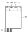
도 2b는, 도 2a에 의한 통신 기기(200)의 내부에 포함되는 전자기 센싱 장치의 개념도이다. 도 2b에 도시된 바와 같이, 전자기 센싱 장치는 도 2a의 소프트 키(240) 각각에 대응하는 적어도 하나의 서브 영역(251,252,253,254)을 포함하는 인쇄 회로 기판부(250)를 포함할 수 있다. 본 실시 예는, 4개의 소프트 키(250)를 포함하는 통신 기기(200)에 관한 것으로, 각각의 소프트 키(250)에 대응하는 4개의 서브 영역(251,252,253,254)이 정의될 수 있다. 한편, 인쇄 회로 기판부(250) 상에는 커넥터부(255)가 배치될 수 있다. FIG. 2B is a conceptual diagram of an electromagnetic sensing device included in the
한편, 도 2b에는 인쇄 회로 기판부(250)에 제어부가 배치된 형태가 아닌, 인쇄 회로 기판부(250)로부터의 입출력 값을 커넥터부(255)를 통하여 외부의 제어 수단, 예를 들어 마이크로프로세서를 탑재한 마더보드로 입/출력하는 것과 같이 도시되어 있지만, 당업자는 용이하게 인쇄 회로 기판부(250)상에, 예를 들어, 마이크로프로세서와 같은 제어부(미도시)를 배치할 수 있다. 2B shows an input / output value from the printed
커넥터부(255)는, 복수 개의 채널에 대한 입출력 신호를 입/출력하기 위한 신호 전송 수단을 포함할 수 있다. 커넥터부(255)는 바람직하게는, 골드 핑거(gold finger)의 형태로 구현될 수 있으나, 이에 대하여 특별한 한정이 있는 것은 아니다. 도 2b에는, 커넥터부(255)의 채널의 수가 7개와 같이 도시되어 있지만, 이는 단순한 예시에 불과한 것이다. The
한편, 전자기 센싱 장치에는, 서브 영역(251,252,253,254) 상에는 소프트 키에 입력되는 전자기를 센싱할 수 있는 적어도 하나의 서브 루프가 배치될 수 있다. 여기에서 적어도 하나의 서브 루프는 각각 일체형으로 직렬로 연결될 수 있으며, 하나의 채널을 공유할 수 있다. 적어도 하나의 서브 루프는 루프부로 통칭될 수도 있다.On the other hand, in the electromagnetic sensing device, at least one sub-loop capable of sensing the electromagnetic input to the soft key may be disposed on the sub-areas 251, 252, 253, and 254. Here, at least one sub-loop may be connected serially in an integrated manner, and may share one channel. At least one sub-loop may be referred to as a loop portion.
이하에서는, 도 2b에서 도시되지 않은 루프부가 인쇄 회로 기판 상에 배치되는 형태를 도면을 참조하여 더욱 상세하게 설명하도록 한다.Hereinafter, a configuration in which the loop portion not shown in FIG. 2B is disposed on the printed circuit board will be described in detail with reference to the drawings.
도 3은 본 발명의 일 실시 예에 따른, 루프부(360)가 인쇄 회로 기판(250) 상에 배치되는 형태를 나타내는 개념도이다. FIG. 3 is a conceptual diagram illustrating a configuration in which the
도 3에 도시된 바와 같이, 루프부(360)는 인쇄 회로 기판(250)의 서브 영역(251,252,253,254) 각각 상에 배치되는 제 1, 제 2, 제 3 및 제 4 서브 루프(361,362,363,364)를 포함할 수 있다. 한편 루프부(360)의 일단은 제어부(300)의 입출력 채널에 연결될 수 있으며, 도시된 바와 같이 Vout의 전위가 인가될 수도 있다. 이에 따라 루프부(360)의 상기의 입출력 채널에 연결된 일단에서는, 제어부(300)로부터의 전자기 유도를 위한 전류가 도통되거나, 또는 서브 루프(361,362,363,364) 중 적어도 하나로부터 유도되는 유도 전류가 도통될 수도 있다.3, the
한편, 서브 루프(361,362,363,364)의 각각은 동일한 전자기 플럭스에 대하여 각각 상이한 크기의 유도 전류를 유도할 수 있다. 도 3의 실시 예에서는, 서브 루프(361,362,363,364) 각각의 권선 수가 상이할 수 있다. 더욱 상세하게, 제 1 서브 영역(251) 상의 제 1 서브 루프(361)의 권선 수는 제 4 서브 영역(254) 상의 제 4 서브 루프(364)의 권선 수의 4배이며, 제 2 서브 영역(252) 상의 제 2 서브 루프(362)의 권선 수는 제 4 서브 영역(254) 상의 제 4 서브 루프(364)의 권선 수의 3배이며, 제 3 서브 영역(253) 상의 제 3 서브 루프(363)의 권선 수는 제 4 서브 영역(254) 상의 제 4 서브 루프(364)의 권선 수의 2배이다. 한편, 서브 루프(361,362,363,364)의 권선 면적은 동일할 수 있다. On the other hand, each of the sub-loops 361, 362, 363, and 364 can induce an induced current of a different magnitude for the same electromagnetic flux. In the embodiment of FIG. 3, the number of turns of each of the sub-loops 361, 362, 363, 364 may be different. More specifically, the number of turns of the
동일한 전자기 플럭스가 인가된 경우의, 루프에 유도되는 유도 전류의 크기는 권선 면적 및 권선 수에 비례할 수 있다. 이에 따라 다른 변인이 통제된다면, 제 1 서브 루프(361)로부터 출력되는 유도 전류의 크기는 제 4 서브 루프(364)로부터 출력되는 유도 전류의 크기의 4배이며, 제 2 서브 루프(362)로부터 출력되는 유도 전류의 크기는 제 4 서브 루프(364)로부터 출력되는 유도 전류의 크기의 3배이며, 제 3 서브 루프(363)로부터 출력되는 유도 전류의 크기는 제 4 서브 루프(364)로부터 출력되는 유도 전류의 크기의 2배이다.The magnitude of the induced current induced in the loop when the same electromagnetic flux is applied can be proportional to the winding area and number of windings. Accordingly, if the other variable is controlled, the magnitude of the inductive current output from the
상술한 바와 같이, 동일한 전자기 플럭스가 인가된 경우의 각각의 서브 루프(361,362,363,364)로부터 출력되는 유도 전류의 크기가 상이하기 때문에, 제어부(300)는 출력되는 유도 전류의 크기에 기초하여, 사용자가 어느 서브 루프에 대응되는 소프트 키를 지정하였는지를 판단할 수 있다.As described above, since the magnitudes of the inductive currents output from the
더욱 상세하게는, 제어부(300)는 저장부(미도시)에 기저장된 유도 전류의 크기 데이터베이스를 독출하여, 루프부(360)로부터 출력되는 유도 전류의 값과 독출한 유도 전류의 크기 데이터베이스를 비교하여 사용자가 지정한 서브 루프를 판단할 수 있다. More specifically, the
예를 들어, 각각의 서브 루프의 유도 전류의 크기 데이터베이스가 표 1과 같다고 가정한다.For example, assume that the magnitude of the induced current in each sub-loop is as shown in Table 1.
예를 들어, 루프부(360)의 일단을 통하여 제어부로 출력되는 유도 전류의 크기가 118mA인 경우, 제어부는 루프부(360)로부터 출력되는 유도 전류의 크기와 각각의 유도 전류의 크기 데이터베이스의 차의 절대값을 산출한다. 제어부는 산출된 차의 절대값에 기초하여, 상기 절대값이 기설정된 값 미만인 경우에 해당하는 서브 루프를 사용자 지정 서브 루프로 판단할 수 있다. 예를 들어, 상기 기설정된 값이 10인 경우, 제어부는 루프부(360)로부터 출력되는 유도 전류의 크기와 제 2 서브 루프의 유도 전류의 크기 데이터베이스의 차의 절대값이 3으로 상기 기설정된 값 10보다 작으므로, 사용자가 지정 서브 루프를 제 2 서브 루프(362)로 판단할 수 있다. 이에 따라, 제어부는 사용자가 제 2 서브 루프(362)에 대응하는 소프트 키를 지정하였다고 판단하여, 이와 관련한 정보를 출력하여, 통신 기기(200)가 제 2 서브 루프(362)에 대응하는 소프트 키에 기설정된 명령을 수행하도록 제어할 수 있다.For example, when the magnitude of the induction current output to the control unit through the one end of the
도 4는 본 발명의 일 실시 예에 따른, 루프부(350)가 인쇄 회로 기판(250) 상에 배치되는 형태를 나타내는 개념도이다. 4 is a conceptual diagram illustrating a configuration in which a
도 4에 도시된 바와 같이, 루프부(350)는 인쇄 회로 기판(250)의 서브 영역(251,252,253,254) 각각 상에 배치되는 제 1, 제 2, 제 3 및 제 4 서브 루프(351,352,353,354)를 포함할 수 있다. 한편 루프부(350)의 일단은 제어부(400)의 입출력 채널에 연결될 수 있으며, 도시된 바와 같이 Vout의 전위가 인가될 수도 있다. 이에 따라 루프부(350)의 상기의 입출력 채널에 연결된 일단에서는, 제어부(400)로부터의 전자기 유도를 위한 전류가 도통되거나, 또는 서브 루프(351,352,353,354) 중 적어도 하나로부터 유도되는 유도 전류가 도통될 수도 있다.4, the
한편, 서브 루프(351,352,353,354)의 각각은 동일한 전자기 플럭스에 대하여 각각 상이한 크기의 유도 전류를 유도할 수 있다. 도 4의 실시 예에서는, 서브 루프(351,352,353,354) 각각의 권선 면적이 상이할 수 있다. 더욱 상세하게, 제 4 서브 영역(254) 상의 제 4 서브 루프(354)의 권선 면적은 제 1 서브 영역(251) 상의 제 1 서브 루프(351)의 권선 면적의 4배이며, 제 3 서브 영역(253) 상의 제 3 서브 루프(353)의 권선 면적은 제 1 서브 영역(251) 상의 제 1 서브 루프(351)의 권선 면적의 3배이며, 제 2 서브 영역(252) 상의 제 2 서브 루프(352)의 권선 면적은 제 1 서브 영역(251) 상의 제 1 서브 루프(351)의 권선 면적의 2배이다. 한편, 서브 루프(351,352,353,354)의 권선 수는 동일할 수 있다. On the other hand, each of the sub-loops 351, 352, 353, and 354 can induce an induced current of a different magnitude for the same electromagnetic flux. In the embodiment of FIG. 4, the winding area of each of the sub-loops 351, 352, 353, and 354 may be different. More specifically, the winding area of the
동일한 전자기 플럭스가 인가된 경우의, 루프에 유도되는 유도 전류의 크기는 권선 면적 및 권선 수에 비례할 수 있다. 이에 따라 다른 변인이 통제된다면, 제 1 서브 루프(351)로부터 출력되는 유도 전류의 크기는 제 4 서브 루프(264)로부터 출력되는 유도 전류의 크기의 1/4배이며, 제 2 서브 루프(352)로부터 출력되는 유도 전류의 크기는 제 4 서브 루프(354)로부터 출력되는 유도 전류의 크기의 1/3배이며, 제 3 서브 루프(353)로부터 출력되는 유도 전류의 크기는 제 4 서브 루프(354)로부터 출력되는 유도 전류의 크기의 1/2배이다.The magnitude of the induced current induced in the loop when the same electromagnetic flux is applied can be proportional to the winding area and number of windings. Accordingly, if the other variable is controlled, the magnitude of the inductive current output from the
상술한 바와 같이, 동일한 전자기 플럭스가 인가된 경우의 각각의 서브 루프(351,352,353,354)로부터 출력되는 유도 전류의 크기가 상이하기 때문에, 제어부(400)는 출력되는 유도 전류의 크기에 기초하여, 사용자가 어느 서브 루프에 대응되는 소프트 키를 지정하였는지를 판단할 수 있다.As described above, since the magnitudes of the induction currents output from the
더욱 상세하게는, 제어부(400)는 저장부(미도시)에 기저장된 유도 전류의 크기 데이터베이스를 독출하여, 루프부(350)로부터 출력되는 유도 전류의 값과 독출한 유도 전류의 크기 데이터베이스를 비교하여 사용자가 지정한 서브 루프를 판단할 수 있다. More specifically, the
도 5a 및 5b는 본 발명의 실시 예에 따른 전자기 유도를 위한 전류를 도통하는 구성 및 유도 전류를 도통하는 구성을 설명하기 위한 개념도이다.5A and 5B are conceptual diagrams for explaining a configuration for conducting current for electromagnetic induction and a configuration for conducting induction current according to an embodiment of the present invention.
도 5a는 전자기 유도를 위한 전류 및 유도 전류를 도통하기 위한 복수 개의 서브 루프(510,520,530,540)를 도시한 개념도이다. 복수 개의 서브 루프(510,520,530,540)는 각각 소프트 키에 대응하는 위치에 배치될 수 있다. 5A is a conceptual diagram showing a plurality of
한편, 복수 개의 서브 루프(510,520,530,540)에 연결되어 전자기 센싱을 제어하는 제어부는, 제 1 기간 동안에는 상기 루프부에 기설정된 전류를 도통시켜 복수 개의 서브 루프(510,520,530,540)를 전자기 유도를 위한 전류 도통 수단으로 이용한다. 또한 제어부는, 제 2 기간 동안 전류의 도통을 중단하며, 복수 개의 서브 루프(510,520,530,540) 중 하나로부터 출력되는 유도 전류를 입력받아, 복수 개의 서브 루프(510,520,530,540)를 유도 전류 도통 수단으로 이용할 수 있다. Meanwhile, the control unit connected to the plurality of
즉, 제어부는 시분할적으로 복수 개의 서브 루프(510,520,530,540)를 전자기 유도를 위한 전류 도통 수단 또는 유도 전류 도통 수단으로 이용할 수 있다.That is, the control unit may use a plurality of
도 5b는 전자기 유도를 위한 전류 및 유도 전류를 도통하기 위한 복수 개의 서브 루프(511,512,513,514) 및 인쇄 회로 기판부 상에 배치되어, 전자기 유도를 위한 전류가 도통되는 출력 루프부(560)를 도시한 개념도이다. 복수 개의 서브 루프(511,512,513,514)는 각각 소프트 키에 대응하는 위치에 배치될 수 있다. 5B is a conceptual diagram showing a plurality of
복수 개의 서브 루프(511,512,513,514) 및 출력 루프부(560)는, 제어부에 연결될 수 있다. 제어부는 출력 루프부(560)로 전자기 유도를 위하여 기설정된 전류를 도통시키며, 복수 개의 서브 루프(511,512,513,514)로부터 유도 전류를 입력받을 수 있다. 즉, 제어부는 공간분할적으로 복수 개의 서브 루프(511,512,513,514)를 유도 전류 도통 수단으로 이용할 수 있다. The plurality of
도 6a는 본 발명의 다른 실시 예에 따른 두 개의 입출력 채널을 이용하여, 사용자 지정 서브 루프를 결정하는 것을 설명하기 위한 개념도이다. 6A is a conceptual diagram for explaining the determination of a user-specified sub-loop using two input / output channels according to another embodiment of the present invention.
도 6a에 도시된 바와 같이, 제 1 입출력 채널(601)에 연결되는 제 1 루프부는 각각 상이한 권선 면적을 가지는 4개의 제 1 서브 루프(611,612,613,614)를 포함한다. 또한 제 2 입출력 채널(602)에 연결되는 제 2 루프부는 각각 상이한 권선 면적을 가지는 4개의 제 2 서브 루프(621,622,623,624)를 포함한다.6A, the first loop portion connected to the first input /
한편, 도 6a에 의한 실시 예에 따른, 제 1 서브 루프(611,612,613,614)는 인쇄 회로 기판부의 일단으로부터 타단으로 진행될 수로 각각의 서브 루프의 권선 면적이 감소하도록 배치될 수 있다. 예를 들어, 도 6a에 도시된 바와 같이, 제 1 입출력 채널(601)에 인접하게 배치되는 제 1 서브 루프(611)의 권선 면적이 나머지 제 1 서브 루프(612,613,614)의 권선 면적에 비하여 크게 배치될 수 있다. 또한 제 1 서브 루프(611)의 우측에 인접하는 제 1 서브 루프(612)의 권선 면적은 제 1 서브 루프(611)의 권선 면적보다는 작고, 제 1 서브 루프(613)의 권선 면적보다는 크도록 배치될 수 있다. 아울러, 제 1 서브 루프(613)의 권선 면적은 제 1 서브 루프(614)의 권선 면적보다 크도록 배치될 수 있다. 이에 따라, 인쇄 회로 기판의 일단으로부터 타단으로 전개될수록 각각의 제 1 서브 루프(611,612,613,614)의 권선 면적은 감소하도록 배치될 수 있다. On the other hand, according to the embodiment of FIG. 6A, the
한편, 제 2 입출력 채널(602)에 연결되는 제 2 서브 루프(621,622,623,624)는 인쇄 회로 기판부의 일단으로부터 타단으로 진행될 수록 각각의 서브 루프의 권선 면적이 증가하도록 배치될 수 있다. 예를 들어, 도 6a에 도시된 바와 같이, 제 2 입출력 채널(602)에 인접하게 배치되는 제 2 서브 루프(624)의 권선 면적이 나머지 제 2 서브 루프(621,622,623)의 권선 면적에 비하여 크게 배치될 수 있다. 또한 제 2 서브 루프(624)의 좌측에 인접하는 제 2 서브 루프(623)의 권선 면적은 제 2 서브 루프(624)의 권선 면적보다는 작고, 제 2 서브 루프(621)의 권선 면적보다는 크도록 배치될 수 있다. 아울러, 제 2 서브 루프(622)의 권선 면적은 제 2 서브 루프(621)의 권선 면적보다 크도록 배치될 수 있다. 이에 따라, 인쇄 회로 기판의 상기 일단으로부터 타단으로 전개될수록 각각의 제 2 서브 루프(621,622,623,624)의 권선 면적은 감소하도록 배치될 수 있다.On the other hand, the
상술한 바와 같이, 서브 루프의 권선 면적과 유도 전류의 크기는 비례 관계에 있다. 제어부는, 제 1 입출력 채널(601)에 연결되는 제 1 루프부로부터 출력되는 제 1 유도 전류의 크기 및 제 2 입출력 채널(602)에 연결되는 제 2 루프부로부터 출력되는 제 2 유도 전류의 크기의 비율에 기초하여 사용자 지정 루프를 판단할 수 있다. 예를 들어, 제어부는 수학식 1에 의한 판단값에 기초하여 사용자 지정 루프를 판단할 수 있다.As described above, the winding area of the sub-loop is proportional to the magnitude of the induced current. The control unit controls the magnitude of the first induced current outputted from the first loop unit connected to the first input /

여기에서, I1 및 I2는 각각 제 1 유도 전류 및 제 2 유도 전류의 크기이다.Here, I 1 And I 2 are the magnitudes of the first induced current and the second induced current, respectively.
사용자가 가장 좌측의 소프트 키를 지정한 경우, 제 1 서브 루프(611)에 의하여 큰 크기의 유도 전류가 유도되며, 제 2 서브 루프(621)에 의하여 작은 값의 유도 전류가 유도된다. 이에 따라, 수학식 1에 의한 판단값은 양의 값을 가지면서, 절댓값이 큰 값을 가질 수 있다. 제어부는 판단값이 양의 값을 가지면서, 절댓값이 큰 경우에는 가장 좌측의 소프트 키가 지정되었다고 판단할 수 있다. When the user designates the leftmost soft key, a large-sized induced current is induced by the
표 2는 판단값과 사용자 지정 소프트 키와의 관계의 일 실시 예를 나타낸다. Table 2 shows an embodiment of the relationship between the judgment value and the user-specified soft key.
제어부는, 저장부에 기저장된 표 2와 같은 룩업테이블을 독출하여, 결정된 판단값에 기초하여 사용자 지정 소프트 키를 판단할 수 있다. 한편, 표 2의 제1,2,3,4 소프트 키는 좌측으로부터의 순번을 의미한다. The control unit can read the look-up table stored in the storage unit as shown in Table 2 and judge the user-specified soft key based on the determined judgment value. On the other hand, the first, second, third and fourth soft keys in Table 2 mean the order from the left.
한편, 도 6b는 본 발명의 다른 실시 예에 따른 두 개의 입출력 채널을 이용하여, 사용자 지정 서브 루프를 결정하는 것을 설명하기 위한 개념도이다. Meanwhile, FIG. 6B is a conceptual diagram for explaining the determination of a user-specified sub-loop using two input / output channels according to another embodiment of the present invention.
도 6b에 의한 전자기 센싱 장치는, 도 6a에 의한 전자기 센싱 장치와 실질적으로 동일한 원리에 의하여 동작한다. 도 6b에 의한 전자기 센싱 장치가 도 6a에 의한 전자기 센싱 장치와 유일하게 상이한 점은, 제 1 서브 루프(631,632,633,634)간의 권선 수가 상이한 것이다. 다만, 상술한 바와 같이, 유도 전류의 크기는 권선 수 및 권선 면적에 비례하기 때문에, 도 6b에 의한 전자기 센싱 장치와 같이, 서브 루프들 간의 권선 면적은 동일하게 하며, 각각의 권선 수만 상이하게 한다면, 도 6a와 같은 원리로 사용자 지정 소프트 키가 판단될 수 있다. 이에 따라, 도 6b에 의한 전자기 센싱 장치가 사용자 지정 소프트 키를 판단하는 설명에 대하여서는 생략하도록 한다.The electromagnetic sensing device according to FIG. 6B operates on substantially the same principle as the electromagnetic sensing device according to FIG. 6A. The only difference between the electromagnetic sensing device according to FIG. 6B and the electromagnetic sensing device according to FIG. 6A is that the number of windings between the
도 7은 본 발명의 또 다른 실시 예에 따른 두 개의 입출력 채널을 이용하여, 사용자 지정 소프트 키를 판단하는 것을 설명하기 위한 개념도이다. FIG. 7 is a conceptual diagram for explaining a determination of a user-specified soft key using two input / output channels according to another embodiment of the present invention.
도 7에 도시된 바와 같이, 전자기 센싱 장치는 제 1 입출력 채널(701)에 연결되는 제 1 루프부(710) 및 제 2 입출력 채널(702)에 연결되는 제 2 루프부(720)를 포함할 수 있다. 7, the electromagnetic sensing device includes a
제 1 루프부(710)는 인쇄 회로 기판부의 일단으로부터 타단으로 전개되면서, 권선 면적이 점차 감소하는 삼각형태로 배치될 수 있다. 한편, 제 2 루프부(720)는 이와는 반대로, 인쇄 회로 기판부의 상기 일단으로부터 상기 타단으로 전개되면서, 권선 면적이 점차 증가하는 삼각형태로 배치될 수 있다.The
상술한 바와 같이, 유도 전류의 크기는 권선 면적에 비례하기 때문에, 제 1 입출력 채널(701) 쪽에 가까운 곳에 전자기가 존재하는 경우에는, 제 1 루프부(710)로부터 출력되는 유도 전류의 크기가 제 2 루프부(720)로부터 출력되는 유도 전류의 크기보다 클 수 있다. As described above, since the magnitude of the induction current is proportional to the winding area, when the electromagnetic field exists near the first input /
또한, 제 2 입출력 채널(702) 쪽에 가까운 곳에 전자기가 존재하는 경우에는, 제 1 루프(710)로부터 출력되는 유도 전류의 크기가 제 2 루프부(720)로부터 출력되는 유도 전류의 크기보다 작을 수 있다. When the electromagnetic field exists near the second input /
이에 따라, 도 7에 의한 전자기 센싱 장치의 제어부는 도 6a에 따른 제어부와 마찬가지로 수학식 1에 따른 판단값을 결정할 수 있다. 또한 제어부는 표 1과 같은 룩업테이블을 독출하여, 결정된 판단값에 기초하여 사용자 지정 소프트 키를 판단할 수 있다. Accordingly, the control unit of the electromagnetic sensing apparatus of FIG. 7 can determine the determination value according to Equation (1) as in the control unit of FIG. 6A. Further, the control unit can read the look-up table as shown in Table 1 and judge the user-specified soft key based on the determined judgment value.
한편, 판단값과 관련하여 사용자 지정 소프트 키를 판단하는 구성에 대하여서는 상세하게 상술하였기 때문에 여기에서의 설명은 생략하도록 한다.Since the configuration for determining the user-specified soft key with respect to the determination value has been described in detail, the description thereof will be omitted.
도 8은 본 발명의 다른 실시 예에 따른 세 개의 채널을 이용하는 전자기 센싱 장치의 개념도이다.8 is a conceptual diagram of an electromagnetic sensing apparatus using three channels according to another embodiment of the present invention.
도 8에 도시된 바와 같이, 전자기 센싱 장치는 제 1 입출력 채널(801)에 연결되는 제 1 루프부(810), 제 2 입출력 채널(802)에 연결되는 제 2 루프부(820) 및 제 3 입출력 채널(803)에 연결되는 제 3 루프부(830)를 포함할 수 있다.8, the electromagnetic sensing device includes a
사용자가 제 2 소프트 키, 즉 제 2 루프부(820)에 대응하는 소프트 키를 지정하는 경우, 제 2 루프부(820)로부터 출력되는 유도 전류의 크기가 최대일 수 있으며, 이에 따라 제어부(800)는 사용자가 제 2 소프트 키를 지정한 것으로 판단할 수 있다. 이와 동일하게, 사용자가 제 3 루프부(830)에 대응하는 소프트 키를 지정하는 경우, 제 3 루프부(830)로부터 출력되는 유도 전류의 크기가 최대일 수 있으며, 이에 따라 제어부(800)는 사용자가 제 3 소프트 키를 지정한 것으로 판단할 수 있다.When the user designates the second soft key, i.e., the soft key corresponding to the
다만, 사용자가 제 1 또는 제 4 소프트 키를 지정한 경우, 제 1 루프부(810)로부터 출력되는 유도 전류의 크기가 최대일 수 있다. 하지만, 제어부(800)는 제 1 루프부(810)의 출력이 제 1 소프트 키에 대응하는 서브 루프로부터 출력된 것인지 또는 제 4 소프트 키에 대응하는 서브 루프로부터 출력된 것인지 판단할 수 없다. 이러한 경우, 제어부(800)는 제 2 루프부(820) 및 제 3 루프부(830)로부터 출력되는 유도 전류의 크기에 기초하여 사용자 지정 소프트 키를 판단할 수 있다.However, when the user designates the first or fourth soft key, the magnitude of the induction current output from the
예를 들어, 사용자가 제 1 소프트 키를 지정한 경우, 제 2 루프부(820)까지의 거리가 제 3 루프부(830)까지의 거리보다 가까우므로, 제 2 루프부(820)로부터 출력되는 유도 전류의 크기가 제 3 루프부(830)로부터의 유도 전류의 크기보다 크다. 이에 따라, 제어부(800)는 제 1 루프부(810)로부터 출력되는 유도 전류의 크기가 최대인 경우에는, 제 2 루프부(820) 및 제 3 루프부(830)로부터 출력되는 유도 전류의 크기에 기초하여 제 1 소프트 키 또는 제 4 소프트 키가 지정된 것인지 판단할 수 있다.For example, when the user designates the first soft key, the distance to the
도 9는 본 발명의 또 다른 실시 예에 따른 3개의 입출력 채널(901,902,903)을 이용하는 전자기 센싱 장치의 개념도이다.9 is a conceptual diagram of an electromagnetic sensing device using three input /
전자기 센싱 장치는 제 1 입출력 채널(901)에 연결되는 제 1 루프부(910), 제 2 입출력 채널(902)에 연결되는 제 2 루프부(920), 제 3 입출력 채널(903)에 연결되는 제 3 루프부(930)를 포함할 수 있다.The electromagnetic sensing device includes a
도 9에 도시된 바와 같이, 제 1 루프부(910), 제 2 루프부(920) 및 제 3 루프부(930)는 서로 겹쳐지도록 배치될 수 있다.As shown in FIG. 9, the
도 9의 실시 예에 있어서, 사용자가 제 1 소프트 키 또는 제 4 소프트 키를 지정하는 경우에는, 제 1 루프부(910) 또는 제 3 루프부(930)로부터 출력되는 유도 전류의 크기가 최대이며, 이에 따라 제어부(900)는 사용자 지정 소프트 키를 판단할 수 있다.In the embodiment of FIG. 9, when the user designates the first soft key or the fourth soft key, the magnitude of the induced current output from the
한편, 사용자가 제 2 소프트 키 또는 제 3 소프트 키를 지정하는 경우에는, 제 2 루프부(920)로부터 출력되는 유도 전류의 크기가 최대이다. 이 경우, 제어부(900)는 제 1 루프부(910)로부터 출력되는 유도 전류의 크기가 제 3 루프부(930)로부터 출력되는 유도 전류의 크기보다 큰 경우에는, 제 2 소프트 키가 지정되었다고 판단할 수 있다. 또한 제어부(900)는 제 1 루프부(910)로부터 출력되는 유도 전류의 크기가 제 3 루프부(930)로부터 출력되는 유도 전류의 크기보다 작은 경우에는, 제 3 소프트 키가 지정되었다고 판단할 수 있다.On the other hand, when the user designates the second soft key or the third soft key, the magnitude of the induced current output from the
이상에서는 본 발명의 바람직한 실시 예에 대하여 도시하고 설명하였지만, 당해 발명이 속하는 기술분야에서 통상의 지식을 가진 자라면, 누구든지 본 발명의 기술적 사상 및 범위를 벗어나지 않는 범주 내에서 본 발명의 바람직한 실시 예를 다양하게 변경할 수 있음은 물론이다. 따라서 본 발명은 특허청구범위에서 청구하는 본 발명의 요지를 벗어나지 않는다면 다양한 변형 실시가 가능할 것이며, 이러한 변형 실시들은 본 발명의 기술적 사상이나 전망으로부터 개별적으로 이해되어져서는 안될 것이다.While the present invention has been particularly shown and described with reference to exemplary embodiments thereof, it is clearly understood that the same is by way of illustration and example only and is not to be taken by way of illustration, It goes without saying that the example can be variously changed. Accordingly, it is intended that the present invention cover the modifications and variations of this invention provided they come within the scope of the appended claims and their equivalents. * * * * * Recently Added Patents
200 : 통신 기기 240 : 소프트 키
250 : 인쇄 회로 기판부 255 : 커넥터부200: communication device 240: soft key
250: printed circuit board part 255: connector part
Claims (17)
상기 적어도 하나의 소프트 키 각각에 대응하는 위치에 적어도 하나의 서브 영역을 포함하는 인쇄 회로 기판부;
상기 전자기 센싱 장치의 전자기 센싱을 제어하는, 적어도 하나의 입출력 채널을 포함하는 제어부;
상기 제어부의 상기 적어도 하나의 입출력 채널 중 하나로부터 연장되어, 상기 인쇄 회로 기판부의 상기 서브 영역 각각에 배치되는 적어도 하나의 서브 루프를 포함하며, 전자기에 의하여 유도되는 유도 전류를 출력하는 루프부; 및
상기 유도 전류의 크기 데이터베이스를 저장하는 저장부를 포함하며,
상기 적어도 하나의 서브 루프 각각은 상기 적어도 하나의 입출력 채널과 연결되고, 상기 전자기에 의하여 각각 상이한 출력값을 출력하며,
상기 제어부는 상기 저장부로부터 독출한 상기 유도 전류의 크기 데이터베이스와 상기 적어도 하나의 서브 루프 각각에 의해 출력되는 출력값에 기반하여 사용자 지정 소프트 키를 결정하는 것을 특징으로 하는 전자기 센싱 장치.1. An electromagnetic sensing device incorporated in a touch screen having at least one soft key,
A printed circuit board portion including at least one sub-region in a position corresponding to each of the at least one softkey;
A control unit including at least one input / output channel for controlling electromagnetic sensing of the electromagnetic sensing device;
A loop unit including at least one sub-loop extending from one of the at least one input / output channel of the control unit and disposed in each of the sub-areas of the printed circuit board unit, the loop unit outputting an inductive current induced by the electromagnetic; And
And a storage unit for storing a magnitude database of the induced current,
Each of the at least one sub-loop being connected to the at least one input / output channel and outputting a different output value by the electromagnetic,
Wherein the controller determines a user-specified soft key based on an output value output by each of the at least one sub-loop and the magnitude database of the induced current read from the storage unit.
상기 적어도 하나의 서브 루프는 각각 상이한 권선 수를 가지는 것을 특징으로 하는 전자기 센싱 장치.The method according to claim 1,
Wherein the at least one sub-loop has a different number of windings.
상기 적어도 하나의 서브 루프는 각각 상이한 권선 면적을 가지는 것을 특징으로 하는 전자기 센싱 장치.The method according to claim 1,
Wherein the at least one sub-loop has a different winding area, respectively.
상기 제어부는,
제 1 기간 동안, 상기 루프부에 기설정된 전류를 도통시키며,
제 2 기간 동안, 상기 전류의 도통을 중단하며 상기 유도 전류를 입력받는 것을 특징으로 하는 전자기 센싱 장치.The method according to claim 1,
Wherein,
During the first period, the predetermined current is conducted to the loop portion,
And stops the conduction of the current during the second period and receives the induced current.
상기 인쇄 회로 기판부 상에 배치되어, 기설정된 전류가 도통되는 출력 루프부;를 더 포함하며,
상기 제어부는, 상기 루프부에는 상기 기설정된 전류가 도통되지 않도록 하는 것을 특징으로 하는 전자기 센싱 장치.The method according to claim 1,
And an output loop portion disposed on the printed circuit board portion and having a predetermined current conduction,
Wherein the control unit prevents the predetermined current from being conducted to the loop unit.
상기 적어도 하나의 소프트 키 각각에 대응하는 위치에 적어도 하나의 서브 영역을 포함하는 인쇄 회로 기판부;
상기 전자기 센싱 장치의 전자기 센싱을 제어하는, 입출력 채널을 포함하는 제어부;
상기 입출력 채널로부터 연장되어, 상기 적어도 하나의 서브 영역에 배치되는 적어도 하나의 제 1 서브 루프를 포함하며, 센싱되는 전자기에 의하여 유도된 제 1 유도 전류를 출력하는 제 1 루프부;
상기 입출력 채널로부터 연장되어, 상기 적어도 하나의 서브 영역에 배치되는 적어도 하나의 제 2 서브 루프를 포함하며, 상기 센싱되는 전자기에 의하여 유도된 제 2 유도 전류를 출력하는 제 2 루프부; 및
유도 전류의 크기 데이터베이스를 저장하는 저장부를 포함하고,
상기 적어도 하나의 제 1 서브 루프 및 상기 적어도 하나의 제2 서브 루프 각각은 상기 입출력 채널과 연결되고, 상기 센싱되는 전자기에 의하여 각각 상이한 출력값을 출력하며,
상기 제어부는 상기 저장부로부터 독출한 상기 유도 전류의 크기 데이터베이스와 상기 제1 유도 전류 및 상기 제2 유도 전류의 크기에 기반하여 상기 적어도 하나의 소프트 키 중 사용자 지정 소프트 키를 결정하는 것을 특징으로 하는 전자기 센싱 장치.1. An electromagnetic sensing device incorporated in a touch screen having at least one soft key,
A printed circuit board portion including at least one sub-region in a position corresponding to each of the at least one softkey;
A control unit including an input / output channel for controlling electromagnetic sensing of the electromagnetic sensing device;
A first loop portion including at least one first sub-loop extending from the input / output channel and disposed in the at least one sub-region, the first loop portion outputting a first induced current induced by the electromagnetic to be sensed;
A second loop portion extending from the input / output channel and including at least one second sub-loop disposed in the at least one sub-region, the second loop portion outputting a second induced current induced by the sensed electromagnetic wave; And
And a storage unit for storing a magnitude database of the induced current,
Wherein each of the at least one first sub-loop and the at least one second sub-loop is connected to the input / output channel and outputs different output values by the electromagnetic to be sensed,
Wherein the control unit determines a user-specified soft key among the at least one soft key based on the magnitude database of the induced current read from the storage unit and the magnitude of the first induced current and the second induced current Electromagnetic sensing device.
상기 제어부는 상기 제 1 유도 전류 및 상기 제 2 유도 전류의 크기의 비율에 기초하여, 입력되는 소프트 키를 결정하는 것을 특징으로 하는 전자기 센싱 장치.9. The method of claim 8,
Wherein the control unit determines an input soft key based on a ratio of magnitudes of the first induced current and the second induced current.
상기 적어도 하나의 제 1 서브 루프는 각각 상이한 권선 면적을 가지며,
상기 적어도 하나의 제 2 서브 루프는 각각 상이한 권선 면적을 가지는 것을 특징으로 하는 전자기 센싱 장치.9. The method of claim 8,
The at least one first sub-loop having a different winding area,
Wherein the at least one second sub-loop has a different winding area, respectively.
상기 적어도 하나의 제 1 서브 루프는 각각 상이한 권선 수를 가지며,
상기 적어도 하나의 제 2 서브 루프는 각각 상이한 권선 수를 가지는 것을 특징으로 하는 전자기 센싱 장치.9. The method of claim 8,
The at least one first sub-loop having a different number of windings,
Wherein the at least one second sub-loop has a different number of windings.
상기 제 1 서브 루프 및 제 2 서브 루프는 하나이며,
상기 제 1 서브 루프는 상기 인쇄 회로 기판의 일단으로부터 타단으로 연장될수록 권선 면적이 감소하는 삼각형태이며,
상기 제 2 서브 루프는 상기 인쇄 회로 기판의 상기 일단으로부터 상기 타단으로 연장될수록 권선 면적이 증가하는 삼각형태인 것을 특징으로 하는 전자기 센싱 장치.9. The method of claim 8,
The first sub-loop and the second sub-loop are one,
Wherein the first sub-loop has a triangular shape in which a winding area decreases from one end of the printed circuit board to the other end,
Wherein the second sub-loop has a triangular shape in which the area of the winding increases from the one end of the printed circuit board to the other end.
상기 적어도 하나의 소프트 키 각각에 대응하는 위치에 적어도 하나의 서브 영역을 포함하는 인쇄 회로 기판부;
상기 전자기 센싱 장치의 전자기 센싱을 제어하는, 입출력 채널을 포함하는 제어부;
상기 입출력 채널로부터 연장되어, 상기 적어도 하나의 서브 영역 중 일부에 배치되는 적어도 하나의 제 1 서브 루프를 포함하며, 센싱되는 전자기에 의하여 유도된 제 1 유도 전류를 출력하는 제 1 루프부;
상기 입출력 채널로부터 연장되어, 상기 적어도 하나의 서브 영역 중 일부에 배치되는 적어도 하나의 제 2 서브 루프를 포함하며, 상기 센싱되는 전자기에 의하여 유도된 제 2 유도 전류를 출력하는 제 2 루프부;
상기 입출력 채널로부터 연장되어, 상기 적어도 하나의 서브 영역 중 일부에 배치되는 적어도 하나의 제 3 서브 루프를 포함하며, 상기 센싱되는 전자기에 의하여 유도된 제 3 유도 전류를 출력하는 제 3 루프부; 및
유도 전류의 크기 데이터베이스를 저장하는 저장부를 포함하고,
상기 적어도 하나의 제 1 서브 루프 및 상기 적어도 하나의 제 2 서브 루프 및 상기 적어도 하나의 제 3 서브 루프 각각은 상기 입출력 채널과 연결되고, 상기 센싱되는 전자기에 의하여 각각 상이한 출력값을 출력하며,
상기 제어부는 상기 저장부로부터 독출한 상기 유도 전류의 크기 데이터베이스와 상기 제1 유도 전류의 크기 및 상기 제2 유도 전류의 크기 및 제3 유도 전류의 크기에 기반하여 상기 적어도 하나의 소프트 키 중 사용자 지정 소프트 키를 결정하는 전자기 센싱 장치.1. An electromagnetic sensing device incorporated in a touch screen having at least one soft key,
A printed circuit board portion including at least one sub-region in a position corresponding to each of the at least one softkey;
A control unit including an input / output channel for controlling electromagnetic sensing of the electromagnetic sensing device;
A first loop portion including at least one first sub-loop extending from the input / output channel and disposed in a part of the at least one sub-region, the first loop portion outputting a first induced current induced by the electromagnetic to be sensed;
A second loop portion extending from the input / output channel and including at least one second sub-loop disposed in a part of the at least one sub-region, the second loop portion outputting a second induced current induced by the sensed electromagnetic;
A third loop unit including at least one third sub-loop extending from the input / output channel and disposed in a part of the at least one sub-region, the third loop unit outputting a third induced current induced by the sensed electromagnetic wave; And
And a storage unit for storing a magnitude database of the induced current,
Wherein the at least one first sub-loop, the at least one second sub-loop, and the at least one third sub-loop are connected to the input / output channel and output different output values respectively by the electromagnetic to be sensed,
Wherein the control unit controls the magnitude of the magnitude of the induced current read from the storage unit, the magnitude of the first induced current, the magnitude of the second induced current, and the magnitude of the third induced current, An electromagnetic sensing device for determining a soft key.
상기 제 1 루프부는, 상기 인쇄 회로 기판부의 일단에 인접하는 서브 영역 및 타단에 인접하는 서브 영역 상에 배치되는 두 개의 제 1 서브 루프를 포함하며,
상기 제 2 루프부는, 상기 인쇄 회로 기판부의 상기 일단에 인접하게 배치되는 제 1 서브 루프에 인접하게 배치되는 하나의 제 2 서브 루프를 포함하며,
상기 제 3 루프부는, 상기 인쇄 회로 기판부의 상기 타단에 인접하게 배치되는 제 1 서브 루프에 인접하게 배치되는 하나의 제 3 서브 루프를 포함하는 것을 특징으로 하는 전자기 센싱 장치.15. The method of claim 14,
The first loop portion includes two first sub loops disposed on a sub region adjacent to one end of the printed circuit board portion and on a sub region adjacent to the other end,
The second loop portion includes one second subloop disposed adjacent to the first subloop disposed adjacent to the one end of the printed circuit board portion,
And the third loop portion includes one third sub-loop disposed adjacent to the first sub-loop disposed adjacent to the other end of the printed circuit board portion.
상기 제어부는,
상기 제 2 유도 전류의 크기가 상기 제 1 유도 전류 및 상기 제 3 유도 전류의 크기보다 큰 경우, 상기 제 2 루프부에 대응하는 소프트 키가 선택된 것으로 판단하며,
상기 제 3 유도 전류의 크기가 상기 제 1 유도 전류 및 상기 제 2 유도 전류의 크기보다 큰 경우, 상기 제 3 루프부에 대응하는 소프트 키가 선택된 것으로 판단하는 것을 특징으로 하는 전자기 센싱 장치.16. The method of claim 15,
Wherein,
And determines that the soft key corresponding to the second loop unit is selected when the magnitude of the second induced current is larger than the magnitudes of the first induced current and the third induced current,
And determines that the soft key corresponding to the third loop unit is selected when the magnitude of the third induced current is larger than the magnitude of the first induced current and the second induced current.
상기 제어부는,
상기 제 1 유도 전류의 크기가 상기 제 1 유도 전류 및 상기 제 3 유도 전류의 크기보다 큰 경우,
상기 제 2 유도 전류의 크기가 상기 제 3 유도 전류의 크기보다 크면 상기 일단에 인접하는 서브 영역에 대응하는 소프트 키가 선택된 것으로 판단하며, 상기 제 3 유도 전류의 크기가 상기 제 2 유도 전류의 크기보다 크면 상기 타단에 인접하는 서브 영역에 대응하는 소프트 키가 선택된 것으로 판단하는 것을 특징으로 하는 전자기 센싱 장치.
16. The method of claim 15,
Wherein,
When the magnitude of the first induced current is larger than the magnitudes of the first induced current and the third induced current,
If the magnitude of the second induced current is larger than the magnitude of the third induced current, it is determined that the soft key corresponding to the sub region adjacent to the one end is selected, And determines that the soft key corresponding to the sub region adjacent to the other end is selected.
Priority Applications (4)
| Application Number | Priority Date | Filing Date | Title |
|---|---|---|---|
| KR1020110054033A KR101864893B1 (en) | 2011-06-03 | 2011-06-03 | Electromagnetic resonance sensing device using minority channel |
| US13/486,620 US9229602B2 (en) | 2011-06-03 | 2012-06-01 | Electromagnetic resonance sensing apparatus using small number of channels |
| CN201210181351.8A CN102810036B (en) | 2011-06-03 | 2012-06-04 | Use the electromagentic resonance sensing device further of a small amount of passage |
| EP12170663.4A EP2530567B1 (en) | 2011-06-03 | 2012-06-04 | Electromagnetic resonance sensing apparatus using small number of channels |
Applications Claiming Priority (1)
| Application Number | Priority Date | Filing Date | Title |
|---|---|---|---|
| KR1020110054033A KR101864893B1 (en) | 2011-06-03 | 2011-06-03 | Electromagnetic resonance sensing device using minority channel |
Publications (2)
| Publication Number | Publication Date |
|---|---|
| KR20120134843A KR20120134843A (en) | 2012-12-12 |
| KR101864893B1 true KR101864893B1 (en) | 2018-06-05 |
Family
ID=46545604
Family Applications (1)
| Application Number | Title | Priority Date | Filing Date |
|---|---|---|---|
| KR1020110054033A Active KR101864893B1 (en) | 2011-06-03 | 2011-06-03 | Electromagnetic resonance sensing device using minority channel |
Country Status (4)
| Country | Link |
|---|---|
| US (1) | US9229602B2 (en) |
| EP (1) | EP2530567B1 (en) |
| KR (1) | KR101864893B1 (en) |
| CN (1) | CN102810036B (en) |
Families Citing this family (9)
| Publication number | Priority date | Publication date | Assignee | Title |
|---|---|---|---|---|
| KR101711668B1 (en) * | 2011-06-03 | 2017-03-13 | 삼성전자주식회사 | Electromagnetic resonance sensing device sharing channel |
| KR101890420B1 (en) | 2012-01-06 | 2018-08-21 | 삼성전자주식회사 | Electro magnetic induction sensing apparatus and method for controlling thereof |
| CN103927069B (en) * | 2013-05-08 | 2017-02-08 | 上海中航光电子有限公司 | Inductance touch screen and embedded inductance touch screen |
| CN106802739B (en) * | 2013-07-19 | 2020-02-07 | 上海中航光电子有限公司 | Touch point detection circuit, inductive touch screen and touch display device |
| CN103795391A (en) * | 2014-02-13 | 2014-05-14 | 烟台正海科技有限公司 | Capacitive touch screen key structure |
| CN104714707B (en) * | 2014-11-28 | 2018-04-27 | 上海天马微电子有限公司 | Electromagnetic and capacitance integrated touch screen, touch display panel and touch display device |
| KR101684779B1 (en) | 2015-04-24 | 2016-12-09 | 중앙대학교 산학협력단 | Touch sensor |
| JP7484083B2 (en) * | 2019-03-13 | 2024-05-16 | セイコーエプソン株式会社 | Electronic devices and programs |
| KR102519345B1 (en) * | 2020-12-22 | 2023-04-10 | 유현우 | Apparatus for distinguishing and determining location of object |
Citations (1)
| Publication number | Priority date | Publication date | Assignee | Title |
|---|---|---|---|---|
| JP2008191860A (en) * | 2007-02-02 | 2008-08-21 | Casio Comput Co Ltd | Electromagnetic induction type input panel and liquid crystal display device provided with electromagnetic induction type input panel |
Family Cites Families (12)
| Publication number | Priority date | Publication date | Assignee | Title |
|---|---|---|---|---|
| JP3510318B2 (en) * | 1994-04-28 | 2004-03-29 | 株式会社ワコム | Angle information input device |
| JP3015278B2 (en) * | 1995-04-27 | 2000-03-06 | 株式会社ワコム | Position detection method in coordinate input device |
| CN1983150A (en) * | 2005-07-21 | 2007-06-20 | 统宝光电股份有限公司 | Method of integrating digitizer input device in display device |
| JP4821544B2 (en) * | 2006-09-28 | 2011-11-24 | カシオ計算機株式会社 | Liquid crystal display device with electromagnetic induction type touch panel |
| WO2008068387A1 (en) * | 2006-12-05 | 2008-06-12 | Marimils Oy | An electric sensor web, system and a method for its manufacture |
| CN101526679B (en) * | 2008-03-07 | 2010-11-10 | 群康科技(深圳)有限公司 | Touch LCD Display Device |
| CN101551713A (en) * | 2008-03-31 | 2009-10-07 | 太瀚科技股份有限公司 | Pointer input device with dual input mode |
| KR101613919B1 (en) * | 2008-09-25 | 2016-04-20 | 엘지전자 주식회사 | Mobile terminal |
| CN101685366A (en) * | 2008-09-26 | 2010-03-31 | 汉王科技股份有限公司 | Electromagnetic induction device with multi-touch function |
| CN101963856A (en) * | 2009-07-24 | 2011-02-02 | 太瀚科技股份有限公司 | Input device with multiple input modes |
| US20110084933A1 (en) * | 2009-10-08 | 2011-04-14 | Microchip Technology Incorporated | Laminated printed circuit board inductive touch sensor |
| TW201128508A (en) * | 2010-02-09 | 2011-08-16 | Waltop Int Corp | Electromagnetic inductive system with multi-signals and processing method for multi-signal |
-
2011
- 2011-06-03 KR KR1020110054033A patent/KR101864893B1/en active Active
-
2012
- 2012-06-01 US US13/486,620 patent/US9229602B2/en active Active
- 2012-06-04 CN CN201210181351.8A patent/CN102810036B/en not_active Expired - Fee Related
- 2012-06-04 EP EP12170663.4A patent/EP2530567B1/en not_active Not-in-force
Patent Citations (1)
| Publication number | Priority date | Publication date | Assignee | Title |
|---|---|---|---|---|
| JP2008191860A (en) * | 2007-02-02 | 2008-08-21 | Casio Comput Co Ltd | Electromagnetic induction type input panel and liquid crystal display device provided with electromagnetic induction type input panel |
Also Published As
| Publication number | Publication date |
|---|---|
| CN102810036B (en) | 2017-09-08 |
| US9229602B2 (en) | 2016-01-05 |
| KR20120134843A (en) | 2012-12-12 |
| CN102810036A (en) | 2012-12-05 |
| EP2530567A2 (en) | 2012-12-05 |
| EP2530567B1 (en) | 2017-09-20 |
| EP2530567A3 (en) | 2016-09-07 |
| US20120306810A1 (en) | 2012-12-06 |
Similar Documents
| Publication | Publication Date | Title |
|---|---|---|
| KR101864893B1 (en) | Electromagnetic resonance sensing device using minority channel | |
| KR102758795B1 (en) | Position detection device and control method for position detection sensor | |
| EP2901251B1 (en) | Display device and control method thereof | |
| JP5497722B2 (en) | Input device, information terminal, input control method, and input control program | |
| KR101872027B1 (en) | Touch screen including soft keys which are avaiable for electromagnetic resonance method | |
| EP2690533B1 (en) | Indicator position detecting device | |
| JP5485154B2 (en) | Input devices, especially computer mice | |
| EP2703970B1 (en) | Apparatus and method for processing input on touch screen | |
| JP7189291B2 (en) | Position detection sensor and position detection device | |
| CN107077265B (en) | Detection device, input device, and detection method | |
| KR20140105331A (en) | Mobile terminal for controlling objects display on touch screen and method therefor | |
| KR20150053172A (en) | Wheel Circuit Using Electromagnetic Induction and Electronic Pen Including The Wheel | |
| US6670561B2 (en) | Coordinates input method | |
| KR101711668B1 (en) | Electromagnetic resonance sensing device sharing channel | |
| KR101890420B1 (en) | Electro magnetic induction sensing apparatus and method for controlling thereof | |
| JP2013201863A (en) | System, electronic device and charger | |
| US20150020024A1 (en) | Zoom control of screen image in electronic device | |
| KR20150135848A (en) | Electronic pen with erasing function | |
| KR102674309B1 (en) | Touch input device | |
| CN105630357A (en) | Electronic equipment and information processing method | |
| KR20250123500A (en) | Electronic note device using electromagnetic induction method | |
| KR20250123499A (en) | Electronic memo system using electromagnetic induction method | |
| TW201209652A (en) | Method for generating control signal of input device | |
| JP2015109051A (en) | Information input device and information input program |
Legal Events
| Date | Code | Title | Description |
|---|---|---|---|
| PA0109 | Patent application |
St.27 status event code: A-0-1-A10-A12-nap-PA0109 |
|
| R18-X000 | Changes to party contact information recorded |
St.27 status event code: A-3-3-R10-R18-oth-X000 |
|
| PG1501 | Laying open of application |
St.27 status event code: A-1-1-Q10-Q12-nap-PG1501 |
|
| A201 | Request for examination | ||
| PA0201 | Request for examination |
St.27 status event code: A-1-2-D10-D11-exm-PA0201 |
|
| E902 | Notification of reason for refusal | ||
| PE0902 | Notice of grounds for rejection |
St.27 status event code: A-1-2-D10-D21-exm-PE0902 |
|
| P11-X000 | Amendment of application requested |
St.27 status event code: A-2-2-P10-P11-nap-X000 |
|
| P13-X000 | Application amended |
St.27 status event code: A-2-2-P10-P13-nap-X000 |
|
| E902 | Notification of reason for refusal | ||
| PE0902 | Notice of grounds for rejection |
St.27 status event code: A-1-2-D10-D21-exm-PE0902 |
|
| E13-X000 | Pre-grant limitation requested |
St.27 status event code: A-2-3-E10-E13-lim-X000 |
|
| P11-X000 | Amendment of application requested |
St.27 status event code: A-2-2-P10-P11-nap-X000 |
|
| P13-X000 | Application amended |
St.27 status event code: A-2-2-P10-P13-nap-X000 |
|
| E701 | Decision to grant or registration of patent right | ||
| PE0701 | Decision of registration |
St.27 status event code: A-1-2-D10-D22-exm-PE0701 |
|
| GRNT | Written decision to grant | ||
| PR0701 | Registration of establishment |
St.27 status event code: A-2-4-F10-F11-exm-PR0701 |
|
| PR1002 | Payment of registration fee |
St.27 status event code: A-2-2-U10-U11-oth-PR1002 Fee payment year number: 1 |
|
| PG1601 | Publication of registration |
St.27 status event code: A-4-4-Q10-Q13-nap-PG1601 |
|
| PR1001 | Payment of annual fee |
St.27 status event code: A-4-4-U10-U11-oth-PR1001 Fee payment year number: 4 |
|
| PN2301 | Change of applicant |
St.27 status event code: A-5-5-R10-R11-asn-PN2301 |
|
| PN2301 | Change of applicant |
St.27 status event code: A-5-5-R10-R14-asn-PN2301 |
|
| P14-X000 | Amendment of ip right document requested |
St.27 status event code: A-5-5-P10-P14-nap-X000 |
|
| PR1001 | Payment of annual fee |
St.27 status event code: A-4-4-U10-U11-oth-PR1001 Fee payment year number: 5 |
|
| P14-X000 | Amendment of ip right document requested |
St.27 status event code: A-5-5-P10-P14-nap-X000 |
|
| PN2301 | Change of applicant |
St.27 status event code: A-5-5-R10-R13-asn-PN2301 St.27 status event code: A-5-5-R10-R11-asn-PN2301 |
|
| P14-X000 | Amendment of ip right document requested |
St.27 status event code: A-5-5-P10-P14-nap-X000 |
|
| P14-X000 | Amendment of ip right document requested |
St.27 status event code: A-5-5-P10-P14-nap-X000 |
|
| PR1001 | Payment of annual fee |
St.27 status event code: A-4-4-U10-U11-oth-PR1001 Fee payment year number: 6 |
|
| P14-X000 | Amendment of ip right document requested |
St.27 status event code: A-5-5-P10-P14-nap-X000 |
|
| PR1001 | Payment of annual fee |
St.27 status event code: A-4-4-U10-U11-oth-PR1001 Fee payment year number: 7 |
|
| R18-X000 | Changes to party contact information recorded |
St.27 status event code: A-5-5-R10-R18-oth-X000 |
|
| PN2301 | Change of applicant |
St.27 status event code: A-5-5-R10-R11-asn-PN2301 |
|
| PN2301 | Change of applicant |
St.27 status event code: A-5-5-R10-R14-asn-PN2301 |
|
| S17-X000 | Non-exclusive voluntary license recorded |
St.27 status event code: A-4-4-S10-S17-lic-X000 |
|
| PR1001 | Payment of annual fee |
St.27 status event code: A-4-4-U10-U11-oth-PR1001 Fee payment year number: 8 |
|
| U11 | Full renewal or maintenance fee paid |
Free format text: ST27 STATUS EVENT CODE: A-4-4-U10-U11-OTH-PR1001 (AS PROVIDED BY THE NATIONAL OFFICE) Year of fee payment: 8 |
|
| R18 | Changes to party contact information recorded |
Free format text: ST27 STATUS EVENT CODE: A-5-5-R10-R18-OTH-X000 (AS PROVIDED BY THE NATIONAL OFFICE) |
|
| R18-X000 | Changes to party contact information recorded |
St.27 status event code: A-5-5-R10-R18-oth-X000 |