KR101863826B1 - Photo-curable 3d forming method and photo-curable 3d forming apparatus - Google Patents
Photo-curable 3d forming method and photo-curable 3d forming apparatus Download PDFInfo
- Publication number
- KR101863826B1 KR101863826B1 KR1020167021887A KR20167021887A KR101863826B1 KR 101863826 B1 KR101863826 B1 KR 101863826B1 KR 1020167021887 A KR1020167021887 A KR 1020167021887A KR 20167021887 A KR20167021887 A KR 20167021887A KR 101863826 B1 KR101863826 B1 KR 101863826B1
- Authority
- KR
- South Korea
- Prior art keywords
- unit
- layer
- shaping
- plate
- molding
- Prior art date
- Legal status (The legal status is an assumption and is not a legal conclusion. Google has not performed a legal analysis and makes no representation as to the accuracy of the status listed.)
- Active
Links
Images



Classifications
-
- B—PERFORMING OPERATIONS; TRANSPORTING
- B29—WORKING OF PLASTICS; WORKING OF SUBSTANCES IN A PLASTIC STATE IN GENERAL
- B29C—SHAPING OR JOINING OF PLASTICS; SHAPING OF MATERIAL IN A PLASTIC STATE, NOT OTHERWISE PROVIDED FOR; AFTER-TREATMENT OF THE SHAPED PRODUCTS, e.g. REPAIRING
- B29C64/00—Additive manufacturing, i.e. manufacturing of three-dimensional [3D] objects by additive deposition, additive agglomeration or additive layering, e.g. by 3D printing, stereolithography or selective laser sintering
- B29C64/10—Processes of additive manufacturing
- B29C64/106—Processes of additive manufacturing using only liquids or viscous materials, e.g. depositing a continuous bead of viscous material
- B29C64/124—Processes of additive manufacturing using only liquids or viscous materials, e.g. depositing a continuous bead of viscous material using layers of liquid which are selectively solidified
- B29C64/129—Processes of additive manufacturing using only liquids or viscous materials, e.g. depositing a continuous bead of viscous material using layers of liquid which are selectively solidified characterised by the energy source therefor, e.g. by global irradiation combined with a mask
-
- B—PERFORMING OPERATIONS; TRANSPORTING
- B29—WORKING OF PLASTICS; WORKING OF SUBSTANCES IN A PLASTIC STATE IN GENERAL
- B29C—SHAPING OR JOINING OF PLASTICS; SHAPING OF MATERIAL IN A PLASTIC STATE, NOT OTHERWISE PROVIDED FOR; AFTER-TREATMENT OF THE SHAPED PRODUCTS, e.g. REPAIRING
- B29C64/00—Additive manufacturing, i.e. manufacturing of three-dimensional [3D] objects by additive deposition, additive agglomeration or additive layering, e.g. by 3D printing, stereolithography or selective laser sintering
- B29C64/20—Apparatus for additive manufacturing; Details thereof or accessories therefor
- B29C64/245—Platforms or substrates
-
- B—PERFORMING OPERATIONS; TRANSPORTING
- B29—WORKING OF PLASTICS; WORKING OF SUBSTANCES IN A PLASTIC STATE IN GENERAL
- B29C—SHAPING OR JOINING OF PLASTICS; SHAPING OF MATERIAL IN A PLASTIC STATE, NOT OTHERWISE PROVIDED FOR; AFTER-TREATMENT OF THE SHAPED PRODUCTS, e.g. REPAIRING
- B29C64/00—Additive manufacturing, i.e. manufacturing of three-dimensional [3D] objects by additive deposition, additive agglomeration or additive layering, e.g. by 3D printing, stereolithography or selective laser sintering
- B29C64/20—Apparatus for additive manufacturing; Details thereof or accessories therefor
- B29C64/255—Enclosures for the building material, e.g. powder containers
-
- B—PERFORMING OPERATIONS; TRANSPORTING
- B29—WORKING OF PLASTICS; WORKING OF SUBSTANCES IN A PLASTIC STATE IN GENERAL
- B29C—SHAPING OR JOINING OF PLASTICS; SHAPING OF MATERIAL IN A PLASTIC STATE, NOT OTHERWISE PROVIDED FOR; AFTER-TREATMENT OF THE SHAPED PRODUCTS, e.g. REPAIRING
- B29C64/00—Additive manufacturing, i.e. manufacturing of three-dimensional [3D] objects by additive deposition, additive agglomeration or additive layering, e.g. by 3D printing, stereolithography or selective laser sintering
- B29C64/30—Auxiliary operations or equipment
- B29C64/386—Data acquisition or data processing for additive manufacturing
-
- B—PERFORMING OPERATIONS; TRANSPORTING
- B29—WORKING OF PLASTICS; WORKING OF SUBSTANCES IN A PLASTIC STATE IN GENERAL
- B29C—SHAPING OR JOINING OF PLASTICS; SHAPING OF MATERIAL IN A PLASTIC STATE, NOT OTHERWISE PROVIDED FOR; AFTER-TREATMENT OF THE SHAPED PRODUCTS, e.g. REPAIRING
- B29C64/00—Additive manufacturing, i.e. manufacturing of three-dimensional [3D] objects by additive deposition, additive agglomeration or additive layering, e.g. by 3D printing, stereolithography or selective laser sintering
- B29C64/30—Auxiliary operations or equipment
- B29C64/386—Data acquisition or data processing for additive manufacturing
- B29C64/393—Data acquisition or data processing for additive manufacturing for controlling or regulating additive manufacturing processes
-
- B—PERFORMING OPERATIONS; TRANSPORTING
- B33—ADDITIVE MANUFACTURING TECHNOLOGY
- B33Y—ADDITIVE MANUFACTURING, i.e. MANUFACTURING OF THREE-DIMENSIONAL [3D] OBJECTS BY ADDITIVE DEPOSITION, ADDITIVE AGGLOMERATION OR ADDITIVE LAYERING, e.g. BY 3D PRINTING, STEREOLITHOGRAPHY OR SELECTIVE LASER SINTERING
- B33Y10/00—Processes of additive manufacturing
-
- B—PERFORMING OPERATIONS; TRANSPORTING
- B33—ADDITIVE MANUFACTURING TECHNOLOGY
- B33Y—ADDITIVE MANUFACTURING, i.e. MANUFACTURING OF THREE-DIMENSIONAL [3D] OBJECTS BY ADDITIVE DEPOSITION, ADDITIVE AGGLOMERATION OR ADDITIVE LAYERING, e.g. BY 3D PRINTING, STEREOLITHOGRAPHY OR SELECTIVE LASER SINTERING
- B33Y30/00—Apparatus for additive manufacturing; Details thereof or accessories therefor
-
- B—PERFORMING OPERATIONS; TRANSPORTING
- B33—ADDITIVE MANUFACTURING TECHNOLOGY
- B33Y—ADDITIVE MANUFACTURING, i.e. MANUFACTURING OF THREE-DIMENSIONAL [3D] OBJECTS BY ADDITIVE DEPOSITION, ADDITIVE AGGLOMERATION OR ADDITIVE LAYERING, e.g. BY 3D PRINTING, STEREOLITHOGRAPHY OR SELECTIVE LASER SINTERING
- B33Y50/00—Data acquisition or data processing for additive manufacturing
- B33Y50/02—Data acquisition or data processing for additive manufacturing for controlling or regulating additive manufacturing processes
-
- B—PERFORMING OPERATIONS; TRANSPORTING
- B29—WORKING OF PLASTICS; WORKING OF SUBSTANCES IN A PLASTIC STATE IN GENERAL
- B29K—INDEXING SCHEME ASSOCIATED WITH SUBCLASSES B29B, B29C OR B29D, RELATING TO MOULDING MATERIALS OR TO MATERIALS FOR MOULDS, REINFORCEMENTS, FILLERS OR PREFORMED PARTS, e.g. INSERTS
- B29K2105/00—Condition, form or state of moulded material or of the material to be shaped
- B29K2105/0058—Liquid or visquous
Landscapes
- Chemical & Material Sciences (AREA)
- Engineering & Computer Science (AREA)
- Materials Engineering (AREA)
- Manufacturing & Machinery (AREA)
- Physics & Mathematics (AREA)
- Mechanical Engineering (AREA)
- Optics & Photonics (AREA)
Abstract
본 발명은 광경화식 3D 성형방법 및 광경화식 3D 성형장치에 관한 것이다. 본 발명의 목적은 조형물을 성형하는 시간을 단축할 수 있는 광경화식 3D 성형방법 및 광경화식 3D 성형장치를 제공하는 것이다. 이를 위해, 본 발명에 따른 투명한 바닥판을 갖는 수지조 내에 수용된 광경화성 액체수지를 조형판에 층상으로 적층시켜 조형물을 성형하는 광경화식 3D 성형방법은 단위성형층을 위한 층이미지광을 조사하는 동안 상기 단위성형층의 적어도 일부의 두께 범위 내에서 상기 조형판을 상기 수지조 바닥판에 대해 상대적으로 상승시키며 조형한다.The present invention relates to a photocurable 3D forming method and a photocurable 3D forming apparatus. It is an object of the present invention to provide a photocurable 3D forming method and a photocurable 3D forming apparatus which can shorten the time for molding a molding. To this end, a photocurable 3D forming method for layering a photo-curable liquid resin contained in a resin tank having a transparent bottom plate according to the present invention in a layered form on a plate to form a molding, The shaping plate is raised and formed relatively to the resin trough in a thickness range of at least a part of the unit shaping layer.
Description
본 발명은 광경화식 3D 성형방법 및 광경화식 3D 성형장치에 관한 것이다.The present invention relates to a photocurable 3D forming method and a photocurable 3D forming apparatus.
광경화식 3D 성형장치는 투명한 바닥판을 가지고 빛의 노출을 통해 경화되는 액상의 광경화 수지를 수용하는 수지조와, 수지조 내부에서 바닥판에 대해 승강 가능한 조형판을 갖는다. 조형판은 초기 단계에서 바닥판에 대해 단위성형층만큼 이격 배치된다. 이 상태에서, 바닥판을 통해 이미지광이 조사되면 조형판과 바닥판 사이의 수지가 경화된다. 그리고 조형판을 바닥판에 대해 다시 들어올려서 미리 적측된 단위성형층의 하부면과 바닥판 사이 간격이 후속 단위성형층 두께만큼 이격되도록 하며, 후속의 이미지광을 투사하여 경화시킨다.The photocurable 3D forming apparatus has a resin tank which has a transparent bottom plate and accommodates a liquid photocurable resin which is hardened through exposure to light, and a shaping plate which can be lifted from the bottom plate inside the resin tank. The molding plate is spaced apart from the bottom plate by the unit molding layer in the initial stage. In this state, when the image light is irradiated through the bottom plate, the resin between the molding plate and the bottom plate is cured. Then, the shaping plate is lifted up against the bottom plate so that the gap between the lower surface of the unit shaping layer and the bottom plate, which has been preliminarily photographed, is spaced by the thickness of the subsequent unit shaping layer, and the subsequent image light is projected and cured.
종래의 3D 성형장치는 미리 적층된 하나의 단위성형층과 바닥판 사이에 액체수지가 채워질 수 있도록, 조형판을 일정 높이만큼 상승시킨 후 다시 하강시켜 미리 성형된 단위성형층의 하부면과 바닥판 사이 간격이 후속의 단위성형층 두께만큼 이격되도록 한다. 이에 따라, 종래의 3D 성형장치는 조형판의 상승과 하강 동작에 상당한 시간을 소모하였다. 그리고 완전히 경화된 단위성형층에 새로운 단위성형층을 순차적으로 적층하여 조형물의 외표면이 매끄럽지 못하다.The conventional 3D forming apparatus has a step of raising the shaping plate by a predetermined height so that the liquid resin can be filled between the preformed layer and the bottom plate, So that the distance between the adjacent unit forming layers is equal to the thickness of the subsequent unit forming layer. Accordingly, the conventional 3D forming apparatus has consumed a considerable amount of time in the upward and downward movement of the shaping plate. And a new unit molding layer is sequentially laminated on the completely hardened unit molding layer, so that the outer surface of the molding is not smooth.
본 발명의 목적은 조형물을 성형하는 시간을 단축할 수 있는 광경화식 3D 성형방법 및 광경화식 3D 성형장치를 제공하는 것이다.It is an object of the present invention to provide a photocurable 3D forming method and a photocurable 3D forming apparatus which can shorten the time for molding a molding.
본 발명의 다른 목적은 매끄러운 표면의 조형물을 성형할 수 있는 광경화식 3D 성형방법 및 광경화식 3D 성형장치를 제공하는 것이다.Another object of the present invention is to provide a photocurable 3D forming method and a photocurable 3D forming apparatus capable of molding a molding of a smooth surface.
본 발명에 따른 투명한 바닥판을 갖는 수지조 내에 수용된 광경화성 액체수지를 조형판에 층상으로 적층시켜 조형물을 성형하는 광경화식 3D 성형방법은 단위성형층을 위한 층이미지광을 조사하는 동안 상기 단위성형층의 적어도 일부의 두께 범위 내에서 상기 조형판을 상기 수지조 바닥판에 대해 상대적으로 상승시키며 조형한다.The photocurable 3D forming method of layering a photocurable liquid resin contained in a resin tank having a transparent bottom plate according to the present invention in a layered form on a plate to form a molding is characterized in that during the irradiation of the layer image light for the unit forming layer, The shaping plate is raised and shaped relative to the resin trough in a thickness range of at least a part of the layer.
여기서, 상기 단위성형층 성형단계는 연속적으로 이루어짐으로서 비교적 시간을 더 단축시킬 수 있다.Here, the forming step of the unit forming layer is continuously performed, so that the time can be further shortened.
한편, 상기 단위성형층 성형단계는 복수 단계로 단속적으로 이루어지는 것이 비교적 안정적으로 단위성형층을 형성할 수 있다.On the other hand, the unit molding layer forming step is intermittently performed in a plurality of steps, and the unit molding layer can be formed relatively stably.
그리고 상기 단위성형층 성형단계는 상기 액체수지에 대해 가열하는 단계를 포함하는 것이 상기 액체수지의 점성을 낮추어 상기 바닥판과 상기 미리 성형된 단위성형층 사이에 상기 액체수지가 빠르게 침투할 수 있게 한다.And forming the unit forming layer includes heating the liquid resin to lower the viscosity of the liquid resin so that the liquid resin can rapidly penetrate between the bottom plate and the preformed unit forming layer .
본 발명에 따른 다수의 단위성형층들을 적층하여 조형물을 성형하는 광경화식 3D 성형장치는 투명한 바닥판을 가지고 광경화성 액체수지를 수용하는 수지조와; 상기 바닥판과 평행한 하부면을 가지고 상기 수지조 내에서 승강 가능한 조형판과; 상기 수지조와 상기 조형판 중 적어도 하나를 승강 구동하는 승강 구동부와; 상기 수지조의 하부에서 상기 바닥판을 향하여 층이미지광을 조사하는 이미지광 조사부와; 단일의 단위성형층을 위한 상기 층이미지광을 조사하는 동안 상기 단위성형층의 적어도 일부의 두께 범위 내에서 상기 조형판을 상기 수지조의 상기 바닥판에 대해 상대적으로 상승시키도록 상기 승강구동부를 제어하는 제어부를 포함한다.A photocurable 3D forming apparatus for forming a molding by laminating a plurality of unit forming layers according to the present invention comprises: a resin tank for containing a photocurable liquid resin with a transparent bottom plate; A shaping plate having a lower surface parallel to the bottom plate and capable of ascending and descending in the resin tank; A lifting drive unit for lifting and driving at least one of the resin tank and the shaping plate; An image light irradiating unit for irradiating the layer image light from the bottom of the resin tank toward the bottom plate; Controlling the elevation driving section to raise the shaping plate relative to the bottom plate of the resin tank within a thickness range of at least a part of the unit shaping layer while irradiating the layer image light for a single unit shaping layer And a control unit.
그리고 상기 광경화성 액체수지의 온도를 상승시키는 가열부를 더 포함하는 것이 상기 액체수지의 점성을 낮추어 상기 바닥판과 미리 성형되는 단위성형층 사이에 상기 액체수지가 빠르게 침투할 수 있도록 한다.And a heating unit for raising the temperature of the photo-curable liquid resin to lower the viscosity of the liquid resin so that the liquid resin can quickly penetrate between the bottom plate and the preformed unit forming layer.
본 발명에 따른 광경화식 3D 성형방법과 광경화식 3D 성형장치는 조형물을 성형하는 시간을 단축할 수 있고, 매끄러운 표면의 조형물을 성형할 수 있다.The photocurable 3D forming method and the photocurable 3D forming apparatus according to the present invention can shorten the time for molding a molding and can mold a molding of a smooth surface.
도 1은 본 발명에 따른 광경화식 3D 성형장치를 나타낸 개념도이며,
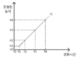
도 2 내지 도 4는 경화시간에 따른 조형판의 높이를 나타낸 그래프이다.1 is a conceptual view showing a photo-curing type 3D forming apparatus according to the present invention,
FIGS. 2 to 4 are graphs showing the height of the molding plate according to the curing time.
도 1은 본 발명에 따른 광경화식 3D 성형장치를 나타낸 개념도이다. 도 1에서 볼 수 있는 바와 같이, 본 3D 성형장치는 투명한 바닥판(210)을 가지고 광경화성 액체수지를 수용하는 수지조(200)를 갖는다. 수지조(200)는 프레임(100)에 의해 지지된다. 프레임(100)은 수지조(200)의 바닥판(210)을 테두리 영역에서 지지한다.BRIEF DESCRIPTION OF THE DRAWINGS FIG. 1 is a conceptual view showing a photo-curing type 3D forming apparatus according to the present invention. FIG. As can be seen in FIG. 1, the present 3D forming apparatus has a
광경화성 액체수지는 중합개시제와 중합금지제를 포함한다. 광경화성 액체수지에 빛이 조사되면, 중합개시제가 분해되어 라디칼을 발생한다. 중합개시제에 의해 발생된 라디칼은 초기에는 용존산소와 중합금지제와 반응한다. 라디칼에 의해 용존산소와 중합금지제가 소비되면, 라디칼이 광경화성 액체수지와 반응하여 중합이 이루어지면서 액체수지가 경화된다. 중합개시제와 중합금지제의 첨가량은 성형방법에 따라 차등을 둘 수 있다. 여기서, 라디칼이 광경화성 액체수지와 반응하여 중합이 일어나기 전까지를 반응유도기라고 한다. 액체수지에는 이형제가 첨가될 수도 있다.The photo-curable liquid resin includes a polymerization initiator and a polymerization inhibitor. When the photo-curable liquid resin is irradiated with light, the polymerization initiator is decomposed to generate radicals. The radicals generated by the polymerization initiator initially react with dissolved oxygen and a polymerization inhibitor. When the dissolved oxygen and the polymerization inhibitor are consumed by the radical, the radical reacts with the photo-curable liquid resin and the liquid resin is cured by polymerization. The addition amount of the polymerization initiator and the polymerization inhibitor may be varied depending on the molding method. Here, the radical initiator is referred to as a reaction initiator until the radical reacts with the photo-curable liquid resin to cause polymerization. A mold release agent may be added to the liquid resin.
수지조(200)의 하부에는 바닥판(210)을 향하여 이미지 광을 조사하는 이미지광 조사부(300)가 배치된다. 이미지광 조사부(300)는 광경화성 액체수지를 경화시키는데 필요한 빛을 발한다. 이미지광 조사부(300)는 LCD, LED, DMD 등 빛을 발하는 모든 디스플레이 장치로써 구비될 수 있다. 이미지조사부(300)는 제어부에 의해 단위성형층에 해당하는 층 이미지를 바닥판(210)을 향해 조사한다.An image
프레임(100)에는 수지조(200) 내부 영역에서 수직방향을 따라 승강 가능한 조형판(440)을 갖는 승강유니트(400)가 마련된다. 조형판(440)은 바닥판(210)과 평행한 하부면을 갖는다. 승강유니트(400)는 조형판(440)을 승강 구동하는 승강구동부(410)를 갖는다. 승강구동부(410)는 높이방향을 따라 승강 가능한 승강아암(420)을 포함한다. 승강아암(420)에는 조형판(440)과 매개부(430)가 결합된다. 매개부(430)는 조형판(440)이 바닥판(210)과 평행을 이룰 수 있도록 조정하며, 승강 이동시 떨림을 방지하는 역할을 한다. 한편, 승강유니트(400)는 수지조(200)와 결합되어, 수지조(200)가 조형판(440)에 대해 승강 가능하도록 변형할 수 있다.The
수지조(200)에는 광경화성 액체수지의 온도를 상승시키기 위한 전열부(350)가 설치된다. 전열부(350)는 이미지광 조사부와 수지조에 각각 접촉되어, 이미지광 조사부(300) 또는 별도의 가열장치에서 발생하는 열을 수지조(200)로 전달한다. 이에 따라, 수지조(200)에 수용된 액체수지(P)의 온도가 상승하여 점성이 낮아진다. 액체수지(P)의 점성이 낮아지면, 액체수지(P)의 조형판(440)과 바닥판(210) 사이 공간으로의 침투가 용이해진다. 수지조(200)에는 별도의 가열장치가 추가로 설치될 수 있다.In the
한편, 본 3D 성형장치는 수지조(200) 내부에 열경화성 액체수지(P)를 공급하는 공급부를 포함한다. 그리고 제어부는 승강구동부(410)와 공급부가 상호 연동되도록 제어할 수 있다.The 3D molding apparatus includes a supply unit for supplying the thermosetting liquid resin (P) into the resin tank (200). The control unit may control the
본 3D 성형장치는 수지조(200) 내부에서 승강 가능하게 설치되어, 열경화성 액체수지(P)가 하방을 향해 유동하도록 유도하는 유동 안내부를 더 포함할 수 있다.The 3D forming apparatus may further include a flow guide portion that is installed in the
이러한 구조를 갖는 광경화식 3D 성형장치에 의해, 다음과 같은 순서에 따라 3D 조형물이 성형된다.With the photo-curing type 3D molding apparatus having such a structure, the 3D molding is formed according to the following procedure.
먼저, 제어부는 열경화성 액체수지(P) 공급부를 통해 수지조(200) 내에 광경화성 액체수지(P)를 투입한다. 사용자가 임의로 액체수지(P)를 투입할 수도 있다. 이때, 광경화성 액체수지(P)는 수지조(200) 내부에서 적어도 하나의 단위성형층의 두께만큼 형성될 정도로 투입된다. 그리고 제어부는 조형판(440)을 바닥판(210)과의 사이 간격이 적어도 단일의 단위성형층의 일부 두께만큼 이격되도록 액체수지(P) 내에 침지한다.First, the control unit injects the photo-curable liquid resin (P) into the resin tank (200) through the thermosetting liquid resin (P) supply unit. The liquid resin P may be supplied by the user. At this time, the photo-curable liquid resin P is injected into the
다음으로, 제어부는 이미지광 조사부(300)를 통해 바닥판(210)을 향하여 단일의 제1 층이미지광을 조사한다. 단일의 제1 층이미지광이 조사되면, 광경화성 액체수지(P)는 반응유도기를 거쳐 경화된다. 이때, 제어부는 단일의 제1 단위성형층이 완전히 경화되기 전에 단위성형층의 적어도 일부 두께 범위 내에서 조형판(440)을 바닥판(210)에 대해 점진적으로 상승시킨다.Next, the control unit irradiates the single first layer image light toward the
도 2는 시간에 따른 조형판(440)의 높이를 나타낸 그래프이다. 도 2에서 볼 수 있는 바와 같이, 처음에는 조형판(440)이 바닥판(210)에 대해 제1성형층(10a)의 적어도 일부 두께 범위만큼의 간격(H0 부터 H1)을 두고 배치된다. 이 상태에서 제어부는 이미지광 조사부(300)를 통해 제1 층이미지광을 바닥판(210)을 향해 조사시키며, 액체수지(P)가 부분 경화되었을 때(T1) 조형판(440)을 점진적으로 상승시킨다. 제1 단위성형층이 부분 경화된 상태에서 상승되면, 제1단위성형층과 바닥판(210) 사이의 미세한 간격 사이로 액체수지가 모세관 현상에 따라 유입된다.2 is a graph showing the height of the
제어부는 조형판(440)을 점진적으로 계속해서 상승시킨다. 제어부는 조형판(440)을 계속해서 상승시키는 중에, 조형판(440)과 바닥판(210)) 사이 간격이 제1 성형층(10a)만큼 이격되었을 때(T2), 이미지광 조사부(300)에서 제2 층이미지광이 조사되도록 제어한다. 즉, 제1성형층(10a)의 두께는 H0 부터 H2까지의 거리가 된다. 제2성형층(10b)는 제1성형층(10a)의 하부면에서부터 형성되기 시작한다.The control unit continuously raises the
이러한 방식으로, 제어부는 조형판(440)을 멈추지 않고 연속적으로 상승시키면서 제1성형층(10a) 및 제2성형층(10b) 등 다수의 성형층을 적층할 수 있다. 빛이 계속해서 조사되므로, 제1성형층(10a) 및 제2성형층(10b)은 상부 측일수록 더 경화된 상태를 이루며, 바닥판(210)과 가까울수록 미경화상태가 된다.In this manner, the control section can stack a plurality of shaping layers such as the
제어부는 필요에 따라 조형판(440)의 상승 속도를 가변할 수 있다. 예를 들면, 하나의 단위성형층을 경화시킬 때마다 초기에는 저속으로 조형판(440)을 상승시키고 후기에는 비교적 고속으로 상승시킬 수 있다. 이와 같이, 연속적으로 조형판(440)을 상승시킬 경우, 제어부는 이미지광 조사부(300)가 조사하는 층이미지광을 연속적으로 변경하면서 조사한다.The control unit can vary the rising speed of the
도 3은 시간에 따른 조형판(440)의 높이 그래프의 다른 실시예이다. 도 3에서 볼 수 있는 바와 같이, 조형판(440)을 복수의 단계로 단속적으로 상승시킬 수 있다.3 is another embodiment of the height graph of the
처음에는 조형판(440)을 바닥판(210)에 대해 제1성형층의 적어도 일부 두께 범위만큼의 간격(H0 부터 H1)을 두고 배치한 상태에서 일정 시간동안 제1 층이미지광을 조사하여 제1성형층을 부분 경화시킨다. 그리고 제어부는 제1성형층이 부분 경화된 상태(T1)에서 조형판(440)을 점진적으로 상승시킨다. 제어부는 조형판(440)을 점진적으로 상승시키는 와중에 적절한 시점(T2)에서 이미지광 조사부(300)를 끄고 계속해서 조형판(440)을 점진적으로 소정 높이(H3)만큼 상승시킨다. 여기서, 제1 층이미지광을 끈 상태에서 조형판(440)을 상승시키는 높이(H2 부터 H3)는 제1성형층의 하부면과 바닥판 사이 간격이 제2성형층의 적어도 일부 두께 범위 만큼이다. 제1성형층은 제1 층이미지광이 조사된 시간(T0 부터 T2)동안 형성되는 높이(H0 부터 H2)만큼의 두께로 형성된다.The
그리고 제1성형층의 하부면과 바닥판(210) 사이 간격이 제2성형층의 적어도 일부 두께 범위만큼 간격(H3-H2)을 두고 배치된 상태에서 다시 일정시간 동안 제2 층이미지광을 조사하여 제2성형층을 부분 경화시킨다. 그리고 제2성형층이 부분 경화된 상태에서 조형판(440)을 점진적으로 상승시킨다. 조형판(440)을 점진적으로 상승시키는 와중에 적절한 시점(T4)에서 제2 층이미지광을 끄고 계속해서 조형판을 점진적으로 소정 높이(H5)만큼 상승시킨다. 여기서, 제2 층이미지광을 끈 상태에서 조형판(440)을 상승시키는 높이(H5-H4)는 제2성형층의 하부면과 바닥판(210) 사이 간격이 제3성형층의 적어도 일부 두께 범위 만큼이다.Then, the second layer image light is irradiated again for a certain period of time in a state in which the distance between the lower surface of the first shaping layer and the
제2성형층은 제2 층이미지광이 조사된 시간(T3 부터 T4)동안 형성되는 높이(H2 부터 H4)만큼의 두께로 형성된다.The second shaping layer is formed to a thickness equal to the height (H2 to H4) formed during the time (T3 to T4) at which the second layer image light is irradiated.
제2성형층의 하부면과 바닥판(210) 사이 간격이 제3성형층의 적어도 일부 두께 범위만큼 간격(H5-H4)을 두고 배치된 상태에서 다시 일정시간동안 제3 층이미지광을 조사하여 제3성형층을 부분 경화시킨다. 이하, 순차적으로 적층되는 후속 성형층의 적층과정은 상술한 제1성형층과 제2성형층의 적층과정과 동일하다.The third layer image light is again irradiated for a certain period of time in a state in which the distance between the lower surface of the second shaping layer and the
한편, T2 부터 T3, T4 부터 T5, T6 부터 T7과 같이 빛이 조사되지 않는 인터벌 없이 지속적으로 빛을 조사하면서 단속적으로 상승할 수도 있다. 이 경우, 조형판(440)이 정지상태일 때 바닥판(210)과 인접한 성형층이 완전 경화되지 않도록 한다.On the other hand, it may intermittently rise while continuously irradiating the light without intervals such as T2 to T3, T4 to T5, and T6 to T7. In this case, when the
이러한 도 3에서와 같은 적층방식에 따라, 본 광경화식 3D 성형방법은 조형판(440)을 소정 높이 상승시킨 후 다시 하강하는 불필요한 동작 없이, 상승 및 정지 동작만으로 3D 조형물을 성형할 수 있다.According to the lamination method as shown in FIG. 3, the 3D stereolithography method of the present invention can mold a 3D sculpture only by lifting and stopping operation without unnecessary operation of raising the
또한, 다른 실시예로서 도 4에서와 같이 하나의 단위성형층을 위한 층이미지광을 조사하는 동안 조형판(440)을 복수의 단계로 단속적으로 상승시킬 수도 있다. 이 경우, 단위성형층은 도 3에서보다 안정적으로 형성될 수 있다.Further, as another embodiment, the
Claims (6)
단위성형층을 위한 층이미지광을 조사하는 동안 상기 단위성형층의 적어도 일부의 두께 범위 내에서 상기 조형판을 상기 수지조 바닥판에 대해 상대적으로 상승시키며 조형하는 것을 특징으로 하는 광경화식 3D 성형방법.A photocurable 3D forming method for forming a molding by layering a photocurable liquid resin contained in a resin tank having a transparent bottom plate on a molding plate,
Characterized in that the shaping plate is raised and shaped relative to the resin trough plate within a thickness range of at least a part of the unit shaping layer while irradiating the layer image light for the unit shaping layer .
상기 조형판의 상대적 상승은 연속적으로 이루어지는 것을 특징으로 하는 광경화식 3D 성형방법.The method according to claim 1,
Wherein the relative rise of the shaping plate is continuously performed.
상기 조형판의 상대적 상승은 복수 단계로 단속적으로 이루어지는 것을 특징으로 하는 광경화식 3D 성형방법.The method according to claim 1,
Wherein the relative elevation of the shaping plate is intermittently performed in a plurality of steps.
상기 단위성형층의 조형 중에 상기 액체수지에 대해 가열하는 것을 특징으로 하는 광경화식 3D 성형방법.The method according to claim 1,
And heating the liquid resin during molding of the unit molding layer.
투명한 바닥판을 가지고 광경화성 액체수지를 수용하는 수지조와;
상기 바닥판과 평행한 하부면을 가지고 상기 수지조 내에서 승강 가능한 조형판과;
상기 수지조와 상기 조형판 중 적어도 하나를 승강 구동하는 승강구동부와;
상기 수지조의 하부에서 상기 바닥판을 향하여 층이미지광을 조사하는 이미지광 조사부와;
단일의 단위성형층을 위한 상기 층이미지광을 조사하는 동안 상기 단위성형층의 적어도 일부의 두께 범위 내에서 상기 조형판을 상기 수지조의 상기 바닥판에 대해 상대적으로 상승시키도록 상기 승강구동부를 제어하는 제어부를 포함하는 것을 특징으로 하는 광경화식 3D 성형장치.A light-curing 3D forming apparatus for forming a molding by laminating a plurality of unit forming layers,
A resin vessel for receiving the photo-curable liquid resin with a transparent bottom plate;
A shaping plate having a lower surface parallel to the bottom plate and capable of ascending and descending in the resin tank;
An elevation driving unit for elevating and lowering at least one of the resin tank and the shaping plate;
An image light irradiating unit for irradiating the layer image light from the bottom of the resin tank toward the bottom plate;
Controlling the elevation driving section to raise the shaping plate relative to the bottom plate of the resin tank within a thickness range of at least a part of the unit shaping layer while irradiating the layer image light for a single unit shaping layer And a control unit.
상기 광경화성 액체수지의 온도를 상승시키는 가열부를 더 포함하는 것을 특징으로 하는 광경화식 3D 성형장치.6. The method of claim 5,
Further comprising a heating unit for raising the temperature of the photo-curable liquid resin.
Applications Claiming Priority (3)
| Application Number | Priority Date | Filing Date | Title |
|---|---|---|---|
| KR20140024109 | 2014-02-28 | ||
| KR1020140024109 | 2014-02-28 | ||
| PCT/KR2015/001958 WO2015130139A1 (en) | 2014-02-28 | 2015-02-27 | Photo-curable 3d forming method and photo-curable 3d forming apparatus |
Related Child Applications (2)
| Application Number | Title | Priority Date | Filing Date |
|---|---|---|---|
| KR1020187014662A Division KR101887419B1 (en) | 2014-02-28 | 2015-02-27 | Photo-curable 3d forming method and photo-curable 3d forming apparatus |
| KR1020187014663A Division KR101887420B1 (en) | 2014-02-28 | 2015-02-27 | Photo-curable 3d forming method and photo-curable 3d forming apparatus |
Publications (2)
| Publication Number | Publication Date |
|---|---|
| KR20160110431A KR20160110431A (en) | 2016-09-21 |
| KR101863826B1 true KR101863826B1 (en) | 2018-06-01 |
Family
ID=54009382
Family Applications (3)
| Application Number | Title | Priority Date | Filing Date |
|---|---|---|---|
| KR1020167021887A Active KR101863826B1 (en) | 2014-02-28 | 2015-02-27 | Photo-curable 3d forming method and photo-curable 3d forming apparatus |
| KR1020187014663A Active KR101887420B1 (en) | 2014-02-28 | 2015-02-27 | Photo-curable 3d forming method and photo-curable 3d forming apparatus |
| KR1020187014662A Active KR101887419B1 (en) | 2014-02-28 | 2015-02-27 | Photo-curable 3d forming method and photo-curable 3d forming apparatus |
Family Applications After (2)
| Application Number | Title | Priority Date | Filing Date |
|---|---|---|---|
| KR1020187014663A Active KR101887420B1 (en) | 2014-02-28 | 2015-02-27 | Photo-curable 3d forming method and photo-curable 3d forming apparatus |
| KR1020187014662A Active KR101887419B1 (en) | 2014-02-28 | 2015-02-27 | Photo-curable 3d forming method and photo-curable 3d forming apparatus |
Country Status (3)
| Country | Link |
|---|---|
| US (1) | US11318668B2 (en) |
| KR (3) | KR101863826B1 (en) |
| WO (1) | WO2015130139A1 (en) |
Families Citing this family (3)
| Publication number | Priority date | Publication date | Assignee | Title |
|---|---|---|---|---|
| CN107031036B (en) * | 2017-06-06 | 2022-03-11 | 清锋(北京)科技有限公司 | Three-dimensional printing device and three-dimensional printing method |
| CN109228316B (en) * | 2018-10-22 | 2021-09-07 | 泰州极光电子科技有限公司 | Quick 3D printing system |
| KR102148822B1 (en) | 2020-04-21 | 2020-08-27 | (주)아름덴티스트리 | 3D printer |
Citations (1)
| Publication number | Priority date | Publication date | Assignee | Title |
|---|---|---|---|---|
| US20130249146A1 (en) * | 2011-01-18 | 2013-09-26 | Dws S.R.L. | Method for producing a three-dimensional object and stereolithography machine employing said method |
Family Cites Families (5)
| Publication number | Priority date | Publication date | Assignee | Title |
|---|---|---|---|---|
| JP3664200B2 (en) * | 1996-12-03 | 2005-06-22 | ナブテスコ株式会社 | Stereolithography method |
| JPH10249943A (en) * | 1997-03-10 | 1998-09-22 | Hitachi Ltd | Stereolithography |
| WO2008055533A1 (en) * | 2006-11-10 | 2008-05-15 | Envisiontec Gmbh | Continuous, generative method and apparatus for the production of a three-dimensional object |
| IT1400015B1 (en) * | 2010-05-17 | 2013-05-09 | Dws Srl | PERFECT STEREOLITOGRAPHIC MACHINE |
| WO2014126834A2 (en) * | 2013-02-12 | 2014-08-21 | Eipi Systems, Inc. | Method and apparatus for three-dimensional fabrication with feed through carrier |
-
2015
- 2015-02-27 KR KR1020167021887A patent/KR101863826B1/en active Active
- 2015-02-27 KR KR1020187014663A patent/KR101887420B1/en active Active
- 2015-02-27 US US15/121,191 patent/US11318668B2/en active Active
- 2015-02-27 KR KR1020187014662A patent/KR101887419B1/en active Active
- 2015-02-27 WO PCT/KR2015/001958 patent/WO2015130139A1/en not_active Ceased
Patent Citations (1)
| Publication number | Priority date | Publication date | Assignee | Title |
|---|---|---|---|---|
| US20130249146A1 (en) * | 2011-01-18 | 2013-09-26 | Dws S.R.L. | Method for producing a three-dimensional object and stereolithography machine employing said method |
Also Published As
| Publication number | Publication date |
|---|---|
| WO2015130139A1 (en) | 2015-09-03 |
| KR20180059949A (en) | 2018-06-05 |
| KR101887420B1 (en) | 2018-08-13 |
| US11318668B2 (en) | 2022-05-03 |
| US20160368206A1 (en) | 2016-12-22 |
| KR20160110431A (en) | 2016-09-21 |
| KR20180059950A (en) | 2018-06-05 |
| KR101887419B1 (en) | 2018-08-13 |
Similar Documents
| Publication | Publication Date | Title |
|---|---|---|
| CA2657678C (en) | Method and system for layerwise production of a tangible object | |
| WO2016172784A1 (en) | Improved stereolithography system | |
| JP2017503678A (en) | Device for processing photopolymerizable materials to build shaped bodies layer by layer | |
| KR101863826B1 (en) | Photo-curable 3d forming method and photo-curable 3d forming apparatus | |
| KR20190064950A (en) | A 3D printer which forms a 3-dimensional object | |
| JP2015027738A (en) | 3D modeling equipment | |
| WO2012150497A1 (en) | Perfected method for manufacturing three-dimensional objects in layers and perfected stereolithography machine using said method | |
| JP2014221538A (en) | Formation method and formation apparatus | |
| KR101982112B1 (en) | Bottom-up type 3D printer | |
| KR20160144838A (en) | Apparatus for stereolithography of layer form | |
| KR101977327B1 (en) | supporting unit for printing mold and 3D printer and printing method using the same | |
| KR101842511B1 (en) | 3d printer | |
| KR20190115528A (en) | Driving and controlling method for 3D printer of DLP type | |
| JP4040177B2 (en) | 3D modeling apparatus, 3D modeling method, and medium on which 3D modeling control program is recorded | |
| KR20150108532A (en) | 3d printer and device to illuminates image exposed directly | |
| KR20190050732A (en) | Vat for 3D Printer Capable of Fast Curing | |
| KR101874791B1 (en) | Method for photo-curable 3D laminated molding and apparatus for photo-curable 3D laminated molding | |
| JP2021062583A5 (en) | ||
| KR101118764B1 (en) | Apparatus for manufacturing array lens and method for manufacturing the array lens using the same | |
| CN111660402B (en) | Additive manufacturing system and container | |
| JPH07205304A (en) | Optical shaping apparatus | |
| KR20170052037A (en) | Stereolithography apparatus and manufacturing method thereof | |
| TWI607860B (en) | A method of reducing the pulling force of the forming process of a bottom-up vat photopolymerization device | |
| JP2023073097A (en) | Optical shaping device and method for manufacturing shaped article | |
| JP2023073096A (en) | Optical shaping device and method for manufacturing shaped article |
Legal Events
| Date | Code | Title | Description |
|---|---|---|---|
| A201 | Request for examination | ||
| PA0105 | International application |
Patent event date: 20160810 Patent event code: PA01051R01D Comment text: International Patent Application |
|
| PA0201 | Request for examination | ||
| PG1501 | Laying open of application | ||
| E902 | Notification of reason for refusal | ||
| PE0902 | Notice of grounds for rejection |
Comment text: Notification of reason for refusal Patent event date: 20170803 Patent event code: PE09021S01D |
|
| E701 | Decision to grant or registration of patent right | ||
| PE0701 | Decision of registration |
Patent event code: PE07011S01D Comment text: Decision to Grant Registration Patent event date: 20180223 |
|
| A107 | Divisional application of patent | ||
| PA0104 | Divisional application for international application |
Comment text: Divisional Application for International Patent Patent event code: PA01041R01D Patent event date: 20180524 |
|
| GRNT | Written decision to grant | ||
| PR0701 | Registration of establishment |
Comment text: Registration of Establishment Patent event date: 20180528 Patent event code: PR07011E01D |
|
| PR1002 | Payment of registration fee |
Payment date: 20180529 End annual number: 3 Start annual number: 1 |
|
| PG1601 | Publication of registration | ||
| PR1001 | Payment of annual fee |
Payment date: 20210615 Start annual number: 4 End annual number: 4 |
|
| PR1001 | Payment of annual fee |
Payment date: 20220517 Start annual number: 5 End annual number: 5 |
|
| PR1001 | Payment of annual fee |
Payment date: 20230816 Start annual number: 6 End annual number: 6 |
|
| PR1001 | Payment of annual fee |
Payment date: 20240627 Start annual number: 7 End annual number: 7 |
|
| PR1001 | Payment of annual fee |
Payment date: 20250630 Start annual number: 8 End annual number: 8 |