KR101826140B1 - Method for operating memory controller, and memory system having the same - Google Patents
Method for operating memory controller, and memory system having the same Download PDFInfo
- Publication number
- KR101826140B1 KR101826140B1 KR1020110077748A KR20110077748A KR101826140B1 KR 101826140 B1 KR101826140 B1 KR 101826140B1 KR 1020110077748 A KR1020110077748 A KR 1020110077748A KR 20110077748 A KR20110077748 A KR 20110077748A KR 101826140 B1 KR101826140 B1 KR 101826140B1
- Authority
- KR
- South Korea
- Prior art keywords
- memory
- read
- rtc
- value
- time
- Prior art date
- Legal status (The legal status is an assumption and is not a legal conclusion. Google has not performed a legal analysis and makes no representation as to the accuracy of the status listed.)
- Active
Links
Images


Classifications
-
- G—PHYSICS
- G06—COMPUTING OR CALCULATING; COUNTING
- G06F—ELECTRIC DIGITAL DATA PROCESSING
- G06F13/00—Interconnection of, or transfer of information or other signals between, memories, input/output devices or central processing units
- G06F13/14—Handling requests for interconnection or transfer
- G06F13/16—Handling requests for interconnection or transfer for access to memory bus
-
- G—PHYSICS
- G06—COMPUTING OR CALCULATING; COUNTING
- G06F—ELECTRIC DIGITAL DATA PROCESSING
- G06F11/00—Error detection; Error correction; Monitoring
-
- G—PHYSICS
- G06—COMPUTING OR CALCULATING; COUNTING
- G06F—ELECTRIC DIGITAL DATA PROCESSING
- G06F11/00—Error detection; Error correction; Monitoring
- G06F11/07—Responding to the occurrence of a fault, e.g. fault tolerance
- G06F11/08—Error detection or correction by redundancy in data representation, e.g. by using checking codes
- G06F11/10—Adding special bits or symbols to the coded information, e.g. parity check, casting out 9's or 11's
- G06F11/1008—Adding special bits or symbols to the coded information, e.g. parity check, casting out 9's or 11's in individual solid state devices
- G06F11/1048—Adding special bits or symbols to the coded information, e.g. parity check, casting out 9's or 11's in individual solid state devices using arrangements adapted for a specific error detection or correction feature
-
- G—PHYSICS
- G06—COMPUTING OR CALCULATING; COUNTING
- G06F—ELECTRIC DIGITAL DATA PROCESSING
- G06F12/00—Accessing, addressing or allocating within memory systems or architectures
-
- G—PHYSICS
- G11—INFORMATION STORAGE
- G11C—STATIC STORES
- G11C16/00—Erasable programmable read-only memories
- G11C16/02—Erasable programmable read-only memories electrically programmable
- G11C16/06—Auxiliary circuits, e.g. for writing into memory
-
- G—PHYSICS
- G11—INFORMATION STORAGE
- G11C—STATIC STORES
- G11C16/00—Erasable programmable read-only memories
- G11C16/02—Erasable programmable read-only memories electrically programmable
- G11C16/06—Auxiliary circuits, e.g. for writing into memory
- G11C16/32—Timing circuits
-
- G—PHYSICS
- G06—COMPUTING OR CALCULATING; COUNTING
- G06F—ELECTRIC DIGITAL DATA PROCESSING
- G06F11/00—Error detection; Error correction; Monitoring
- G06F11/07—Responding to the occurrence of a fault, e.g. fault tolerance
- G06F11/08—Error detection or correction by redundancy in data representation, e.g. by using checking codes
- G06F11/10—Adding special bits or symbols to the coded information, e.g. parity check, casting out 9's or 11's
- G06F11/1076—Parity data used in redundant arrays of independent storages, e.g. in RAID systems
-
- G—PHYSICS
- G11—INFORMATION STORAGE
- G11C—STATIC STORES
- G11C16/00—Erasable programmable read-only memories
- G11C16/02—Erasable programmable read-only memories electrically programmable
- G11C16/06—Auxiliary circuits, e.g. for writing into memory
- G11C16/26—Sensing or reading circuits; Data output circuits
-
- G—PHYSICS
- G11—INFORMATION STORAGE
- G11C—STATIC STORES
- G11C16/00—Erasable programmable read-only memories
- G11C16/02—Erasable programmable read-only memories electrically programmable
- G11C16/06—Auxiliary circuits, e.g. for writing into memory
- G11C16/34—Determination of programming status, e.g. threshold voltage, overprogramming or underprogramming, retention
- G11C16/349—Arrangements for evaluating degradation, retention or wearout, e.g. by counting erase cycles
Landscapes
- Engineering & Computer Science (AREA)
- Theoretical Computer Science (AREA)
- Physics & Mathematics (AREA)
- General Engineering & Computer Science (AREA)
- General Physics & Mathematics (AREA)
- Quality & Reliability (AREA)
- Techniques For Improving Reliability Of Storages (AREA)
- Read Only Memory (AREA)
Abstract
리드 리트라이 동작의 최대 회수를 제어할 수 있는 메모리 컨트롤러의 동작 방법이 개시된다. 상기 방법은 불휘발성 메모리의 저장 영역에 데이터를 프로그램하는 프로그램 동작이 수행될 때 상기 프로그램 동작이 수행된 시각을 지시하는 제1실시간 클락 값을 상기 불휘발성 메모리에 프로그램하는 단계와, 상기 저장 영역에 프로그램된 상기 데이터에 대한 리드 동작이 수행될 때 상기 불휘발성 메모리로부터 읽혀진 상기 제1실시간 클락 값과 상기 리드 동작이 수행된 시각을 지시하는 제2실시간 클락 값을 이용하여 상기 저장 영역에 대한 정보를 획득하는 단계와, 상기 저장 영역에 대한 리드 리트라이 동작이 수행될 때 상기 정보를 이용하여 상기 리드 리트라이 동작의 최대 회수를 감소시키는 단계를 포함한다.A method of operating a memory controller capable of controlling the maximum number of read retry operations is disclosed. The method includes programming a first real-time clock value in the nonvolatile memory to indicate a time at which the program operation was performed when a program operation for programming data into a storage area of the nonvolatile memory is performed, Volatile memory and a second real-time clock value indicating a time at which the read operation is performed when the read operation is performed on the programmed data, And reducing the maximum number of the read retry operations using the information when the read retry operation for the storage area is performed.
Description
본 발명의 개념에 따른 실시 예는 메모리 컨트롤러의 동작 방법에 관한 것으로서, 특히 동일한 저장 영역에 대한 프로그램 동작 시각과 리드 동작 시각의 차이를 실시간 클락(real time clock) 회로를 이용하여 계산하고 계산 결과에 따라 상기 저장 영역에 대한 리드 리트라이 동작의 최대 회수를 감소시킬 수 있는 메모리 컨트롤러의 동작 방법과 상기 방법을 수행할 수 있는 메모리 시스템에 관한 것이다.The embodiment of the present invention relates to a method of operating a memory controller. In particular, a difference between a program operation time and a read operation time for the same storage area is calculated using a real time clock circuit, And to reduce the maximum number of read retry operations for the storage area, and a memory system capable of performing the method.
메모리(memory)는 상기 메모리로 전원이 공급되는 동안에만 상기 메모리에 저장된 데이터를 유지하는 휘발성(volatile) 메모리와 상기 메모리로 전원의 공급이 차단되더라도 상기 메모리에 저장된 데이터를 유지하는 불휘발성(non-volatile) 메모리로 분류된다.A memory is a volatile memory that retains data stored in the memory only while power is supplied to the memory and a nonvolatile memory that retains data stored in the memory even when power is supplied to the memory. volatile memory.
상기 휘발성 메모리는 DRAM(dynamic random access memory)를 포함하고, 상기 불휘발성 메모리는 ROM(read only memory), 플래시(flash) 메모리, 및 저항성 (resistive) 메모리를 포함한다. 상기 플래시 메모리는 NAND 플래시 메모리와 NOR 플래시 메모리를 포함하다.The volatile memory includes a dynamic random access memory (DRAM), and the nonvolatile memory includes a read only memory (ROM), a flash memory, and a resistive memory. The flash memory includes a NAND flash memory and a NOR flash memory.
NAND 플래시 메모리의 제조 공정이 미세화됨에 따라, 상기 NAND 플래시 메모리의 수명이 짧아지고 상기 NAND 플래시 메모리에 저장된 데이터를 리드하는 리드 (read) 동작에서 리드 에러(read error)는 점점 증가한다.As the fabrication process of the NAND flash memory becomes finer, the life of the NAND flash memory is shortened and a read error is gradually increased in a read operation of reading data stored in the NAND flash memory.
상기 리드 동작 동안에 발생한 상기 리드 에러를 복구하기 위해, 상기 NAND 플래시 메모리는 정해진 회수 범위 이내에서 리드 데이터에 대한 상기 리드 동작이 성공할 때까지 리드 전압 레벨을 변동시켜가면서 상기 리드 데이터에 대한 상기 리드 에러를 복구하는 리드 리트라이 동작(read retry operation)을 수행한다.The NAND flash memory may change the read voltage level for the read data while varying the read voltage level until the read operation for the read data is successful within a predetermined number of times to recover the read error generated during the read operation And performs a read retry operation to recover the data.
리드 에러를 복구하기 위한 리드 리트라이 동작이 빈번히 수행됨에 따라, NAND 플래시 메모리의 성능과 상기 NAND 플래시 메모리를 포함하는 메모리 시스템의 성능이 저하된다.As the read retry operation for recovering the read error is frequently performed, the performance of the NAND flash memory and the performance of the memory system including the NAND flash memory are degraded.
따라서 리드 동작 동안 NAND 플래시 메모리의 성능과 상기 NAND 플래시 메모리를 포함하는 메모리 시스템의 성능을 개선하기 위한 방법이 필요하다.Therefore, there is a need for a method for improving the performance of the NAND flash memory and the performance of the memory system including the NAND flash memory during the read operation.
본 발명이 이루고자 하는 기술적인 과제는 리드 동작 동안에 NAND 플래시 메모리의 성능과 상기 NAND 플래시 메모리를 포함하는 메모리 시스템의 성능을 개선하기 위한 방법과 상기 방법을 수행할 수 있는 전자 장치를 제공하는 것이다.SUMMARY OF THE INVENTION It is an object of the present invention to provide a method for improving the performance of a NAND flash memory and a memory system including the NAND flash memory during a read operation and an electronic device capable of performing the method.
본 발명의 실시 예에 따른 메모리 컨트롤러의 동작 방법은 불휘발성 메모리의 저장 영역에 데이터를 프로그램하는 프로그램 동작이 수행될 때 상기 프로그램 동작이 수행된 시각(time-of-day)을 지시하는 제1실시간 클락(real time clock(RTC)) 값을 상기 불휘발성 메모리에 프로그램하는 단계와, 상기 저장 영역에 프로그램된 상기 데이터에 대한 리드 동작이 수행될 때 상기 불휘발성 메모리로부터 읽혀진 상기 제1TRC 값과 상기 리드 동작이 수행된 시각을 지시하는 제2RTC 값을 이용하여 상기 저장 영역에 대한 정보를 획득하는 단계와, 상기 저장 영역에 대한 리드 리트라이 동작이 수행될 때 상기 정보를 이용하여 상기 리드 리트라이 동작의 최대 회수를 제어하는 단계를 포함한다.A method of operating a memory controller according to an embodiment of the present invention is a method for operating a memory controller in a nonvolatile memory, the method comprising: when a program operation for programming data into a storage area of a nonvolatile memory is performed, Programmed into the nonvolatile memory, the value of the real time clock (RTC) to be written to the nonvolatile memory when the read operation is performed on the data programmed into the storage area, Acquiring information on the storage area using a second RTC value indicating a time at which the operation is performed; and performing a read retry operation using the information when performing a read retry operation on the storage area, And controlling the maximum number of times.
상기 메모리 컨트롤러의 동작 방법은 상기 메모리 컨트롤러가 부팅(booting)될 때 호스트로부터 출력된 부팅 시각을 지시하는 부팅 RTC 값을 카운터를 이용하여 생성하는 단계와, 상기 부팅 RTC 값을 상기 카운터를 이용하여 상기 제1RTC 값과 상기 제2RTC 값 각각으로 업-데이트하는 단계를 더 포함한다.The method of operating the memory controller may include generating a boot RTC value indicating a boot time output from a host when the memory controller is booted by using a counter, And up-dateing the first RTC value and the second RTC value, respectively.
상기 정보를 획득하는 단계는 상기 제2RTC 값과 상기 제1RTC 값의 차이를 이용하여 상기 정보를 획득한다.The obtaining of the information may use the difference between the second RTC value and the first RTC value to obtain the information.
상기 메모리 컨트롤러의 동작 방법은 실시간 클락 회로를 이용하여 상기 제1RTC 값을 계산한 후 상기 제2RTC 값을 계산하는 단계를 더 포함한다. 상기 제1RTC 값과 상기 제2RTC 값 각각은 상기 메모리 컨트롤러가 부팅될 때 호스트로부터 출력된 부팅 시각을 나타내는 부팅 RTC 값으로부터 상기 실시간 클락 회로에 의하여 업-데이트된 값이다.The method of operating the memory controller may further include calculating the first RTC value using the real-time clock circuit and then calculating the second RTC value. Each of the first RTC value and the second RTC value is a value up-dated by the real time clock circuit from a boot RTC value indicating a boot time output from the host when the memory controller is booted.
상기 리드 리트라이 동작을 제어하는 단계는 상기 리드 리트라이 동작의 상기 최대 회수를 감소시킨다.The step of controlling the read retry operation reduces the maximum number of times of the read retry operation.
상기 리드 리트라이 동작을 제어하는 단계는 상기 리드 리트라이 동작에 필요한 초기 리드 전압 레벨을 제어하기 위한 제어 신호를 상기 불휘발성 메모리로 전송한다.The step of controlling the read retry operation transmits a control signal for controlling an initial read voltage level required for the read retry operation to the nonvolatile memory.
본 발명의 실시예에 따른 메모리 시스템은 저장 영역을 포함하는 불휘발성 메모리와, 상기 불휘발성 메모리의 동작을 제어하는 메모리 컨트롤러를 포함하며, 상기 메모리 컨트롤러는 상기 저장 영역에 대한 리드 동작 동안 상기 저장 영역에 대해 프로그램 동작이 수행된 제1시각과 상기 저장 영역에 대해 상기 리드 동작이 수행된 제2시각의 차이를 계산하고 계산 결과에 따라 상기 저장 영역에 대한 리드 리트라이 동작의 최대 회수를 제어한다.A memory system according to an embodiment of the present invention includes a nonvolatile memory including a storage area and a memory controller for controlling the operation of the nonvolatile memory, And a second time when the read operation is performed with respect to the storage area, and controls the maximum number of read retries for the storage area in accordance with the calculation result.
상기 메모리 컨트롤러는 클락 신호에 응답하여 제1실시간 클락(real time clock(RTC)) 값과 제2RTC 값을 생성하는 실시간 클락(RTC) 회로와, 상기 제1시각을 지시하는 상기 제1RTC 값을 상기 불휘발성 메모리로의 프로그램을 제어하고, 상기 리드 동작이 수행될 때 상기 불휘발성 메모리로부터 읽혀진 상기 제1RTC 값과 상기 제2시각을 지시하는 상기 제2RTC 값을 이용하여 상기 차이를 계산하고, 상기 리트라이 동작이 수행될 때 상기 차이를 이용하여 상기 리드 리트라이 동작의 상기 최대 회수의 감소를 제어하는 마이크로프로세서를 포함한다.Wherein the memory controller comprises: a real-time clock (RTC) circuit responsive to a clock signal for generating a first real-time clock (RTC) value and a second RTC value; Volatile memory and calculates the difference using the first RTC value read from the nonvolatile memory and the second RTC value indicating the second time when the read operation is performed, And a microprocessor for controlling the decrease of the maximum number of times of the read retry operation using the difference when the trie operation is performed.
상기 RTC 회로는 상기 클락 신호에 응답하여 상기 제1RTC 값과 상기 제2TRC 값을 생성하기 위한 카운터를 포함한다.The RTC circuit includes a counter for generating the first RTC value and the second TRC value in response to the clock signal.
상기 마이크로프로세서는 상기 리드 리트라이 동작에 필요한 초기 리드 전압 레벨을 제어하기 위한 제어 신호를 상기 불휘발성 메모리로 전송한다.The microprocessor transmits a control signal for controlling an initial read voltage level required for the read retry operation to the nonvolatile memory.
상기 메모리 시스템은 상기 불휘발성 메모리와 상기 메모리 컨트롤러를 포함하는 MCP(multi-chip package)이다.The memory system is a multi-chip package (MCP) including the nonvolatile memory and the memory controller.
실시 예에 따라 상기 메모리 시스템은 상기 프로그램 동작을 수행하기 위해 호스트로부터 출력된 프로그램 데이터를 상기 메모리 컨트롤러로 전송하고, 상기 리드 리트라이 동작에 따라 상기 메모리 컨트롤러로부터 출력된 리드 데이터를 상기 호스트로 전송하는 카드 인터페이스를 더 포함한다.According to an embodiment of the present invention, the memory system transmits program data output from a host to the memory controller to perform the program operation, and transmits read data output from the memory controller to the host in accordance with the read retry operation Card interface.
다른 실시 예에 따라 상기 메모리 시스템은 광학 이미지를 디지털 이미지로 변환하기 위한 이미지 센서를 더 포함하고, 상기 메모리 컨트롤러는 상기 디지털 이미지를 상기 저장 영역에 프로그램하는 상기 프로그램 동작 또는 상기 저장 영역에 저장된 상기 디지털 이미지를 리드하는 상기 리드 동작을 제어한다.According to another embodiment, the memory system further comprises an image sensor for converting an optical image into a digital image, wherein the memory controller is operable to perform the program operation for programming the digital image into the storage area, And controls the read operation to read the image.
또 다른 실시 예에 따라 상기 메모리 시스템은 무선 송수신기를 더 포함하며, 상기 마이크프로세서는 상기 무선 송수신기로부터 출력된 데이터를 상기 저장 영역에 프로그램하는 상기 프로그램 동작 또는 상기 리드 리트라이 동작에 따라 상기 저장 영역으로부터 리드된 데이터를 상기 무선 송수신기로의 전송을 제어한다.According to yet another embodiment, the memory system further comprises a wireless transceiver, wherein the microphone processor is operable to receive data from the storage area in accordance with the program operation or the read retry operation of programming data output from the wireless transceiver into the storage area And controls the transmission of the read data to the radio transceiver.
본 발명의 실시 예에 따른 메모리 컨트롤러의 동작 방법은 불휘발성 메모리의 동일한 저장 영역에 대해 프로그램 동작과 리드 동작이 시간 차이를 두고 수행될 때 상기 시간 차이를 실시간 클락 회로를 이용하여 계산하고 계산 결과에 따라 상기 저장 영역에 대한 리드 리트라이 동작의 최대 회수를 감소시킬 수 있는 효과가 있다.The operation method of the memory controller according to the embodiment of the present invention calculates the time difference using the real time clock circuit when the program operation and the read operation are performed with respect to the same storage area of the nonvolatile memory with a time difference, Accordingly, the maximum number of read retry operations for the storage area can be reduced.
따라서 상기 메모리 컨트롤러를 포함하는 메모리 시스템의 리드 성능은 향상된다.Therefore, the read performance of the memory system including the memory controller is improved.
또한, 본 발명의 실시 예에 따른 메모리 컨트롤러의 동작 방법은 상기 시간 차이를 상기 실시간 클락 회로를 이용하여 계산하고 계산 결과에 따라 상기 불휘발성 메모리의 수명을 연장하기 위한 웨어 레벨링을 효과적으로 수행할 수 있는 효과가 있다.The operation method of the memory controller according to the embodiment of the present invention can calculate the time difference using the real time clock circuit and effectively perform wear leveling for extending the service life of the nonvolatile memory according to the calculation result It is effective.
본 발명의 상세한 설명에서 인용되는 도면을 보다 충분히 이해하기 위하여 각 도면의 상세한 설명이 제공된다.
도 1은 본 발명의 실시예에 따른 메모리 컨트롤러를 포함하는 메모리 시스템의 블록도를 나타낸다.
도 2는 도 1에 도시된 메모리 컨트롤러의 블록도를 나타낸다.
도 3은 도 2에 도시된 실시간 클락(real time clock) 회로의 동작을 설명하기 위한 신호 파형도를 나타낸다.
도 4는 시간의 경과에 따른 전하 손실에 기인한 불휘발성 메모리 셀들의 문턱 전압의 산포를 나타낸다.
도 5는 프로그램 시각과 리드 시각의 차이에 따른 문턱 전압의 변화와 리드 리트라이의 최대 회수의 변화를 예시적으로 나타내는 표이다.
도 6은 도 1에 도시된 메모리 시스템의 동작을 설명하기 위한 신호 흐름도를 나타낸다.
도 7은 도 1에 도시된 메모리 시스템을 포함하는 전자 장치의 일 실시예를 나타낸다.
도 8은 도 1에 도시된 메모리 시스템을 포함하는 전자 장치의 다른 실시예를 나타낸다.
도 9는 도 1에 도시된 메모리 시스템을 포함하는 전자 장치의 또 다른 실시예를 나타낸다.
도 10은 도 1에 도시된 메모리 시스템을 포함하는 전자 장치의 또 다른 실시예를 나타낸다.
도 11은 도 1에 도시된 메모리 시스템을 포함하는 전자 장치의 또 다른 실시예를 나타낸다.
도 12는 도 1에 도시된 메모리 시스템을 포함하는 전자 장치의 또 다른 실시예를 나타낸다.
도 13은 도 12에 도시된 전자 장치를 포함하는 데이터 처리 시스템의 실시예를 나타낸다.DETAILED DESCRIPTION OF THE PREFERRED EMBODIMENTS In order to more fully understand the drawings recited in the detailed description of the present invention, a detailed description of each drawing is provided.
1 shows a block diagram of a memory system including a memory controller according to an embodiment of the present invention.
2 shows a block diagram of the memory controller shown in Fig.
FIG. 3 shows a signal waveform diagram for explaining the operation of the real time clock circuit shown in FIG. 2. FIG.
Figure 4 shows the distribution of threshold voltages of non-volatile memory cells due to charge loss over time.
5 is a table exemplarily showing a change in the threshold voltage and a change in the maximum number of read retries in accordance with the difference between the program time and the lead time.
Fig. 6 shows a signal flow diagram for explaining the operation of the memory system shown in Fig. 1. Fig.
FIG. 7 shows an embodiment of an electronic device including the memory system shown in FIG.
FIG. 8 shows another embodiment of an electronic device including the memory system shown in FIG.
FIG. 9 shows another embodiment of an electronic device including the memory system shown in FIG.
FIG. 10 shows another embodiment of an electronic device including the memory system shown in FIG.
Fig. 11 shows another embodiment of an electronic device including the memory system shown in Fig.
12 shows another embodiment of an electronic device including the memory system shown in Fig.
13 shows an embodiment of a data processing system including the electronic device shown in Fig.
본 명세서에 개시되어 있는 본 발명의 개념에 따른 실시 예들에 대해서 특정한 구조적 또는 기능적 설명은 단지 본 발명의 개념에 따른 실시 예들을 설명하기 위한 목적으로 예시된 것으로서, 본 발명의 개념에 따른 실시 예들은 다양한 형태들로 실시될 수 있으며 본 명세서에 설명된 실시 예들에 한정되지 않는다.It is to be understood that the specific structural or functional description of embodiments of the present invention disclosed herein is for illustrative purposes only and is not intended to limit the scope of the inventive concept But may be embodied in many different forms and is not limited to the embodiments set forth herein.
본 발명의 개념에 따른 실시 예들은 다양한 변경들을 가할 수 있고 여러 가지 형태들을 가질 수 있으므로 실시 예들을 도면에 예시하고 본 명세서에서 상세하게 설명하고자 한다. 그러나, 이는 본 발명의 개념에 따른 실시 예들을 특정한 개시 형태들에 대해 한정하려는 것이 아니며, 본 발명의 사상 및 기술 범위에 포함되는 모든 변경, 균등물, 또는 대체물을 포함한다.The embodiments according to the concept of the present invention can make various changes and can take various forms, so that the embodiments are illustrated in the drawings and described in detail herein. It should be understood, however, that it is not intended to limit the embodiments according to the concepts of the present invention to the particular forms disclosed, but includes all modifications, equivalents, or alternatives falling within the spirit and scope of the invention.
제1 또는 제2 등의 용어는 다양한 구성 요소들을 설명하는데 사용될 수 있지만, 상기 구성 요소들은 상기 용어들에 의해 한정되어서는 안 된다. 상기 용어들은 하나의 구성 요소를 다른 구성 요소로부터 구별하는 목적으로만, 예컨대 본 발명의 개념에 따른 권리 범위로부터 벗어나지 않은 채, 제1구성 요소는 제2구성 요소로 명명될 수 있고 유사하게 제2구성 요소는 제1구성 요소로도 명명될 수 있다.The terms first, second, etc. may be used to describe various elements, but the elements should not be limited by the terms. The terms may be named for the purpose of distinguishing one element from another, for example, without departing from the scope of the right according to the concept of the present invention, the first element may be referred to as a second element, The component may also be referred to as a first component.
어떤 구성 요소가 다른 구성 요소에 "연결되어" 있다거나 "접속되어" 있다고 언급된 때에는, 그 다른 구성 요소에 직접적으로 연결되어 있거나 또는 접속되어 있을 수도 있지만, 중간에 다른 구성 요소가 존재할 수도 있다고 이해되어야 할 것이다. 반면에, 어떤 구성 요소가 다른 구성 요소에 "직접 연결되어" 있다거나 "직접 접속되어" 있다고 언급된 때에는 중간에 다른 구성 요소가 존재하지 않는 것으로 이해되어야 할 것이다. 구성 요소들 간의 관계를 설명하는 다른 표현들, 즉 "~사이에"와 "바로 ~사이에" 또는 "~에 이웃하는"과 "~에 직접 이웃하는" 등도 마찬가지로 해석되어야 한다.It is to be understood that when an element is referred to as being "connected" or "connected" to another element, it may be directly connected or connected to the other element, . On the other hand, when an element is referred to as being "directly connected" or "directly connected" to another element, it should be understood that no other element exists in between. Other expressions that describe the relationship between components, such as "between" and "between" or "neighboring to" and "directly adjacent to" should be interpreted as well.
본 명세서에서 사용한 용어는 단지 특정한 실시 예를 설명하기 위해 사용된 것으로서, 본 발명을 한정하려는 의도가 아니다. 단수의 표현은 문맥상 명백하게 다르게 뜻하지 않는 한, 복수의 표현을 포함한다. 본 명세서에서, "포함하다" 또는 "가지다" 등의 용어는 본 명세서에 기재된 특징, 숫자, 단계, 동작, 구성 요소, 부분품 또는 이들을 조합한 것이 존재함을 지정하려는 것이지, 하나 또는 그 이상의 다른 특징들이나 숫자, 단계, 동작, 구성 요소, 부분품 또는 이들을 조합한 것들의 존재 또는 부가 가능성을 미리 배제하지 않는 것으로 이해되어야 한다.The terminology used herein is for the purpose of describing particular embodiments only and is not intended to be limiting of the invention. The singular expressions include plural expressions unless the context clearly dictates otherwise. In this specification, the terms "comprises" or "having" and the like are used to specify that there are features, numbers, steps, operations, elements, parts or combinations thereof described herein, But do not preclude the presence or addition of one or more other features, integers, steps, operations, components, parts, or combinations thereof.
다르게 정의되지 않는 한, 기술적이거나 과학적인 용어를 포함해서 여기서 사용되는 모든 용어들은 본 발명이 속하는 기술 분야에서 통상의 지식을 가진 자에 의해 일반적으로 이해되는 것과 동일한 가진다. 일반적으로 사용되는 사전에 정의되어 있는 것과 같은 용어들은 관련 기술의 문맥상 가지는 의미와 일치하는 의미를 갖는 것으로 해석되어야 하며, 본 명세서에서 명백하게 정의하지 않는 한, 이상적이거나 과도하게 형식적인 의미로 해석되지 않는다.Unless otherwise defined, all terms used herein, including technical or scientific terms, have the same meaning as commonly understood by one of ordinary skill in the art to which this invention belongs. Terms such as those defined in commonly used dictionaries are to be interpreted as having a meaning consistent with the meaning of the context in the relevant art and, unless explicitly defined herein, are to be interpreted as ideal or overly formal Do not.
이하, 본 명세서에 첨부된 도면들을 참조하여 본 발명의 실시 예들을 상세히 설명한다.Hereinafter, embodiments of the present invention will be described in detail with reference to the drawings attached hereto.
도 1은 본 발명의 실시예에 따른 메모리 컨트롤러를 포함하는 메모리 시스템의 블록도를 나타낸다.1 shows a block diagram of a memory system including a memory controller according to an embodiment of the present invention.
도 1을 참조하면, 메모리 시스템(10)은 호스트(20), 메모리 컨트롤러(30), 및 불휘발성 메모리, 예컨대 NAND 플래시 메모리(40)를 포함한다. 실시 예에 따라, 메모리 컨트롤러(30)와 NAND 플래시 메모리(40)는 멀티-칩 패키지(multi-chip package) 형태로 패키징될 수 있다.Referring to FIG. 1, a
호스트(20)는 메모리 컨트롤러(30)의 전반적인 동작을 제어할 수 있다. 예컨대, 호스트(20)는 데이터(DATA)를 NAND 플래시 메모리(40)에 프로그램하기 위한 프로그램 요구(program request), NAND 플래시 메모리(40)에 프로그램된 데이터를 리드하기 위한 리드 요구(read request), 또는 NAND 플래시 메모리(40)에 구현된 다수의 블록들 중에서 특정 블록을 이레이즈(erase)하기 위한 이레이즈 요구를 메모리 컨트롤러(30)로 전송할 수 있다.The
또한, 호스트(20)는 각 구성 요소(20, 30, 및 40)로 전원이 공급되고 부팅 (booting)될 때 부팅 시각(time-of-day)을 나타내는 부팅 정보(TIN)를 메모리 컨트롤러(30)로 전송할 수 있다. 즉, 호스트(20)는 메모리 시스템(10)이 부팅될 때마다 부팅 시각을 나타내는 부팅 정보(TIN)를 메모리 컨트롤러(30)로 전송할 수 있다.The
예컨대, 부팅 시각은 년월일 또는 년월일 및 시분초를 나타낼 수 있다.For example, the boot time may represent the year, month, day of month, and hour and minute.
메모리 컨트롤러(30)는 호스트(20)로부터 출력된 프로그램 요구에 따라 NAND 플래시 메모리(40)에서 프로그램 동작이 수행될 수 있도록 상기 프로그램 동작에 필요한 다수의 제어 신호들과 데이터(DATA)를 NAND 플래시 메모리(40)로 출력할 수 있다.The
메모리 컨트롤러(30)는 호스트(20)로부터 출력된 리드 요구에 따라 NAND 플래시 메모리(40)에서 리드 동작이 수행될 수 있도록 상기 리드 동작에 필요한 다수의 제어 신호들을 NAND 플래시 메모리(40)로 전송할 수 있다.The
또한, 메모리 컨트롤러(30)는 호스트(20)로부터 출력된 이레이즈 요구에 따라 NAND 플래시 메모리(40)에서 이레이즈 동작이 수행될 수 있도록 상기 이레이즈 동작에 필요한 다수의 제어 신호들을 NAND 플래시 메모리(40)로 전송할 수 있다.The
메모리 컨트롤러(30)는, NAND 플래시 메모리(40)의 저장 영역, 예컨대 특정 페이지(page)에 대한 리드 동작 동안, 상기 저장 영역에 대해 프로그램 동작이 수행된 제1시각과 상기 저장 영역에 대해 상기 리드 동작이 수행된 제2시각의 차이를 계산하고, 계산 결과에 따라 상기 저장 영역에 대한 정보를 획득할 수 있다.The
상기 제1시각과 상기 제2시각 각각은 도 2에 도시된 실시간 클락 회로(30-2)에 의하여 계산될 수 있다.Each of the first time and the second time may be calculated by the real time clock circuit 30-2 shown in FIG.
메모리 컨트롤러(30)는 상기 정보를 이용하여 리드 리트라이 동작의 최대 회수를 제어할 수 있다. 또한, 메모리 컨트롤러(30)는 상기 정보를 이용하여 NAND 플래시 메모리(40)에 포함된 블록 또는 페이지에 대한 웨어 레벨링(wear leveling)을 수행할 수 있다.The
NAND 플래시 메모리(40)는 메모리 셀 어레이(41)와 액세스 제어 회로(43)를 포함한다.The
데이터(DATA)를 저장하기 위한 메모리 셀 어레이(41)는 다수의 블록들 (blocks)을 포함하고, 상기 다수의 블록들 각각은 다수의 페이지들(pages)을 포함하고, 상기 다수의 페이지들 각각은 다수의 워드 라인들, 다수의 비트 라인들, 및 다수의 NAND 메모리 셀들을 포함한다. 다수의 NAND 메모리 셀들 각각은 1-비트를 저장하기 위한 싱글-레벨 셀(single-level cell(SLC)) 또는 2-비트 이상을 저장하기 위한 멀티-레벨 셀(multi-level cell)일 수 있다.A memory cell array (41) for storing data (DATA) includes a plurality of blocks, each of the plurality of blocks including a plurality of pages, each of the plurality of pages Includes a plurality of word lines, a plurality of bit lines, and a plurality of NAND memory cells. Each of the plurality of NAND memory cells may be a single-level cell (SLC) for storing one bit or a multi-level cell for storing two or more bits.
도 1에서는 설명의 편의를 위하여 다수의 페이지들(PAGE 1-PAGE N)을 포함하는 하나의 블록을 포함하는 메모리 셀 어레이(41)를 도시한다.FIG. 1 shows a
액세스 제어 회로(43)는 페이지(예컨대, PAGE 1)에 페이지 데이터를 프로그램하는 프로그램 동작을 수행하기 위하여 메모리 셀 어레이(41)를 액세스하고, 페이지(PAGE 1)에 프로그램된 데이터를 리드하는 리드 동작을 수행하기 위하여 메모리 셀 어레이(41)를 액세스하고, 블록에 프로그램된 데이터를 이레이즈하는 이레이즈 동작을 수행하기 위하여 메모리 셀 어레이(41)를 액세스한다.The
NAND 플래시 메모리(40)에서, 프로그램 동작과 리드 동작은 페이지 단위로 수행되고 이레이즈 동작은 블록 단위로 수행된다.In the
도 2는 도 1에 도시된 메모리 컨트롤러의 블록도를 나타낸다.2 shows a block diagram of the memory controller shown in Fig.
메모리 컨트롤러(30)는 마이크로프로세서(30-1), 실시간 클락 회로(30-2), ROM(read only memory; 30-4), RAM(random access memory; 30-5), 호스트 인터페이스(30-6), NAND 인터페이스(30-7), 및 버스(BUS)를 포함한다.The
마이크로프로세서(30-1)는 메모리 컨트롤러(20)의 동작을 전반적으로 제어할 수 있는 회로, 로직 코드 및/또는 이들의 조합을 의미한다.The microprocessor 30-1 refers to circuitry, logic code, and / or a combination thereof that can control the operation of the
실시간 클락(real time clock(RTC))으로도 불리는 RTC회로(30-2)는 메모리 컨트롤러(20)로 전원, 예컨대 메인 전원 또는 배터리 전원이 공급되는 동안 항상 유지되는 시각을 지속적으로 기록하는 시계의 기능을 수행할 수 있다. 즉, RTC 회로(30-2)는 전원이 공급되는 동안 클락 신호(CLK)에 응답하여 항상 현재 시각을 업-데이트한다.An RTC circuit 30-2, also referred to as a real time clock (RTC), is a clock that continuously records the time at which power is supplied to the
RTC 회로(30-2)는 클락 신호(CLK)를 생성하는 클락 발생기(30-21)와 클락 신호(CLK)에 따라 시각을 나타내는 카운트 값, 즉 RTC 값을 생성 또는 저장하는 카운터(30-22)를 포함한다. 설명을 위한 일 예로서, RTC 회로(30-2)는 현재 시각이 2011.04.01. 0:00:00 AM일 때, 00000000 h에 상응하는 카운트 값, 즉 RTC 값을 생성 또는 저장할 수 있다.The RTC circuit 30-2 includes a clock generator 30-21 for generating a clock signal CLK and a counter 30-22 for generating or storing a count value indicating a time in accordance with the clock signal CLK, ). As an example for explanation, the RTC circuit 30-2 outputs the current time as of 2011.04.01. 0:00:00 AM, a count value corresponding to 00000000 h, that is, an RTC value, can be generated or stored.
도 2에서는 설명의 편의를 위하여 클락 발생기(30-21)와 카운터(30-22)를 포함하는 RTC 회로(30-2)가 도시되어 있으나, 실시 예에 따라 카운터(30-22)는 RTC 회로(30-2)의 외부에 구현될 수도 있다.2, an RTC circuit 30-2 including a clock generator 30-21 and a counter 30-22 is shown for convenience of explanation. However, according to the embodiment, the counter 30-22 includes an RTC circuit Or may be embodied in the outside of the display device 30-2.
시간 차이를 두고 저장 영역(PAGE 1)에 대해 프로그램 동작과 리드 동작이 수행될 때, 마이크로프로세서(30-1)는 상기 프로그램 동작이 수행된 시각(예컨대, 2011.04.01. 7:00:00 PM)을 지시하는 RTC 값과 상기 리드 동작이 수행된 시각 (2011.07.25. 09:30:00 AM)을 지시하는 RTC 값을 이용하여 상기 저장 영역에 대한 정보를 획득할 수 있다.When the program operation and the read operation are performed with respect to the storage area (PAGE 1) with a time difference, the microprocessor 30-1 determines the time at which the program operation was performed (for example, ) And an RTC value indicating the time at which the read operation was performed (2011.07.25.30: 30 AM), to obtain information on the storage area.
ROM(30-4)은 메모리 컨트롤러(30)의 동작에 필요한 프로그램 코드를 저장할 수 있다. 또한, ROM(30-4)에는 도 5에 도시된 테이블이 저장될 수도 있다.The ROM 30-4 may store program codes necessary for the operation of the
RAM(30-5)은 마이크로프로세서(30-1)의 동작 메모리로서의 기능을 수행할 수 있다. 따라서 메모리 컨트롤러(30)가 부팅 시, ROM(30-4)으로부터 출력되고 부팅에 관련된 프로그램 코드 및/또는 도 5의 테이블은 RAM(30-5)으로 로딩될 수 있다.The RAM 30-5 can function as an operation memory of the microprocessor 30-1. Therefore, when the
호스트 인터페이스(30-6)는 호스트(20)와 메모리 컨트롤러(30)가 주고받는 제어 신호들 및/또는 데이터를 인터페이싱할 수 있다.The host interface 30-6 may interface control signals and / or data exchanged between the
NAND 인터페이스(30-7)는 메모리 컨트롤러(30)와 NAND 플래시 메모리(40)가 주고받는 제어 신호들 및/또는 데이터를 인터페이싱할 수 있다.The NAND interface 30-7 can interface control signals and / or data exchanged between the
각 구성 요소(30-1, 30-2, 30-4, 30-5, 30-6, 및 30-7)는 버스(BUS)는 통하여 서로 통신할 수 있다.Each of the components 30-1, 30-2, 30-4, 30-5, 30-6, and 30-7 can communicate with each other via a bus (BUS).
도 3은 도 2에 도시된 실시간 클락(real time clock) 회로의 동작을 설명하기 위한 신호 파형도를 나타낸다.FIG. 3 shows a signal waveform diagram for explaining the operation of the real time clock circuit shown in FIG. 2. FIG.
도 1부터 도 3을 참조하면, 각 구성 요소(20, 30, 및 40)로 전원(PWR)이 공급되면 RTC 회로(30-2)의 클락 발생기(20-21)는 클락 신호(CLK)를 발생한다.1 to 3, when the power supply PWR is supplied to each of the
메모리 시스템(10)이 부팅시, 호스트(20)는 부팅 시각을 나타내는 부팅 시각 정보(TIN)를 메모리 컨트롤러(30)로 전송한다.When the
마이크로프로세서(30-1)는 부팅 시각 정보(TIN)에 응답하여 카운터(30-22)를 인에이블시키기 위한 카운터 인에이블 신호(CNTE)를 생성하고, 카운터(30-22)는 카운터 인에이블 신호(CNTE)에 응답하여 부팅 시각에 대응하는 카운트 값(RTCV), 즉 시작 RTC 값(C1)을 생성 또는 저장할 수 있다.The microprocessor 30-1 generates a counter enable signal CNTE for enabling the counter 30-22 in response to the boot time information TIN and the counter 30-22 generates a counter enable signal CNTE for enabling the counter 30-22, (RTCV), that is, the start RTC value (C1), corresponding to the boot time in response to the boot time (CNTE).
다른 실시 예에 따라, RTC 회로(30-2)의 카운터(30-22)는 호스트 인터페이스 (30-6)를 통하여 입력된 부팅 시각 정보(TIN)에 응답하여 부팅 시각에 대응하는 카운트 값(RTCV), 즉 시작 RTC 값(C1)을 생성 또는 저장할 수 있다.According to another embodiment, the counter 30-22 of the RTC circuit 30-2 responds to the boot time information TIN input via the host interface 30-6 and outputs a count value RTCV ), I.e., a starting RTC value (C1).
카운터(30-22)는 클락 발생기(20-21)로부터 출력된 클락 신호(CLK)에 응답하여 시작 RTC 값(C1)으로부터 지속적으로 증가 또는 업-데이트되는 카운트 값 (RTCV), 즉 RTC 값을 생성 또는 저장할 수 있다.The counter 30-22 responds to the clock signal CLK output from the clock generator 20-21 and outputs a count value RTCV, i.e., an RTC value, which is continuously increased or updated from the starting RTC value C1 Generated or stored.
예컨대, RTC 회로(30-2)는 프로그램 동작이 수행될 때 상기 프로그램 동작이 수행되는 시각을 지시하는 제1RTC 값(C2)과 리드 동작이 수행될 때 상기 리드 동작이 수행되는 시각을 지시하는 제2RTC 값(C3) 각각을 클락 신호(CLK)에 따라 생성 또는 저장할 수 있다.For example, the RTC circuit 30-2 includes a first RTC value C2 indicating a time at which the program operation is performed when a program operation is performed, and a second RTC value C2 indicating a time at which the read operation is performed when the read operation is performed Each of the 2 RTC values (C3) can be generated or stored according to the clock signal (CLK).
도 4는 시간의 경과에 따른 전하 손실에 기인한 불휘발성 메모리 셀들의 문턱 전압의 산포를 나타낸다.Figure 4 shows the distribution of threshold voltages of non-volatile memory cells due to charge loss over time.
도 4를 참조하면, 가로축은 문턱 전압(threshold voltage)을 나타내고 세로축은 NAND 메모리 셀들의 개수를 나타내고, DC1은 프로그램 동작 시의 NAND 메모리 셀들의 산포를 나타내고, DC2는 시간의 경과에 따른 발생한 전하 손실(charge loss)에 따라 쉬프트된 NAND 메모리 셀들의 산포를 나타낸다.Referring to FIG. 4, the horizontal axis represents a threshold voltage, the vertical axis represents the number of NAND memory cells, DC1 represents dispersion of NAND memory cells during a programming operation, DC2 represents a charge loss lt; RTI ID = 0.0 > NAND < / RTI > memory cells according to charge loss.
제1초기 리드 전압(Vread1)과 제2초기 리드 전압(Vread2) 각각은 리드 동작에 필요한 리드 전압 레벨 또는 리드 리트라이 동작에 필요한 초기 리드 전압 레벨을 나타낸다. 이때, Vread2<Vread1이다.The first initial read voltage Vread1 and the second initial lead voltage Vread2 each indicate a read voltage level necessary for a read operation or an initial read voltage level required for a read retry operation. At this time, Vread2 < Vread1.
FA는 제1초기 리드 전압(Vread1)으로 리드 동작 또는 리드 리트라이 동작이 수행될 때, 리드 에러가 발생할 수 있는 NAND 메모리 셀들의 산포를 나타낸다.FA represents the spread of NAND memory cells in which a read error may occur when a read operation or a read retry operation is performed with the first initial read voltage Vread1.
도 5는 프로그램 시각과 리드 시각의 차이에 따른 문턱 전압의 변화와 리드 리트라이의 최대 회수의 변화를 예시적으로 나타내는 표이다.5 is a table exemplarily showing a change in the threshold voltage and a change in the maximum number of read retries in accordance with the difference between the program time and the lead time.
도 5에 도시된 표는 리드 동작이 수행된 시각을 지시하는 제2RTC 값(C3)과 프로그램 동작이 수행된 시각을 지시하는 제1RTC 값(C2)의 차이(Di, i는 자연수, 1≤i≤n)에 따른 문턱 전압의 변화량(Vthi)을 나타낸다.5 shows a difference (Di, i is a natural number, 1? I (i)) between a second RTC value (C3) indicating the time at which the read operation was performed and a first RTC value Lt; n) of the threshold voltage Vthi.
즉, NAND 메모리 셀에 데이터가 프로그램된 시간이 오래될수록 시간의 경과에 따른 전하 손실의 양이 많아지므로, 문턱 전압의 변화량(Vthi)이 커진다. 따라서, 데이터가 프로그램된 시간이 오래될수록, 메모리 컨트롤러(30)는 리드 에러가 발생하지 않는 범위 내에서 리드 리트라이 동작의 최대 회수를 감소시킬 수 있다.That is, as the time for which the data is programmed in the NAND memory cell becomes longer, the amount of charge loss with the lapse of time increases, and the amount of change (Vthi) of the threshold voltage increases. Therefore, as the data is programmed for a longer period of time, the
예컨대, 리드 동작 동안 또는 리드 리트라이 동작 동안, 메모리 컨트롤러 (30)는 제1차이(D1)에서는 제1변화량(Vth1)을 반영하여 리드 리트라이 동작의 최대 회수를 R1로 설정할 수 있고 제2차이(D2>D1)에서는 제2변화량(Vth2>Vth1)을 반영하여 리드 리트라이 동작의 최대 회수를 R2(R2<R1)로 설정할 수 있고, 제3차이 (D3>D2)에서는 제3변화량(Vth3>Vth2)을 반영하여 리드 리트라이 동작의 최대 회수를 R3(R3<R2)로 설정할 수 있다.For example, during the read operation or during the read retry operation, the
따라서 실시 예에 따른 메모리 컨트롤러(30)는 동일한 저장 영역에 대해 프로그램 동작과 리드 동작이 시간 차이를 두고 수행될 때, 상기 시간 차이를 실시간 클락 회로(30-2)를 이용하여 계산하고 계산 결과에 따라 상기 저장 영역에 대한 리드 리트라이 동작의 최대 회수를 감소시킬 수 있는 효과가 있다. 이에 따라, 메모리 컨트롤러(30)를 포함하는 메모리 시스템(10)의 리드 성능은 향상된다.Therefore, when the program operation and the read operation are performed with a time difference for the same storage area, the
본 명세서에서는 설명의 편의를 위하여 상기 계산 결과에 따라 리드 리트라이 동작의 최대 회수를 감소시킬 수 있는 방법을 설명하나, 상기 계산 결과는 NAND플래시 메모리의 신뢰도(reliability), 예컨대 인듀어런스(endurance) 및/또는 데이터 리텐션(data retention)을 평가할 수 있는 지표로서 사용될 수 있다.In this specification, for convenience of explanation, a method of reducing the maximum number of read retry operations according to the calculation result is described. However, the calculation result may be a reliability of the NAND flash memory, for example, an endurance and / Or data retention. ≪ RTI ID = 0.0 >
상기 인듀어런스는 프로그램/이레이즈 사이클(P/E cycle)에 관련된 지표이고, 상기 데이터 리텐션은 NAND 메모리 셀에 저장된 데이터가 일정 시간 이상 유지되는 특성에 관련된 지표이다.The endurance is an index related to a program / erase cycle (P / E cycle), and the data retention is an index related to a characteristic that data stored in a NAND memory cell is maintained for a predetermined time or longer.
도 6은 도 1에 도시된 메모리 시스템의 동작을 설명하기 위한 신호 흐름도를 나타낸다.Fig. 6 shows a signal flow diagram for explaining the operation of the memory system shown in Fig. 1. Fig.
메모리 시스템(10)의 동작은 도 1부터 도 6을 참조하여 상세히 설명된다.The operation of the
각 구성 요소(20, 30, 및 40)로 전원이 공급됨에 따라 메모리 시스템(10)이 부팅되면(S10), 호스트(20)는 부팅 시각을 나타내는 부팅 시각 정보(TIN)를 메모리 컨트롤러(30)로 전송한다(S12).When the
메모리 컨트롤러(30)의 RTC 회로(30-2)는 부팅 시각 정보(TIN)에 따라 시작 RTC 값(C1)을 생성한다(S14). RTC 회로(30-2)는 클락 신호(CLK)가 공급되는 동안 클락 신호(CLK)에 응답하여 시작 RTC 값(C1)을 업-데이트한다.The RTC circuit 30-2 of the
NAND 플래시 메모리(40)의 저장 영역(예컨대, 제1페이지(PAGE1))에 데이터를 프로그램하기 위한 프로그램 요구(PGM)가 T1시점에 호스트(20)로부터 출력되면 (S16), 메모리 컨트롤러(30)는 상기 프로그램 요구(PGM)에 따라 상기 데이터를 저장 영역((PAGE1)에 프로그램하기 위해 필요한 프로그램 명령과 상기 데이터를 NAND플래시 메모리(40)로 전송한다.When the program request PGM for programming the data in the storage area (e.g., the first page PAGE1) of the
이때, 마이크로프로세서(30-1)는 상기 프로그램 명령에 따라 프로그램 동작이 수행된 시각을 지시하는 제1RTC 값(C2)을 NAND 플래시 메모리(40)의 메타(meta) 영역에 저장하기 위하여 제1RTC 값(C2)을 NAND 플래시 메모리(40)로 전송하는 것을 제어한다(S18). 이때 제1RTC 값(C2)은 RTC 회로(30-2)에 의하여 생성된 값, 즉 시작 RTC 값(C1)으로부터 업-데이트된 값이다.In order to store the first RTC value C2 indicating the time at which the program operation is performed according to the program command in the meta area of the
NAND 플래시 메모리(40)는 상기 데이터를 저장 영역(PAGE1)에 프로그램하는 동작과 제1RTC 값(C2)을 저장 영역(PAGE1)에 관련된 메타 영역에 프로그램하는 동작을 수행한다(S20).The
NAND 플래시 메모리(40)의 저장 영역(PAGE1)에 프로그램된 데이터를 리드하기 위한 리드 요구(READ)가 T2시점에 호스트(20)로부터 출력되면(S22), 메모리 컨트롤러(30)의 마이크로프로세서(30-1)는 상기 리드 요구(READ)에 따라 상기 메타 영역에 프로그램된 제1RTC 값(C2)을 리드한다(S24).When the read request READ for reading data programmed in the storage area PAGE1 of the
상기 T1시점과 T2시점 사이에 메모리 시스템(10)은 적어도 한번 이상 부팅될 수 있다. 또한, 메모리 시스템(10)이 서버로 구현될 경우, 전원은 메모리 시스템(10)으로 지속적으로 공급될 수도 있다.The
마이크로프로세서(30-1)는 리드 동작이 수행된 시각을 지시하는 제2RTC 값 (C3)과 프로그램 동작이 수행된 시각을 지시하는 제1RTC 값(C2)을 이용하여 저장 영역(PAGE1)에 대한 정보를 획득할 수 있다(S26).The microprocessor 30-1 outputs information about the storage area PAGE1 using the second RTC value C3 indicating the time at which the read operation was performed and the first RTC value C2 indicating the time at which the program operation was performed, (S26).
마이크로프로세서(30-1)는 저장 영역(PAGE1)에 대한 리드 리트라이 동작이 수행될 때 상기 정보를 이용하여 상기 리드 리트라이 동작의 최대 회수를 제어할 수 있다(S28).The microprocessor 30-1 may control the maximum number of read retry operations using the information when the read retry operation for the storage area PAGE1 is performed (S28).
즉, 마이크로프로세서(30-1)는 감소된 리드 리트라이 동작의 최대 회수 이내에서 리드 에러가 발생하지 않을 때까지 상기 리드 리트라이 동작을 수행할 수 있다. 예컨대, 제2RTC 값(C3)과 제1RTC 값(C2)의 차이가 D2일 때 마이크로프로세서 (30-1)는 R2 이내에서 리드 리트라이 동작이 수행되도록 NAND 플래시 메모리(40)의 동작을 제어하고, 제2RTC 값(C3)과 제1RTC 값(C2)의 차이가 Dn일 때 마이크로프로세서(30-1)는 Rn(Rn<R1) 이내에서 리드 리트라이 동작이 수행되도록 NAND 플래시 메모리(40)의 동작을 제어한다.That is, the microprocessor 30-1 can perform the read retry operation until the read error does not occur within the maximum number of times of the reduced read retry operation. For example, when the difference between the second RTC value C3 and the first RTC value C2 is D2, the microprocessor 30-1 controls the operation of the
이때, 마이크로프로세서(30-1)는 상기 정보에 따라 리드 리트라이 동작에 필요한 초기 리드 전압 레벨을 제어하기 위한 제어 신호를 불휘발성 메모리(40)로 전송할 수 있다(S30).At this time, the microprocessor 30-1 may transmit a control signal for controlling the initial read voltage level necessary for the read retry operation to the
도 4에 도시된 바와 같이, NAND 플래시 메모리(40)는 상기 제어 신호에 따라 초기 리드 전압 레벨을 제1초기 리드 전압 레벨(Vread1)로부터 제2초기 리드 전압 레벨(Vread2)로 변경할 수 있다.As shown in FIG. 4, the
따라서 NAND 플래시 메모리(40)는 제2초기 리드 전압 레벨(Vread2)을 이용하여 리드 동작 또는 리드 리트라이 동작을 수행할 수 있다(S32). 예컨대, NAND 플래시 메모리(40)는 리드 리트라이 동작의 최대 회수 이내에서 리드 에러가 발생하지 않을 때까지 제2초기 리드 전압 레벨(Vread2)로부터 리드 전압 레벨을 감소시켜가면서 상기 리드 리트라이 동작을 수행할 수 있다.Therefore, the
메모리 컨트롤러(30)는 리드 동작 또는 리드 리트라이 동작에 따라 에러 정정된 데이터(DATA)를 호스트(20)로 전송한다(S34).The
도 7은 도 1에 도시된 메모리 시스템을 포함하는 전자 장치의 일 실시예를 나타낸다.FIG. 7 shows an embodiment of an electronic device including the memory system shown in FIG.
도 1부터 도 7을 참조하면, 전자 장치(100)는 이동 전화기(cellular phone), 스마트폰(smart phone), PDA(personal digital assistant), PMP(portable multi-media player) 또는 무선 통신 장치로 구현될 수 있다.1 through 7, the
전자 장치(100)는 불휘발성 메모리(40), 불휘발성 메모리(40)의 동작을 제어할 수 있는 메모리 컨트롤러(30), 및 도 1의 호스트(20)의 기능을 수행하는 프로세서(110)를 포함한다.The
메모리 컨트롤러(30)는 프로세서(110)의 제어에 따라 불휘발성 메모리(40)의 데이터 액세스 동작, 예컨대 프로그램 동작, 이레이즈 동작, 또는 리드 동작을 제어할 수 있다.The
불휘발성 메모리(40)에 프로그램된 데이터는 프로세서(110) 및/또는 메모리 컨트롤러(30)의 제어에 따라 디스플레이(120)를 통하여 디스플레이될 수 있다.Data programmed into the
무선 송수신기(130)는 안테나(ANT)를 통하여 무선 신호를 주거나 받을 수 있다. 예컨대, 무선 송수신기(130)는 안테나(ANT)를 통하여 수신된 무선 신호를 프로세서(110)에서 처리될 수 있는 신호로 변경할 수 있다.The
따라서, 프로세서(110)는 무선 송수신기(130)로부터 출력된 신호를 처리하고 처리된 신호를 메모리 컨트롤러(30) 또는 디스플레이(120)로 전송할 수 있다. 메모리 컨트롤러(30)는 프로세서(110)에 의하여 처리된 신호를 불휘발성 메모리(40)에 프로그램할 수 있다.Thus, the
또한, 무선 송수신기(130)는 프로세서(110)로부터 출력된 신호를 무선 신호로 변경하고 변경된 무선 신호를 안테나(ANT)를 통하여 외부 장치로 출력할 수 있다. 예컨대 메모리 컨트롤러(30)의 마이크로프로세서(30-1)는 무선 송수신기(130)로부터 출력된 데이터를 불휘발성 메모리(40)의 저장 영역(PAGE 1)에 프로그램하는 프로그램 동작 또는 리드 리트라이 동작에 따라 저장 영역(PAGE 1)으로부터 리드된 데이터를 무선 송수신기(130)로의 전송을 제어할 수 있다.In addition, the
입력 장치(140)는 프로세서(110)의 동작을 제어하기 위한 제어 신호 또는 프로세서(110)에 의하여 처리될 데이터를 입력할 수 있는 장치로서, 터치 패드(touch pad)와 컴퓨터 마우스(computer mouse)와 같은 포인팅 장치(pointing device), 키패드(keypad), 또는 키보드로 구현될 수 있다.The
프로세서(110)는 메모리 컨트롤러(30)로부터 출력된 데이터, 무선 송수신기 (130)로부터 출력된 데이터, 또는 입력 장치(140)로부터 출력된 데이터가 디스플레이(120)를 통하여 디스플레이될 수 있도록 디스플레이(120)의 동작을 제어할 수 있다.The
실시 예에 따라, 불휘발성 메모리(40)의 동작을 제어할 수 있는 메모리 컨트롤러(30)는 프로세서(110)의 일부로서 구현될 수 있고 또한 프로세서(110)와 별도의 칩으로 구현될 수 있다.According to an embodiment, the
도 8은 도 1에 도시된 메모리 시스템을 포함하는 전자 장치의 다른 실시예를 나타낸다.FIG. 8 shows another embodiment of an electronic device including the memory system shown in FIG.
도 8에 도시된 전자 장치(200)는 PC(personal computer), 태블릿 (tablet) PC, 넷-북(net-book), e-리더(e-reader), PDA, PMP, MP3 플레이어, 또는 MP4 플레이어로 구현될 수 있다.The
전자 장치(200)는 불휘발성 메모리(40), 불휘발성 메모리(40)의 동작을 제어할 수 있는 메모리 컨트롤러(30), 및 도 1의 호스트(20)의 기능을 수행하는 프로세서(210)를 포함한다.The
프로세서(210)는 입력 장치(220)를 통하여 입력된 데이터에 따라 불휘발성 메모리(40)에 저장된 데이터를 디스플레이(230)를 통하여 디스플레이할 수 있다. 예컨대, 입력 장치(220)는 터치 패드 또는 컴퓨터 마우스와 같은 포인팅 장치, 키패드, 또는 키보드로 구현될 수 있다.The
프로세서(210)는 메모리 시스템(200)의 전반적인 동작을 제어할 수 있고 메모리 컨트롤러(30)의 동작을 제어할 수 있다.The
실시 예에 따라 불휘발성 메모리(40)의 동작을 제어할 수 있는 메모리 컨트롤러(30)는 프로세서(210)의 일부로서 구현될 수 있고 또한 프로세서(210)와 별도의 칩으로 구현될 수 있다.The
예컨대 메모리 컨트롤러(30)의 마이크로프로세서(30-1)는 입력 장치(220) 또는 프로세서(210)로부터 출력된 데이터를 불휘발성 메모리(40)의 저장 영역(PAGE 1)에 프로그램하는 프로그램 동작 또는 리드 리트라이 동작에 따라 저장 영역(PAGE 1)으로부터 리드된 데이터를 디스플레이(230) 또는 프로세서(210)로의 전송을 제어할 수 있다.For example, the microprocessor 30-1 of the
도 9는 도 1에 도시된 메모리 시스템을 포함하는 전자 장치의 또 다른 실시예를 나타낸다.FIG. 9 shows another embodiment of an electronic device including the memory system shown in FIG.
도 9에 도시된 전자 장치(300)는 메모리 카드(memory card) 또는 스마트 카드(smart card)로 구현될 수 있다. 전자 장치(300)는 불휘발성 메모리(40), 메모리 컨트롤러(30), 및 카드 인터페이스(320)를 포함한다.The
메모리 컨트롤러(30)는 메모리 장치(40)와 카드 인터페이스(320) 사이에서 데이터 통신을 제어할 수 있다.The
실시 예에 따라, 카드 인터페이스(320)는 SD(secure digital) 카드 인터페이스 또는 MMC(multi-media card) 인터페이스일 수 있으나 이에 한정되는 것은 아니다.According to an embodiment, the
카드 인터페이스(320)는 호스트(330)의 프로토콜에 따라 호스트(330)와 메모리 컨트롤러(30) 사이에서 데이터 통신을 인터페이스할 수 있다. 호스트(330)는 도 1에 도시된 호스트(20)와 실질적으로 동일한 구조로 구현될 수 있다.The
카드 인터페이스(320)는 프로그램 동작을 수행하기 위해 호스트(330)로부터 출력된 프로그램 데이터를 메모리 컨트롤러(30)로 전송하고, 리드 리트라이 동작에 따라 메모리 컨트롤러(30)로부터 출력된 리드 데이터를 호스트(330)로 전송한다.The
실시 예에 따라, 카드 인터페이스(320)는 USB(Universal Serial Bus) 프로토콜, IC(InterChip)-USB 프로토콜을 지원할 수 있다. 여기서, 카드 인터페이스라 함은 호스트(330)가 사용하는 프로토콜을 지원할 수 있는 하드웨어, 상기 하드웨어에 탑재된 소프트웨어, 또는 신호 전송 방식을 의미할 수 있다.According to an embodiment, the
전자 장치(300)가 PC, 태블릿 PC, 디지털 카메라, 디지털 오디오 플레이어, 이동 전화기, 콘솔 비디오 게임 하드웨어, 또는 디지털 셋-탑 박스와 같은 호스트 (330)의 호스트 인터페이스(350)와 접속될 때, 호스트 인터페이스(350)는 마이크로프로세서(340)의 제어에 따라 카드 인터페이스(320)와 메모리 컨트롤러(30)를 통하여 불휘발성 메모리(40)와 데이터 통신을 수행할 수 있다.When the
도 10은 도 1에 도시된 메모리 시스템을 포함하는 전자 장치의 또 다른 실시예를 나타낸다.FIG. 10 shows another embodiment of an electronic device including the memory system shown in FIG.
도 10에 도시된 전자 장치(400)는 이미지 처리 장치, 예컨대 디지털 카메라, 디지털 카메라가 부착된 이동 전화기, 디지털 카메라가 부착된 스마트폰, 또는 디지털 카메라가 부착된 태블릿 PC로 구현될 수 있다.The
전자 장치(400)는 불휘발성 메모리(40), 불휘발성 메모리(40)의 데이터 처리 동작, 예컨대 프로그램 동작, 이레이즈 동작, 또는 리드 동작을 제어할 수 있는 메모리 컨트롤러(30), 및 도 1에 도시된 도 1의 호스트(20)의 기능을 수행하는 프로세서(410)를 포함한다.The
전자 장치(400)의 이미지 센서(420)는 광학 이미지를 디지털 이미지로 변환하고, 변환된 디지털 이미지는 프로세서(410) 또는 메모리 컨트롤러(30)로 전송된다. 프로세서(410)의 제어에 따라, 상기 변환된 디지털 이미지는 디스플레이(430)를 통하여 디스플레이되거나 또는 메모리 컨트롤러(30)를 통하여 불휘발성 메모리 (40)에 저장될 수 있다.The
또한, 불휘발성 메모리(40)에 저장된 데이터는 프로세서(410) 또는 메모리 컨트롤러(30)의 제어에 따라 디스플레이(430)를 통하여 디스플레이된다.The data stored in the
실시 예에 따라 불휘발성 메모리(40)의 동작을 제어할 수 있는 메모리 컨트롤러(30)는 프로세서(410)의 일부로서 구현될 수 있고 또한 프로세서(410)와 별개의 칩으로 구현될 수 있다.The
예컨대, 메모리 컨트롤러(30)는 이미지 센서(420)로부터 출력된 디지털 이미지를 불휘발성 메모리(40)의 저장 영역(PAGE 1)에 프로그램하는 프로그램 동작 또는 저장 영역(PAGE 1)에 저장된 디지털 이미지를 리드하는 리드 동작을 제어할 수 있다.For example, the
도 11은 도 1에 도시된 메모리 시스템을 포함하는 전자 장치의 또 다른 실시예를 나타낸다.Fig. 11 shows another embodiment of an electronic device including the memory system shown in Fig.
도 11을 참조하면, 전자 장치(500)는 불휘발성 메모리(40)와 불휘발성 메모리(40)의 동작을 제어할 수 있는 CPU(central processing unit; 510)를 포함한다.Referring to FIG. 11, the
전자 장치(500)는 CPU(510)의 동작 메모리(operation memory)로서 사용될 수 있는 메모리 장치(550)를 포함한다. 메모리 장치(550)는 ROM(read only memory)과 같은 비휘발성 메모리로 구현될 수 있고 SRAM(Static random access memory)과 같은 휘발성 메모리로 구현될 수 있다.The
전자 장치(500)에 접속된 호스트(HOST)는 메모리 인터페이스(30')와 호스트 인터페이스(540)를 통하여 불휘발성 메모리(40)와 데이터 통신을 수행할 수 있다. 호스트(HOST)는 도 1에 도시된 호스트(20)의 기능을 수행할 수 있다.A host (HOST) connected to the
CPU(510)의 제어에 따라 에러 정정 코드(error correction code(ECC)) 블록 (530)은 메모리 인터페이스(30')를 통하여 불휘발성 메모리(40)로부터 출력된 데이터에 포함된 에러 비트를 검출하고, 상기 에러 비트를 정정하고, 에러 정정된 데이터를 호스트 인터페이스(540)를 통하여 호스트(HOST)로 전송할 수 있다.According to the control of the
CPU(510)는 버스(501)를 통하여 메모리 인터페이스(30'), ECC 블록(530), 호스트 인터페이스(540), 및 메모리 장치(550) 사이에서 데이터 통신을 제어할 수 있다. 이때 메모리 인터페이스(30')는 도 1과 도 2에 도시된 메모리 컨트롤러(30)의 기능을 수행할 수 있다.The
전자 장치(500)는 플래시 메모리 드라이브, USB 메모리 드라이브, IC-USB 메모리 드라이브, 또는 메모리 스틱(memory stick)으로 구현될 수 있다.The
도 12는 도 1에 도시된 메모리 시스템을 포함하는 전자 장치의 또 다른 실시예를 나타낸다.12 shows another embodiment of an electronic device including the memory system shown in Fig.
도 12를 참조하면, 전자 장치(600)는 SSD(solid state drive)와 같은 데이터 처리 장치로 구현될 수 있다.Referring to FIG. 12, the
전자 장치(600)는 다수의 불휘발성 메모리들(40), 다수의 불휘발성 메모리들 (40) 각각의 데이터 처리 동작을 제어할 수 있는 메모리 컨트롤러(30), DRAM과 같은 휘발성 메모리 장치(630), 메모리 컨트롤러(30)와 호스트(640) 사이에서 주고받는 데이터를 휘발성 메모리 장치(630)에 저장하는 것을 제어하는 버퍼 매니저(620)를 포함할 수 있다. 호스트(640)는 도 1에 도시된 호스트(20)와 동일한 기능을 수행할 수 있다. 다수의 불휘발성 메모리들(40) 각각은 NAND 플래시 메모리로 구현될 수 있다.The
도 13은 도 12에 도시된 전자 장치를 포함하는 데이터 처리 시스템의 실시예를 나타낸다.13 shows an embodiment of a data processing system including the electronic device shown in Fig.
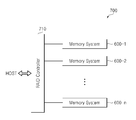
도 12와 도 13을 참조하면, RAID(redundant array of independent disks) 시스템으로 구현될 수 있는 데이터 처리 시스템(700)은 RAID 컨트롤러(710)와 다수의 전자 장치들(600-1~600-n; n는 자연수)을 포함할 수 있다.12 and 13, a
다수의 전자 장치들(600-1~600-n) 각각은 도 12에 도시된 전자 장치(600), 예컨대 메모리 시스템일 수 있다. 다수의 전자 장치들(600-1~600-n)은 RAID 어레이를 구성할 수 있다. 데이터 처리 시스템(700)은 PC(personal computer) 또는 SSD로 구현될 수 있다.Each of the plurality of electronic devices 600-1 to 600-n may be the
프로그램 동작 동안, RAID 컨트롤러(710)는 호스트(HOST)로부터 출력된 프로그램 명령에 따라 호스트(HOST)로부터 출력된 프로그램 데이터를 RAID 레벨에 따라 다수의 전자 장치들(600-1~600-n) 중에서 적어도 어느 하나의 전자 장치로 출력할 수 있다.During the program operation, the
리드 동작 동안, RAID 컨트롤러(710)는 호스트(HOST)로부터 출력된 리드 명령에 따라 다수의 전자 장치들(600-1~600-n) 중에서 적어도 어느 하나의 전자 장치로부터 읽혀진 데이터를 호스트(HOST)로 전송할 수 있다.During the read operation, the
본 발명은 도면에 도시된 실시 예를 참고로 설명되었으나 이는 예시적인 것에 불과하며, 본 기술 분야의 통상의 지식을 가진 자라면 이로부터 다양한 변형 및 균등한 타 실시 예가 가능하다는 점을 이해할 것이다. 따라서, 본 발명의 진정한 기술적 보호 범위는 첨부된 등록청구범위의 기술적 사상에 의해 정해져야 할 것이다.While the present invention has been particularly shown and described with reference to exemplary embodiments thereof, it is evident that many alternatives, modifications and variations will be apparent to those skilled in the art. Accordingly, the true scope of the present invention should be determined by the technical idea of the appended claims.
10: 메모리 시스템
20: 호스트
30: 메모리 컨트롤러
30-1: 마이크로프로세서
30-2: 실시간 클락 회로
30-3: 카운터
30-4: ROM(read only memory)
30-5: RAM(random access memory)
30-6: 호스트 인터페이스
30-7: NAND 인터페이스
40: 불휘발성 메모리10: Memory system
20: Host
30: Memory controller
30-1: Microprocessor
30-2: Real-time clock circuit
30-3: Counter
30-4: ROM (read only memory)
30-5: random access memory (RAM)
30-6: Host interface
30-7: NAND Interface
40: nonvolatile memory
Claims (10)
상기 저장 영역에 프로그램된 상기 데이터에 대한 리드 동작이 수행될 때 상기 불휘발성 메모리로부터 읽혀진 상기 제1RTC 값과 상기 리드 동작이 수행된 시각을 지시하는 제2RTC 값을 이용하여 상기 저장 영역에 대한 정보를 획득하는 단계; 및
상기 저장 영역에 대한 리드 리트라이 동작이 수행될 때 상기 정보를 이용하여 상기 리드 리트라이 동작의 최대 회수를 제어하는 단계를 포함하는 메모리 컨트롤러의 동작 방법.A first real time clock (RTC) value indicating a time-of-day at which the program operation is performed when a program operation for programming data in a non-volatile memory storage area is performed, Programming into a volatile memory;
Volatile memory and a second RTC value indicating a time at which the read operation is performed when the read operation is performed on the data programmed in the storage area, Obtaining; And
And controlling the maximum number of read retry operations using the information when the read retry operation is performed on the storage area.
상기 메모리 컨트롤러가 부팅(booting)될 때 호스트로부터 출력된 부팅 시각을 지시하는 부팅 RTC 값을 카운터를 이용하여 생성하는 단계; 및
상기 부팅 RTC 값을 상기 카운터를 이용하여 상기 제1RTC 값과 상기 제2RTC 값 각각으로 업-데이트하는 단계를 더 포함하는 메모리 컨트롤러의 동작 방법.The method according to claim 1,
Generating a boot RTC value indicating a boot time output from the host by using a counter when the memory controller is booted; And
Further comprising: up-dating the boot RTC value to the first RTC value and the second RTC value using the counter, respectively.
상기 제2RTC 값과 상기 제1RTC 값의 차이를 이용하여 상기 정보를 획득하는 메모리 컨트롤러의 동작 방법.2. The method of claim 1, wherein obtaining the information comprises:
And acquiring the information using a difference between the second RTC value and the first RTC value.
상기 제1RTC 값과 상기 제2RTC 값 각각은 상기 메모리 컨트롤러가 부팅될 때 호스트로부터 출력된 부팅 시각을 나타내는 부팅 RTC 값으로부터 상기 실시간 클락 회로에 의하여 업-데이트된 값인 메모리 컨트롤러의 동작 방법.5. The method of claim 4,
Wherein each of the first RTC value and the second RTC value is a value up-dated by the real time clock circuit from a boot RTC value indicating a boot time output from the host when the memory controller is booted.
상기 리드 리트라이 동작의 상기 최대 회수를 감소시키는 메모리 컨트롤러의 동작 방법.2. The method of claim 1, wherein the step of controlling the read retry operation comprises:
And decreasing the maximum number of times of the read retry operation.
상기 리드 리트라이 동작에 필요한 초기 리드 전압 레벨을 제어하기 위한 제어 신호를 상기 불휘발성 메모리로 전송하는 메모리 컨트롤러의 동작 방법.2. The method of claim 1, wherein the step of controlling the read retry operation comprises:
And a control signal for controlling an initial read voltage level necessary for the read retry operation is transmitted to the nonvolatile memory.
상기 불휘발성 메모리의 동작을 제어하는 메모리 컨트롤러를 포함하며,
상기 메모리 컨트롤러는,
상기 저장 영역에 대한 리드 동작 동안, 상기 저장 영역에 대해 프로그램 동작이 수행된 제1시각과 상기 저장 영역에 대해 상기 리드 동작이 수행된 제2시각의 차이를 계산하고 계산 결과에 따라 상기 저장 영역에 대한 리드 리트라이 동작의 최대 회수를 제어하는 메모리 시스템.A nonvolatile memory including a storage area; And
And a memory controller for controlling the operation of the nonvolatile memory,
The memory controller includes:
A difference between a first time at which a program operation is performed to the storage area and a second time at which the read operation is performed to the storage area is calculated during a read operation for the storage area, And the maximum number of read retry operations is controlled.
클락 신호에 응답하여 제1실시간 클락(real time clock(RTC)) 값과 제2RTC 값을 생성하는 실시간 클락(RTC) 회로; 및
상기 제1시각을 지시하는 상기 제1RTC 값을 상기 불휘발성 메모리로의 프로그램을 제어하고, 상기 리드 동작이 수행될 때 상기 불휘발성 메모리로부터 읽혀진 상기 제1RTC 값과 상기 제2시각을 지시하는 상기 제2RTC 값을 이용하여 상기 차이를 계산하고, 상기 리트라이 동작이 수행될 때 상기 차이를 이용하여 상기 리드 리트라이 동작의 상기 최대 회수의 감소를 제어하는 마이크로프로세서를 포함하는 메모리 시스템.The memory controller according to claim 8,
A real time clock (RTC) circuit responsive to a clock signal for generating a first real time clock (RTC) value and a second RTC value; And
Volatile memory for controlling the program to the nonvolatile memory to store the first RTC value indicative of the first time, and a second RTC value indicating the first RTC value and the second time read from the nonvolatile memory when the read operation is performed, Calculating a difference using a 2RTC value, and controlling the decrease in the maximum number of read retry operations using the difference when the retry operation is performed.
상기 클락 신호에 응답하여 상기 제1RTC 값과 상기 제2TRC 값을 생성하기 위한 카운터를 포함하는 메모리 시스템.10. The RTC circuit as claimed in claim 9,
And a counter for generating the first RTC value and the second TRC value in response to the clock signal.
Priority Applications (2)
| Application Number | Priority Date | Filing Date | Title |
|---|---|---|---|
| KR1020110077748A KR101826140B1 (en) | 2011-08-04 | 2011-08-04 | Method for operating memory controller, and memory system having the same |
| US13/564,076 US8990535B2 (en) | 2011-08-04 | 2012-08-01 | Method for operating memory controller, and memory system including the same |
Applications Claiming Priority (1)
| Application Number | Priority Date | Filing Date | Title |
|---|---|---|---|
| KR1020110077748A KR101826140B1 (en) | 2011-08-04 | 2011-08-04 | Method for operating memory controller, and memory system having the same |
Publications (2)
| Publication Number | Publication Date |
|---|---|
| KR20130015643A KR20130015643A (en) | 2013-02-14 |
| KR101826140B1 true KR101826140B1 (en) | 2018-03-22 |
Family
ID=47627709
Family Applications (1)
| Application Number | Title | Priority Date | Filing Date |
|---|---|---|---|
| KR1020110077748A Active KR101826140B1 (en) | 2011-08-04 | 2011-08-04 | Method for operating memory controller, and memory system having the same |
Country Status (2)
| Country | Link |
|---|---|
| US (1) | US8990535B2 (en) |
| KR (1) | KR101826140B1 (en) |
Cited By (2)
| Publication number | Priority date | Publication date | Assignee | Title |
|---|---|---|---|---|
| US11386965B2 (en) | 2019-05-16 | 2022-07-12 | SK Hynix Inc. | Memory device, memory system including the memory device, and operating method of the memory system |
| US11461177B2 (en) | 2020-03-06 | 2022-10-04 | SK Hynix Inc. | Data storage device and method of operating the same |
Families Citing this family (12)
| Publication number | Priority date | Publication date | Assignee | Title |
|---|---|---|---|---|
| CN103559140B (en) * | 2013-10-29 | 2016-07-20 | 深圳创维数字技术有限公司 | A kind of method for flash data storage and device |
| KR102258126B1 (en) * | 2015-03-19 | 2021-05-28 | 삼성전자주식회사 | Method of operating a memory controller, a data storage device including same, and data processing system including same |
| KR20170076883A (en) | 2015-12-24 | 2017-07-05 | 에스케이하이닉스 주식회사 | Memory system and operation method for the same |
| CN110246533B (en) * | 2018-03-09 | 2020-11-13 | 建兴储存科技(广州)有限公司 | Failure mode detection method and error correction method for solid-state storage device |
| US10990463B2 (en) | 2018-03-27 | 2021-04-27 | Samsung Electronics Co., Ltd. | Semiconductor memory module and memory system including the same |
| KR102549584B1 (en) * | 2018-03-27 | 2023-06-30 | 삼성전자주식회사 | Memory system including memory module, memory module, and operating method of memory module |
| KR102567314B1 (en) | 2018-04-27 | 2023-08-17 | 에스케이하이닉스 주식회사 | Memory system and operating method thereof |
| KR102590886B1 (en) | 2018-10-30 | 2023-10-19 | 에스케이하이닉스 주식회사 | Memory system and operating method thereof |
| KR102653661B1 (en) * | 2018-12-11 | 2024-04-03 | 에스케이하이닉스 주식회사 | Storage device and operating method thereof |
| TWI746927B (en) * | 2019-01-24 | 2021-11-21 | 慧榮科技股份有限公司 | Method for managing flash memory module and associated flash memory controller and electronic device |
| KR102653659B1 (en) * | 2019-07-05 | 2024-04-03 | 에스케이하이닉스 주식회사 | Memory system, memory controller, and operating method |
| US11023172B2 (en) * | 2019-07-26 | 2021-06-01 | Micron Technology, Inc. | Selecting read voltage using write transaction data |
Citations (4)
| Publication number | Priority date | Publication date | Assignee | Title |
|---|---|---|---|---|
| JP2003006051A (en) * | 2001-06-22 | 2003-01-10 | Matsushita Electric Ind Co Ltd | Electronic media access control system |
| WO2010074819A1 (en) | 2008-12-16 | 2010-07-01 | Sandisk Corporation | Controlled data access to non-volatile memory |
| US20110066899A1 (en) * | 2009-09-17 | 2011-03-17 | Samsung Electronics Co., Ltd. | Nonvolatile memory system and related method of performing erase refresh operation |
| KR101030385B1 (en) * | 2006-02-13 | 2011-04-20 | 삼성전자주식회사 | Booting device and method of system having only internal memory |
Family Cites Families (6)
| Publication number | Priority date | Publication date | Assignee | Title |
|---|---|---|---|---|
| GB2315887B (en) | 1996-07-27 | 2000-07-05 | Motorola Gmbh | Method and apparatus for re-programming memory device |
| JPH10254590A (en) | 1997-03-07 | 1998-09-25 | Seiko Epson Corp | Integrated circuit and information processing device |
| JPH1185571A (en) | 1997-09-03 | 1999-03-30 | Nec Corp | System for storing log into flash memory |
| US7770079B2 (en) | 2007-08-22 | 2010-08-03 | Micron Technology Inc. | Error scanning in flash memory |
| KR101626528B1 (en) * | 2009-06-19 | 2016-06-01 | 삼성전자주식회사 | Flash memory device and data read method thereof |
| US8819503B2 (en) * | 2010-07-02 | 2014-08-26 | Stec, Inc. | Apparatus and method for determining an operating condition of a memory cell based on cycle information |
-
2011
- 2011-08-04 KR KR1020110077748A patent/KR101826140B1/en active Active
-
2012
- 2012-08-01 US US13/564,076 patent/US8990535B2/en active Active
Patent Citations (4)
| Publication number | Priority date | Publication date | Assignee | Title |
|---|---|---|---|---|
| JP2003006051A (en) * | 2001-06-22 | 2003-01-10 | Matsushita Electric Ind Co Ltd | Electronic media access control system |
| KR101030385B1 (en) * | 2006-02-13 | 2011-04-20 | 삼성전자주식회사 | Booting device and method of system having only internal memory |
| WO2010074819A1 (en) | 2008-12-16 | 2010-07-01 | Sandisk Corporation | Controlled data access to non-volatile memory |
| US20110066899A1 (en) * | 2009-09-17 | 2011-03-17 | Samsung Electronics Co., Ltd. | Nonvolatile memory system and related method of performing erase refresh operation |
Cited By (2)
| Publication number | Priority date | Publication date | Assignee | Title |
|---|---|---|---|---|
| US11386965B2 (en) | 2019-05-16 | 2022-07-12 | SK Hynix Inc. | Memory device, memory system including the memory device, and operating method of the memory system |
| US11461177B2 (en) | 2020-03-06 | 2022-10-04 | SK Hynix Inc. | Data storage device and method of operating the same |
Also Published As
| Publication number | Publication date |
|---|---|
| US8990535B2 (en) | 2015-03-24 |
| US20130036261A1 (en) | 2013-02-07 |
| KR20130015643A (en) | 2013-02-14 |
Similar Documents
| Publication | Publication Date | Title |
|---|---|---|
| KR101826140B1 (en) | Method for operating memory controller, and memory system having the same | |
| US8615702B2 (en) | Method and apparatus for correcting errors in memory device | |
| US9773565B1 (en) | Memory retry-read method, memory storage device and memory control circuit unit | |
| US10782920B2 (en) | Data access method, memory storage apparatus and memory control circuit unit | |
| KR102350644B1 (en) | Memory controller and memory system having the same | |
| KR102002385B1 (en) | Operating method for data storage device | |
| US11635777B2 (en) | Temperature control circuit, memory storage device and temperature control method | |
| KR20100093739A (en) | Method of reading data in a non-volatile memory device | |
| KR20120035064A (en) | Method for changing read parameter for improving read performance and apparatuses using the same | |
| US9472300B2 (en) | Data storage device and operating method thereof | |
| US10528264B2 (en) | Storage device and data processing system including the same | |
| KR20190090268A (en) | Memory controller and memory system having the same | |
| KR20210087247A (en) | Memory system and operating method thereof | |
| KR102415218B1 (en) | Memory system and operation method thereof | |
| CN111105833B (en) | Memory device, memory system and method of operating a memory system | |
| TW201835753A (en) | Data programming method, memory storage device and memory control circuit unit | |
| US8276033B2 (en) | Data writing method for a flash memory, and flash memory controller and flash memory storage apparatus using the same | |
| US11449422B2 (en) | Memory controller and operating method thereof | |
| US8583855B2 (en) | Flash memory preprocessing system and method | |
| US8914572B2 (en) | Memory controllers and memory systems including the same | |
| US8924635B2 (en) | Memory controller and method of operating the same, and memory system including the same | |
| US20260072598A1 (en) | Memory device, operation method of memory device, memory system, and chip | |
| KR20260024151A (en) | Apparatus and method for supporting effective read operation | |
| CN117908761A (en) | Data storage device and write buffer management method | |
| CN117950573A (en) | Data storage device and write buffer management method |
Legal Events
| Date | Code | Title | Description |
|---|---|---|---|
| PA0109 | Patent application |
St.27 status event code: A-0-1-A10-A12-nap-PA0109 |
|
| R18-X000 | Changes to party contact information recorded |
St.27 status event code: A-3-3-R10-R18-oth-X000 |
|
| PG1501 | Laying open of application |
St.27 status event code: A-1-1-Q10-Q12-nap-PG1501 |
|
| A201 | Request for examination | ||
| PA0201 | Request for examination |
St.27 status event code: A-1-2-D10-D11-exm-PA0201 |
|
| D13-X000 | Search requested |
St.27 status event code: A-1-2-D10-D13-srh-X000 |
|
| D14-X000 | Search report completed |
St.27 status event code: A-1-2-D10-D14-srh-X000 |
|
| E902 | Notification of reason for refusal | ||
| PE0902 | Notice of grounds for rejection |
St.27 status event code: A-1-2-D10-D21-exm-PE0902 |
|
| E701 | Decision to grant or registration of patent right | ||
| PE0701 | Decision of registration |
St.27 status event code: A-1-2-D10-D22-exm-PE0701 |
|
| PR0701 | Registration of establishment |
St.27 status event code: A-2-4-F10-F11-exm-PR0701 |
|
| PR1002 | Payment of registration fee |
St.27 status event code: A-2-2-U10-U11-oth-PR1002 Fee payment year number: 1 |
|
| PG1601 | Publication of registration |
St.27 status event code: A-4-4-Q10-Q13-nap-PG1601 |
|
| PR1001 | Payment of annual fee |
St.27 status event code: A-4-4-U10-U11-oth-PR1001 Fee payment year number: 4 |
|
| PR1001 | Payment of annual fee |
St.27 status event code: A-4-4-U10-U11-oth-PR1001 Fee payment year number: 5 |
|
| PR1001 | Payment of annual fee |
St.27 status event code: A-4-4-U10-U11-oth-PR1001 Fee payment year number: 6 |
|
| PR1001 | Payment of annual fee |
St.27 status event code: A-4-4-U10-U11-oth-PR1001 Fee payment year number: 7 |
|
| PR1001 | Payment of annual fee |
St.27 status event code: A-4-4-U10-U11-oth-PR1001 Fee payment year number: 8 |
|
| PR1001 | Payment of annual fee |
St.27 status event code: A-4-4-U10-U11-oth-PR1001 Fee payment year number: 9 |
|
| U11 | Full renewal or maintenance fee paid |
Free format text: ST27 STATUS EVENT CODE: A-4-4-U10-U11-OTH-PR1001 (AS PROVIDED BY THE NATIONAL OFFICE) Year of fee payment: 9 |