KR101789163B1 - A stereo-scopic image viewer for portable device - Google Patents
A stereo-scopic image viewer for portable device Download PDFInfo
- Publication number
- KR101789163B1 KR101789163B1 KR1020160034881A KR20160034881A KR101789163B1 KR 101789163 B1 KR101789163 B1 KR 101789163B1 KR 1020160034881 A KR1020160034881 A KR 1020160034881A KR 20160034881 A KR20160034881 A KR 20160034881A KR 101789163 B1 KR101789163 B1 KR 101789163B1
- Authority
- KR
- South Korea
- Prior art keywords
- shaft assembly
- partition
- shaft
- assembly
- hinge
- Prior art date
- Legal status (The legal status is an assumption and is not a legal conclusion. Google has not performed a legal analysis and makes no representation as to the accuracy of the status listed.)
- Expired - Fee Related
Links
Images


Classifications
-
- H04N13/0409—
-
- H—ELECTRICITY
- H04—ELECTRIC COMMUNICATION TECHNIQUE
- H04N—PICTORIAL COMMUNICATION, e.g. TELEVISION
- H04N13/00—Stereoscopic video systems; Multi-view video systems; Details thereof
- H04N13/30—Image reproducers
- H04N13/302—Image reproducers for viewing without the aid of special glasses, i.e. using autostereoscopic displays
- H04N13/31—Image reproducers for viewing without the aid of special glasses, i.e. using autostereoscopic displays using parallax barriers
-
- G02B27/22—
-
- G—PHYSICS
- G02—OPTICS
- G02B—OPTICAL ELEMENTS, SYSTEMS OR APPARATUS
- G02B30/00—Optical systems or apparatus for producing three-dimensional [3D] effects, e.g. stereoscopic images
-
- H04N13/042—
-
- H—ELECTRICITY
- H04—ELECTRIC COMMUNICATION TECHNIQUE
- H04N—PICTORIAL COMMUNICATION, e.g. TELEVISION
- H04N13/00—Stereoscopic video systems; Multi-view video systems; Details thereof
- H04N13/30—Image reproducers
- H04N13/302—Image reproducers for viewing without the aid of special glasses, i.e. using autostereoscopic displays
- H04N13/322—Image reproducers for viewing without the aid of special glasses, i.e. using autostereoscopic displays using varifocal lenses or mirrors
Landscapes
- Physics & Mathematics (AREA)
- Engineering & Computer Science (AREA)
- Multimedia (AREA)
- Signal Processing (AREA)
- General Physics & Mathematics (AREA)
- Optics & Photonics (AREA)
Abstract
축 어셈블리; 상기 축 어셈블리를 중심으로 축 회동하여 열리거나 닫혀지는 렌즈부; 상기 축 어셈블리에 고정 결합되며, 휴대 단말기의 화면으로부터 소정 거리를 유지시키는 격벽부; 및 상기 격벽부에 결합되며 상기 축 어셈블리의 축 방향으로 왕복 이동하는 거치부;를 포함하는 휴대 단말기용 입체 영상 뷰어를 제공한다.Axis assembly; A lens unit which is pivotally opened and closed about the axis assembly; A partition wall fixedly coupled to the shaft assembly to maintain a predetermined distance from a screen of the portable terminal; And a mounting part coupled to the partition part and reciprocating in the axial direction of the shaft assembly.
Description
본 발명은 휴대 단말기용 입체 영상 뷰어에 관한 것으로서, 보다 상세하게는 스마트폰 등 휴대 단말기에서 실행되는 2차원 영상을 입체(3차원) 영상으로 시청할 수 있는 휴대 단말기용 입체 영상 뷰어에 관한 것이다.The present invention relates to a stereoscopic image viewer for a mobile terminal, and more particularly, to a stereoscopic image viewer for a mobile terminal capable of viewing a two-dimensional image, which is executed in a mobile terminal such as a smart phone, as a stereoscopic image.
최근 출시되는 스마트폰 등의 휴대 단말기는 단순히 전화, 문자 등의 기능 뿐만 아니라 멀티미디어를 재생할 수 있을 정도로 화면이 커지고 하드웨어 성능이 향상되었다.Recently, mobile phones such as smart phones have not only functions such as telephone and text, but also have improved screen performance and hardware performance so that multimedia can be played.
휴대 단말기에서 멀티미디어 동영상의 재생은 그 사용 빈도가 증대되고 있으며 특히 동영상 중 입체감을 살려 시청자에게 전달하는 입체 동영상은 영화, TV 등 다양한 분야에서 사용되고 있다.The frequency of use of the multimedia video in the portable terminal is increasing. In particular, the stereoscopic video transmitted to the viewer by utilizing the stereoscopic effect of the video is used in various fields such as movies and TV.
그러나, 휴대용 단말기에서 입체 영상을 시청하기 위해서는 시청자의 양안에 별도의 영상을 전달하기 위한 편광 안경이나 셔터 기능이 있는 안경이 제공되어야 한다. 그러나, 편광 안경에 맞춰 동영상을 제공하기 위해서는 휴대 단말기의 하드웨어가 지원되어야 하기 때문에 확산이 쉽지 않은 실정이다. 또한 셔터 기능이 있는 안경을 사용하는 경우에도 별도의 전원 공급이 필요하고 셔터를 구현하기 위한 별도 장치가 더 구비되어야 하므로 단가가 비싸고 부피가 증대된다는 점에서 휴대 단말기에 적용하기가 쉽지 않다.However, in order to view a stereoscopic image in a portable terminal, polarizing glasses or glasses having a shutter function must be provided for transmitting separate images to both sides of a viewer. However, in order to provide moving images in accordance with polarized glasses, it is not easy to spread because the hardware of the portable terminal must be supported. Further, even when using glasses having a shutter function, it is not easy to apply the power supply to the portable terminal because a separate power supply is required and a separate device for realizing the shutter is required, so that the unit price is high and the volume is increased.
본 발명의 실시예는 상기와 같은 문제점을 해결하기 위해 안출된 것으로서, 휴대 및 사용하기 편리한 구조를 갖는 휴대 단말기용 입체 영상 뷰어를 제공하고자 한다.SUMMARY OF THE INVENTION The present invention has been made to solve the above problems, and it is an object of the present invention to provide a stereoscopic image viewer for a portable terminal having a portable and easy to use structure.
또한, 입체 영상 뷰어는 휴대 단말기의 화면을 통해 실행되는 좌우 영상 사이에 서로 간섭이 발생되지 않도록 한다. 또한, 입체 영상 뷰어의 각 구성 요소는 서로 견고하게 결합되어 반복적인 사용에 대한 내구성과 외부 충격 등에 쉽게 파손되지 않는 것을 목적으로 한다.In addition, the stereoscopic image viewer prevents interference between left and right images executed through the screen of the portable terminal. In addition, each component of the stereoscopic image viewer is rigidly coupled to each other so that the stereoscopic image viewer is not easily damaged by repetitive use and external impact.
또한, 입체 영상 뷰어는 크기가 다른 타 종류의 휴대 단말기에도 사용할 수 있도록 호환성을 갖는 것을 목적으로 한다.In addition, the stereoscopic image viewer aims to have compatibility with other types of portable terminals having different sizes.
본 발명의 실시예는 상기와 같은 과제를 해결하고자, 축 어셈블리; 상기 축 어셈블리를 중심으로 축 회동하여 열리거나 닫혀지는 렌즈부; 상기 축 어셈블리에 고정 결합되며, 휴대 단말기의 화면으로부터 소정 거리를 유지시키는 격벽부; 및 상기 격벽부에 결합되며 상기 축 어셈블리의 축 방향으로 왕복 이동하는 거치부;를 포함하는 휴대 단말기용 입체 영상 뷰어를 제공한다.In order to solve the above-described problems, an embodiment of the present invention provides a shaft assembly, A lens unit which is pivotally opened and closed about the axis assembly; A partition wall fixedly coupled to the shaft assembly to maintain a predetermined distance from a screen of the portable terminal; And a mounting part coupled to the partition part and reciprocating in the axial direction of the shaft assembly.
상기 축 어셈블리는 힌지 샤프트; 상기 힌지 샤프트의 일 단에 회동 가능하게 결합되는 힌지 모듈; 및 상기 힌지 샤프트와 상기 힌지 모듈 사이에 축 방향으로 배치되는 스프링;을 포함할 수 있다.The shaft assembly includes a hinge shaft; A hinge module rotatably coupled to one end of the hinge shaft; And a spring disposed axially between the hinge shaft and the hinge module.
상기 힌지 모듈에는 내주면에 적어도 하나 이상의 구속 돌기가 형성될 수 있다.At least one restraining protrusion may be formed on the inner circumferential surface of the hinge module.
상기 힌지 샤프트에는 일 단에 상기 힌지 모듈의 축 회동을 안내하는 회동 안내부가 형성되며, 상기 회동 안내부에는 상기 축 회동을 구속하는 걸림 턱이 형성될 수 있다. The hinge shaft is provided at one end thereof with a rotation guide portion for guiding axial rotation of the hinge module, and the rotation guide portion may be formed with a locking protrusion for restricting the rotation of the shaft.
상기 렌즈부는 렌즈 프레임; 및 상기 렌즈 프레임의 일 측에 형성되어 상기 축 어셈블리와 결합되는 한 쌍의 고리형 부재;를 더 포함하고, 상기 고리형 부재 중 어느 하나의 내주면에는 상기 축 어셈블리와 고정 결합되게 하는 고정면이 형성될 수 있다.The lens unit includes a lens frame; And a pair of annular members formed on one side of the lens frame and coupled to the shaft assembly, wherein a fixing surface for fixing the fixing assembly to the shaft assembly is formed on an inner circumferential surface of one of the annular members .
상기 격벽부는 격벽 플레이트; 및 상기 격벽 플레이트의 일 측에 형성되는 상기 축 어셈블리와 고정 결합되는 원통형 부재;를 더 포함할 수 있다.The partition wall portion includes a partition plate; And a cylindrical member fixedly coupled to the shaft assembly formed on one side of the partition plate.
상기 격벽 플레이트에는 내측면에 상기 거치부가 상기 축 방향으로 이동하도록 안내하는 적어도 하나 이상의 가이드 돌기가 형성될 수 있다.At least one guide protrusion may be formed on the inner surface of the partition plate so as to guide the mounting portion to move in the axial direction.
상기 격벽부는 벽 플레이트; 및 기 격벽 플레이트의 일 측에 형성되는 상기 축 어셈블리와 고정 결합되는 원통형 부재;를 더 포함하고, 기 원통형 부재에는 내주면에 상기 힌지 샤프트가 고정 결합되게 하는 적어도 하나 이상의 고정 리브와, 상기 고정 리브와 평행하게 배치되며 상기 원통형 부재의 내측 공간을 양분하는 분할 리브가 각각 형성될 수 있다.The partition wall portion includes a wall plate; And a cylindrical member fixedly coupled to the shaft assembly formed at one side of the base bulkhead plate, wherein the cylindrical member has at least one fixed rib for fixing the hinge shaft to the inner circumferential surface thereof, And partition ribs that are disposed in parallel and bisect the inner space of the cylindrical member may be respectively formed.
상기 거치부는 기 격벽부의 내부에서 왕복 슬라이딩 이동하는 슬라이드 몸체; 기 슬라이드 몸체와 수직하게 형성되는 그립 부재; 기 슬라이드 몸체의 이동 방향과 나란하게 상기 슬라이드 몸체에 형성되는 슬롯 홀; 기 슬라이드 몸체에서 연장 형성되는 톱니 레일부;를 포함할 수 있다. A slide body that reciprocally slides within the barrier rib; A grip member formed perpendicular to the base slide body; A slot hole formed in the slide body to be parallel to a moving direction of the slide body; And a toothed rail part extending from the base slide body.
상기 격벽부는 상기 톱니 레일부와 맞물리도록 결합되는 기어부;를 더 포함하며, 기 기어부에는 상기 거치부가 서로 멀어지면 복원력을 제공하는 탄성 코일이 결합될 수 있다.The partition portion may further include a gear portion that is engaged with the toothed rail portion, and an elastic coil that provides a restoring force may be coupled to the gear portion when the to-be-installed portion is distant from the toothed portion.
이상에서 살펴본 바와 같은 본 발명의 과제해결 수단에 의하면 다음과 같은 사항을 포함하는 다양한 효과를 기대할 수 있다. 다만, 본 발명이 하기와 같은 효과를 모두 발휘해야 성립되는 것은 아니다.As described above, according to the present invention, various effects including the following can be expected. However, the present invention does not necessarily achieve the following effects.
본 발명의 일 실시예에 따른 입체 영상 뷰어는 격벽부를 사이에 두고 렌즈부가 회동하여 접힐 수 있으며 거치부는 격벽부의 내부 공간으로 이동할 수 있어 휴대하기 용이하다.The stereoscopic image viewer according to an embodiment of the present invention can fold the lens unit with the partition wall interposed therebetween and is easy to carry because the mount can move to the inner space of the partition wall.
또한, 렌즈부는 한 쌍으로 이루어진 축 어셈블리에 결합되어 각각 독립적으로 회동할 수 있으며, 축 어셈블리를 구성하는 힌지 샤프트와 힌지 모듈의 특징적인 형상 및 그 사이에 배치되는 스프링에 의해 렌즈부는 소정 토크가 가해질 때 열리거나 닫혀질 수 있다.In addition, the lens unit can be coupled to the pair of axle assemblies to pivot independently of each other, and the lens unit is subjected to a predetermined torque by the characteristic shape of the hinge shaft and the hinge module constituting the axis assembly, It can be opened or closed.
또한, 격벽부에 의해 휴대 단말기는 화면이 좌우 영역으로 구분, 차단되어 각 영역을 통해 실행되는 영상 사이에 간섭 현상이 발생하지 않는다.In addition, due to the partition, the screen of the portable terminal is divided into left and right regions, so that interference does not occur between the images executed through the respective regions.
또한, 격벽부에 형성되는 적어도 하나 이상의 고정 리브로 인해 내구성을 보다 향상시킬 수 있으며, 축 어셈블리와 보다 견고하게 결합될 수 있다.Further, the durability can be further improved by at least one fixed rib formed in the partition wall portion, and can be more firmly coupled to the shaft assembly.
또한, 거치부는 휴대 단말기의 크기에 따라 축 방향으로 이격 거리의 조절 가능한 바, 호환성이 높아 타 종류의 휴대 단말기에도 사용할 수 있다.In addition, the mounting portion is adjustable in the axial direction according to the size of the portable terminal, and the mounting portion is highly compatible and can be used in other types of portable terminals.
또한, 거치부는 이격 거리를 조절할 때 서로 연동하여 동일하게 움직이도록 형성되어 휴대 단말기에 고정시키는 것이 용이하다.Further, when the spacing distance is adjusted, it is easy for the mounting part to be fixed to the portable terminal.
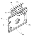
도 1은 본 발명의 일 실시예에 따른 입체 영상 뷰어의 사시도.
도 2는 도 1의 입체 영상 뷰어를 휴대 단말기에 고정시킨 상태를 도시한 사시도.
도 3은 도 1의 축 어셈블리에 대한 분해 사시도.
도 4는 도 1의 축 어셈블리를 단면 처리한 사시도.
도 5는 도 3의 힌지 샤프트를 도시한 사시도.
도 6은 도 3의 힌지 모듈을 도시한 사시도.
도 7은 도 2의 렌즈부의 절개 사시도.
도 8은 도 2의 격벽부의 내측면을 도시한 사시도.
도 9는 축 어셈블리와 격벽부 사이의 결합 구조를 도시한 절개 사시도.
도 10은 거치부 사이의 거리가 최소일 때의 분해 사시도.
도 11은 거치부 사이의 거리가 최대일 때의 분해 사시도.1 is a perspective view of a stereoscopic image viewer according to an embodiment of the present invention;
FIG. 2 is a perspective view illustrating a state where the stereoscopic image viewer of FIG. 1 is fixed to a portable terminal.
3 is an exploded perspective view of the shaft assembly of FIG.
Figure 4 is a perspective view of the shaft assembly of Figure 1 sectioned.
Fig. 5 is a perspective view showing the hinge shaft of Fig. 3; Fig.
FIG. 6 is a perspective view showing the hinge module of FIG. 3; FIG.
FIG. 7 is an exploded perspective view of the lens portion of FIG. 2; FIG.
8 is a perspective view showing an inner side surface of the partition wall portion of Fig.
9 is an exploded perspective view showing a coupling structure between the shaft assembly and the partition wall portion;
10 is an exploded perspective view when the distance between the mounting portions is minimum;
11 is an exploded perspective view when the distance between the mounting portions is maximum;
이하, 도면을 참조하여 본 발명의 구체적인 실시예를 상세히 설명한다.Hereinafter, specific embodiments of the present invention will be described in detail with reference to the drawings.
도 1은 본 발명의 일 실시예에 따른 입체 영상 뷰어의 사시도이고, 도 2는 도 1의 입체 영상 뷰어를 휴대 단말기에 고정시킨 상태를 도시한 사시도이다. 도 1 및 도 2를 참조하면 휴대 단말기용 입체 영상 뷰어는 축 어셈블리(10), 렌즈부(20), 격벽부(30) 및 거치부(40)를 포함할 수 있다.FIG. 1 is a perspective view of a stereoscopic image viewer according to an exemplary embodiment of the present invention, and FIG. 2 is a perspective view illustrating a stereoscopic image viewer of FIG. 1 fixed to a mobile terminal. 1 and 2, the stereoscopic image viewer for a portable terminal may include a
여기서, 휴대 단말기는 개인이 휴대하면서 통신을 하거나 혹은 정보를 관리할 수 있는 장치를 말하는 것으로서 스마트 폰, 휴대폰, PDA 등을 포함한다.Here, the portable terminal refers to a device capable of communicating or managing information while being carried by an individual, and includes a smart phone, a mobile phone, a PDA, and the like.
일 실시예에 따른 입체 영상 뷰어는 미사용 상태에서 렌즈부(20)가 축 회동하여 격벽부(30)를 수용하면서 닫혀지고, 거치부(40)가 격벽부(30)의 내부 공간으로 슬라이딩 삽입되면서 전체적으로 휴대하기 편리한 직육면체 형상의 외형을 갖는다.The stereoscopic image viewer according to the embodiment is configured such that the
반면, 사용자가 입체 영상 뷰어를 사용하기 위해서는 먼저 렌즈부(20)를 축 회동시켜 열리도록 한다. 이 때, 렌즈부(20)가 최대 열린 위치에서 렌즈부(20)와 격벽부(30)는 서로 수직하게 배치된다. 그 다음, 거치부(40)를 양 외측 방향으로 잡아당겨 축 어셈블리(10)의 축 방향으로 서로 멀어지도록 이동시킨 후 휴대 단말기의 측면에 결합하여 고정시킨다.On the other hand, in order to use the stereoscopic image viewer, the user first rotates the
도 3은 도 1의 축 어셈블리에 대한 분해 사시도이고, 도 4는 도 1의 축 어셈블리를 단면 처리한 사시도이며, 도 5는 도 3의 힌지 샤프트(12)를 도시한 사시도이며, 도 6은 도 3의 힌지 모듈(14)을 도시한 사시도이다. 도 3 내지 도 6을 참조하면, 축 어셈블리(10)는 힌지 샤프트(12), 힌지 모듈(14), 스프링(16) 및 힌지 캡(18)을 포함한다. 축 어셈블리(10)는 축 방향으로 일 직선으로 상호 대칭되도록 배치되는 한 쌍으로 이루어진다. 그 결과, 축 어셈블리(10)는 서로 독립적으로 회동할 수 있다.3 is an exploded perspective view of the shaft assembly of FIG. 1, FIG. 4 is a perspective view of the shaft assembly of FIG. 1, FIG. 5 is a perspective view of the
먼저, 힌지 샤프트(12)는 고정되어 있는 중심축에 해당된다. 이런, 힌지 샤프트(12)는 격벽부(30)와 고정 결합된다. 이를 위해, 힌지 샤프트(12)의 외주면에는 예를 들어, 평탄면으로 이루어지는 컷팅 평면(13)이 형성될 수 있다.First, the
또한, 힌지 샤프트(12)에는 힌지 모듈(14)의 축 회동을 구속 안내하는 회동 안내부(12a)가 형성된다. 회동 안내부(12a)는 힌지 모듈(14)이 축 방향으로 0도 내지 90도 이내 범위에서 축 회동할 수 있도록 소정 형상으로 형성될 수 있다. The
회동 안내부(12a)에는 축 회동을 구속하는 적어도 하나 이상의 걸림 턱(12b)이 형성될 수 있다. 걸림 턱(12b)은 힌지 모듈(14)이 소정 각도 회동하면 힌지 모듈(14)의 회동을 구속한다. 이 때, 힌지 모듈(14)은 가해지던 토크 이상의 토크가 가해져야 더 회동될 수 있다.The
또한, 회동 안내부(12a)에는 축 회동을 구속하는 적어도 하나 이상의 걸림 홈(12c)이 형성될 수 있다. 걸림 홈(12c)은 예를 들어 렌즈부(20)가 열리거나 닫혀지는 위치에 놓일 때 힌지 모듈(14)이 그 위치에서 걸림 상태를 유지할 수 있도록 한다.In addition, at least one
또한, 힌지 샤프트(12)에는 스프링(16)의 일 단이 고정 결합되게 하는 고정 돌기(15)가 더 형성될 수 있다.Further, the
다음으로 힌지 모듈(14)은 힌지 샤프트(12)의 일 단에 회동 가능하게 결합된다. 또한, 힌지 모듈(14)에는 내주면에 적어도 하나 이상의 구속 돌기(14a)가 형성될 수 있다. 구속 돌기(14a)는 힌지 모듈(14)이 힌지 샤프트(12)와의 상대적인 관계에서 축 회동할 때, 힌지 모듈(14)의 회동 동작을 구속한다. 즉, 구속 돌기(14a)는 회동 모듈의 회동 동작에 따라 회동 안내부(12a)의 형상에 구속되어 안내된다. 이 때, 구속 돌기(14a)의 형상은 다양하게 설계 변경 가능하다.Next, the
또한, 힌지 모듈(14)에는 힌지 샤프트(12)와 동일하게 스프링(16)의 타 단이 고정 결합되게 하는 고정 돌기(15)가 더 형성될 수 있다. 또한, 힌지 모듈(14)의 외주면에는 힌지 샤프트(12)와 비슷한 예를 들어 평탄면으로 이루어지는 컷팅 평면(13)이 적어도 하나 이상 형성된다.The
그리고, 스프링(16)은 힌지 샤프트(12)와 힌지 모듈(14) 사이에 축 방향으로 배치된다. 스프링(16)은 힌지 모듈(14)이 회동 안내부(12a)에 구속되면서 축 회동할 때, 힌지 모듈(14)이 축 방향으로 이동할 수 있도록 한다. 구체적으로 스프링(16)은 구속 돌기(14a)가 회동 안내부(12a)의 형상에 구속되어 원활하게 이동할 수 있도록 힌지 모듈(14)을 축 방향으로 이동시킬 수 있도록 탄성 복원력을 제공한다.Then, the
그리고, 힌지 캡(18)은 힌지 모듈(14)이 외부로 노출되는 것을 방지하기 위한 것으로 격벽부(30)에 본딩 등의 방법으로 고정 결합된다.The
일 실시예에 따른 렌즈부(20)는 렌즈부(20)가 그 자체의 무게에 의해 축 회동되어 열리거나 닫히지 않는다. 또한, 렌즈부(20)에는 열리거나 닫히는 과정에서 적어도 한 번 이상 걸림이 발생할 수 있다. 이 때, 걸림은 전술한 구속 돌기(14a)와 걸림 턱(12b)으로 인해 발생한다. 따라서, 렌즈부(20)가 이런 걸림을 극복하고 더 열리거나 더 닫혀지기 위해서는 더 큰 토크가 가해져야 한다.The
한편, 최대 열린 위치에서 렌즈부(20)는 일 직선으로 펼쳐진다. 걸림은 렌즈부(20)가 최대 열려 있는 위치에서 의도와 달리 쉽게 닫혀지는 것을 방지할 수 있다. 이처럼, 렌즈부(20)는 힌지 샤프트(12), 힌지 모듈(14) 및 스프링(16)에 의해 축 어셈블리(10)에 대해 소정 토크가 가해질 때 열리거나 닫힐 수 있다.On the other hand, the
도 7은 도 2의 렌즈부(20)의 절개 사시도이다. 도 7을 참조하면, 렌즈부(20)는 축 어셈블리(10)를 축으로 축 회동하는 대칭 형상의 한 쌍으로 이루어진다. 다만, 렌즈부(20)는 어느 한 쪽만이라도 독립적으로 열리거나 닫힐 수 있다. 구체적으로 렌즈부(20)는 렌즈(21), 렌즈 프레임(22), 고리형 부재(24) 및 고정면(26)을 포함한다.7 is a cutaway perspective view of the
렌즈(21)는 한 쌍으로 구성되며, 렌즈부(20)의 소정 위치에 각각 배치된다. 이 때, 렌즈(21)는 예를 들어 볼록렌즈를 사용할 수 있다. 볼록렌즈를 사용하는 이유는 분할된 각각의 영상 화면을 사용자의 좌안과 우안에 확대하여 비춰주기 위해서이다. 그리고, 렌즈(21)는 볼록한 면이 휴대 단말기를 향하도록 배치되는 것이 바람직하다. 그 결과, 사용자는 해당 영상 화면 이외에 다른 부분을 볼 수 없게 되어 입체 영상 뷰어를 통해 하나의 완성된 입체 화면을 인식할 수 있게 된다. The
렌즈부(20)는 플라스틱 재질의 렌즈 프레임(22)을 갖는다. 이러한 렌즈 프레임(22)은 직육면체 형상으로 이루어질 수 있다. 그리고, 전술한 렌즈(21)는 렌즈 프레임(22)에 고정 결합될 수 있다. 이와 달리, 렌즈(21)는 렌즈 프레임(22) 내에서 그 위치가 가변적일 수 있다.The
즉, 렌즈(21)는 그 사이의 이격 거리가 조절될 수 있다. 이는 사용자의 양안 사이의 간격에 대응하여 어떤 사용자라도 입체 영상 뷰어를 통해 입체 영상 화면을 감상할 수 있도록 하기 위함이다. 이를 위해, 렌즈 프레임(22)과 각 렌즈(21)의 결합 부위에는 예를 들어 슬라이딩 구조 등이 형성될 수 있다. 그 결과, 렌즈(21)는 렌즈 프레임(22)에 배치된 상태에서 왕복 이동할 수 있다.That is, the distance between the
그리고, 고리형 부재(24)는 렌즈 프레임(22)의 일 측에 적어도 하나 이상 형성되어 축 어셈블리(10)와 결합된다. 한편, 고리형 부재(24)는 축 어셈블리(10)를 축으로 회동하는 점에 비추어 링 형상을 갖는 것이 바람직하다.At least one
고리형 부재(24) 중 어느 하나의 내주면에는 축 어셈블리(10)와 고정 결합되게 하는 고정면(26)이 형성될 수 있다. 구체적으로 고정면(26)은 힌지 모듈(14)에 형성되는 컷팅 평면(13)과 접촉면이 형성되도록 결합되어 렌즈부(20)의 축 회동에 연동하여 힌지 모듈(14)이 동작할 수 있도록 한다.A fixing
이 때, 나머지 고리형 부재(24)는 렌즈부(20)가 축 회동할 때, 렌즈부(20)가 흔들리거나 흔들림에 의해 삐걱거리는 것을 방지한다. 또한, 축 회동 과정에서 렌즈부(20)에 가해지는 토크를 분산하여 고리형 부재(24)가 쉽게 파손되는 것을 방지할 수 있다.At this time, the remaining
또한, 렌즈 프레임(22)은 자성체(28)를 더 포함할 수 있다. 이는, 렌즈부(20)가 닫힌 상태에서 각 자성체(28)의 자기 결합에 따라 렌즈부(20)가 쉽게 열리는 것을 방지할 수 있도록 한다.Further, the
다음으로 격벽부(30)는 일 측이 축 어셈블리(10)에 고정 결합된다. 그리고, 격벽부(30)의 타 측은 휴대 단말기의 화면 창에 접촉되어 고정된다. 이를 위해, 격벽부(30)의 타 측면에는 회면 창과 접촉될 때 슬립이 발생하지 않도록 고무층 등이 형성될 수 있다. 격벽부(30)는 렌즈부(20)가 휴대 단말기의 화면으로부터 소정 거리를 유지할 수 있도록 한다. 동시에, 격벽부(30)는 휴대 단말기의 화면을 2분할시킬 수 있다.Next, the
입체 영상을 시청하기 위해 휴대 단말기에는 전용 어플리케이션이 설치되어야 한다. 이 때, 전용 어플리케이션은 동영상 파일을 실행할 때 휴대 단말기의 화면을 보는 방향에 따라 즉 가로 또는 세로 방향으로 2분할시킨다. 그 결과, 전용 어플리케이션을 통해 동영상 파일이 구동되는 휴대 단말기의 화면에는 중간에 어떤 영상도 제공되지 않는 선 형태의 경계 영역이 형성된다. 따라서, 사용자는 렌즈부(20)의 각 렌즈(21)를 통해 화면 영상을 볼 때 격벽부(30)에 의해 서로 다른 쪽의 화면을 전혀 볼 수 없게 된다.In order to view the stereoscopic image, a dedicated application must be installed in the portable terminal. At this time, the dedicated application divides the video file into two in the horizontal or vertical direction according to the viewing direction of the screen of the portable terminal when executing the video file. As a result, a line-shaped boundary area in which no image is provided in the middle is formed on the screen of the portable terminal in which the moving picture file is driven through the dedicated application. Accordingly, when the user views the screen image through each
도 8은 도 2의 격벽부(30)의 내측면을 도시한 사시도이고, 도 9는 축 어셈블리(10)와 격벽부(30) 사이의 결합 구조를 도시한 절개 사시도이다. 도 8 및 도 9를 참조하면, 격벽부(30)는 격벽 플레이트(32) 및 원통형 부재(34)를 포함한다. 이러한 격벽부(30)는 대칭 관계의 반 쪽 형상을 서로 접합하여 제조될 수 있다. 따라서, 격벽부(30)는 반 쪽 형상에 대한 설명만으로 나머지 반 쪽에 대한 설명을 생략할 수 있다.FIG. 8 is a perspective view showing an inner side surface of the
격벽 플레이트(32)는 전술한 것처럼 예를 들어, 좌안을 통해서 보게 되는 영상 화면이 우안으로 보게 되는 영상 화면으로부터 어떤 영향도 받지 않도록 형성된다. 즉, 좌측 화면에서 발생되는 빛이 우측 방향으로 전달되는 것을 차단할 수 있다. 따라서, 격벽 플레이트(32)는 비투명 재질로 형성하는 것이 바람직하다. The
또한, 격벽 플레이트(32)에는 내측면에 거치부(40)를 축 방향으로 이동 안내하는 적어도 하나 이상의 가이드 돌기(36)가 형성될 수 있다. 가이드 돌기(36)는 적어도 하나 이상의 원형 돌기(36a)와 선형 레일 돌기(36b) 등을 포함한다.Also, at least one guide protrusion 36 may be formed on the inner surface of the
또한, 격벽 플레이트(32)는 내측면 중앙에 거치부(40)가 서로 반대 방향으로 연동하도록 하는 기어부(52)가 배치되는 안착 홈이 형성되어 있다. 또한, 안착 홈의 중앙에는 끼움 돌기가 형성되어 있다.The
원통형 부재(34)는 격벽부(30)가 축 어셈블리(10)와 고정 결합하는 결합 부위에 해당된다. 이를 위해, 원통형 부재(34)의 내주면에는 힌지 샤프트(12)가 고정 결합되게 하는 적어도 하나 이상의 고정 리브(34a)가 형성된다. 구체적으로, 고정 리브(34a)는 힌지 샤프트(12)의 컷팅 평면(13)과 접촉되어 힌지 샤프트(12)가 원통형 부재(34) 내에서 고정 결합될 수 있도록 한다. 이 때, 고정 리브(34a)는 적어도 하나 이상 형성되어 고정 결합에 대한 내구성을 보다 향상시킬 수 있다.The
또한, 원통형 부재(34)는 내주면에 원통형 부재(34)의 내측 공간을 양분하는 분할 리브(34b)가 더 형성될 수 있다. 그로 인해, 힌지 샤프트(12)는 분할 리브(34b)의 양 쪽에 각각 하나씩 배치될 수 있다.Further, the
다음으로 거치부(40)는 입체 영상 뷰어를 휴대 단말기에 고정 거치시킨다. 이를 위해 거치부(40)는 격벽부(30)에 결합되어 축 어셈블리(10)의 축 방향으로 왕복 이동할 수 있다. 거치부(40)는 동일 형상의 한 쌍으로 구성되며, 서로 멀어지거나 가까워지는 방향으로 동작한다. 그 결과, 입체 영상 뷰어는 크기가 다른 다양한 휴대 단말기에도 호환될 수 있다.Next, the mounting
도 10은 거치부(40) 사이의 거리가 최소일 때의 분해 사시도이고, 도 11은 거치부(40) 사이의 거리가 최대일 때의 분해 사시도이다. 도 10 및 도 11을 참조하면, 거치부(40)는 슬라이드 몸체(42), 그립 부재(44), 슬롯 홀(46), 톱니 레일부(48)를 포함한다.Fig. 10 is an exploded perspective view when the distance between the mounting
먼저 슬라이드 몸체(42)는 격벽부(30)의 내부에서 왕복 슬라이딩 이동하는 부재이다. 사용자는 그립 부재(44)를 이용하여 거치부(40)를 양 외측 방향으로 당길 수 있는데, 이는 휴대 단말기의 크기에 맞춰 그립 부재(44) 사이의 이격 거리를 조절하기 위함이다. 이 때, 슬라이드 몸체(42)는 격벽부(30)의 외측으로 노출될 수 있다.First, the
다음으로 그립 부재(44)는 거치부(40)가 휴대 단말기의 측면을 그립하여 입체 영상 뷰어가 휴대 단말기에 고정되게 한다. 이를 위해, 그립 부재(44)에는 그립되는 부분에 예를 들어 고무층이 더 형성될 수 있다. 한편, 그립 부재(44)는 슬라이드 몸체(42)와 수직하게 형성된다. 한편, 이러한 그립 부재(44)는 입체 영상 뷰어의 양 측면을 이룬다.Next, the
또한, 톱니 레일부(48)는 격벽부(30)의 내측면 중앙 지점에 배치되는 기어부(52)와 톱니 결합을 할 수 있도록 슬라이드 몸체(42)에서 연장 형성된다. 이 때, 기어부(52)는 안착 홈에 안착되어 끼움 돌기를 축으로 회동한다. 그 결과, 한 쌍으로 이루어지는 거치부(40)는 서로 연동하여 동일 간격만큼 서로 멀어지거나 가까워질 수 있다.The
한편, 기어부(52)는 톱니 레일부(48)와 맞물려 구동할 수 있도록 톱니 바퀴형으로 형성되는 것이 바람직하다. 또한, 기어부(52)에는 거치부(40)가 서로 멀어지면 복원력을 제공하는 탄성 코일(54)이 결합될 수 있다. 여기서, 탄성 코일(54)은 스프링 형상으로 거치부(40)에 양 외측 방향의 외력이 가해질 때, 그 크기에 비례하여 거치부(40)가 원 위치로 복귀될 수 있는 복원력을 제공한다.It is preferable that the
한편, 슬라이드 몸체(42)에는 슬롯 홀(46)이 형성된다. 이는 전술한 원형 돌기(36a)에 대응하여 슬라이드 몸체(42)가 축 방향으로 직선 왕복 이동할 수 있도록 안내한다. 또한, 슬라이드 몸체(42)는 격벽 플레이트(32)에 형성되는 적어도 하나 이상의 가이드 돌기(36)에 의해 안내될 수 있다.On the other hand, a
이와 같이 일 실시예에 따른 입체 영상 뷰어는 격벽부(30)를 사이에 두고 렌즈부(20)가 회동하여 접힐 수 있으며 거치부(40)는 격벽부(30)의 내부 공간으로 이동할 수 있어 휴대하기 용이하다.The stereoscopic image viewer according to the embodiment can rotate and fold the
이상에서는 본 발명의 바람직한 실시예를 예시적으로 설명하였으나, 본 발명의 범위는 이와 같은 특정 실시예에만 한정되는 것은 아니며, 특허청구범위에 기재된 범주 내에서 적절하게 변경 가능한 것이다.While the present invention has been particularly shown and described with reference to exemplary embodiments thereof, it is to be understood that the invention is not limited to the disclosed embodiments, but, on the contrary, is intended to cover various modifications and equivalent arrangements included within the spirit and scope of the invention.
10: 축 어셈블리 20: 렌즈부
30: 격벽부 40: 거치부
12: 힌지 샤프트 14: 힌지 모듈
16: 스프링 18: 힌지 캡
14a: 구속 돌기 12a: 회동 안내부
12b: 걸림 턱 22: 렌즈 프레임
24: 고리형 부재 26: 고정면
32: 격벽 플레이트 34: 원통형 부재
36: 가이드 돌기 36a: 원형 돌기
36b: 선형 레일 돌기 42: 슬라이드 몸체
44: 그립 부재 46: 슬롯 홀
48: 톱니 레일부 52: 기어부
54: 탄성 코일 34a: 고정 리브
34b: 분할 리브 28: 자성체
21: 렌즈 12c: 걸림 홈
13: 컷팅 평면 15: 고정 돌기10: Axial assembly 20: Lens part
30: partition wall portion 40: mounting portion
12: hinge shaft 14: hinge module
16: spring 18: hinge cap
14a:
12b: engagement jaw 22: lens frame
24: annular member 26: fixing face
32: bulkhead plate 34: cylindrical member
36: guide
36b: linear rail projection 42: slide body
44: grip member 46: slot hole
48: serration portion 52: gear portion
54:
34b: split rib 28: magnetic substance
21:
13: Cutting plane 15: Fixing projection
Claims (10)
상기 축 어셈블리를 중심으로 축 회동하여 열리거나 닫혀지는 렌즈부;
상기 축 어셈블리에 고정 결합되며, 휴대 단말기의 화면으로부터 소정 거리를 유지시키는 격벽부; 및
상기 격벽부에 결합되며 상기 축 어셈블리의 축 방향으로 왕복 이동하는 거치부;를 포함하며,
상기 축 어셈블리는 힌지 샤프트; 상기 힌지 샤프트의 일 단에 회동 가능하게 결합되는 힌지 모듈; 및 상기 힌지 샤프트와 상기 힌지 모듈 사이에 축 방향으로 배치되는 스프링;을 포함하는 휴대 단말기용 입체 영상 뷰어.
Axis assembly;
A lens unit which is pivotally opened and closed about the axis assembly;
A partition wall fixedly coupled to the shaft assembly to maintain a predetermined distance from a screen of the portable terminal; And
And a mounting part coupled to the partition part and reciprocating in the axial direction of the shaft assembly,
The shaft assembly includes a hinge shaft; A hinge module rotatably coupled to one end of the hinge shaft; And a spring disposed axially between the hinge shaft and the hinge module.
상기 힌지 모듈에는 내주면에 적어도 하나 이상의 구속 돌기;가 형성되는 휴대 단말기용 입체 영상 뷰어.
The method according to claim 1,
Wherein at least one restraining protrusion is formed on the inner circumferential surface of the hinge module.
상기 힌지 샤프트에는 일 단에 상기 힌지 모듈의 축 회동을 안내하는 회동 안내부;가 형성되며,
상기 회동 안내부에는 상기 축 회동을 구속하는 걸림 턱;이 형성되는 휴대 단말기용 입체 영상 뷰어.
The method according to claim 1,
Wherein the hinge shaft is provided with a rotation guide portion for guiding axial rotation of the hinge module at one end thereof,
Wherein the rotation guide portion is formed with a locking protrusion for restricting the rotation of the shaft.
상기 축 어셈블리를 중심으로 축 회동하여 열리거나 닫혀지는 렌즈부;
상기 축 어셈블리에 고정 결합되며, 휴대 단말기의 화면으로부터 소정 거리를 유지시키는 격벽부; 및
상기 격벽부에 결합되며 상기 축 어셈블리의 축 방향으로 왕복 이동하는 거치부;를 포함하며,
상기 렌즈부는 렌즈 프레임; 및 상기 렌즈 프레임의 일 측에 형성되어 상기 축 어셈블리와 결합되는 한 쌍의 고리형 부재;를 더 포함하고, 상기 고리형 부재 중 어느 하나의 내주면에는 상기 축 어셈블리와 고정 결합되게 하는 고정면;이 형성되는 휴대 단말기용 입체 영상 뷰어.
Axis assembly;
A lens unit which is pivotally opened and closed about the axis assembly;
A partition wall fixedly coupled to the shaft assembly to maintain a predetermined distance from a screen of the portable terminal; And
And a mounting part coupled to the partition part and reciprocating in the axial direction of the shaft assembly,
The lens unit includes a lens frame; And a pair of annular members formed on one side of the lens frame and coupled to the shaft assembly, wherein the one of the annular members is fixedly coupled to the shaft assembly on an inner circumferential surface thereof; A stereoscopic image viewer for a portable terminal.
상기 축 어셈블리를 중심으로 축 회동하여 열리거나 닫혀지는 렌즈부;
상기 축 어셈블리에 고정 결합되며, 휴대 단말기의 화면으로부터 소정 거리를 유지시키는 격벽부; 및
상기 격벽부에 결합되며 상기 축 어셈블리의 축 방향으로 왕복 이동하는 거치부;를 포함하며,
상기 격벽부는 격벽 플레이트; 및 상기 격벽 플레이트의 일 측에 형성되는 상기 축 어셈블리와 고정 결합되는 원통형 부재;를 더 포함하는 휴대 단말기용 입체 영상 뷰어.
Axis assembly;
A lens unit which is pivotally opened and closed about the axis assembly;
A partition wall fixedly coupled to the shaft assembly to maintain a predetermined distance from a screen of the portable terminal; And
And a mounting part coupled to the partition part and reciprocating in the axial direction of the shaft assembly,
The partition wall portion includes a partition plate; And a cylindrical member fixedly coupled to the shaft assembly formed on one side of the partition plate.
상기 격벽 플레이트에는 내측면에 상기 거치부가 상기 축 방향으로 이동하도록 안내하는 적어도 하나 이상의 가이드 돌기;가 형성되는 휴대 단말기용 입체 영상 뷰어.
The method according to claim 6,
And at least one guide protrusion guiding the mounting part to move in the axial direction on the inner side surface of the partition wall plate.
격벽 플레이트; 및
상기 격벽 플레이트의 일 측에 형성되는 상기 축 어셈블리와 고정 결합되는 원통형 부재;를 더 포함하고,
상기 원통형 부재에는 내주면에 상기 힌지 샤프트가 고정 결합되게 하는 적어도 하나 이상의 고정 리브;와, 상기 고정 리브와 평행하게 배치되며 상기 원통형 부재의 내측 공간을 양분하는 분할 리브;가 각각 형성되는 휴대 단말기용 입체 영상 뷰어.
The plasma display panel according to claim 1, wherein the barrier rib
A partition plate; And
And a cylindrical member fixedly coupled to the shaft assembly formed on one side of the partition plate,
Wherein the cylindrical member has at least one fixed rib for fixing the hinge shaft to an inner circumferential surface of the cylindrical member, and a split rib that is disposed in parallel to the fixed rib and bisects the inner space of the cylindrical member, Image viewer.
상기 축 어셈블리를 중심으로 축 회동하여 열리거나 닫혀지는 렌즈부;
상기 축 어셈블리에 고정 결합되며, 휴대 단말기의 화면으로부터 소정 거리를 유지시키는 격벽부; 및
상기 격벽부에 결합되며 상기 축 어셈블리의 축 방향으로 왕복 이동하는 거치부;를 포함하며,
상기 거치부는 상기 격벽부의 내부에서 왕복 슬라이딩 이동하는 슬라이드 몸체; 상기 슬라이드 몸체와 수직하게 형성되는 그립 부재; 상기 슬라이드 몸체의 이동 방향과 나란하게 상기 슬라이드 몸체에 형성되는 슬롯 홀; 상기 슬라이드 몸체에서 연장 형성되는 톱니 레일부;를 포함하는 휴대 단말기용 입체 영상 뷰어.
Axis assembly;
A lens unit which is pivotally opened and closed about the axis assembly;
A partition wall fixedly coupled to the shaft assembly to maintain a predetermined distance from a screen of the portable terminal; And
And a mounting part coupled to the partition part and reciprocating in the axial direction of the shaft assembly,
Wherein the mounting portion includes: a slide body that reciprocally slides within the partition wall; A grip member formed perpendicular to the slide body; A slot hole formed in the slide body to be parallel to a moving direction of the slide body; And a toothed rail extending from the slide body.
상기 격벽부는 상기 톱니 레일부와 맞물리도록 결합되는 기어부;를 더 포함하며,
상기 기어부에는 상기 거치부가 서로 멀어지면 복원력을 제공하는 탄성 코일;이 결합되는 휴대 단말기용 입체 영상 뷰어.10. The method of claim 9,
The partition wall portion further includes a gear portion engaged with the toothed rail portion,
And an elastic coil for providing restoring force to the gear portion when the mounting portion is distant from the other.
Priority Applications (1)
| Application Number | Priority Date | Filing Date | Title |
|---|---|---|---|
| KR1020160034881A KR101789163B1 (en) | 2016-03-23 | 2016-03-23 | A stereo-scopic image viewer for portable device |
Applications Claiming Priority (1)
| Application Number | Priority Date | Filing Date | Title |
|---|---|---|---|
| KR1020160034881A KR101789163B1 (en) | 2016-03-23 | 2016-03-23 | A stereo-scopic image viewer for portable device |
Publications (2)
| Publication Number | Publication Date |
|---|---|
| KR20170110461A KR20170110461A (en) | 2017-10-11 |
| KR101789163B1 true KR101789163B1 (en) | 2017-10-25 |
Family
ID=60139290
Family Applications (1)
| Application Number | Title | Priority Date | Filing Date |
|---|---|---|---|
| KR1020160034881A Expired - Fee Related KR101789163B1 (en) | 2016-03-23 | 2016-03-23 | A stereo-scopic image viewer for portable device |
Country Status (1)
| Country | Link |
|---|---|
| KR (1) | KR101789163B1 (en) |
Families Citing this family (2)
| Publication number | Priority date | Publication date | Assignee | Title |
|---|---|---|---|---|
| KR102032980B1 (en) * | 2017-12-19 | 2019-10-16 | 주식회사 브이알이지이노베이션 | Foldable Virtual Reality Viewer |
| US12314081B2 (en) * | 2019-09-24 | 2025-05-27 | Yoshiro Nakamats | Super smartphone |
-
2016
- 2016-03-23 KR KR1020160034881A patent/KR101789163B1/en not_active Expired - Fee Related
Non-Patent Citations (1)
| Title |
|---|
| "The VR Shop - VR Fold - Promo Video", YouTube, 2015.12.31. <인터넷: https://www.youtube.com/watch?v=i52HCNEnCxo>* |
Also Published As
| Publication number | Publication date |
|---|---|
| KR20170110461A (en) | 2017-10-11 |
Similar Documents
| Publication | Publication Date | Title |
|---|---|---|
| US11947132B2 (en) | Camera module | |
| US10716228B2 (en) | Support mechanism and mobile terminal | |
| US11487081B2 (en) | Camera module | |
| CN102761634B (en) | Hinge means for portable terminal | |
| US9762785B2 (en) | Camera module | |
| US9900695B2 (en) | Head-mounted electronic device | |
| PH12015000105B1 (en) | Camera module | |
| WO2010127285A2 (en) | Method and apparatus for providing a 3d image via media device | |
| KR101847433B1 (en) | Lens driving device | |
| KR101789163B1 (en) | A stereo-scopic image viewer for portable device | |
| US9625793B1 (en) | Mounting apparatus for position-retaining camera | |
| US20190094586A1 (en) | Pi-cell Polarization Switch for a Three Dimensional Display System | |
| JPWO2016030987A1 (en) | Switchgear and electronic device | |
| KR101644900B1 (en) | A stereo-scopic image viewer for portable device | |
| US20210157154A1 (en) | Head-Mounted Display Device | |
| US20120324675A1 (en) | Multi-directional hinge mechanism | |
| KR20150101671A (en) | Motor for actuating lens | |
| KR20150090410A (en) | Motor for actuating lens | |
| KR101375650B1 (en) | Folder type case for smart phone | |
| KR100562720B1 (en) | Compact camera device for communication device and communication device having same | |
| WO2019113974A1 (en) | Head-mounted display device and interpupillary distance adjustment device | |
| KR102032980B1 (en) | Foldable Virtual Reality Viewer | |
| US20160234406A1 (en) | Camera assembly | |
| KR101744788B1 (en) | Apparatus of hinge for portable electronic equipment | |
| CN107703634B (en) | Foldable augmented reality glasses |
Legal Events
| Date | Code | Title | Description |
|---|---|---|---|
| A201 | Request for examination | ||
| PA0109 | Patent application |
St.27 status event code: A-0-1-A10-A12-nap-PA0109 |
|
| PA0201 | Request for examination |
St.27 status event code: A-1-2-D10-D11-exm-PA0201 |
|
| D13-X000 | Search requested |
St.27 status event code: A-1-2-D10-D13-srh-X000 |
|
| D14-X000 | Search report completed |
St.27 status event code: A-1-2-D10-D14-srh-X000 |
|
| E902 | Notification of reason for refusal | ||
| PE0902 | Notice of grounds for rejection |
St.27 status event code: A-1-2-D10-D21-exm-PE0902 |
|
| E13-X000 | Pre-grant limitation requested |
St.27 status event code: A-2-3-E10-E13-lim-X000 |
|
| P11-X000 | Amendment of application requested |
St.27 status event code: A-2-2-P10-P11-nap-X000 |
|
| P13-X000 | Application amended |
St.27 status event code: A-2-2-P10-P13-nap-X000 |
|
| E701 | Decision to grant or registration of patent right | ||
| PE0701 | Decision of registration |
St.27 status event code: A-1-2-D10-D22-exm-PE0701 |
|
| R18-X000 | Changes to party contact information recorded |
St.27 status event code: A-3-3-R10-R18-oth-X000 |
|
| N231 | Notification of change of applicant | ||
| PN2301 | Change of applicant |
St.27 status event code: A-3-3-R10-R13-asn-PN2301 St.27 status event code: A-3-3-R10-R11-asn-PN2301 |
|
| PG1501 | Laying open of application |
St.27 status event code: A-1-1-Q10-Q12-nap-PG1501 |
|
| GRNT | Written decision to grant | ||
| PR0701 | Registration of establishment |
St.27 status event code: A-2-4-F10-F11-exm-PR0701 |
|
| PR1002 | Payment of registration fee |
St.27 status event code: A-2-2-U10-U11-oth-PR1002 Fee payment year number: 1 |
|
| PG1601 | Publication of registration |
St.27 status event code: A-4-4-Q10-Q13-nap-PG1601 |
|
| P22-X000 | Classification modified |
St.27 status event code: A-4-4-P10-P22-nap-X000 |
|
| P22-X000 | Classification modified |
St.27 status event code: A-4-4-P10-P22-nap-X000 |
|
| P22-X000 | Classification modified |
St.27 status event code: A-4-4-P10-P22-nap-X000 |
|
| P22-X000 | Classification modified |
St.27 status event code: A-4-4-P10-P22-nap-X000 |
|
| R18-X000 | Changes to party contact information recorded |
St.27 status event code: A-5-5-R10-R18-oth-X000 |
|
| PC1903 | Unpaid annual fee |
St.27 status event code: A-4-4-U10-U13-oth-PC1903 Not in force date: 20201018 Payment event data comment text: Termination Category : DEFAULT_OF_REGISTRATION_FEE |
|
| PC1903 | Unpaid annual fee |
St.27 status event code: N-4-6-H10-H13-oth-PC1903 Ip right cessation event data comment text: Termination Category : DEFAULT_OF_REGISTRATION_FEE Not in force date: 20201018 |