KR101770577B1 - Cvd reactor having a substrate holder resting on a gas cushion comprising a plurality of zones - Google Patents
Cvd reactor having a substrate holder resting on a gas cushion comprising a plurality of zones Download PDFInfo
- Publication number
- KR101770577B1 KR101770577B1 KR1020127012630A KR20127012630A KR101770577B1 KR 101770577 B1 KR101770577 B1 KR 101770577B1 KR 1020127012630 A KR1020127012630 A KR 1020127012630A KR 20127012630 A KR20127012630 A KR 20127012630A KR 101770577 B1 KR101770577 B1 KR 101770577B1
- Authority
- KR
- South Korea
- Prior art keywords
- gas
- substrate holder
- zones
- reactor
- cvd
- Prior art date
- Legal status (The legal status is an assumption and is not a legal conclusion. Google has not performed a legal analysis and makes no representation as to the accuracy of the status listed.)
- Active
Links
Images


Classifications
-
- C—CHEMISTRY; METALLURGY
- C23—COATING METALLIC MATERIAL; COATING MATERIAL WITH METALLIC MATERIAL; CHEMICAL SURFACE TREATMENT; DIFFUSION TREATMENT OF METALLIC MATERIAL; COATING BY VACUUM EVAPORATION, BY SPUTTERING, BY ION IMPLANTATION OR BY CHEMICAL VAPOUR DEPOSITION, IN GENERAL; INHIBITING CORROSION OF METALLIC MATERIAL OR INCRUSTATION IN GENERAL
- C23C—COATING METALLIC MATERIAL; COATING MATERIAL WITH METALLIC MATERIAL; SURFACE TREATMENT OF METALLIC MATERIAL BY DIFFUSION INTO THE SURFACE, BY CHEMICAL CONVERSION OR SUBSTITUTION; COATING BY VACUUM EVAPORATION, BY SPUTTERING, BY ION IMPLANTATION OR BY CHEMICAL VAPOUR DEPOSITION, IN GENERAL
- C23C16/00—Chemical coating by decomposition of gaseous compounds, without leaving reaction products of surface material in the coating, i.e. chemical vapour deposition [CVD] processes
- C23C16/44—Chemical coating by decomposition of gaseous compounds, without leaving reaction products of surface material in the coating, i.e. chemical vapour deposition [CVD] processes characterised by the method of coating
- C23C16/458—Chemical coating by decomposition of gaseous compounds, without leaving reaction products of surface material in the coating, i.e. chemical vapour deposition [CVD] processes characterised by the method of coating characterised by the method used for supporting substrates in the reaction chamber
- C23C16/4582—Rigid and flat substrates, e.g. plates or discs
- C23C16/4583—Rigid and flat substrates, e.g. plates or discs the substrate being supported substantially horizontally
- C23C16/4586—Elements in the interior of the support, e.g. electrodes, heating or cooling devices
-
- C—CHEMISTRY; METALLURGY
- C23—COATING METALLIC MATERIAL; COATING MATERIAL WITH METALLIC MATERIAL; CHEMICAL SURFACE TREATMENT; DIFFUSION TREATMENT OF METALLIC MATERIAL; COATING BY VACUUM EVAPORATION, BY SPUTTERING, BY ION IMPLANTATION OR BY CHEMICAL VAPOUR DEPOSITION, IN GENERAL; INHIBITING CORROSION OF METALLIC MATERIAL OR INCRUSTATION IN GENERAL
- C23C—COATING METALLIC MATERIAL; COATING MATERIAL WITH METALLIC MATERIAL; SURFACE TREATMENT OF METALLIC MATERIAL BY DIFFUSION INTO THE SURFACE, BY CHEMICAL CONVERSION OR SUBSTITUTION; COATING BY VACUUM EVAPORATION, BY SPUTTERING, BY ION IMPLANTATION OR BY CHEMICAL VAPOUR DEPOSITION, IN GENERAL
- C23C16/00—Chemical coating by decomposition of gaseous compounds, without leaving reaction products of surface material in the coating, i.e. chemical vapour deposition [CVD] processes
- C23C16/44—Chemical coating by decomposition of gaseous compounds, without leaving reaction products of surface material in the coating, i.e. chemical vapour deposition [CVD] processes characterised by the method of coating
- C23C16/458—Chemical coating by decomposition of gaseous compounds, without leaving reaction products of surface material in the coating, i.e. chemical vapour deposition [CVD] processes characterised by the method of coating characterised by the method used for supporting substrates in the reaction chamber
- C23C16/4582—Rigid and flat substrates, e.g. plates or discs
- C23C16/4583—Rigid and flat substrates, e.g. plates or discs the substrate being supported substantially horizontally
- C23C16/4584—Rigid and flat substrates, e.g. plates or discs the substrate being supported substantially horizontally the substrate being rotated
-
- C—CHEMISTRY; METALLURGY
- C23—COATING METALLIC MATERIAL; COATING MATERIAL WITH METALLIC MATERIAL; CHEMICAL SURFACE TREATMENT; DIFFUSION TREATMENT OF METALLIC MATERIAL; COATING BY VACUUM EVAPORATION, BY SPUTTERING, BY ION IMPLANTATION OR BY CHEMICAL VAPOUR DEPOSITION, IN GENERAL; INHIBITING CORROSION OF METALLIC MATERIAL OR INCRUSTATION IN GENERAL
- C23C—COATING METALLIC MATERIAL; COATING MATERIAL WITH METALLIC MATERIAL; SURFACE TREATMENT OF METALLIC MATERIAL BY DIFFUSION INTO THE SURFACE, BY CHEMICAL CONVERSION OR SUBSTITUTION; COATING BY VACUUM EVAPORATION, BY SPUTTERING, BY ION IMPLANTATION OR BY CHEMICAL VAPOUR DEPOSITION, IN GENERAL
- C23C16/00—Chemical coating by decomposition of gaseous compounds, without leaving reaction products of surface material in the coating, i.e. chemical vapour deposition [CVD] processes
- C23C16/44—Chemical coating by decomposition of gaseous compounds, without leaving reaction products of surface material in the coating, i.e. chemical vapour deposition [CVD] processes characterised by the method of coating
- C23C16/46—Chemical coating by decomposition of gaseous compounds, without leaving reaction products of surface material in the coating, i.e. chemical vapour deposition [CVD] processes characterised by the method of coating characterised by the method used for heating the substrate
-
- C—CHEMISTRY; METALLURGY
- C23—COATING METALLIC MATERIAL; COATING MATERIAL WITH METALLIC MATERIAL; CHEMICAL SURFACE TREATMENT; DIFFUSION TREATMENT OF METALLIC MATERIAL; COATING BY VACUUM EVAPORATION, BY SPUTTERING, BY ION IMPLANTATION OR BY CHEMICAL VAPOUR DEPOSITION, IN GENERAL; INHIBITING CORROSION OF METALLIC MATERIAL OR INCRUSTATION IN GENERAL
- C23C—COATING METALLIC MATERIAL; COATING MATERIAL WITH METALLIC MATERIAL; SURFACE TREATMENT OF METALLIC MATERIAL BY DIFFUSION INTO THE SURFACE, BY CHEMICAL CONVERSION OR SUBSTITUTION; COATING BY VACUUM EVAPORATION, BY SPUTTERING, BY ION IMPLANTATION OR BY CHEMICAL VAPOUR DEPOSITION, IN GENERAL
- C23C16/00—Chemical coating by decomposition of gaseous compounds, without leaving reaction products of surface material in the coating, i.e. chemical vapour deposition [CVD] processes
- C23C16/44—Chemical coating by decomposition of gaseous compounds, without leaving reaction products of surface material in the coating, i.e. chemical vapour deposition [CVD] processes characterised by the method of coating
- C23C16/48—Chemical coating by decomposition of gaseous compounds, without leaving reaction products of surface material in the coating, i.e. chemical vapour deposition [CVD] processes characterised by the method of coating by irradiation, e.g. photolysis, radiolysis, particle radiation
- C23C16/481—Chemical coating by decomposition of gaseous compounds, without leaving reaction products of surface material in the coating, i.e. chemical vapour deposition [CVD] processes characterised by the method of coating by irradiation, e.g. photolysis, radiolysis, particle radiation by radiant heating of the substrate
-
- H—ELECTRICITY
- H10—SEMICONDUCTOR DEVICES; ELECTRIC SOLID-STATE DEVICES NOT OTHERWISE PROVIDED FOR
- H10P—GENERIC PROCESSES OR APPARATUS FOR THE MANUFACTURE OR TREATMENT OF DEVICES COVERED BY CLASS H10
- H10P14/00—Formation of materials, e.g. in the shape of layers or pillars
- H10P14/20—Formation of materials, e.g. in the shape of layers or pillars of semiconductor materials
- H10P14/24—Formation of materials, e.g. in the shape of layers or pillars of semiconductor materials using chemical vapour deposition [CVD]
-
- H—ELECTRICITY
- H10—SEMICONDUCTOR DEVICES; ELECTRIC SOLID-STATE DEVICES NOT OTHERWISE PROVIDED FOR
- H10P—GENERIC PROCESSES OR APPARATUS FOR THE MANUFACTURE OR TREATMENT OF DEVICES COVERED BY CLASS H10
- H10P14/00—Formation of materials, e.g. in the shape of layers or pillars
- H10P14/60—Formation of materials, e.g. in the shape of layers or pillars of insulating materials
- H10P14/63—Formation of materials, e.g. in the shape of layers or pillars of insulating materials characterised by the formation processes
- H10P14/6326—Deposition processes
- H10P14/6328—Deposition from the gas or vapour phase
- H10P14/6334—Deposition from the gas or vapour phase using decomposition or reaction of gaseous or vapour phase compounds, i.e. chemical vapour deposition
- H10P14/6339—Deposition from the gas or vapour phase using decomposition or reaction of gaseous or vapour phase compounds, i.e. chemical vapour deposition deposition by cyclic CVD, e.g. ALD, ALE or pulsed CVD
Landscapes
- Chemical & Material Sciences (AREA)
- General Chemical & Material Sciences (AREA)
- Chemical Kinetics & Catalysis (AREA)
- Engineering & Computer Science (AREA)
- Materials Engineering (AREA)
- Mechanical Engineering (AREA)
- Metallurgy (AREA)
- Organic Chemistry (AREA)
- Health & Medical Sciences (AREA)
- Toxicology (AREA)
- Chemical Vapour Deposition (AREA)
Abstract
본 발명은 프로세스 챔버(23) 및 상기 프로세스 챔버 내에 배치되고 하나 이상의 베어링 면(4)을 포함하는 기판 홀더 지지체(1)를 구비한 CVD-반응기에 관한 것으로서, 이 경우에는 복수의 가스 유입 라인(7, 8)이 베어링 면(4')으로 통한다. 또한, 상기 CVD-반응기는 그 후면이 상기 베어링 면(4') 쪽을 향하는 기판 홀더(2)를 구비하며, 이 경우 상기 가스 유입 라인들(7, 8)을 통해 베어링 면(4')과 후면 사이에 있는 공간으로 보내어진 가스들은 상기 기판 홀더(2)를 지지하는 가스 쿠션(19)을 형성한다. 본 발명에 따르면, 상기 가스 쿠션은 각각 할당된 가스 유입 라인(7, 8)을 통해 개별적으로 공급될 수 있는 복수의 구역(A, C)을 포함하고, 상기 구역들은 구역들(A, C) 간의 가스 교환을 저지하는 수단들(15)에 의해 서로 분리되어 있다. 하나 이상의 내부 구역(C)에는 가스 배출 라인(13, 14)이 할당되어 있고, 상기 가스 배출 라인을 통해서는 상기 유입 라인(7, 8)을 거쳐 상기 내부 구역(C)으로 공급된 가스가 배출될 수 있다. 상기 구역들에는 상이한 열 전도성을 갖는 가스들이 공급된다. The present invention relates to a CVD-reactor having a process chamber (23) and a substrate holder support (1) disposed in the process chamber and comprising at least one bearing surface (4), in which case a plurality of gas inlet lines 7 and 8 communicate with the bearing surface 4 '. The CVD-reactor also has a substrate holder 2 whose rear side faces the bearing surface 4 ', in which case the bearing surfaces 4' and 4 'are connected via the gas inlet lines 7, The gases sent to the space between the rear faces form a gas cushion 19 that supports the substrate holder 2. According to the invention, the gas cushion comprises a plurality of zones A, C, each of which can be supplied individually via an assigned gas inflow line 7, 8, Are separated from each other by means (15) for preventing gas exchange between them. Wherein at least one inner zone C is assigned gas discharge lines 13 and 14 through which gas supplied to the inner zone C via the inlet lines 7 and 8 is discharged . The zones are supplied with gases having different thermal conductivities.

Description
본 발명은 기판 홀더 지지체에 의해 동적 가스 쿠션 상에서 지지되고 그리고 가열기에 의해서 후면에서부터 가열될 수 있는 하나 이상의 기판 홀더를 구비한 CVD-반응기(CVD reactor)에 관한 것이다. The present invention relates to a CVD reactor having one or more substrate holders supported on a dynamic gas cushion by a substrate holder support and heatable from the rear side by a heater.
또한, 본 발명은 동적 가스 쿠션들 상에서 지지되고 그리고 특히 회전 구동되며, 하부에서부터 가열되는 기판 홀더들의 표면 온도를 제어하기 위한 방법과도 관련이 있다.The present invention also relates to a method for controlling the surface temperature of substrate holders supported on dynamic gas cushions and in particular rotationally driven and heated from below.
DE 10 2006 018 514 A1호는 반응기 하우징을 갖는 CVD-반응기, 상기 반응기 하우징 내에 배치된 프로세스 챔버 및 상기 프로세스 챔버의 바닥부를 형성하는 기판 홀더 지지체를 기술하고 있다. 상기 기판 홀더 지지체는 중심부를 돌아 링 모양으로 배치된 다수의 원형 베어링 포켓(bearing pocket)을 가지며, 가스 공급 채널들은 상기 베어링 포켓들로 통한다. 포켓들 안에는 원판 모양의 기판 홀더 지지체들이 삽입되어 있고, 상기 기판 홀더 지지체들은 각각 하나의 기판을 지지한다. 상기 기판은 Ⅲ-Ⅴ-반도체 층들로 코팅된다. 코팅에 필요한 출발 물질들은 기체상(gaseous)이며, 예를 들면 유기 금속 화합물(organometallic compound)과 수소화물(hydride)로 이루어진다. 상기 출발 물질들은 가스 혼합 시스템에서 캐리어 가스(carrier gas)와 혼합된다. 가스 혼합물은 분리된 채널들을 경유하여 가스 유입 기관에 도달하게 되는데, 가스들은 이 가스 유입 기관을 통해서 프로세스 챔버로 유입된다. 프로세스 챔버는 하부에서부터 가열된다. 이러한 가열은 RF-가열기 또는 저항 가열기에 의해 이루어진다. 열전도를 통해서, 열은 흑연으로 이루어진 기판 홀더 지지체를 통과하여 프로세스 챔버 쪽을 향하는 상기 기판 홀더 지지체의 표면으로 전도된다. 이 경우 기판으로 운반된 열은 동적 가스 베어링에 의해서 형성되는 갭의 장벽(barrier)을 극복해야 하며, 상기 가스 베어링 상에는 기판 홀더들이 놓여 있고, 상기 가스 베어링에 의해서는 상기 기판 홀더들이 회전 구동된다. 프로세스 챔버로 유입된 가스들, 예를 들어 TMGa 또는 TMIn 또는 TMAl 그리고 ASH3, NH3 또는 PH3은 열분해(pyrolytic) 방식으로 분리된다. 분리 반응은 프로세스 챔버 바닥부의 고온 표면에서 그리고 하부에서부터 가열된 기판의 표면상에서 우선적으로 발생한다. 성장률 내지 층 조성 또는 결정 품질은 주로 개개의 국부적 표면 온도에 의해 좌우된다. 가급적 높은 측방(lateral) 온도 균일도를 얻기 위하여, DE 10 2006 018 514 A1호는 베어링 포켓의 바닥부와 기판 홀더의 후면 사이의 갭 높이를 상이하게 높게 설계하는 것을 제안하고 있으며, 그 결과 기판 홀더 지지체로부터 기판 홀더로의 열 흐름이 국부적으로 상이하다. 적합한 방사상 갭 높이 선택에 의해, 오목한 또는 볼록한 온도 프로파일들이 설정될 수 있으며, 물론 편평한 온도 프로파일도 설정될 수 있다. DE 10 2006 018 514 A1 describes a CVD-reactor having a reactor housing, a process chamber arranged in the reactor housing and a substrate holder support forming the bottom of the process chamber. The substrate holder support has a plurality of circular bearing pockets arranged in a central, ring-shaped configuration, and the gas supply channels lead to the bearing pockets. Inside the pockets are inserted discoid substrate holder supports, each of which supports one substrate. The substrate is coated with III-V-semiconductor layers. The starting materials required for the coating are gaseous, for example organometallic compounds and hydrides. The starting materials are mixed with a carrier gas in a gas mixing system. The gas mixture reaches the gas inlet through the separate channels, where the gases enter the process chamber through the gas inlet. The process chamber is heated from below. This heating is done by an RF-heater or a resistance heater. Through heat conduction, heat is conducted to the surface of the substrate holder support through the substrate holder support made of graphite and toward the process chamber. In this case, the heat transferred to the substrate must overcome the barrier of the gap formed by the dynamic gas bearing, on which the substrate holders rest, and by which the substrate holders are rotationally driven. The gases introduced into the process chamber, for example TMGa or TMIn or TMAl and A S H 3 , NH 3 or PH 3 are separated in pyrolytic fashion. The separation reaction occurs preferentially on the surface of the heated substrate at the high temperature surface of the process chamber bottom and from the bottom. The growth rate to layer composition or crystal quality is mainly dependent on the individual local surface temperature. To obtain as high a lateral temperature uniformity as possible,
DE 10 2007 026 348 A1호 역시 기판 홀더 지지체를 갖는 CVD-반응기와 관련이 있으며, 상기 CVD-반응기의 경우 프로세스 챔버를 향하는 상기 기판 홀더 지지체의 표면상에는 다수의 기판 홀더가 각각 하나의 동적 피벗 베어링 상에서 지지되는 방식으로 배치되어 있다. 이 경우에는 각각의 동적 피벗 베어링이 개별 가스 공급 장치에 연결되어 있음으로써, 가스 품질은 각각 다를 수 있다. DE 10 2007 026 348 A1 also relates to a CVD-reactor having a substrate holder support on which a plurality of substrate holders are mounted on a single dynamic pivot bearing, respectively, on the surface of said substrate holder support towards the process chamber Are arranged in a supported manner. In this case, since each dynamic pivot bearing is connected to an individual gas supply, the gas quality may be different.
DE 100 56 029 A1호는 CVD-반응기 내 기판들의 표면 온도를 제어하기 위한 방법과 관련이 있다. 상이한 위치들에서 측정된 표면 온도들에 의해서 평균값들이 산출된다. 가스 쿠션들의 높이에 의해서는 기판 온도가 조절될 수 있다. 이와 같은 기판 온도 조절 역시 각각의 기판 홀더에 대해 개별적으로 이루어질 수 있다.DE 100 56 029 A1 relates to a method for controlling the surface temperature of substrates in a CVD-reactor. Average values are calculated by surface temperatures measured at different locations. The substrate temperature can be controlled by the height of the gas cushions. Such substrate temperature control can also be done separately for each substrate holder.
US 7,156,951 B1호에는 기판 처리 장치(substrate treatment device)가 공지되어 있으며, 상기 장치에서는 기판이 기판 홀더의 표면상에 놓여 있다. 기판 홀더의 지지면은 서로 동심으로 뻗은 복수의 평평한 그루우브를 형성하는데, 가스 유입 라인들은 상기 그루우브들로 통하고, 그리고 가스 배출 라인들은 상기 그루우브들로부터 리드되어 나온다. 상기 그루우브들에는 상이한 압력을 갖는 냉각 가스가 공급된다.US 7,156,951 B1 discloses a substrate treatment device in which a substrate lies on the surface of a substrate holder. The support surface of the substrate holder forms a plurality of flat grooves extending concentrically to one another, the gas inlet lines leading to the grooves, and the gas outlet lines being led out of the grooves. The grooves are supplied with cooling gas having different pressures.
DE 695 24 640 T2호에는, 기판 홀더 지지체가 3개의 베어링 핀을 지지하고, 상기 기판 홀더 지지체를 중심으로 각각 하나의 원판 모양의 기판 홀더가 회전 가능하게 지지되어 있으며, 그리고 상기 기판 홀더가 가스 쿠션 상에 회전 가능하게 놓여 있는 CVD-반응기가 공지되어 있다.DE 695 24 640 T2 describes that a substrate holder support supports three bearing pins and one disc substrate holder is rotatably supported about the substrate holder support and the substrate holder is supported by a gas cushion ≪ / RTI > is known.
DD 2 98 435 A5호는 동적 가스층 ― 이 동적 가스층에 의해서는 지지체와 공작물 간의 열 전달이 실현됨 ―을 형성하는 가스가 배출될 수 있는 다수의 개수를 갖는 공작물 지지체를 기술하고 있다. DD 2 98 435 A5 describes a workpiece support having a plurality of numbers, through which a gas forming a dynamic gas layer - the heat transfer between the support and the workpiece being realized by the dynamic gas layer - can be discharged.
US 2009/0173446 A1호는 그 내부에서 기판이 가스 쿠션 상에서 지지될 수 있는 베어링 쉘(bearing shell)을 포함하는 기판 홀더를 구비한 CVD-반응기를 기술하고 있다. 다수의 가스 유입 라인은 베어링 포켓의 바닥부로 통한다.US 2009/0173446 A1 describes a CVD-reactor having a substrate holder in which a substrate is supported on a gas cushion, wherein the substrate is a bearing shell. A number of gas inlet lines lead to the bottom of the bearing pocket.
US 2003/0033116 A1호는 서로 분리된 2개의 가스 유입 라인 및 베어링 포켓의 바닥부에 배치되고 그리고 상기 가스 유입 라인들에 의해 제공되는 가스 채널들을 갖는 가열될 수 있는 기판 홀더를 기술하고 있다.US 2003/0033116 A1 describes a heatable substrate holder having two gas inlet lines separated from each other and a gas channel disposed at the bottom of the bearing pocket and provided by the gas inlet lines.
US 6,053,982 A호는 기판 홀더를 구비한 CVD-반응기를 기술하고 있으며, 이 경우 기판은 상기 기판 홀더 상에서 가스 쿠션 상에 놓일 수 있다.US 6,053,982 A describes a CVD-reactor with a substrate holder, in which case the substrate can be placed on a gas cushion on the substrate holder.
본 발명은, 4인치 또는 4인치를 초과하는 지름을 갖는 기판들용 기판 홀더들의 경우 표면에 대해 수직인 온도 기울기(temperature gradient)에 의해서 기판들에서 휨이 발생한다는 문제와 관계가 있다. 기판의 이러한 디싱(dishing) 또는 아칭(arching)은 측방 온도 기울기를 야기하는데, 그 이유는 기판들이 기판 홀더 상에서 단지 중앙 영역에만 또는 단지 방사상 외부 영역에만 놓여 있기 때문이다.The present invention relates to the problem of warping in substrates due to a temperature gradient perpendicular to the surface in the case of substrate holders for substrates with diameters exceeding 4 inches or 4 inches. This dishing or arching of the substrate results in a lateral temperature gradient because the substrates lie only in the central region or only in the radially outer region on the substrate holder.
이러한 현상과 결부되어, 기판 홀더로부터 기판으로의 열 수송은 불균일하게 나타난다. 열 수송시에 나타나는 이러한 불균일성을 보정하기 위하여, 기판 홀더 표면상에서는 상응하는 오목한 또는 볼록한 온도 프로파일이 발생한다.Coupled with this phenomenon, heat transfer from the substrate holder to the substrate appears uneven. A corresponding concave or convex temperature profile occurs on the substrate holder surface in order to compensate for such non-uniformities that occur during heat transport.
본 발명의 과제는 기판 홀더 표면상에서 볼록한 또는 오목한 온도 프로파일을 발생시킬 수 있는 수 있는 조치들을 제시하는 것이다. It is an object of the present invention to provide measures that can generate a convex or concave temperature profile on a substrate holder surface.
상기 과제는 청구항들에 제시된 본 발명의 특징에 의해서 해결된다.This problem is solved by the features of the present invention presented in the claims.
맨 먼저 그리고 전반적으로 볼 때 청구항 1에 제시되는 바에 따르면, 가스 쿠션은 기판 홀더의 하부면과 베어링 포켓의 바닥부 사이에 복수의 구역을 포함하고, 상기 구역들은 개별 가스 유입 라인들로부터 가스가 공급되고 있다. 상기 구역들은 바람직하게 기판 홀더의 회전 축을 중심으로 동심으로 중앙에 배치되어 있다. 가장 간단한 경우, 가스 쿠션은 2개의 구역, 즉 중앙 구역과 외부 구역으로 이루어진다. 물론 복수의 구역이 하나의 중앙 구역을 둘러쌀 수도 있다. 개별 구역들은 이웃한 구역들 간의 가스 교환이 줄어들도록 서로 분리되어 있다. 이 목적을 위해서 구역들 사이에는 상응하는 수단들이 제공되어 있다. 바람직하게는 개별 구역들이 확산 장벽에 의해 서로 분리되어 있다. 구역들의 동축 배열체로는 링 모양의 확산 장벽들이 사용되는데, 상기 확산 장벽들은 한 구역으로 공급되는 가스의 많은 양이 이웃한 구역으로 유입되는 것을 방지한다. 확산 장벽들은 높이가 축소된 중간 구역, 래버린스 시일 또는 세정된 중간 구역일 수도 있다. 중요한 것은, 확산 장벽에 의해 서로 이웃한 2개의 구역 간의 가스 교환이 최소화된다는 사실이다. 전반적으로 볼 때, 이와 같은 방식의 가스 교환 원인은 예컨대, 확산 장벽의 방사상 길이와 상기 확산 장벽의 횡단면에 의해 좌우되는 확산이다. 그에 상응하게 확산 장벽의 횡단면이 최소화되고, 확산 장벽의 길이, 더 정확히 말하면 특히 확산 장벽의 방사상 길이가 최소화될 경우가 바람직하다. 서로 이웃하는 2개의 구역 사이의 추가의 가스 수송 메커니즘은 대류 또는 상기 2개의 구역 사이의 압력차의 원인이 되는 흐름이다. 상기와 같은 유형의 흐름을 방지하기 위해서는, 서로 이웃한 구역들 내에 동일한 가스 압력이 지배하는 경우가 바람직하다. 개별 구역들로 유입되는 가스들은 가스 혼합 시스템에서 준비된다. 가스들로서는 서로 굉장히 다른 열 전도성을 갖는 가스들이 사용된다. 특히 한 편으로는 질소 및 다른 한 편으로는 수소, 또는 한 편으로는 아르곤 및 다른 한 편으로는 수소, 또는 한 편으로는 질소 및 다른 한 편으로는 헬륨, 그리고 한 편으로는 아르곤 및 다른 한 편으로는 헬륨이 사용된다. 가장 간단한 경우, 각각 하나의 가스가 구역들 중 하나의 구역으로 유입되고, 상기 가스와는 굉장히 다른 열 전도성을 갖는 다른 하나의 가스는 다른 구역으로 유입된다. 이러한 경우 2개의 가스 갭은 상이한 열 수송을 특징으로 한다. 이로 인해 가스 갭을 통한 열 전달에 국부적으로 나쁜 영향일 미칠 수 있다. 그러나 바람직하게는 상이한 열 전도성을 갖는 적어도 2개의 가스로 이루어진 혼합물들이 개별 구역들로 유입된다. 상기 2개의 가스의 혼합 비율에 의해서는 가스 갭을 통한 열 수송이 조절될 수 있다. 예를 들어 중앙 구역으로 유입되는 가스 혼합물이 외부 구역으로 유입되는 가스 혼합물보다 높은 열 전도성을 갖게 되면, 기판 홀더 표면의 중심부는 주변보다 더 강하게 가열되고, 그 결과 주변부는 중심부보다 낮은 표면 온도를 갖게 된다. 다른 한 편으로는 외부 구역으로 유입되는 가스 혼합물보다 낮은 열 전도성을 갖는 가스 혼합물이 중심부로 유입되면, 주변부가 중심부보다 더 강하게 가열된다. 이러한 경우 중심부의 표면은 외부 영역의 표면보다 온도가 더 낮다. 열은, 기판 홀더 지지체 하부에 존재하고 상기 기판 홀더 캐리어를 서서히 가열하는 가열기에 의해서 발생된다. 기판 홀더 지지체 또는 기판 홀더의 상부면 위에는 프로세스 가스를 수직 방향으로 관류시키는 프로세스 챔버가 존재한다. 상기 프로세스 가스는 바람직하게 - 근본적으로는 종래 기술에 공지된 바와 같이 - 프로세스 챔버의 중심부에 배치된 가스 유입 기관을 통해서 프로세스 챔버로 유입된다. 프로세스 가스들은 도입부에 언급된 유기 금속 화합물들 및 도입부에 언급된 수소화물들을 포함할 수 있다. 프로세스 챔버는 가스 배출 기관에 의해 둘러싸여 있는데, 분리 생성물 또는 캐리어 가스는 상기 가스 배출 기관의 도움으로 배출된다. 수 밀리바 내지 대기압(atmospheric pressure)의 범위에 있는 프로세스 챔버 내 전압력(total pressure)을 조절할 수 있기 위해, 가스 배출 기관은 대개 진공 펌프에 연결되어 있다. 전술한 확산 장벽은 바람직하게 기판 홀더 지지체의 베어링 면의 링 모양 돌출부에 의해서 형성된다. 이 때문에, 2개의 구역 간의 가스 교환을 수행하는 횡단면이 감소된다. 베어링 면은, 그 내부에 기판 홀더가 삽입되어 있는 포켓의 바닥부에 의해서 형성될 수 있다. 본 명세서에서, 베어링 면은 포켓 바닥부로도 지칭될 수 있다. 물론 링은 그루우브 안에 삽입된 흑연- 또는 금속 인서트에 의해서 형성될 수도 있다. 기판 홀더의 하부면은 링 모양의 그루우브를 갖고, 상기 그루우브에는 상기 링 모양의 돌출부, 더 정확히 말하자면 경우에 따라 인서트 링이 결합된다. 이러한 그루우브가 링의 폭보다 큰 벽 간격(wall clearance)을 가짐으로써, 결과적으로 다중으로 편향된 밀봉 갭은 래버린스 시일 타입으로 형성된다. 물론 링을 기판 홀더의 하부면에 견고하게 연결시키고, 그루우브를 포켓의 바닥부에 배치시킬 가능성도 매우 높다. 내부 구역에는 가스 배출 라인이 할당되어 있으며, 상기 가스 배출 라인을 통해서는 내부 구역으로 유입되고 그리고 전술한 가스들의 혼합물일 수 있는 캐리어 가스가 배출된다. 이 경우에는 기판 홀더 지지체의 하부면 쪽으로 개방되어 있는 보어가 사용될 수 있다. 마찬가지로 방사상 외부 영역들에도 각각 가스 배출 라인들이 설치될 수 있다. 본 발명의 한 바람직한 실시 예에서, 각각의 구역에는, 특히 내부 구역에는 외부 구역 가장자리를 따라 뻗은 가스 수집 채널이 제공되어 있으며, 상기 가스 수집 채널은 가스 배출 보어와 연통한다. 또한, 구역의 방사상 내부에 또는 중심부에는 공급 채널이 존재하고, 가스 유입 라인은 상기 공급 채널로 통한다. 공급 채널은 특히 나선형으로 뻗은 다수의 가스 분배 채널로부터 가스가 공급될 수 있다. 이러한 가스 분배 채널들을 통해서 원주 방향으로 지정된 흐름 방향을 갖는 흐름 가스가 흐르게 됨으로써, 상기 가스는 베어링 면으로부터 기판 홀더를 들어올릴 뿐만 아니라, 마찬가지로 상기 기판 홀더로 하여금 회전 운동(angular momentum)을 강요하게 되며, 그 결과 상기 기판 홀더가 회전 구동된다. 이러한 나선형 가스 분배 채널들은 모든 구역에 제공될 수 있다. 그러나 구역들 중 하나의 구역만 상기와 같은 가스 분배 채널들을 갖는 경우도 충분하다. 따라서, 특히 방사상 외부 구역만 또는 방사상 내부 중심 구역만 기판 홀더의 회전 구동에 필요한 분배 채널들을 가질 수 있다. 분배 채널들 자체는 상이한 형상을 가질 수 있다. 본 발명에 따른 CVD-반응기는 기판 홀더 지지체의 중심부 주위로 배치된 다수의 베어링 포켓들을 갖고, 상기 베어링 포켓들 내에는 기판을 구비한 각각 하나의 기판 홀더가 놓여 있다. 각각의 베어링 포켓은 자신의 모든 구역에 있어서 개별 가스 유입 라인을 갖는다. 이러한 개별 가스 유입 라인들 각각이 가스 혼합 시스템의 개별 혼합 구성 부품에 연결될 수 있음으로써, 결과적으로 각각의 기판 홀더의 각각의 구역에 개개의 가스 혼합물이 공급될 수 있다. 물론, 이에 대한 대안으로서 개개의 중앙 구역들 및 개개의 방사상 외부 구역들에도 가스 혼합물이 함께 공급될 수 있다. 이러한 변형 예에서 모든 중앙 구역들은 공통으로 제 1 가스 혼합물을 수신하고, 모든 방사상 외부 구역들도 공통으로 제 2 가스 혼합물을 수신한다. 가스 혼합물을 준비하기 위해, 다수의 가스 공급원을 갖는 가스 혼합 시스템이 제공되어 있으며, 상기 가스 공급원들은 밸브들에 의해 개별 유입 라인들에 연결될 수 있고, 질량 흐름 조절기에 의해 조절될 수 있다. First and in general terms, according to
온도를 제어하기 위한 종래의 방법은, 가스 쿠션이 서로 다른 그리고 특히 가스 혼합물을 변경함으로써 조절될 수 있는 열 전도성을 갖는 가스들 또는 가스 혼합물들이 그 내부로 공급되는 복수의 구역을 포함함으로써 개선된다.Conventional methods for controlling the temperature are improved by including a plurality of zones into which the gas cushions are fed, with gasses or mixtures of gases having thermal conductivity that can be adjusted by varying the gas mixture.
CVD-반응기는 바람직하게 가스 혼합 시스템에 의해 구동되며, 이 경우 상기 가스 혼합 시스템은 가스 흐름 조절 부재들을 구비하고, 상기 가스 흐름 조절 부재들에 의해서는 개개의 가스 유입 라인들을 위한 서로 다른 가스들 또는 가스 혼합물들이 준비될 수 있다.The CVD-reactor is preferably driven by a gas mixing system, in which case the gas mixing system comprises gas flow regulating elements, and by means of the gas flow regulating members, different gases or gases for the respective gas inlet lines Gas mixtures can be prepared.
본 발명의 실시 예들은 첨부된 도면들을 참조하여 하기에서 설명된다:
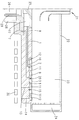
도 1은 기판 홀더(2)가 배치되어 있는 기판 홀더 지지체(1)를 평면도로 개략적으로 도시한 도면이고,
도 2는 제 1 변형 예의 기판 홀더 지지체(1)를 도 1의 라인 Ⅱ-Ⅱ을 따라 절단한 단면도이며,
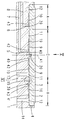
도 3은 제 2 변형 예의 도 2에 따른 도면이고,
도 4는 도 3의 커트 아우트 Ⅳ를 확대한 도면이며,
도 5는 도 4의 화살표 V에 따른 평면도이고,
도 6은 도 4의 커트 아우트 Ⅵ를 확대한 도면이며,
도 7은 가스 혼합 시스템을 개략적으로 도시한 도면이며,
도 8 내지 도 13은 도 5에 따른 베어링 포켓(4)의 바닥부(4')를 설계하기 위한 다양한 대안 예들이고,
도 14는 구역들(A 또는 C) 안으로의 상이한 열 전도성의 가스 혼합물들의 공급 작용에 대해 도시한 개략도이며,
도 15는 추가의 가스 혼합 시스템을 도시한 도면이다.Embodiments of the present invention are described below with reference to the accompanying drawings:
1 is a plan view schematically showing a
2 is a cross-sectional view of the
Figure 3 is a view according to Figure 2 of the second variant,
FIG. 4 is an enlarged view of the cutout IV of FIG. 3,
5 is a plan view according to arrow V in Fig. 4,
FIG. 6 is an enlarged view of the cutout VI of FIG. 4,
Figure 7 is a schematic illustration of a gas mixing system,
8 to 13 are various alternative examples for designing the bottom portion 4 'of the
14 is a schematic diagram illustrating the supply action of different thermal conductive gas mixtures into zones A or C,
15 is a diagram showing an additional gas mixing system.
CVD-반응기는 상세히 도시되어 있지 않고, 도 7에 오로지 표시만 되어 있는 가스 기밀 방식의, 특히 특수강으로 된 반응기 하우징(31)으로 이루어지며, 상기 반응기 하우징은 도 7에 따른 가스 혼합 시스템 및 도면에 도시되지 않은 진공 펌프와 연결되어 있다. 상기 반응기 하우징 내부에는 프로세스 챔버(23)가 위치하고 있으며, 상기 프로세스 챔버는 석영 또는 흑연으로 이루어질 수 있는 커버(22)로부터 상부로 제한된다. 프로세스 챔버(23)는 방사형 대칭 구조를 갖고 그리고 중앙에 가스 유입구(21)를 구비하고 있는데, 상기 가스 유입구를 통해서는 프로세스 가스들이 프로세스 챔버(23)로 유입될 수 있다. 가스 유입구(21)에는 가스 혼합 시스템의 프로세스 가스들이 공급되며, 상기 프로세스 가스들로는 TMGa, TMIn, TMAl, 아르신, 포스핀 또는 메탄이 사용될 수 있다. 추가로 상기 가스 유입구(21)를 통해서는 예를 들어 수소, 질소 또는 불활성 가스와 같은 캐리어 가스가 유입된다. 도면에 도시되지 않은 진공 장치에 의해서는, 프로세스 챔버(23) 내부의 전압력이 1 밀리바 내지 대기압 사이의 값으로 유지된다. 방사상 외부에서 프로세스 챔버는 가스 배출구(24)에 의해 둘러싸여 있고, 상기 가수 배출기를 통해서는 캐리어 가스들 또는 분리 생성물들이 뽑아 내진다. The CVD-reactor is not shown in detail, but consists of a
프로세스 챔버(23)의 바닥부는 위쪽을 향하는 기판 홀더 지지체(1)의 표면 또는 아래쪽을 향하는 기판 홀더들(2)의 표면들에 의해서 형성된다. 상기 기판 홀더들(2) 상에는 코팅될 기판들(3)이 놓인다. 프로세스 챔버(23) 바닥부의 중심부는 센터링 플레이트(25)에 의해서 형성되고, 도 2에 도시된 실시 예에서는 상기 센터링 플레이트의 하부에 분배 볼륨(27)이 존재한다. 기판 홀더 지지체(1)는 중앙 지지체(26)에 의해서 지지되며, 가스 유입 라인들(28 및 29) 역시 상기 중앙 지지체를 통과하여 뻗어 있다.The bottom of the
기판 홀더 지지체(1)의 하부면은 가열기(30)에 의해서 가열된다. 실시 예에서는 RF-가열기가 사용되며, 상기 RF-가열기는 흑연으로 이루어진 기판 홀더 지지체(1)에서 와전류를 발생시킴으로써 열을 발생한다.The lower surface of the
전술한 유입 라인들(28, 29)은 유입 라인들(7, 8)로 연장되는데, 상기 유입 라인들(7, 8)은 유입 개구들(6, 7)의 도움으로 기판 홀더 지지체(1)의 포켓(4)의 바닥면(4')으로 통한다. 유입 라인들(28, 29)은 외부 라인들(38)을 통해 가스 혼합 시스템에 연결되어 있다. 상기 라인들에 의해서는 개별 가스 혼합물들이 베어링 포켓(4) 안으로 수용될 수 있다. 실시 예에서 가스 혼합 시스템은 질소용 공급원(35), 수소용 공급원(36) 그리고 헬륨용 공급원(37)을 구비한다. 리버싱 밸브들(34, 35)에 의해서는 이러한 가스들이 각각 질량 조절기(32, 33) 위치로 전환될 수 있으며, 상기 질량 조절기에 의해서는, 상이한 위치에 있는 유입 개구들(6, 7)을 통해서 베어링 포켓 안으로 수용되는 가스 조성물이 각각 조절될 수 있다. 질량 조절기들(32, 33)에 의해서 혼합된 가스들은 열전도 특성이 굉장히 상이한 2개의 가스로 이루어지는데, 예를 들면 N2-H2, Ar-H2, N2-He, Ar-He의 가스 쌍들로 이루어진다. 가스 조성물 설정에 의해서는, 가스 혼합물의 열 전도성이 조정될 수 있다.The inflow lines 28 and 29 described above extend to the
베어링 포켓(4)의 바닥부(4')는 상이한 방식으로 구조화될 수 있다. 도 5 또는 도 8 내지 도 13은 이와 관련한 예들을 제시하고 있다.The bottom portion 4 'of the
모든 실시 예에서, 베어링 포켓(4)의 바닥부(4')는 2개의 동심 구역으로 분할된다. 내부 동심 구역(C)은 선택적인 센터링 핀(20)이 그 내부에 존재하는 중심부 중심으로 연장되며, 상기 센터링 핀은 기판 홀더(2)의 센터링 개구에 삽입된다. 중심부(41) 주위에는 제 1 공급 채널(40)이 배치되어 있고, 유입 라인(7)의 유입 개구(5)는 상기 공급 채널로 통한다. 폭이 좁은 연결 채널(42)을 통해서 상기 공급 채널(40)은 나선형 곡선으로 뻗은 가스 분배 채널(9)이 연결되어 있다. 가스 분배 채널(9)을 통과하여 흐르는 가스는 기판 홀더(2)를 갭 위치로 들어올릴 뿐만 아니라, 상기 기판 홀더(2)로 하여금 마찬가지로 중심부(41)를 중심으로 회전 운동하게 한다.In all embodiments, the bottom portion 4 'of the
구역(C)의 방사상 외부 영역에는 환상 선(circular line)으로 뻗은 가스 수집 채널(11)이 있고, 상기 가스 수집 채널은 배출 라인(13)에 연결되어 있다. 배출 라인(13)은 기판 홀더 지지체(1)를 횡단하는 지름 크기의 수직 보어이며, 유입 개구(5)를 거쳐 공급된 가스는 상기 수직 보어를 통해 다시 배출될 수 있다. In the radially outer region of the zone C there is a
중심 구역(C)과 외부 링 구역(A) 간 경계는 확산 장벽에 의해서 형성되며, 상기 확산 장벽의 구조는 도 6에 제시되어 있다. 링(15)은 베어링 포켓(4)의 바닥부(4')의 링 그루우브(16)에 삽입된다. 상기 링은 바닥부(4')로부터 외부로 돌출하여 기판 홀더 후면의 링 그루우브(17) 안으로 돌출된다. 링 그루우브(17)의 폭이 밀봉 링(15)의 폭보다 크며, 그 결과 약간의 밀봉 갭(18)이 발생하게 된다. 상기 밀봉 갭은 구역들(A와 C) 사이의 래버린스 시일 타입을 형성한다.The boundary between the central zone C and the outer ring zone A is formed by a diffusion barrier, and the structure of the diffusion barrier is shown in FIG. The
구역(A)의 방사상 내부 영역에서 베어링 포켓(4)의 바닥부(4')에서는 제 1 동심 링이 연장되며, 상기 제 1 동심 링은 공급 채널(39)을 형성하고 그리고 유입 개구(6)에 연결되어 있다. 연결 채널들(43)을 통해 공급 채널(39)은 마찬가지로 나선형 곡선들로 뻗은 가스 분배 채널들(10)에 연결되어 있다. 구역(A)의 방사상 외부 영역에는 지름 크기의 배출 라인(14)에 연결된 가스 수집 채널(12)이 있으며, 상기 배출 라인은 마찬가지로 지름 크기의 수직 보어이다. 배출 라인(14)에 의해서는 유입 개구(6)를 통해 반입된 가스가 누출될 수 있다.At the bottom 4 'of the
기판 홀더(2)의 높이는 대략 베어링 포켓(4)의 깊이에 상응하고, 상기 기판 홀더(2)는 프로세스 챔버(23) 쪽을 향하는 자체 표면상에 캐비티를 가지며, 상기 캐비티 내에는 기판(3)이 놓여 있다.The height of the
도 2에 도시된 실시 예에서 유입 라인(29)은 가스 분배 챔버(27)로 통하며, 방사상 외부 구역들로 통하는 모든 유입 라인들(8)은 상기 가스 분배 챔버로부터 가스가 공급되고 있다. 중심 구역(C)의 유입 라인들(28)에도 마찬가지로 공통으로 가스 혼합물이 공급될 수 있다.In the embodiment shown in FIG. 2, the
도 8에 도시된 실시 예의 경우에는 오로지 방사상 외부 구역(A)에만 나선형 채널들(10)이 존재한다. 도 9에 도시된 실시 예의 경우에는 내부 구역(C)과 외부 구역(A) 모두에 나선형 채널들(9, 10)이 존재한다.In the case of the embodiment shown in Fig. 8, there are only
도 10에 도시된 실시 예의 경우에는 방사상 외부 구역(A)에 폭이 넓은 나선형 채널들(10)이 존재한다.In the case of the embodiment shown in FIG. 10, there are wide
도 11에 도시된 실시 예에서는 방사상 외부 구역(A)이 나선형으로 뻗은 단 하나의 가스 채널(10)을 구비하고 있다. 도 12는 도 8과 마찬가지로 외부 구역(A)에 배치된 가스 채널들만을 도시한다. 도 13은 중심 구역(C)에만 복수의 가스 채널들(9)이 제공된 실시 예를 도시한다.In the embodiment shown in FIG. 11, the radially outer zone A has only one
전술한 장치의 기능은 다음과 같다:The functions of the above-described apparatus are as follows:
코팅 공정시 기판(3)의 가장자리들이 아치 모양으로 되거나 또는 기울어지게 됨으로써, 단지 기판의 중심부만 또는 단지 기판(3)의 가장자리만 기판 홀더(2)의 표면상에 평면으로 놓인다. 다른 경우에는 기판(3)과 기판 홀더(2) 사이에, 경우에 따라 국부적으로 상이한 갭 높이를 갖는 갭이 위치하게 된다. Only the center of the substrate or only the edge of the
기판(3)상에 증착된 층들의 품질 및 층 두께는 대부분 기판 표면 온도에 좌우된다. 바로 앞에서 언급한 기판 표면 온도는 국부적인 열 유입에 의해 좌우된다. 본 발명에 따르면, 국부적인 열 유입은 베어링 포켓(4)의 바닥부(4')와 기판 홀더(2)의 하부면 사이의 가스 갭의 열 전도성의 영향에 의해 조절된다. 유입 개구들(5, 6)을 통과하여 베어링 포켓(4) 안으로 유입되는 가스가 기판 홀더(2)를 갭 간격 위치로 들어올림으로써, 결과적으로 가스 쿠션(19)이 형성된다. 확산 장벽(15)으로 인해, 2개의 분리된 가스 쿠션(19)이 사용되며, 상기 가스 쿠션들은 유입 개구들(5, 6)을 통과하여 갭 중간 공간으로 유입되는 가스에 의해 개별적으로 설계된다. 개별 구역들(A, C)로 유입된 가스 혼합물들은 상이한 열 전도성을 갖는다. 예를 들어 중앙 구역(C)으로는 높은 열 전도성을 갖는 가스 혼합물이 주입되고, 외부 구역(A)으로는 낮은 전도성을 갖는 가스 혼합물이 주입되면, 기판 홀더(2)의 표면상에서, 도 14에 a로 개략적으로 도시된 바와 같은 온도 프로파일이 설정된다. 중앙 구역(C)으로 유입된 가스가 외부 구역(A)으로 유입된 가스보다 단지 약간 더 높은 전도성을 갖는 경우에는 도 14에 b로 표시된 온도 프로파일이 설정된다. The quality and layer thickness of the layers deposited on the
외부 구역(A)으로 유입되는 가스 혼합물이 중앙 구역(C)으로 유입되는 가스 혼합물보다 더 높은 열 전도성을 가짐으로써, 도 14에 c로 도시된 온도 프로파일이 설정된다. 이제 상기 예들(a 및 b)과는 달리 중앙 영역은 주변 영역보다 온도가 높지 않고, 오히려 외부 영역이 중앙 영역보다 더 높은 표면 온도를 갖는다. 중앙 영역과 외부 영역 간의 온도차는, 유입된 가스 혼합물들의 열 전도성 차가 커짐으로써 훨씬 더 증가될 수 있다. 다른 가스 쌍들의 사용에 의해서, 온도 프로파일 곡선들의 양적인(quantitative) 면뿐만 아니라 성질상(qualitative)의 면에도 영향을 줄 수 있는데, 이러한 사실은 예들 들어 d로 도시된 온도 프로파일이 보여준다.The temperature profile shown in FIG. 14C is set by having the thermal conductivity higher than that of the gas mixture flowing into the outer region A into the central region C. [ Unlike the above examples (a and b), the temperature of the central region is not higher than that of the peripheral region, and the outer region has a surface temperature higher than that of the central region. The temperature difference between the central region and the outer region can be increased even more by the increase in the thermal conductivity difference of the introduced gas mixtures. The use of different gas pairs can also affect the aspect of qualitative as well as quantitative aspects of the temperature profile curves, which shows, for example, the temperature profile shown as d.
도 15에 도시된 가스 혼합 시스템에서는 2개의 가스(35, 36), 즉 질소 및 수소가 준비된다. 개별 가스들은 유입 라인 및 리버싱 밸브들(34)을 통해서 질량 흐름 조절기들(32, 33)에 공급된다. 본 실시 예에는 3개의 기판 홀더가 제공되어 있으며, 상기 기판 홀더들에는 중앙 구역(10)에서 각각 분리된 상태로 가스들(35, 36)의 혼합물이 제공된다. 그에 상응하는 방식으로 가스 흐름들은 질량 흐름 조절기들(32, 33)에 의해 조절된다.In the gas mixing system shown in Fig. 15, two
외부 링 구역에는 유사한 방식으로 리버싱 밸브들(34') 및 질량 흐름 조절기들(32', 33')을 통해서 가스 혼합물이 제공된다. 본 실시 예의 경우, 내부 구역(C)으로 향하는 유입 라인과 외부 구역(A) 사이에는 압력 조절기(44)가 제공되어 있다. 이러한 압력 조절기로서는 차압 박스(differential pressure box)가 사용되며, 그 결과 상기 2개의 구역(A와 C)의 압력 차가 조절될 수 있다. 또한, 구역(A)에 대한 유입 라인 내 압력은 벤트-라인(vent line)에 연결된 유량 압력 조절기(45)에 의해 조절된다. The outer ring zone is provided with a gas mixture in a similar manner through reversing valves 34 'and mass flow controllers 32', 33 '. In the case of the present embodiment, a
공개된 모든 특징들은 (그 자체로) 본 발명에 중요하다. 따라서, 관련/첨부된 우선권 서류(예비 출원서의 사본)의 특징들을 본 출원서의 청구범위에 수용하기 위해서도 상기 우선권 서류의 공개 내용은 전체 내용상으로 본 공개 출원서에 포함된다. 특히 종속항들을 기초로 한 부분 출원을 수행하기 위해, 상기 종속항들의 임의의 병렬 텍스트는 종래 기술의 독자적인 발명적 개선 예를 특징으로 한다.All the features disclosed are (by themselves) important to the present invention. Therefore, in order to accommodate the features of the related / attached priority document (copy of the preliminary application) in the claims of the present application, the disclosure content of the priority document is included in the present application in its entirety. In particular, in order to carry out a partial application based on dependent terms, any parallel text of the dependent claims is characterized by a unique inventive improvement of the prior art.
1: 기판 홀더 지지체 2: 기판 홀더
3: 기판 4: 베어링 포켓
4': 베어링 면 5: 유입 개구
6: 유입 개구 7: 유입 라인
8: 유입 라인 9: 가스 분배 채널
10: 가스 분배 채널 11: 가스 수집 채널
12: 가스 수집 채널 13: 배출 라인
14: 배출 라인 15: 밀봉 링(확산 장벽)
16: 링 그루우브 17: 링 그루우브
18: 갭 19: 가스 쿠션
20: 센터링 핀 21: 가스 유입구
22: 커버 23: 프로세스 챔버
24: 가스 배출구 25: 센터링 플레이트
26: 지지체 27: 분배 챔버
28: 유입 라인 29: 유입 라인
30: 가열기 31: 반응기 하우징
32: 질량 흐름 조절기 32': 질량 흐름 조절기
33: 질량 흐름 조절기 33': 질량 흐름 조절기
34: 리버싱 밸브 34': 리버싱 밸브
35: 가스 공급원 36: 가스 공급원
37: 가스 공급원 38: 라인들
39: 공급 채널 40: 회전축
41: 연결 채널 42: 연결 채널
43: 연결 채널 44: 압력 조절기
45: 압력 조절기
A: 외부 동심 구역
C: 내부 링 구역
a: 온도 프로파일
b: 온도 프로파일
c: 온도 프로파일1: substrate holder support 2: substrate holder
3: substrate 4: bearing pocket
4 ': Bearing surface 5: Inflow opening
6: inlet opening 7: inlet line
8: inlet line 9: gas distribution channel
10: gas distribution channel 11: gas collection channel
12: gas collecting channel 13: exhaust line
14: exhaust line 15: seal ring (diffusion barrier)
16: ring grooves 17: ring grooves
18: gap 19: gas cushion
20: centering pin 21: gas inlet
22: Cover 23: Process chamber
24: gas outlet 25: centering plate
26: support 27: dispensing chamber
28: inflow line 29: inflow line
30: heater 31: reactor housing
32: Mass flow regulator 32 ': Mass flow regulator
33: mass flow regulator 33 ': mass flow regulator
34: reversing valve 34 ': reversing valve
35: gas supply source 36: gas supply source
37: gas supply source 38: lines
39: supply channel 40:
41: connection channel 42: connection channel
43: connection channel 44: pressure regulator
45: Pressure regulator
A: External concentric zone
C: Inner ring section
a: Temperature profile
b: Temperature profile
c: Temperature profile
Claims (11)
복수의 가스 유입 라인(7, 8)들은 상기 베어링 면(4')으로 통하고, 상기 가스 유입 라인(7, 8)들을 통해 베어링 면(4')과 후면 사이에 있는 공간으로 보내어진 가스들은 상기 기판 홀더(2)를 지지하는 가스 쿠션(19)을 형성하며,
상기 가스 쿠션은 각각 할당된 가스 유입 라인(7, 8)을 통해 개별적으로 공급될 수 있는 복수의 구역(A, C)들을 포함하고, 상기 구역(A, C)들은 상기 구역(A, C)들 간의 가스 교환을 저지하는 수단(15)들에 의해 서로 분리되어 있으며, 하나 이상의 내부의 구역(C)에는 가스 배출 라인(13)이 할당되어 있고, 상기 가스 배출 라인을 통해서 상기 가스 유입 라인(7)을 거쳐 상기 내부의 구역(C)으로 공급된 가스가 배출될 수 있는 것을 특징으로 하는,
CVD-반응기.A process chamber 23, a substrate holder support 1 disposed within the process chamber and including one or more bearing surfaces 4 ', and a back side of the substrate holder 2 facing the bearing surface 4' (2), comprising:
A plurality of gas inlet lines 7,8 communicate with the bearing surface 4'and the gases sent through the gas inlet lines 7,8 to the space between the bearing surface 4 ' A gas cushion 19 for supporting the substrate holder 2 is formed,
The gas cushion comprises a plurality of zones A and C which can be fed individually via respective assigned gas inlet lines 7 and 8 and wherein the zones A and C are connected to the zones A and C, Are separated from one another by means (15) for preventing gas exchange between the gas inlet line (C) and the gas inlet line (C) Characterized in that the gas supplied to the internal zone (C)
CVD-reactor.
상기 구역(A, C)들 간의 가스 교환을 저지하는 수단(15)들이 상기 기판 홀더(2)의 회전 중심부를 둘러싸는 링 모양의 확산 장벽(15)을 형성하는 것을 특징으로 하는,
CVD-반응기.The method according to claim 1,
Characterized in that means (15) for preventing gas exchange between the zones (A, C) form a ring-shaped diffusion barrier (15) surrounding the rotational center of the substrate holder (2)
CVD-reactor.
상기 확산 장벽(15)은 표면보다 더 돌출하는 링(15)이며, 상기 링은 상기 2개의 구역(A, C)들의 가스 쿠션들 사이에서 다중 편향된 갭(18)만 유지되는 방식으로 마주 놓인 면에 배치된 링 그루우브(17)에 삽입되는 것을 특징으로 하는,
CVD-반응기. 3. The method of claim 2,
The diffusion barrier 15 is a ring 15 projecting more than the surface and the ring is located between the gas cushions of the two zones A and C in such a way that only a multi- Is inserted into a ring groove (17) disposed in the ring groove (17)
CVD-reactor.
상기 하나 이상의 내부의 구역(C)에 각각 하나의 가스 배출 라인(13)이 할당된 것을 특징으로 하는,
CVD-반응기.4. The method according to any one of claims 1 to 3,
Characterized in that said one or more internal zones (C) are each assigned one gas discharge line (13)
CVD-reactor.
상기 가스 배출 라인(13, 14)이 방사상 외부 가스 수집 채널(11, 12)과 연결되고, 상기 가스 수집 채널이 상기 구역(A, C)들의 가장자리를 따라 원주 방향으로 연장되는 것을 특징으로 하는,
CVD-반응기. 4. The method according to any one of claims 1 to 3,
Characterized in that the gas discharge lines (13,14) are connected with the radially outer gas collection channels (11,12) and the gas collection channels extend in the circumferential direction along the edges of the zones (A) and (C)
CVD-reactor.
상기 유입 라인(7)이 공급 채널(39, 40)과 연결되고, 상기 공급 채널이 방사상 내부에 놓이는 방식으로 상기 구역(A, C)들의 원주 가장자리를 따라 연장되는 것을 특징으로 하는,
CVD-반응기.4. The method according to any one of claims 1 to 3,
Characterized in that said inflow line (7) is connected with feed channels (39, 40) and extends along the circumferential edges of said zones (A, C)
CVD-reactor.
상기 기판 홀더(2)가 상기 기판 홀더 지지체(1)의 포켓(4) 내에 삽입되어 있고, 상기 포켓(4)의 포켓 바닥부가 상기 베어링 면(4')을 형성하며, 상기 기판 홀더(2)의 후면은 상기 베어링 면(4')에 대해 평행하게 뻗으며, 프로세스 챔버(23)의 커버(22) 방향으로 상부로 향하는 상기 기판 홀더의 측면에 기판(3)이 배치되어 있고, 상기 포켓 바닥부는 공급 채널(39, 40) 및 상기 공급 채널과 연결되는 가스 분배 채널(9, 10)을 포함하며, 상기 가스 분배 채널(9, 10)은 배출 라인(13, 14)과 연결되는 가스 수집 채널(11, 12)에 의해서 둘러싸인 것을 특징으로 하는,
CVD-반응기.4. The method according to any one of claims 1 to 3,
Wherein the substrate holder 2 is inserted into the pocket 4 of the substrate holder support 1 and the pocket bottom of the pocket 4 forms the bearing surface 4 ' (3) is disposed on the side of the substrate holder which faces upwardly in the direction of the cover (22) of the process chamber (23), the rear surface of which extends parallel to the bearing surface (4 ' The gas distribution channel (9, 10) comprises a gas collection channel (9, 10) connected to a discharge line (13, 14) (11, 12). ≪ RTI ID = 0.0 >
CVD-reactor.
상기 기판 홀더 지지체(1)의 중심부 주위로 원형 배열로 배치된 다수의 베어링 포켓(4)을 구비하고, 상기 베어링 포켓들이 각각 하나의 기판 홀더(2)를 수용하며, 상기 기판 홀더가 각각 복수의 구역(A, C)들을 갖는 가스 쿠션(19)에 의해 지지되고, 가스 공급 장치에 개별적으로 연결되거나 또는 1개의 공통 가스 공급 장치에 연결된, 개별 구역(A, C)들을 위한 유입 라인(7, 8)들이 제공되어 있는 특징으로 하는,
CVD-반응기.4. The method according to any one of claims 1 to 3,
A plurality of bearing pockets (4) arranged in a circular array around a central portion of the substrate holder support (1), the bearing pockets each receiving one substrate holder (2), each of the substrate holders Are provided with inflow lines 7, 7 for the individual zones A, C, which are supported by gas cushions 19 having zones A, C and which are connected individually to the gas supply or connected to one common gas supply, 8) are provided,
CVD-reactor.
상기 동적 가스 쿠션(19)이 서로 동축으로 배치된 복수의 구역(A, C)들을 포함하고, 상기 구역들로는 가스(35, 36, 37)들 또는 서로 상이한 열 전도성을 갖는 가스 혼합물들이 공급되고, 상기 구역(A, C)들은 상기 구역(A, C)들 간의 가스 교환을 저지하는 수단(15)들에 의해 서로 분리되어 있는 것을 특징으로 하는,
기판 홀더의 표면 온도 제어 방법.A method for controlling a surface temperature of a substrate holder (2) supported on a dynamic gas cushion (19) and heated from below,
The dynamic gas cushion (19) comprises a plurality of zones (A, C) coaxially arranged with one another, wherein the zones (35, 36, 37) or gas mixtures having different thermal conductivities are supplied, Characterized in that the zones A and C are separated from each other by means 15 for preventing gas exchange between the zones A and C. [
Method of controlling surface temperature of a substrate holder.
상기 기판 홀더 지지체는 상기 프로세스 챔버(23)를 향하는 자체 측면 상에서 베어링 면(4') 위에서 기판 홀더(2)를 지지하고 자체 후면에서부터 가열기(30)에 의해 가열될 수 있으며, 가스 유입 라인(7, 8)들은 상기 베어링 면(4')으로 통하고, 상기 가스 유입 라인들에는 가스 혼합 시스템으로부터 가스들이 공급되며, 상기 가스들은 상기 기판 홀더(2)를 지지하는 동적 가스 쿠션(19)을 형성하며,
상기 동적 가스 쿠션(19)이 인접한 복수의 구역(A, C)들을 포함하고, 상기 구역(A, C)들에는 개별 가스 유입 라인(7, 8)들을 통해 상기 가스 혼합 시스템으로부터 가스가 공급되며, 상기 구역(A, C)들은 구역(A, C)들 간의 가스 교환을 저지하는 수단(15)들에 의해 서로 분리되어 있고, 상기 가스 혼합 시스템이 가스 흐름 조절 부재(32, 33, 34, 35)들을 구비하고, 상기 가스 흐름 조절 부재들에 의해 서로 상이한 가스들 또는 개별 가스 유입 라인(7, 8)들을 위한 가스 혼합물들이 준비될 수 있는 것을 특징으로 하는,
기판 처리 장치.An apparatus for processing substrates with a CVD-reactor having a process chamber (23) and a substrate holder support (1) disposed in the process chamber,
The substrate holder support supports the substrate holder 2 on the bearing surface 4 'on its side facing the process chamber 23 and can be heated by the heater 30 from its rear side, and the gas inlet line 7 , 8) pass through the bearing surface (4 '), and the gas inlet lines are supplied with gases from a gas mixing system, which form a dynamic gas cushion (19) supporting the substrate holder In addition,
The dynamic gas cushion 19 comprises a plurality of adjoining zones A and C which are supplied with gas from the gas mixing system via individual gas inlet lines 7 and 8 , Said zones A and C being separated from each other by means 15 for preventing gas exchange between zones A and C and said gas mixing system comprising gas flow control members 32, 35), characterized in that gas mixtures for the gases different from one another or the individual gas inlet lines (7, 8) can be prepared by the gas flow control members
/ RTI >
상기 가스 혼합 시스템이 제 1 가스를 위한 제 1 가스 공급원(35) 및 제 2 가스를 위한 제 2 가스 공급원(36)을 가지며, 가스 조성물 조절에 의해 각각의 구역(A, C) 내에서 상기 가스 쿠션의 열 전도성을 개별적으로 설정하기 위해, 서로 다른 열 전도성을 갖는 2개의 가스들이 상기 가스 흐름 조절 부재(32, 33, 34)들에 의해 개별적으로 혼합될 수 있는 것을 특징으로 하는,
기판 처리 장치.11. The method of claim 10,
Characterized in that the gas mixing system has a first gas supply source (35) for the first gas and a second gas supply source (36) for the second gas, Characterized in that two gases with different thermal conductivities can be mixed individually by said gas flow regulating members (32, 33, 34) to individually set the thermal conductivity of the cushion.
/ RTI >
Applications Claiming Priority (3)
| Application Number | Priority Date | Filing Date | Title |
|---|---|---|---|
| DE102009044276A DE102009044276A1 (en) | 2009-10-16 | 2009-10-16 | CVD reactor with multi-zone gas cushion substrate holder |
| DE102009044276.6 | 2009-10-16 | ||
| PCT/EP2010/065105 WO2011045241A1 (en) | 2009-10-16 | 2010-10-08 | Cvd reactor having a substrate holder resting on a gas cushion comprising a plurality of zones |
Publications (2)
| Publication Number | Publication Date |
|---|---|
| KR20120083470A KR20120083470A (en) | 2012-07-25 |
| KR101770577B1 true KR101770577B1 (en) | 2017-08-23 |
Family
ID=43064427
Family Applications (1)
| Application Number | Title | Priority Date | Filing Date |
|---|---|---|---|
| KR1020127012630A Active KR101770577B1 (en) | 2009-10-16 | 2010-10-08 | Cvd reactor having a substrate holder resting on a gas cushion comprising a plurality of zones |
Country Status (8)
| Country | Link |
|---|---|
| US (1) | US9447500B2 (en) |
| EP (1) | EP2488679B1 (en) |
| JP (1) | JP5732466B2 (en) |
| KR (1) | KR101770577B1 (en) |
| CN (1) | CN102656294B (en) |
| DE (1) | DE102009044276A1 (en) |
| TW (1) | TWI523974B (en) |
| WO (1) | WO2011045241A1 (en) |
Families Citing this family (41)
| Publication number | Priority date | Publication date | Assignee | Title |
|---|---|---|---|---|
| JP5409413B2 (en) * | 2010-01-26 | 2014-02-05 | 日本パイオニクス株式会社 | III-nitride semiconductor vapor phase growth system |
| KR20110136583A (en) * | 2010-06-15 | 2011-12-21 | 삼성엘이디 주식회사 | Susceptor and chemical vapor deposition apparatus having the same |
| DE102011055061A1 (en) * | 2011-11-04 | 2013-05-08 | Aixtron Se | CVD reactor or substrate holder for a CVD reactor |
| DE102012101923B4 (en) * | 2012-03-07 | 2019-11-07 | Osram Opto Semiconductors Gmbh | Substrate carrier assembly, coating system with substrate carrier assembly and method for performing a coating method |
| TWI506163B (en) * | 2012-07-13 | 2015-11-01 | Epistar Corp | Reactive apparatus for vapor deposition and carrier thereof |
| DE102012108986A1 (en) | 2012-09-24 | 2014-03-27 | Aixtron Se | Substrate holder for use in process chamber of semiconductor substrate treatment device, has recess having bearing surfaces which lie in common plane, and wall in region of projections in plan view of top face is straight |
| DE102014104218A1 (en) * | 2014-03-26 | 2015-10-01 | Aixtron Se | CVD reactor with feed-zone temperature control |
| KR102372893B1 (en) | 2014-12-04 | 2022-03-10 | 삼성전자주식회사 | Chemical vapor deposition apparatus for fabricating light emitting diode(LED) |
| CN104835763B (en) * | 2015-04-27 | 2018-08-14 | 沈阳拓荆科技有限公司 | A kind of controllable temperature heating dish of petal surface texture |
| US9738975B2 (en) * | 2015-05-12 | 2017-08-22 | Lam Research Corporation | Substrate pedestal module including backside gas delivery tube and method of making |
| CN105047543A (en) * | 2015-06-17 | 2015-11-11 | 沈阳拓荆科技有限公司 | Controllable temperature heating disc of spiral-type surface structure |
| CN106684029B (en) * | 2015-11-10 | 2021-01-08 | 北京北方华创微电子装备有限公司 | Bearing device and semiconductor processing equipment |
| CN105547322B (en) * | 2016-01-07 | 2018-05-11 | 交通运输部公路科学研究所 | A kind of method that VMT Vehicle-Miles of Travel calculating is carried out using satellite location data |
| DE102016110788A1 (en) * | 2016-06-13 | 2017-12-14 | Aixtron Se | Apparatus and method for the production of optoelectronic components, in particular of multi-junction solar cells in a continuous process |
| US20190390336A1 (en) * | 2017-01-27 | 2019-12-26 | Aixtron Se | Transport ring |
| DE102017105947A1 (en) * | 2017-03-20 | 2018-09-20 | Aixtron Se | Susceptor for a CVD reactor |
| KR102369676B1 (en) | 2017-04-10 | 2022-03-04 | 삼성디스플레이 주식회사 | Apparatus and method for manufacturing a display apparatus |
| JP7321768B2 (en) * | 2018-05-23 | 2023-08-07 | 信越化学工業株式会社 | Chemical vapor deposition apparatus and film forming method |
| DE102018123281A1 (en) * | 2018-09-21 | 2020-03-26 | Aixtron Se | CVD reactor with substrate holders rotatably mounted on a gas cushion |
| DE102018124957A1 (en) * | 2018-10-10 | 2020-04-16 | Aixtron Se | CVD reactor with substrate holders resting on gas cushions |
| DE102018131751A1 (en) * | 2018-12-11 | 2020-06-18 | Aixtron Se | Susceptor of a CVD reactor |
| DE102018132673A1 (en) | 2018-12-18 | 2020-06-18 | Aixtron Se | Susceptor for a CVD reactor |
| CN109594063A (en) * | 2018-12-27 | 2019-04-09 | 西安奕斯伟硅片技术有限公司 | A kind of epitaxial reaction equipment |
| DE102019104433A1 (en) | 2019-02-21 | 2020-08-27 | Aixtron Se | CVD reactor with means for locally influencing the susceptor temperature |
| CN110172683A (en) * | 2019-06-27 | 2019-08-27 | 云谷(固安)科技有限公司 | Heating mechanism, plasma chamber and the method to form a film on substrate |
| KR102238016B1 (en) * | 2019-11-07 | 2021-04-08 | 주식회사 한화 | Apparatus for processing substrate |
| DE102020105753A1 (en) | 2020-03-04 | 2021-09-09 | Aixtron Se | A substrate holder for a CVD reactor provided with a large number of structural elements on an underside |
| DE102020107517A1 (en) | 2020-03-18 | 2021-09-23 | Aixtron Se | Susceptor for a CVD reactor |
| TWI729778B (en) * | 2020-04-21 | 2021-06-01 | 錼創顯示科技股份有限公司 | Tray structure |
| DE102020127662A1 (en) | 2020-10-21 | 2022-04-21 | Aixtron Se | Susceptor for a CVD reactor |
| CN114908334B (en) * | 2021-02-09 | 2025-10-14 | 中微半导体设备(上海)股份有限公司 | Lower electrode assembly, chemical vapor deposition device and substrate temperature control method |
| CN115029774B (en) * | 2022-06-20 | 2024-11-26 | 北京北方华创微电子装备有限公司 | Semiconductor process equipment and its carrier |
| CN118854257B (en) * | 2023-04-28 | 2026-02-06 | 北京北方华创微电子装备有限公司 | Semiconductor processing equipment |
| DE102024126450A1 (en) | 2024-09-13 | 2026-03-19 | Aixtron Se | CVD reactor |
| DE102024126451A1 (en) | 2024-09-13 | 2026-03-19 | Aixtron Se | CVD reactor |
| DE102024126443A1 (en) | 2024-09-13 | 2026-03-19 | Aixtron Se | CVD reactor |
| WO2026057801A2 (en) | 2024-09-13 | 2026-03-19 | Aixtron Se | Cvd reactor |
| DE102024126445A1 (en) | 2024-09-13 | 2026-03-19 | Aixtron Se | CVD reactor |
| DE102024126444A1 (en) | 2024-09-13 | 2026-03-19 | Aixtron Se | CVD reactor |
| DE102024126448A1 (en) | 2024-09-13 | 2026-03-19 | Aixtron Se | CVD reactor |
| DE102024126446A1 (en) | 2024-09-13 | 2026-03-19 | Aixtron Se | CVD reactor |
Citations (4)
| Publication number | Priority date | Publication date | Assignee | Title |
|---|---|---|---|---|
| US4860687A (en) | 1986-03-21 | 1989-08-29 | U.S. Philips Corporation | Device comprising a flat susceptor rotating parallel to a reference surface about a shift perpendicular to this surface |
| US5033538A (en) | 1989-05-08 | 1991-07-23 | Balzers Aktiengesellschaft | Workpiece carrier for a disk-shaped workpiece as well as a vacuum process space |
| US5177878A (en) | 1989-05-08 | 1993-01-12 | U.S. Philips Corporation | Apparatus and method for treating flat substrate under reduced pressure in the manufacture of electronic devices |
| US20080227227A1 (en) | 2007-03-12 | 2008-09-18 | Tokyo Electron Limited | Dynamic temperature backside gas control for improved within-substrate process uniformity |
Family Cites Families (17)
| Publication number | Priority date | Publication date | Assignee | Title |
|---|---|---|---|---|
| JPH03135014A (en) * | 1989-10-20 | 1991-06-10 | Furukawa Electric Co Ltd:The | Film formation apparatus for wafer |
| JPH07335630A (en) * | 1994-06-13 | 1995-12-22 | Hitachi Ltd | Vacuum processing device |
| US5468299A (en) * | 1995-01-09 | 1995-11-21 | Tsai; Charles S. | Device comprising a flat susceptor rotating parallel to a reference surface about a shaft perpendicular to this surface |
| US6053982A (en) * | 1995-09-01 | 2000-04-25 | Asm America, Inc. | Wafer support system |
| US6170428B1 (en) * | 1996-07-15 | 2001-01-09 | Applied Materials, Inc. | Symmetric tunable inductively coupled HDP-CVD reactor |
| US6040011A (en) * | 1998-06-24 | 2000-03-21 | Applied Materials, Inc. | Substrate support member with a purge gas channel and pumping system |
| DE10056029A1 (en) * | 2000-11-11 | 2002-05-16 | Aixtron Ag | Controlling surface temperature of substrates supported by carriers on dynamic gas cushions in process chamber of CVD reactor comprises varying gas stream producing gas cushions from average value of optically measured surface temperatures |
| JP2002280373A (en) * | 2001-03-19 | 2002-09-27 | Hitachi Kokusai Electric Inc | Substrate processing equipment |
| DE10133914A1 (en) * | 2001-07-12 | 2003-01-23 | Aixtron Ag | Apparatus to deposit crystalline layers on semiconductor wafers comprises rotating wafer holders mounted on rotating mounting forming floor of process chamber whose roof contains central gas inlet |
| US6853953B2 (en) * | 2001-08-07 | 2005-02-08 | Tokyo Electron Limited | Method for characterizing the performance of an electrostatic chuck |
| US6797069B2 (en) * | 2002-04-08 | 2004-09-28 | Cree, Inc. | Gas driven planetary rotation apparatus and methods for forming silicon carbide layers |
| JP2004014952A (en) * | 2002-06-10 | 2004-01-15 | Tokyo Electron Ltd | Processing device and processing method |
| US7156951B1 (en) | 2002-06-21 | 2007-01-02 | Lam Research Corporation | Multiple zone gas distribution apparatus for thermal control of semiconductor wafer |
| DE102006018514A1 (en) * | 2006-04-21 | 2007-10-25 | Aixtron Ag | Apparatus and method for controlling the surface temperature of a substrate in a process chamber |
| US8440049B2 (en) * | 2006-05-03 | 2013-05-14 | Applied Materials, Inc. | Apparatus for etching high aspect ratio features |
| DE102007026348A1 (en) * | 2007-06-06 | 2008-12-11 | Aixtron Ag | Method and device for temperature control of the surface temperatures of substrates in a CVD reactor |
| KR101405346B1 (en) * | 2008-01-04 | 2014-06-12 | 삼성디스플레이 주식회사 | Substrate pedestal, apparatus for treating substrate having it and the method for aligning substrate |
-
2009
- 2009-10-16 DE DE102009044276A patent/DE102009044276A1/en not_active Withdrawn
-
2010
- 2010-10-08 CN CN201080057579.5A patent/CN102656294B/en active Active
- 2010-10-08 EP EP10763696.1A patent/EP2488679B1/en active Active
- 2010-10-08 WO PCT/EP2010/065105 patent/WO2011045241A1/en not_active Ceased
- 2010-10-08 US US13/502,356 patent/US9447500B2/en active Active
- 2010-10-08 JP JP2012533582A patent/JP5732466B2/en not_active Expired - Fee Related
- 2010-10-08 KR KR1020127012630A patent/KR101770577B1/en active Active
- 2010-10-11 TW TW099134552A patent/TWI523974B/en active
Patent Citations (4)
| Publication number | Priority date | Publication date | Assignee | Title |
|---|---|---|---|---|
| US4860687A (en) | 1986-03-21 | 1989-08-29 | U.S. Philips Corporation | Device comprising a flat susceptor rotating parallel to a reference surface about a shift perpendicular to this surface |
| US5033538A (en) | 1989-05-08 | 1991-07-23 | Balzers Aktiengesellschaft | Workpiece carrier for a disk-shaped workpiece as well as a vacuum process space |
| US5177878A (en) | 1989-05-08 | 1993-01-12 | U.S. Philips Corporation | Apparatus and method for treating flat substrate under reduced pressure in the manufacture of electronic devices |
| US20080227227A1 (en) | 2007-03-12 | 2008-09-18 | Tokyo Electron Limited | Dynamic temperature backside gas control for improved within-substrate process uniformity |
Also Published As
| Publication number | Publication date |
|---|---|
| JP5732466B2 (en) | 2015-06-10 |
| US20120204796A1 (en) | 2012-08-16 |
| CN102656294A (en) | 2012-09-05 |
| EP2488679B1 (en) | 2014-11-26 |
| TWI523974B (en) | 2016-03-01 |
| US9447500B2 (en) | 2016-09-20 |
| EP2488679A1 (en) | 2012-08-22 |
| CN102656294B (en) | 2014-06-11 |
| JP2013507779A (en) | 2013-03-04 |
| TW201124556A (en) | 2011-07-16 |
| WO2011045241A1 (en) | 2011-04-21 |
| KR20120083470A (en) | 2012-07-25 |
| DE102009044276A1 (en) | 2011-05-05 |
Similar Documents
| Publication | Publication Date | Title |
|---|---|---|
| KR101770577B1 (en) | Cvd reactor having a substrate holder resting on a gas cushion comprising a plurality of zones | |
| US8628616B2 (en) | Vapor-phase process apparatus, vapor-phase process method, and substrate | |
| US8841221B2 (en) | MOCVD reactor having cylindrical gas inlet element | |
| JP5358427B2 (en) | Apparatus and method for controlling substrate surface temperature in process chamber | |
| US7699934B2 (en) | Epitaxial wafer production apparatus and susceptor structure | |
| US8308867B2 (en) | Device for the temperature control of the surface temperatures of substrates in a CVD reactor | |
| JP5619164B2 (en) | CVD method and CVD reactor | |
| US20070186853A1 (en) | System and method for varying wafer surface temperature via wafer-carrier temperature offset | |
| JP7682263B2 (en) | CVD reactor with temperature adjustable gas inlet region - Patents.com | |
| KR101443702B1 (en) | Film forming apparatus and film forming method | |
| TW202434757A (en) | Method and apparatus for depositing a SiC layer on a substrate | |
| KR20130030745A (en) | Atomic layer deposition chamber with multi inject | |
| CN115298351B (en) | Susceptor for CVD reactor | |
| TW202236477A (en) | CVD reactor having a process chamber floor rising in a feeder zone | |
| US20240337020A1 (en) | Gas injector for epitaxy and cvd chamber | |
| TW202035779A (en) | Susceptor of a CVD reactor | |
| JP2024510364A (en) | Gas injector for epitaxy chamber and CVD chamber | |
| KR20210017147A (en) | Apparatus for supplying gas and apparatus for processing substrate using the same | |
| TW202140845A (en) | CVD reactor with dual pre-zone plates | |
| KR20250133691A (en) | Substrate processing device and method | |
| KR20250121017A (en) | Method and device for depositing SiC layers on a substrate | |
| TW202538086A (en) | Method and apparatus for depositing n-doped SiC | |
| TW202432886A (en) | Device for depositing a SiC layer on a substrate with an adjustable exhaust element |
Legal Events
| Date | Code | Title | Description |
|---|---|---|---|
| PA0105 | International application |
St.27 status event code: A-0-1-A10-A15-nap-PA0105 |
|
| PG1501 | Laying open of application |
St.27 status event code: A-1-1-Q10-Q12-nap-PG1501 |
|
| R17-X000 | Change to representative recorded |
St.27 status event code: A-3-3-R10-R17-oth-X000 |
|
| R18-X000 | Changes to party contact information recorded |
St.27 status event code: A-3-3-R10-R18-oth-X000 |
|
| A201 | Request for examination | ||
| PA0201 | Request for examination |
St.27 status event code: A-1-2-D10-D11-exm-PA0201 |
|
| P22-X000 | Classification modified |
St.27 status event code: A-2-2-P10-P22-nap-X000 |
|
| P22-X000 | Classification modified |
St.27 status event code: A-2-2-P10-P22-nap-X000 |
|
| E902 | Notification of reason for refusal | ||
| PE0902 | Notice of grounds for rejection |
St.27 status event code: A-1-2-D10-D21-exm-PE0902 |
|
| P11-X000 | Amendment of application requested |
St.27 status event code: A-2-2-P10-P11-nap-X000 |
|
| P13-X000 | Application amended |
St.27 status event code: A-2-2-P10-P13-nap-X000 |
|
| E902 | Notification of reason for refusal | ||
| PE0902 | Notice of grounds for rejection |
St.27 status event code: A-1-2-D10-D21-exm-PE0902 |
|
| T11-X000 | Administrative time limit extension requested |
St.27 status event code: U-3-3-T10-T11-oth-X000 |
|
| P11-X000 | Amendment of application requested |
St.27 status event code: A-2-2-P10-P11-nap-X000 |
|
| P13-X000 | Application amended |
St.27 status event code: A-2-2-P10-P13-nap-X000 |
|
| E701 | Decision to grant or registration of patent right | ||
| PE0701 | Decision of registration |
St.27 status event code: A-1-2-D10-D22-exm-PE0701 |
|
| GRNT | Written decision to grant | ||
| PR0701 | Registration of establishment |
St.27 status event code: A-2-4-F10-F11-exm-PR0701 |
|
| PR1002 | Payment of registration fee |
St.27 status event code: A-2-2-U10-U12-oth-PR1002 Fee payment year number: 1 |
|
| PG1601 | Publication of registration |
St.27 status event code: A-4-4-Q10-Q13-nap-PG1601 |
|
| PR1001 | Payment of annual fee |
St.27 status event code: A-4-4-U10-U11-oth-PR1001 Fee payment year number: 4 |
|
| PR1001 | Payment of annual fee |
St.27 status event code: A-4-4-U10-U11-oth-PR1001 Fee payment year number: 5 |
|
| PR1001 | Payment of annual fee |
St.27 status event code: A-4-4-U10-U11-oth-PR1001 Fee payment year number: 6 |
|
| PR1001 | Payment of annual fee |
St.27 status event code: A-4-4-U10-U11-oth-PR1001 Fee payment year number: 7 |
|
| P22-X000 | Classification modified |
St.27 status event code: A-4-4-P10-P22-nap-X000 |
|
| PR1001 | Payment of annual fee |
St.27 status event code: A-4-4-U10-U11-oth-PR1001 Fee payment year number: 8 |
|
| PR1001 | Payment of annual fee |
St.27 status event code: A-4-4-U10-U11-oth-PR1001 Fee payment year number: 9 |
|
| U11 | Full renewal or maintenance fee paid |
Free format text: ST27 STATUS EVENT CODE: A-4-4-U10-U11-OTH-PR1001 (AS PROVIDED BY THE NATIONAL OFFICE) Year of fee payment: 9 |
|
| P22-X000 | Classification modified |
St.27 status event code: A-4-4-P10-P22-nap-X000 |