KR101749956B1 - Computer keyboard with integrated an electrode arrangement - Google Patents
Computer keyboard with integrated an electrode arrangement Download PDFInfo
- Publication number
- KR101749956B1 KR101749956B1 KR1020127021392A KR20127021392A KR101749956B1 KR 101749956 B1 KR101749956 B1 KR 101749956B1 KR 1020127021392 A KR1020127021392 A KR 1020127021392A KR 20127021392 A KR20127021392 A KR 20127021392A KR 101749956 B1 KR101749956 B1 KR 101749956B1
- Authority
- KR
- South Korea
- Prior art keywords
- keyboard
- electrode
- hand
- electrodes
- keys
- Prior art date
- Legal status (The legal status is an assumption and is not a legal conclusion. Google has not performed a legal analysis and makes no representation as to the accuracy of the status listed.)
- Active
Links
Images


Classifications
-
- G—PHYSICS
- G06—COMPUTING OR CALCULATING; COUNTING
- G06F—ELECTRIC DIGITAL DATA PROCESSING
- G06F3/00—Input arrangements for transferring data to be processed into a form capable of being handled by the computer; Output arrangements for transferring data from processing unit to output unit, e.g. interface arrangements
- G06F3/01—Input arrangements or combined input and output arrangements for interaction between user and computer
- G06F3/048—Interaction techniques based on graphical user interfaces [GUI]
- G06F3/0487—Interaction techniques based on graphical user interfaces [GUI] using specific features provided by the input device, e.g. functions controlled by the rotation of a mouse with dual sensing arrangements, or of the nature of the input device, e.g. tap gestures based on pressure sensed by a digitiser
- G06F3/0488—Interaction techniques based on graphical user interfaces [GUI] using specific features provided by the input device, e.g. functions controlled by the rotation of a mouse with dual sensing arrangements, or of the nature of the input device, e.g. tap gestures based on pressure sensed by a digitiser using a touch-screen or digitiser, e.g. input of commands through traced gestures
- G06F3/04883—Interaction techniques based on graphical user interfaces [GUI] using specific features provided by the input device, e.g. functions controlled by the rotation of a mouse with dual sensing arrangements, or of the nature of the input device, e.g. tap gestures based on pressure sensed by a digitiser using a touch-screen or digitiser, e.g. input of commands through traced gestures for inputting data by handwriting, e.g. gesture or text
-
- G—PHYSICS
- G06—COMPUTING OR CALCULATING; COUNTING
- G06F—ELECTRIC DIGITAL DATA PROCESSING
- G06F3/00—Input arrangements for transferring data to be processed into a form capable of being handled by the computer; Output arrangements for transferring data from processing unit to output unit, e.g. interface arrangements
- G06F3/01—Input arrangements or combined input and output arrangements for interaction between user and computer
- G06F3/017—Gesture based interaction, e.g. based on a set of recognized hand gestures
-
- G—PHYSICS
- G06—COMPUTING OR CALCULATING; COUNTING
- G06F—ELECTRIC DIGITAL DATA PROCESSING
- G06F3/00—Input arrangements for transferring data to be processed into a form capable of being handled by the computer; Output arrangements for transferring data from processing unit to output unit, e.g. interface arrangements
- G06F3/01—Input arrangements or combined input and output arrangements for interaction between user and computer
- G06F3/03—Arrangements for converting the position or the displacement of a member into a coded form
- G06F3/041—Digitisers, e.g. for touch screens or touch pads, characterised by the transducing means
- G06F3/044—Digitisers, e.g. for touch screens or touch pads, characterised by the transducing means by capacitive means
- G06F3/0445—Digitisers, e.g. for touch screens or touch pads, characterised by the transducing means by capacitive means using two or more layers of sensing electrodes, e.g. using two layers of electrodes separated by a dielectric layer
-
- G—PHYSICS
- G06—COMPUTING OR CALCULATING; COUNTING
- G06F—ELECTRIC DIGITAL DATA PROCESSING
- G06F3/00—Input arrangements for transferring data to be processed into a form capable of being handled by the computer; Output arrangements for transferring data from processing unit to output unit, e.g. interface arrangements
- G06F3/01—Input arrangements or combined input and output arrangements for interaction between user and computer
- G06F3/048—Interaction techniques based on graphical user interfaces [GUI]
- G06F3/0487—Interaction techniques based on graphical user interfaces [GUI] using specific features provided by the input device, e.g. functions controlled by the rotation of a mouse with dual sensing arrangements, or of the nature of the input device, e.g. tap gestures based on pressure sensed by a digitiser
- G06F3/0488—Interaction techniques based on graphical user interfaces [GUI] using specific features provided by the input device, e.g. functions controlled by the rotation of a mouse with dual sensing arrangements, or of the nature of the input device, e.g. tap gestures based on pressure sensed by a digitiser using a touch-screen or digitiser, e.g. input of commands through traced gestures
Landscapes
- Engineering & Computer Science (AREA)
- General Engineering & Computer Science (AREA)
- Theoretical Computer Science (AREA)
- Human Computer Interaction (AREA)
- Physics & Mathematics (AREA)
- General Physics & Mathematics (AREA)
- Position Input By Displaying (AREA)
- User Interface Of Digital Computer (AREA)
Abstract
본 발명은, 특히 컴퓨터 키보드 형태의 입력 장치에 관한 것이다. 본 발명의 목적은, 컴퓨터 키보드의 사용자에게, 포인팅 장치와 공동으로 이용되는 종래의 키보드 시스템에 비하여, 특별한 조작 편의성을 제공하고자 하는 것이다. 본 발명에 따르면, 본 목적은, 수동으로 조작가능한 복수의 키들을 포함한 키보드를 갖는 컴퓨터 키보드에 의해 달성된다. 이 키보드에는 전극 배열이 집적되어 있다. 이 전극 배열은, 이 전극 배열에 의해 키보드 전방의 영역에서 손가락 또는 손의 공간적 위치 또는 움직임의 검출이 전기장 방식으로 이루어지고 또한 드라이버에 의해 사용자의 손가락 또는 손의 위치 및/또는 움직임에 관련된 정보 컨텐츠를 갖는 회로 시스템 신호들이 제공되는 방식으로 드라이버가 활용되도록 설계된다.The invention relates in particular to an input device in the form of a computer keyboard. It is an object of the present invention to provide a user of a computer keyboard with special operation convenience in comparison with a conventional keyboard system used in combination with a pointing device. According to the present invention, this object is achieved by a computer keyboard having a keyboard comprising a plurality of manually operable keys. The keyboard has integrated electrode arrays. This electrode arrangement allows the detection of the spatial position or movement of the finger or the hand in the area in front of the keyboard in the area of the keyboard by the electrode arrangement is carried out in an electric field manner and the information content related to the position and / Lt; / RTI > is provided so that the driver is utilized.
Description
본 발명은, 입력 장치, 특히, 잘 알려진 방식으로 수동으로 키들을 누름으로써 대응하는 키보드 엔트리들이 형성될 수 있는 키보드를 포함하는, 컴퓨터 키보드 형태의 입력 장치에 관한 것이다. The invention relates to an input device, in particular a computer keyboard type input device, comprising a keyboard on which corresponding keyboard entries can be formed by manually pressing keys in well known fashion.
컴퓨터 키보드들은, 독립적인 주변 장치로서 또는 휴대형 컴퓨터, 특히 노트북 컴퓨터의 경우에 있어서 집적된 입력 시스템으로서 보편화되어 있다. Computer keyboards are becoming popular as integrated peripheral systems or as integrated systems for portable computers, especially notebook computers.
특히, 그래픽 유저 인터페이스들과 함께 동작하거나 거기에 전형적으로 구현된 메뉴 내비게이션을 이용하기 위하여, 키보드 이외에, 예를 들면, 컴퓨터 마우스, 트랙볼, 그래픽 타블렛 또는 노트북에서의 터치 패드와 같은 포인팅 장치가 제공되는 것이 일반적이다. 잘 알려진 방식의 이러한 포인팅 장비에 의해, 커서 위치들이 수동으로 조정될 수 있다. 커서의 움직임들은, 마우스의 움직임 또는 터치 패드 상의 손가락의 움직임에 관련된다.In particular, pointing devices, such as touch pads in a computer mouse, trackball, graphic tablet or notebook, for example, are provided in addition to a keyboard, in order to operate with, or utilize menu navigation typically implemented with, graphic user interfaces It is common. With such pointing equipment in a well known manner, the cursor positions can be manually adjusted. The movements of the cursor are related to the movement of the mouse or the movement of the finger on the touch pad.
전형적으로, 포인팅 장비는 정의된 동작들을 수행할 수 있는 추가적인 키들 또는 입력 요소들을 포함하는데, 예를 들면, 유저 인터페이스의 요소들을 선택하기 위한 왼쪽, 중간, 및 오른쪽 마우스 버튼, 스크롤 휠, 마우스 옆의 휠 버튼 및/또는 추가 키들, 또는 손가락의 접촉 및 움직임이 터치 패드의 코너(coner)들에 제공된 특수 기능들뿐만 아니라 스크롤링을 수반하는 터치 패드의 스트립 동작들이 수행될 수 있다. 이러한 추가적인 키들 또는 입력 요소들 중 일부 또는 전체의 기능들은, 사용자에 의해 구성될 수 있는데, 예를 들면, 추가 마우스 버튼을 누르거나 터치 패드의 특정 코너를 터치하면 운영 시스템의 특수 기능이 호출된다. Typically, the pointing device includes additional keys or input elements capable of performing the defined actions, such as left, middle, and right mouse buttons for selecting elements of the user interface, a scroll wheel, Wheel buttons and / or additional keys, or stripping operations of the touchpad involving scrolling as well as special functions provided to touch and move the fingers in the cone of the touchpad can be performed. The functions of some or all of these additional keys or input elements can be configured by the user, for example by pressing an additional mouse button or touching a specific corner of the touchpad.
본 발명은, 컴퓨터 키보드의 사용자에게 있어서, 특수 조작자에게 포인팅 장치와 관련한 종래의 키보드 시스템에 비하여 편의성을 제공할 수 있는 해결책들을 제공하고자 하는 것을 목적으로 한다. It is an object of the present invention to provide a solution for a user of a computer keyboard that can provide convenience to a special operator in comparison with a conventional keyboard system related to a pointing device.
상술한 목적은 본 발명에 따른 컴퓨터 키보드에 의해 달성될 수 있는데, 컴퓨터 키보드는 수동으로 조작가능한 다수의 키들을 포함한 키보드를 구비한다. 이 키보드에는 전극 배열이 집적되는데, 이 전극 배열에 의하여 키보드 전방의 영역에서 손가락 또는 손의 공간적 위치 또는 움직임의 검출이 전기장을 이용하여 이루어지는 방식으로 이 전극 배열이 드라이버 회로를 통해 설계되고 감지되고 및 평가된다. 그리고 이 드라이버에 의하여 사용자 손가락 또는 손의 위치 및/또는 움직임에 관련한 정보 컨텐츠를 갖는 회로 시스템 신호들이 제공된다. The above-mentioned object can be achieved by a computer keyboard according to the present invention, wherein the computer keyboard has a keyboard including a plurality of keys that can be manually operated. An electrode array is integrated on the keyboard, which electrode array is designed and sensed through the driver circuit in such a way that the detection of the spatial position or movement of the finger or hand in the area in front of the keyboard is made using an electric field, . And with which the circuit system signals are provided having information content relating to the position and / or motion of the user's finger or hand.
이에 의해, 키보드를 제스처와 같은 입력 조작들을 위한 인터페이스로서 이용할 수 있게 되고, 특히, 그래픽 유저 인터페이스상에서 정확하고 잘 조정된 방식으로 커서를 위치(command)시킬 수 있게 되고, 또한, 포인팅 장치의 이용을 위해 키보드 위의 공간에서 손을 치우지 않고도 추가 작업들을 실행시킬 수 있게 된다. This makes it possible to use the keyboard as an interface for input operations, such as gestures, and in particular to be able to command the cursor in an accurate and well-coordinated manner on the graphical user interface, Allowing you to run additional tasks without removing your hands from the space above the keyboard.
특히, 예를 들면, 노트북들과 같은 특정의 소형 휴대형 컴퓨터들의 경우에 있어서, 본 발명의 개념에 의한, 터치 패드 구역의 회피 및 이러한 방식에 의해 얻어진 소형화가 특별히 유리할 수 있다. 본 발명에 따라 확인된 신호들의 처리를 위해 특정 서브루틴들을 제공할 수 있다.Especially in the case of certain small hand-held computers, such as, for example, laptops, the avoidance of the touch pad area and the miniaturization obtained by such a method, according to the concept of the present invention, may be particularly advantageous. Certain subroutines may be provided for processing of signals identified in accordance with the present invention.
예를 들면, 관련된 드라이버에 의해 제어 기능들이 제공될 수 있는데, 이는 본 발명에 따른 기술의 애플리케이션을 특히 직관적으로 잘 관리되게 한다. 예를 들면, 사용자의 양손이 키보드로부터 떨어졌는지를 인식할 수 있다. 제어 프로그램은, 이 상태에서 제스처-기반 커서 제어 기능을 제공하고, 디스플레이상의 커서를 접촉하지 않고도 제스처와 같은 내비게이션이 가능하게 하는 방식으로 구성되어질(orient) 수 있다. 양손 중 하나가 키보드에 접촉하자마자, 커서 제어 모드가 종료된다. For example, control functions may be provided by the associated driver, which makes the application of the technique according to the invention particularly well intuitively well managed. For example, it is possible to recognize whether or not both hands of the user are separated from the keyboard. The control program can be configured in such a way as to provide gesture-based cursor control functions in this state and to allow gesture-like navigation without touching the cursor on the display. As soon as one of the hands touches the keyboard, the cursor control mode ends.
키보드의 하나 또는 수 개의 키들을 누름으로써, 디스플레이상의 커서의 움직임의 시작 및 종료를 결정할 수 있게 된다. 이러한 키들은, 이 기능을 위해 제공된 특수 키들(예를 들면, "Scroll Lock", "Num Lock" 등과 비슷한 마우스 버튼)이 제공될 수 있으며, 또는, 표준 키보드에 이미 존재하는 키들에 중첩될 수도 있다. 이러한 기능들의 중첩은, 애플리케이션 콘텍스트(application context)(예를 들면, 문자 기능이 호출될때마다)로부터 기인할 수 있으며 또는 사용자에 의해 구성가능한 미리정의된 키보드 단축키(예를 들면, 메뉴에서 재정의될 수 있는, 커서 움직임의 온/아웃을 스위칭하기 위한 ALT+C)에 의해 결정될 수도 있다.By pressing one or several keys of the keyboard, it is possible to determine the start and end of movement of the cursor on the display. These keys may be provided with special keys (e.g., mouse buttons similar to "Scroll Lock", "Num Lock", etc.) provided for this function, or may be superimposed on keys that already exist on a standard keyboard . The overlapping of these functions may result from an application context (e.g., each time a character function is invoked), or may be a predefined keyboard shortcut that is configurable by the user (e.g., ≪ / RTI > ALT + C for switching the on / off of the cursor movement, e.g.
커서의 움직임이 유발되는 키보드상의 특정 영역들을 결정할 수 있게 된다. 이 영역들(예를 들면, 시각적으로 표시되고, 키보드상의 키들이 자유롭게 유지되는 영역일 수 있음)은, 항상 제공될 수 있거나 온/오프 스위칭될 수 있다(예를 들면, "Mun Lock"에 의해, 커서 키들("Pos 1" 등), 숫자 패드("1", "2" 등) 및 커서 이동 사이를 스위칭함).It is possible to determine specific areas on the keyboard where the movement of the cursor is caused. These areas (e.g., which can be displayed visually and where the keys on the keyboard are free to be held freely) can always be provided or can be switched on / off (e.g., by "Mun Lock" , Cursor keys (such as "Pos 1"), numeric pads ("1", "2", etc.), and cursor movement).
사용자의 전형적으로 의도된(intention-typical) 특정 움직임들에 의해 커서 움직임의 시작 및 종료를 인식할 수도 있는데, 예를 들면, 키들로부터 손의 모든 손가락 끝을 들어올리는 것은 커서 제어를 개시하고, 양손의 손가락 끝들을 내리는 것은 커서 제어를 마친다. 이러한 실시예는, 숙련된 접촉 타이퍼들에게 특히 유리한데, 그들은 전형적으로 양손의 손가락 끝들(엄지는 제외함)을 키들 상에 두고 있으며, 도중에 마우스를 파지하여 포인터를 움직이기 위하여 한 손만을 들어올리기 때문이다. 전형적으로 의도된 움직임들은, 사용자가 한 세트의 액션들로부터의 이러한 전형적으로 의도된 움직임들의 경우에 있어서 액션을 결정하거나 제거할 수 있게 하는 메뉴에, 함께 제공될 수도 있다. 그래서, 예를 들면, 왼손잡이는 왼손을 들어올릴 때 커서 제어가 스위치 온되도록 정의할 수 있으며, 오른손을 들어올릴 때는 아무 액션도 시작되지 않는다. 오른손잡이는 오른손을 들어올릴 때 커서 제어가 시작되는 것으로 정의할 수 있다. For example, lifting all the fingertips of a hand from keys may recognize the start and end of the cursor movement by typical intention-typical specific movements of the user, The lowering of the fingertips ends the cursor control. This embodiment is particularly advantageous for skilled contact typers, who typically place both fingertips of the hands (except the thumb) on the keys, with one hand holding the mouse in the middle to move the pointer It is because it raises. Typically intended motions may be provided together in a menu that allows the user to determine or remove an action in the case of these typically intended motions from a set of actions. So, for example, a left-handed person can define that the cursor control is switched on when lifting his left hand, and no action is started when lifting his right hand. The right hand can be defined as the start of cursor control when lifting the right hand.
특수한 프로그램 기능들을 활성화시킬 수 있는 제스처들이 결정될 수도 있다. 예를 들면, 제스처 제어의 어떠한 활성화를 위한 고유의 입력 제스처가 제공될 수도 있다. 예를 들면, 키보드의 상부 가장자리 영역에서 불러오는 손짓(beckon)의 방식으로 손의 손바닥을 움직이면, 가상의 터치패드를 키보드의 숫자 패드 위로 풀다운(pulldown)하게 할 수 있다. 이러한 특징을 이용하지 않을 때에, 위쪽 키보드 가장자리를 향해 손가락들의 등을 이동하여 옆으로 흔듦으로써, 이 가상 패드는 다시 푸시어웨이(push away)될 수 있다. Gestures that can activate special program functions may be determined. For example, a unique input gesture for any activation of the gesture control may be provided. For example, moving the palm of a hand in a beckon manner that is pulled from the upper edge region of the keyboard may cause the virtual touchpad to pulldown over the numeric pad of the keyboard. When this feature is not utilized, the virtual pad can be pushed away again by moving the fingers back toward the upper keyboard edge and waving sideways.
이러한 제스처들은, 또한, 전형적으로 포인팅 장치에 적용된 키들 또는 다른 입력 요소들의 기능들을 나타낼 수 있는데, 예를 들면, 키보드의 왼쪽/오른쪽 입력 영역위에서 손가락을 빠르게 위/아래로 움직임으로써 왼쪽/오른쪽 마우스 버튼이 클릭되고, 전체 손을 X 또는 Y 방향으로 키보드 위에서 천천히 움직임으로써 스크롤(스크롤 휠)될 수 있다. 또한, 예를 들면, 키보드 위에서 Z 방향으로의 움직임에 의해, 선택된 오브젝트 또는 가리키는 범위의 증가 또는 감소와 같은, 추가적인 중요한 기능들을 갖는 디스플레이 장치의 기능들의 범위를 특히 직관적으로 확장시킬 수 있다. These gestures can also represent functions of keys or other input elements typically applied to the pointing device, for example by moving the finger up / down quickly on the left / right input area of the keyboard, Can be clicked and scrolled (scroll wheel) by moving the entire hand slowly in the X or Y direction on the keyboard. It is also particularly intuitive to extend the range of functions of the display device with additional important functions, such as increasing or decreasing the selected object or the pointing range, for example by movement in the Z direction on the keyboard.
포인팅 장치의 키들 또는 추가적인 입력 요소들은, 예를 들면, 스크롤을 위한 터치-감지 스트립 또는 마우스 버튼들의 기능을 위한 키들과 같이, 키보드상에 일부분 또는 전체적으로 적용될 수 있다.The keys or additional input elements of the pointing device may be partly or wholly applied on the keyboard, such as, for example, keys for the function of a touch-sensitive strip or mouse buttons for scrolling.
본 발명의 개념에 의하면, 효율적인 가격으로 구현될 수 있는 기술이 포함된 입력 장치가 구현될 수 있으며, 입력 장치가 왼손잡이 및 오른손잡이에게 잘 이용될 수 있다는 장점을 갖는다.According to the concept of the present invention, an input device including a technology that can be implemented at an effective price can be implemented, and the input device can be advantageously used for left-handed and right-handed users.
본 발명의 바람직한 실시예에 따르면, 키보드는, 전극 배열이 전극들의 그룹을 포함하는 방식으로 구성된다. 이 전극들의 그룹은 바람직하게는 위치를 표시하는 신호들을 검출하기 위한 전극 서브그룹을 포함한다.According to a preferred embodiment of the present invention, the keyboard is constructed in such a way that the electrode arrangement comprises a group of electrodes. The group of electrodes preferably includes an electrode subgroup for detecting signals indicative of position.
전극 그룹은, 접촉 검출을 위해 기여하는 메인 전극을 포함하는 것이 바람직하다. 이 메인 전극은, 상대적으로 폭넓은 전극으로 설계될 수 있는데, 실질적으로 키보드 전체에 결쳐 확장된다. 이 메인 전극에는, 예를 들면, 키들의 기계적인 접근성을 허용하기 위한 오프닝(opening)들에 제공될 수 있다. 메인 전극은 실질적으로 평평한 금속층으로 구현될 수 있다. 메인 전극은 또한 키보드의 다른 부품들과 상호작용하여 구현될 수도 있다. 특히, 메인 전극은, 키보드의 키들 아래의 하우징 부분의 금속 코팅으로 구현될 수 있는데, 특히, 키보드 하우징의 내부 영역의 금속 코팅에 의해 구현될 수 있다. 또한, 메인 전극 내에 적어도 수 개의 키들이 집적될 수도 있다. 키들은 그들의 상부측 또는 뒷면측의 영역에서 이러한 목적을 위하여 금속화될 수 있다. 또한, 키들을 전기적으로 전도성 재질로 만들 수도 있다. 금속화된 또는 전기적으로 전도성인 키들은, 메인 전극과 반드시 갈바니 전기에 의해 커플링될 필요는 없다. 메인 전극과 키들 사이에 소정의 중첩 및 그래서 전기장 커플링을 구현할 수 있어서, 결국 메인 전극에 의해 생성된 전기장이 전도성 키들에 걸쳐서 더멀리 확산될 수 있다. The electrode group preferably includes a main electrode contributing to contact detection. This main electrode can be designed as a relatively wide electrode, which extends substantially across the entire keyboard. This main electrode may be provided, for example, at openings to allow mechanical accessibility of the keys. The main electrode may be implemented as a substantially flat metal layer. The main electrode may also be implemented by interacting with other components of the keyboard. In particular, the main electrode may be embodied by a metallic coating of the housing portion beneath the keys of the keyboard, in particular by a metallic coating of the interior region of the keyboard housing. Also, at least several keys may be integrated in the main electrode. The keys may be metallized for this purpose in the area of their top side or backside side. The keys may also be made of an electrically conductive material. The metallized or electrically conductive keys need not necessarily be galvanically coupled to the main electrode. A predetermined overlap between the main electrode and the keys and thus an electric field coupling can be realized so that the electric field generated by the main electrode can be spread farther over the conductive keys.
본 발명의 특히 바람직한 실시예에 따르면, 위치 검출 전극들로서 이용된 전극들은, 숫자 패드의 영역 내에 또는 전형적으로 방향키를 위해 이용되는 영역 내에 배치될 수 있다. 이 위치 검출 전극들의 크기는, 실질적으로, 이 키들의 크기에 대응한다. 위치 전극들은, 특히, 이러한 제어 키들에 의해 형성될 수 있다. 이러한 방식에서, 본 발명에 의해 구현가능한 비접촉 마우스 제어 모드를 위한 내비게이션 지원을 위하여, 어떤 방식으로든, 마킹들이 이용되는 것이 바람직하다. According to a particularly preferred embodiment of the present invention, the electrodes used as position detecting electrodes can be arranged in the region of the number pad or in the region typically used for the direction key. The size of these position detecting electrodes substantially corresponds to the size of these keys. The position electrodes can be formed, in particular, by these control keys. In this manner, markings are preferably used in any manner for navigation support for a contactless mouse control mode that can be implemented by the present invention.
본 발명에 따른 키보드는, 소정의 기능들에 대한 단일 전극들의 동적인 배치를 수행하는 방식으로, 형성될 수 있다. 예를 들면, 손 또는 손가락의 최초 인식된 접근에서, 위치의 정확한 결정을 위해 전극 그룹을 이용하는 것이 가능한데, 이는 손가락 또는 손의 위치에 대한 특히 양호한 삼각측량을 가능케 한다. 전극들이, 현재 손가락 위치에 대하여 수직으로 마주하는 각도가 30 내지 60°의 범위인 원뿔 표면의 영역 내에서 위치되는 것이 이상적이다.A keyboard according to the present invention may be formed in a manner that performs dynamic placement of single electrodes for certain functions. For example, in the first recognized approach of a hand or a finger, it is possible to use an electrode group for an accurate determination of position, which allows particularly good triangulation of the finger or hand position. It is ideal that the electrodes are located in the region of the conical surface with an angle that is perpendicular to the current finger position in the range of 30 to 60 degrees.
본 발명의 특정한 형태에 따르면, 전극 배열 및 각각의 드라이버 회로는 키보드의 터치로 간주되어질 상태를 검출할 수 있고, 해당하는 시스템 신호들이 생성되도록 하는 방식으로 구성된다. 이 접촉은, 어떤 신호 레벨들 및/또는 어떤 동적인 특징들에 기초하여 검출될 수 있다.According to a particular aspect of the invention, the electrode arrangement and each driver circuit are configured in such a way as to be able to detect the state to be considered a touch of the keyboard and to generate corresponding system signals. This contact can be detected based on certain signal levels and / or some dynamic characteristics.
본 발명에 따른 키보드는, 키보드 평면 내에서 손가락의 위치 검출을 위해 이용되는 관찰 영역의 수직 투사(projection)가 접촉 검출 범위 내에서 확장되는 방식으로 구성되는 것이 바람직하다. 이러한 방식에서, 우선, 접촉없이 커서 제어를 수행하는 것이 가능하고, 및 키보드로 손가락을 낮추거나 놓음으로써 설정된 이 움직임을 종료지을 수 있다. 따라서, 본 발명은, 키보드에 접촉하기에 앞선 손가락 움직임의 검출 및 키보드 자체에 대한 물리적 접촉 모두가 구현 가능한 시스템을 고려한다. 이 시스템은, 소정의 공간적 경로(course)뿐만 아니라, 접촉 상태들을 포함하거나 그것(접촉)에 의해 개시되거나 종료지어진, 공간적 제스처들의 처리를 가능하게 한다.The keyboard according to the present invention is preferably configured in such a manner that the vertical projection of the observation region used for detecting the position of the finger in the keyboard plane extends within the contact detection range. In this way, it is possible to first perform the cursor control without touching, and end this movement set by lowering or releasing the finger with the keyboard. Thus, the present invention contemplates a system in which both detection of finger movement prior to contact with the keyboard and physical contact with the keyboard itself is feasible. The system enables the processing of spatial gestures, including predetermined spatial paths as well as contact states or initiated or terminated by it (touches).
전극 배열은 키보드의 가장자리 구역에 배열된 수 개의 전극들을 포함하는 방식으로 구성되는 것이 바람직한데, 가장자리 구역에 배열된 이 전극들은 손가락 위치를 표시하는 신호들을 생성하기 위해 이용된다.The electrode arrangement is preferably constructed in a manner comprising several electrodes arranged in the edge region of the keyboard, the electrodes arranged in the edge region being used to generate signals indicative of the finger position.
전극 배열에 연결된 드라이버 회로에 의해 생성된 시스템 신호들은, 본 발명에 따른 제스처-기반 제어의 구현을 위해 이용된다. 드라이버 회로는, 그것에 의해 생성된 시스템 신호들이 컴퓨터 주변장치 시스템들에 일반적인 데이터 또는 신호 포맷으로 존재하는 방식으로 형성된다. 이미 드라이버 회로의 영역에서, 비교적 폭넓은 신호 전처리를 수행할 수 있는데, 그에 의해 소정의 감쇠, 스케일링 및 해당되는 경우 탄도 효과(ballistic effect)와 같은 소정의 효과들을 달성할 수 있다. 그 외에는, 본 발명에 따라 전극 배열에 의하여 획득된 X, Y 및 Z 축 정보는, 실제 컴퓨터 시스템에서 관련된 백그라운드 프로그램에 의해 처리될 수 있다. 커서 제어를 구현하는 이외에도, 획득된 신호들도 제스처 검출 프로그램에 의해 평가될 수도 있다. 제스처 해석과 커서 제어는 연동될 수 있다. The system signals generated by the driver circuit coupled to the electrode array are used for implementation of the gesture-based control in accordance with the present invention. The driver circuit is formed in such a way that the system signals generated thereby are present in the data or signal format common to computer peripheral systems. Already in the area of the driver circuit, a relatively wide signal preprocessing can be performed, thereby achieving certain effects such as predetermined attenuation, scaling and, if applicable, ballistic effect. Otherwise, the X, Y and Z axis information obtained by the electrode arrangement according to the invention can be processed by an associated background program in a real computer system. In addition to implementing cursor control, the acquired signals may also be evaluated by a gesture detection program. Gesture interpretation and cursor control can be interlocked.
본 발명의 특히 바람직한 실시예에 따르면, 전극들은, 주로 동작중인 오른손의 손 또는 손가락의 움직임들을 검출하기 위한 하나의 전극 서브그룹과, 주로 동작중인 왼손의 손 또는 손가락의 움직임들을 검출하기 위한 하나의 전극 서브그룹이 제공되는 방식으로, 그룹지어지고 배열된다. 이러한 양쪽 전극 그룹들에 의해 매번 검출된 신호들이 사용자의 각 손에 할당될 수 있다. 이 신호들에 기초하여, 특수 서술(statement)들이 만들어질 수 있다. 예를 들면, 제스처의 종료를 표시하는 클로징 신호가 키보드의 부품을 터치함으로써 생성될 수 있다. 특히, 양손 검출에 있어서, 오른손에 의해 조직화된(coordinated) 제스처를 위한 클로징 신호는 오른손을 키보드 부품에 접촉함에 의해 생성될 수 있다.According to a particularly preferred embodiment of the present invention, the electrodes comprise one electrode subgroup for detecting movements of the hands or fingers of a mainly active right hand and one electrode subgroup for detecting movements of the hands or fingers, Are grouped and arranged in such a manner that electrode subgroups are provided. The signals detected each time by these two electrode groups can be assigned to each hand of the user. Based on these signals, special statements can be made. For example, a closing signal indicating the end of the gesture can be generated by touching a part of the keyboard. Specifically, in both-hand detection, a closing signal for a gesture coordinated by the right hand can be generated by touching the keyboard part with the right hand.
전극 배열에 부여된 드라이버 회로는, 위치 검출 전극들에 나타나는 텐션들의 레벨을 연속적으로 측정함으로써 위치 검출을 행하는 방식으로, 형성될 수 있다. 더욱, 위치 검출 전극들 사이의 필드 브리징, 또는 위치 검출 전극들과 메인 전극 사이의 필드 브리징을 검출하는 것이 가능하다. 이러한 검출은, 특히, 텐션 또는 로드 측정에 의해 수행될 수 있다. 손가락 위치 또는 손가락 움직임의 공간적인 검출을 위해 기여하는 영역은, 손목에서 손의 오른쪽 움직임과 관련한 손가락 움직임(motion)의 범위에 실질적으로 대응하는 방식으로, 크기를 가질 수 있다. 만일, 위치 검출 전극들이, 키보드의 숫자 패드 영역에 코너 전극들로서 배열된다면, 손가락 위치 검출을 위해 이용되는 관찰 영역은, 바람직하게는 가장자리 길이가 8 내지 14cm 를 갖는 사각형에 대응한다(더크거나 더작을 수 있음). 위치 해상도는, 가장자리 구역에서보다 중앙 영역에서 키보드에 가깝게 접근한 경우, 더 정확하게 수행되는 것이 바람직하다. 키보드로부터 대략 5cm까지 접근한 검지 및 중지의 빠른 교반 움직임(stirring movement)은, 스크린상의 커서 중심 결정(centrage)에 영향을 주고, 이어서, 추가적인 손가락 움직임은 스크린상의 커서의 대응하는 움직임이 일어날 수 있게 한다. 커서 움직임에 있어서, 소정의 Z 거리값의 경우에 손가락 움직임들을 고려하여 커서 제어를 수행할 수 있으며, 따라서 상당히 좁은 근접을 이룰 수 있다. 해당 평면위의 움직임들은 이후 무시된다. The driver circuit given to the electrode array can be formed in such a manner that the position detection is performed by continuously measuring the level of the tensions appearing on the position detecting electrodes. Furthermore, it is possible to detect the field bridging between the position detecting electrodes, or the field bridging between the position detecting electrodes and the main electrode. This detection can be performed, in particular, by tension or load measurement. The area contributing for spatial detection of finger position or finger motion can have a size in a manner that substantially corresponds to the range of motion of the finger in relation to the right hand movement of the hand on the wrist. If the position detecting electrodes are arranged as corner electrodes in the numeric pad area of the keyboard, the viewing area used for finger position detection preferably corresponds to a rectangle having an edge length of 8 to 14 cm (dirk or smaller Lt; / RTI > It is desirable that the position resolution be performed more accurately when approaching the keyboard closer to the keyboard in the center area than in the edge area. The rapid agitation movement of the detection and pause approaching approximately 5 cm from the keyboard will affect the center of cursor movement on the screen and then the additional finger movement will cause the corresponding movement of the cursor on the screen to occur do. For cursor movement, the cursor control can be performed taking into account finger movements in the case of a given Z distance value, thus achieving a fairly narrow proximity. Movements on the plane are then ignored.
전극들의 상술한 구성은 단지 예시일 뿐이며, 특히, 전극들의 형태 및 그들의 관련된 위치가 서로 다른 구성들도 가능하다. The above-described configuration of the electrodes is merely an example, and particularly, configurations in which the shapes of the electrodes and their associated positions are different are also possible.
도면을 참조한 이어지는 설명에 의해, 본 발명의 더욱 상세한 사항들 및 특징들을 이해할 수 있다.
도 1은, 휴대형 컴퓨터 시스템에서의 본 발명의 이용을 설명하는 도면이다.
도 2a는, 종래의 컴퓨터 키보드가 컴퓨터 마우스와 함께 사용자에 의해 사용되는 예시를 도시한 도면이다.
도 2b는, 터치 패드와 함께 노트북에 제공된 종래의 컴퓨터 키보드를 도시한 또다른 예시를 도시한 도면이다.
도 3은, 숫자 패드를 포함하며, 가장자리 가까운 곳에 손 또는 손가락 검출 전극들을 장착한 본 발명에 따른 컴퓨터 키보드 구조를 도식적으로 설명하기 위한 도면이다.
도 4는, 숫자 패드가 없는, 손 또는 손가락 위치 검출 전극들을 갖는 본 발명에 따른 또다른 컴퓨터 키보드의 구조를 도식적으로 설명하기 위한 도면이다.
도 5는, 위치 검출 전극들이 접촉 검출 범위에 배치되어 있는, 손 또는 손가락 위치 검출 전극들을 갖는 본 발명에 따른 컴퓨터 키보드의 전극 배열을 도식적으로 설명하기 위한 도면이다.
도 6은, 드라이버 또는 평가 회로로의 전극들의 연결을 도시한 도면이다.
도 7은, 손 또는 손가락 위치 검출 전극들을 갖는 본 발명에 따른 컴퓨터 키보드의 전극 배열의 추가적인 변형을 도식적으로 설명하기 위한 도면이다.
도 8은, 도 7에 따른 전극 형태를 갖는 접촉 검출의 제1 변형예를 설명하는 회로도이다.
도 9는, 도 7에 따른 전극 형태를 갖는 접촉 검출의 제2 변형예를 설명하는 회로도이다.
도 10은, 전극들의 드라이버 또는 회로로의 연결에 대한 추가적인 변형예를 도식적으로 설명하기 위한 도면이다.
도 11은, 손 또는 손가락 위치 검출 전극들을 갖는 본 발명에 따른 컴퓨터 키보드의 추가적인 변형예의 전극 배열을 도식적으로 설명하기 위한 도면이다.
도 12는, 키보드와 마우스 모드들 사이의 스위칭 영역들의 위치배치를 도식적으로 설명하기 위한 도면이다.
도 13은, 스위칭 영역들의 이용을 도식적으로 설명하기 위한 도면이다.
도 14는, 키들이 전기적으로 구현불가능하거나 더이상 물리적으로 전혀 존재하지 않는, 또한, 키들이 오직 제스처와 접촉에 의해서만 동작하는, 소위 가상 키보드를 설명하기 위한 도면이다. Further details and features of the present invention can be understood from the following description with reference to the drawings.
1 is a diagram for explaining use of the present invention in a portable computer system.
2A is a diagram illustrating an example in which a conventional computer keyboard is used by a user with a computer mouse.
FIG. 2B is a diagram illustrating another example of a conventional computer keyboard provided in a notebook with a touch pad.
FIG. 3 is a view for schematically explaining a computer keyboard structure according to the present invention, which includes a numeral pad and is equipped with hand or finger detection electrodes near the edges.
4 is a diagram for schematically illustrating the structure of another computer keyboard according to the present invention having hand or finger position detecting electrodes without a number pad.
5 schematically illustrates an electrode arrangement of a computer keyboard according to the present invention having hand or finger position detecting electrodes, in which the position detecting electrodes are arranged in a contact detection range.
Figure 6 is a diagram showing the connection of electrodes to a driver or evaluation circuit.
7 is a schematic diagram illustrating a further modification of the electrode arrangement of a computer keyboard according to the present invention with hand or finger position detecting electrodes.
Fig. 8 is a circuit diagram for explaining a first modification of contact detection having an electrode shape according to Fig. 7; Fig.
Fig. 9 is a circuit diagram for explaining a second modification of contact detection having an electrode shape according to Fig. 7; Fig.
10 is a schematic diagram illustrating a further modification of the connection of electrodes to a driver or a circuit.
11 schematically illustrates an electrode arrangement of a further variant of a computer keyboard according to the invention with hand or finger position detecting electrodes.
12 is a diagram for schematically explaining the positional arrangement of the switching areas between the keyboard and the mouse modes.
13 is a diagram for explaining the use of switching areas schematically.
14 is a diagram for describing a so-called virtual keyboard in which the keys are electrically non-feasible or no longer physically present, and wherein the keys only operate by contact with the gesture.
도 1은, 평면 디스플레이와 키보드 장비를 갖는 노트북 컴퓨터를 도시한다. 키보드 디바이스의 영역에 있어서, 키보드에 터치됨이 없어도 키보드 장비에 상대적으로 사용자 손가락의 위치를 검출하기 위한 전극 장치가 제공된다. 노트북 컴퓨터는, 그것과 함께 사용된 애플리케이션 프로그램의 처리진행이 키보드와 관련된 사용자 손가락의 움직임에 의해 조절될(coordinated) 수 있는 방식으로, 구성될 수 있다.Figure 1 shows a notebook computer with a flat display and keyboard equipment. In the area of the keyboard device, there is provided an electrode device for detecting the position of the user's finger relative to the keyboard device even if the keyboard is not touched. The notebook computer can be configured in such a way that the processing progress of the application program used with it can be coordinated by the movement of the user's fingers associated with the keyboard.
전극 장치는 센서 회로에 연결된 키보드의 영역(ELP, ELB)에 제공된 수 개의 전극 섹션들을 포함하는데, 여기에서 센서 회로에 의해 측정 신호들이 검출 및 처리되고, 그 측정 신호들은 각각의 전극 섹션들(ELP, ELB)의 환경의 전기장 속성(property)들에서의 사용자 손가락의 효과에 의해 영향받는다.The electrode device comprises several electrode sections provided in the areas (ELP, ELB) of the keyboard connected to the sensor circuit, where the measuring signals are detected and processed by the sensor circuit and the measuring signals are applied to the respective electrode sections (ELP , ≪ / RTI > ELB) of the user's finger in the electric field properties of the environment.
여기에 도시된 실시예에서, 평면 디스플레이 장치의 영역에, 선택적으로, 평면 디스플레이 장치의 전방 영역에서의 사용자 손가락의 위치를 검출하기 위한 전극 장치가 제공된다. In the embodiment shown here, an electrode arrangement is provided for detecting the position of the user's finger in the area of the flat display device, optionally in the front area of the flat display device.
키보드의 영역에는, 키보드 또는 그의 둘레 영역에서의 접촉을 나타내는 신호를 검출하기 위한 접촉 센서 시스템이 존재한다. 평면 디스플레이 장치의 영역에도, 선택적으로, 평면 디스플레이 장치에의 접촉을 나타내는 신호를 검출하기 위한 접촉 센서 시스템이 존재한다. In the area of the keyboard there is a touch sensor system for detecting a signal indicative of a contact in the keyboard or its peripheral area. Also in the area of the flat display device, there is optionally a contact sensor system for detecting a signal indicative of contact with the flat display device.
본 발명에 따른 휴대형 컴퓨터 내에 집적된 전극 시스템에 의하여, 접촉없이도 왼손 또는 오른손의 손가락 이동들 또는 접근 상태들을 검출하는 것이 가능하며, 이러한 검출 결과들로써 사용자 프로그램의 진행처리를 명령하는 것이 가능하다.With the electrode system integrated in the portable computer according to the present invention, it is possible to detect finger movements or approach states of the left or right hand without touching, and it is possible to instruct the progress processing of the user program as the detection results.
도 2a에는 종래의 컴퓨터 키보드가 도시되어 있는데, 잘 알려진 방식으로 해당 컴퓨터로의 입력이 이루어진다. 그러한 키보드들은 대부분 컴퓨터 마우스와 함께 이용된다. 이러한 컴퓨터 마우스에 의해, 마우스의 움직임에 관련하여 커서의 움직임을 처리할 수 있게 된다. FIG. 2A illustrates a conventional computer keyboard in which input is made to the computer in a well known manner. Most such keyboards are used with a computer mouse. With such a computer mouse, the movement of the cursor can be handled with respect to the movement of the mouse.
이러한 접근방식은 성공적이지만, 컴퓨터 마우스를 이용할 때, 키보드로부터 마우스로 손을 움직여야만 한다는 불편함이 있다(도 2a). 문서 편집기 또는 표 편집기(table editer)와 같은 애플리케이션에서, 입력들은 주로 키보드를 이용하여 수행되고 동시에 마우스를 이용한 서식설정(formatting)들이 필수적인데, 이 방법은 불편하다. 더욱, 2개의 장치들이 조작을 위해 필수적이다. While this approach is successful, there is the inconvenience of having to move the mouse from the keyboard to the mouse when using a computer mouse (Fig. 2a). In applications such as text editors or table editors, inputs are primarily performed using the keyboard, and at the same time formatting with the mouse is essential, which is inconvenient. Moreover, two devices are essential for operation.
도 2b에서, 노트북은 집적된 키보드 및 터치 패드를 포함하는 것으로 도시되었다. 터치 패드에 의하여, 터치패드상의 사용자 손가락의 움직임에 관련된 커서 움직임이 유발될 수 있다. 이러한 해결책은, 추가적인 장치들을 가지고 다니지 않아야 하기 때문에, 주로 노트북에서 이용된다. 이 대안은, 활성 표면이 작고(어떤 작업들에서는 조작이 너무 민감하다), 더욱, 컴퓨터의 표면상의 공간이 필요하다.In FIG. 2B, the notebook is shown as including an integrated keyboard and touchpad. By the touch pad, a cursor movement related to the movement of the user's finger on the touch pad may be caused. This solution is mainly used in laptops because it should not carry additional devices. The alternative is that the active surface is small (in some operations the operation is too sensitive), and moreover, the space on the surface of the computer is needed.
도 3은, 수 개의 키들(K)을 포함하는, 본 발명에 따라 구성된, 키보드(T)를 매우 간략화한 방식으로 도시한다. 이 키보드는, 하우징 표면의 아래 영역에서, 이하에서 몸짓(gesticulation) 전극들(점선으로 그려짐)로 지칭되는 전극들을 구비한다.Figure 3 shows a keyboard T constructed in accordance with the present invention in a very simplified way, including several keys K. The keyboard has electrodes, hereinafter referred to as gesticulation electrodes (drawn in dotted lines), in the area below the housing surface.
이 전극들은:These electrodes are:
(a) 키보드(T)의 가장자리의 위치 검출 전극들(EL_P)과(a) Position detection electrodes EL_P at the edge of the keyboard T and
(b) 키들(K) 아래의 접촉 검출 전극(EL_B)이다.(b) a contact detection electrode EL_B under the keys K.
간단히 나타내기 위한 목적으로, 모든 전극들은 폐쇄적으로 도시되었다. 하지만, 그들은, 예를 들면, 키 오프닝들을 위한 필요 공간을 제공하기 위하여, 망형태(grate), 네트워크 또는 유사한 국지적 개방 구조로 설계될 수 있다. 그래서 접촉 검출 전극(EL_B)은, 키들 사이의 자유 공간에, 망형태로 설계될 수 있다. 또한, 다른 도면들에서도, 이렇게 도식적으로 간략화되었다. For the sake of simplicity, all electrodes are shown closed. However, they may be designed with a network, gating, network or similar local open architecture, for example, to provide the space needed for key openings. Thus, the contact detecting electrode EL_B can be designed in a net shape in a free space between the keys. It is also schematically simplified in the other figures.
위치 검출 전극들(EL_P)의 개수는 변경 가능한데, 개수가 많을수록(예를 들면, 도 3에 도시된 바와 같이 8), 양손의 움직임들이 인식될 수 있다. The number of the position detecting electrodes EL_P can be changed. As the number of the position detecting electrodes EL_P increases (for example, 8 as shown in FIG. 3), the movements of both hands can be recognized.
기존의 기술, 즉, 준정적(quasi static) 전기장들상에서의 손가락 위치 효과에 기초한 손가락 위치의 검출 때문에, 키들(K)이 노트북 키보드들의 키들과 같이 평면 형태인 것이 바람직하다. It is desirable that the keys K be planar, such as the keys of the notebook keyboards, because of the detection of finger positions based on finger position effects on existing techniques, i. E. Quasi static electric fields.
커버리지 영역위의 손 위치는 스크린-좌표들로 직접 변환될 수 있는데, 예를 들면, 키보드의 오른쪽 아래 영역은 스크린의 오른쪽 아래 영역에 대응한다. 대안적으로, 커버리지 영역의 중앙으로부터의 편향(deflection)은, 스크린상에서의 마우스 포인터 움직임의 방향과 속도를 명령할 수 있는데, 예를 들면, 키보드의 중앙의 손은 커서의 정지를 유발하고, 키보드의 오른쪽 아래 영역상의 손은 커서를 오른쪽을 향하여 아래로 최대(미리 설정된) 속도로 이동시킨다. The hand position on the coverage area can be directly converted to screen-coordinates, for example, the lower right area of the keyboard corresponds to the lower right area of the screen. Alternatively, a deflection from the center of the coverage area may command the direction and velocity of the mouse pointer movement on the screen, e.g., the center hand of the keyboard causing the cursor to stop, The hand on the lower right area of the screen moves the cursor downward to the right at the maximum (preset) speed.
노트북 컴퓨터의 경우와 같이, 키보드가 공간적인 이유로 커질 수 없다면, 본 발명으로부터의 추가적인 장점이 초래된다. 그러한 휴대형 장치들에서, 일반적으로 일부의 키들은 제거되고 일부의 키들은 하나 이상의 기능을 갖는다. If the keyboard can not be enlarged for spatial reasons, as in the case of a notebook computer, there are additional advantages from the present invention. In such portable devices, generally some keys are removed and some keys have more than one function.
여기서, 본 발명은, 한편으로, 그때까지 터치 패드에 의해 점유된 공간이 키보드를 위해 사용될 수 있다는 개선을 제공한다. 더욱이, 작은 "기본 키보드(도 4)"에 기초하여, 전체(full) 키보드의 기능성이 제공될 수 있게 된다. Here, the present invention, on the other hand, provides an improvement that, until then, the space occupied by the touchpad can be used for the keyboard. Furthermore, based on a small "basic keyboard (Fig. 4) ", the functionality of a full keyboard can be provided.
본 발명 및 실시예들에 따른 개념은:The concepts according to the invention and embodiments are:
(a) 사용자가 기본 키보드의 오른쪽 가장자리상에서 오른손을 오른쪽 멀리로부터 키보드의 중앙을 향해 이동시키고, 손으로 키보드 표면상의 숫자 패드를 "꺼내면"(bring up); 가상 숫자 패드가 스크린에 표시된다(오른쪽으로부터 "들어온다(enter)"). 사용자의 오른손의 추가적인 움직임들은 커서 또는 대안적으로 가상 숫자 패드의 포커스를 이동시킨다. 키보드의 오른쪽 터치(키들을 활성화시키지 않고, 단지 표면을 터치함)는, 전자장치 및 소프트웨어에 의해 가상 숫자 패드상의 타이핑으로 해석될 수 있다. (a) the user moves the right hand from the far right to the center of the keyboard on the right edge of the primary keyboard and "brings up" the number pad on the keyboard surface with the hand; A virtual numeric pad is displayed on the screen ("enter" from the right). Additional movements of the user's right hand move the focus of the cursor or, alternatively, the virtual numeric pad. The right touch of the keyboard (without activating the keys, but just touching the surface) can be interpreted as typing on virtual numeric pads by electronic devices and software.
(b) 왼손잡이들을 위한 숫자 패드는, 왼쪽 측면으로부터 나올 수 있으며 왼손으로 해당 입력들이 수행될 수 있다. (b) The number pad for left-handers can come from the left side and the inputs can be performed with the left hand.
(c) 기능키들은 위쪽으로부터 "꺼내질" 수 있다.(c) Function keys can be "pulled" from the top.
본 발명은, 또한, 완전히 제스처 제어 조작을 허용한다. 중요한 포인트는, 본 발명이 기존의 소프트웨어 애플리케이션들과 함께 이용될 수 있다는 것인데, 본 발명을 이용하여, 사용자는 이전의 표준 조작으로부터 제스처 조작으로 더쉽게 이행할 수 있다. The present invention also completely allows gesture control operations. An important point is that the present invention can be used with existing software applications, and with the present invention, a user can more easily perform gesture manipulation from previous standard manipulations.
본 발명은 또한, 예를 들면, 키보드에서의 위로부터 아래로의 손의 움직임은 스크린의 모든 윈도우들을 최소화하고; 전체 키보드에서의 오른쪽으로부터 왼쪽으로의 손의 움직임은 "컴퓨터 스위치 오프"를 의미하는 등의, 기존의 시스템 명령어들의 제스처 제어에 대한 추가적인 가능성을 제공한다. The present invention also includes, for example, minimizing all windows of the screen by moving hands from top to bottom on the keyboard; Movement of the hand from right to left on the entire keyboard provides additional possibilities for gesture control of existing system commands, such as "computer switched off ".
본 발명의 개념에 의하여, 아무 키들도 눌려지지 않았더라도, 키보드상에서 또는 적어도 키보드 근처의 사용자의 한쪽 손 또는 양손들의 존재를 알아낼 수도 있다. 이러한 정보는 운영체제의 처리들에서 이용될 수 있다. 특히, 특수한 에너지 절약 기능이 존재하는 무선 키보드에서, 일시적인 슬립 모드가 활성화될 수 있다.According to the concept of the present invention, even if no keys are depressed, it is possible to find out the existence of one hand or both hands of the user on the keyboard or at least near the keyboard. This information can be used in the operations of the operating system. In particular, on wireless keyboards with special energy saving features, a temporary sleep mode may be activated.
도 4에 (숫자 패드를 갖지 않는)컴퓨터 키보드의 또다른 변형예가 도시되는데, 키보드는, 도 3에 따른 키보드와 유사하게, 가장자리 가까운 곳에 위치 검출 전극들을 포함한다. Another variant of a computer keyboard (not having a numeric pad) is shown in Fig. 4, which comprises position detection electrodes near the edges, similar to the keyboard according to Fig.
도 5는, (도면의 아래쪽에 단면으로 도시된)절연층 상에 양쪽으로 2층들에 적용된 전극들을 갖는 전극 배열을 도시한다. 생성기 전극(GEN)은, 접촉 검출 전극(EL_B)뿐만 아니라 모든 위치 검출 전극들(EL_P) 아래에 연장된다. 전극들은 도 6에 따른 제스처 전자장치들에 연결된다. Figure 5 shows an electrode arrangement with electrodes applied to two layers on both sides of an insulating layer (shown in cross section at the bottom of the figure). The generator electrode GEN extends under all the position detecting electrodes EL_P as well as the contact detecting electrode EL_B. The electrodes are connected to the gestural electronic devices according to FIG.
도 7에서, 전극들의 또다른 가능한 구현이 도시된다. 이 변형예에서, 생성기 전극(GEN)은, 위치 검출 전극들(EL_P) 아래의 프레임이다. 접촉 검출 전극(EL_B)은, 오직 하나의 층으로 만들어지고, 예를 들면, 키들 사이의 망형태로서 또는 키 바들을 위한 오프닝들을 갖는 전도성 포일(foil)로서 구현될 수 있다. 또한, 키보드의 완전한 금속성 코팅이 EL_B로서 이용될 수 있다. 그러한 전극 배열은, 예를 들면, 도 6, 8, 9, 및 10에 도시된 바와 같은 다양한 방식들로, 제스처 전자장치들에 부여될 수 있다. In Figure 7, another possible implementation of the electrodes is shown. In this modification, the generator electrode GEN is a frame under the position detecting electrodes EL_P. The contact detection electrodes EL_B are made of only one layer and can be implemented as a conductive foil, for example, as a network between the keys or with openings for the keybars. In addition, a complete metallic coating of the keyboard can be used as EL_B. Such an electrode arrangement may be imparted to gestural electronic devices in various manners, for example, as shown in Figures 6, 8, 9, and 10.
도 6 및 10은, 일례로서, 어떻게 접촉 검출 전극이 제스처 전자장치들의 엔트리들 중 하나에 연결될 수 있는지를 보여준다. 이 엔트리는 본 목적을 위해 특별히 설계되어질 필요는 없다. 도 10은, 커플링 커패시터(CK)를 이용한 "표준" 제스처 전자장치들에 대한 연결 가능성을 보여준다. Figures 6 and 10 show, by way of example, how the contact detection electrode can be connected to one of the entries of the gesture electronics. This entry does not need to be specifically designed for this purpose. Figure 10 shows the connectivity for "standard" gestural electronics using a coupling capacitor (CK).
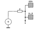
도 8 및 도 9는, 생성기 전극에서 정전용량성 부하의 측정을 행하는 본 변형예를 도시한다. 이는 부하(C)에 대하여 수행될 수 있는데, 예를 들면, 생성기(G)와 생성기 전극(EL_B) 사이에 연결된 연결 임피던스(Z)에서 전압 강하(도식적으로 신호(S)로)를 측정한다. 접촉을 검출하는 이 방법은, 어떤 애플리케이션들에서의 전극들이 최소 비용으로 구현될 수 있다는 장점을 갖는다. 도 11에서, 모든 위치 검출 전극들(EL_P)이 생성기 전극들(GEN)과 함께 더작은 유닛들(타블렛들)로서 만들어질 수 있는 전극 구성이 도시되어 있다. Figs. 8 and 9 show the present modification in which the measurement of the electrostatic capacitive load is performed at the generator electrode. This can be done for the load C, for example, by measuring the voltage drop (graphically to the signal S) at the connection impedance Z connected between the generator G and the generator electrode EL_B. This method of detecting the contact has the advantage that the electrodes in some applications can be implemented at the lowest cost. In Fig. 11, an electrode configuration is shown in which all the position detecting electrodes EL_P can be made as smaller units (tablets) together with the generator electrodes GEN.
대안적으로, 키보드의 사용과 모션 검출(마우스 기능) 사이의 구분은, 다음의 방식으로 수행된다: 스위칭 영역들이 키보드에서 정의되고, 장치가 마우스 모드로 스위칭됨으로써 시작된다. 이러한 스위칭 영역들(에를 들면, 도 12의 EB1 및 EB2)은 바람직하게 기존의 전극들상에 정의될 수 있다. 그들의 정의는 왼손을 위해, 오른손을 위해, 또는 양손을 위해 적용될 수 있다. Alternatively, the distinction between the use of the keyboard and the motion detection (mouse function) is performed in the following manner: switching areas are defined on the keyboard and the device is started by switching to the mouse mode. These switching regions (for example, EB1 and EB2 in Fig. 12) can preferably be defined on existing electrodes. Their definition can be applied for the left hand, for the right hand, or for both hands.
본 발명의 기능은 다음과 같다:The functions of the present invention are as follows:
(a) 사용자가 키보드상에서 작업한다. 사용자가 스위칭 영역들의 어디라도 터치하지 않는 한, 제스처 데이터는 평가되지 않는다.(a) The user works on the keyboard. Gesture data is not evaluated unless the user touches any of the switching areas.
(b) 사용자가 스위칭 영역들의 하나 또는 둘을 손가락으로 터치하기 위해 왼손을 놓는다(도 13). 이 순간, 사용자의 오른손의 움직임들은 마우스 움직임들로 해석되고, 마우스의 클릭들은 하나 또는 다른 스위칭 영역을 터치함으로써 수행된다. 이러한 경우에서, 접촉 검출 전극은 불필요하며, 그 위치에는 도 12에서 EL_B/GEN으로 표시된 것과 같은 생성기 전극이 이용될 수 있다. (b) The user places his left hand to touch one or both of the switching areas with his finger (Fig. 13). At this moment, the movements of the user's right hand are interpreted as mouse movements, and the mouse clicks are performed by touching one or the other switching area. In this case, the contact detection electrode is unnecessary, and a generator electrode such as EL_B / GEN in Fig. 12 can be used at that position.
또한, 비교가능 기능성이, 다른손 할당들과 함께 일어날 수 있다. Also, comparable functionality can occur with other hand allocations.
마우스 모드에서 클릭들의 검출을 위한 본 발명의 또다른 실시예에서는, 입력 장치가 이 모드로 되자마자, 키보드에서의 모든 키 활성화가 마우스 클릭으로 해석된다. In another embodiment of the present invention for detecting clicks in mouse mode, as soon as the input device enters this mode, all key activation on the keyboard is interpreted as a mouse click.
본 발명의 기능은 다음과 같다:The functions of the present invention are as follows:
(a) 사용자가 키보드상에서 작업한다. 마우스 모드가 활성화되지 않는 한, 제스처 데이터는 평가되지 않는다. (a) The user works on the keyboard. As long as the mouse mode is not activated, the gesture data is not evaluated.
(b) 사용자는 앞서 설명된 방식들 중 하나로, 입력 장치의 마우스 모드를 활성화시킨다. 이 순간부터, 사용자 손의 움직임들은 마우스 움직임들로 해석되고, 그 순간에 사용자의 손가락 또는 손 아래의 어느 키보드키의 활성화에 의해 마우스의 클릭들이 수행된다. 이 경우에 있어서, 접촉 검출 전극은 불필요하고, 그것의 위치에는, 도 12에서 EL_B/GEN으로 표시된 바와 같은 생성기 전극이 이용될 수 있다. (b) The user activates the mouse mode of the input device in one of the ways described above. From this moment, the movements of the user's hand are interpreted as mouse movements, and at that moment the mouse's clicks are performed by activating any keyboard keys under the user's fingers or hands. In this case, the contact detecting electrode is unnecessary, and at this position, a generator electrode as indicated by EL_B / GEN in Fig. 12 can be used.
본 발명의 또다른 적용 분야가 도 14에 도시되었다. 여기서, 장치(VT)는, 키들을 갖지 않으며, 극단적으로는 확장된 마우스 패드와 같이 보인다. 이 장치는, 컴퓨터를 이용할 때 이용되는, 키보드 및 포인팅 장치로서 동작한다. 키보드에서의 작업을 위하여, 가상 키보드가 스크린에 보여진다(앞서 설명된 숫자 패드와 유사함). 그것은, 촉각적인 피드백을 생성하기 위한 전기적으로 동작불가한 키들을 포함할 수도 있다. 하지만, 키들은 완전히 생략될 수도 있으며, 선택적으로는 방향(orientation)에 대한 영역에 인쇄될 수도 있다. 키보드는, 스크린상의 다른 애플리케이션들 위에 반투명한 가이드로서 표시될 수 있으며 또는 스크린의 (전용의)일부에 표시될 수도 있고, 커서 제어는 상술한 바와 같은 제스처에 의해 수행된다. 이 필드는 얇은 탄성 코팅으로 구비될 수도 있다. 키의 확정적인 선택 또는 활성화는, 결정된 접촉 압력 또는 결정된 동적 프로파일을 초과할 때에만 수행된다. Another application of the present invention is shown in Fig. Here, the device VT does not have keys, and looks like an extensively extended mouse pad. This device operates as a keyboard and a pointing device, which is used when using a computer. For work on the keyboard, a virtual keyboard is shown on the screen (similar to the numeric pad described above). It may include electrically inoperable keys for generating tactile feedback. However, the keys may be omitted altogether and, optionally, may be printed in an area for orientation. The keyboard may be displayed as a translucent guide over other applications on the screen or may be displayed on a (dedicated) portion of the screen, and cursor control is performed by a gesture as described above. This field may be provided with a thin elastic coating. The deterministic selection or activation of the key is performed only when the determined contact pressure or determined dynamic profile is exceeded.
전극들의 상술한 형태는 예시일 뿐이다. 또한, 특히, 전극들의 형태 및 그들의 관련된 위치가 서로 다른 형태들도 가능하다. The above-described form of electrodes is only an example. Also, in particular, different forms of electrodes and their associated positions are possible.
Claims (18)
상기 키보드는:
적어도 하나의 생성기 전극과 복수의 검출 전극들을 포함하는, 상기 키보드 내에 통합된 전극 배열 - 상기 검출 전극들 중 적어도 하나와 상기 적어도 하나의 생성기 전극은 상기 다수의 수동으로 조작가능한 키들의 아래(under) 영역에 배열되고, 상기 생성기 전극은 상기 생성기 전극과 상기 검출 전극들 사이에 전기장을 생성하는 구동 신호를 수신함 -; 및
상기 입력 장치 위에 위치하는 영역 내에서 상기 입력 장치를 터치하지 않는 손가락 또는 손의 위치 및 움직임 중 적어도 하나를 검출하기 위해서 상기 검출 전극들로부터의 복수의 신호들을 수신하고, 그리고 상기 손가락 또는 손에 의해 형성된 제스처를 해석하도록 추가로 구성된 평가 회로;를 포함하는 입력 장치.An input device having a keyboard including a plurality of manually operable keys,
The keyboard comprises:
Wherein at least one of the sensing electrodes and the at least one generator electrode are disposed underneath the plurality of manually operable keys, Wherein the generator electrode receives a drive signal to generate an electric field between the generator electrode and the detection electrodes; And
Receiving a plurality of signals from the detection electrodes to detect at least one of a position and a movement of a finger or a hand that does not touch the input device within an area located above the input device, And an evaluation circuit further configured to interpret the formed gesture.
사용자에 의한 터치를 검출하도록 구성된 적어도 하나의 제1 전극을 더 포함하고,
상기 제1 전극에서 터치를 검출하면 상기 입력 장치가 키보드 모드로부터 제스처 검출 모드로 스위칭되는 입력 장치.The method according to claim 1,
Further comprising at least one first electrode configured to detect a touch by a user,
And the input device is switched from the keyboard mode to the gesture detection mode when a touch is detected at the first electrode.
터치를 검출하도록 구성된 적어도 하나의 제2 전극을 더 포함하고,
상기 제2 전극에서 터치를 검출하면 마우스 클릭과 동등한 신호가 생성되는 입력 장치.The method according to claim 1,
Further comprising at least one second electrode configured to detect a touch,
Wherein when a touch is detected at the second electrode, a signal equivalent to a mouse click is generated.
상기 다수의 수동으로 조작가능한 키들 아래에 그리고 상기 다수의 수동으로 조작가능한 키들을 둘러싸도록 배열된 접촉 검출 전극을 더 포함하는 입력 장치.The method of claim 3,
And a contact detection electrode arranged to surround the plurality of manually operable keys and the plurality of manually operable keys.
상기 복수의 검출 전극들은 상기 다수의 수동으로 조작가능한 키들의 둘레에 배열되는 입력 장치.5. The method according to any one of claims 1 to 4,
Wherein the plurality of detection electrodes are arranged around the plurality of manually operable keys.
상기 생성기 전극은 상기 복수의 검출 전극들 아래의 층 내에 배열되는 입력 장치.5. The method according to any one of claims 1 to 4,
Wherein the generator electrode is arranged in a layer below the plurality of detection electrodes.
상기 평가 회로는 키보드, 숫자 키보드, 또는 기능 키들이 상기 입력 장치와 관련된 스크린상에 보여지는 것을 개시하게 하는 신호들을 생성하도록 구성되는 입력 장치.5. The method according to any one of claims 1 to 4,
Wherein the evaluation circuit is configured to generate signals that cause a keyboard, numeric keyboard, or function keys to be displayed on the screen associated with the input device.
상기 생성기 전극은 링-형상이고 그리고 상기 입력 장치의 가장자리를 따라 배열된 상기 검출 전극들의 아래에 배열되는 입력 장치.The method according to claim 6,
Wherein the generator electrodes are ring-shaped and are arranged below the detection electrodes arranged along an edge of the input device.
상기 검출 전극들은, 오른쪽 작업손의 손 또는 손가락 움직임들을 검출하기 위한 하나의 전극 서브그룹과, 왼쪽 작업손의 손 또는 손가락 움직임들을 검출하기 위한 하나의 전극 서브그룹이 존재하도록 그룹지어지고 배열되는 입력 장치.5. The method according to any one of claims 1 to 4,
Wherein the detection electrodes comprise one electrode subgroup for detecting hand or finger movements of the right hand and an input grouped and arranged such that there is one electrode subgroup for detecting hand or finger movements of the left hand Device.
제스처의 종료(conclusion)를 나타내기 위한 클로징 신호가 상기 키보드의 부품을 터치함으로써 생성되는 입력 장치.5. The method according to any one of claims 1 to 4,
Wherein a closing signal for indicating a conclusion of the gesture is generated by touching a part of the keyboard.
한 손에 의해 연계되는(coordinated) 제스처의 클로징 신호는 다른 손이 키보드 부품과 접촉함으로써 생성되는 입력 장치.5. The method according to any one of claims 1 to 4,
A closing signal of a gesture coordinated by one hand is generated when the other hand is brought into contact with the keyboard part.
상기 다수의 수동으로 조작가능한 키들은 전기적으로 동작이 불가능할 수 있는 입력 장치.5. The method according to any one of claims 1 to 4,
Wherein the plurality of manually operable keys may be electrically inoperable.
복수의 생성기 전극들이 제공되고,
각 생성기 전극은 각자의 검출 전극과 관련되고 상기 관련된 검출 전극의 아래에 배열되는 컴퓨터 키보드.A computer keyboard according to claim 6,
A plurality of generator electrodes are provided,
Each generator electrode being associated with a respective sensing electrode and being arranged below said associated sensing electrode.
상기 디스플레이 장치의 전방에 배치된 영역 내에서 상기 사용자의 손가락의 위치를 검출하기 위한 전극 장치를, 상기 디스플레이 장치의 상기 영역 내에 더 포함하는 컴퓨터.15. The method of claim 14,
Further comprising an electrode device for detecting the position of the user's finger within an area disposed in front of the display device within the area of the display device.
Applications Claiming Priority (3)
| Application Number | Priority Date | Filing Date | Title |
|---|---|---|---|
| DE102010007698 | 2010-02-10 | ||
| DE102010007698.8 | 2010-02-10 | ||
| PCT/EP2011/000638 WO2011098280A1 (en) | 2010-02-10 | 2011-02-10 | Computer keyboard with integrated an electrode arrangement |
Publications (2)
| Publication Number | Publication Date |
|---|---|
| KR20130002983A KR20130002983A (en) | 2013-01-08 |
| KR101749956B1 true KR101749956B1 (en) | 2017-06-22 |
Family
ID=44061942
Family Applications (1)
| Application Number | Title | Priority Date | Filing Date |
|---|---|---|---|
| KR1020127021392A Active KR101749956B1 (en) | 2010-02-10 | 2011-02-10 | Computer keyboard with integrated an electrode arrangement |
Country Status (6)
| Country | Link |
|---|---|
| US (1) | US9946409B2 (en) |
| EP (1) | EP2534561B1 (en) |
| KR (1) | KR101749956B1 (en) |
| CN (1) | CN102870079B (en) |
| DE (1) | DE102011010914A1 (en) |
| WO (1) | WO2011098280A1 (en) |
Families Citing this family (14)
| Publication number | Priority date | Publication date | Assignee | Title |
|---|---|---|---|---|
| EP2534561B1 (en) | 2010-02-10 | 2018-08-08 | Microchip Technology Germany GmbH | Computer keyboard with integrated an electrode arrangement |
| US9285889B2 (en) * | 2012-12-10 | 2016-03-15 | Intel Corporation | Electrode arrangement for a keyboard proximity and tracking sensor |
| GB2513744B (en) * | 2012-12-10 | 2020-10-21 | Intel Corp | Electrode arrangement for a keyboard proximity and tracking sensor |
| US9703389B2 (en) * | 2012-12-24 | 2017-07-11 | Peigen Jiang | Computer input device |
| US10352976B2 (en) | 2013-03-15 | 2019-07-16 | Microchip Technology Incorporated | Matrix electrode design for three-dimensional e-filed sensor |
| US9063578B2 (en) * | 2013-07-31 | 2015-06-23 | Microsoft Technology Licensing, Llc | Ergonomic physical interaction zone cursor mapping |
| CN105593784A (en) * | 2013-09-30 | 2016-05-18 | 惠普发展公司,有限责任合伙企业 | keyboard and touchpad area |
| US10963159B2 (en) * | 2016-01-26 | 2021-03-30 | Lenovo (Singapore) Pte. Ltd. | Virtual interface offset |
| KR20170124068A (en) | 2016-05-01 | 2017-11-09 | (주)이노프레소 | Electrical device having multi-functional human interface |
| CN109375783B (en) * | 2016-06-23 | 2022-03-11 | 株式会社音乐派索 | Electronic equipment with multifunctional man-machine interface |
| US10877554B2 (en) | 2018-04-19 | 2020-12-29 | Samsung Electronics Co., Ltd. | High efficiency input apparatus and method for virtual reality and augmented reality |
| US11237598B2 (en) * | 2018-11-15 | 2022-02-01 | Dell Products, L.P. | Application management for multi-form factor information handling system (IHS) |
| USD918654S1 (en) | 2019-06-06 | 2021-05-11 | Sharkninja Operating Llc | Grill plate |
| CN117093079A (en) * | 2023-09-25 | 2023-11-21 | 西南大学 | Portable touch interactive keyboard |
Citations (3)
| Publication number | Priority date | Publication date | Assignee | Title |
|---|---|---|---|---|
| US20030025679A1 (en) * | 1999-06-22 | 2003-02-06 | Cirque Corporation | System for disposing a proximity sensitive touchpad behind a mobile phone keypad |
| US20080158172A1 (en) * | 2007-01-03 | 2008-07-03 | Apple Computer, Inc. | Proximity and multi-touch sensor detection and demodulation |
| US20080284736A1 (en) * | 2007-05-14 | 2008-11-20 | Synaptics Incorporated | Proximity sensor device and method with keyboard emulation |
Family Cites Families (20)
| Publication number | Priority date | Publication date | Assignee | Title |
|---|---|---|---|---|
| US5502460A (en) | 1993-05-26 | 1996-03-26 | Bowen; James H. | Ergonomic laptop computer and ergonomic keyboard |
| US6204839B1 (en) * | 1997-06-27 | 2001-03-20 | Compaq Computer Corporation | Capacitive sensing keyboard and pointing device |
| KR100595926B1 (en) * | 1998-01-26 | 2006-07-05 | 웨인 웨스터만 | Method and apparatus for integrating manual input |
| US6535200B2 (en) * | 1999-01-25 | 2003-03-18 | Harald Philipp | Capacitive position sensor |
| CN1208230C (en) * | 2000-03-31 | 2005-06-29 | 因温特奥股份公司 | Apparatus and method for reducing mains connection power of elevator installations |
| US6680677B1 (en) | 2000-10-06 | 2004-01-20 | Logitech Europe S.A. | Proximity detector to indicate function of a key |
| US8773351B2 (en) * | 2001-05-21 | 2014-07-08 | Sony Corporation | User input apparatus, computer connected to user input apparatus, method of controlling computer connected to user input apparatus, and storage medium |
| US7737965B2 (en) | 2005-06-09 | 2010-06-15 | Honeywell International Inc. | Handheld synthetic vision device |
| US7813774B2 (en) | 2006-08-18 | 2010-10-12 | Microsoft Corporation | Contact, motion and position sensing circuitry providing data entry associated with keypad and touchpad |
| WO2008059795A1 (en) * | 2006-11-15 | 2008-05-22 | Alps Electric Co., Ltd. | Operational direction detecting apparatus |
| US7877707B2 (en) | 2007-01-06 | 2011-01-25 | Apple Inc. | Detecting and interpreting real-world and security gestures on touch and hover sensitive devices |
| JP5183494B2 (en) * | 2007-01-31 | 2013-04-17 | アルプス電気株式会社 | Capacitance type motion detection device and input device using the same |
| US20080203734A1 (en) * | 2007-02-22 | 2008-08-28 | Mark Francis Grimes | Wellbore rig generator engine power control |
| US8093914B2 (en) * | 2007-12-14 | 2012-01-10 | Cypress Semiconductor Corporation | Compensation circuit for a TX-RX capacitive sensor |
| US8358277B2 (en) * | 2008-03-18 | 2013-01-22 | Microsoft Corporation | Virtual keyboard based activation and dismissal |
| TWI460622B (en) * | 2008-06-20 | 2014-11-11 | Elan Microelectronics | Touch pad module capable of interpreting multi-object gestures and operating method thereof |
| US10585493B2 (en) * | 2008-12-12 | 2020-03-10 | Apple Inc. | Touch sensitive mechanical keyboard |
| EP2534561B1 (en) | 2010-02-10 | 2018-08-08 | Microchip Technology Germany GmbH | Computer keyboard with integrated an electrode arrangement |
| US8432301B2 (en) * | 2010-08-10 | 2013-04-30 | Mckesson Financial Holdings | Gesture-enabled keyboard and associated apparatus and computer-readable storage medium |
| US8816964B2 (en) * | 2010-11-26 | 2014-08-26 | Mckesson Financial Holdings | Sensor-augmented, gesture-enabled keyboard and associated apparatus and computer-readable storage medium |
-
2011
- 2011-02-10 EP EP11716367.5A patent/EP2534561B1/en active Active
- 2011-02-10 WO PCT/EP2011/000638 patent/WO2011098280A1/en not_active Ceased
- 2011-02-10 KR KR1020127021392A patent/KR101749956B1/en active Active
- 2011-02-10 US US13/577,614 patent/US9946409B2/en active Active
- 2011-02-10 CN CN201180008868.0A patent/CN102870079B/en active Active
- 2011-02-10 DE DE102011010914A patent/DE102011010914A1/en active Pending
Patent Citations (3)
| Publication number | Priority date | Publication date | Assignee | Title |
|---|---|---|---|---|
| US20030025679A1 (en) * | 1999-06-22 | 2003-02-06 | Cirque Corporation | System for disposing a proximity sensitive touchpad behind a mobile phone keypad |
| US20080158172A1 (en) * | 2007-01-03 | 2008-07-03 | Apple Computer, Inc. | Proximity and multi-touch sensor detection and demodulation |
| US20080284736A1 (en) * | 2007-05-14 | 2008-11-20 | Synaptics Incorporated | Proximity sensor device and method with keyboard emulation |
Also Published As
| Publication number | Publication date |
|---|---|
| DE102011010914A1 (en) | 2011-08-11 |
| WO2011098280A1 (en) | 2011-08-18 |
| US9946409B2 (en) | 2018-04-17 |
| EP2534561A1 (en) | 2012-12-19 |
| US20130050092A1 (en) | 2013-02-28 |
| EP2534561B1 (en) | 2018-08-08 |
| CN102870079A (en) | 2013-01-09 |
| KR20130002983A (en) | 2013-01-08 |
| CN102870079B (en) | 2016-09-07 |
Similar Documents
| Publication | Publication Date | Title |
|---|---|---|
| KR101749956B1 (en) | Computer keyboard with integrated an electrode arrangement | |
| US11886699B2 (en) | Selective rejection of touch contacts in an edge region of a touch surface | |
| JP5764209B2 (en) | Movement sensing device and movement sensing method using proximity sensor | |
| US20110221684A1 (en) | Touch-sensitive input device, mobile device and method for operating a touch-sensitive input device | |
| CN100514267C (en) | Pointing device and method of inputting data into a device having a display screen | |
| US11216121B2 (en) | Smart touch pad device | |
| TWI439922B (en) | Handheld electronic apparatus and control method thereof | |
| AU2013100574B4 (en) | Interpreting touch contacts on a touch surface | |
| KR20160000534U (en) | Smartphone having touch pad | |
| AU2015271962B2 (en) | Interpreting touch contacts on a touch surface | |
| KR101631069B1 (en) | An integrated exclusive input platform supporting seamless input mode switching through multi-touch trackpad | |
| KR20140100668A (en) | Smart Device Cover and Smart Device having the same | |
| HK1169182A (en) | Selective rejection of touch contacts in an edge region of a touch surface | |
| HK1133709A (en) | Selective rejection of touch contacts in an edge region of a touch surface |
Legal Events
| Date | Code | Title | Description |
|---|---|---|---|
| PA0105 | International application |
Patent event date: 20120814 Patent event code: PA01051R01D Comment text: International Patent Application |
|
| PG1501 | Laying open of application | ||
| A201 | Request for examination | ||
| PA0201 | Request for examination |
Patent event code: PA02012R01D Patent event date: 20160211 Comment text: Request for Examination of Application |
|
| N231 | Notification of change of applicant | ||
| PN2301 | Change of applicant |
Patent event date: 20160801 Comment text: Notification of Change of Applicant Patent event code: PN23011R01D |
|
| E902 | Notification of reason for refusal | ||
| PE0902 | Notice of grounds for rejection |
Comment text: Notification of reason for refusal Patent event date: 20161014 Patent event code: PE09021S01D |
|
| E701 | Decision to grant or registration of patent right | ||
| PE0701 | Decision of registration |
Patent event code: PE07011S01D Comment text: Decision to Grant Registration Patent event date: 20170420 |
|
| GRNT | Written decision to grant | ||
| PR0701 | Registration of establishment |
Comment text: Registration of Establishment Patent event date: 20170616 Patent event code: PR07011E01D |
|
| PR1002 | Payment of registration fee |
Payment date: 20170619 End annual number: 3 Start annual number: 1 |
|
| PG1601 | Publication of registration | ||
| PR1001 | Payment of annual fee |
Payment date: 20210525 Start annual number: 5 End annual number: 5 |
|
| PR1001 | Payment of annual fee |
Payment date: 20240527 Start annual number: 8 End annual number: 8 |