KR101699014B1 - Method for detecting object using stereo camera and apparatus thereof - Google Patents
Method for detecting object using stereo camera and apparatus thereof Download PDFInfo
- Publication number
- KR101699014B1 KR101699014B1 KR1020150176975A KR20150176975A KR101699014B1 KR 101699014 B1 KR101699014 B1 KR 101699014B1 KR 1020150176975 A KR1020150176975 A KR 1020150176975A KR 20150176975 A KR20150176975 A KR 20150176975A KR 101699014 B1 KR101699014 B1 KR 101699014B1
- Authority
- KR
- South Korea
- Prior art keywords
- interest
- roi
- height
- region
- map
- Prior art date
- Legal status (The legal status is an assumption and is not a legal conclusion. Google has not performed a legal analysis and makes no representation as to the accuracy of the status listed.)
- Active
Links
Images


Classifications
-
- H04N13/0271—
-
- H04N13/0022—
-
- H04N13/0048—
-
- H04N13/02—
Landscapes
- Image Analysis (AREA)
Abstract
본 발명은 스테레오 카메라를 이용한 객체 검출 방법 및 장치에 관한 것이다. 본 발명에 따르면, 스테레오 카메라의 영상에서 획득한 깊이 지도를 이용하여 V-시차맵과 U-시차맵을 각각 생성하는 단계와, 상기 V-시차맵과 상기 U-시차맵을 통해 상기 영상에 생성되는 복수의 관심 영역에 대한 위치와 크기를 결정하되, 기 설정된 관심 객체의 대표 높이 값을 고려하여 상기 관심 영역의 높이를 조절하는 단계와, 상기 복수의 관심 영역 중에서 상호 중첩 영역을 가지는 중복 관심 영역들을 단일의 관심 영역으로 통합하는 단계, 및 각각의 상기 관심 영역 내에서 상기 관심 객체가 존재하는지 판별하고 상기 관심 객체의 검출 결과를 출력하는 단계를 포함하는 스테레오 카메라를 이용한 객체 검출 방법을 제공한다.
상기 객체 검출 방법 및 장치에 따르면, 관심 객체의 높이를 반영하여 관심 영역의 크기를 조절하며 유사도가 높은 중복 관심 영역들을 정리하여 객체를 검출함에 따라 객체 검출에 소요되는 탐색 영역을 줄이고 검출 속도 및 성능을 동시에 향상시킬 수 있다.The present invention relates to a method and an apparatus for detecting an object using a stereo camera. According to another aspect of the present invention, there is provided a method of generating a stereoscopic image, the method comprising: generating a V-disparity map and a U-disparity map using a depth map acquired from an image of a stereo camera; Determining a position and a size of a plurality of ROIs by adjusting a height of the ROI in consideration of a representative height value of a predetermined ROI; Integrating the objects of interest into a single area of interest, and outputting the detection results of the objects of interest in each of the areas of interest, determining whether the objects of interest are present.
According to the object detection method and apparatus, the size of the region of interest is adjusted by reflecting the height of the object of interest, and the object region is detected by arranging the overlapping regions of interest with high similarity, thereby reducing the search region required for object detection, Can be improved at the same time.
Description
본 발명은 스테레오 카메라를 이용한 객체 검출 방법 및 장치에 관한 것으로서 보다 상세하게는 검출 속도와 성능을 향상시킬 수 있는 스테레오 카메라를 이용한 객체 검출 방법 및 장치에 관한 것이다.The present invention relates to a method and apparatus for detecting an object using a stereo camera, and more particularly, to a method and apparatus for detecting an object using a stereo camera capable of improving detection speed and performance.
보행자 검출 기술은 지능형 자동차, 로봇, 영상 보안 등의 다양한 분야에서 활용되고 있다. 최근 10년간 관련 논문이 1000편 이상 발표되는 등 활발한 연구가 진행되고 있으며 보행자 검출 성능이 점차 향상되고 있다. Pedestrian detection technology is used in various fields such as intelligent automobile, robot, and video security. More than 1000 related papers have been published over the past 10 years, and active research is underway, and pedestrian detection performance is gradually improving.
보행자 검출 기술은 ADAS(Advanced Driver Assistance Systems)와 같이 지능형 자동차에 적용되어 운전자를 보조함과 동시에 보행자의 생명도 보호한다. 보행자 검출 기술의 정확도와 실시간성은 보행자의 생명과 연관되기 때문에 매우 중요하다. Pedestrian detection technology is applied to intelligent vehicles such as Advanced Driver Assistance Systems (ADAS), which assists the driver and protects the lives of pedestrians. The accuracy and real - time nature of the pedestrian detection technique is very important because it is related to the life of the pedestrian.
보행자 검출은 카메라의 이미지로부터 보행자를 찾는 기술로서, 학습 이미지에서 특징을 추출하여 학습한 다음 이를 이용하여 테스트 이미지를 탐색하면서 보행자를 검출한다. 보행자 검출을 위하여 사용하는 대표적인 특징으로 HOG(Histogram of Oriented Gradients)가 있다.Pedestrian detection is a technique for finding a pedestrian from an image of a camera. The pedestrian is detected by extracting features from a learning image and then searching for a test image using the feature. HOG (Histogram of Oriented Gradients) is a typical feature used for pedestrian detection.
일반적인 보행자 검출 기법은 HOG와 같은 특징을 기반으로 테스트 이미지에서 다중 스케일 슬라이딩 윈도우(multi-scale sliding window) 방식으로 탐색을 하며, SVM(Support Vector Machine)과 같은 분류기(classifier)를 사용하여 보행자의 위치, 이미지 스케일(image scale)을 찾는다. 그리고 NMS(non-maximum suppression)와 같은 기법을 이용하여 검출한 객체에서 불필요한 결과들을 제거한다. 다중 스케일 슬라이딩 윈도우 기법은 구조가 간단하지만 모든 영역을 탐색하기 때문에 처리 속도가 매우 느리다.A typical pedestrian detection method searches for a multi-scale sliding window in a test image based on characteristics such as HOG, and uses a classifier such as SVM (Support Vector Machine) , And image scale. And eliminates unnecessary results from the detected objects using techniques such as NMS (non-maximum suppression). The multi-scale sliding window technique is simple in structure, but its processing speed is very slow because it searches all areas.
단일 카메라 기반의 보행자 검출 기법들은 다중 스케일 슬라이딩 윈도우 기법을 기반으로 보행자를 탐색하고 찾는다. 이러한 방법들은 사전의 정보(prior information) 또는 추가적인 정보가 없으면 탐색 영역을 줄일 수 없기 때문에 검출 속도를 향상시키는데 한계가 있다.Single camera based pedestrian detection techniques search and search for pedestrians based on multi - scale sliding window technique. These methods have limitations in improving the detection speed because they can not reduce the search area without prior information or additional information.
스테레오 카메라 기반의 객체 검출 기법은 두 카메라의 시차(disparity)를 이용하여 깊이 지도를 생성하고 이를 이용하여 각 객체들을 추출한다. 스테레오 카메라의 깊이 지도(depth map)을 이용하면 관심영역(ROI: region of interest)의 정보를 빠르게 얻을 수 있으며 이를 이용하여 객체 탐색 영역을 줄여 속도와 성능 향상이 가능해진다. Stereo camera based object detection method generates depth map using disparity of two cameras and extracts each object using it. Using a depth map of a stereo camera, information of a region of interest (ROI) can be obtained quickly, and the speed and performance of the object can be improved by reducing the object search area.
그런데, 스테레오 카메라로부터 획득된 깊이 지도는 일반적으로 스테레오 매칭 에러(stereo matching error)가 존재한다. 이와 같은 매칭 에러로 인해 관심 영역 생성 시에 오차가 발생할 수 있으며 분류기(classifier)로 검출하지 못하는 객체가 발생할 수 있는 문제점이 있다.However, a depth map obtained from a stereo camera generally has a stereo matching error. Such a matching error may cause an error in generating a region of interest, and an object that can not be detected as a classifier may occur.
본 발명의 배경이 되는 기술은 한국등록특허 제0929569호(2009.12.03 공고)에 개시되어 있다.The technology that provides the background of the present invention is disclosed in Korean Patent No. 0929569 (published on Dec. 3, 2009).
본 발명은, 객체 탐색 영역을 줄여 검출 속도 및 성능을 향상시킬 수 있는 스테레오 카메라를 이용한 객체 검출 방법 및 장치를 제공하는데 목적이 있다.An object of the present invention is to provide a method and an apparatus for detecting an object using a stereo camera capable of reducing detection speed and performance by reducing an object search area.
본 발명은, 스테레오 카메라의 영상에서 획득한 깊이 지도를 이용하여 V-시차맵과 U-시차맵을 각각 생성하는 단계와, 상기 V-시차맵과 상기 U-시차맵을 통해 상기 영상에 생성되는 복수의 관심 영역에 대한 위치와 크기를 결정하되, 기 설정된 관심 객체의 대표 높이 값을 고려하여 상기 관심 영역의 높이를 조절하는 단계와, 상기 복수의 관심 영역 중에서 상호 중첩 영역을 가지는 중복 관심 영역들을 단일의 관심 영역으로 통합하는 단계, 및 각각의 상기 관심 영역 내에서 상기 관심 객체가 존재하는지 판별하고 상기 관심 객체의 검출 결과를 출력하는 단계를 포함하는 스테레오 카메라를 이용한 객체 검출 방법을 제공한다.The present invention provides a method of generating stereoscopic images, the method comprising: generating a V-parallax map and a U-parallax map using a depth map obtained from an image of a stereo camera, Determining a position and a size of a plurality of ROIs, adjusting a height of the ROI in consideration of a representative height value of a predetermined ROI, determining overlapping ROIs having overlapping ROIs among the ROIs, Integrating the object of interest into a single region of interest, and determining whether the object of interest exists in each of the regions of interest and outputting a detection result of the object of interest.
여기서, 상기 관심 영역의 높이를 조절하는 단계는, 상기 U-시차맵 및 상기 V-시차맵을 이용하여, 상기 영상 내에서 상기 관심 영역의 가로 위치와 폭 및 세로 위치와 높이를 결정하되, 상기 V-시차맵에서 검출되는 상기 관심 영역의 높이 시작점에 상기 관심 객체의 대표 높이 값을 오프셋 시켜 획득한 높이 끝점을 이용하여 상기 관심 영역의 높이를 조절할 수 있다.Here, the step of adjusting the height of the ROI may include determining a horizontal position, a width, a vertical position and a height of the ROI in the image using the U-parallax map and the V-parallax map, The height of the ROI can be adjusted by using a height end point obtained by offsetting the representative height value of the ROI at the start point of the ROI detected in the V-parallax map.
또한, 상기 객체 검출 방법은, 상기 높이를 조절한 각각의 관심 영역의 크기를 기 설정된 배율로 확장시키는 단계를 더 포함할 수 있다.The object detection method may further include expanding a size of each region of interest in which the height is adjusted to a predetermined magnification.
또한, 상기 중복 관심 영역들을 통합하는 단계는, 상기 중복 관심 영역들 간의 유사도를 연산한 다음, 상기 유사도가 임계치 이상으로 판단된 경우에 한하여 상기 중복 관심 영역들을 하나의 관심 영역으로 통합할 수 있다.In addition, the step of integrating the overlapping ROIs may include calculating the degree of similarity between the ROIs, and then combining the ROIs into one ROI only when the degree of similarity is determined to be equal to or greater than the threshold value.
또한, 상기 중복 관심 영역들을 통합하는 단계는, 상기 유사도에 해당하는 아래 수학식의 fs(hi,hj)이 임계치 이상이면 상기 중복 관심 영역들을 하나의 관심 영역으로 통합할 수 있다.Further, the step of integrating the overlapping region of interest is, when the s f (h i, h j) of the equation below corresponding to the threshold degree of similarity than can incorporate the overlapping region of interest in a region of interest.

여기서, fs(hi,hj)는 0과 1 사이의 값으로서 1에 가까울수록 상기 유사도가 높으며, fo(hi,hj)는 상호 중첩 영역을 가지는 제1 및 제2 관심 영역(hi,hj)의 전체 면적(Rhi∪Rhj) 대비한 중복 면적(Rhi∩Rhj)의 비이고, fd(hi,hj)는 상기 제1 및 제2 관심 영역(hi,hj)의 깊이 차(|dhi-dhj|)가 작을수록 커지는 값이고, λ는 기 설정된 임의의 양의 값을 나타낸다.Here, f s (h i , h j ) is a value between 0 and 1, the closest to 1, the higher the degree of similarity, and the f o (h i , h j ) the total area (R ∪R hi hj) and the ratio of the overlapping area (R ∩R hi hj) contrast, f d (h i, h j) are the first and second region of interest (h i, h j) (| d hi -d hj |) of the (h i , h j ), and λ represents a predetermined positive value.
그리고, 본 발명은 스테레오 카메라의 영상에서 획득한 깊이 지도를 이용하여 V-시차맵과 U-시차맵을 각각 생성하는 시차맵 생성부와, 상기 V-시차맵과 상기 U-시차맵을 통해 상기 영상에 생성되는 복수의 관심 영역에 대한 위치와 크기를 결정하되, 기 설정된 관심 객체의 대표 높이 값을 고려하여 상기 관심 영역의 높이를 조절하는 관심 영역 생성부와, 상기 복수의 관심 영역 중에서 상호 중첩 영역을 가지는 중복 관심 영역들을 단일의 관심 영역으로 통합하는 관심 영역 정리부와, 각각의 상기 관심 영역 내에서 상기 관심 객체가 존재하는지 판별하는 객체 검출부, 및 상기 관심 객체의 검출 결과를 출력하는 결과 출력부를 포함하는 스테레오 카메라를 이용한 객체 검출 장치를 제공한다.According to another aspect of the present invention, there is provided a stereoscopic image display apparatus comprising a parallax map generator for generating a V-parallax map and a U-parallax map using a depth map obtained from an image of a stereo camera, An interest region generation unit for determining a position and a size of a plurality of ROIs generated in an image and adjusting a height of the ROI by considering a representative height value of a predetermined ROI; An interest detection unit for detecting whether or not the ROI exists in each of the ROIs, and a result output unit outputting a detection result of the ROIs, And an object detecting apparatus using the stereo camera.
본 발명에 따른 스테레오 카메라를 이용한 객체 검출 방법 및 장치에 따르면, 관심 객체의 높이를 반영하여 관심 영역의 크기를 조절하며 유사도가 높은 중복 관심 영역들을 정리하여 객체를 검출함에 따라 객체 검출에 소요되는 탐색 영역을 줄이고 검출 속도 및 성능을 동시에 향상시킬 수 있는 이점이 있다.According to the method and apparatus for detecting an object using a stereo camera according to the present invention, the size of the region of interest is adjusted by reflecting the height of the object of interest and the overlapping ROIs having high similarity are arranged, There is an advantage that the area can be reduced and the detection speed and performance can be improved at the same time.
도 1은 본 발명의 실시예에 따른 스테레오 카메라를 이용한 객체 검출 장치의 구성을 나타낸 도면이다.
도 2는 본 발명의 실시예에 따른 객체 검출 기법을 요약한 도면이다.
도 3은 본 발명의 실시예에 따른 객체 검출 방법의 흐름을 나타낸 도면이다.
도 4는 본 발명의 실시예에서 스테레오 카메라의 영상을 이용하여 깊이 지도를 생성한 예를 나타낸 도면이다.
도 5는 도 4의 깊이 지도로부터 V-시차맵과 U-시차맵을 생성한 결과를 나타낸 도면이다.
도 6은 도 5에 도시된 V-시차맵을 나타낸 도면이다.
도 7은 도 5에서 보행자의 높이를 고려하여 관심 영역을 생성한 결과를 나타낸 도면이다.
도 8은 본 발명의 실시예에서 관심 영역의 정리 기법을 설명하는 도면이다.1 is a block diagram of an object detecting apparatus using a stereo camera according to an embodiment of the present invention.
2 is a block diagram of an object detection technique according to an embodiment of the present invention.
3 is a flowchart illustrating an object detection method according to an embodiment of the present invention.
4 is a diagram illustrating an example of generating a depth map using an image of a stereo camera in an embodiment of the present invention.
FIG. 5 is a diagram showing the results of generating the V-parallax map and the U-parallax map from the depth map of FIG. 4. FIG.
FIG. 6 is a view showing the V-parallax map shown in FIG. 5. FIG.
FIG. 7 is a diagram illustrating a result of generating a ROI considering the height of a pedestrian in FIG.
8 is a view for explaining a rearrangement technique of a region of interest in an embodiment of the present invention.
그러면 첨부한 도면을 참고로 하여 본 발명의 실시예에 대하여 본 발명이 속하는 기술 분야에서 통상의 지식을 가진 자가 용이하게 실시할 수 있도록 상세히 설명한다.Hereinafter, embodiments of the present invention will be described in detail with reference to the accompanying drawings so that those skilled in the art can easily carry out the present invention.
본 발명은 스테레오 카메라를 이용한 객체 검출 방법 및 장치에 관한 것으로, 스테레오 카메라의 영상으로부터 관심 영역들을 효과적으로 생성하는 기법과, 생성한 관심 영역의 크기를 보정하는 기법, 그리고 상호 유사도가 높은 중복 관심 영역들을 정리하는 기법을 사용하여, 객체의 탐색 영역을 줄일 수 있고 객체의 검출 속도 및 성능을 향상시킬 수 있는 방법을 제안한다.The present invention relates to a method and apparatus for detecting an object using a stereo camera, and more particularly, to a technique for effectively generating regions of interest from an image of a stereo camera, a technique for correcting the size of the generated region of interest, We propose a method that can reduce the object search area and improve the detection speed and performance of the object by using the summarization technique.
도 1은 본 발명의 실시예에 따른 스테레오 카메라를 이용한 객체 검출 장치의 구성을 나타낸 도면이고, 도 2는 본 발명의 실시예에 따른 객체 검출 기법을 요약한 도면이다.FIG. 1 is a block diagram of an object detecting apparatus using a stereo camera according to an embodiment of the present invention. FIG. 2 is a diagram illustrating an object detecting method according to an exemplary embodiment of the present invention.
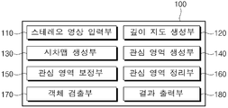
도 1 및 도 2를 참조하면, 본 발명의 실시예에 따른 객체 검출 장치(100)는 스테레오 영상 입력부(110), 깊이 지도 생성부(120), 시차맵 생성부(130), 관심 영역 생성부(140), 관심 영역 보정부(150), 관심 영역 정리부(160), 객체 검출부(170), 결과 출력부(180)를 포함한다.1 and 2, an
스테레오 영상 입력부(110)는 스테레오 카메라에서 촬상된 영상을 입력받는다. 구체적으로 스테레오 카메라의 좌·우 영상을 각각 입력받는다. 도 2의 (a)는 설명의 편의상 두 영상 중 하나를 나타낸 것이다.The stereo
깊이 지도 생성부(120)는 입력된 스테레오 카메라의 좌·우 영상을 이용하여 깊이 지도(Depth-map)를 생성한다. 깊이 지도는 도 2의 (b)와 같이 카메라로부터 가까운 곳은 밝은 값으로, 먼 곳은 어두운 값으로 나타난다.The depth
시차맵 생성부(130)는 깊이 지도를 이용하여 V-시차맵(V-Disparity Map)과 U-시차맵(U-Disparity Map)을 생성한다. V-시차맵과 U-시차맵은 영상 내에 객체 검출 대상이 되는 관심 영역들을 생성하는데 사용된다.The
본 발명의 실시예에서 깊이 지도 생성 과정, 시차맵 생성 과정, 관심 영역의 생성 과정은 기본적으로 기 공지된 방식을 사용하면 된다. 다만, 본 발명의 실시예의 경우 관심 영역의 생성 시에 관심 객체(ex, 보행자)의 높이를 고려하여 관심 영역의 높이를 조절하는 구성을 가진다.The depth map generation process, the parallax map generation process, and the ROI generation process may be basically used in the embodiment of the present invention. However, in the embodiment of the present invention, the height of the ROI is adjusted in consideration of the height of the object of interest (ex, pedestrian) when the ROI is generated.
관심 영역 생성부(140)는 V-시차맵과 상기 U-시차맵을 이용하여 영상에 생성되는 복수의 관심 영역에 대한 위치와 크기를 결정하되 기 설정된 관심 객체(ex, 보행자)의 대표 높이 값을 고려하여 각 관심 영역의 높이를 조절한다. 도 2의 (c)는 두 시차맵을 이용하되 보행자의 높이를 반영하여 영상 내에 복수의 관심 영역을 생성한 것을 나타낸다.The
관심 영역 보정부(150)는 앞서 생성한 초기 관심 영역의 크기를 확대 보정한다. 도 2의 (d)는 초기 관심 영역이 확대 보정된 모습이다. 보행자의 높이를 이용하여 생성된 초기 관심 영역들은 너무 타이트한 높이로 생성될 수 있는데, 관심 영역의 높이가 너무 작으면 추후 검출기에서 보행자를 탐색하지 못할 수도 있다. 때문에 관심 영역의 크기를 키우는 작업을 추가로 수행하여 탐색률을 높인다.The
관심 영역 정리부(160)는 관심 영역들 중에서 중복된 관심 영역을 정리하여 객체 탐색 영역을 줄이고 검출 속도를 높인다. 도 2의 (e)는 중복 관심 영역들이 단일화된 모습을 나타낸다. 이와 같이, 중복 관심 영역을 정리하는 이유는 스테레오 카메라를 이용한 객체 검출 방식의 경우 스테레오 매칭 에러로 인해 하나의 객체에 대해 다수의 관심 영역이 중복 생성될 수 있으며 이로 인해 객체 탐색 영역이 불필요하게 증가하고 검출 속도와 성능이 크게 떨어질 수 있기 때문이다.The interest
객체 검출부(170)는 각 관심 영역 내에 관심 객체가 존재하는지 판별한다. 객체 검출은 통상의 분류기를 사용할 수 있으며, 보행자가 존재하는 관심 영역을 판별할 수 있고 영상 내에 보행자가 어느 지점에 검출되었는지 확인할 수 있다.The
결과 출력부(180)는 객체 검출부(170)에 의한 보행자의 검출 결과를 화면에 출력한다. 도 2의 (f)는 영상 내에서 보행자가 검출된 지점을 별도의 박스(ex, 사각형)로 표시하여 제공한 것이다.The
이하에서는 본 발명의 실시예에 따른 스테레오 카메라를 이용한 객체 검출 방법에 관하여 더욱 상세히 설명한다. 도 3은 본 발명의 실시예에 따른 객체 검출 방법의 흐름을 나타낸 도면이다. 이하에서는 설명의 편의를 위해 관심 객체가 보행자인 것을 예시로 하여 설명한다. Hereinafter, a method for detecting an object using a stereo camera according to an embodiment of the present invention will be described in detail. 3 is a flowchart illustrating an object detection method according to an embodiment of the present invention. Hereinafter, for convenience of explanation, it is exemplified that the object of interest is a pedestrian.
먼저, 스테레오 영상 입력부(110)는 스테레오 카메라의 영상을 입력받으며(S310), 깊이 지도 생성부(120)는 입력된 스테레오 카메라 영상을 이용하여 깊이 지도를 생성한다(S320).First, the stereo
도 4는 본 발명의 실시예에서 스테레오 카메라의 영상을 이용하여 깊이 지도를 생성한 예를 나타낸 도면이다. 일반적인 스테레오 매칭 방법을 사용하여 좌우 이미지로부터 깊이 지도를 생성할 수 있다.4 is a diagram illustrating an example of generating a depth map using an image of a stereo camera in an embodiment of the present invention. You can generate a depth map from left and right images using a common stereo matching method.
깊이 지도를 구성하는 각 픽셀은 0(검은색)부터 255(흰색)까지의 밝기값을 가진다. 도 4를 참조하면 카메라로부터 먼 거리에 있을수록 어두운 색상으로 표현되는 것을 확인할 수 있다. 이와 같이 깊이 지도는 카메라로부터의 거리(깊이) 값을 밝기 정도로 표현한 것이다.Each pixel composing the depth map has a brightness value from 0 (black) to 255 (white). Referring to FIG. 4, it can be seen that the farther from the camera the darker the color is. Thus, the depth map represents the distance (depth) value from the camera to the brightness level.
이후, 시차맵 생성부(130)는 깊이 지도를 이용하여 V-시차맵과 U-시차맵을 생성한다(S330). 각각의 시차맵은 깊이 지도에 표현된 거리 값을 가로 또는 세로 방향으로 각각 축적하여 생성한 데이터이다. Thereafter, the parallax
도 5는 도 4의 깊이 지도로부터 V-시차맵과 U-시차맵을 생성한 결과를 나타낸 도면이다. 깊이 지도 영상의 좌측에 표현된 것이 V-시차맵이고 하측에 표현된 것이 U-시차맵이다.FIG. 5 is a diagram showing the results of generating the V-parallax map and the U-parallax map from the depth map of FIG. 4. FIG. It is the V-parallax map represented on the left side of the depth map image and the U-parallax map represented on the lower side.
도 5의 동그라미 부분과 같이, V-시차맵은 깊이 지도 영상에서 가로에 해당하는 거리 값을 축적시켜 얻은 데이터이다. V-시차맵의 가로축은 0~255 거리 값(가로축의 왼쪽:0, 오른쪽:255), 세로축은 깊이 지도 영상의 세로 축과 대응한다. 5, the V-disparity map is data obtained by accumulating the distance value corresponding to the width in the depth map image. The horizontal axis of the V-parallax map corresponds to a distance value of 0 to 255 (left of the horizontal axis: 0, right: 255), and the vertical axis corresponds to the vertical axis of the depth map image.
비슷한 원리로, U-시차맵은 깊이 지도 영상에서 세로에 해당하는 거리 값을 축적시킨 데이터로서 V-시차맵과 축적 방향만 다른 데이터이다. U-시차맵의 세로축은 0~255 거리 값(세로축의 상단:255, 하단:0), 가로축은 깊이 지도 영상의 가로 축과 대응한다.In a similar principle, the U-disparity map is data in which the distance value corresponding to the vertical is accumulated in the depth map image, and is different from the V-disparity map only in the accumulation direction. The vertical axis of the U-parallax map corresponds to a distance value of 0 to 255 (upper end of the vertical axis: 255, lower end: 0), and the horizontal axis corresponds to the horizontal axis of the depth map image.
도 6은 도 5에 도시된 V-시차맵을 나타낸 도면이다. 도 6은 설명의 편의를 위해 화면 배율이 조절된 것이다. V-시차맵에서 도로와 같은 평면 성분은 대각선 형태로, 도로 위의 장애 물체는 수직선 형태로 나타난다.FIG. 6 is a view showing the V-parallax map shown in FIG. 5. FIG. FIG. 6 shows a screen magnification adjusted for convenience of explanation. In the V-parallax map, the plane components such as roads are diagonally shaped, and the obstacles on the roads appear as vertical lines.
즉, 도 6에서 대각선 형태의 데이터는 도로 라인을 나타낸다. 도로에 장애 물체(나무, 차량, 보행자 등)가 전혀 없는 경우라면 V-시차맵 상에는 대각선 형태의 데이터만 나타난다. 도 6에서 세로 형태(수직 방향)의 데이터는 장애 물체를 나타낸다. 장애 물체는 V-시차맵 상에서 거리 값(밝기 값)이 세로 방향으로 일정한 형태를 가진다.That is, in FIG. 6, the diagonal type data represents a road line. If there are no obstacles (trees, vehicles, pedestrians, etc.) on the road, only diagonal data appears on the V-parallax map. In Fig. 6, the vertical data (vertical direction) represents an obstacle. The obstacle has a shape in which the distance value (brightness value) is constant in the vertical direction on the V-parallax map.
이와 같이 V-시차맵은 영상 내에서 대략적인 장애물의 세로 위치를 잡아주고, U-시차맵은 대략적인 장애물의 가로 위치를 잡아주는 역할을 한다. 즉, V-시차맵으로부터 관심 영역의 세로 위치와 크기를 담당하고, U-시차맵은 관심 영역의 가로 위치와 크기를 담당한다. In this way, the V-parallax map captures the approximate vertical position of the obstacle in the image, and the U-parallax map serves to approximate the horizontal position of the obstacle. That is, the U-disparity map takes charge of the vertical position and the size of the ROI from the V-disparity map, and the U-disparity map takes charge of the horizontal position and size of the ROI.
따라서, S330 단계에서 생성한 V-시차맵과 U-시차맵을 이용하면 영상 내에서 관심 영역들을 생성할 수 있다. V-시차맵과 U-시차맵의 데이터만 이용하면 초기 관심 영역이 많고 크기가 크므로, 본 발명의 실시예는 보행자의 높이를 고려하여 개별 관심 영역의 높이를 조절한다.Therefore, using the V-parallax map and the U-parallax map generated in step S330, ROIs can be generated in the image. If only the data of the V-parallax map and the U-parallax map are used, since the initial interest area is large and the size is large, the embodiment of the present invention adjusts the height of the individual area of interest by considering the height of the pedestrian.
즉, S330 단계 이후, 관심 영역 생성부(140)는 V-시차맵과 U-시차맵을 통해 영상에 생성되는 복수의 관심 영역(사각형 박스)들에 대한 위치와 크기를 결정하되 기 설정된 보행자의 대표 높이 값을 고려하여 각각의 관심 영역의 높이를 조절한다(S340). That is, after step S330, the
관심 영역 생성부(140)는 기본적으로 U-시차맵을 이용하여 영상 내에서 관심 영역의 가로 위치와 폭을 결정하고, V-시차맵을 이용하여 관심 영역의 세로 위치와 높이를 결정한다. 여기서 관심 영역의 높이는 보행자의 일반적인 높이를 고려하여 조절한다.The
관심 영역 자체는 시차맵에 의해 장애 물체가 존재하는 것으로 판단된 후보 영역을 의미한다. 이러한 관심 영역 내에는 보행자가 존재할 수도 있고 다른 물체가 존재할 수도 있다. 본 발명의 실시예의 경우 검출 대상 객체가 보행자이기 때문에 보행자의 대표 높이 값을 고려하여 관심 영역의 크기를 조절한다.The region of interest itself is a candidate region that is determined by the parallax map to have an obstructed object. Within this area of interest, there may be pedestrians or other objects. In the embodiment of the present invention, since the object to be detected is a pedestrian, the size of the area of interest is adjusted in consideration of the representative height value of the pedestrian.
도 7은 도 5에서 보행자의 높이를 고려하여 관심 영역을 생성한 결과를 나타낸 도면이다. 도 7에 도시된 점선 영역은 본 발명에서 검출하고자 하는 객체가 보행자인 것을 나타내기 위함이다.FIG. 7 is a diagram illustrating a result of generating a ROI considering the height of a pedestrian in FIG. The dotted line area shown in FIG. 7 indicates that the object to be detected is a pedestrian in the present invention.
각각의 관심 영역은 검은색 사각형 박스로 표시되어 있다. 여기서 각 관심 영역은 영상에서의 깊이 정도가 상이하기 때문에 해당 깊이에 대응하여 각기 다른 높이의 박스로 나타난다. 실제 카메라로부터 멀리 위치할수록 작은 높이의 박스로 표현된다. Each area of interest is marked with a black square box. In this case, since each depth of interest in the image is different, each of the ROIs is represented by boxes of different heights corresponding to the respective depths. The farther away you are from the actual camera, the smaller the height.
관심 영역의 조절 원리는 다음과 같다. S340 단계에서 관심 영역 생성부(140)는 V-시차맵에서 검출되는 관심 영역의 높이 시작점을 기준으로 보행자의 대표 높이 값을 오프셋 시켜서 높이 시작점에 대한 높이 끝점을 획득한다. 따라서 높이 시작점에서부터 높이 끝점만큼을 해당 관심 영역의 높이로 결정한다. 이러한 과정은 모든 관심 영역에 대해 동일한 원리로 적용된다.The control principle of the area of interest is as follows. In step S340, the
관심 영역 결정 과정을 도 7을 참조로 하여 수학적으로 설명하면 다음과 같다. 본 발명의 실시예는 아래의 수학식 1에 나타낸 보행자 높이를 고려한 관심 영역 결정 함수를 이용하여 초기 관심 영역을 생성한다.The region of interest determination process will be described mathematically with reference to FIG. The embodiment of the present invention generates an initial ROI using the ROI function considering the height of a pedestrian shown in Equation (1) below.

여기서, RBk 및 RTk는 관심 영역의 높이 시작점 및 높이 끝점을 의미하고, CH(k)는 보행자의 대표 높이 값을 나타낸다. RBk 값 결정에 사용된 ak+b는 V-시차맵 상에 나타나는 대각선 도로 라인을 1차 함수로 나타낸 것이다. floor(·)는 괄호 안의 값에 대한 소수점 내림 함수로서 해당 값을 정수로 만든다. 물론, 여기서 정수 표현을 위해 내림 함수 대신 올림 함수를 사용하여도 무관하다.Here, R Bk and R Tk mean the height starting point and the height ending point of the region of interest, and C H (k) represents the representative height value of the pedestrian. The ak + b used to determine the R Bk value is a linear function of the line of the diagonal line appearing on the V-parallax map. floor (·) is a decimal point decrement function for the value in parentheses, making the value an integer. Of course, it is also possible to use the round function instead of the round function for integer expressions here.
우선, 수학식 1의 첫 번째 식(RBk = floor(ak+b))을 이용하여 관심 영역의 높이 시작점(RBk)을 탐색한다. 높이 시작점은 도 7의 V-시차맵에서 대각선과 수직선이 만나는 교차점에 대응하는 세로축 좌표 값에 해당된다. 따라서, 교차점에 해당하는 가로축 좌표 값(k; 0~255 사이 값)을 1차 함수(ak+b)에 대입하면 영상 내에서의 해당 관심 영역의 높이 시작점(RBk) 위치를 확인할 수 있다.First, the height starting point (R Bk ) of the ROI is searched using the first equation (R Bk = floor (ak + b)) of Equation (1). The height starting point corresponds to the ordinate axis coordinate value corresponding to the intersection point where the diagonal line and the vertical line meet in the V-disparity map of FIG. Therefore, by substituting the abscissa coordinate value (k: a value between 0 and 255) corresponding to the intersection into the first order function ak + b, the position of the starting point of the height R Bk of the corresponding region in the image can be confirmed.
그리고, 수학식 1의 두 번째 식(RTK = RBk-CH(k)+1)을 이용하여 높이 끝점(RTK)을 획득한다. 즉, 높이 시작점(RBk)에 보행자의 대표 높이 값(CH(k))을 오프셋 시켜, 높이 시작점에 대한 높이 끝점을 획득한다. 수식에서 1을 더하고 있는데 이는 필수적인 요소는 아니고 다만 영상에서 기준이 되는 (0,0) 좌표점의 시작 위치에 따라 1이 될 수도 있고 0이 될 수도 있고 다른 값이 될 수도 있다. 이상과 같이 관심 영역의 높이 시작점과 끝점을 이용하면 초기 관심 영역의 세로 위치와 크기가 결정되며 가로 위치와 크기는 U-시차맵에서 얻을 수 있다.Then, the high end point (R TK ) is obtained by using the second equation (R TK = R Bk -C H (k) +1) in Equation (1). That is, the representative height value (C H (k) ) of the pedestrian is offset at the height starting point (R Bk ) to obtain the height end point with respect to the height starting point. This is not an essential element, but it can be 1, 0, or some other value depending on the starting position of the (0, 0) coordinate point in the image. As described above, using the height start point and end point of the region of interest, the vertical position and size of the initial region of interest are determined, and the horizontal position and the size can be obtained from the U-parallax map.
여기서, 보행자의 높이 값을 마이너스 오프셋으로 처리한 것은 일반적으로 영상의 좌측 상단부가 기준점 좌표(0,0)가 되어 (0,0)의 아랫부분에 해당하는 영상의 모든 픽셀의 세로축 값이 마이너스 값으로 표현되기 때문이다. 이에 따라, 영상에서 객체의 높이도 (0,0)을 기준으로 보면 마이너스 크기를 갖게 된다. 따라서 RBk와 CH(k) 모두 마이너스 값이면, 수학적으로 RBk에 CH(k)를 빼주게 되더라도 실제 영상에서는 RBk를 기준으로 상부로 오프셋된 CH(k) 위치를 얻을 수 있다.In this case, when the pedestrian height value is treated as a minus offset, the left upper end of the image becomes the reference point coordinate (0, 0), so that the vertical axis value of all pixels of the image corresponding to the lower part of (0, 0) . Accordingly, the height of the object in the image has a minus size when viewed from (0, 0). Therefore, if both R Bk and C H (k) are negative values, it is possible to obtain the C H (k) position offset upward from R Bk in the actual image even if C H (k) is subtracted mathematically from R Bk .
물론, 영상의 좌측 하단이 (0,0)인 경우라면 영상의 세로축 값이 모두 플러스 값으로 표현될 수 있어 RTK는 RBk에 대해 CH(k)을 더하여 획득하면 된다. 이와 같이, 오프셋 처리에 사용되는 부호는 영상의 기준점 위치에 따라 상이해질 수 있다. 이상과 같이, 본 발명의 실시예는 상술한 바와 같이 초기 관심 영역의 높이를 실제 보행자의 높이를 고려하여 조절한다. Of course, if the lower left corner of the image is (0, 0), the vertical axis values of the image can be represented as positive values, and R TK can be obtained by adding C H (k) to R Bk . As described above, the sign used in the offset process can be different according to the reference point position of the image. As described above, the embodiment of the present invention adjusts the height of the initial ROI in consideration of the height of the actual pedestrian, as described above.
다음, 관심 영역 보정부(150)는 각각의 관심 영역의 크기를 기 설정된 배율로 확장시킨다(S350). 관심 영역의 확대 전후의 모습은 앞서 도 2의 (c)와 (d)를 통하여 나타낸 바 있다. 이러한 관심 영역의 확대 보정은 추후 검출기에서 보행자의 탐색 성능을 높인다.Next, the
도 2의 (c)에 도시된 초기 관심 영역을 중심점을 기준으로 사방으로 확장하면 도 2의 (d)와 같은 형태가 된다. 이때, 관심 영역의 면적은 일반적인 보행자의 크기에 마진을 고려하여 기 설정된 배율로 확대될 수 있다. 예를 들어, 관심 영역의 높이가 보행자의 대표 높이 값의 두 배 정도가 되도록 배율이 설정될 수 있다. If the initial interest region shown in (c) of FIG. 2 is extended in four directions with respect to the center point, the shape becomes as shown in (d) of FIG. At this time, the area of the ROI can be enlarged to a predetermined magnification in consideration of the margin of the general pedestrian size. For example, the magnification can be set such that the height of the area of interest is about twice the representative height value of the pedestrian.
다음, 관심 영역 정리부(160)는 복수의 관심 영역 중에서 상호 중첩 영역을 가지는 중복 관심 영역들을 단일의 관심 영역으로 통합한다(S360). 중복 관심 영역이 통합된 결과는 도 2의 (e)를 참조한다.Next, the interest
이러한 S360단계는 아래의 수학식 2를 이용하여 중복 관심 영역들 간의 유사도에 해당하는 fs(hi,hj)를 연산한 다음, 유사도가 임계치 이상으로 판단된 경우에 한하여 중복 관심 영역들을 하나의 관심 영역으로 통합한다. In step S360, f s (h i , h j ) corresponding to the degree of similarity between the overlapping ROIs is calculated using Equation (2) below, and the overlapping ROIs are calculated only when the degree of similarity is determined to be equal to or greater than the threshold To the domain of interest.

여기서, fs(hi,hj)는 0과 1 사이의 값으로서, 1에 가까울수록 유사도가 높은 것을 의미한다. fs(hi,hj)는 fo(hi,hj)와 fd(hi,hj)의 곱으로 구성된다. Here, f s (h i , h j ) is a value between 0 and 1, and the closer to 1, the higher the degree of similarity. f s (h i , h j ) is the product of f o (h i , h j ) and f d (h i , h j ).
fo(hi,hj)는 상호 중첩 영역을 가지는 제1 및 제2 관심 영역(hi,hj)의 전체 면적(Rhi∪Rhj) 대비한 중복 면적(Rhi∩Rhj)의 비이고, fd(hi,hj)는 상기 제1 및 제2 관심 영역(hi,hj)의 깊이 차(|dhi-dhj|)가 작을수록 커지는 값이고, λ는 기 설정된 임의의 양의 값을 나타낸다. o f (h i, h j) is a redundant area compared to the total area (R ∪R hi hj) of the first and second regions of interest (h i, h j) having a mutually overlapping region (R ∩R hi hj) , And f d (h i , h j ) is a value that increases as the depth difference (| d hi -d hj |) of the first and second regions of interest (h i , h j ) Represents a predetermined positive value.
도 8은 본 발명의 실시예에서 관심 영역의 정리 기법을 설명하는 도면이다. 도 8의 (a)는 두 관심 영역에 대한 중복 면적(Rhi∩Rhj)을, (b)는 두 관심 영역에 대한 전체 면적(Rhi∪Rhj)을 정의한 것이다. 두 관심 영역이 하나로 통합될 경우, 도 8의 (b)와 같이 두 관심 영역의 겹치지 않은 외곽 모서리를 기준으로 하나의 큰 사각형으로 통합될 수 있다.8 is a view for explaining a rearrangement technique of a region of interest in an embodiment of the present invention. FIG. 8A shows a redundant area (R hi ∩R hj ) for two areas of interest, and FIG. 8B shows a total area (R hi ∪R hj ) for two areas of interest. If two interest regions are integrated into one, as shown in FIG. 8 (b), one large rectangle can be integrated with respect to the non-overlapping outer edges of the two regions of interest.
fo(hi,hj)=(Rhi∩Rhj)/(Rhi∪Rhj)로서 0과 1 사이의 값을 가진다. fo(hi,hj)는 두 관심 영역이 얼마나 겹쳐 있는지를 나타내는 수치로서, 많이 겹칠수록 1에 가까운 값을 가진다.f o (h i , h j ) = (R hi ∩R hj ) / (R hi ∪R hj ), which has a value between 0 and 1. f o (h i , h j ) is a numerical value indicating how much the two regions of interest are overlapped.
fd(hi,hj)는 두 관심 영역 간의 거리(깊이)가 얼마나 가까운지를 나타내는 수치로서 0과 1 사이의 값을 가지며, 상호 거리가 가까울수록 1에 가까운 값을 가진다. 이러한 fd(hi,hj) 값을 유사도 판정에 추가적으로 사용하는 이유는 두 관심 영역이 상호 겹쳐보이지만 실제로는 다른 깊이에 있는 별개의 객체에 해당될 수 있기 때문이다.f d (h i , h j ) is a numerical value indicating how close the distance (depth) between the two regions of interest is, and has a value between 0 and 1. The reason why the value of f d (h i , h j ) is additionally used in determining the degree of similarity is because two regions of interest may overlap each other but actually correspond to different objects at different depths.
이와 같이, 두 관심 영역이 겹치는 정도인 fo(hi,hj)와 거리 차인 fd(hi,hj)를 곱하여 유사도 fs(hi,hj)를 연산한다. 만일, 연산한 fs(hi,hj) 값이 기 설정된 임계치(ex, 0.5) 이상이면, 두 관심 영역을 하나로 묶어 정리한다. 임계치를 얼마로 설정하느냐에 따라 통합되는 영역의 개수가 달라지고 연산의 복잡도가 달라질 수 있다.The similarity f s (h i , h j ) is calculated by multiplying f o (h i , h j ), which is the degree of overlap between the two regions of interest, and f d (h i , h j ) If the computed f s (h i , h j ) is greater than or equal to a predetermined threshold value (ex, 0.5), the two regions of interest are grouped together. Depending on how the threshold is set, the number of regions to be merged may vary and the computational complexity may vary.
이와 같이, 관심 영역이 정리된 이후, 객체 검출부(170)는 보행자 분류기를 사용하여 각 관심 영역 내에 관심 객체가 존재하는지 판별한다(S370). 이에 따라 관심 영역 중에서 보행자가 존재하는 관심 영역을 판별하는 동시에 영상 내에서 보행자의 검출 위치를 탐지할 수 있다.After the region of interest is determined as described above, the
결과 출력부(180)는 객체 검출부(170)에 의한 보행자 검출 결과를 도 2의 (f)에 도시한 바와 같이 영상 위에 출력한다(S380). 예를 들어, 보행자가 검출된 부분을 출력 화면 상에 검은 사각형 형태로 최종적으로 표시하여 제공한다.The
이상과 같은 방법으로, 본 발명은 스테레오 카메라를 이용하여 간단하게 관심 영역을 생성하고, 분류기를 이용하여 관심영역 중 보행자가 있는지 판단하고 출력 화면에 표시한다. 또한 본 발명은 보행자의 높이를 고려하여 효과적으로 관심 영역을 생성하고 고성능 컴퓨터에서 장시간 학습된 분류기를 사용하여 검출 속도와 성능을 모두 향상시킬 수 있다.As described above, the present invention easily generates a ROI using a stereo camera, determines whether a pedestrian exists in an ROI using a classifier, and displays the ROI on an output screen. In addition, the present invention can effectively improve the detection speed and the performance by using a classifier learned in a high-performance computer for a long time by effectively creating a ROI considering the height of a pedestrian.
이러한 본 발명은 정확하고 빠르게 보행자를 검출해야 하는 지능형 자동차, CCTV, 보안 등과 같은 분야에서 활용 가능하다. 지능형 자동차의 경우 본 발명의 보행자 검출 기법을 활용하면 도로에서의 보행자 교통 사고를 감소시킬 수 있다. 또한 CCTV의 경우 범죄자 발견 및 추적에 활용 가능하며, 보안 분야에서는 사람이 없어야 하는 공간에 외부인의 침입 여부를 판단하는 방법으로 활용 가능하다.The present invention can be utilized in fields such as intelligent vehicles, CCTV, security, etc., which need to accurately and quickly detect pedestrians. In the case of an intelligent vehicle, pedestrian traffic accidents on the road can be reduced by utilizing the pedestrian detection technique of the present invention. CCTV can also be used to detect and track criminals, and can be used as a way to determine whether or not an outside person is intruding into a space where there is no human being in the security field.
이상과 같은 본 발명에 따른 스테레오 카메라를 이용한 객체 검출 방법 및 장치에 따르면, 관심 객체의 높이를 반영하여 관심 영역의 크기를 조절하며 유사도가 높은 중복 관심 영역들을 정리하여 객체를 검출함에 따라 객체 검출에 소요되는 탐색 영역을 줄이고 검출 속도 및 성능을 동시에 향상시킬 수 있는 이점이 있다.According to the method and apparatus for detecting an object using the stereo camera according to the present invention, the size of the region of interest is adjusted by reflecting the height of the object of interest, and the objects are detected by arranging the overlapping regions of interest having high similarity. There is an advantage that the required search area can be reduced and the detection speed and performance can be improved at the same time.
본 발명은 도면에 도시된 실시예를 참고로 설명되었으나 이는 예시적인 것에 불과하며, 본 기술 분야의 통상의 지식을 가진 자라면 이로부터 다양한 변형 및 균등한 다른 실시예가 가능하다는 점을 이해할 것이다. 따라서, 본 발명의 진정한 기술적 보호 범위는 첨부된 특허청구범위의 기술적 사상에 의하여 정해져야 할 것이다.While the present invention has been described with reference to exemplary embodiments, it is to be understood that the invention is not limited to the disclosed exemplary embodiments, but, on the contrary, is intended to cover various modifications and equivalent arrangements included within the spirit and scope of the appended claims. Accordingly, the true scope of the present invention should be determined by the technical idea of the appended claims.
100: 객체 검출 장치 110: 스테레오 영상 입력부
120: 깊이 지도 생성부 130: 시차맵 생성부
140: 관심 영역 생성부 150: 관심 영역 보정부
160: 관심 영역 정리부 170: 객체 검출부
180: 결과 출력부100: Object detection apparatus 110: Stereo image input unit
120: depth map generating unit 130:
140: ROI generating unit 150: ROI generating unit
160: an interest region rearrangement unit 170:
180: Result output unit
Claims (10)
상기 V-시차맵과 상기 U-시차맵을 통해 상기 영상에 생성되는 복수의 관심 영역에 대한 위치와 크기를 결정하되, 기 설정된 관심 객체의 대표 높이 값을 고려하여 상기 관심 영역의 높이를 조절하는 단계;
상기 복수의 관심 영역 중에서 상호 중첩 영역을 가지는 중복 관심 영역들을 단일의 관심 영역으로 통합하는 단계; 및
각각의 상기 관심 영역 내에서 상기 관심 객체가 존재하는지 판별하고 상기 관심 객체의 검출 결과를 출력하는 단계를 포함하며,
상기 중복 관심 영역들을 통합하는 단계는,
상기 중복 관심 영역들 간의 유사도를 연산한 다음, 상기 유사도가 임계치 이상으로 판단된 경우에 한하여 상기 중복 관심 영역들을 하나의 관심 영역으로 통합하는 스테레오 카메라를 이용한 객체 검출 방법.Generating a V-parallax map and a U-parallax map using a depth map obtained from an image of a stereo camera;
A position and a size of a plurality of ROIs generated in the image are determined through the V-parallax map and the U-parallax map, and a height of the ROI is adjusted considering a representative height value of a predetermined ROI step;
Integrating overlapping interest regions having mutually overlapping regions among the plurality of regions of interest into a single region of interest; And
Determining whether the object of interest exists in each of the regions of interest, and outputting a detection result of the object of interest;
Wherein the step of merging the overlapping ROIs comprises:
Calculating a degree of similarity between the overlapping ROIs, and integrating the ROIs into one ROI only when the degree of similarity is determined to be equal to or greater than a threshold value.
상기 관심 영역의 높이를 조절하는 단계는,
상기 U-시차맵 및 상기 V-시차맵을 이용하여, 상기 영상 내에서 상기 관심 영역의 가로 위치와 폭 및 세로 위치와 높이를 결정하되,
상기 V-시차맵에서 검출되는 상기 관심 영역의 높이 시작점에 상기 관심 객체의 대표 높이 값을 오프셋 시켜 획득한 높이 끝점을 이용하여 상기 관심 영역의 높이를 조절하는 스테레오 카메라를 이용한 객체 검출 방법.The method according to claim 1,
Wherein adjusting the height of the region of interest comprises:
A horizontal position, a width, a vertical position, and a height of the ROI in the image using the U-disparity map and the V-disparity map,
And adjusting a height of the ROI by using a height end point obtained by offsetting a representative height value of the ROI at a starting point of the ROI detected in the V-parallax map.
상기 높이를 조절한 각각의 관심 영역의 크기를 기 설정된 배율로 확장시키는 단계를 더 포함하는 스테레오 카메라를 이용한 객체 검출 방법.The method according to claim 1,
And expanding the size of each region of interest with the height adjusted to a preset magnification.
상기 중복 관심 영역들을 통합하는 단계는,
상기 유사도에 해당하는 아래 수학식의 fs(hi,hj)이 임계치 이상이면 상기 중복 관심 영역들을 하나의 관심 영역으로 통합하는 스테레오 카메라를 이용한 객체 검출 방법:

여기서, fs(hi,hj)는 0과 1 사이의 값으로서 1에 가까울수록 상기 유사도가 높으며, fo(hi,hj)는 상호 중첩 영역을 가지는 제1 및 제2 관심 영역(hi,hj)의 전체 면적(Rhi∪Rhj) 대비한 중복 면적(Rhi∩Rhj)의 비이고, fd(hi,hj)는 상기 제1 및 제2 관심 영역(hi,hj)의 깊이 차(|dhi-dhj|)가 작을수록 커지는 값이고, λ는 기 설정된 임의의 양의 값을 나타낸다.The method according to claim 1,
Wherein the step of merging the overlapping ROIs comprises:
If more than f s (h i, h j ) of the equation below corresponding to the degree of similarity threshold, the duplicate object using a stereo camera, the region of interest integrated into a single region of interest is detected by:
Here, f s (h i , h j ) is a value between 0 and 1, the closest to 1, the higher the degree of similarity, and the f o (h i , h j ) the total area (R ∪R hi hj) and the ratio of the overlapping area (R ∩R hi hj) contrast, f d (h i, h j) are the first and second region of interest (h i, h j) (| d hi -d hj |) of the (h i , h j ), and λ represents a predetermined positive value.
상기 V-시차맵과 상기 U-시차맵을 통해 상기 영상에 생성되는 복수의 관심 영역에 대한 위치와 크기를 결정하되, 기 설정된 관심 객체의 대표 높이 값을 고려하여 상기 관심 영역의 높이를 조절하는 관심 영역 생성부;
상기 복수의 관심 영역 중에서 상호 중첩 영역을 가지는 중복 관심 영역들을 단일의 관심 영역으로 통합하는 관심 영역 정리부;
각각의 상기 관심 영역 내에서 상기 관심 객체가 존재하는지 판별하는 객체 검출부; 및
상기 관심 객체의 검출 결과를 출력하는 결과 출력부를 포함하며,
상기 관심 영역 정리부는,
상기 중복 관심 영역들 간의 유사도를 연산한 다음, 상기 유사도가 임계치 이상으로 판단된 경우에 한하여 상기 중복 관심 영역들을 하나의 관심 영역으로 통합하는 스테레오 카메라를 이용한 객체 검출 장치.A parallax map generator for generating a V-parallax map and a U-parallax map using a depth map obtained from an image of a stereo camera;
A position and a size of a plurality of ROIs generated in the image are determined through the V-parallax map and the U-parallax map, and a height of the ROI is adjusted considering a representative height value of a predetermined ROI A region of interest generating unit;
An interest region rearrangement unit which integrates the overlapping regions of interest having mutually overlapping regions among the plurality of regions of interest into a single region of interest;
An object detection unit for determining whether the object of interest exists in each of the regions of interest; And
And a result output unit for outputting a detection result of the object of interest,
Wherein the interest region organizing unit comprises:
And calculating the degree of similarity between the overlapping ROIs and integrating the ROIs into one ROI only when the degree of similarity is determined to be equal to or greater than a threshold value.
상기 관심 영역 생성부는,
상기 U-시차맵 및 상기 V-시차맵을 이용하여, 상기 영상 내에서 상기 관심 영역의 가로 위치와 폭 및 세로 위치와 높이를 결정하되,
상기 V-시차맵에서 검출되는 상기 관심 영역의 높이 시작점에 상기 관심 객체의 대표 높이 값을 오프셋 시켜 획득한 높이 끝점을 이용하여 상기 관심 영역의 높이를 조절하는 스테레오 카메라를 이용한 객체 검출 장치.The method of claim 6,
Wherein the ROI generating unit includes:
A horizontal position, a width, a vertical position, and a height of the ROI in the image using the U-disparity map and the V-disparity map,
And adjusts a height of the ROI by using a height end point obtained by offsetting a representative height value of the ROI at a starting point of the ROI detected in the V-parallax map.
상기 높이를 조절한 각각의 관심 영역의 크기를 기 설정된 배율로 확장시키는 단계를 관심 영역 보정부를 포함하는 스테레오 카메라를 이용한 객체 검출 장치.The method of claim 6,
And expanding the size of each of the ROIs having the height adjusted to a predetermined magnification.
상기 관심 영역 정리부는,
상기 유사도에 해당하는 아래 수학식의 fs(hi,hj)이 임계치 이상이면 상기 중복 관심 영역들을 하나의 관심 영역으로 통합하는 스테레오 카메라를 이용한 객체 검출 장치:

여기서, fs(hi,hj)는 0과 1 사이의 값으로서 1에 가까울수록 상기 유사도가 높으며, fo(hi,hj)는 상호 중첩 영역을 가지는 제1 및 제2 관심 영역(hi,hj)의 전체 면적(Rhi∪Rhj) 대비한 중복 면적(Rhi∩Rhj)의 비이고, fd(hi,hj)는 상기 제1 및 제2 관심 영역(hi,hj)의 깊이 차(|dhi-dhj|)가 작을수록 커지는 값이고, λ는 기 설정된 임의의 양의 값을 나타낸다.The method of claim 6,
Wherein the interest region organizing unit comprises:
If the f s (h i, h j ) of the equation below corresponding to the threshold degree of similarity than the object detection apparatus using stereo camera incorporating the overlapped region of interest in a region of interest:
Here, f s (h i , h j ) is a value between 0 and 1, the closest to 1, the higher the degree of similarity, and the f o (h i , h j ) the total area (R ∪R hi hj) and the ratio of the overlapping area (R ∩R hi hj) contrast, f d (h i, h j) are the first and second region of interest (h i, h j) (| d hi -d hj |) of the (h i , h j ), and λ represents a predetermined positive value.
Priority Applications (1)
| Application Number | Priority Date | Filing Date | Title |
|---|---|---|---|
| KR1020150176975A KR101699014B1 (en) | 2015-12-11 | 2015-12-11 | Method for detecting object using stereo camera and apparatus thereof |
Applications Claiming Priority (1)
| Application Number | Priority Date | Filing Date | Title |
|---|---|---|---|
| KR1020150176975A KR101699014B1 (en) | 2015-12-11 | 2015-12-11 | Method for detecting object using stereo camera and apparatus thereof |
Publications (1)
| Publication Number | Publication Date |
|---|---|
| KR101699014B1 true KR101699014B1 (en) | 2017-01-23 |
Family
ID=57989804
Family Applications (1)
| Application Number | Title | Priority Date | Filing Date |
|---|---|---|---|
| KR1020150176975A Active KR101699014B1 (en) | 2015-12-11 | 2015-12-11 | Method for detecting object using stereo camera and apparatus thereof |
Country Status (1)
| Country | Link |
|---|---|
| KR (1) | KR101699014B1 (en) |
Cited By (6)
| Publication number | Priority date | Publication date | Assignee | Title |
|---|---|---|---|---|
| KR101771146B1 (en) * | 2017-03-22 | 2017-08-24 | 광운대학교 산학협력단 | Method and apparatus for detecting pedestrian and vehicle based on convolutional neural network using stereo camera |
| KR20190016900A (en) * | 2017-08-09 | 2019-02-19 | 캐논 가부시끼가이샤 | Information processing apparatus, information processing method, and storage medium |
| US10679369B2 (en) | 2018-06-12 | 2020-06-09 | Chiral Software, Inc. | System and method for object recognition using depth mapping |
| KR20220092746A (en) | 2020-12-24 | 2022-07-04 | 동의대학교 산학협력단 | Method and system for detecting unlearned objects based on stereo camera |
| KR102486540B1 (en) * | 2022-02-25 | 2023-01-09 | 고성은 | Reagent analysis device and method of controlling the same |
| US12482230B2 (en) | 2023-01-10 | 2025-11-25 | Hyundai Motor Company | Apparatus and method for detecting an object and a computer readable recording medium therefor |
Citations (2)
| Publication number | Priority date | Publication date | Assignee | Title |
|---|---|---|---|---|
| KR20100068751A (en) * | 2008-12-15 | 2010-06-24 | 재단법인대구경북과학기술원 | Image matching method and apparatus and object detection apparatus using same |
| JP2014067406A (en) * | 2012-09-24 | 2014-04-17 | Ricoh Co Ltd | Method and apparatus for detecting continuous road partition |
-
2015
- 2015-12-11 KR KR1020150176975A patent/KR101699014B1/en active Active
Patent Citations (2)
| Publication number | Priority date | Publication date | Assignee | Title |
|---|---|---|---|---|
| KR20100068751A (en) * | 2008-12-15 | 2010-06-24 | 재단법인대구경북과학기술원 | Image matching method and apparatus and object detection apparatus using same |
| JP2014067406A (en) * | 2012-09-24 | 2014-04-17 | Ricoh Co Ltd | Method and apparatus for detecting continuous road partition |
Cited By (8)
| Publication number | Priority date | Publication date | Assignee | Title |
|---|---|---|---|---|
| KR101771146B1 (en) * | 2017-03-22 | 2017-08-24 | 광운대학교 산학협력단 | Method and apparatus for detecting pedestrian and vehicle based on convolutional neural network using stereo camera |
| KR20190016900A (en) * | 2017-08-09 | 2019-02-19 | 캐논 가부시끼가이샤 | Information processing apparatus, information processing method, and storage medium |
| US11012624B2 (en) | 2017-08-09 | 2021-05-18 | Canon Kabushiki Kaisha | Information processing apparatus, information processing method, and storage medium for determining whether to perform preprocessing to exclude setting information related to an image |
| KR102307589B1 (en) * | 2017-08-09 | 2021-10-05 | 캐논 가부시끼가이샤 | Information processing apparatus, information processing method, and storage medium |
| US10679369B2 (en) | 2018-06-12 | 2020-06-09 | Chiral Software, Inc. | System and method for object recognition using depth mapping |
| KR20220092746A (en) | 2020-12-24 | 2022-07-04 | 동의대학교 산학협력단 | Method and system for detecting unlearned objects based on stereo camera |
| KR102486540B1 (en) * | 2022-02-25 | 2023-01-09 | 고성은 | Reagent analysis device and method of controlling the same |
| US12482230B2 (en) | 2023-01-10 | 2025-11-25 | Hyundai Motor Company | Apparatus and method for detecting an object and a computer readable recording medium therefor |
Similar Documents
| Publication | Publication Date | Title |
|---|---|---|
| US10970566B2 (en) | Lane line detection method and apparatus | |
| KR101699014B1 (en) | Method for detecting object using stereo camera and apparatus thereof | |
| US8923605B2 (en) | Method and system for detecting object on a road | |
| JP6439820B2 (en) | Object identification method, object identification device, and classifier training method | |
| US8908924B2 (en) | Exterior environment recognition device and exterior environment recognition method | |
| US20150367781A1 (en) | Lane boundary estimation device and lane boundary estimation method | |
| US9665782B2 (en) | Obstacle detecting apparatus and obstacle detecting method | |
| JP5999127B2 (en) | Image processing device | |
| JP4872769B2 (en) | Road surface discrimination device and road surface discrimination method | |
| US20180165828A1 (en) | Object Recognition Device and Object Recognition System | |
| Zhou et al. | Moving object detection and segmentation in urban environments from a moving platform | |
| US9747507B2 (en) | Ground plane detection | |
| CN111971682A (en) | Road surface detection device, image display device using road surface detection device, obstacle detection device using road surface detection device, road surface detection method, image display method using road surface detection method, and obstacle detection method using road surface detection method | |
| US10984264B2 (en) | Detection and validation of objects from sequential images of a camera | |
| CN111160291B (en) | Human eye detection method based on depth information and CNN | |
| KR20130053980A (en) | Obstacle detection method using image data fusion and apparatus | |
| US9558410B2 (en) | Road environment recognizing apparatus | |
| JP2023529332A (en) | Depth estimation system and depth estimation method | |
| KR102003387B1 (en) | Method for detecting and locating traffic participants using bird's-eye view image, computer-readerble recording medium storing traffic participants detecting and locating program | |
| Zoidi et al. | Stereo object tracking with fusion of texture, color and disparity information | |
| Itu et al. | An efficient obstacle awareness application for android mobile devices | |
| JP2017151048A (en) | Ranging program, ranging method, and ranging device | |
| Umamaheswaran et al. | Stereo vision based speed estimation for autonomous driving | |
| Lamża et al. | Depth estimation in image sequences in single-camera video surveillance systems | |
| Harsha et al. | Vehicle Detection and Lane Keep Assist System for Self-driving Cars |
Legal Events
| Date | Code | Title | Description |
|---|---|---|---|
| PA0109 | Patent application |
St.27 status event code: A-0-1-A10-A12-nap-PA0109 |
|
| PA0201 | Request for examination |
St.27 status event code: A-1-2-D10-D11-exm-PA0201 |
|
| D13-X000 | Search requested |
St.27 status event code: A-1-2-D10-D13-srh-X000 |
|
| D14-X000 | Search report completed |
St.27 status event code: A-1-2-D10-D14-srh-X000 |
|
| PE0902 | Notice of grounds for rejection |
St.27 status event code: A-1-2-D10-D21-exm-PE0902 |
|
| E13-X000 | Pre-grant limitation requested |
St.27 status event code: A-2-3-E10-E13-lim-X000 |
|
| P11-X000 | Amendment of application requested |
St.27 status event code: A-2-2-P10-P11-nap-X000 |
|
| P13-X000 | Application amended |
St.27 status event code: A-2-2-P10-P13-nap-X000 |
|
| E701 | Decision to grant or registration of patent right | ||
| PE0701 | Decision of registration |
St.27 status event code: A-1-2-D10-D22-exm-PE0701 |
|
| GRNT | Written decision to grant | ||
| PR0701 | Registration of establishment |
St.27 status event code: A-2-4-F10-F11-exm-PR0701 |
|
| PR1002 | Payment of registration fee |
St.27 status event code: A-2-2-U10-U11-oth-PR1002 Fee payment year number: 1 |
|
| PG1601 | Publication of registration |
St.27 status event code: A-4-4-Q10-Q13-nap-PG1601 |
|
| P22-X000 | Classification modified |
St.27 status event code: A-4-4-P10-P22-nap-X000 |
|
| P22-X000 | Classification modified |
St.27 status event code: A-4-4-P10-P22-nap-X000 |
|
| P22-X000 | Classification modified |
St.27 status event code: A-4-4-P10-P22-nap-X000 |
|
| R18-X000 | Changes to party contact information recorded |
St.27 status event code: A-5-5-R10-R18-oth-X000 |
|
| FPAY | Annual fee payment |
Payment date: 20191203 Year of fee payment: 4 |
|
| PR1001 | Payment of annual fee |
St.27 status event code: A-4-4-U10-U11-oth-PR1001 Fee payment year number: 4 |
|
| R18-X000 | Changes to party contact information recorded |
St.27 status event code: A-5-5-R10-R18-oth-X000 |
|
| PR1001 | Payment of annual fee |
St.27 status event code: A-4-4-U10-U11-oth-PR1001 Fee payment year number: 5 |
|
| P22-X000 | Classification modified |
St.27 status event code: A-4-4-P10-P22-nap-X000 |
|
| PR1001 | Payment of annual fee |
St.27 status event code: A-4-4-U10-U11-oth-PR1001 Fee payment year number: 6 |
|
| PN2301 | Change of applicant |
St.27 status event code: A-5-5-R10-R13-asn-PN2301 St.27 status event code: A-5-5-R10-R11-asn-PN2301 |
|
| PR1001 | Payment of annual fee |
St.27 status event code: A-4-4-U10-U11-oth-PR1001 Fee payment year number: 7 |
|
| PR1001 | Payment of annual fee |
St.27 status event code: A-4-4-U10-U11-oth-PR1001 Fee payment year number: 8 |
|
| PR1001 | Payment of annual fee |
St.27 status event code: A-4-4-U10-U11-oth-PR1001 Fee payment year number: 9 |
|
| PR1001 | Payment of annual fee |
St.27 status event code: A-4-4-U10-U11-oth-PR1001 Fee payment year number: 10 |
|
| U11 | Full renewal or maintenance fee paid |
Free format text: ST27 STATUS EVENT CODE: A-4-4-U10-U11-OTH-PR1001 (AS PROVIDED BY THE NATIONAL OFFICE) Year of fee payment: 10 |