KR101680992B1 - Method for producing an electrophotographic endless belt - Google Patents
Method for producing an electrophotographic endless belt Download PDFInfo
- Publication number
- KR101680992B1 KR101680992B1 KR1020157012804A KR20157012804A KR101680992B1 KR 101680992 B1 KR101680992 B1 KR 101680992B1 KR 1020157012804 A KR1020157012804 A KR 1020157012804A KR 20157012804 A KR20157012804 A KR 20157012804A KR 101680992 B1 KR101680992 B1 KR 101680992B1
- Authority
- KR
- South Korea
- Prior art keywords
- endless belt
- belt
- preform
- surface layer
- energy
- Prior art date
- Legal status (The legal status is an assumption and is not a legal conclusion. Google has not performed a legal analysis and makes no representation as to the accuracy of the status listed.)
- Expired - Fee Related
Links
Images

Classifications
-
- B—PERFORMING OPERATIONS; TRANSPORTING
- B29—WORKING OF PLASTICS; WORKING OF SUBSTANCES IN A PLASTIC STATE IN GENERAL
- B29D—PRODUCING PARTICULAR ARTICLES FROM PLASTICS OR FROM SUBSTANCES IN A PLASTIC STATE
- B29D29/00—Producing belts or bands
-
- G—PHYSICS
- G03—PHOTOGRAPHY; CINEMATOGRAPHY; ANALOGOUS TECHNIQUES USING WAVES OTHER THAN OPTICAL WAVES; ELECTROGRAPHY; HOLOGRAPHY
- G03G—ELECTROGRAPHY; ELECTROPHOTOGRAPHY; MAGNETOGRAPHY
- G03G15/00—Apparatus for electrographic processes using a charge pattern
- G03G15/14—Apparatus for electrographic processes using a charge pattern for transferring a pattern to a second base
- G03G15/16—Apparatus for electrographic processes using a charge pattern for transferring a pattern to a second base of a toner pattern, e.g. a powder pattern, e.g. magnetic transfer
- G03G15/1605—Apparatus for electrographic processes using a charge pattern for transferring a pattern to a second base of a toner pattern, e.g. a powder pattern, e.g. magnetic transfer using at least one intermediate support
-
- B—PERFORMING OPERATIONS; TRANSPORTING
- B29—WORKING OF PLASTICS; WORKING OF SUBSTANCES IN A PLASTIC STATE IN GENERAL
- B29C—SHAPING OR JOINING OF PLASTICS; SHAPING OF MATERIAL IN A PLASTIC STATE, NOT OTHERWISE PROVIDED FOR; AFTER-TREATMENT OF THE SHAPED PRODUCTS, e.g. REPAIRING
- B29C35/00—Heating, cooling or curing, e.g. crosslinking or vulcanising; Apparatus therefor
- B29C35/02—Heating or curing, e.g. crosslinking or vulcanizing during moulding, e.g. in a mould
- B29C35/08—Heating or curing, e.g. crosslinking or vulcanizing during moulding, e.g. in a mould by wave energy or particle radiation
- B29C35/0805—Heating or curing, e.g. crosslinking or vulcanizing during moulding, e.g. in a mould by wave energy or particle radiation using electromagnetic radiation
-
- G—PHYSICS
- G03—PHOTOGRAPHY; CINEMATOGRAPHY; ANALOGOUS TECHNIQUES USING WAVES OTHER THAN OPTICAL WAVES; ELECTROGRAPHY; HOLOGRAPHY
- G03G—ELECTROGRAPHY; ELECTROPHOTOGRAPHY; MAGNETOGRAPHY
- G03G15/00—Apparatus for electrographic processes using a charge pattern
- G03G15/01—Apparatus for electrographic processes using a charge pattern for producing multicoloured copies
- G03G15/0142—Structure of complete machines
- G03G15/0147—Structure of complete machines using a single reusable electrographic recording member
- G03G15/0152—Structure of complete machines using a single reusable electrographic recording member onto which the monocolour toner images are superposed before common transfer from the recording member
- G03G15/0173—Structure of complete machines using a single reusable electrographic recording member onto which the monocolour toner images are superposed before common transfer from the recording member plural rotations of recording member to produce multicoloured copy, e.g. rotating set of developing units
-
- G—PHYSICS
- G03—PHOTOGRAPHY; CINEMATOGRAPHY; ANALOGOUS TECHNIQUES USING WAVES OTHER THAN OPTICAL WAVES; ELECTROGRAPHY; HOLOGRAPHY
- G03G—ELECTROGRAPHY; ELECTROPHOTOGRAPHY; MAGNETOGRAPHY
- G03G15/00—Apparatus for electrographic processes using a charge pattern
- G03G15/14—Apparatus for electrographic processes using a charge pattern for transferring a pattern to a second base
- G03G15/16—Apparatus for electrographic processes using a charge pattern for transferring a pattern to a second base of a toner pattern, e.g. a powder pattern, e.g. magnetic transfer
- G03G15/1605—Apparatus for electrographic processes using a charge pattern for transferring a pattern to a second base of a toner pattern, e.g. a powder pattern, e.g. magnetic transfer using at least one intermediate support
- G03G15/1615—Apparatus for electrographic processes using a charge pattern for transferring a pattern to a second base of a toner pattern, e.g. a powder pattern, e.g. magnetic transfer using at least one intermediate support relating to the driving mechanism for the intermediate support, e.g. gears, couplings, belt tensioning
-
- G—PHYSICS
- G03—PHOTOGRAPHY; CINEMATOGRAPHY; ANALOGOUS TECHNIQUES USING WAVES OTHER THAN OPTICAL WAVES; ELECTROGRAPHY; HOLOGRAPHY
- G03G—ELECTROGRAPHY; ELECTROPHOTOGRAPHY; MAGNETOGRAPHY
- G03G15/00—Apparatus for electrographic processes using a charge pattern
- G03G15/14—Apparatus for electrographic processes using a charge pattern for transferring a pattern to a second base
- G03G15/16—Apparatus for electrographic processes using a charge pattern for transferring a pattern to a second base of a toner pattern, e.g. a powder pattern, e.g. magnetic transfer
- G03G15/1605—Apparatus for electrographic processes using a charge pattern for transferring a pattern to a second base of a toner pattern, e.g. a powder pattern, e.g. magnetic transfer using at least one intermediate support
- G03G15/162—Apparatus for electrographic processes using a charge pattern for transferring a pattern to a second base of a toner pattern, e.g. a powder pattern, e.g. magnetic transfer using at least one intermediate support details of the the intermediate support, e.g. chemical composition
-
- B—PERFORMING OPERATIONS; TRANSPORTING
- B29—WORKING OF PLASTICS; WORKING OF SUBSTANCES IN A PLASTIC STATE IN GENERAL
- B29C—SHAPING OR JOINING OF PLASTICS; SHAPING OF MATERIAL IN A PLASTIC STATE, NOT OTHERWISE PROVIDED FOR; AFTER-TREATMENT OF THE SHAPED PRODUCTS, e.g. REPAIRING
- B29C35/00—Heating, cooling or curing, e.g. crosslinking or vulcanising; Apparatus therefor
- B29C35/02—Heating or curing, e.g. crosslinking or vulcanizing during moulding, e.g. in a mould
- B29C35/08—Heating or curing, e.g. crosslinking or vulcanizing during moulding, e.g. in a mould by wave energy or particle radiation
- B29C35/0805—Heating or curing, e.g. crosslinking or vulcanizing during moulding, e.g. in a mould by wave energy or particle radiation using electromagnetic radiation
- B29C2035/0827—Heating or curing, e.g. crosslinking or vulcanizing during moulding, e.g. in a mould by wave energy or particle radiation using electromagnetic radiation using UV radiation
-
- B—PERFORMING OPERATIONS; TRANSPORTING
- B29—WORKING OF PLASTICS; WORKING OF SUBSTANCES IN A PLASTIC STATE IN GENERAL
- B29K—INDEXING SCHEME ASSOCIATED WITH SUBCLASSES B29B, B29C OR B29D, RELATING TO MOULDING MATERIALS OR TO MATERIALS FOR MOULDS, REINFORCEMENTS, FILLERS OR PREFORMED PARTS, e.g. INSERTS
- B29K2101/00—Use of unspecified macromolecular compounds as moulding material
- B29K2101/12—Thermoplastic materials
-
- B—PERFORMING OPERATIONS; TRANSPORTING
- B29—WORKING OF PLASTICS; WORKING OF SUBSTANCES IN A PLASTIC STATE IN GENERAL
- B29K—INDEXING SCHEME ASSOCIATED WITH SUBCLASSES B29B, B29C OR B29D, RELATING TO MOULDING MATERIALS OR TO MATERIALS FOR MOULDS, REINFORCEMENTS, FILLERS OR PREFORMED PARTS, e.g. INSERTS
- B29K2105/00—Condition, form or state of moulded material or of the material to be shaped
- B29K2105/25—Solid
- B29K2105/253—Preform
- B29K2105/258—Tubular
-
- B—PERFORMING OPERATIONS; TRANSPORTING
- B29—WORKING OF PLASTICS; WORKING OF SUBSTANCES IN A PLASTIC STATE IN GENERAL
- B29L—INDEXING SCHEME ASSOCIATED WITH SUBCLASS B29C, RELATING TO PARTICULAR ARTICLES
- B29L2009/00—Layered products
-
- B—PERFORMING OPERATIONS; TRANSPORTING
- B29—WORKING OF PLASTICS; WORKING OF SUBSTANCES IN A PLASTIC STATE IN GENERAL
- B29L—INDEXING SCHEME ASSOCIATED WITH SUBCLASS B29C, RELATING TO PARTICULAR ARTICLES
- B29L2031/00—Other particular articles
- B29L2031/767—Printing equipment or accessories therefor
-
- Y—GENERAL TAGGING OF NEW TECHNOLOGICAL DEVELOPMENTS; GENERAL TAGGING OF CROSS-SECTIONAL TECHNOLOGIES SPANNING OVER SEVERAL SECTIONS OF THE IPC; TECHNICAL SUBJECTS COVERED BY FORMER USPC CROSS-REFERENCE ART COLLECTIONS [XRACs] AND DIGESTS
- Y10—TECHNICAL SUBJECTS COVERED BY FORMER USPC
- Y10T—TECHNICAL SUBJECTS COVERED BY FORMER US CLASSIFICATION
- Y10T428/00—Stock material or miscellaneous articles
- Y10T428/31504—Composite [nonstructural laminate]
Landscapes
- Physics & Mathematics (AREA)
- General Physics & Mathematics (AREA)
- Health & Medical Sciences (AREA)
- Engineering & Computer Science (AREA)
- Mechanical Engineering (AREA)
- Electromagnetism (AREA)
- Toxicology (AREA)
- Oral & Maxillofacial Surgery (AREA)
- Thermal Sciences (AREA)
- Electrostatic Charge, Transfer And Separation In Electrography (AREA)
- Electrophotography Configuration And Component (AREA)
Abstract
고 품위의 전자 사진용 엔드리스 벨트 및 그 벨트를 효율적으로 제조할 수 있는 방법을 제공한다. 열가소성 수지 조성물을 포함하는 기층 및 내표면층을 포함하는 전자 사진용 엔드리스 벨트를 제조하는 방법은, (1) 열가소성 수지를 포함하는, 시험관 형상의 프리폼의 내표면에 유리 전이 온도를 갖는 에너지 경화성 피막을 형성하고, 계속해서, 그 프리폼을 블로우 성형하여 블로우 보틀을 얻는 단계, (2) 그 블로우 보틀에 에너지선을 조사하여 상기 피막을 경화시켜 내표면층을 형성하는 단계, 및 (3) 공정 (2)에 의해 얻은 내표면층을 갖는 블로우 보틀로부터 엔드리스 벨트를 잘라내는 단계를 포함한다.An endless belt for electrophotography of high quality and a method for efficiently manufacturing the belt. A method of producing an endless belt for electrophotography comprising a base layer and an inner surface layer comprising a thermoplastic resin composition, comprising the steps of: (1) forming an energy-curable coating film having a glass transition temperature on the inner surface of a test tube- (2) a step of forming an inner surface layer by curing the coating film by irradiating energy to the blow bottle, and (3) a step (2) of forming the inner surface layer, And cutting the endless belt from a blow bottle having an inner surface layer obtained by the method.
Description
본 발명은 전자 사진 장치에 사용하는 전자 사진용 엔드리스 벨트와 그 제조 방법 및 전자 사진 장치에 관한 것이다.The present invention relates to an endless belt for electrophotography used in an electrophotographic apparatus, a method of manufacturing the same, and an electrophotographic apparatus.
전자 사진 장치 내에서 중간 전사 벨트 등으로서 사용되는 엔드리스 벨트는, 복수의 롤러 간에 걸쳐져, 회전시켜진다. 이때, 엔드리스 벨트와 이것을 걸치는 롤러 표면과의 사이에 미소한 이물이 끼이는 것에 의해 엔드리스 벨트의 내주면에 흠집이 생기는 경우가 있다. 이러한 흠집은, 예를 들어, 그 엔드리스 벨트를 중간 전사 벨트로서 사용한 경우에 있어서, 전자 사진 감광체와 중간 전사 벨트 사이에 전사 바이어스를 인가하여 토너상을 전자 사진 감광체로부터 중간 전사 벨트에 전사시킬 때 전사 불균일을 발생시키고, 나아가서는, 전자 사진 화상에 줄무늬형의 얼룩을 발생시키는 경우가 있다.An endless belt used as an intermediate transfer belt or the like in an electrophotographic apparatus is rotated across a plurality of rollers. At this time, minute foreign matter is caught between the endless belt and the surface of the roller which covers the endless belt, so that the inner peripheral surface of the endless belt may be scratched. Such scratches are caused, for example, when the endless belt is used as the intermediate transfer belt, a transfer bias is applied between the electrophotographic photosensitive member and the intermediate transfer belt to transfer the toner image from the electrophotographic photosensitive member to the intermediate transfer belt, Unevenness may occur, and further, stripe-shaped unevenness may be generated in the electrophotographic image.
이러한 과제에 대하여 특허문헌 1에는, 열가소성 수지 조성물을 포함하는 엔드리스 벨트의 내주면에 그 열가소성 수지 조성물보다 고경도의 경화 수지 조성물을 포함하는 층을 0.5㎛ 이상, 5.0㎛ 이하의 두께로 형성하고, 또한, 상기 층의 내주면의 산술 평균 조도 Ra를 0.10㎛ 이하로 한 화상 형성 장치용 벨트가 개시되어 있다.With respect to this problem, Patent Document 1 discloses that a layer containing a hardened resin composition having a hardness higher than that of the thermoplastic resin composition is formed on the inner circumferential surface of the endless belt including the thermoplastic resin composition to a thickness of 0.5 탆 or more and 5.0 탆 or less, , And an arithmetic average roughness Ra of the inner peripheral surface of the layer is 0.10 m or less.
그리고, 특허문헌 1에는, 폴리불화비닐리덴 수지와 이온 도전제를 포함하는 압출 성형에 의해 얻어진 전자 사진용 벨트 기재에 대하여 자외선 경화성 아크릴 수지를 스프레이 코팅하고, 그 자외선 경화성 아크릴 수지를 경화하여 벨트의 내표면에 하드 코팅층을 형성하는 방법이 개시되어 있다.In Patent Document 1, an ultraviolet-curable acrylic resin is spray-coated on an electrophotographic belt substrate obtained by extrusion molding comprising a polyvinylidene fluoride resin and an ion conductive agent, and the ultraviolet-curable acrylic resin is cured to form a A method of forming a hard coat layer on the inner surface is disclosed.
본 발명자는, 상기 특허문헌 1에 기재된 화상 형성 장치용 벨트의 제조 방법에 대하여 검토를 거듭하였다. 그 결과, 스프레이 공정을 갖는 특허문헌 1에 기재된 방법에서는, 도착 효율의 저하에 의한 재료 비용면에서의 과제가 있었다.The inventor of the present invention has repeatedly studied the manufacturing method of the belt for an image forming apparatus described in Patent Document 1. As a result, in the method described in Patent Document 1 having a spraying process, there has been a problem in terms of material cost due to lowering of the arrival efficiency.
따라서, 본 발명의 목적은, 이면에 흠집이 발생되기 어려운 전자 사진용 엔드리스 벨트를 저비용으로 제조할 수 있는 전자 사진용 엔드리스 벨트의 제조 방법을 제공하는 데 있다.Therefore, an object of the present invention is to provide an electrophotographic endless belt which is less likely to be scratched on the back surface, and which can be manufactured at low cost.
또한, 본 발명의 다른 목적은, 이면에 흠집이 발생되기 어렵고, 고품위의 전자 사진 화상의 형성에 기여하는 전자 사진용 엔드리스 벨트를 제공하는 데 있다. 또한, 본 발명의 다른 목적은, 고품위의 전자 사진 화상의 안정된 형성에 기여하는 전자 사진 장치를 제공하는 데 있다.Another object of the present invention is to provide an electrophotographic endless belt which is less susceptible to scratches on the back surface and contributes to the formation of a high-quality electrophotographic image. Another object of the present invention is to provide an electrophotographic apparatus contributing to stable formation of a high-quality electrophotographic image.
본 발명에 따르면, 열가소성 수지 조성물을 포함하는 기층과 내표면층을 갖고 있는 전자 사진용 엔드리스 벨트의 제조 방법으로서,According to the present invention, there is provided a process for producing an endless belt for electrophotography having a base layer and an inner surface layer comprising a thermoplastic resin composition,
(1) 열가소성 수지를 포함하는, 시험관 형상의 프리폼의 내표면에 유리 전이 온도를 갖는 에너지 경화성 피막을 형성하고, 계속해서, 그 프리폼을 블로우 성형하여 블로우 보틀을 얻는 공정과,(1) a step of forming an energy-curable coating film having a glass transition temperature on the inner surface of a test tube-like preform including a thermoplastic resin, and subsequently blow-molding the preform to obtain a blow-
(2) 그 블로우 보틀에 에너지선을 조사하여 상기 피막을 경화시켜서 내표면층을 형성하는 공정과,(2) a step of irradiating an energy ray to the blow bottle to cure the coating to form an inner surface layer,
(3) 공정 (2)에 의해 얻은 내표면층을 갖는 블로우 보틀로부터 엔드리스 벨트를 잘라내는 공정을 갖는 것을 특징으로 하는 것이다.(3) a step of cutting off the endless belt from the blow bottle having the inner surface layer obtained by the step (2).
또한 본 발명은 열가소성 수지 조성물을 포함하는 기층과 내표면층을 포함하는 전자 사진용 엔드리스 벨트로서, 그 내표면층이 유리 전이 온도를 갖는 에너지 경화성 피막을 경화시킨 층인 전자 사진용 엔드리스 벨트의 제조 방법이 제공된다.The present invention also provides an electrophotographic endless belt comprising a base layer and an inner surface layer comprising a thermoplastic resin composition, wherein the inner surface layer is a layer formed by curing an energy curable film having a glass transition temperature do.
또한, 본 발명에 따르면, 열가소성 수지 조성물을 포함하는 기층과, 그 기층의 내주면측에 형성되어 이루어지는 내표면층을 갖는 전자 사진용 엔드리스 벨트로서, Further, according to the present invention, there is provided an electrophotographic endless belt having a base layer containing a thermoplastic resin composition and an inner surface layer formed on the inner peripheral surface side of the base layer,
그 내표면층은, 상기 기층의 내주면측으로 형성하여 이루어지는, 유리 전이 온도를 갖는 에너지 경화성 피막 경화막을 포함하는 전자 사진용 엔드리스 벨트가 제공된다.And an inner surface layer formed on the inner circumferential surface side of the base layer, wherein the energy-curable film hardening film has a glass transition temperature.
또한, 본 발명에 따르면, 상기의 전자 사진용 엔드리스 벨트를 구비한 전자 사진 장치가 제공된다.According to the present invention, there is also provided an electrophotographic apparatus provided with the above described endless belt for electrophotography.
본 발명에 따르면, 이면에 흠집이 발생되기 어려운 전자 사진용 엔드리스 벨트를 저비용으로 제조할 수 있다.INDUSTRIAL APPLICABILITY According to the present invention, it is possible to manufacture an electrophotographic endless belt which is less prone to scratches on its back surface, and can be manufactured at low cost.
또한 본 발명에 따르면, 고품위의 전자 사진 화상을 제공할 수 있는 전자 사진용 엔드리스 벨트를 얻을 수 있다. 또한, 본 발명에 따르면, 고품위의 전자 사진 화상의 안정된 형성에 기여하는 전자 사진 장치를 얻을 수 있다.Further, according to the present invention, an endless belt for electrophotography capable of providing a high-quality electrophotographic image can be obtained. Further, according to the present invention, an electrophotographic apparatus contributing to the stable formation of a high-quality electrophotographic image can be obtained.
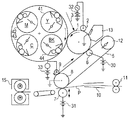
도 1은 본 발명에 따른 전자 사진 장치의 설명도이다.
도 2는 본 발명에 따른 전자 사진용 엔드리스 벨트의 제조에 사용하는 연신 블로우 성형기의 개략도이다.1 is an explanatory diagram of an electrophotographic apparatus according to the present invention.
2 is a schematic view of a stretch blow molding machine used for manufacturing an endless belt for electrophotography according to the present invention.
이하, 본 발명의 적합한 실시 형태에 대하여 상세하게 설명한다.Hereinafter, a preferred embodiment of the present invention will be described in detail.
본 발명자는, 상기의 목적을 감안하여, 균일한 막 두께의 내표면층을 구비한 전자 사진용 엔드리스 벨트를 보다 효율적으로 제조하는 방법에 대하여 검토하였다. 그 과정에 있어서, 본 발명자는, 프리폼의 내표면에 미경화의 에너지 경화성 수지를 도포한 후에 블로우 성형을 행하는 것을 검토하였다.The present inventors have considered a method for more efficiently producing an endless belt for electrophotography having an inner surface layer of uniform thickness in view of the above object. In the process, the present inventors studied blow molding after applying an uncured energy-curable resin to the inner surface of the preform.
그 결과, 미경화의 에너지 경화성 수지는 통상 단량체 또는 올리고머를 포함하는 액체이기 때문에, 블로우 성형 시에 연신 막대나 프리폼 유지 부재에 미경화의 에너지 경화성 수지가 부착되는 경우가 있었다.As a result, since the uncured energy curable resin is usually a liquid containing a monomer or an oligomer, an uncured energy curable resin sometimes adheres to the drawn rod or preform holding member during blow molding.
따라서 프리폼의 내표면에 도포한 에너지 경화성 수지를 경화시킨 후에 블로우 성형하는 것을 시도하였다. 그러나, 중합체화에 의한 경화가 불충분한 경우에는 여전히 연신 막대나 프리폼 유지 부재에 미경화의 에너지 경화성 수지가 부착되는 경우가 있었다. 한편, 완전히 경화시켜서 프리폼의 내표면에 경화막을 형성시킨 경우, 블로우 성형에 의한 프리폼의 팽창에 경화막이 추종할 수 없어서, 경화막에 크랙이 발생하는 경우가 있었다.Therefore, an attempt was made to blow-mold after curing the energy-curable resin applied to the inner surface of the preform. However, in the case where the curing by polymerization is insufficient, an uncured energy curable resin sometimes adheres to the stretching rod or the preform holding member. On the other hand, when the cured film is formed on the inner surface of the preform by completely curing, the cured film can not follow the expansion of the preform by blow molding, and cracks are sometimes generated in the cured film.
그로 인해, 내표면층을 갖는 전자 사진용 엔드리스 벨트를 효율적이고, 또한, 안정적으로 제조하기 위해서는, 새로운 제조 방법이 필요하다는 인식을 얻었다.Therefore, it has been recognized that a new manufacturing method is necessary to efficiently and stably manufacture an electrophotographic endless belt having an inner surface layer.
따라서, 본 발명자는, 프리폼의 내표면에 유리 전이 온도를 갖는 에너지 경화성 피막을 형성하고, 계속해서, 그 프리폼을 블로우 성형하여 블로우 보틀을 성형하고, 그 후에, 그 피막을 경화시키는 방법을 검토하였다. 그 결과, 이 방법에 의하면, 연신 막대나 프리폼 유지 부재를 오염시키지 않고 내표면층을 갖는 전자 사진용 엔드리스 벨트를 제조할 수 있는 것을 발견하였다.Therefore, the present inventors have studied a method of forming an energy-curable coating film having a glass transition temperature on the inner surface of a preform, subsequently blow-forming the preform to form a blow bottle, and then curing the coating film . As a result, it has been found that this method makes it possible to manufacture an endless belt for electrophotography having an inner surface layer without contaminating the stretching rod or the preform holding member.
<열가소성 수지 조성물>≪ Thermoplastic resin composition &
기층에 사용되는 열가소성 수지 조성물로서는, 시험관 형상의 프리폼으로부터 블로우 성형이 가능한 것이라면, 어떤 재료의 조합도 적절하게 사용할 수 있다. 주성분인 열가소성 수지로서는, 특히, 폴리프로필렌(PP), 폴리에틸렌(PE), 폴리아미드(PA), 폴리락트산(PLLA), 폴리에틸렌테레프탈레이트(PET), 폴리에틸렌나프탈레이트(PEN), 폴리페닐렌술피드(PPS), 불소 수지(PVdF 등) 등의 모든 열가소성 수지, 및 그 블렌드 수지도 사용에 적합하다. 열가소성 수지 조성물을 구성하는 다른 성분으로는, 이온 도전제(예를 들어, 고분자 이온계 도전제, 계면 활성제), 도전성 고분자, 산화 방지제(예를 들어, 힌더드 페놀계, 인, 황계), 자외선 흡수제, 유기 안료, 무기 안료, pH 조정제, 가교제, 상용화제, 이형제(예를 들어, 실리콘계, 불소계), 가교제, 커플링제, 활제, 절연성 필러(예를 들어 산화아연, 황산바륨, 황산칼슘, 티타늄산바륨, 티타늄산칼륨, 티타늄산스트론튬, 산화티타늄, 산화마그네슘, 수산화마그네슘, 수산화알루미늄, 탈크, 마이카, 클레이, 카올린, 하이드로탈사이트, 실리카, 알루미나, 페라이트, 탄산칼슘, 탄산바륨, 탄산 니켈, 유리 분말, 석영 분말, 유리 섬유, 알루미나 섬유, 티타늄산칼륨 섬유, 열경화성 수지의 미립자), 도전성 필러(예를 들어, 카본 블랙, 탄소 섬유, 도전성 산화티타늄, 도전성 산화주석, 도전성 마이카), 이온성 액체를 예시할 수 있다. 이들을 단독으로, 또는 2종류 이상 조합하여 사용하는 것도 가능하다.As the thermoplastic resin composition for use in the base layer, any combination of materials can be suitably used as long as it is capable of blow molding from a test tube-like preform. As the thermoplastic resin as the main component, a thermoplastic resin such as a polypropylene (PP), a polyethylene (PE), a polyamide (PA), a polylactic acid (PLLA), a polyethylene terephthalate (PET), a polyethylene naphthalate PPS), fluorine resin (PVdF and the like), and blend resins thereof are also suitable for use. Examples of other components constituting the thermoplastic resin composition include ionic conductive agents (for example, polymeric ion conductive agents and surfactants), conductive polymers, antioxidants (for example, hindered phenol-based, phosphorous, and sulfur-based) (For example, zinc oxide, barium sulfate, calcium sulfate, titanium oxide, and the like), an organic pigment, an inorganic pigment, a pH adjuster, a cross-linking agent, a compatibilizing agent, a releasing agent Magnesium hydroxide, talc, mica, clay, kaolin, hydrotalcite, silica, alumina, ferrite, calcium carbonate, barium carbonate, nickel carbonate, titanium oxide, strontium titanate, strontium titanate, titanium oxide, magnesium oxide, magnesium hydroxide, (E.g., glass powder, quartz powder, glass fiber, alumina fiber, potassium titanate fiber, fine particles of thermosetting resin), conductive fillers (e.g., carbon black, carbon fiber, , Conductive tin oxide, conductive mica), and an ionic liquid. These may be used singly or in combination of two or more kinds.
<에너지 경화성 피막>≪ Energy hardenable coating film &
본 발명에 관한, 프리폼의 내표면에 형성하는 에너지 경화성 피막은, 유리 전이 온도를 가질 필요가 있다. 즉, 유리 전이 온도를 갖는 에너지 경화성 피막은, 가교 전의 상태여도 수지화가 진행되고 있기 때문에, 연신 막대와 접촉한 경우에도, 연신 막대를 오염시키기 어렵다.The energy-curable coating formed on the inner surface of the preform according to the present invention needs to have a glass transition temperature. That is, even when the energy-curable coating film having a glass transition temperature is in a state of resin before crosslinking, even if it comes into contact with the stretching bar, it is difficult to contaminate the stretching bar.
이러한 피막을 프리폼의 내표면에 형성하는 방법으로는, 유리 전이 온도를 갖는 에너지 경화성 수지와 용매를 포함하는 수지 용액을 도포한 후에 용매를 휘발시켜서 도막을 형성시키는 방법이 일반적으로 사용된다.As a method for forming such a coating on the inner surface of the preform, a method of applying a resin solution containing an energy curable resin having a glass transition temperature and a solvent and then volatilizing the solvent to form a coating film is generally used.
유리 전이 온도를 갖지 않을 경우, 상기 수지 용액으로부터 용매를 휘발시켜도, 에너지 경화성 수지가 액체로서 존재하여, 피막을 형성할 수 없다. 그 때문에 블로우 성형 시에 연신 막대나 프리폼 유지 부재에 에너지 경화성 수지가 부착되는 경우가 있다.When the solvent does not have a glass transition temperature, even when the solvent is volatilized from the resin solution, the energy-curable resin exists as a liquid and a film can not be formed. Therefore, the energy-setting resin sometimes adheres to the stretching rod or the preform holding member during blow molding.
에너지 경화성 피막이 유리 전이 온도를 갖는 것은, 예를 들어, 피막의 점탄성(레올로지) 특성에 따른 피크의 관측이나 DSC(시차 열량 주사) 측정에 의해 얻어지는 DSC 커브의 변곡점 유무에 의해 알 수 있다.The fact that the energy-curable coating film has a glass transition temperature can be found, for example, by observing peaks depending on the viscoelasticity (rheology) characteristics of the coating film or by determining the inflection point of the DSC curve obtained by DSC (differential thermal analysis) measurement.
에너지 경화성 수지를 경화시키는 에너지로서는, 예를 들어, 광이나 방사선, 열을 들 수 있다. 상기 에너지 경화성 수지에 있어서 중합 개시종을 발생시킬 수 있는 에너지를 부여할 수 있는 활성 방사선이라면, 특별히 제한은 없고, 넓게 α선, γ선, X선, 자외선(UV), 가시광선, 전자선 등을 포함하는 것이다. 그 중에서도, 경화 감도 및 장치의 입수 용이성의 관점에서 자외선 및 전자선이 바람직하고, 특히 자외선이 바람직하다.The energy for curing the energy-curable resin may be, for example, light, radiation, or heat. There are no particular restrictions on the actinic radiation capable of imparting energy capable of generating polymerization initiating species to the energy-curable resin, and it is not particularly limited and can be broadly classified into? -Ray,? -Ray, X-ray, ultraviolet (UV), visible light, . Among them, ultraviolet rays and electron rays are preferable from the viewpoints of curing sensitivity and ease of obtaining the apparatus, and ultraviolet rays are particularly preferable.
사용하는 에너지 경화성 수지는 유리 전이 온도를 갖는 피막을 형성할 수 있는 물성을 가질 필요가 있다. 유리 전이 온도를 가지는지 여부는 일반적으로는 상기 수지의 분자량에 의해 어느 정도 결정할 수 있다.The energy-curable resin to be used needs to have physical properties capable of forming a film having a glass transition temperature. Whether or not the resin has a glass transition temperature can be determined to some extent by the molecular weight of the resin in general.
사용하는 에너지 경화성 수지는 용매에 용해시킬 필요가 있고, 적합한 용매는, 휘발성의 관점에서 유기 용매가 바람직하고, 예를 들어, 메틸에틸케톤이나 톨루엔, 메틸이소부틸케톤이 바람직하다. 이들을 단독으로, 또는 2종류 이상 조합하여 사용하는 것도 가능하다. 에너지 경화성 수지와 유기 용매의 질량비는 프리폼에 균일하게 피막이 형성된다면 특별히 제한은 없지만, 에너지 경화성 수지와 유기 용매의 질량비가 3:97 내지 90:10이 되는 것이 바람직하다.The energy curable resin to be used needs to be dissolved in a solvent. As a suitable solvent, an organic solvent is preferable from the viewpoint of volatility, and for example, methyl ethyl ketone, toluene and methyl isobutyl ketone are preferable. These may be used singly or in combination of two or more kinds. The mass ratio of the energy curable resin and the organic solvent is not particularly limited as long as the coating is uniformly formed on the preform, but it is preferable that the mass ratio of the energy curable resin and the organic solvent is 3:97 to 90:10.
사용하는 에너지 경화성 수지로서는, 아크릴기, 비닐기, 에폭시기 등의 중합성 관능기를 갖고 있는 것이 적합하다. 에너지 경화성 수지 중에서도, 경화 장치의 간편함 등의 관점에서, 자외선 경화성 아크릴 수지가 바람직하다. 또한 이들을 단독으로, 또는 2종류 이상 조합하여 사용하는 것도 가능하다.As the energy-curable resin to be used, those having a polymerizable functional group such as an acryl group, a vinyl group, and an epoxy group are preferable. Of the energy curable resins, ultraviolet curable acrylic resins are preferable from the viewpoints of simplicity of a curing apparatus and the like. It is also possible to use these alone or in combination of two or more.
즉, 본 발명에 따른 피막의 형성에 사용하는 수지로서는, 상기한 바와 같이, 아크릴기, 비닐기, 에폭시기 등의 중합성 관능기를 갖고, 프리폼을 용해하지 않는 용매에 대한 가용성을 구비하고 있고, 또한, 유리 전이 온도를 가질 필요가 있다.That is, as described above, the resin used for forming the coating film according to the present invention has a polymerizable functional group such as an acrylic group, a vinyl group, and an epoxy group and has solubility in a solvent that does not dissolve the preform, , It is necessary to have a glass transition temperature.
또한, 본 발명에 관한, 유리 전이 온도를 갖는 피막은, 프리폼을 블로우 성형함으로써 형성되는 블로우 보틀의 표면에 있어서도, 크랙을 발생하지 않고 피막으로서 존재할 필요가 있다. 즉, 그 피막은, 블로우 성형에 의한 프리폼의 신전에 충분히 추종 가능할 만큼의 유연성을 가질 필요가 있다.The coating film having a glass transition temperature according to the present invention should also be present as a film without causing cracks on the surface of the blow bottle formed by blow molding the preform. That is, the film needs to have flexibility enough to follow the extension of the preform by blow molding.
피막에 이러한 유연성을 부여하기 위해서는, 피막의 형성에 사용하는, 유리 전이 온도를 갖는 수지의 중량 평균 분자량을 적절히 선택하는 것이 바람직하다.In order to impart such flexibility to the coating, it is preferable to appropriately select the weight average molecular weight of the resin having a glass transition temperature used for forming the coating film.
예를 들어, 프리폼을 블로우 성형하고, 외경이 프리폼 외경의 4.5배인 블로우 보틀을 성형하는 경우에 있어서는, 그 프리폼의 내표면에 형성하는 유리 전이 온도를 갖는 피막의 형성에 사용하는 수지로서는, 「유니딕 RC29-129」(상품명, DIC 가부시끼가이샤 제조, 중량 평균 분자량=30000)나, 「아크리트 KX-012C」(상품명, 다이세이 파인케미컬 가부시끼가이샤 제조, 중량 평균 분자량=25000) 등을 사용할 수 있다.For example, in the case of blow molding a preform and molding a blow bottle having an outer diameter of 4.5 times the outer diameter of the preform, as a resin used for forming a film having a glass transition temperature formed on the inner surface of the preform, Dic RC29-129 "(trade name, manufactured by DIC Corporation, weight average molecular weight = 30000) and" Acryt KX-012C "(trade name, manufactured by Daicel Chemical Industries, Ltd., weight average molecular weight = 25000) .
그리고, 프리폼의 외경에 대한 블로우 보틀의 외경 비율을, 보다 크게 하는 경우에 있어서는, 아크릴기, 비닐기, 에폭시기 등의 중합성 관능기를 갖고, 프리폼을 용해하지 않는 용매에 대한 가용성을 구비하고 있고, 또한, 유리 전이 온도를 갖고 있다고 하는 제한의 범위 내에 있어서, 피막에 블로우 성형 시의 프리폼의 팽창에 충분히 추종성을 부여하기 위해서는, 중량 평균 분자량을 조금 낮게 조정하는 것이 바람직하다.When the ratio of the outer diameter of the blow bottle to the outer diameter of the preform is made larger, it has a solubility in a solvent having a polymerizable functional group such as an acrylic group, a vinyl group or an epoxy group, Also, within the limit of the glass transition temperature, it is preferable to adjust the weight average molecular weight to a slightly low value in order to give the film sufficiently followability to the expansion of the preform during blow molding.
에너지 경화성 수지의 피막을 구성하는 성분으로서는 에너지 경화성 수지 이외에 여러가지의 첨가제를 포함하고 있어도 되고, 예를 들어, 중합 개시제, 이온 도전제(예를 들어, 고분자 이온계 도전제, 계면 활성제), 도전성 고분자, 산화 방지제(예를 들어, 힌더드 페놀계, 인, 황계), 자외선 흡수제, 유기 안료, 무기 안료, pH 조정제, 가교제, 상용화제, 이형제(예를 들어, 실리콘계, 불소계), 가교제, 커플링제, 활제, 절연성 필러(예를 들어 산화아연, 황산바륨, 황산칼슘, 티타늄산바륨, 티타늄산칼륨, 티타늄산스트론튬, 산화티타늄, 산화마그네슘, 수산화마그네슘, 수산화알루미늄, 탈크, 마이카, 클레이, 카올린, 하이드로탈사이트, 실리카, 알루미나, 페라이트, 탄산칼슘, 탄산바륨, 탄산 니켈, 유리 분말, 석영 분말, 유리 섬유, 알루미나 섬유, 티타늄산칼륨 섬유, 열경화성 수지의 미립자), 도전성 필러(예를 들어, 카본 블랙, 탄소 섬유, 도전성 산화티타늄, 도전성 산화주석, 도전성 산화아연, 도전성 마이카, 안티몬산 아연), 이온성 액체를 예시할 수 있다. 이들을 단독으로, 또는 2종류 이상 조합하여 사용하는 것도 가능하다.The components constituting the film of the energy-curable resin may contain various additives in addition to the energy-curable resin, and examples thereof include a polymerization initiator, an ionic conductive agent (for example, a polymeric ionic conductive agent, a surfactant) An organic pigment, an inorganic pigment, a pH adjuster, a crosslinking agent, a compatibilizing agent, a releasing agent (for example, a silicone type, a fluorine type), a crosslinking agent, a coupling agent , Barium titanate, titanium oxide, titanium oxide, magnesium oxide, magnesium hydroxide, aluminum hydroxide, talc, mica, clay, kaolin, kaolin, and other fillers such as zinc oxide, barium sulfate, calcium sulfate, barium titanate, Hydrotalcite, silica, alumina, ferrite, calcium carbonate, barium carbonate, nickel carbonate, glass powder, quartz powder, glass fiber, alumina fiber, Fine particles of fiber, thermosetting resin), an electrically conductive filler (e.g., carbon black, there can be mentioned a carbon fiber, conductive titanium oxide, conductive tin oxide, conductive zinc oxide, conductive mica, antimony acid zinc), the ionic liquid. These may be used singly or in combination of two or more kinds.
<전자 사진용 엔드리스 벨트의 제조 방법>≪ Manufacturing method of endless belt for electrophotography >
본 발명에 따른 전자 사진용 엔드리스 벨트의 제조 방법은 3개의 공정을 갖는 것을 특징으로 한다. 즉,The method for manufacturing an endless belt for electrophotography according to the present invention is characterized by having three processes. In other words,
(1) 열가소성 수지를 포함하는, 시험관 형상의 프리폼의 내표면에 유리 전이 온도를 갖는 에너지 경화성 피막을 형성하고, 계속해서, 그 프리폼을 블로우 성형하여 블로우 보틀을 얻는 공정과,(1) a step of forming an energy-curable coating film having a glass transition temperature on the inner surface of a test tube-like preform including a thermoplastic resin, and subsequently blow-molding the preform to obtain a blow-
(2) 그 블로우 보틀에 에너지선을 조사하여 상기 피막을 경화시켜서 내표면층을 형성하는 공정과,(2) a step of irradiating an energy ray to the blow bottle to cure the coating to form an inner surface layer,
(3) 공정 (2)에 의해 얻은 내표면층을 갖는 블로우 보틀로부터 엔드리스 벨트를 잘라내는 공정을 갖는 것을 특징으로 하고 있는 제조 방법이다.(3) a step of cutting off the endless belt from the blow bottle having the inner surface layer obtained in the step (2).
열가소성 수지를 포함하는, 시험관 형상의 프리폼을 제작하는 방법으로서는, 사출 성형에 의한 방법이 일반적이고, 후술하는 2축 연신이 가능할 정도로 비정질의 상태를 가질 필요가 있다. 이러한 프리폼은 열가소성 수지 조성물을 프리폼 형상의 금형 내에 넣어서 사출 성형에 의해 제조할 때의 금형 온도를 조정함으로써 얻을 수 있다.As a method of producing a test tube-like preform including a thermoplastic resin, a method by injection molding is generally used, and it is necessary to have an amorphous state to such an extent that biaxial stretching which will be described later is possible. Such a preform can be obtained by adjusting the temperature of the mold when the thermoplastic resin composition is put into a preform-shaped mold and produced by injection molding.
구체적으로는, 금형 온도를 열가소성 수지 조성물의 유리 전이 온도보다 충분히 낮은 온도로 설정하여 금형 내에서 열가소성 수지 조성물을 급냉시킨다. 2축 연신 가능할 정도로 비정질의 상태의 프리폼을 얻는 관점에서, 사출 성형의 실린더 온도는 열가소성 수지 조성물의 융점보다 20 내지 50℃ 정도 높은 온도로 설정하는 것이 바람직하고, 금형 온도로서는 열가소성 수지 조성물의 유리 전이 온도보다 20 내지 100℃ 정도 낮은 온도로 설정하는 것이 바람직하다.Specifically, the mold temperature is set to a temperature sufficiently lower than the glass transition temperature of the thermoplastic resin composition, and the thermoplastic resin composition is quenched in the mold. From the viewpoint of obtaining a preform in an amorphous state to such an extent that biaxial stretching is possible, the cylinder temperature of the injection molding is preferably set to a temperature higher by about 20 to 50 DEG C than the melting point of the thermoplastic resin composition, and the glass transition temperature of the thermoplastic resin composition It is preferable to set the temperature to about 20 to 100 DEG C lower than the temperature.
다음으로 유리 전이 온도를 갖는 에너지 경화성 피막 형성 방법에 대하여 설명한다. 유기 용매 등에 용해된 유리 전이 온도를 갖는 에너지 경화성 수지 용액을 공지된 방법으로 프리폼의 내표면에 도포한 뒤, 유기 용매를 휘발시키기 위하여 항온조 등에 방치시키는 것이 일반적이다. 프리폼의 내표면에의 도포 방법으로서는, 예를 들어, 스프레이 도포나 디핑 도포를 들 수 있는데, 간편함의 관점에서 디핑 도포가 바람직하다.Next, a method of forming an energy-curable coating film having a glass transition temperature will be described. An energy curable resin solution having a glass transition temperature dissolved in an organic solvent or the like is applied to the inner surface of a preform by a known method and then left in a thermostat or the like for volatilizing the organic solvent. As a coating method on the inner surface of the preform, for example, spray application or dipping application can be mentioned, and dipping application is preferable from the viewpoint of simplicity.
상기 에너지 경화성 피막을 내표면에 형성한 프리폼의 블로우 성형 방법에 대하여 설명한다.A blow molding method of a preform having the energy-curable coating formed on its inner surface will be described.
프리폼에 피막을 도포하는 관점에서 콜드 패리슨법에 의한 블로우 성형이 바람직하다. 콜드 패리슨법이란 사출 성형법에 의해 얻어진 프리폼의 배럴 벽부를 주로 재가열하고, 프리폼을 구성하는 열가소성 수지 조성물의 유리 전이 온도 이상 융점 이하에서 블로우용 금형 내에서 연신 막대를 사용하여 프리폼을 그 축방향으로 연신시킴과 함께, 그 프리폼의 내부에 기체를 불어 넣어서 직경 방향으로 연신시켜 블로우 보틀을 얻는 방법이다.Blow molding by the cold parison method is preferable from the viewpoint of applying the coating to the preform. The cold parison method is a method in which the barrel wall portion of the preform obtained by the injection molding method is mainly reheated and the preform is heated in the axial direction by using an elongating rod in the blow mold at a temperature equal to or higher than the glass transition temperature of the thermoplastic resin composition constituting the preform And then drawing the preform in a radial direction by blowing a gas into the preform, thereby obtaining a blow bottle.
본 발명에 의한 방법에서는 에너지 경화성 수지가 피막으로서 형성되어 있기 때문에, 블로우 성형해도 연신 막대나 프리폼 유지 부재에 그 수지가 붙거나 하는 것에 의한 장치 오염이 발생하지 않는다. 또한 프리폼을 폭을 넓혀서 보틀로 성형하기 위해서, 내표면의 피막 두께를 두껍게 할 필요가 있고, 종래의 피막에서는 액이 축 늘어져서, 두께 불균일이 커지는 현상이 보여졌지만, 유리 전이 온도를 갖는 에너지 경화성 피막 경우, 충분한 액점도를 확보할 수 있기 때문에, 피막을 두껍게 해도, 두께 불균일을 적게 유지할 수 있다.In the method according to the present invention, since the energy-curable resin is formed as a coating film, the resin does not adhere to the stretching rod or the preform holding member even if the resin is blow molded. Further, in order to form the preform into a bottle by expanding its width, it is necessary to increase the thickness of the coating on the inner surface, and in the conventional coating, the phenomenon that the liquid becomes axially stretched and the thickness irregularity becomes large. , A sufficient liquid viscosity can be ensured, so that even if the coating film is made thick, the thickness irregularity can be kept small.
상기의 방법에 의해 얻어진 블로우 보틀에 추종하는 형으로 에너지 경화성 피막을 형성할 수 있다. 그 블로우 보틀을 절단하거나 하여, 보틀의 내표면에 에너지를 조사함으로써 에너지 경화성 피막을 경화할 수 있다.An energy-curable coating film can be formed as a mold following the blow-up bottle obtained by the above method. And the energy ray-curable coating can be cured by irradiating energy to the inner surface of the bottle by cutting the blow bottle.
또한 공지된 방법을 사용하여, 형상을 제어하기 위해서, 블로우 보틀을 전주에 씌우고, 블로우 보틀에 에어 등의 압력을 인가하면서, 블로우 보틀을 구성하는 열가소성 수지 조성물의 유리 전이 온도 이상으로 가열 후, 상온, 상압까지 복귀시키고, 블로우 보틀을 취출한다는 공정 등을 첨가해도 된다.Further, in order to control the shape using a known method, a blow bottle is placed on a pole and heated to a temperature not lower than the glass transition temperature of the thermoplastic resin composition constituting the blow bottle while applying pressure such as air to the blow bottle, , Returning to the atmospheric pressure, and taking out the blow bottle.
상기의 방법에 의해 얻어진 내표면층을 갖는 블로우 보틀로부터 동체 부분을 소정의 폭으로 절단한 후에 동체 부분의 내표면에 에너지를 조사함으로써, 본 발명에 따른 전자 사진용 엔드리스 벨트를 얻을 수 있다.The endless belt for electrophotography according to the present invention can be obtained by irradiating energy to the inner surface of the moving body portion after cutting the moving body portion to a predetermined width from the blow bottle having the inner surface layer obtained by the above method.
전자 사진용 엔드리스 벨트의 기층의 두께로서는, 10㎛ 이상 500㎛ 이하, 특히는, 30㎛ 이상 150㎛ 이하가 일반적이다. 또한 전자 사진용 엔드리스 벨트의 기층의 구체적인 체적 고유 저항률의 목표로서는, 전자 사진용 엔드리스 벨트를 중간 전사 벨트로서 사용하는 경우에는, 1×10²Ωcm 이상 1×10¹⁴Ωcm 이하이다.The thickness of the base layer of the electrophotographic endless belt is generally from 10 탆 to 500 탆, particularly from 30 탆 to 150 탆. The specific volume resistivity of the base layer of the electrophotographic endless belt is preferably 1 x 10 2 ? Cm or more and 1 x 10 14 ? Cm or less when the electrophotographic endless belt is used as the intermediate transfer belt.
전자 사진용 엔드리스 벨트의 내표면층의 두께로서는, 0.05㎛ 이상 10㎛ 이하, 특히, 0.2㎛ 이상 5㎛ 이하가 일반적이다. 또한 전자 사진용 엔드리스 벨트의 표면층의 구체적인 표면 고유 저항률의 목표로서는, 전자 사진용 엔드리스 벨트를 중간 전사 벨트로서 사용하는 경우에는, 1×10²Ω/sq 이상, 1×10¹⁴Ω/sq 이하이다.The thickness of the inner surface layer of the endless belt for electrophotography is generally from 0.05 탆 to 10 탆, particularly from 0.2 탆 to 5 탆. The specific surface resistivity of the surface layer of the electrophotographic endless belt is preferably 1 x 10 2 ? / Sq or more and 1 x 10 14 ? / Sq or less when the electrophotographic endless belt is used as the intermediate transfer belt .
전자 사진용 엔드리스 벨트의 내표면층의 표면 고유 저항률을 1×10⁴Ω/sq 이상, 1×10⁸Ω/sq 이하로 하고, 벨트의 둘레 방향으로 전류를 통하기 쉽게 함으로써, 일본 특허 공개 제2012-137733에 기재되어 있는 1차 전사용의 전류 공급 부재를 없앤 저비용으로 소형화가 가능한 전자 사진 장치를 제공하는 것이 가능하게 된다.The surface resistivity of the inner surface layer of the electrophotographic endless belt is set to 1 × 10 4 Ω / sq or more and 1 × 10 8 Ω / sq or less so that current can be passed in the circumferential direction of the belt, It is possible to provide an electrophotographic apparatus which can reduce the size and cost by eliminating the current supplying member for primary transfer described in JP-A-137733.
전자 사진용 엔드리스 벨트의 내표면층의 경도로서는, 이물이나 블로빙(blobbing)에 의한 요철 발생의 방지의 관점에서 연필 경도로 H 이상이 바람직하고, 내구 굴곡 피로에 의한 크랙 발생의 억제의 관점에서 3H 이하인 것이 바람직하다.The hardness of the inner surface layer of the endless belt for electrophotography is preferably not less than H in terms of pencil hardness from the viewpoint of prevention of occurrence of unevenness due to foreign matters or blobbing, Or less.
또한, 전자 사진용 엔드리스 벨트의 내표면층의 신장률(인장 신도)로서는, 내구 굴곡 피로에 의한 크랙 발생의 방지의 관점에서 3% 이상인 것이 바람직하다. 그리고, 본 발명에 관한, 유리 전이 온도를 갖는 에너지 경화성 피막 경화막을 포함하는 내표면층을 기층의 내주면 측에 형성하여 이루어지는 전자 사진용 엔드리스 벨트는, 내표면층이 우수한 유연성을 나타내어, 상기한 신장률을 잘 달성할 수 있다. 그로 인해, 장기간에 걸쳐 롤러 간에 걸쳐져 사용된 경우에도 표면층의 기층으로부터의 박리 등이 발생하기 어려운 내구성이 우수한 전자 사진용 엔드리스 벨트가 된다.The elongation percentage (tensile elongation) of the inner surface layer of the endless belt for electrophotography is preferably 3% or more from the viewpoint of prevention of cracking due to endurance bending fatigue. The electrophotographic endless belt according to the present invention comprising an inner surface layer including an energy-curable film hardening film having a glass transition temperature on the inner circumferential surface side of a base layer is characterized in that the inner surface layer exhibits excellent flexibility, Can be achieved. Therefore, even when the roller is used over a long period of time between rollers, the endless belt for electrophotography has excellent durability in which peeling of the surface layer from the base layer hardly occurs.
<전자 사진 장치><Electrophotographic apparatus>
본 발명에 따른 전자 사진 장치에 대하여 설명한다. 도 1은 풀컬러 전자 사진 장치의 단면도이다. 도 1 중, 중간 전사 벨트(5)로서 본 발명에 따른 원통 형상의 전자 사진용 엔드리스 벨트를 사용하고 있다. 전자 사진 감광체(1)는 제1 화상 담지체로서 반복 사용되는 회전 드럼형의 전자 사진 감광체(이하, 「감광 드럼」이라고 기재함)이며, 화살표 방향으로 소정의 주속도(프로세스 스피드)를 갖고 회전 구동된다. 감광 드럼(1)은 회전 과정에서, 1차 대전기(2)에 의해 소정의 극성·전위로 균일하게 대전 처리된다. 계속하여 노광 수단에 의한 화상 노광(3)을 받음으로써 목적으로 하는 컬러 화상의 제1색 성분상(예를 들어, 옐로우색 성분상)에 대응한 정전 잠상이 형성된다.An electrophotographic apparatus according to the present invention will be described. 1 is a cross-sectional view of a full-color electrophotographic apparatus. 1, a cylindrical electrophotographic endless belt according to the present invention is used as the
또한, 상기 노광 수단으로서는, 컬러 원고 화상의 색 분해·결상 노광 광학계, 화상 정보의 시계열 전기 디지털 화소 신호에 대응하여 변조된 레이저 빔을 출력하는 레이저 스캐너에 의한 주사 노광계 등을 들 수 있다. 계속해서, 그 정전 잠상이 제1 현상기(옐로우색 현상기(41))에 의해 제1색인 옐로우 토너 Y에 의해 현상된다. 이때 제2 내지 제4 현상기(마젠타색 현상기(42), 시안색 현상기(43), 블랙색 현상기(44))의 각 현상기는 작동이 오프로 되어 있어서 감광 드럼(1)에는 작용하지 않아, 상기 제1색의 옐로우 토너 화상은 상기 제2 내지 제4 현상기에 의해 영향을 받지 않는다.The exposure means includes a color separation and image formation optical system for a color original image, and a scanning exposure system using a laser scanner for outputting a modulated laser beam corresponding to a time-series electrical digital pixel signal of image information. Subsequently, the electrostatic latent image is developed by the first developing unit (yellow developing unit 41) by the yellow toner Y of the first color. At this time, the respective developing devices of the second to fourth developing devices (magenta developing device 42, cyan developing device 43, and black developing device 44) are turned off and do not act on the photosensitive drum 1, The yellow toner image of the first color is not affected by the second to fourth developing units.
전자 사진용 벨트(5)는 화살표 방향으로 감광 드럼(1)과 동일한 주속도를 갖고 회전 구동되고 있다. 감광 드럼(1) 상의 옐로우 토너 화상은, 감광 드럼(1)과 중간 전사 벨트(5)의 닙부를 통과 시에, 대향 롤러(6)로부터 전자 사진용 벨트(5)에 인가되는 1차 전사 바이어스에 의해 형성되는 전계에 의해, 중간 전사 벨트(5)의 외주면에 전사된다(1차 전사). 전자 사진용 벨트(5)에 제1색의 옐로우 토너 화상의 전사를 종료한 감광 드럼(1)의 표면은, 클리닝 장치(13)에 의해 청소된다. 이하, 동일하게 제2색의 마젠타 토너 화상, 제3색의 시안 토너 화상, 제4색의 블랙 토너 화상이 순차 전자 사진용(중간 전사) 벨트(5) 상에 중첩하여 전사되어, 원하는 컬러 화상에 대응한 합성 컬러 토너 화상이 형성된다. 2차 전사 롤러(7)는 구동 롤러(8)에 대응하여 평행하게 축받이시켜서 전자 사진용 벨트(5)의 하면부에 이격 가능한 상태로 배치되어 있다.The
감광 드럼(1)으로부터 전자 사진용 벨트(5)에의 제1 내지 제3색의 토너 화상의 1차 전사 공정 시에, 2차 전사 롤러(7)는 전자 사진용 벨트(5)로부터 이격하는 것도 가능하다. 전자 사진용 벨트(5) 상에 전사된 합성 컬러 토너 화상의 제2 화상 담지체인 전사재 P에의 전사는 다음과 같이 행하여진다.During the primary transferring process of the toner images of the first to third colors from the photosensitive drum 1 to the
먼저, 2차 전사 롤러(7)가 전자 사진용 벨트(5)에 접촉됨과 함께, 급지 롤러(11)로부터 전사재 가이드(10)를 통하여, 전자 사진용 벨트(5)와 2차 전사 롤러(7)의 접촉 닙에 소정의 타이밍으로 전사재 P가 급송된다.The secondary transfer roller 7 is first brought into contact with the
그리고, 2차 전사 바이어스가 전원(31)으로부터 2차 전사 롤러(7)에 인가된다. 이 2차 전사 바이어스에 의해 전자 사진용(중간 전사) 벨트(5)로부터 제2 화상 담지체인 전사재 P에 합성 컬러 토너 화상이 전사(2차 전사)된다. 토너 화상의 전사를 받은 전사재 P는 정착기(15)에 도입되어 가열 정착된다. 전사재 P에의 화상 전사 종료 후, 전자 사진용 벨트(5)에는 클리닝 장치의 중간 전사 벨트 클리닝 롤러(9)가 접촉되어, 감광 드럼(1)과는 역극성의 바이어스가 인가된다. 이에 의해, 전사재 P에 전사되지 않고 전자 사진용 벨트(5) 상에 잔류하고 있는 토너(전사 잔류 토너)에 감광 드럼(1)과 역극성의 전하가 부여된다. 33은 바이어스 전원이다. 상기 전사 잔류 토너는, 감광 드럼(1)과의 닙부 및 그 근방에 있어서 감광 드럼(1)에 정전적으로 전사됨으로써, 전자 사진용 벨트(5)가 클리닝된다.Then, the secondary transfer bias is applied from the power supply 31 to the secondary transfer roller 7. [ By this secondary transfer bias, the composite color toner image is transferred (secondary transfer) from the electrophotographic (intermediate transfer)
실시예Example
이하에 실시예 및 비교예를 나타내고, 본 발명을 구체적으로 설명한다. 또한, 실시예 및 비교예에서는 전자 사진용 벨트 중 전자 사진용 엔드리스 벨트를 제작하고, 실시예 및 비교예에 사용한 분석 및 물성의 측정은 이하와 같이 행하였다.EXAMPLES Hereinafter, the present invention will be described in detail with reference to Examples and Comparative Examples. In the Examples and Comparative Examples, an electrophotographic endless belt of an electrophotographic belt was produced, and analysis and physical properties used in Examples and Comparative Examples were measured as follows.
(특성값의 측정법, 평가법)(Measurement method of characteristic value, evaluation method)
실시예 및 비교예에서 제작한 전자 사진용 엔드리스 벨트의 특성값 측정 방법 및 평가 방법은 다음과 같다.The method of measuring and evaluating the characteristic values of the endless belt for electrophotography produced in Examples and Comparative Examples are as follows.
<에너지 경화성 수지 피막의 유리 전이 온도>≪ Glass Transition Temperature of Energy Curable Resin Coating >
판유리 상에 에너지 경화성 수지 용액을 도포한 후, 70℃의 건조로에서 10분간 방치한 후, 취출하고, 판유리 상으로부터 에너지 경화성 수지를 제거하였다. 이 수지를 10mg의 크기가 되도록 잘라내고, 시차 주사 열량 분석계(DSC, 상품명: DSC823, 메틀러 톨레도(주)제)를 사용하여, -30℃부터 200℃까지 10℃/min의 승온 속도로 측정하고, 그것에 의하여 얻어진 DSC 커브에 있어서의 유리 전이를 나타내는 변곡점의 중심 온도를 유리 전이 온도로 하였다. 유리 전이 온도가 관측되지 않는 것은 「없음」이라고 표 5에 명기하였다.The energy-curable resin solution was applied on a glass plate, then left in a drying furnace at 70 占 폚 for 10 minutes, removed, and the energy-curing resin was removed from the plate glass. The resin was cut to a size of 10 mg and measured from -30 ° C to 200 ° C at a heating rate of 10 ° C / min using a differential scanning calorimeter (DSC, trade name: DSC823, manufactured by Mettler Toledo K.K.) , And the center temperature of the inflection point indicating the glass transition in the DSC curve obtained thereby was defined as the glass transition temperature. &Quot; No " indicating that the glass transition temperature is not observed is specified in Table 5.
<프리폼의 내표면층의 두께 측정 방법>≪ Method of measuring thickness of inner surface layer of preform >
프리폼의 내표면층의 두께는 프리폼의 두께 단면을 초음파 커터로 절삭하고, 마이크로미터를 사용하여, 프리폼과 내표면층을 합한 두께로부터 프리폼의 두께를 뺌으로써 구하였다.The thickness of the inner surface layer of the preform was obtained by cutting the thickness section of the preform with an ultrasonic cutter and subtracting the thickness of the preform from the total thickness of the preform and the inner surface layer using a micrometer.
<전자 사진용 엔드리스 벨트의 내표면층의 두께 측정 방법>≪ Method of measuring thickness of inner surface layer of endless belt for electrophotography >
전자 사진용 엔드리스 벨트의 내표면층의 두께는 벨트의 두께 단면을 마이크로톰 등으로 절삭하고, 단면을 전계 방사 주사형 전자 현미경(FE-SEM)(상품명: XL30, FEI 테크놀로지(주)제)으로 관찰함으로써 산출하였다. 둘레 방향으로 균일한 거리로 3점, 축방향으로 균일한 거리로 2점의 계 6점의 위치에서의 엔드리스 벨트의 내표면층의 두께를 측정하고, 평균값과 최댓값과 최솟값을 구하였다.The thickness of the inner surface layer of the endless belt for electrophotography was measured by cutting a thickness section of the belt with a microtome or the like and observing the end face with an electrospinning scanning electron microscope (FE-SEM) (trade name: XL30, manufactured by FEI Technology Corporation) Respectively. The thickness of the inner surface layer of the endless belt was measured at three points at a uniform distance in the circumferential direction and six points at two points at a uniform distance in the axial direction, and the average value, the maximum value and the minimum value were obtained.
<전자 사진용 엔드리스 벨트의 내표면층의 경도>≪ Hardness of inner surface layer of electrophotographic endless belt >
전자 사진용 엔드리스 벨트의 내표면층의 경도는 ISO15184에 기재되어 있는 연필 경도의 측정 방법에 준하였다. 연필심의 경도(6B~HB~6H)의 사이에서 표기하고, 6B가 가장 부드럽고, 6H가 가장 단단한 것을 나타내고 있다. 벨트 둘레 방향의 줄무늬 발생 방지의 관점에서 연필 경도는 H 이상이 바람직하다고 생각된다.The hardness of the inner surface layer of the endless belt for electrophotography was measured in accordance with the method of measuring the pencil hardness described in ISO15184. Between the hardness of the pencil lead (6B to HB to 6H), 6B is the smoothest, and 6H is the hardest. From the viewpoint of prevention of streaking in the belt circumferential direction, it is considered that the pencil hardness is preferably H or more.
<전자 사진용 엔드리스 벨트의 내표면층의 신장률>≪ Elongation of inner surface layer of electrophotographic endless belt >
전자 사진용 엔드리스 벨트의 내표면층의 신장률은 ISO527-2에 기재되어 있는 인장 신도의 측정 방법에 준하였다. 벨트를 폭 10mm, 길이 50mm로 커트하고, 인장 시험 장치(상품명: 인스트론(5583), 인스트론(주)제)로 척간 거리 30mm, 1mm/min의 속도로 인장 시험을 행하였다. 벨트 내표면층의 크랙 또는 파단 발생 방지의 관점에서 인장 신도는 3% 이상이 바람직하다고 생각된다.The elongation percentage of the inner surface layer of the endless belt for electrophotography was measured in accordance with the measurement method of the tensile elongation described in ISO 527-2. The belt was cut into a width of 10 mm and a length of 50 mm and subjected to a tensile test at a speed of 1 mm / min at a chuck distance of 30 mm with a tensile tester (trade name: Instron (5583), manufactured by Instron). From the viewpoint of preventing cracks or fracture of the surface layer in the belt, the tensile elongation is preferably 3% or more.
<전자 사진용 엔드리스 벨트의 내표면 고유 저항률(ρs)><Intrinsic resistivity (? S) of the inner surface of the endless belt for electrophotography>
측정 장치는, 고저항계(상품명: 하이 레스타 UP MCP-HT450형, 미쯔비시 가가꾸 애널리틱(주)제)의 주전극의 내경이 50mm, 가드·링 전극의 내경이 5.9mm, 외경이 11.0mm인 프로브(상품명: UR-S, 미쯔비시 가가꾸 애널리틱(주)제)를 사용하여 JIS-K6911에 준거하는 형으로 측정하였다. 전압 100V를 10초간 벨트에 인가하고, 벨트의 내표면 둘레 방향으로 표면 고유 저항률을 4점 측정하고, 그 평균값을 채용하였다. 표면 고유 저항률이 108Ω/sq 이하가 되는 것은, 벨트의 둘레 방향으로 전류를 통하기 쉽게 함으로써, 일본 특허 공개 제2012-137733에 기재되어 있는 1차 전사용의 전류 공급 부재를 없앤 저비용으로 소형화가 가능한 전자 사진 장치를 제공하는 것이 가능하게 된다.The measurement device was a device having an inner diameter of a main electrode of a high resistance meter (trade name: Hiresta UP MCP-HT450 type, manufactured by Mitsubishi Chemical), an inner diameter of a guard ring electrode of 5.9 mm, an outer diameter of 11.0 mm (UR-S, manufactured by Mitsubishi Chemical Industry Co., Ltd.) in accordance with JIS-K6911. A voltage of 100 V was applied to the belt for 10 seconds, and the surface specific resistivity was measured at four points in the circumferential direction of the inner surface of the belt, and the average value was adopted. The fact that the surface resistivity is less than or equal to 10 8 Ω / sq makes it possible to conduct the current in the circumferential direction of the belt, thereby reducing the current supply member for primary transfer described in Japanese Patent Application Laid- It becomes possible to provide a possible electrophotographic apparatus.
<전자 사진용 엔드리스 벨트의 내구성 확인 방법 1>≪ Method for checking durability of an endless belt for electrophotography &
전자 사진용 엔드리스 벨트를 도 1에 도시된 바와 같은 장치 구조를 갖는 레이저 빔 프린터(상품명: LBP-5200, 캐논(주)제)의 중간 전사 유닛에 중간 전사 벨트로서 장착하였다. 150000매 종이 통과시킨 후에 온도 23℃, 50% RH의 환경 하에서, 155g/㎡의 A4 사이즈의 그로스지에 시안과 마젠타의 2색을 사용하여 보라색의 솔리드 화상을 프린트하였다. 이 화상을 육안으로 관찰하고, 엔드리스 벨트의 내구성에 기인하는 벨트 둘레 방향의 줄무늬 유무를 확인하고, 이하의 기준으로 평가하였다. 벨트 둘레 방향의 줄무늬는 이물이나 티끌에 의한 벨트 내표면에 의한 요철 발생이 원인이라고 생각된다.The electrophotographic endless belt was mounted as an intermediate transfer belt in an intermediate transfer unit of a laser beam printer (trade name: LBP-5200, manufactured by Canon Inc.) having a device structure as shown in Fig. After passing through 150000 sheets of paper, a solid image of purple was printed using two colors of cyan and magenta in an A4 size gauge paper of 155 g / m < 2 > under an environment of 23 DEG C and 50% RH. This image was observed with naked eyes and the presence or absence of streaking in the belt circumferential direction due to the durability of the endless belt was checked and evaluated based on the following criteria. It is considered that the stripe pattern in the belt circumferential direction is caused by the unevenness caused by the inner surface of the belt due to the foreign object or the dust.
A: 출력한 화상에 벨트 둘레 방향의 줄무늬가 없는 것A: Output image has no stripes in the circumferential direction of the belt
B: 출력한 화상에 벨트 둘레 방향의 줄무늬가 있는 것B: Streaks in the belt-circumferential direction of the printed image
<전자 사진용 엔드리스 벨트의 내구성 확인 방법 2>≪ Method for checking durability of endless belt for electrophotography &
전자 사진용 엔드리스 벨트를 도 1에 도시된 바와 같은 장치 구조를 갖는 레이저 빔 프린터(상품명: LBP-5200, 캐논(주)제)의 중간 전사 유닛에 중간 전사 벨트로서 장착하였다. 150000매 종이 통과시킨 후에 온도 23℃, 50% RH의 환경 하에서, 155g/㎡의 A4 사이즈의 그로스지에 시안과 마젠타의 2색을 사용하여 보라색의 솔리드 화상을 프린트하였다. 이 화상을 육안으로 관찰하고, 엔드리스 벨트의 내구성에 기인하는 벨트의 국소적인 농도 불균일 또는 방사상 또는 벨트 축방향의 줄무늬 유무를 확인하고, 이하의 기준으로 평가하였다. 벨트의 국소적인 농도 불균일 또는 방사상의 줄무늬, 벨트 축방향의 줄무늬는 벨트 내표면의 크랙 발생에 의한 것이라고 생각된다.The electrophotographic endless belt was mounted as an intermediate transfer belt in an intermediate transfer unit of a laser beam printer (trade name: LBP-5200, manufactured by Canon Inc.) having a device structure as shown in Fig. After passing through 150000 sheets of paper, a solid image of purple was printed using two colors of cyan and magenta in an A4 size gauge paper of 155 g / m < 2 > under an environment of 23 DEG C and 50% RH. This image was observed with naked eyes, and local irregularity of density of the belt due to durability of the endless belt or presence or absence of streaks in the radial direction or the belt axis direction was evaluated and evaluated according to the following criteria. It is considered that local irregularity of density of the belt, radial streaks, and stripe patterns in the belt axis direction are caused by cracks on the inner surface of the belt.
A: 출력한 화상에 국소적인 농도 불균일 또는 방사상의 줄무늬, 벨트 축방향의 줄무늬가 없는 것A: Output image has local density irregularities or radial streaks, and no streaks in the belt axis direction
B: 출력한 화상에 국소적인 농도 불균일 또는 방사상의 줄무늬, 벨트 축방향의 줄무늬가 있는 것B: The output image has local density irregularities or radial streaks, streaks in the belt axis direction
(실시예 및 비교예에 사용한 기층의 열가소성 수지 조성물의 재료)(Material of Thermoplastic Resin Composition of Base Layer Used in Examples and Comparative Examples)
후술하는 실시예 및 비교예에 사용한 기층의 열가소성 수지 조성물의 재료 배합비를 표 1에 나타내었다.Table 1 shows the compounding ratios of the thermoplastic resin composition of the base layer used in Examples and Comparative Examples described later.

〔실시예 1〕[Example 1]
2축 압출기(상품명: TEX30α, 니혼 세이꼬우쇼(주)사제)를 사용하여, 표 1에 기재된 배합으로 열용융 혼련하여 열가소성 수지 조성물을 제조하였다. 열용융 혼련 온도는 260℃ 이상, 280℃ 이하의 범위 내가 되도록 조정하고, 열용융 혼련 시간은 약 3 내지 5분으로 하였다. 얻어진 열가소성 수지 조성물을 펠릿화하고, 온도 140℃에서 6시간 건조시켰다. 계속해서, 사출 성형 장치(상품명: SE180D, 스미또모 주기까이 고교(주)제)에, 건조시킨 펠릿 형상의 열가소성 수지 조성물을 투입하였다. 그리고, 실린더 설정 온도를 295℃로 하고, 온도가 30℃로 온도 조절된 금형 내에 사출 성형하여 프리폼을 제작하였다. 얻어진 프리폼은, 외경이 20mm, 내경이 18mm, 길이가 150mm인 시험관 형상을 갖고 있는 것이었다.And thermally melt kneaded in the blend shown in Table 1 using a twin-screw extruder (trade name: TEX30 alpha, manufactured by Nippon Seiko Co., Ltd.) to prepare a thermoplastic resin composition. The heat-melt kneading temperature was adjusted to be in the range of 260 ° C or higher and 280 ° C or lower, and the heat-melt kneading time was set to about 3 to 5 minutes. The obtained thermoplastic resin composition was pelletized and dried at a temperature of 140 占 폚 for 6 hours. Subsequently, the dried thermoplastic resin composition in the form of a pellet was injected into an injection molding apparatus (trade name: SE180D, manufactured by Sumitomo Heavy Industries, Ltd.). Then, the preform was produced by injection molding the mold at a cylinder temperature set to 295 캜 and a temperature controlled at 30 캜. The obtained preform had a test tube shape having an outer diameter of 20 mm, an inner diameter of 18 mm, and a length of 150 mm.
이어서, 표 2에 나타낸 배합의 자외선 경화성 수지 용액으로 프리폼의 내부를 채웠다. 그 후, 프리폼 내부에 채워진 수지 용액을 5cm/초의 속도로 프리폼 저부에 배치한 튜브로부터 펌프로 흡인하고, 프리폼 벽면에 용액을 부착시켰다. 용매를 휘발시키기 위해서, 온도 70℃로 한 건조로에 이 프리폼을 10분간 정치하였다. 계속해서, 건조로로부터 프리폼을 취출하였다. 프리폼의 온도가 상온이 된 후, 그 프리폼으로부터 단편을 잘라내고, 자외선 경화성 수지를 포함하는 피막의 두께를 측정한 바 2.0㎛였다.Subsequently, the inside of the preform was filled with the ultraviolet ray hardening resin solution of the composition shown in Table 2. Thereafter, the resin solution filled in the preform was sucked from a tube arranged at the bottom of the preform at a rate of 5 cm / sec, and the solution was adhered to the wall of the preform. In order to volatilize the solvent, the preform was allowed to stand for 10 minutes in a drying oven at a temperature of 70 캜. Subsequently, the preform was taken out from the drying furnace. After the temperature of the preform reached room temperature, a piece was cut out from the preform, and the thickness of the film containing the ultraviolet-curing resin was measured to be 2.0 탆.

이어서, 프리폼(104)의 외벽 및 내벽을 가열하기 위한 비접촉형의 히터(도시하지 않음)를 구비한 가열 장치(107) 내에 프리폼(104)을 배치하고, 가열 히터로, 프리폼의 외표면 온도가 120℃가 되도록 가열하였다. 계속해서, 상기의 프리폼을 도 2에 도시한 2축 블로우 연신 장치를 사용해서 2축 연신하였다. 구체적으로는, 가열한 프리폼(104)을, 금형 온도를 30℃로 유지한 블로우 금형(108) 내에 배치하고, 연신 막대(109)를 사용하여 축방향으로 연신하였다. 동시에, 온도 23℃로 온도 조절된 에어를 블로우 에어 주입 부분(110)으로부터 프리폼 내에 도입하여 프리폼(104)을 직경 방향으로 연신하였다. 이렇게 해서, 2축 연신된 보틀 형상 성형물(112)을 얻었다.Next, a
이 보틀 형상 성형물(112)의 단부를 절단한 후에, 원통 형상 성형물의 내표면에 자외선 조사 장치(상품명: UE06/81-3, 아이 그래픽(주)제, 적산 광량: 1000mJ/㎠)를 사용하여 자외선을 조사하고, 그 내표면층을 경화시켜, 연속적인 도전성 벨트를 얻었다. 이 도전성 벨트의 두께는 70㎛였다. 자외선 경화성 수지를 포함하는 피막의 두께는 6점의 평균이 450nm, 최댓값이 520nm, 최솟값이 400nm였다. 이 엔드리스 벨트의 평가 결과를 표 7에 나타내었다.After the end portion of the bottle shaped
〔실시예 2 내지 4〕[Examples 2 to 4]
에너지 경화성 수지 용액으로서 표 3 내지 5에 나타내는 배합비의 것을 사용한 것 이외에는, 실시예 1과 동일하게 하여 전자 사진용의 엔드리스 벨트를 얻었다. 이 엔드리스 벨트를 실시예 1과 동일하게 하여 평가하였다. 평가 결과를 표 7에 나타내었다.An endless belt for electrophotography was obtained in the same manner as in Example 1 except that the compounding ratio shown in Tables 3 to 5 was used as the energy-curable resin solution. This endless belt was evaluated in the same manner as in Example 1. The evaluation results are shown in Table 7.


〔비교예 1〕[Comparative Example 1]
프리폼의 내표면에 에너지 경화성 수지 용액을 도포하지 않은 것 이외에는, 실시예 1과 동일하게 하여 전자 사진용의 기층만의 엔드리스 벨트를 얻었다. 이 엔드리스 벨트를 실시예 1과 동일하게 하여 평가하였다. 평가 결과를 표 8에 나타내었다.An endless belt of only an electrophotographic base layer was obtained in the same manner as in Example 1, except that the energy-curable resin solution was not applied to the inner surface of the preform. This endless belt was evaluated in the same manner as in Example 1. The evaluation results are shown in Table 8.
〔비교예 2〕[Comparative Example 2]
에너지 경화성 수지 용액으로서 표 6에 나타내는 배합비의 것을 사용한 것 이외에는, 실시예 1과 동일하게 하여 전자 사진용의 엔드리스 벨트를 얻었다. 단, 유리 전이 온도를 갖지 않는 에너지 경화성 수지를 사용했기 때문에, 연신 막대와 프리폼 유지 부재에 일부의 수지가 부착되었기 때문에, 다음 벨트 작성 시에 벨트의 내표면이 오염되었다. 또한 벨트의 내표면층의 막 두께 불균일이 매우 큰 것이 되었다. 이 엔드리스 벨트를 실시예 1과 동일하게 하여 평가하였다. 평가 결과를 표 8에 나타내었다.An endless belt for electrophotography was obtained in the same manner as in Example 1 except that the compounding ratio shown in Table 6 was used as the energy-curable resin solution. However, since an energy-curable resin having no glass transition temperature was used, a part of the resin was adhered to the stretching rod and the preform holding member, so that the inner surface of the belt was contaminated at the time of making the next belt. And the film thickness irregularity of the inner surface layer of the belt became very large. This endless belt was evaluated in the same manner as in Example 1. The evaluation results are shown in Table 8.

〔비교예 3〕[Comparative Example 3]
유리 전이 온도를 갖지 않는 에너지 경화성 수지의 용액으로서 표 6에 나타내는 배합비의 것을 사용하고, 2cm/초의 속도로 프리폼 내부에 채워진 수지 용액을 펌프로 흡인한 것 이외에는, 실시예 1과 동일하게 하여 전자 사진용의 엔드리스 벨트를 얻었다. 단, 에너지 경화성 수지를 사용했기 때문에, 연신 막대와 프리폼 유지 부재에 일부의 수지가 부착되었기 때문에, 다음 벨트 작성 시에 벨트의 내표면이 오염되었다. 또한, 벨트의 표면층의 막 두께 불균일이 큰 것이 되었다. 이 엔드리스 벨트를 실시예 1과 동일하게 하여 평가하였다. 평가 결과를 표 8에 나타내었다.The same procedure as in Example 1 was repeated except that the resin solution filled in the preform at a rate of 2 cm / sec was used as a solution of the energy curable resin having no glass transition temperature in the mixing ratio shown in Table 6, And an endless belt was obtained. However, since an energy-curable resin was used, a portion of the resin was adhered to the stretching rod and the preform holding member, so that the inner surface of the belt was contaminated at the time of making the next belt. In addition, the film thickness irregularity of the surface layer of the belt was large. This endless belt was evaluated in the same manner as in Example 1. The evaluation results are shown in Table 8.
〔비교예 4〕[Comparative Example 4]
비교예 1에서 얻어진 엔드리스 벨트를 표 2 대로 배합한 자외선 경화성 수지 용액을 채운 금속 용기 중에 침지시킨 뒤, 포터블 딥코터(상품명: DT-0001, SDI가부시끼가이샤 제조)를 사용하여, 5cm/초의 속도로 엔드리스 벨트를 인상하고, 내표면에 자외선 경화성 수지 용액을 도포하였다. 용매를 휘발시키기 위해서, 70℃로 한 건조로에 10분 방치한 후, 건조로로부터 엔드리스 벨트를 취출하고, 상온이 될 때까지 방치하였다. 엔드리스 벨트의 내표면에 조사 장치(상품명: UE06/81-3, 아이그래픽(주)제, 적산 광량: 1000mJ/㎠)를 사용하여 자외선을 조사하고, 그 내표면층을 경화시켰다. 이 엔드리스 벨트를 실시예 1과 동일하게 하여 평가하였다. 평가 결과를 표 8에 나타내었다.The endless belt obtained in Comparative Example 1 was immersed in a metal container filled with an ultraviolet curable resin solution blended as shown in Table 2, and then developed using a portable dip coater (trade name: DT-0001, manufactured by SDI Kabushiki Kaisha) at a speed of 5 cm / The endless belt was pulled up, and an ultraviolet ray hardening resin solution was applied to the inner surface. In order to volatilize the solvent, the film was allowed to stand in a drying furnace at 70 占 폚 for 10 minutes. Then, the endless belt was taken out from the drying furnace and allowed to stand at room temperature. The inner surface of the endless belt was irradiated with ultraviolet rays using an irradiation apparatus (trade name: UE06 / 81-3, manufactured by EI Graphic Co., Ltd., cumulative light amount: 1000 mJ / cm2) to cure the inner surface layer. This endless belt was evaluated in the same manner as in Example 1. The evaluation results are shown in Table 8.
〔비교예 5〕[Comparative Example 5]
비교예 1에서 얻은 엔드리스 벨트를 롤러로 2축에 걸치고, 한쪽의 롤러를 15mm/sec로 구동시키면서, 표 2 대로 배합한 자외선 경화성 수지 용액을 100mm/sec로 엔드리스 벨트의 내표면의 축방향으로 왕복 운동하는 스프레이건을 사용하여, 0.2cc/sec로 스프레이 도포 시공하였다. 용매를 휘발시키기 위해서, 70℃로 한 건조로에 10분 방치한 후, 건조로로부터 엔드리스 벨트를 취출하고, 상온이 될 때까지 방치하였다. 엔드리스 벨트의 내표면에 조사 장치(상품명: UE06/81-3, 아이 그래픽(주)제, 적산 광량: 1000mJ/㎠)를 사용하여 자외선을 조사하고, 그 내표면층을 경화시켰다. 이 엔드리스 벨트를 실시예 1과 동일하게 하여 평가하였다. 평가 결과를 표 8에 나타내었다.The endless belt obtained in Comparative Example 1 was put on two axes with rollers and one roller was driven at 15 mm / sec. The ultraviolet curable resin solution blended in Table 2 was reciprocated in the axial direction of the inner surface of the endless belt at 100 mm / Spray gun was used to apply spray at 0.2cc / sec. In order to volatilize the solvent, the film was allowed to stand in a drying furnace at 70 占 폚 for 10 minutes. Then, the endless belt was taken out from the drying furnace and allowed to stand at room temperature. The inner surface of the endless belt was irradiated with ultraviolet rays using an irradiation apparatus (trade name: UE06 / 81-3, manufactured by EI Graphic Co., Ltd., cumulative light amount: 1000 mJ / cm2) to cure the inner surface layer. This endless belt was evaluated in the same manner as in Example 1. The evaluation results are shown in Table 8.


비교예 4에 관한 엔드리스 벨트의 경우, 벨트 자신을 딥 코팅할 경우, 대면적이기 때문에, 특히 벨트의 양단부에서의 막 두께 불균일의 제어가 어렵고, 형의 상부보다 하부쪽이 두꺼워지는 경향이 있었다. 형의 하부 막 두께를 얇게 하는 방향에서, 막 두께를 바꾸려고 인상 속도를 빠르게 해 가면, 빠르게 한 영향으로 둘레 방향의 막 두께 불균일 제어가 어려워져서, 벨트의 표면층의 막 두께 불균일의 레벨은 충분하다고는 할 수 없었다. 비교예 5에 관한 엔드리스 벨트의 경우, 스프레이 도포 시공하면서 스프레이건이 왕복하는 과정에서, 동일한 장소에 2번 도포한다는 것을 피할 수 없기 때문에, 벨트의 표면층의 막 두께 불균일의 레벨은 충분하다고는 할 수 없었다.In the case of the endless belt according to Comparative Example 4, when the belt itself was dip-coated, it was difficult to control the unevenness of the film thickness at both ends of the belt, and the lower side of the belt tended to become thicker. If the pulling speed is increased in order to change the film thickness in the direction of thinning the lower film thickness of the mold, it becomes difficult to control the film thickness non-uniformity in the circumferential direction by a quick influence, I could not. In the case of the endless belt according to Comparative Example 5, since it is inevitable to apply two times at the same place in the process of spraying the spray gun while spraying, the level of unevenness in the film thickness of the surface layer of the belt is not sufficient .
상기 실시예 1 내지 4 및 비교예 1 내지 5에 관한 엔드리스 벨트의 내구 전후의 벨트의 표면을 광학 현미경으로 200배로 관찰하였다. 실시예 1 내지 4에 관한 엔드리스 벨트는, 비교예 1, 4, 5에 관한 엔드리스 벨트와 비교하여, 내구 후의 둘레 방향의 줄무늬 발생이 대폭으로 개선되어 있었다. 표면층의 국소적인 막 두께 불균일이 화상 품위에 영향을 주고 있는 것이라고 생각된다. 또한 비교예 1 내지 3에 관한 엔드리스 벨트와 비교하여, 내구 후의 국소적인 크랙 또는 방사상 또는 벨트 축방향의 줄무늬가 대폭으로 개선되어 있었다. 표면층의 국소적인 막 두께 불균일이, 화질 상의 불량 현상과 깊게 관계하고 있어, 화상 품질에 영향을 주고 있는 것이라고 생각된다.The surfaces of the belts before and after the endurance belt of Examples 1 to 4 and Comparative Examples 1 to 5 were observed with an optical microscope at a magnification of 200 times. As compared with the endless belts of Comparative Examples 1, 4 and 5, the endless belts of Examples 1 to 4 significantly improved the generation of streaks in the circumferential direction after durability. It is considered that the unevenness of the local film thickness of the surface layer affects the image quality. In comparison with the endless belts of Comparative Examples 1 to 3, local cracks after the durability, or radial or stripe patterns in the belt axis direction were significantly improved. It is considered that the local film thickness unevenness of the surface layer is closely related to the poor image quality phenomenon and affects the image quality.
이 출원은 2012년 10월 26일에 출원된 일본 특허 출원 제2012-236650으로부터의 우선권을 주장하는 것이며, 그 내용을 인용해서 이 출원의 일부로 하는 것이다.This application claims priority from Japanese Patent Application No. 2012-236650, filed October 26, 2012, the contents of which are incorporated herein by reference.
1: 감광 드럼
2: 1차 대전기
3: 화상 노광
5: 중간 전사 벨트
6: 1차 전사 대향 롤러
7: 2차 전사 롤러
8: 구동 롤러
9: 중간 전사 벨트 클리닝 롤러
10: 전사재 가이드
11: 급지 롤러
13: 클리닝 장치
15: 정착기
30, 31, 33: 전원1: photosensitive drum
2: Primary charger
3: Image exposure
5: intermediate transfer belt
6: primary transfer facing roller
7: Secondary transfer roller
8: drive roller
9: intermediate transfer belt cleaning roller
10: Transcription guide
11: Feed roller
13: Cleaning device
15: Fuser
30, 31, 33: Power source
Claims (9)
(1) 열가소성 수지를 포함하는, 시험관 형상의 프리폼의 내표면에 유리 전이 온도를 갖는 에너지 경화성 피막을 형성하고, 계속해서, 상기 프리폼을 블로우 성형하여 블로우 보틀을 얻는 공정과,
(2) 상기 블로우 보틀에 에너지선을 조사하여 상기 피막을 경화시켜서 내표면층을 형성하는 공정과,
(3) 공정 (2)에 의해 얻은 내표면층을 갖는 블로우 보틀로부터 엔드리스 벨트를 잘라내는 공정을 포함하는 것을 특징으로 하는 전자 사진용 엔드리스 벨트의 제조 방법.A process for producing an endless belt for electrophotography having a base layer and an inner surface layer comprising a thermoplastic resin composition,
(1) a step of forming an energy-curable coating film having a glass transition temperature on the inner surface of a test tube-like preform including a thermoplastic resin, followed by blow molding the preform to obtain a blow-
(2) a step of forming an inner surface layer by irradiating an energy ray to the blow bottle to cure the coating,
(3) A process for producing an endless belt for electrophotography, comprising a step of cutting the endless belt from a blow bottle having an inner surface layer obtained by the step (2).
Applications Claiming Priority (3)
| Application Number | Priority Date | Filing Date | Title |
|---|---|---|---|
| JP2012236650A JP6033037B2 (en) | 2012-10-26 | 2012-10-26 | Method for producing endless belt for electrophotography |
| JPJP-P-2012-236650 | 2012-10-26 | ||
| PCT/JP2013/006126 WO2014064903A1 (en) | 2012-10-26 | 2013-10-15 | Endless belt for electrophotography, manufacturing method therefor, and electrophotographic device |
Publications (2)
| Publication Number | Publication Date |
|---|---|
| KR20150071711A KR20150071711A (en) | 2015-06-26 |
| KR101680992B1 true KR101680992B1 (en) | 2016-11-29 |
Family
ID=50544289
Family Applications (1)
| Application Number | Title | Priority Date | Filing Date |
|---|---|---|---|
| KR1020157012804A Expired - Fee Related KR101680992B1 (en) | 2012-10-26 | 2013-10-15 | Method for producing an electrophotographic endless belt |
Country Status (5)
| Country | Link |
|---|---|
| US (2) | US20140197578A1 (en) |
| JP (1) | JP6033037B2 (en) |
| KR (1) | KR101680992B1 (en) |
| DE (1) | DE112013005964B4 (en) |
| WO (1) | WO2014064903A1 (en) |
Families Citing this family (7)
| Publication number | Priority date | Publication date | Assignee | Title |
|---|---|---|---|---|
| JP6041695B2 (en) | 2013-02-05 | 2016-12-14 | キヤノン株式会社 | Electrophotographic belt and electrophotographic image forming apparatus |
| JP6391770B2 (en) * | 2016-07-29 | 2018-09-19 | キヤノン株式会社 | Image forming apparatus |
| CN107664940B (en) | 2016-07-29 | 2020-08-25 | 佳能株式会社 | Image forming apparatus with a toner supply device |
| US10551771B2 (en) | 2018-04-19 | 2020-02-04 | Canon Kabuskiki Kaisha | Electrophotographic belt and electrophotographic image forming apparatus |
| US10698347B2 (en) | 2018-12-04 | 2020-06-30 | Canon Kabushiki Kaisha | Electrophotographic belt and image forming apparatus |
| KR20200112115A (en) * | 2019-03-21 | 2020-10-05 | 휴렛-팩커드 디벨롭먼트 컴퍼니, 엘.피. | Intermediate transfer belt structure to maintain axial distance between driving roller and backup roller |
| JP7434029B2 (en) | 2019-04-26 | 2024-02-20 | キヤノン株式会社 | Electrophotographic belt and electrophotographic image forming device |
Citations (4)
| Publication number | Priority date | Publication date | Assignee | Title |
|---|---|---|---|---|
| JP2006267240A (en) * | 2005-03-22 | 2006-10-05 | Fuji Xerox Co Ltd | Conveyance belt and image forming apparatus using the same |
| JP2007178750A (en) * | 2005-12-28 | 2007-07-12 | Canon Inc | Image forming apparatus belt and image forming apparatus having the same |
| JP2008040139A (en) * | 2006-08-07 | 2008-02-21 | Shin Etsu Polymer Co Ltd | Endless belt and image forming apparatus |
| US20110188901A1 (en) | 2009-12-10 | 2011-08-04 | Xerox Corporation | Intermediate transfer member and method of manufacture |
Family Cites Families (12)
| Publication number | Priority date | Publication date | Assignee | Title |
|---|---|---|---|---|
| JPH08175007A (en) * | 1994-12-20 | 1996-07-09 | New Oji Paper Co Ltd | Thermal recording material |
| JPH09269675A (en) * | 1996-03-29 | 1997-10-14 | Tokai Rubber Ind Ltd | Plastic endless belt |
| JP4126149B2 (en) | 1999-09-28 | 2008-07-30 | 株式会社リコー | Intermediate transfer belt manufacturing method, intermediate transfer belt, and image forming apparatus using the intermediate transfer belt |
| US7138180B2 (en) * | 2003-10-16 | 2006-11-21 | Wisconsin Alumni Research Foundation | Hard carbon films formed from plasma treated polymer surfaces |
| US7702269B2 (en) * | 2005-11-30 | 2010-04-20 | Canon Kabushiki Kaisha | Endless belt for image forming apparatus and image forming apparatus having the endless belt |
| JP4821311B2 (en) * | 2005-12-26 | 2011-11-24 | 富士ゼロックス株式会社 | Semiconductive belt and image forming apparatus using the semiconductive belt |
| JP2008238552A (en) * | 2007-03-27 | 2008-10-09 | Canon Inc | Method for producing intermediate transfer belt for electrophotography |
| JP4509172B2 (en) * | 2007-11-30 | 2010-07-21 | キヤノン株式会社 | Manufacturing method of belt for electrophotography |
| JP5538954B2 (en) | 2010-02-26 | 2014-07-02 | キヤノン株式会社 | Conductive belt and electrophotographic apparatus |
| JP5693426B2 (en) | 2010-10-04 | 2015-04-01 | キヤノン株式会社 | Image forming apparatus |
| US9017591B2 (en) * | 2011-04-27 | 2015-04-28 | Canon Kabushiki Kaisha | Method for manufacturing seamless belt for electrophotography |
| JP6041695B2 (en) | 2013-02-05 | 2016-12-14 | キヤノン株式会社 | Electrophotographic belt and electrophotographic image forming apparatus |
-
2012
- 2012-10-26 JP JP2012236650A patent/JP6033037B2/en not_active Expired - Fee Related
-
2013
- 2013-10-15 WO PCT/JP2013/006126 patent/WO2014064903A1/en not_active Ceased
- 2013-10-15 KR KR1020157012804A patent/KR101680992B1/en not_active Expired - Fee Related
- 2013-10-15 DE DE112013005964.9T patent/DE112013005964B4/en active Active
-
2014
- 2014-03-17 US US14/217,196 patent/US20140197578A1/en not_active Abandoned
-
2015
- 2015-10-08 US US14/879,073 patent/US9744732B2/en not_active Expired - Fee Related
Patent Citations (4)
| Publication number | Priority date | Publication date | Assignee | Title |
|---|---|---|---|---|
| JP2006267240A (en) * | 2005-03-22 | 2006-10-05 | Fuji Xerox Co Ltd | Conveyance belt and image forming apparatus using the same |
| JP2007178750A (en) * | 2005-12-28 | 2007-07-12 | Canon Inc | Image forming apparatus belt and image forming apparatus having the same |
| JP2008040139A (en) * | 2006-08-07 | 2008-02-21 | Shin Etsu Polymer Co Ltd | Endless belt and image forming apparatus |
| US20110188901A1 (en) | 2009-12-10 | 2011-08-04 | Xerox Corporation | Intermediate transfer member and method of manufacture |
Also Published As
| Publication number | Publication date |
|---|---|
| JP6033037B2 (en) | 2016-11-30 |
| US20140197578A1 (en) | 2014-07-17 |
| US20160031171A1 (en) | 2016-02-04 |
| WO2014064903A1 (en) | 2014-05-01 |
| JP2014085618A (en) | 2014-05-12 |
| DE112013005964T5 (en) | 2015-09-24 |
| DE112013005964B4 (en) | 2020-09-17 |
| US9744732B2 (en) | 2017-08-29 |
| KR20150071711A (en) | 2015-06-26 |
Similar Documents
| Publication | Publication Date | Title |
|---|---|---|
| JP5911363B2 (en) | Manufacturing method of seamless belt for electrophotography | |
| KR101680992B1 (en) | Method for producing an electrophotographic endless belt | |
| KR101652656B1 (en) | Belt for electrophotography and production method therefor, and electrophotographic image forming device | |
| CN111273530B (en) | Electrophotographic belt and image forming apparatus | |
| US11586132B2 (en) | Electrophotographic belt and electrophotographic image forming apparatus | |
| US7462146B2 (en) | Roller member, and process for its manufacture | |
| JP4509172B2 (en) | Manufacturing method of belt for electrophotography | |
| JP2011017858A (en) | Layered belt for image forming apparatus, method for manufacturing the same and image forming apparatus | |
| CN105182717A (en) | Electrophotographic Belt And Electrophotographic Image Forming Apparatus | |
| JP5517794B2 (en) | Manufacturing method of seamless belt for electrophotography | |
| JP5031498B2 (en) | Manufacturing method of seamless belt for electrophotography | |
| JP7753076B2 (en) | Electrophotographic belt and electrophotographic image forming apparatus | |
| JP7776981B2 (en) | Electrophotographic belt, electrophotographic image forming apparatus, and conductive resin mixture | |
| JP2016224445A (en) | Belt for electrophotography and electrophotographic device | |
| JP7778511B2 (en) | Electrophotographic member and electrophotographic image forming apparatus | |
| JP2025073643A (en) | Electrophotographic member and electrophotographic image forming apparatus | |
| JP2018106046A (en) | Electrophotographic member and electrophotographic image forming apparatus | |
| JP5930648B2 (en) | Hard coat curable composition and electrophotographic seamless belt using the same | |
| JP2022151726A (en) | Belt for electrophotography and electrophotographic image forming apparatus | |
| JP2007025135A (en) | Manufacturing method of seamless belt for electrophotography | |
| JP2007212864A (en) | Method for producing elastic roller | |
| JP2009109737A (en) | Method of manufacturing roller member |
Legal Events
| Date | Code | Title | Description |
|---|---|---|---|
| A201 | Request for examination | ||
| P11-X000 | Amendment of application requested |
St.27 status event code: A-2-2-P10-P11-nap-X000 |
|
| P13-X000 | Application amended |
St.27 status event code: A-2-2-P10-P13-nap-X000 |
|
| PA0105 | International application |
St.27 status event code: A-0-1-A10-A15-nap-PA0105 |
|
| PA0201 | Request for examination |
St.27 status event code: A-1-2-D10-D11-exm-PA0201 |
|
| PG1501 | Laying open of application |
St.27 status event code: A-1-1-Q10-Q12-nap-PG1501 |
|
| E902 | Notification of reason for refusal | ||
| PE0902 | Notice of grounds for rejection |
St.27 status event code: A-1-2-D10-D21-exm-PE0902 |
|
| E13-X000 | Pre-grant limitation requested |
St.27 status event code: A-2-3-E10-E13-lim-X000 |
|
| P11-X000 | Amendment of application requested |
St.27 status event code: A-2-2-P10-P11-nap-X000 |
|
| P13-X000 | Application amended |
St.27 status event code: A-2-2-P10-P13-nap-X000 |
|
| E701 | Decision to grant or registration of patent right | ||
| PE0701 | Decision of registration |
St.27 status event code: A-1-2-D10-D22-exm-PE0701 |
|
| GRNT | Written decision to grant | ||
| PR0701 | Registration of establishment |
St.27 status event code: A-2-4-F10-F11-exm-PR0701 |
|
| PR1002 | Payment of registration fee |
St.27 status event code: A-2-2-U10-U12-oth-PR1002 Fee payment year number: 1 |
|
| PG1601 | Publication of registration |
St.27 status event code: A-4-4-Q10-Q13-nap-PG1601 |
|
| P22-X000 | Classification modified |
St.27 status event code: A-4-4-P10-P22-nap-X000 |
|
| PR1001 | Payment of annual fee |
St.27 status event code: A-4-4-U10-U11-oth-PR1001 Fee payment year number: 4 |
|
| PR1001 | Payment of annual fee |
St.27 status event code: A-4-4-U10-U11-oth-PR1001 Fee payment year number: 5 |
|
| PC1903 | Unpaid annual fee |
St.27 status event code: A-4-4-U10-U13-oth-PC1903 Not in force date: 20211124 Payment event data comment text: Termination Category : DEFAULT_OF_REGISTRATION_FEE |
|
| PC1903 | Unpaid annual fee |
St.27 status event code: N-4-6-H10-H13-oth-PC1903 Ip right cessation event data comment text: Termination Category : DEFAULT_OF_REGISTRATION_FEE Not in force date: 20211124 |