KR101680937B1 - Pellicle for EUV Lithography and method of fabricating the same - Google Patents
Pellicle for EUV Lithography and method of fabricating the same Download PDFInfo
- Publication number
- KR101680937B1 KR101680937B1 KR1020140046218A KR20140046218A KR101680937B1 KR 101680937 B1 KR101680937 B1 KR 101680937B1 KR 1020140046218 A KR1020140046218 A KR 1020140046218A KR 20140046218 A KR20140046218 A KR 20140046218A KR 101680937 B1 KR101680937 B1 KR 101680937B1
- Authority
- KR
- South Korea
- Prior art keywords
- pellicle
- porous
- euv
- thin film
- template
- Prior art date
- Legal status (The legal status is an assumption and is not a legal conclusion. Google has not performed a legal analysis and makes no representation as to the accuracy of the status listed.)
- Active
Links
Images


Classifications
-
- H—ELECTRICITY
- H10—SEMICONDUCTOR DEVICES; ELECTRIC SOLID-STATE DEVICES NOT OTHERWISE PROVIDED FOR
- H10P—GENERIC PROCESSES OR APPARATUS FOR THE MANUFACTURE OR TREATMENT OF DEVICES COVERED BY CLASS H10
- H10P76/00—Manufacture or treatment of masks on semiconductor bodies, e.g. by lithography or photolithography
- H10P76/20—Manufacture or treatment of masks on semiconductor bodies, e.g. by lithography or photolithography of masks comprising organic materials
- H10P76/204—Manufacture or treatment of masks on semiconductor bodies, e.g. by lithography or photolithography of masks comprising organic materials of organic photoresist masks
- H10P76/2041—Photolithographic processes
Landscapes
- Preparing Plates And Mask In Photomechanical Process (AREA)
Abstract
EUV 리소그래피용 펠리클 및 그 제조방법을 제공한다. EUV 리소그래피용 펠리클은 복수개의 홀을 포함하고, 소광계수가 0.02 이하인 물질로 구성된 다공성 박막이고, 상기 홀의 직경은 1 ㎛ 이하인 것을 특징으로 한다. 따라서, 복수개의 홀을 가지는 다공성 박막 자체를 펠리클로 이용함으로써, 박막 형태의 펠리클보다 높은 EUV 투과율을 가지면서도 두께를 두껍게 제작할 수 있으므로 향상된 강도를 확보할 수 있다.A pellicle for EUV lithography and a method of manufacturing the same are provided. The pellicle for EUV lithography is a porous thin film made of a material having a plurality of holes and an extinction coefficient of 0.02 or less, and the hole has a diameter of 1 占 퐉 or less. Therefore, by using the porous thin film having a plurality of holes per se as a pellicle, it is possible to make the thickness thicker while having a higher EUV transmittance than that of the thin pellicle type pellicle.
Description
본 발명은 EUV 리소그래피용 펠리클에 관한 것으로, 더욱 자세하게는 EUV 투과율과 강도가 향상된 EUV 리소그래피용 펠리클 및 그 제조방법에 관한 것이다.The present invention relates to a pellicle for EUV lithography, and more particularly to a pellicle for EUV lithography with improved EUV transmissivity and strength and a method of manufacturing the same.
극자외선(extreme ultraviolet, EUV) 리소그래피 기술은 193 nm의 파장의 ArF 광원을 사용하는 기존의 포토 리소그래피 기술에 비해 매우 짧은 13.5 nm의 파장의 광원을 사용하여 패턴을 그리는 기술이다.Extreme ultraviolet (EUV) lithography is a technique of patterning using a very short 13.5 nm wavelength light source compared to conventional photolithography using an ArF light source with a wavelength of 193 nm.
이는 패턴 선폭 22 nm 이하의 반도체 소자를 제조하는 데에 있어서 핵심적인 공정기술로 취급되고 있다.This is regarded as a key process technology for manufacturing a semiconductor device having a pattern line width of 22 nm or less.
이러한 EUV 광원은 자연 상에 존재하는 모든 물질에 의해 매우 강하게 흡수되는 특성이 있기 때문에 공정에 필요한 장비 등의 형태나 구조 등의 설계가 기존의 포토 리소그래피와는 달라진다.Since the EUV light source is strongly absorbed by all the substances present in nature, the design of the type and structure of equipment required for the process is different from that of conventional photolithography.
이러한 EUV 의 높은 흡수성 때문에 리소그라피 장비에서는 투과형 광학계가 사용되지 않고 있으며 EUV 광학계는 모두 반사형 광학계로 이루어져 있다.Due to the high absorptivity of EUV, no transmissive optics are used in lithography equipment, and all EUV optics are made up of reflective optics.
한편, EUV 노광 과정 중 리소그래피 마스크 위해 의도하지 않은 입자들이 마스크 표면에 달라붙게 되면 그 입자로 인해 리소그래피 공정 중 패턴 형성에 결함을 발생시키게 된다.On the other hand, if unintentional particles adhere to the mask surface during the EUV exposure process due to the lithography mask, the particles cause defects in the pattern formation during the lithography process.
이 표면에 달라붙는 입자들을 막기 위하여 펠리클이 마스크 패턴을 보호하는 형태로 되어있다. 그러나 EUV 파장의 빛은 모든 물질에서 흡수가 되기 때문에 펠리클이 광원을 흡수하게 되고, 보호되는 마스크가 반사형을 사용하기 때문에 왕복 광경로가 발생되며 한 펠리클 층 당 두 번의 흡수가 일어나게 된다. 따라서, 이러한 펠리클의 존재는 광원의 손실을 유발한다.The pellicle protects the mask pattern to prevent particles from adhering to the surface. However, because light from the EUV wavelength is absorbed by all materials, the pellicle absorbs the light source, and the mask to be protected uses the reflective type, so a return light path occurs and two absorption occurs per pellicle layer. Thus, the presence of such a pellicle causes loss of the light source.
이는 반도체 EUV 리소그래피 노광 툴(tool)의 처리량(throughput)을 크게 저하시킬 수 있다.This can significantly reduce the throughput of the semiconductor EUV lithography exposure tool.
따라서, EUV 리소그래피용 펠리클은 투과형 박막으로 제조되어 마스크 위쪽에 장착되어 마스크를 보호하게 된다.Thus, the pellicle for EUV lithography is fabricated as a transmissive thin film and mounted above the mask to protect the mask.
EUV 리소그래피용 펠리클로 연구가 가장 진척되어 있는 실리콘 단일막으로 이루어진 펠리클이다. 이러한 실리콘 단일막으로 이루어진 펠리클은 기계적 강도가 약한 실리콘이 두께가 100 nm 이하로 얇은 박막을 이루고 있기 때문에 충분한 EUV 투과율을 확보할 수는 있지만 강도가 매우 약해서 작은 충격에도 쉽게 찢어지는 등 다루기에 어려운 점이 많다.It is a pellicle made of silicon monolayer, which is the most advanced research into pellicle for EUV lithography. The pellicle made of such a single-layer silicon film has a low mechanical strength and a thin film having a thickness of 100 nm or less. Therefore, it is possible to secure a sufficient EUV transmittance. However, since the strength is very weak, many.
따라서, 단일 실리콘 박막의 낮은 강도를 보완하기 위해 벌집모양 등으로 지지구조를 덧대어 놓은 형태의 펠리클 연구가 진행되고 있는데, 이 경우 펠리클 막의 처짐이나 찢어짐 등의 문제는 일부 개선이 가능하지만 지지구조가 가지는 모양과 두꺼운 두께 때문에 펠리클을 투과한 이후에 EUV 광의 세기 분포가 불균일해지는 등의 문제가 발생하게 된다.Therefore, in order to compensate for the low strength of the single silicon thin film, a pellicle structure in which a supporting structure is paved with honeycomb or the like is being studied. In this case, problems such as sagging or tearing of the pellicle membrane can be partially improved, There arises a problem that the intensity distribution of the EUV light becomes uneven after penetrating the pellicle because of the shape of the branch and the thick thickness.
나아가, 이러한 EUV 광의 세기 분포가 불균일해지는 현상을 해소할 정도로 미세한 지지구조를 제작하기가 매우 어렵다는 문제가 있었다.Furthermore, there has been a problem that it is very difficult to fabricate a fine supporting structure so as to eliminate the phenomenon that the intensity distribution of EUV light becomes uneven.
따라서, EUV 투과율과 강도를 모두 만족시켜줄 수 있는 EUV 리소그래피용 펠리클에 대한 연구가 필요하다.Therefore, there is a need for research on pellicles for EUV lithography that can satisfy both EUV transmittance and strength.
본 발명이 해결하고자 하는 과제는 EUV 투과율과 강도가 향상된 EUV 리소그래피용 펠리클 및 그 제조방법을 제공함에 있다.SUMMARY OF THE INVENTION It is an object of the present invention to provide a pellicle for EUV lithography with improved EUV transmittance and strength and a method for manufacturing the same.
상기 과제를 이루기 위하여 본 발명의 일 측면은 EUV 리소그래피용 펠리클을 제공한다. 상기 EUV 리소그래피용 펠리클은 복수개의 홀을 포함하고, 소광계수가 0.02 이하인 물질로 구성된 다공성 펠리클 박막이고, 상기 홀의 직경은 1 ㎛ 이하인 것을 특징으로 한다.According to an aspect of the present invention, there is provided a pellicle for EUV lithography. The pellicle for EUV lithography is a porous pellicle thin film composed of a material having a plurality of holes and an extinction coefficient of 0.02 or less, and the hole has a diameter of 1 占 퐉 or less.
또한, 상기 다공성 펠리클 박막은 Zr, Mo, Y, Si, Rb, Sr, Nb 또는 Ru를 포함할 수 있다.The porous pellicle thin film may include Zr, Mo, Y, Si, Rb, Sr, Nb, or Ru.
한편, 상기 다공성 펠리클 박막 상에 위치하고, 소광계수가 0.02 이하인 물질로 구성된 캡층을 더 포함할 수 있다.On the other hand, it may further include a cap layer disposed on the porous pellicle thin film and composed of a material having an extinction coefficient of 0.02 or less.
상기 과제를 이루기 위하여 본 발명의 다른 측면은 EUV 리소그래피용 펠리클 제조방법을 제공한다. EUV 리소그래피용 펠리클 제조방법은 나노 크기의 홀이 형성된 다공성 구조체를 준비하는 단계, 상기 다공성 구조체의 홀에 템플릿 물질을 주입하여 상기 다공성 구조체의 반대 형태를 포함하는 템플릿을 형성하는 단계, 상기 다공성 구조체를 제거하는 단계, 상기 템플릿 상에 펠리클용 물질을 코팅하여 상기 다공성 구조체의 형태를 포함하는 다공성 펠리클막을 형성하는 단계 및 상기 템플릿을 제거하는 단계를 포함할 수 있다.According to another aspect of the present invention, there is provided a method of manufacturing a pellicle for EUV lithography. A method of manufacturing a pellicle for EUV lithography includes the steps of preparing a porous structure having a nano-sized hole, injecting a template material into holes of the porous structure to form a template including the opposite shape of the porous structure, Forming a porous pellicle film including the shape of the porous structure by coating a material for pellicle on the template, and removing the template.
또한, 상기 다공성 구조체는 양극 산화 알루미늄을 포함하는 것을 특징으로 한다.In addition, the porous structure includes anodized aluminum.
또한, 상기 템플릿 물질은 PDMS 또는 PMMA을 포함할 수 있다.In addition, the template material may include PDMS or PMMA.
또한, 상기 다공성 구조체의 홀에 템플릿 물질을 주입하는 단계는, 상기 템플릿 물질을 주입한 후, 일정 시간 진공 상태를 유지하여 상기 템플릿 물질로 상기 다공성 구조체의 홀을 메우는 충진률을 증가시키는 것을 특징으로 한다.In addition, the step of injecting the template material into the hole of the porous structure may include filling the template material with the template material, and then maintaining the vacuum state for a predetermined period of time, thereby increasing the filling rate of filling the hole of the porous structure with the template material. do.
또한, 상기 펠리클용 물질은 Zr, Mo, Y, Si, Rb, Sr, Nb 또는 Ru를 포함할 수 있다.The pellicle material may include Zr, Mo, Y, Si, Rb, Sr, Nb, or Ru.
본 발명에 따르면, 복수개의 홀을 가지는 다공성 박막 자체를 펠리클로 이용함으로써, 홀이 없는 단일박막 형태의 펠리클보다 높은 EUV 투과율을 가지면서도 두께를 두껍게 제작할 수 있으므로 향상된 강도를 확보할 수 있다.According to the present invention, since the porous thin film having a plurality of holes is used as a pellicle, the thickness can be increased while having a higher EUV transmittance than a pellicle of a single thin film type having no hole, thereby ensuring an improved strength.
또한, 본 발명에 따른 EUV 리소그래피용 펠리클 제조방법은 다공성 구조체 복제법을 이용한 것으로서, 템플릿에 증착되는 펠리클용 물질을 변경함으로써 다양한 물질의 펠리클 제작이 가능하다. 또한, 이러한 펠리클용 물질은 투과도와 구조적 강도를 조절하는 목적으로 물질 선정이 가능하다.In addition, the method for manufacturing a pellicle for EUV lithography according to the present invention uses a porous structure replication method, and it is possible to manufacture a pellicle of various materials by changing a material for a pellicle to be deposited on a template. In addition, such pellicle materials can be selected for the purpose of controlling the permeability and the structural strength.
또한, 이러한 펠리클에서, 홀의 직경이나 박막의 두께는 다공성 구조체의 성장법 예컨대, AAO 성장법을 통해 조절이 가능하고, 다양한 물질 및 다양한 크기의 홀로 펠리클 제작이 가능하다. 따라서, 펠리클의 기계적 강도 및 광투과도를 조절하기 용이하다.Further, in such a pellicle, the diameter of the hole and the thickness of the thin film can be adjusted through the growth method of the porous structure, for example, the AAO growth method, and various pellets of various materials and sizes can be manufactured. Therefore, it is easy to control the mechanical strength and light transmittance of the pellicle.
또한, 다공성 구조체 예컨대, AAO 구조체만 있으면 간단한 공정으로 다공성 펠리클 박막을 계속해서 복제할 수 있기 때문에 기존의 번거로운 패터닝 기술과 에칭 기술로 만들어야 하는 지지층 제작방법을 대체할 수 있다.In addition, since the porous pellicle film can be continuously copied by a simple process using only the porous structure, for example, the AAO structure, it is possible to replace the conventional method of forming the support layer, which must be made by the cumbersome patterning technique and the etching technique.
본 발명의 기술적 효과들은 이상에서 언급한 것들로 제한되지 않으며, 언급되지 않은 또 다른 기술적 효과들은 아래의 기재로부터 당업자에게 명확하게 이해될 수 있을 것이다.The technical effects of the present invention are not limited to those mentioned above, and other technical effects not mentioned can be clearly understood by those skilled in the art from the following description.
도 1은 본 발명의 일 실시예에 따른 EUV 리소그래피용 펠리클의 일 평면도이다.
도 2는 본 발명의 일 실시예에 따른 EUV 리소그래피용 펠리클의 사용예를 나타낸 도면이다.
도 3 내지 도 7은 본 발명의 일 실시예에 따른 EUV 리소그래피용 펠리클 제조방법을 공정단계에 따라 나타낸 사시도들이다.
도 8은 본 발명의 일 실시예에 따른 EUV 리소그래피용 펠리클의 홀의 직경 및 홀 피치 비율에 따른 모식도들이다.
도 9는 Si 단일박막과 Si 다공성박막의 두께에 따른 투과율을 측정한 그래프이다.
도 10은 Zr 단일박막과 Zr 다공성박막의 두께에 따른 투과율을 측정한 그래프이다.1 is a plan view of a pellicle for EUV lithography according to an embodiment of the invention.
2 is a view showing an example of using a pellicle for EUV lithography according to an embodiment of the present invention.
FIGS. 3 to 7 are perspective views illustrating a method of manufacturing a pellicle for EUV lithography according to an embodiment of the present invention, in accordance with a process step.
Figure 8 is a schematic diagram according to the diameter and hole pitch ratio of a hole of a pellicle for EUV lithography according to an embodiment of the present invention.
9 is a graph showing the transmittance according to the thickness of the Si single thin film and the Si porous thin film.
10 is a graph showing the transmittance according to the thickness of the Zr single thin film and the Zr porous thin film.
이하, 첨부된 도면을 참고하여 본 발명에 의한 실시예를 상세히 설명하면 다음과 같다.Hereinafter, embodiments of the present invention will be described in detail with reference to the accompanying drawings.
본 발명이 여러 가지 수정 및 변형을 허용하면서도, 그 특정 실시예들이 도면들로 예시되어 나타내어지며, 이하에서 상세히 설명될 것이다. 그러나 본 발명을 개시된 특별한 형태로 한정하려는 의도는 아니며, 오히려 본 발명은 청구항들에 의해 정의된 본 발명의 사상과 합치되는 모든 수정, 균등 및 대용을 포함한다. While the invention is susceptible to various modifications and alternative forms, specific embodiments thereof are shown by way of example in the drawings and will herein be described in detail. Rather, the intention is not to limit the invention to the particular forms disclosed, but rather, the invention includes all modifications, equivalents and substitutions that are consistent with the spirit of the invention as defined by the claims.
층, 영역 또는 기판과 같은 요소가 다른 구성요소 "상(on)"에 존재하는 것으로 언급될 때, 이것은 직접적으로 다른 요소 상에 존재하거나 또는 그 사이에 중간 요소가 존재할 수도 있다는 것을 이해할 수 있을 것이다. It will be appreciated that when an element such as a layer, region or substrate is referred to as being present on another element "on," it may be directly on the other element or there may be an intermediate element in between .
비록 제1, 제2 등의 용어가 여러 가지 요소들, 성분들, 영역들, 층들 및/또는 지역들을 설명하기 위해 사용될 수 있지만, 이러한 요소들, 성분들, 영역들, 층들 및/또는 지역들은 이러한 용어에 의해 한정되어서는 안 된다는 것을 이해할 것이다.Although the terms first, second, etc. may be used to describe various elements, components, regions, layers and / or regions, such elements, components, regions, layers and / And should not be limited by these terms.
한편, "EUV 리소그래피용"이란 EUV 파장 (λ=13.5 nm) 또는 EUV 파장보다 짧은 광원을 사용하는 리소그래피 (lithography) 공정에 사용되는 것을 의미한다.
On the other hand, "for EUV lithography" means that it is used in a lithography process using a EUV wavelength (λ = 13.5 nm) or a light source shorter than the EUV wavelength.
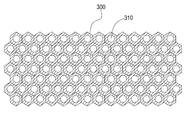
도 1은 본 발명의 일 실시예에 따른 EUV 리소그래피용 펠리클의 일 평면도이다.1 is a plan view of a pellicle for EUV lithography according to an embodiment of the invention.
도 1을 참조하면, 본 발명의 일 실시예에 따른 EUV 리소그래피용 펠리클은 복수개의 홀(310)을 포함하고, 소광계수가 0.02 이하인 물질로 구성된 다공성 펠리클 박막(300)이다.Referring to FIG. 1, a pellicle for EUV lithography according to an exemplary embodiment of the present invention is a porous
즉, EUV 리소그래피용 다공성 펠리클 박막(300)은 EUV 투과율이 높은 물질인 소광계수가 0 초과 및 0.02 이하인 물질을 포함하는 것이 바람직하다.That is, the
예컨대, EUV 리소그라피 마스크용 펠리클은 기본적으로 마스크의 오염물 유입을 방지하는 마스크 보호막이다. 나아가, EUV 리소그라피 마스크용 보호막으로 사용하기 위하여는 EUV 투과율이 높은 물질을 선택하는 것이 바람직하다.For example, a pellicle for an EUV lithography mask is basically a mask protecting film for preventing contamination of the mask. Furthermore, for use as a protective film for an EUV lithography mask, it is preferable to select a substance having a high EUV transmittance.
이러한 EUV 투과율은 물질의 광학상수 중 소광계수(extinction coefficient)와 관련이 있다.This EUV transmissivity is related to the extinction coefficient of the optical constants of the material.
<식 1><Formula 1>
n=1-δ+iβn = 1 -? + i?
상기 식 1과 같이 표현되는 EUV / soft x-ray 영역에서의 광학상수 복소 굴절률 방정식에서, 굴절률(n)의 실수부인 δ를 굴절계수 또는 굴절지수라 하고, 허수부 β를 소광계수라 한다.In the optical constant complex refractive index equation in the EUV / soft x-ray region expressed by Equation (1), a real number δ of the refractive index (n) is referred to as refraction index or refractive index, and the imaginary portion?
따라서, EUV 리소그래피용 펠리클 후보로 우선시되는 물질은 소광계수가 낮아 EUV 의 흡수가 적은 물질이 바람직하다.Therefore, a substance preferentially selected as a candidate for a pellicle for EUV lithography is preferably a substance having a low extinction coefficient and a low absorption of EUV.
예를 들어, 소광계수가 0.02 이하인 물질은 Zr, Mo, Y, Si, Rb, Sr, Nb 또는 Ru를 포함할 수 있다. 예를 들어, 실리콘(Si)은 소광계수가 0.001826으로서, 소광계수가 낮아 EUV의 흡수가 적은 물질로서, EUV 리소그래피용 펠리클 물질로 적합하다.For example, a material having an extinction coefficient of 0.02 or less may include Zr, Mo, Y, Si, Rb, Sr, Nb, or Ru. For example, silicon (Si) has an extinction coefficient of 0.001826, a low extinction coefficient and a low absorption of EUV, and is suitable as a pellicle material for EUV lithography.
한편, 이러한 펠리클 물질의 소광계수가 낮더라도, 펠리클의 두께가 증가할수록 EUV 투과율은 낮아지기 때문에, 두께를 증가시켜 강도를 향상시키기에는 일정한 한계가 있다.On the other hand, even if the extinction coefficient of such a pellicle material is low, since the EUV transmittance is lowered as the thickness of the pellicle increases, there is a certain limit to increase the thickness and improve the strength.
따라서, 본 발명은 복수개의 홀(310)을 포함하는 다공성 박막 자체를 펠리클로 사용하였다. 즉, 이러한 다공성 펠리클 박막(300)의 홀(310)을 통해 EUV 광이 직접 통과할 수 있기 때문에 다공성 박막으로 흡수되는 양을 줄일 수 있어 두께를 좀 더 증가시켜도 원하는 EUV 투과율을 만족시킬 수 있게 된다.Accordingly, the porous thin film including a plurality of
따라서, 복수개의 홀(310)을 포함하는 다공성 펠리클 박막(300)은 홀이 없는 단일 박막 형태의 펠리클보다 높은 EUV 투과율을 가지면서도 두께를 두껍게 제작할 수 있으므로 향상된 강도를 확보할 수 있다.Accordingly, the
이때의 홀(310)의 직경은 1 ㎛ 이하인 것을 특징으로 한다. 만일 홀(310)의 직경이 1 ㎛를 초과하는 경우, 펠리클 투과 이후의 EUV 광의 세기 분포의 불균일 문제가 발생할 수 있다.At this time, the diameter of the
따라서 이러한 홀(310)의 직경을 1 ㎛ 이하의 나노 사이즈로 설정함으로써, 펠리클을 투과한 이후에도 EUV 광의 세기 분포의 불균일 문제를 방지할 수 있다.Therefore, by setting the diameter of the
또한, 이러한 홀(310)의 직경과 홀(310) 피치(pitch)의 비율은 5:10 내지 9:10 인 것이 바람직하다.The ratio of the diameter of the
홀(310)의 직경과 홀(310) 피치의 비율은 5:10보다 작은 경우, 즉, 홀(310)의 직경이 홀(310) 피치의 1/2 크기 미만인 경우, 다공성 펠리클 박막(300)의 전체 면적 중 홀들(310)의 면적 비율이 작기 때문에, 홀이 없는 단일박막 대비 다공성 펠리클 박막(300)의 EUV 투과율의 상승폭이 높지 않다. 따라서, 다공성 두께를 두껍게 하여 강도를 향상시키기에는 한계가 있다.If the ratio of the diameter of the
한편, 이러한 다공성 펠리클 박막(300) 상에 위치하고, 소광계수가 0 초과 및 0.02 이하인 물질로 구성된 캡층(미도시)을 더 포함할 수 있다.On the other hand, it may further include a cap layer (not shown) formed on the
예를 들어, 이러한 캡층(미도시)은 Zr, Mo, Y, Si, Rb, Sr, Nb 또는 Ru를 포함할 수 있다.
For example, such a cap layer (not shown) may include Zr, Mo, Y, Si, Rb, Sr, Nb or Ru.
도 2는 본 발명의 일 실시예에 따른 EUV 리소그래피용 펠리클의 사용예를 나타낸 도면이다.2 is a view showing an example of using a pellicle for EUV lithography according to an embodiment of the present invention.
도 2를 참조하면, 본 발명의 일 실시예에 따른 다공성 펠리클 박막을 EUV 마스크의 보호막으로 사용한 개념도이다. 이 경우, 펠리클 장착용 프레임을 통하여 다공성 펠리클 박막을 EUV 마스크 상에 위치시킨다.Referring to FIG. 2, a porous pellicle thin film according to an embodiment of the present invention is used as a protective film of an EUV mask. In this case, the porous pellicle thin film is placed on the EUV mask through the pellicle mounting frame.
따라서, EUV 광이 다공성 펠리클 박막을 지나 EUV 마스크에서 반사되어 다시 다공성 펠리클 박막을 지나가게 되는데, 이러한 다공성 펠리클 박막의 높은 투과율에 의하여 광원의 손실을 최소화 할 수 있다.Therefore, the EUV light is reflected by the EUV mask through the porous pellicle thin film, and then passes through the porous pellicle thin film. The loss of the light source can be minimized by the high transmittance of the porous pellicle thin film.
또한, 다공성 펠리클 박막의 두께를 증가시켜 향상된 강도를 갖기 때문에 강도를 보강하기 위한 별도의 지지구조체가 필요하지 않으므로, 종래의 지지구조체의 추가에 따른 펠리클 투과 후 EUV 광의 세기가 불균일해지는 단점이 없다.
In addition, since the thickness of the porous pellicle film is increased to have an improved strength, there is no disadvantage that the strength of the EUV light after the penetration of the pellicle becomes uneven due to the addition of the conventional support structure, since a separate support structure for reinforcing the strength is not needed.
도 3 내지 도 7은 본 발명의 일 실시예에 따른 EUV 리소그래피용 펠리클 제조방법을 공정단계에 따라 나타낸 사시도들이다.FIGS. 3 to 7 are perspective views illustrating a method of manufacturing a pellicle for EUV lithography according to an embodiment of the present invention, according to a process step. FIG.
도 3을 참조하면, 나노 크기의 홀(110)이 형성된 다공성 구조체(100)를 준비한다.Referring to FIG. 3, a
예를 들어, 이러한 다공성 구조체(100)는 양극 산화 알루미늄(Anodic Aluminum Oxide, AAO)을 포함할 수 있다.For example, such a
도 4를 참조하면, 상기 다공성 구조체(100)의 홀(110)에 템플릿 물질을 주입한다. 따라서, 이렇게 주입된 템플릿 물질은 경화되어 다공성 구조체(110)의 반대 형태를 포함하는 템플릿(200)을 형성할 수 있다. 즉, 복수개의 돌기(도 5의 210)를 포함하는 템플릿(200)을 형성할 수 있다.Referring to FIG. 4, a template material is injected into the
이때의 템플릿 물질은 PDMS 또는 PMMA일 수 있다.The template material may be PDMS or PMMA.
또한, 이러한 템플릿 물질의 주입방법으로 용액 주입법 등 다양한 주입법을 이용할 수 있다. 예를 들어, AAO 다공성 구조체(100)에 PMMA 용액을 주입하여 흡착시킨 뒤 경화시켜 PMMA 템플릿(200)을 형성할 수 있다.In addition, various injection methods such as a solution injection method can be used as a method of injecting the template material. For example, the
한편, 이러한 템플릿 물질은 다공성 구조체(100)의 홀(110) 뿐 만 아니라 다공성 구조체(100)의 상부를 덮는 형태로 흡착시킨 뒤 경화시킬 수 있다.The template material may be adsorbed to the
한편, 상기 다공성 구조체(100)의 홀(110)에 템플릿 물질을 주입하는 단계는, 상기 템플릿 물질을 주입한 후, 일정 시간 진공 상태를 유지하는 단계를 더 포함할 수 있다.The step of injecting the template material into the
따라서, 템플릿 물질을 주입한 후에 일정 시간 진공 상태를 유지함으로써, 모세관 현상에 의해 템플릿 물질이 다공성 구조체의 홀을 보다 잘 채울 수 있다. 즉, 진공 상태 유지 단계를 통하여 템플릿 물질로 상기 다공성 구조체의 홀을 메우는 충진률을 증가시킬 수 있다.Therefore, by maintaining the vacuum state for a certain period of time after the injection of the template material, the template material can fill the hole of the porous structure better by the capillary phenomenon. That is, the filling rate for filling the holes of the porous structure with the template material can be increased through the vacuum state holding step.
따라서, 이와 같이 충진률을 증가시킴으로써, 보다 정교하게 다공성 구조체를 만들 수 있는 장점이 있다.Therefore, by increasing the filling rate in this manner, there is an advantage that a porous structure can be more precisely formed.
도 5를 참조하면, 상기 다공성 구조체(100)를 제거한다.Referring to FIG. 5, the
따라서, 이러한 다공성 구조체(100)는 복수개의 홀(110)을 포함하는 구조인 바, 이러한 다공성 구조체(100)를 제거할 경우, 이러한 다공성 구조체(100)의 반대 형태인 복수개의 돌기(210)를 포함하는 템플릿(200)만 남게 된다.Therefore, when the
이때의 다공성 구조체(100)는 습식식각공정, 적용몰드에 이형제를 사용하는 방법 또는 테프론코팅을 이용한 분리법 등 다공성 구조체(100)만 선택적으로 제거할 수 있는 다양한 방법을 이용하여 제거할 수 있다. 예를 들어, AAO 다공성 구조체는 습식식각공정을 통해 제거할 수 있다.At this time, the
도 6을 참조하면, 상기 템플릿(200) 상에 펠리클용 물질을 코팅하여 상기 다공성 구조체(100)의 형태를 포함하는 다공성 펠리클 막 구조물(300)을 형성한다.Referring to FIG. 6, a pellicle material is coated on the
예컨대, 상부에 복수개의 돌기(210)가 위치하는 템플릿(200) 상에 펠리클용 물질을 코팅하여 복수개의 홀(도 7의 310)이 채워진 다공성 펠리클 막 구조물(300)을 형성할 수 있다.For example, a porous
이때의 펠리클용 물질은 Zr, Mo, Y, Si, Rb, Sr, Nb 또는 Ru를 포함할 수 있다.The material for the pellicle may include Zr, Mo, Y, Si, Rb, Sr, Nb or Ru.
이러한 펠리클용 물질은 원자층증착법(ALD), 스퍼터링법(Sputter), 화학기상증착법(CVD), 이온빔 증착법(IBD) 또는 전기도금법(Electro plating) 등 다양한 박막증착법을 사용하여 템플릿(200) 상에 코팅할 수 있다.The pellicle material may be deposited on the
예를 들어, 복수개의 홀을 포함하는 AAO 다공성 구조체를 2회의 복제법을 이용함으로써, AAO 구조체의 형태와 동일한 복수개의 홀(310)을 포함하는 다공성 펠리클 박막(300)을 형성할 수 있다.For example, the
한편, 이러한 다공성 구조체(100)의 홀(110)의 직경이나 박막의 두께를 미리 조절하여 최종 형성되는 다공성 펠리클 박막(도 7의 300)의 형태를 조절할 수 있다. 예컨대, AAO 다공성 구조체는 AAO 성장법을 통해 홀의 직경이나 박막 두께의 조절이 가능하다.Meanwhile, the shape of the finally formed porous pellicle thin film (300 in FIG. 7) can be adjusted by adjusting the diameter of the
도 7을 참조하면, 상기 템플릿(200)을 제거한다.Referring to FIG. 7, the
이러한 템플릿만 선택적으로 제거할 수 있는 습식식각법 등 다양한 제거방법을 이용할 수 있다. 예를 들어, PMMA 템플릿을 습식식각법을 이용하여 제거할 수 있다.A variety of removal methods such as a wet etching method capable of selectively removing only these templates can be used. For example, the PMMA template can be removed by wet etching.
따라서, 최종적으로 복수개의 홀(310)을 포함하는 다공성 펠리클 박막(300)만 남게 된다.
Therefore, only the
단일 박막 및 다공성 박막의 투과율 측정Measurement of transmittance of single thin film and porous thin film
도 8은 본 발명의 일 실시예에 따른 EUV 리소그래피용 펠리클의 홀의 직경 및 홀 피치 비율에 따른 모식도들이다.Figure 8 is a schematic diagram according to the diameter and hole pitch ratio of a hole of a pellicle for EUV lithography according to an embodiment of the present invention.
도 8(a)는 펠리클의 홀의 직경 및 홀 피치 비율이 5:10인 경우이고, 도 8(b)는 펠리클의 홀의 직경 및 홀 피치 비율이 8:10인 경우이고, 도 8(c)는 펠리클의 홀의 직경 및 홀 피치 비율이 9:10인 경우이다.8 (a) shows a case where the hole diameter and the hole pitch ratio of the pellicle are 5:10, FIG. 8 (b) shows the case where the hole diameter and the hole pitch ratio of the pellicle are 8:10, And the hole diameter and hole pitch ratio of the pellicle are 9:10.
홀이 없는 Si 단일박막과 도 8과 같은 펠리클의 홀의 직경 및 홀 피치 비율을 갖는 Si 다공성 박막들의 두께에 따른 투과율을 측정하였다.The transmittance of Si single thin film without holes and the thickness of Si porous thin films having hole diameter and hole pitch ratio of pellicle holes as shown in Fig. 8 were measured.
도 9는 Si 단일박막과 Si 다공성박막의 두께에 따른 투과율을 측정한 그래프이다.9 is a graph showing the transmittance according to the thickness of the Si single thin film and the Si porous thin film.
또한, 홀이 없는 Zr 단일박막과 도 8과 같은 펠리클의 홀의 직경 및 홀 피치 비율을 갖는 Zr 다공성 박막들의 두께에 따른 투과율을 측정하였다.In addition, the transmittance according to the thickness of the Zr porous thin film having the hole diameter and hole pitch ratio of the hole of the pellicle as shown in Fig. 8 and the Zr single thin film without holes was measured.
도 10은 Zr 단일박막과 Zr 다공성박막의 두께에 따른 투과율을 측정한 그래프이다.10 is a graph showing the transmittance according to the thickness of the Zr single thin film and the Zr porous thin film.
도 9 및 도 10에 의한 EUV 투과율 결과를 하기 표 1 내지 표 4로 나타내었다.The EUV transmittance results according to Figs. 9 and 10 are shown in the following Tables 1 to 4.
하기 표 1은 홀이 없는 단일박막의 두께에 따른 EUV 투과율을 나타낸 표이다.Table 1 below shows the EUV transmissivity according to the thickness of a single thin film without holes.
하기 표 2는 홀의 직경 및 홀 피치 비율이 5:10인 경우로서 박막의 두께에 따른 EUV 투과율을 나타낸 표이다.Table 2 below shows the EUV transmissivity according to the thickness of the thin film when the hole diameter and the hole pitch ratio are 5:10.
하기 표 3은 홀의 직경 및 홀 피치 비율이 8:10인 경우로서 박막의 두께에 따른 EUV 투과율을 나타낸 표이다.Table 3 below is a table showing the EUV transmissivity according to the thickness of the thin film when the hole diameter and the hole pitch ratio are 8:10.
하기 표 4는 홀의 직경 및 홀 피치 비율이 9:10인 경우로서 박막의 두께에 따른 EUV 투과율을 나타낸 표이다.Table 4 below shows the EUV transmissivity according to the thickness of the thin film when the hole diameter and the hole pitch ratio are 9:10.
도 9, 도 10 및 표 1 내지 표 4를 참조하면, 홀의 직경 및 홀 피치 비율이 9:10 다공성 박막의 경우 200 nm 두께에서 단일박막 50 nm 두께의 투과율과 비슷한 수치를 나타냄을 알 수 있다.Referring to FIGS. 9, 10 and Tables 1 to 4, it can be seen that the hole diameter and the hole pitch ratio are similar to the transmittance of a single thin film of 50 nm thickness at a thickness of 200 nm for a 9:10 porous thin film.
따라서, 다공성 박막으로 펠리클을 제작할 경우 같은 투과율을 단일 박막보다 더 두껍게 만들 수 있어서 강도를 높일 수 있다는 장점이 있다.
Therefore, when the pellicle is made into a porous thin film, the same transmittance can be made thicker than a single thin film, thereby increasing the strength of the pellicle.
한편, 본 명세서와 도면에 개시된 본 발명의 실시 예들은 이해를 돕기 위해 특정 예를 제시한 것에 지나지 않으며, 본 발명의 범위를 한정하고자 하는 것은 아니다. 여기에 개시된 실시 예들 이외에도 본 발명의 기술적 사상에 바탕을 둔 다른 변형 예들이 실시 가능하다는 것은, 본 발명이 속하는 기술 분야에서 통상의 지식을 가진 자에게 자명한 것이다.It should be noted that the embodiments of the present invention disclosed in the present specification and drawings are only illustrative of specific examples for the purpose of understanding and are not intended to limit the scope of the present invention. It will be apparent to those skilled in the art that other modifications based on the technical idea of the present invention are possible in addition to the embodiments disclosed herein.
100: 다공성 구조체 110: 홀
200: 템플릿 210: 돌기
300: 다공성 펠리클 박막 310: 홀100: Porous structure 110: Hole
200: template 210: projection
300: porous pellicle thin film 310: hole
Claims (8)
상기 다공성 구조체의 홀에 템플릿 물질을 주입하여 상기 다공성 구조체의 반대 형태를 포함하는 나노 크기의 직경 및 피치를 갖는 복수개의 돌기를 포함하는 템플릿을 형성하는 단계;
상기 다공성 구조체를 제거하는 단계;
상기 템플릿 상에 펠리클용 물질을 코팅하여 상기 다공성 구조체의 형태를 포함하는 다공성 펠리클 막 구조물을 형성하는 단계; 및
상기 다공성 펠리클 막 구조물로부터 상기 템플릿을 제거하여 다공성 펠리클 박막을 형성하는 단계를 포함하고,
상기 다공성 펠리클 박막은,
두께가 150 nm 내지 200 nm이고, 홀의 직경 대 피치의 비율이 8:10 내지 9:10 이며, EUV 투과율이 75% 이상 및 100% 이하인, EUV 리소그래피용 펠리클 제조방법.Preparing a porous structure having a nano-sized hole formed therein;
Forming a template including a plurality of protrusions having a nano-sized diameter and pitch including an opposite shape of the porous structure by injecting a template material into holes of the porous structure;
Removing the porous structure;
Coating a material for pellicle on the template to form a porous pellicle membrane structure including the shape of the porous structure; And
Removing the template from the porous pellicle membrane structure to form a porous pellicle membrane,
The porous pellicle thin film may be formed,
Wherein the thickness is from 150 nm to 200 nm, the ratio of the diameter of the holes to the pitch is from 8:10 to 9:10, and the EUV transmittance is not less than 75% and not more than 100%.
상기 다공성 구조체는 양극 산화 알루미늄을 포함하는 것을 특징으로 하는 EUV 리소그래피용 펠리클 제조방법.5. The method of claim 4,
Wherein the porous structure comprises anodized aluminum. ≪ RTI ID = 0.0 > 11. < / RTI >
상기 템플릿 물질은 PDMS 또는 PMMA인 것을 특징으로 하는 EUV 리소그래피용 펠리클 제조방법.5. The method of claim 4,
Wherein the template material is PDMS or PMMA. ≪ RTI ID = 0.0 > 11. < / RTI >
상기 다공성 구조체의 홀에 템플릿 물질을 주입하는 단계는,
상기 템플릿 물질을 주입한 후, 일정 시간 진공 상태를 유지하여 상기 템플릿 물질로 상기 다공성 구조체의 홀을 메우는 충진률을 증가시키는 것을 특징으로 하는 EUV 리소그래피용 펠리클 제조방법.5. The method of claim 4,
Wherein the step of injecting the template material into the hole of the porous structure comprises:
Wherein the template material is injected and maintained in a vacuum state for a predetermined period of time to increase the filling rate of filling the holes of the porous structure with the template material.
상기 펠리클용 물질은 Zr, Mo, Y, Si, Rb, Sr, Nb 또는 Ru를 포함하는 EUV 리소그래피용 펠리클 제조방법.5. The method of claim 4,
Wherein the material for pellicle comprises Zr, Mo, Y, Si, Rb, Sr, Nb or Ru.
Priority Applications (4)
| Application Number | Priority Date | Filing Date | Title |
|---|---|---|---|
| KR1020140046218A KR101680937B1 (en) | 2014-04-17 | 2014-04-17 | Pellicle for EUV Lithography and method of fabricating the same |
| PCT/KR2015/003783 WO2015160185A1 (en) | 2014-04-17 | 2015-04-15 | Pellicle for euv lithography |
| CN201580020112.6A CN106233202B (en) | 2014-04-17 | 2015-04-15 | Pellicle for EUV lithography |
| US15/304,275 US9958770B2 (en) | 2014-04-17 | 2015-04-15 | Pellicle for EUV lithography |
Applications Claiming Priority (1)
| Application Number | Priority Date | Filing Date | Title |
|---|---|---|---|
| KR1020140046218A KR101680937B1 (en) | 2014-04-17 | 2014-04-17 | Pellicle for EUV Lithography and method of fabricating the same |
Publications (2)
| Publication Number | Publication Date |
|---|---|
| KR20150121293A KR20150121293A (en) | 2015-10-29 |
| KR101680937B1 true KR101680937B1 (en) | 2016-11-30 |
Family
ID=54430304
Family Applications (1)
| Application Number | Title | Priority Date | Filing Date |
|---|---|---|---|
| KR1020140046218A Active KR101680937B1 (en) | 2014-04-17 | 2014-04-17 | Pellicle for EUV Lithography and method of fabricating the same |
Country Status (1)
| Country | Link |
|---|---|
| KR (1) | KR101680937B1 (en) |
Families Citing this family (9)
| Publication number | Priority date | Publication date | Assignee | Title |
|---|---|---|---|---|
| NL2018691B1 (en) | 2016-04-25 | 2018-03-13 | Asml Netherlands Bv | A membrane for euv lithography |
| KR101900720B1 (en) | 2017-11-10 | 2018-09-20 | 주식회사 에스앤에스텍 | Pellicle for Extreme Ultraviolet(EUV) Lithography and Method for fabricating the same |
| KR101981950B1 (en) * | 2017-11-10 | 2019-05-24 | 주식회사 에스앤에스텍 | Pellicle for Extreme Ultraviolet Lithography |
| KR102782966B1 (en) * | 2019-10-22 | 2025-03-18 | 삼성전자주식회사 | pellicle for reflective mask |
| KR102691828B1 (en) * | 2021-07-27 | 2024-08-05 | (주)휴넷플러스 | Manufacturing method of pelicles with penetrating hole structure |
| KR102691826B1 (en) * | 2021-07-27 | 2024-08-05 | (주)휴넷플러스 | Manufacturing method of pelicle with concave-convex structure |
| KR102761774B1 (en) * | 2022-01-25 | 2025-02-05 | 한국과학기술원 | A method for manufacturing an euv pellicle based on a capping layer containing ruthenium structure and a multilayer membrane structure |
| KR20250050453A (en) | 2023-10-06 | 2025-04-15 | 한국과학기술원 | Pellicle for EUV lithography and method of manufacturing pellicle for EUV lithography |
| KR20250075926A (en) | 2023-11-22 | 2025-05-29 | 한국과학기술원 | Pellicle for EUV lithography and method of manufacturing pellicle for EUV lithography using stencil mask |
Citations (2)
| Publication number | Priority date | Publication date | Assignee | Title |
|---|---|---|---|---|
| JP2009282298A (en) | 2008-05-22 | 2009-12-03 | Shin-Etsu Chemical Co Ltd | Pellicle and method for manufacturing pellicle |
| JP2013165102A (en) | 2012-02-09 | 2013-08-22 | Shin Etsu Chem Co Ltd | Pellicle for euv |
-
2014
- 2014-04-17 KR KR1020140046218A patent/KR101680937B1/en active Active
Patent Citations (2)
| Publication number | Priority date | Publication date | Assignee | Title |
|---|---|---|---|---|
| JP2009282298A (en) | 2008-05-22 | 2009-12-03 | Shin-Etsu Chemical Co Ltd | Pellicle and method for manufacturing pellicle |
| JP2013165102A (en) | 2012-02-09 | 2013-08-22 | Shin Etsu Chem Co Ltd | Pellicle for euv |
Also Published As
| Publication number | Publication date |
|---|---|
| KR20150121293A (en) | 2015-10-29 |
Similar Documents
| Publication | Publication Date | Title |
|---|---|---|
| KR101680937B1 (en) | Pellicle for EUV Lithography and method of fabricating the same | |
| US9958770B2 (en) | Pellicle for EUV lithography | |
| KR101676095B1 (en) | Pellicle for EUV lithography | |
| KR101095681B1 (en) | Photomask for extreme ultraviolet lithography and its manufacturing method | |
| TWI430015B (en) | Imprinting method and patterning method | |
| JP6725097B2 (en) | Film mask, manufacturing method thereof, pattern forming method using the same, and pattern formed using the same | |
| CN113396468B (en) | Breathable cover sheet and method of using the same | |
| KR102273266B1 (en) | Manufacturing method for a Pellicle including integrated frame and membrane | |
| KR102089835B1 (en) | Film mask, preparing method thereof and pattern forming method using the same | |
| US20160054497A1 (en) | Inorganic polarizing plate and production method thereof | |
| JP5279862B2 (en) | Pellicle membrane, method for producing the same, and pellicle on which the membrane is stretched | |
| JP2008230232A (en) | MOLD, MOLD MANUFACTURING METHOD, IMPRINT DEVICE, IMPRINT METHOD, AND STRUCTURE MANUFACTURING METHOD USING IMPRINT METHOD | |
| US8308471B2 (en) | Mold, mold production process, processing apparatus, and processing method | |
| JP2011505270A (en) | Porous templates and imprint stacks for nanoimprint lithography | |
| JP2010258326A (en) | Nanoimprint mold and manufacturing method thereof | |
| TWI437360B (en) | EUV micro-shadow with a reflective mask base, and EUV micro-shadow with a reflective mask | |
| JP7060836B2 (en) | Imprint mold manufacturing method | |
| JP2011114046A (en) | Pattern forming method, pattern forming apparatus, nano-imprint mold, and method of manufacturing nano-imprint mold | |
| JP2014195088A (en) | Pattern forming apparatus by nano-imprint mold | |
| KR20180029384A (en) | Pellicle for an Extreme Ultraviolet(EUV) Lithography and method for fabricating the same | |
| JP7027823B2 (en) | Functional substrate and its manufacturing method, and imprint mold | |
| WO2020008978A1 (en) | Reinforced pellicle film and method for manufacturing same | |
| KR20130127287A (en) | Method for fabricating wire grid polarizer | |
| JP6972581B2 (en) | Imprint mold and imprint mold manufacturing method | |
| Nakagawa et al. | Selecting adhesive molecular layers with matched surface free energy and chemisorption for shape-fixed UV-cured thin films fabricated by laser-drilled screen printing and UV nanoimprinting |
Legal Events
| Date | Code | Title | Description |
|---|---|---|---|
| PA0109 | Patent application |
St.27 status event code: A-0-1-A10-A12-nap-PA0109 |
|
| R18-X000 | Changes to party contact information recorded |
St.27 status event code: A-3-3-R10-R18-oth-X000 |
|
| P11-X000 | Amendment of application requested |
St.27 status event code: A-2-2-P10-P11-nap-X000 |
|
| P13-X000 | Application amended |
St.27 status event code: A-2-2-P10-P13-nap-X000 |
|
| R18-X000 | Changes to party contact information recorded |
St.27 status event code: A-3-3-R10-R18-oth-X000 |
|
| PG1501 | Laying open of application |
St.27 status event code: A-1-1-Q10-Q12-nap-PG1501 |
|
| A201 | Request for examination | ||
| A302 | Request for accelerated examination | ||
| PA0201 | Request for examination |
St.27 status event code: A-1-2-D10-D11-exm-PA0201 |
|
| PA0302 | Request for accelerated examination |
St.27 status event code: A-1-2-D10-D17-exm-PA0302 St.27 status event code: A-1-2-D10-D16-exm-PA0302 |
|
| E902 | Notification of reason for refusal | ||
| PE0902 | Notice of grounds for rejection |
St.27 status event code: A-1-2-D10-D21-exm-PE0902 |
|
| AMND | Amendment | ||
| P11-X000 | Amendment of application requested |
St.27 status event code: A-2-2-P10-P11-nap-X000 |
|
| P13-X000 | Application amended |
St.27 status event code: A-2-2-P10-P13-nap-X000 |
|
| E601 | Decision to refuse application | ||
| PE0601 | Decision on rejection of patent |
St.27 status event code: N-2-6-B10-B15-exm-PE0601 |
|
| AMND | Amendment | ||
| E13-X000 | Pre-grant limitation requested |
St.27 status event code: A-2-3-E10-E13-lim-X000 |
|
| P11-X000 | Amendment of application requested |
St.27 status event code: A-2-2-P10-P11-nap-X000 |
|
| P13-X000 | Application amended |
St.27 status event code: A-2-2-P10-P13-nap-X000 |
|
| PX0901 | Re-examination |
St.27 status event code: A-2-3-E10-E12-rex-PX0901 |
|
| PX0701 | Decision of registration after re-examination |
St.27 status event code: A-3-4-F10-F13-rex-PX0701 |
|
| X701 | Decision to grant (after re-examination) | ||
| GRNT | Written decision to grant | ||
| PR0701 | Registration of establishment |
St.27 status event code: A-2-4-F10-F11-exm-PR0701 |
|
| PR1002 | Payment of registration fee |
St.27 status event code: A-2-2-U10-U11-oth-PR1002 Fee payment year number: 1 |
|
| PG1601 | Publication of registration |
St.27 status event code: A-4-4-Q10-Q13-nap-PG1601 |
|
| R18-X000 | Changes to party contact information recorded |
St.27 status event code: A-5-5-R10-R18-oth-X000 |
|
| R18-X000 | Changes to party contact information recorded |
St.27 status event code: A-5-5-R10-R18-oth-X000 |
|
| FPAY | Annual fee payment |
Payment date: 20190905 Year of fee payment: 4 |
|
| PR1001 | Payment of annual fee |
St.27 status event code: A-4-4-U10-U11-oth-PR1001 Fee payment year number: 4 |
|
| S14-X000 | Exclusive voluntary license recorded |
St.27 status event code: A-4-4-S10-S14-lic-X000 |
|
| PR1001 | Payment of annual fee |
St.27 status event code: A-4-4-U10-U11-oth-PR1001 Fee payment year number: 5 |
|
| PR1001 | Payment of annual fee |
St.27 status event code: A-4-4-U10-U11-oth-PR1001 Fee payment year number: 6 |
|
| PR1001 | Payment of annual fee |
St.27 status event code: A-4-4-U10-U11-oth-PR1001 Fee payment year number: 7 |
|
| PR1001 | Payment of annual fee |
St.27 status event code: A-4-4-U10-U11-oth-PR1001 Fee payment year number: 8 |
|
| S16-X000 | Recordation of exclusive voluntary license cancelled |
St.27 status event code: A-4-4-S10-S16-lic-X000 |
|
| PR1001 | Payment of annual fee |
St.27 status event code: A-4-4-U10-U11-oth-PR1001 Fee payment year number: 9 |
|
| PR1001 | Payment of annual fee |
St.27 status event code: A-4-4-U10-U11-oth-PR1001 Fee payment year number: 10 |
|
| U11 | Full renewal or maintenance fee paid |
Free format text: ST27 STATUS EVENT CODE: A-4-4-U10-U11-OTH-PR1001 (AS PROVIDED BY THE NATIONAL OFFICE) Year of fee payment: 10 |
|
| P22-X000 | Classification modified |
St.27 status event code: A-4-4-P10-P22-nap-X000 |