KR101678446B1 - Portable Chair - Google Patents
Portable Chair Download PDFInfo
- Publication number
- KR101678446B1 KR101678446B1 KR1020150048464A KR20150048464A KR101678446B1 KR 101678446 B1 KR101678446 B1 KR 101678446B1 KR 1020150048464 A KR1020150048464 A KR 1020150048464A KR 20150048464 A KR20150048464 A KR 20150048464A KR 101678446 B1 KR101678446 B1 KR 101678446B1
- Authority
- KR
- South Korea
- Prior art keywords
- frames
- support
- support member
- pole
- frame
- Prior art date
- Legal status (The legal status is an assumption and is not a legal conclusion. Google has not performed a legal analysis and makes no representation as to the accuracy of the status listed.)
- Active
Links
Images


Classifications
-
- A—HUMAN NECESSITIES
- A47—FURNITURE; DOMESTIC ARTICLES OR APPLIANCES; COFFEE MILLS; SPICE MILLS; SUCTION CLEANERS IN GENERAL
- A47C—CHAIRS; SOFAS; BEDS
- A47C9/00—Stools for specified purposes
- A47C9/10—Camp, travelling, or sports stools
-
- A—HUMAN NECESSITIES
- A47—FURNITURE; DOMESTIC ARTICLES OR APPLIANCES; COFFEE MILLS; SPICE MILLS; SUCTION CLEANERS IN GENERAL
- A47C—CHAIRS; SOFAS; BEDS
- A47C4/00—Foldable, collapsible or dismountable chairs
- A47C4/02—Dismountable chairs
- A47C4/022—Dismountable chairs connected by bars or wires
-
- A—HUMAN NECESSITIES
- A47—FURNITURE; DOMESTIC ARTICLES OR APPLIANCES; COFFEE MILLS; SPICE MILLS; SUCTION CLEANERS IN GENERAL
- A47C—CHAIRS; SOFAS; BEDS
- A47C4/00—Foldable, collapsible or dismountable chairs
- A47C4/02—Dismountable chairs
- A47C4/028—Upholstered chairs, e.g. metal, plastic or wooden chairs
Landscapes
- Life Sciences & Earth Sciences (AREA)
- Engineering & Computer Science (AREA)
- Wood Science & Technology (AREA)
- Special Chairs (AREA)
Abstract
본 발명은 휴대용 의자에 관한 것으로서, 본 발명의 일 실시예에 따른 휴대용 의자는, 지면 상에 서로 소정의 간격을 두고 배치되는 제1 지지 부재 및 제2 지지 부재, 각각의 일단은 상기 제1 및 제2 지지 부재에 분리 가능하게 결합되며, 각각의 타단은 지면과 소정 각도를 이루면서 전방을 향하여 연장되는 제1 및 제2 전방 폴 프레임, 각각의 일단은 상기 제1 및 제2 지지 부재에 분리 가능하게 결합되며, 각각의 타단은 지면과 소정 각도를 이루면서 후방을 향하여 연장되는 제1 및 제2 후방 폴 프레임 및 각각의 일단은 상기 제1 및 제2 후방 폴 프레임에 접촉하고, 각각의 타단은 지면에 접촉하여, 상기 제1 및 제2 후방 폴 프레임을 지지하는 제1 및 제2 지지 프레임을 포함한다. The present invention relates to a portable chair, and a portable chair according to an embodiment of the present invention includes a first support member and a second support member disposed on the ground at a predetermined interval from each other, First and second front pole frames detachably coupled to the second support member and each extending at a predetermined angle with respect to the ground and extending frontward, one end of each being detachably attachable to the first and second support members And the other end of each of the first and second rear pawl frames extends rearward at a predetermined angle with the ground and one end of each of the first and second rear pawl frames contacts the first and second rear pawl frames, And first and second support frames for supporting the first and second rear pole frames.
Description
본 발명은 휴대용 의자에 관한 것으로서, 보다 구체적으로 사용자가 용이하게 설치 및 조립할 수 있으며, 사용자가 휴식을 취하기 위해 등을 기대어도 안정적으로 사용자를 지지할 수 있는 휴대용 의자에 관한 것이다. BACKGROUND OF THE
최근 캠핑이나 낚시 등의 야외 활동의 증가로, 다양한 종류의 휴대용 의자가 제공되고 있다. Recently, as outdoor activities such as camping and fishing have increased, various kinds of portable chairs have been provided.
휴대용 의자는 휴대가 간편하고, 설치가 간단해야 한다. 야외의 경우 지면이 고르지 못한 경우가 많으므로, 고르지 못한 지면에 대해서도 용이하게 설치할 수 있어야 한다.Portable chairs should be easy to carry and simple to install. Since outdoor areas often have uneven surfaces, they should be easy to install even on uneven surfaces.
또한, 휴대용 의자는 사용시 사용자에게 안정감을 줄 수 있어야 한다. 사용자의 무게를 견고하게 지탱하여, 사용자에게 안정감을 줄 수 있어야 한다. 이러한 모든 조건을 충족시킬 수 있는 다양한 형태의 휴대용 의자를 제공하기 위한 다양한 시도가 이루어지고 있다. In addition, the portable chair should be able to provide a sense of stability to the user during use. The weight of the user should be firmly supported, and the user should be able to feel a sense of security. Various attempts have been made to provide various types of portable chairs capable of meeting all these conditions.
특허문헌 1에서는 사용시 여러 개의 일자형 다리들을 교차하여 고정 부재로 고정할 수 있는 의자를 개시하고 있다. 특허문헌 1의 경우 다리들을 한 점에 모아 고정시키는 구조로 되어있다. 이 경우, 다리들을 고른 지면에 설치하지 못하는 경우 의자의 좌우 및 전후 균형이 맞지 않아 사용자에게 불편함을 줄 수 있다. 뿐만 아니라, 의자의 등받이부를 포함하지 않으므로, 사용자가 앉는 자세 이외에 몸을 기대어 쉴 수 없어 사용에 있어 제약이 많았다.
본 발명은 상술한 문제점들을 해결하기 위한 것으로서, 본 발명은 사용자가 앉는 자세 이외에도 몸을 기대어 쉴 수 있는 휴대용 의자를 제공하기 위한 것이다.SUMMARY OF THE INVENTION The present invention has been made to solve the above-mentioned problems, and it is an object of the present invention to provide a portable chair which can rest on the body in addition to the user's sitting posture.
또한, 본 발명은 고르지 못한 지면에 대해서도 설치가 용이하며, 조립이 용이한 휴대용 의자를 제공하기 위한 것이다.The present invention also provides a portable chair that is easy to install even on uneven surfaces and is easy to assemble.
그리고 본 발명은 사용자를 지면에 대하여 안정적으로 지지하여 사용에 있어 안정감을 줄 수 있는 휴대용 의자를 제공하기 위한 것이다. The present invention is to provide a portable chair capable of stably supporting the user against the ground and providing a sense of stability in use.
또한, 본 발명은 팔걸이를 포함하는 휴대용 의자를 제공하기 위한 것이다. The present invention also provides a portable chair comprising an armrest.
본 발명의 일 실시예에 따른 휴대용 의자는, 지면 상에 서로 소정의 간격을 두고 배치되는 제1 지지 부재 및 제2 지지 부재, 각각의 일단은 상기 제1 및 제2 지지 부재에 분리 가능하게 결합되며, 각각의 타단은 지면과 소정 각도를 이루면서 전방을 향하여 연장되는 제1 및 제2 전방 폴 프레임, 각각의 일단은 상기 제1 및 제2 지지 부재에 분리 가능하게 결합되며, 각각의 타단은 지면과 소정 각도를 이루면서 후방을 향하여 연장되는 제1 및 제2 후방 폴 프레임, 및 각각의 일단은 상기 제1 및 제2 후방 폴 프레임에 접촉하고, 각각의 타단은 지면에 접촉하여, 상기 제1 및 제2 후방 폴 프레임을 지지하는 제1 및 제2 지지 프레임을 포함한다.A portable chair according to an embodiment of the present invention includes a first support member and a second support member disposed on the ground at a predetermined interval from each other and one end of each of the first and second support members is detachably coupled to the first and second support members And the other end of each of the first and second front pawl frames extends forward toward the front and forms a predetermined angle with the ground, one end of each of which is detachably coupled to the first and second support members, And one end of each of the first and second rear pawl frames is in contact with the first and second rear pawl frames and each of the other ends of the first and second rear pawl frames is in contact with the ground, And first and second support frames for supporting the second rear pole frame.
상기 제1 및 제2 지지 부재로부터 후방으로 이격되어 지면 상에 배치되는 하나 이상의 제3 지지 부재를 더 포함하며, 상기 제1 및 제2 지지 프레임들의 타단은 상기 제3 지지 부재에 분리 가능하게 결합될 수 있다. Further comprising at least one third support member spaced rearwardly from the first and second support members and disposed on the ground, wherein the other end of the first and second support frames is detachably coupled to the third support member .
상기 제3 지지 부재는, 2개의 상기 제3 지지 부재를 포함하며, 하나의 제3 지지 부재는 상기 제1 지지 부재의 후방에 위치하고, 다른 하나의 제3 지지 부재는 상기 제2 지지 부재의 후방에 위치하며, 상기 제1 지지 프레임의 타단은 그의 후방에 위치한 상기 제3 지지 부재에 분리 가능하게 결합되며, 상기 제2 지지 프레임의 타단은 그의 후방에 위치하는 상기 제3 지지 부재에 분리 가능하게 결합될 수 있다. Wherein the third support member includes two of the third support members, one third support member is located behind the first support member, and the other third support member is located behind the second support member Wherein the other end of the first support frame is detachably coupled to the third support member located at the rear of the first support frame and the other end of the second support frame is detachably attached to the third support member Can be combined.
상기 제1 및 제2 후방 폴 프레임에 각각 설치된 제1 및 제2 허브를 포함하며, 상기 제1 및 제2 지지 프레임들의 일단이 상기 제1 및 제2 허브에 각각 분리 가능하게 결합될 수 있다.And first and second hubs mounted on the first and second rear pole frames, respectively, and one end of the first and second support frames may be detachably coupled to the first and second hubs, respectively.
상기 제1 및 제2 전방 폴 프레임, 상기 제1 및 제2 후방 폴 프레임 및 상기 제1 및 제2 지지 프레임 중 하나 이상은 각각 제1 지지 부재, 제2 지지 부재, 제3 지지 부재, 제1 허브 또는 제2 허브에 탄성 줄로 연결될 수 있다.At least one of the first and second front pole frames, the first and second rear pole frames, and the first and second support frames, respectively, are a first support member, a second support member, a third support member, And may be connected to the hub or second hub by an elastic string.
상기 제1 및 제2 전방 폴 프레임, 상기 제1 및 제2 후방 폴 프레임 및 상기 제1 및 제2 지지 프레임 중 하나 이상은 하나 이상의 단위 프레임들이 탄성 줄에 의해 분리 가능하게 연결될 수 있다.At least one of the first and second front pole frames, the first and second rear pole frames, and the first and second support frames may be detachably connected to one or more unit frames by an elastic string.
상기 제1 및 제2 지지 부재를 연결하는 제1 중앙 지지 프레임을 더 포함할 수 있다.And a first center support frame connecting the first and second support members.
상기 2개의 제3 지지 부재를 연결하는 제2 중앙 지지 프레임을 더 포함할 수 있다.And a second center support frame connecting the two third support members.
상기 제1 및 제2 후방 폴 프레임은 상기 제1 및 제2 전방 폴 프레임보다 길이가 길 수 있다.The first and second rear pole frames may be longer than the first and second front pole frames.
상기 제1 및 제2 후방 폴 프레임은 지면에 대하여 60도 이하의 경사각을 갖도록 형성될 것이다.The first and second rear pole frames may be formed to have an inclination angle of 60 degrees or less with respect to the ground.
상기 제1 및 제2 전방 폴 프레임의 타단과 상기 제1 및 제2 후방 폴 프레임의 타단에 각각 분리 가능하게 연결되는 시트 천을 포함할 수 있다.And a sheet cloth detachably connected to the other ends of the first and second front pole frames and the other ends of the first and second rear pole frames, respectively.
상기 시트 천에는 상기 제1 및 제2 전방 폴 프레임의 타단과 상기 제1 및 제2 후방 폴 프레임의 타단이 각각 삽입되는 포켓을 포함할 수 있다.The seat cloth may include pockets into which the other ends of the first and second front pole frames and the other ends of the first and second rear pole frames are respectively inserted.
각각의 일단은 상기 제1 및 제2 허브에 결합되고, 타단은 상기 제1 및 제2 전방 폴 프레임의 타단에 결합되는 제1 및 제2 팔걸이용 프레임을 더 포함할 수 있다. And the first and second arm frames are coupled to the first and second hubs, respectively, and the other ends thereof are coupled to the other ends of the first and second front pole frames.
상기 제1 및 제2 팔걸이용 프레임은 상기 제1 및 제2 허브에 회전 가능하게 결합될 수 있다.The first and second armrest frames may be rotatably coupled to the first and second hubs.
상기 제1 및 제2 허브에는 각각 브라켓이 형성되고, 상기 제1 및 제2 팔걸이용 프레임의 일단에는 상기 각각의 브라켓에 회전 가능하게 결합되는 힌지 조인트가 형성될 수 있다.A bracket may be formed on each of the first and second hubs, and a hinge joint may be formed on one end of the first and second armrest frames to be rotatably coupled to the respective brackets.
각각의 상기 제1 및 제2 팔걸이용 프레임의 타단에는 각각 제1 및 제2 연결 부재가 결합되며, 상기 제1 및 제2 연결 부재는, 각각, 상기 제1 및 제2 팔걸이용 프레임이 삽입되는 삽입홀을 포함하는 제1 하우징, 상기 제1 및 제2 전방 폴 프레임이 관통하는 관통홀을 포함하는 제2 하우징을 포함할 수 있다. First and second connecting members are coupled to the other ends of the first and second armrest frames, respectively, and the first and second connecting members are respectively inserted into the first and second armrest frames A first housing including an insertion hole, and a second housing including a through hole through which the first and second front pole frames pass.
상기 제1 하우징은 상기 제1 및 제2 팔걸이용 프레임의 삽입 방향을 따라 연장된 슬롯을 포함하고, 상기 제1 및 제2 팔걸이용 프레임은 각각 상기 슬롯 내부에 배치되는 돌출부를 포함하여, 상기 슬롯을 따라 돌출부가 움직이도록 형성될 수 있다.Wherein the first housing includes a slot extending along an insertion direction of the first and second armrest frames, and the first and second armrest frames each include a protrusion disposed within the slot, As shown in FIG.
본 발명은 사용자가 앉는 자세 이외에도 몸을 기대어 쉴 수 있는 휴대용 의자를 제공할 수 있다.The present invention can provide a portable chair that can rest on the body in addition to the user's sitting posture.
또한, 본 발명은 고르지 못한 지면에 대해서도 설치가 용이하며, 조립이 용이한 휴대용 의자를 제공할 수 있다. Further, the present invention can provide a portable chair that is easy to install even on uneven surfaces and is easy to assemble.
그리고 본 발명은 사용자를 지면에 대하여 안정적으로 지지하여 사용에 있어 안정감을 줄 수 있는 휴대용 의자를 제공할 수 있다. In addition, the present invention can provide a portable chair that can stably support a user against the ground to provide a sense of stability in use.
또한, 본 발명은 팔걸이를 포함하는 휴대용 의자를 제공할 수 있다. In addition, the present invention can provide a portable chair including an armrest.
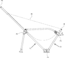
도 1은 본 발명의 제1 실시예에 따른 휴대용 의자 프레임의 측면 사시도이다.
도 2는 도 1의 휴대용 의자 프레임의 측면 분리 사시도이다.
도 3은 도 1의 휴대용 의자 프레임의 측면도이다.
도 4는 도 1의 휴대용 의자 프레임에 시트 천이 적용된 휴대용 의자를 나타내는 측면 사시도이다.
도 5는 본 발명의 제2 실시예에 따른 휴대용 의자 프레임의 측면 사시도이다.
도 6은 도 5의 휴대용 의자 프레임의 제1 허브를 확대하여 나타낸 부분 확대도이다.
도 7a 및 도 7b는 도 5의 휴대용 의자 프레임의 제1 연결 부재를 확대하여 나타낸 부분 확대도이다.
도 8은 도 5의 휴대용 의자 프레임에 시트 천이 적용된 휴대용 의자를 나타내는 측면도이다.
도 9는 도 5의 휴대용 의자 프레임의 측면 분리 사시도이다.1 is a side perspective view of a portable chair frame according to a first embodiment of the present invention.
Fig. 2 is a side view of the portable chair frame of Fig. 1. Fig.
3 is a side view of the portable chair frame of Fig.
4 is a side perspective view showing a portable chair to which a seat cloth is applied to the portable chair frame of FIG.
5 is a side perspective view of a portable chair frame according to a second embodiment of the present invention.
Fig. 6 is an enlarged partial enlarged view of the first hub of the portable chair frame of Fig. 5; Fig.
FIGS. 7A and 7B are enlarged partial enlarged views of the first connecting member of the portable chair frame of FIG. 5;
8 is a side view showing a portable chair to which a seat cloth is applied to the portable chair frame of Fig.
Fig. 9 is a side view perspective view of the portable chair frame of Fig. 5;
이하, 첨부된 도면들을 참조하여 본 발명의 일 실시예에 따른 휴대용 의자에 대하여 구체적으로 알아보자. Hereinafter, a portable chair according to an embodiment of the present invention will be described in detail with reference to the accompanying drawings.
도 1 내지 도 4는 본 발명의 제1 실시예에 따른 휴대용 의자에 관한 도면들이다. 1 to 4 are views of a portable chair according to a first embodiment of the present invention.
도 1에 도시된 바와 같이, 본 발명의 제1 실시예에 따른 휴대용 의자는, 제1 지지 부재(10), 제2 지지 부재(20), 제1 및 제2 전방 폴 프레임(110, 120), 제1 및 제2 후방 폴 프레임(130, 140) 및 제1 및 제2 지지 프레임(210, 220)을 포함한다.1, the portable chair according to the first embodiment of the present invention includes a
제1 및 제2 지지 부재(10, 20)는 지면 상에 소정의 간격을 두고 배치된다. 상기 제1 및 제2 전방 폴 프레임(110, 120)의 각각의 일단은 상기 제1 및 제2 지지 부재(10, 20)에 분리 가능하게 결합되며, 각각의 타단은 지면과 소정 각도를 이루면서 전방을 향해 연장된다. The first and
또한, 제1 및 제2 후방 폴 프레임(130, 140)의 각각의 일단도 상기 제1 및 제2 지지 부재(10, 20)에 분리 가능하게 결합되며, 각각의 타단은 지면과 소정 각도를 이루면서 후방을 향해 연장된다. One end of each of the first and second
본 명세서에서, "전방"은 휴대용 의자에서 사용자가 앉는 방향인 의자의 앞 부분을 향하는 방향을 의미하며, "후방"은 "전방"에 반대방향인 의자의 뒷부분을 향하는 방향을 의미한다. In the present specification, "forward" means a direction toward a front portion of a chair which is a direction in which a user sits in a portable chair, and "rear" means a direction toward a rear portion of a chair which is opposite to "forward ".
제1 지지 부재(10)를 중심으로 제1 전방 폴 프레임(110)과 제1 후방 폴 프레임(130)이 연결되어 사용자를 중심으로 의자의 좌측 프레임을 형성하고, 제2 지지 부재(20)를 중심으로 제2 전방 폴 프레임(120)과 제2 후방 폴 프레임(140)이 연결되어 사용자를 중심으로 의자의 우측 프레임을 형성한다. The first
제1 및 제2 전방 폴 프레임(110, 120)과 제1 및 제2 후방 폴 프레임(130, 140)에 시트 천(90)(도 4 참조)이 적용되어 의자를 형성하는 경우, 제1 및 제2 전방 폴 프레임(110, 120)은 사용자의 좌석부를 형성하며, 제1 및 제2 후방 폴 프레임(130, 140)은 사용자의 등받이부를 형성할 수 있다.When the seat cloth 90 (see FIG. 4) is applied to the first and second
제1 및 제2 후방 폴 프레임(130, 140)을 지지하기 위하여, 각각의 일단은 상기 제1 및 제2 후방 폴 프레임(130, 140)에 접촉하고, 각각의 타단은 지면에 접촉하여 제1 및 제2 후방 폴 프레임(130, 140)을 지지하는 제1 및 제2 지지 프레임(210, 220)이 형성된다.In order to support the first and second
상기 제1 및 제2 전방 폴 프레임(110, 120)으로 전달되는 사용자의 하중은 제1 및 제2 지지 부재(10, 20)를 통하여 지지되며, 제1 및 제2 후방 폴 프레임(130, 140)으로 전달되는 사용자의 하중은 제1 및 제2 지지 부재(10, 20) 및 제1 및 제2 지지 프레임(210, 220)을 통하여 지지되도록 형성된다. 사용자가 휴식을 위하여 의자에 앉는 경우, 사용자는 의자의 등받이에 기대게 되므로, 전방 폴 프레임들보다는 후방 폴 프레임들에 하중이 더 많이 전달된다. 본 발명의 경우 후방 폴 프레임들은 제1 및 제2 지지 부재와 제1 및 제2 지지 프레임들에 의하여 지지되기 때문에 후방 폴 프레임들을 안정적으로 지지할 수 있다. 그에 따라, 사용자가 휴식을 위하여 의자에 앉거나 기대는 경우에 안정적으로 사용자를 지지할 수 있는 휴대용 의자를 제공할 수 있다. The load of the user transmitted to the first and second
상기 제1 및 제2 지지 부재(10, 20)로부터 후방으로 이격되어 지면 상에 배치되는 하나 이상의 제3 지지 부재(30)를 더 포함할 수 있고, 상기 제1 및 제2 지지 프레임(210, 220)들의 타단은 상기 제3 지지 부재(30)에 분리 가능하게 결합될 수 있다. The first and
그에 따라, 제3 지지 부재(30)를 중심으로 제1 및 제2 지지 프레임(210, 220)들이 연결되어, 하중을 지면으로 전달할 수 있다. Accordingly, the first and second support frames 210 and 220 are connected to each other around the
제1, 제2 및 제3 지지 부재(10, 20, 30)의 경우 프레임들에 전달되는 하중을 지면으로 안정적으로 전달하며, 프레임들을 원하는 위치에 유지하게 할 수 있다. 그에 따라, 보다 안정적인 휴대용 의자를 제공할 수 있다. In the case of the first, second and
보다 구체적으로 제1, 제2 및 제3 지지 부재(10, 20, 30)들은 지면에 접촉하는 지지부와 폴 프레임 또는 지지 프레임이 삽입되는 2 이상의 삽입 홀들을 포함하도록 형성될 수 있다. 평면 형상의 지지부를 마련함으로써 지면에 대하여 안정적으로 고정할 수 있으며, 2 이상의 삽입 홀들을 포함함으로써 프레임들을 원하는 위치에 안정적으로 고정할 수 있다. More specifically, the first, second, and
본 실시예에서는, 제1, 제2 및 제3 지지 부재(10, 20, 30)가 형성된 것을 예시하고 있다. 그러나, 반드시 이에 제한되는 것은 아니며 제3 지지 부재(30)가 없이 제1 및 제2 지지 프레임(210, 220)들이 직접 지면으로 하중을 전달하게 형성될 수 있다. 이 경우, 제1 및 제2 지지 프레임(210, 220)들 각각의 지면에 대한 각도를 조절하여 배치할 수 있다.In this embodiment, the first, second, and
본 발명의 경우, 의자의 좌우 균형은 제1 및 제2 지지 부재(10, 20)로 유지될 수 있다. 그에 따라, 사용자는 제1 및 제2 지지 부재(10, 20)만을 수평하게 배치하면 의자의 좌우 균형을 맞출 수 있다. 제3 지지 부재(30)로는 의자의 등받이부의 기울기를 조절할 수 있다.In the case of the present invention, the left and right balances of the chair can be held by the first and
그에 따라, 제3 지지 부재(30)가 배치된 지면의 높이와 제1 및 제2 지지 부재(10, 20)가 배치된 지면의 높이가 다소 차이가 있더라도, 제1 및 제2 지지 부재(10, 20)가 배치된 지면의 높이만 동일하다면 좌우 균형을 맞춘 의자를 제공할 수 있다. 그에 따라, 의자가 설치되는 지면의 굴곡에 대한 영향력을 최소화하여, 지면에 대한 제약이 적고 설치가 용이한 휴대용 의자를 제공할 수 있다.Accordingly, even if the height of the ground on which the
한편, 상기 제1 및 제2 후방 폴 프레임(130, 140)에 제1 및 제2 허브(40, 50)가 각각 설치될 수 있다. 상기 제1 및 제2 허브(40, 50)에 상기 제1 및 제2 지지 프레임(210, 220)들의 일단이 각각 분리 가능하게 결합될 수 있다.Meanwhile, first and
도 1에서는, 제1 및 제2 허브(40, 50)가 제1 및 제2 후방 폴 프레임(130, 140) 상에 유지되도록, 후방 폴 프레임들을 관통하여 지나가도록 형성된 것을 도시하고 있다. 그러나, 반드시 이에 제한되는 것은 아니며, 제1 및 제2 후방 폴 프레임(130, 140)의 가운데 부분에 허브가 고정되게 하는 다양한 구조를 채택할 수도 있음은 물론이다. 1 illustrates that the first and
제1 및 제2 허브(40, 50)를 통하여 제1 및 제2 후방 폴 프레임(130, 140)과 제1 및 제2 지지 프레임(210, 220)을 안정적으로 고정할 수 있으며, 그에 따라 제1 및 제2 후방 폴 프레임(130, 140)을 지면에 대하여 안정적으로 지지하여 사용자에게 안정감을 줄 수 있는 의자를 제공할 수 있다.The first and second rear pole frames 130 and 140 and the first and second support frames 210 and 220 can be stably fixed through the first and
제1 및 제2 허브(40, 50)는 부채꼴 형상의 구조물로서, 지지 프레임이 삽입되는 제1 삽입홀과, 후방 폴 프레임이 삽입되는 제2 삽입홀을 포함하도록 형성될 수 있다. 제1 삽입홀과 제2 삽입홀 사이의 경사각을 조절함으로써, 후방 폴 프레임의 지면에 대한 경사각 또는 지지 프레임의 지면에 대한 경사각을 조절할 수 있다. 사용자에게 편안함을 줄 수 있는 경사각을 갖도록 조절할 수 있으며, 도 3에서 보다 구체적으로 설명하기로 한다. The first and
한편, 상기 제1 및 제2 지지 부재(10, 20)는 이를 연결하는 제1 중앙 지지 프레임(300)을 더 포함할 수 있다. 제1 중앙 지지 프레임(300)으로 제1 및 제2 지지 부재(10, 20)를 고정적으로 연결하기 때문에 사용자의 하중이 과도하게 부가되더라도 제1 및 제2 지지 부재(10, 20)의 간격이 벌어지거나, 위치가 틀어지는 것을 방지할 수 있다. 보다 큰 하중에도 견딜 수 있는 견고한 휴대용 의자를 제공할 수 있다. The first and
도 2에 도시된 바와 같이, 상기 제1 및 제2 전방 폴 프레임(110, 120), 상기 제1 및 제2 후방 폴 프레임(130, 140) 및 상기 제1 및 제2 지지 프레임(210, 220) 중 하나 이상은 각각 제1 지지 부재(10), 제2 지지 부재(20), 제3 지지 부재(30), 제1 허브(40) 또는 제2 허브(50)에 탄성 줄(S)로 연결될 수 있다. As shown in FIG. 2, the first and second front pole frames 110 and 120, the first and second rear pole frames 130 and 140, and the first and second support frames 210 and 220 May be connected to the
본 명세서에서, "분리 가능하게 결합"되어 있다는 것은 휴대시 프레임들을 분리하여 해체할 수 있으며, 사용시 프레임들을 결합하여 사용하도록 형성되었다는 것을 의미한다. 그에 따라, 폴 프레임, 지지 프레임들은 휴대와 사용을 위하여 접거나 결합하여 사용할 수 있음을 의미한다. As used herein, "detachably coupled" means that the portable frames can be separated and disassembled, and that they are configured for use in combination with the frames in use. Accordingly, the pole frame and the support frames can be folded or used for carrying and use.
사용자는 휴대시에는 제1 지지 부재(10), 제2 지지 부재(20) 및 제3 지지 부재(30)로부터 폴 프레임들을 분리하여 접을 수 있다. 뿐만 아니라, 지지 프레임도 제1 및 제2 허브(40, 50) 및 제3 지지 부재(30)로부터 분리하여 접을 수 있다. The user can separate and fold the pawl frames from the first supporting
더 나아가, 폴 프레임들 또는 지지 프레임들을 분리하더라도, 각각의 프레임들은 탄성 줄(S)을 통하여, 각각의 지지 부재 또는 허브에 연결되어 있으므로 사용자의 분실을 방지할 수 있다. Furthermore, even if the pawl frames or the support frames are separated, since each frame is connected to each support member or hub through the elastic string S, it is possible to prevent loss of the user.
따라서, 용이하게 접을 수 있고, 쉽게 조립할 수 있으며, 휴대가 간편한 휴대용 의자를 제공할 수 있다. Accordingly, it is possible to provide a portable chair which can be easily folded, assembled easily, and is portable.
또한, 상기 제1 및 제2 전방 폴 프레임(110, 120), 상기 제1 및 제2 후방 폴 프레임(130, 140) 및 상기 제1 및 제2 지지 프레임(210, 220) 중 하나 이상은 하나 이상의 폴 프레임들이 탄성 줄에 의해 분리 가능하게 연결될 수 있다.Also, at least one of the first and second front pole frames 110 and 120, the first and second rear pole frames 130 and 140, and the first and second support frames 210 and 220, The above-mentioned pawl frames can be releasably connected by an elastic string.
도 2에서는, 후술하는 바와 같이 상대적으로 다른 프레임들에 비하여 길이가 긴 제1 및 제2 후방 폴 프레임(130, 140)이 각각 3개의 단위 프레임들(131, 133, 135; 141, 143, 145)로 구성된 것을 도시하였다. 이 경우, 후방 폴 프레임들을 길게 형성하더라도 사용자가 용이하게 접어 휴대할 수 있는 휴대용 의자를 제공할 수 있다. 그러나 반드시 이에 제한되는 것은 아니며 다른 폴 프레임 또는 지지 프레임도 분리 가능하게 하나 이상의 프레임들로 구성될 수 있음은 물론이다. 2, the first and second rear pole frames 130 and 140, which are longer than the relatively different frames, are divided into three unit frames 131, 133, 135, 141, 143 and 145 ). In this case, it is possible to provide a portable chair that can be easily folded and carried by a user even if the rear pawl frames are elongated. However, it is needless to say that the present invention is not necessarily limited to this, and another pole frame or support frame may be detachably configured with one or more frames.
한편, 도 2에는, 제1 중앙 지지 프레임(300)은 제1 및 제2 지지 부재(10, 20)로부터 분리되지 않도록 도시되어 있다. 제1 중앙 지지 프레임(300)과 제1 및 제2 지지 부재(10, 20)의 조립체를 중심으로 다른 조립체들을 분리하여 접거나, 조립하게 하기 위함이다. 분리하여 접는 경우 부품들이 전부 분리되는 경우 부품들을 전부 분리해 놓으면 조립에 있어서 시간이 오래 걸리거나, 탄성 줄에 의해 부품들이 꼬이는 경우가 발생할 수 있다. 따라서, 제1 중앙 지지 프레임(300)과 제1 및 제2 지지 부재(10, 20)의 조립체를 유지하여, 즉, 휴대를 방해하지 않는 범위 내에서 일 부분은 조립된 상태로 유지하여 이 부분을 중심으로 분리 및 조립하도록 형성하여 휴대가 간편하면서도, 분리 및 조립이 편리한 휴대용 의자를 제공할 수 있다. On the other hand, in Fig. 2, the first
그러나 반드시 이에 제한되는 것은 아니며, 상기 제1 중앙 지지 프레임(300)도 또한 상기 제1 및 제2 지지 부재(10, 20)에 탄성 줄에 의해 분리 가능하게 결합될 수 있다. However, the present invention is not necessarily limited thereto, and the first
도 3에 도시된 바와 같이, 상기 제1 및 제2 후방 폴 프레임(130, 140)의 길이(L1)가 상기 제1 및 제2 전방 폴 프레임(110, 120)의 길이(L2)보다 길 수 있다. 상기 제1 및 제2 후방 폴 프레임(130, 140)의 길이(L1)를 상기 길이(L2)보다 길게 함으로써, 등받이부의 길이가 긴 의자를 제공할 수 있다. 등받이부의 길이가 길어짐으로써 사용자가 등 전체를 기댈 수 있는 의자를 제공할 수 있으며, 더 나아가 머리까지 기댈 수 있는 의자를 제공할 수 있다. 사용자에게 편안한 휴식을 제공할 수 있는 의자를 제공할 수 있다. The length L1 of the first and second rear pole frames 130 and 140 is longer than the length L2 of the first and second front pole frames 110 and 120 have. By making the length L1 of the first and second rear pawl frames 130 and 140 longer than the length L2, a chair having a long back can be provided. The length of the backrest is increased, so that the user can provide a chair that can lean the entire back, and furthermore, a chair that can lean against the head can be provided. It is possible to provide a chair capable of providing a comfortable rest to the user.
본 발명의 경우, 등받이부의 길이가 길어지더라도, 즉, 제1 및 제2 후방 폴 프레임(130, 140)의 길이가 길어지더라도, 제1 및 제2 후방 폴 프레임(130, 140)들은 제1 및 제2 지지 프레임(210, 220)으로 지지되도록 형성되기 때문에 사용자에게 안정감을 줄 수 있는 휴대용 휴식 의자를 제공할 수 있다.In the case of the present invention, even if the length of the backrest is long, that is, the length of the first and second rear pole frames 130 and 140 becomes long, the first and second rear pole frames 130 and 140 1 and the second support frames 210 and 220, it is possible to provide a portable rest chair capable of providing a user with a sense of stability.
또한, 상기 제1 및 제2 후방 폴 프레임(130, 140)은 지면에 대하여 60도 이하의 경사각(α) 갖도록 형성될 수 있다. 도 3의 실시예에서, 제1 및 제2 후방 폴 프레임(130, 140)은 지면에 대하여 대략 45도의 경사각(α)을 갖는다. 경사각이 낮아질수록 사용자 누워 쉬기 편해질 수 있으며, 사용자에게 편안함과 안락함을 줄 수 있는 휴대용 의자를 제공할 수 있다. In addition, the first and second rear pole frames 130 and 140 may be formed to have an inclination angle? Of 60 degrees or less with respect to the ground. In the embodiment of FIG. 3, the first and second rear pole frames 130, 140 have an inclination angle? Of approximately 45 degrees relative to the ground. The lower the inclination angle, the easier the user can lay down, and the portable chair can be provided to provide comfort and comfort to the user.
마찬가지로, 제1 및 제2 후방 폴 프레임(130, 140)들이 지면 쪽으로 기울어지더라도, 제1 및 제2 지지 프레임(210, 220)이 이를 지지하기 때문에, 사용자에게 안정감을 줄 수 있는 휴대용 의자를 제공할 수 있다. Similarly, even if the first and second rear pole frames 130 and 140 are inclined toward the ground, since the first and second support frames 210 and 220 support the portable chair, .
본 발명의 경우, 사용자가 등 전체와 머리 부분까지 기대어 쉴 수 있으며, 누운 자세로 쉴 수 있는 휴대용 휴식 의자를 제공할 수 있다. 앞서 설명한 바와 같이, 휴대가 간편하며, 사용자를 안정적으로 지지하여 사용자에게 안정감을 줄 수 있는 휴대용 휴식 의자를 제공할 수 있다. In the case of the present invention, a portable rest chair can be provided in which the user can rest up to the entire back and the head, and can rest in a lying position. As described above, it is possible to provide a portable rest chair which is easy to carry and which can support the user in a stable manner and give a sense of stability to the user.
도 4에 도시된 바와 같이, 상기 제1 및 제2 전방 폴 프레임(110, 120)의 타단과 상기 제1 및 제2 후방 폴 프레임(130, 140)의 타단에 각각 분리 가능하게 연결되는 시트 천(90)을 포함할 수 있다. 4, a sheet cloth (not shown) detachably connected to the other ends of the first and second front pole frames 110 and 120 and the other ends of the first and second rear pole frames 130 and 140, (90).
시트 천(90)이 각각의 폴 프레임에 분리 가능하게 조립되기 때문에, 휴대시 따로 분리하여 조립할 수 있는 휴대용 의자를 제공할 수 있다. 시트 천(90)이 분리 가능하기 때문에 야외 활동 후 분리하여 세탁이 가능하며, 동일한 의자 프레임에 대하여 다양한 디자인의 시트 천(90)을 바꾸어 사용할 수 있게 하여 사용자에게 심미감을 줄 수도 있다.Since the
또한, 상기 시트 천(90)에는 상기 제1 및 제2 전방 폴 프레임(110, 120)의 타단과 상기 제1 및 제2 후방 폴 프레임(130, 140)의 타단이 각각 삽입되는 포켓(91, 92, 93, 94)을 포함할 수 있다. The
포켓(91, 92, 93, 94)을 구비함으로써, 조립이 보다 간편하고, 사용시 안정적으로 시트 천(90)을 프레임에 고정할 수 있다. By providing the
본 발명에 따르면, 사용자가 앉는 자세 이외에도 몸을 기대어 쉴 수 있는 휴대용 의자를 제공할 수 있다. 즉, 등받이부를 길게 형성하면서도, 사용자가 누울 수 있도록 지면 쪽으로 기울어진 의자를 제공함으로써 사용자가 등 부분 또는 등과 머리를 기대어 눕거나 기대어 쉴 수 있는 휴대용 휴식 의자를 제공할 수 있다. According to the present invention, it is possible to provide a portable chair capable of resting on the body in addition to the posture of the user. That is, it is possible to provide a portable rest chair in which a user can lean or lean against the back of the back or the back by providing a chair that is inclined toward the ground so that the user can lie down, while forming a long back.
또한, 본 발명은 고르지 못한 지면에 대해서도 설치가 용이하며, 조립이 용이한 휴대용 의자를 제공할 수 있다. 즉, 의자의 좌우 균형을 제1 및 제2 지지 부재를 사용하여 유지하므로, 전체 다리 또는 지지 부재가 고르지 못한 지면에 설치하더라도, 제1 및 제2 지지 부재만 균형을 이루도록 설치하면 의자의 좌우 균형을 유지할 수 있다. 그에 따라, 고르지 못한 지면에 대해서도 용이하게 설치할 수 있는 휴대용 의자를 제공할 수 있다. Further, the present invention can provide a portable chair that is easy to install even on uneven surfaces and is easy to assemble. That is, since the left and right balances of the chair are held by using the first and second supporting members, even if the entire legs or the supporting members are provided on uneven surfaces, if only the first and second supporting members are installed so as to balance, Lt; / RTI > Accordingly, it is possible to provide a portable chair that can be easily installed even on uneven ground.
그리고 본 발명은 사용자를 지면에 대하여 안정적으로 지지하여 사용에 있어 안정감을 줄 수 있는 휴대용 의자를 제공할 수 있다. 사용자가 앉는 자세를 취하거나, 눕거나 기대는 자세를 취하더라도 제1 및 제2 지지 부재와 제1 및 제2 지지 프레임(또는 제1 및 제2 지지 프레임과 제3 지지 부재)을 통하여 사용자를 지지하므로 사용자를 안정적으로 지지할 수 있는 휴대용 의자를 제공할 수 있다.In addition, the present invention can provide a portable chair that can stably support a user against the ground to provide a sense of stability in use. Even if the user takes a sitting posture or takes a lying or leaning posture, the user can be guided through the first and second support members and the first and second support frames (or first and second support frames and third support members) It is possible to provide a portable chair capable of stably supporting the user.
도 5 내지 도 9는 본 발명의 제2 실시예에 따른 휴대용 의자 프레임에 관한 것으로서, 구체적으로 팔걸이용 프레임을 더 구비한 휴대용 의자 프레임에 관한 것이다.5 to 9 relate to a portable chair frame according to a second embodiment of the present invention, and specifically to a portable chair frame including an armrest frame.
도 5에 도시된 바와 같이, 본 발명의 제2 실시예에 따른 휴대용 의자 프레임은 제1 실시예의 휴대용 의자 프레임과 유사한 구조를 가지며, 제1 및 제2 지지 부재(10, 20), 제1 및 제2 전방 폴 프레임(110, 120), 제1 및 제2 후방 폴 프레임(130, 140) 및 제1 및 제2 지지 프레임(210, 220)을 포함한다.5, the portable chair frame according to the second embodiment of the present invention has a structure similar to that of the portable chair frame of the first embodiment, and includes first and
제2 실시예의 경우, 제1 실시예에서와 마찬가지로 제1 및 제2 지지 부재(10, 20)를 중심으로 제1 및 제2 전방 폴 프레임(110, 120)과 제1 및 제2 후방 폴 프레임(130, 140)이 연결되어, 의자의 좌/우측 프레임을 형성한다. 그리고, 일단은 제1 및 제2 후방 폴 프레임(130, 140)에 접촉하고, 타단은 지면에 접촉하여 제1 및 제2 후방 폴 프레임(130, 140)을 지지하는 제1 및 제2 지지 프레임(210, 220)이 형성된다. In the second embodiment, as in the first embodiment, the first and second front pole frames 110 and 120 and the first and second rear pole frames 110 and 120, about the first and
한편, 제2 실시예의 휴대용 의자 프레임은, 제1 및 제2 지지 부재(10, 20)로부터 후방으로 이격되어 지면 상에 배치되는 하나 이상의 제3 지지 부재를 더 포함할 수 있다.On the other hand, the portable chair frame of the second embodiment may further include one or more third support members spaced rearward from the first and
도 1의 제1 실시예는 하나의 제3 지지 부재가 형성되는 것을 도시한 것이고, 도 5의 제2 실시예는 2개의 제3 지지 부재가 형성되는 것을 도시한 것이다. 제3 지지 부재의 개수는 원하는 의자 구조에 따라 다양하게 변경될 수 있다. The first embodiment of FIG. 1 shows that one third support member is formed, and the second embodiment of FIG. 5 shows that two third support members are formed. The number of the third support members can be variously changed according to a desired chair structure.
도 5의 제2 실시예의 경우, 2개의 상기 제3 지지 부재(31, 33)를 포함하며, 하나의 제3 지지 부재(31)는 상기 제1 지지 부재(10)의 후방에 위치하고, 다른 하나의 제3 지지 부재(33)는 상기 제2 지지 부재(20)의 후방에 위치하며, 상기 제1 지지 프레임(210)의 타단은 그의 후방에 위치한 상기 제3 지지 부재(31)에 분리 가능하게 결합되며, 상기 제2 지지 프레임(220)의 타단은 그의 후방에 위치하는 상기 제3 지지 부재(33)에 분리 가능하게 결합된다.In the case of the second embodiment of Fig. 5, it includes two of the
의자의 후방에서 2개의 제3 지지 부재(31, 33)로 지면에 대해 2점으로 지지하기 때문에, 의자의 후방을 더욱 안정적으로 지지할 수 있으며, 후방에 기대더라도 좌우로 쉽게 흔들리지 않게 안정적으로 지지할 수 있다. The backrest of the chair can be more stably supported by the two third supporting
또한, 제1 및 제2 지지 부재(10, 20)를 연결하는 제1 중앙 지지 프레임(310)을 포함하고, 2개의 제3 지지 부재(31, 33)들을 연결하는 제2 중앙 지지 프레임(330)을 포함한다. 그에 따라, 제1 및 제2 중앙 지지 프레임(310, 330)으로 지지 부재들을 연결하여 지지하기 때문에, 사용자의 하중이 과도하게 부과되더라도 제1 및 제2 지지 부재(10, 20) 및 제3 지지 부재(31, 33)의 간격이 벌어지거나, 위치가 틀어지는 것을 방지할 수 있다. 더욱 큰 하중에 견딜 수 있는 견고한 휴대용 의자를 제공할 수 있다.The second
그리고, 각각 일단은 제1 및 제2 허브(40, 50)에 연결되고, 타단은 제1 및 제2 전방 폴 프레임(110, 120)의 타단에 연결되는, 제1 및 제2 팔걸이용 프레임(410, 420)을 더 포함할 수 있다. 제1 및 제2 팔걸이용 프레임(410, 420)을 더 포함하기 때문에, 사용에 있어서 팔을 안정적으로 지지할 수 있는 휴대용 의자를 제공할 수 있다. The first and second armrest frames (110, 120) are connected to the first and second hubs (40, 50), respectively, and the other end is connected to the other end of the first and second front pole frames 410, 420). Since the first and second armrest frames 410 and 420 are further included, it is possible to provide a portable chair that can stably support the arm in use.
한편, 각각의 제1 및 제2 팔걸이용 프레임(410, 420)의 일단이 제1 및 제2 허브(40, 50)에 회전 가능하게 연결할 수 있다. 그에 따라, 제1 및 제2 팔걸이용 프레임(410, 420)이 제1 및 제2 허브(40, 50)에 고정된 상태에서, (지면 방향으로) 아래로 회전시켜 상기 제1 및 제2 전방 폴 프레임(110, 120)의 타단에 고정시키거나, (지면 반대 방향으로) 위로 회전시켜 상기 제1 및 제2 전방 폴 프레임(110, 120)으로부터 분리할 수 있다. 보다 구체적으로, 상기 제1 및 제2 허브(40, 50)에서 연장된 브라켓(41)에 상기 제1 및 제2 팔걸이용 프레임(410, 420)의 일단부가 힌지 결합될 수 있다. On the other hand, one end of each of the first and second armrest frames 410 and 420 may be rotatably connected to the first and
도 6은 제1 허브(40)를 상세하게 나타낸 부분 확대도로서, 도 6을 참조하면, 제1 허브(40)의 전방으로 브라켓(41)이 연장 형성되며, 제1 팔걸이용 프레임(410)의 단부에 결합된 힌지 구조물 또는 이를 관통하는 힌지 조인트(43)가 상기 브라켓(41)에 결합되는 것을 알 수 있다. 제2 팔걸이용 프레임(420)도 이와 같은 방식으로 형성되며, 그에 따라, 제1 및 제2 팔걸이용 프레임(410, 420)은 각각 제1 및 제2 허브(40, 50)를 중심으로, 지면 방향으로 그리고 지면의 반대 방향으로, 회전 가능하게 연결될 수 있다. 도 6의 실시예의 경우 제1 및 제2 허브(40, 50)에 제1 및 제2 팔걸이용 프레임(410, 420)이 힌지 방식으로 결합하는 것을 도시하였으나, 반드시 이에 제한되는 것은 아니며, 제1 및 제2 허브(40, 50)에 회전 가능하게 연결할 수 있는 다양한 결합 구조가 채택될 수 있음은 물론이다.6 is a partial enlarged view of the
한편, 제1 및 제2 팔걸이용 프레임(410, 420)의 타단은 각각 제1 및 제2 전방 폴 프레임(110, 120)에 연결하기 위한 제1 및 제2 연결 부재(60, 70)를 더 포함할 수 있다. The other ends of the first and second armrest frames 410 and 420 may have first and second connecting
도 7a 및 도 7b는 제1 연결 부재(60)를 상세하게 나타내는 부분 확대도이다. 제1 연결 부재(60)를 기준으로 설명하고 있으나, 제2 연결 부재(70)도 동일하게 형성됨은 물론이다. 7A and 7B are partially enlarged views showing the first connecting
도 7a를 참조하면, 제1 연결 부재(60)는 제1 팔걸이용 프레임(410)의 타단부가 삽입되는 삽입홀(H1)이 형성된 제1 하우징(61)과 제1 전방 폴 프레임(110)의 타단부가 관통하는 관통홀(H2)이 형성된 제2 하우징(63)을 포함한다. 제1 하우징(61)은 제2 하우징(63)의 측면에 연결되는 방식으로 형성되며, 도 7a 및 도 7b의 실시예에서와 같이 일체형 몰드로 형성될 수 있다. 7A, the first connecting
제1 하우징(61)에는 제1 및 제2 팔걸이용 프레임(410, 420)이 삽입되는 삽입홀(H1)이 형성되며, 삽입 방향과 나란하게 형성된 슬롯(65)을 포함할 수 있다. 제1 팔걸이용 프레임(410)에는 슬롯(65)에 대응하는 위치에 돌출부(411)가 형성될 수 있다. The
그에 따라, 돌출부(411)는 슬롯(65)을 따라 움직일 수 있도록 형성된다. 즉, 제1 연결 부재(60)와 제1 팔걸이용 프레임(410)은 서로에 대한 위치가 가변적으로 연결될 수 있다. Accordingly, the
구체적으로, 도 7a의 경우 제1 연결 부재(60)는 제1 팔걸이용 프레임(410)으로부터 잡아당기는 방향으로 힘이 가해지기 때문에, 돌출부(411)는 슬롯(65)에서 팔걸이용 프레임 쪽에 위치한 상태로 결합을 유지하게 된다. 그에 따라, 제1 연결 부재(60)는 최소한의 삽입 깊이(D1)을 갖고 연결된다. 7A, since the first connecting
한편, 도 7b의 경우, 제1 연결 부재(60)는 제1 팔걸이용 프레임(410)으로부터 밀어 넣는 방향으로 힘이 가해지기 때문에, 돌출부(411)는 슬롯(65)에서 연결 부재 쪽에 위치한 상태로 결합을 유지하게 된다. 그에 따라, 제1 연결 부재(60)는 최대한의 삽입 깊이(D2)를 갖고 연결된다. 7B, since the first connecting
도 7a 및 도 7b를 참조하면, 가해지는 힘의 방향에 따라, 제1 연결 부재(60)에 대한 제1 팔걸이용 프레임(410)의 삽입 깊이는 가변적이 될 수 있다. 즉, 최소한의 삽입 깊이(D1)와 최대한의 삽입 깊이(D2) 사이에서 가변적인 삽입 깊이를 가질 수 있다. 한편, 제2 하우징(63)에는 제1 전방 폴 프레임(110)이 삽입되는 관통홀(H2)이 형성된다. 상기 관통홀(H2)은 제1 및 제2 전방 폴 프레임(110, 120)의 직경보다 작은 직경을 갖도록 형성될 수 있다. 그에 따라, 제1 및 제2 전방 폴 프레임(110, 120)들에는 관통홀(H2)에 대응하는 직경을 갖고, 제1 및 제2 전방 폴 프레임(110, 120)들의 본체부(113, 123)의 직경보다 작은 삽입부(111, 121)가 각각 형성될 수 있다. 7A and 7B, the insertion depth of the
따라서, 상기 제2 하우징(63)은 삽입부(111, 121)를 따라서 이동하며, 제1 및 제2 전방 폴 프레임(110, 120)들의 본체부(113, 123)를 넘어서 이동하지 않도록 형성될 수 있다.Accordingly, the
결과적으로, 제1 및 제2 팔걸이용 프레임(410, 420)들은 제1 및 제2 허브(40, 50)에 회전 가능하게 결합하고, 제1 및 제2 팔걸이용 프레임(410, 420)은 제1 및 제2 연결 부재(60, 70)에 삽입 깊이가 가변적으로 결합되므로, 의자 프레임들이 조립된 상태에서도 제1 및 제2 팔걸이용 프레임(410, 420)들은 삽입부(111, 121)의 길이방향으로 움직일 수 있다. As a result, the first and second armrest frames 410 and 420 are rotatably coupled to the first and
도 8은 제2 실시예의 의자 프레임들이 결합된 상태를 나타내는 측면도로서, 시트 천(90)이 제1 및 제2 후방 폴 프레임(130, 140)의 단부에서 제1 및 제2 전방 폴 프레임(110, 120)의 단부까지 연결된 상태를 도시한다.Fig. 8 is a side view showing a state in which the chair frames of the second embodiment are combined. Fig. 8 is a side view showing a state in which the
도 8을 참조하면, 팔걸이용 프레임(410, 420), 전방 폴 프레임(110, 120) 및 후방 폴 프레임(130, 140)의 하부는 결합된 상태에서 닫힌 삼각형 구조를 형성하겠다. 즉, 도 8에서, P1-P2-P3를 잇는 삼각형 구조를 형성하게 된다. 만일 P3의 위치가 고정되어 있다면, 시트 천(90)을 장착하기 위하여, 삼각형 구조 부분은 고정되어 있으므로, 후방 폴 프레임(130, 140)의 P2-P4을 잇는 부분만을 구부려서 장착해야 한다. 후방 폴 프레임(130, 140)의 일부 부분(P2-P4)만을 움직여 시트 천(90)을 장착하려면 많은 힘이 들어가게 된다. 8, the lower portions of the armrest frames 410 and 420, the front pole frames 110 and 120, and the rear pole frames 130 and 140 will form a closed triangular structure in a coupled state. That is, in FIG. 8, a triangular structure connecting P1-P2-P3 is formed. If the position of P3 is fixed, only the portion connecting P2-P4 of the rear pole frames 130, 140 should be bent and attached because the triangular structure portion is fixed in order to mount the
그러나, 제2 실시예의 경우 팔걸이용 프레임(410, 420)이 전방 폴 프레임(110, 120)에 소정의 간격만큼 (화살표 R1인) 길이방향으로 움직일 수 있기 때문에, P1-P2-P3의 삼각형 구조 부분이 고정되지 않게 된다. 즉, 전체 프레임들이 결합된 상태에서도 움직임을 허용하기 때문에 후방 폴 프레임(130, 140)의 일부 부분(P2-P4)만을 움직이지 않고, 전체 프레임들을 움직여 큰 힘을 가하지 않고도 시트 천(90)을 쉽게 장착할 수 있다. However, in the second embodiment, since the armrest frames 410 and 420 can move in the longitudinal direction of the front pole frames 110 and 120 by a predetermined distance (indicated by the arrow R1), the triangular structure of P1-P2-P3 The part is not fixed. That is, since the movement is allowed even in a state where all the frames are combined, the entire frame can be moved without moving only the part P2-P4 of the rear pole frames 130 and 140, It can be easily mounted.
일 예로, 후방 폴 프레임(130, 140)의 상부에 시트 천(90)을 먼저 끼우고, 후방 폴 프레임(130, 140)의 하부와 전방 폴 프레임(110, 120)을 서로 거리가 가까워 지도록 (화살표 f1, f2 방향의) 미는 힘을 가하여 전방/후방 폴 프레임(110, 120, 130, 140)들의 간격을 가깝게 한 뒤, 전방 폴 프레임(110, 120)의 상부에 시트 천(90)을 장착하여 결합할 수 있다. 이 경우, 후방 폴 프레임(130, 140)과 전방 폴 프레임(110, 120)의 위치를 약간씩 조절하면 되므로, 상대적으로 적은 힘만으로도 시트 천(90)의 장착이 가능해 진다.For example, the
사용자의 사용 위치에 따라서 힘이 가해지는 방향이 바뀌는데, 팔걸이용 프레임(410, 420)의 위치가 고정되어 있다면, 의자의 프레임들을 연결하는 허브, 지지 부재 또는 연결 부재에 많은 응력이 가해지게 된다. 결국, 이는 의자 프레임들의 연결부가 내구성이 떨어지는 문제점과 연결될 것이다. 그러나, 본 실시예의 경우 프레임들의 결합에 있어 움직임을 허용하여 응력을 완화함으로써 프레임들을 연결하는 허브, 지지 부재 또는 연결 부재의 내구성을 증대시킬 수 있다.When the positions of the armrest frames 410 and 420 are fixed, much stress is applied to the hub, the supporting member, or the connecting member connecting the frames of the chair. Eventually, this will lead to the problem of the durability of the connection of the chair frames. However, in the case of this embodiment, the durability of the hub, the supporting member, or the connecting member connecting the frames can be increased by allowing the motion in the coupling of the frames to relax the stress.
한편, 도 9는 제2 실시예의 휴대용 의자 프레임의 조립 및 분해를 설명하기 위한 것이다.On the other hand, Fig. 9 is for explaining assembly and disassembly of the portable chair frame of the second embodiment.
의자 프레임은 도 5에 도시된 바와 같이 조립된 상태에서 사용되며, 사용하지 않는 경우 휴대 및 보관을 위해 분리되어 접힐 수 있다. 도 9의 실시예의 경우, 제1 및 제2 전방 폴 프레임(110, 120)들은 제1 및 제2 지지 부재(10, 20)에 분리 가능하게 결합되어 탄성 줄(S)로 연결될 수 있다.The chair frame is used in an assembled state as shown in Fig. 5, and can be folded separately for carrying and storing when not in use. 9, the first and second front pole frames 110 and 120 may be detachably coupled to the first and
제1 및 제2 후방 폴 프레임(130, 140)은 2이상의 단위 프레임(131, 133, 141, 143)들로 이루어질 수 있다. 또한, 제1 및 제2 지지 부재(10, 20)와 제1 및 제2 허브(40, 50)에 분리 가능하게 결합되며 탄성 줄(S)로 연결될 수 있다. 더욱 구체적으로, 제1 후방 폴 프레임(130)의 상부 단위 프레임(131)은 하부 단위 프레임(133) 또는 제1 허브(40)에 분리 가능하게 결합되며, 탄성 줄(S)로 연결될 수 있다. The first and second rear pole frames 130 and 140 may be formed of two or more unit frames 131, 133, 141, and 143. And may be detachably coupled to the first and
반면, 모두 분리 가능하게 결합하는 경우 부품들을 전부 분리하고 전부 조립해야 하므로 번거로워 진다. 따라서, 재조립의 편리함을 위해 접히는 데에 영향을 미치지 않는 다면 일부 부품들은 연결된 상태로 보관될 수 있다. 본 실시예의 경우 하부 단위 프레임(133)과 제1 팔걸이용 프레임(410)은 제1 허브(40)에 고정적으로 결합될 수 있다. 제1 팔걸이용 프레임(410)은 회전 가능하게 결합되어 있기 때문에 제1 허브(40)를 중심으로 하부 단위 프레임(133)과 나란하게 접힐 수 있다.On the other hand, if all of them are detachably coupled, it is troublesome to separate all of the components and assemble them all. Therefore, some components may be kept connected if they do not affect folding for convenience of reassembly. In the present embodiment, the
그러나, 반드시 이에 제한되는 것은 아니며 제1 허브(40)에 제1 팔걸이용 프레임(410)과 하부 단위 프레임(133)이 분리 가능하게, 또는 탄성 줄로 연결될 수 있음은 물론이다. However, it should be understood that the
한편, 제1 및 제2 지지 프레임(210, 220)은 제1 및 제2 허브(40, 50)에 분리 가능하게 결합될 수 있다. 본 실시예의 경우, 제1 및 제2 지지 프레임(210, 220)과 제1 및 제2 허브(40, 50)는 탄성 줄로 연결되지 않는다. 따로 제1 및 제2 허브(40, 50)에 많은 프레임들이 연결된 상태로 보관되므로, 다른 프레임들과 분리시켜 보관하기 위함이다. 그러나, 반드시 이에 제한되는 것은 아니며 탄성 줄로 연결되어 제공될 수 있음은 물론이다. Meanwhile, the first and second support frames 210 and 220 may be detachably coupled to the first and
그리고, 제1 및 제2 지지 부재(10, 20)와 2개의 제3 지지 부재(31, 33) 사이의 제1 중앙 지지 프레임(310)과 제2 중앙 지지 프레임(330)은 고정적으로 결합될 수 있다. 결합된 상태로 유지되더라도, 보관 및 휴대의 불편함이 없기 때문이다. 그러나, 반드시 이에 제한되는 것은 아니며, 제1 및 제2 중앙 지지 프레임(310, 330)과 지지 부재들은 분리 가능하게 결합될 수 있으며, 또한 탄성 줄로 연결되어 제공될 수 있음은 물론이다.The first central supporting
본 실시예의 경우 팔걸이용 프레임을 더 포함하기 때문에 사용자가 않는 경우 팔걸이를 제공할 수 있다는 점에서 보다 안락함을 제공할 수 있는 장점을 갖는다. 또한, 팔걸이를 제공하면서도 부품들 사이의 응력을 최소화할 수 있어 내구성이 우수한 휴대용 의자 프레임을 제공할 수 있다. 뿐만 아니라, 조립, 보관 및 휴대의 편리함을 위해 부품들을 분리 가능하게 결합하고, 탄성 줄로 연결함으로써 사용에 있어 조립 및 보관이 편리한 휴대용 의자 프레임을 제공할 수 있다. In the case of this embodiment, since it further includes the armrest frame, it has an advantage that it can provide more comfort in that the armrest can be provided when the user does not use it. In addition, it is possible to minimize the stress between the components while providing the armrest, thereby providing a portable chair frame excellent in durability. In addition, it is possible to provide a portable chair frame which is easy to assemble and store in use by detachably coupling components and connecting them with an elastic string for the convenience of assembly, storage and carrying.
본 발명은 다양한 변환을 가할 수 있고 여러 가지 다른 실시 예들을 가질 수 있는바, 이상에서는 일 실시예를 도면에 예시하고 설명하였다. 그러나 이는 특정한 실시 형태에 대해 범위를 한정하려는 것이 아니며, 개시된 사상 및 기술 범위에 포함되는 모든 변환, 균등물 내지 대체물을 포함하는 것으로 이해되어야 한다.The present invention is capable of various modifications and may have various other embodiments, and one embodiment has been illustrated and described in the drawings. It is to be understood, however, that it is not intended to limit the scope of the specific embodiments but includes all transformations, equivalents, and alternatives falling within the spirit and scope of the disclosure disclosed.
10: 제1 지지 부재
20: 제2 지지 부재
30: 제3 지지 부재
40: 제1 허브
50: 제2 허브
60: 제1 연결 부재
70: 제2 연결 부재
110: 제1 전방 폴 프레임
120: 제2 전방 폴 프레임
130: 제1 후방 폴 프레임
140: 제2 후방 폴 프레임
210: 제1 지지 프레임
220: 제2 지지 프레임
300, 310: 제1 중앙 지지 프레임
330: 제2 중앙 지지 프레임
410: 제1 팔걸이용 프레임
420: 제2 팔걸이용 프레임 10: first supporting member
20: second supporting member
30: third supporting member
40: First hub
50: second hub
60: first connecting member
70: second connecting member
110: first front pole frame
120: second front pole frame
130: first rear pole frame
140: second rear pole frame
210: first support frame
220: second support frame
300, 310: a first central support frame
330: second center support frame
410: frame for the first armrest
420: frame for the second armrest
Claims (17)
각각의 일단은 상기 제1 및 제2 지지 부재에 분리 가능하게 결합되며, 각각의 타단은 지면과 소정 각도를 이루면서 전방을 향하여 연장되는 제1 및 제2 전방 폴 프레임;
각각의 일단은 상기 제1 및 제2 지지 부재에 분리 가능하게 결합되며, 각각의 타단은 지면과 소정 각도를 이루면서 후방을 향하여 연장되는 제1 및 제2 후방 폴 프레임; 및
각각의 일단은 상기 제1 및 제2 후방 폴 프레임의 측면에 접촉하고, 각각의 타단은 지면에 접촉하여, 의자의 등받이부를 형성하는 상기 제1 및 제2 후방 폴 프레임을 후방에서 지지하는 제1 및 제2 지지 프레임을 포함하는 것을 특징으로 하는 휴대용 의자.
A first support member and a second support member disposed on the ground at a predetermined interval from each other;
First and second front pole frames detachably coupled to the first and second support members, respectively, and the other ends of the first and second front pole frames extend forward at an angle to the ground;
First and second rear pole frames detachably coupled to the first and second support members, each of the first and second rear pole frames extending rearward at an angle to the ground; And
Each of the ends of the first and second rear pawl frames being in contact with the side surfaces of the first and second rear pawl frames and each of the other ends of the first and second rear pawl frames being in contact with the ground to support the first and second rear pawl frames forming the backrest portion of the chair from behind And a second support frame.
상기 제1 및 제2 지지 부재로부터 후방으로 이격되어 지면 상에 배치되는 하나 이상의 제3 지지 부재를 더 포함하며,
상기 제1 및 제2 지지 프레임들의 타단은 상기 제3 지지 부재에 분리 가능하게 결합되는 것을 특징으로 하는 휴대용 의자.
The method according to claim 1,
Further comprising at least one third support member spaced rearwardly from the first and second support members and disposed on the ground,
And the other end of the first and second support frames is detachably coupled to the third support member.
2개의 상기 제3 지지 부재를 포함하며,
하나의 제3 지지 부재는 상기 제1 지지 부재의 후방에 위치하고, 다른 하나의 제3 지지 부재는 상기 제2 지지 부재의 후방에 위치하며,
상기 제1 지지 프레임의 타단은 그의 후방에 위치한 상기 제3 지지 부재에 분리 가능하게 결합되며, 상기 제2 지지 프레임의 타단은 그의 후방에 위치하는 상기 제3 지지 부재에 분리 가능하게 결합되는 것을 특징으로 하는 휴대용 의자.
3. The method of claim 2,
And two third support members,
One third support member is located behind the first support member and the other third support member is located behind the second support member,
The other end of the first support frame is detachably coupled to the third support member located at the rear thereof and the other end of the second support frame is detachably coupled to the third support member located at the rear of the third support member As a portable chair.
상기 제1 및 제2 후방 폴 프레임에 각각 설치된 제1 및 제2 허브를 포함하며,
상기 제1 및 제2 지지 프레임들의 일단이 상기 제1 및 제2 허브에 각각 분리 가능하게 결합되는 것을 특징으로 하는 휴대용 의자.
3. The method according to claim 1 or 2,
And first and second hubs respectively mounted to the first and second rear pawl frames,
And one end of the first and second support frames is detachably coupled to the first and second hubs, respectively.
상기 제1 및 제2 전방 폴 프레임, 상기 제1 및 제2 후방 폴 프레임 및 상기 제1 및 제2 지지 프레임 중 하나 이상은 각각 제1 지지 부재, 제2 지지 부재, 제3 지지 부재, 제1 허브 또는 제2 허브에 탄성 줄로 연결되는 것을 특징으로 하는 휴대용 의자.
5. The method of claim 4,
At least one of the first and second front pole frames, the first and second rear pole frames, and the first and second support frames, respectively, are a first support member, a second support member, a third support member, And is connected to the hub or the second hub by an elastic string.
상기 제1 및 제2 전방 폴 프레임, 상기 제1 및 제2 후방 폴 프레임 및 상기 제1 및 제2 지지 프레임 중 하나 이상은 하나 이상의 단위 프레임들이 탄성 줄에 의해 분리 가능하게 연결된 것을 특징으로 하는 휴대용 의자.
The method according to claim 1,
Wherein at least one of the first and second front pawl frames, the first and second rear pawl frames, and the first and second support frames is detachably connected by one or more elastic ropes. chair.
상기 제1 및 제2 지지 부재를 연결하는 제1 중앙 지지 프레임을 더 포함하는 것을 특징으로 하는 휴대용 의자.
The method according to claim 1,
And a first central support frame connecting the first and second support members.
상기 2개의 제3 지지 부재를 연결하는 제2 중앙 지지 프레임을 더 포함하는 것을 특징으로 하는 휴대용 의자.
The method of claim 3,
And a second center support frame connecting the two third support members.
상기 제1 및 제2 후방 폴 프레임은 상기 제1 및 제2 전방 폴 프레임보다 길이가 긴 것을 특징으로 하는 휴대용 의자.
The method according to claim 1,
Wherein the first and second rear pole frames are longer than the first and second front pole frames.
상기 제1 및 제2 후방 폴 프레임은 지면에 대하여 60도 이하의 경사각을 갖도록 형성된 것을 특징으로 하는 휴대용 의자.
The method according to claim 1,
Wherein the first and second rear pole frames are formed to have an inclination angle of 60 degrees or less with respect to the ground.
상기 제1 및 제2 전방 폴 프레임의 타단과 상기 제1 및 제2 후방 폴 프레임의 타단에 각각 분리 가능하게 연결되는 시트 천을 포함하는 것을 특징으로 휴대용 의자.
The method according to claim 1,
And a sheet cloth detachably connected to the other ends of the first and second front pole frames and the other ends of the first and second rear pole frames, respectively.
상기 시트 천에는 상기 제1 및 제2 전방 폴 프레임의 타단과 상기 제1 및 제2 후방 폴 프레임의 타단이 각각 삽입되는 포켓을 포함하는 것을 특징으로 하는 휴대용 의자.
12. The method of claim 11,
And the seat cloth includes pockets into which the other ends of the first and second front pole frames and the other ends of the first and second rear pole frames are inserted, respectively.
각각의 일단은 상기 제1 및 제2 허브에 결합되고, 타단은 상기 제1 및 제2 전방 폴 프레임의 타단에 결합되는 제1 및 제2 팔걸이용 프레임을 더 포함하는 것을 특징으로 하는 휴대용 의자.
5. The method of claim 4,
Further comprising first and second armrest frames each having one end coupled to the first and second hubs and the other end coupled to the other end of the first and second front pole frames.
상기 제1 및 제2 팔걸이용 프레임은 상기 제1 및 제2 허브에 회전가능하게 결합되는 것을 특징으로 하는 휴대용 의자.
14. The method of claim 13,
Wherein the first and second armrest frames are rotatably coupled to the first and second hubs.
상기 제1 및 제2 허브에는 각각 브라켓이 형성되고, 상기 제1 및 제2 팔걸이용 프레임의 일단에는 상기 각각의 브라켓에 회전 가능하게 결합되는 힌지 조인트가 형성되는 것을 특징으로 하는 휴대용 의자.
15. The method of claim 14,
Wherein brackets are formed on the first and second hubs, respectively, and a hinge joint rotatably coupled to the respective brackets is formed on one end of the first and second armrest frames.
각각의 상기 제1 및 제2 팔걸이용 프레임의 타단에는 각각 제1 및 제2 연결 부재가 결합되며,
상기 제1 및 제2 연결 부재는, 각각
상기 제1 및 제2 팔걸이용 프레임이 삽입되는 삽입홀을 포함하는 제1 하우징,
상기 제1 및 제2 전방 폴 프레임이 관통하는 관통홀을 포함하는 제2 하우징을 포함하는 것을 특징으로 하는 휴대용 의자.
14. The method of claim 13,
First and second connecting members are coupled to the other ends of the first and second armrest frames, respectively,
The first and second connection members
A first housing including an insertion hole into which the first and second armrest frames are inserted,
And a second housing including a through hole through which the first and second front pole frames pass.
상기 제1 하우징은 상기 제1 및 제2 팔걸이용 프레임의 삽입 방향을 따라 연장된 슬롯을 포함하고,
상기 제1 및 제2 팔걸이용 프레임은 각각 상기 슬롯 내부에 배치되는 돌출부를 포함하여, 상기 슬롯을 따라 돌출부가 움직이도록 형성되는 것을 특징으로 하는 휴대용 의자.17. The method of claim 16,
Wherein the first housing includes a slot extending along an insertion direction of the first and second armrest frames,
Wherein the first and second armrest frames each include a protrusion disposed within the slot, the protrusion moving along the slot.
Applications Claiming Priority (2)
| Application Number | Priority Date | Filing Date | Title |
|---|---|---|---|
| KR1020140100552 | 2014-08-05 | ||
| KR20140100552 | 2014-08-05 |
Publications (2)
| Publication Number | Publication Date |
|---|---|
| KR20160016549A KR20160016549A (en) | 2016-02-15 |
| KR101678446B1 true KR101678446B1 (en) | 2016-11-23 |
Family
ID=55357239
Family Applications (1)
| Application Number | Title | Priority Date | Filing Date |
|---|---|---|---|
| KR1020150048464A Active KR101678446B1 (en) | 2014-08-05 | 2015-04-06 | Portable Chair |
Country Status (1)
| Country | Link |
|---|---|
| KR (1) | KR101678446B1 (en) |
Cited By (1)
| Publication number | Priority date | Publication date | Assignee | Title |
|---|---|---|---|---|
| KR20190053443A (en) | 2017-11-10 | 2019-05-20 | 김우석 | Sectional chair |
Families Citing this family (3)
| Publication number | Priority date | Publication date | Assignee | Title |
|---|---|---|---|---|
| KR101791925B1 (en) * | 2016-06-15 | 2017-10-31 | 주식회사 카라신 | Foldable type bed |
| KR101917731B1 (en) * | 2016-11-22 | 2018-11-13 | 주식회사 카라신 | Elastic string type frame position change device for folding goods |
| KR102291322B1 (en) * | 2019-11-27 | 2021-08-24 | 주식회사 카라신 | Assembling chair |
Citations (4)
| Publication number | Priority date | Publication date | Assignee | Title |
|---|---|---|---|---|
| JP2000135144A (en) | 1998-10-29 | 2000-05-16 | Sanghwan Han | Portable folding chair |
| WO2014081883A1 (en) * | 2012-11-21 | 2014-05-30 | Alite Designs, Inc. | Portable chairs and methods thereof |
| KR101474483B1 (en) | 2014-06-25 | 2014-12-19 | 오성듀랄루민(주) | Collapsable a chair for leisure sports |
| KR200476870Y1 (en) | 2014-11-18 | 2015-04-09 | (주) 휘맥스 인터내셔널 | Frame assembly of simple chair |
Family Cites Families (1)
| Publication number | Priority date | Publication date | Assignee | Title |
|---|---|---|---|---|
| US7384097B2 (en) | 2006-04-28 | 2008-06-10 | Frederick K. Park | Collapsible support frame for furniture |
-
2015
- 2015-04-06 KR KR1020150048464A patent/KR101678446B1/en active Active
Patent Citations (4)
| Publication number | Priority date | Publication date | Assignee | Title |
|---|---|---|---|---|
| JP2000135144A (en) | 1998-10-29 | 2000-05-16 | Sanghwan Han | Portable folding chair |
| WO2014081883A1 (en) * | 2012-11-21 | 2014-05-30 | Alite Designs, Inc. | Portable chairs and methods thereof |
| KR101474483B1 (en) | 2014-06-25 | 2014-12-19 | 오성듀랄루민(주) | Collapsable a chair for leisure sports |
| KR200476870Y1 (en) | 2014-11-18 | 2015-04-09 | (주) 휘맥스 인터내셔널 | Frame assembly of simple chair |
Cited By (1)
| Publication number | Priority date | Publication date | Assignee | Title |
|---|---|---|---|---|
| KR20190053443A (en) | 2017-11-10 | 2019-05-20 | 김우석 | Sectional chair |
Also Published As
| Publication number | Publication date |
|---|---|
| KR20160016549A (en) | 2016-02-15 |
Similar Documents
| Publication | Publication Date | Title |
|---|---|---|
| JP7171054B2 (en) | portable chair | |
| US7303232B1 (en) | Backrest adjusting device for office chairs | |
| JP6723688B2 (en) | Chair | |
| CN212368646U (en) | Foldable cloth-wearing type desk chair | |
| JP5976747B2 (en) | Tilting type chair | |
| KR101678446B1 (en) | Portable Chair | |
| US8465091B2 (en) | Adjustable office chair | |
| CN114468638B (en) | Full-dynamic seat | |
| US20120091774A1 (en) | Chair with tiltable back | |
| EP2832263B1 (en) | Chair | |
| KR20120045523A (en) | Functional seat board | |
| US20150115671A1 (en) | Swing Chair | |
| CA2625929A1 (en) | Swing assembly | |
| KR101967182B1 (en) | Tilt type folding chair | |
| WO2008004583A1 (en) | Reclining chair structure | |
| CN111511252B (en) | seat module | |
| EP2592971B1 (en) | A sitting arrangement | |
| JP6130732B2 (en) | Chair | |
| CN214179866U (en) | Hinge structure of dining chair | |
| CN224140453U (en) | Support frame convenient to accomodate | |
| KR20100034425A (en) | Chair | |
| KR20210065360A (en) | Assembling chair | |
| KR200422126Y1 (en) | 3-fold folding chair | |
| KR100370179B1 (en) | Fold and unfold type chair | |
| JP2019013274A (en) | Assembled seat chair |
Legal Events
| Date | Code | Title | Description |
|---|---|---|---|
| A201 | Request for examination | ||
| PA0109 | Patent application |
St.27 status event code: A-0-1-A10-A12-nap-PA0109 |
|
| PA0201 | Request for examination |
St.27 status event code: A-1-2-D10-D11-exm-PA0201 |
|
| D13-X000 | Search requested |
St.27 status event code: A-1-2-D10-D13-srh-X000 |
|
| PG1501 | Laying open of application |
St.27 status event code: A-1-1-Q10-Q12-nap-PG1501 |
|
| D14-X000 | Search report completed |
St.27 status event code: A-1-2-D10-D14-srh-X000 |
|
| E902 | Notification of reason for refusal | ||
| PE0902 | Notice of grounds for rejection |
St.27 status event code: A-1-2-D10-D21-exm-PE0902 |
|
| P11-X000 | Amendment of application requested |
St.27 status event code: A-2-2-P10-P11-nap-X000 |
|
| P13-X000 | Application amended |
St.27 status event code: A-2-2-P10-P13-nap-X000 |
|
| E701 | Decision to grant or registration of patent right | ||
| PE0701 | Decision of registration |
St.27 status event code: A-1-2-D10-D22-exm-PE0701 |
|
| GRNT | Written decision to grant | ||
| PR0701 | Registration of establishment |
St.27 status event code: A-2-4-F10-F11-exm-PR0701 |
|
| PR1002 | Payment of registration fee |
St.27 status event code: A-2-2-U10-U11-oth-PR1002 Fee payment year number: 1 |
|
| PG1601 | Publication of registration |
St.27 status event code: A-4-4-Q10-Q13-nap-PG1601 |
|
| P22-X000 | Classification modified |
St.27 status event code: A-4-4-P10-P22-nap-X000 |
|
| PR1001 | Payment of annual fee |
St.27 status event code: A-4-4-U10-U11-oth-PR1001 Fee payment year number: 4 |
|
| PR1001 | Payment of annual fee |
St.27 status event code: A-4-4-U10-U11-oth-PR1001 Fee payment year number: 5 |
|
| R18-X000 | Changes to party contact information recorded |
St.27 status event code: A-5-5-R10-R18-oth-X000 |
|
| PR1001 | Payment of annual fee |
St.27 status event code: A-4-4-U10-U11-oth-PR1001 Fee payment year number: 6 |
|
| PR1001 | Payment of annual fee |
St.27 status event code: A-4-4-U10-U11-oth-PR1001 Fee payment year number: 7 |
|
| PR1001 | Payment of annual fee |
St.27 status event code: A-4-4-U10-U11-oth-PR1001 Fee payment year number: 8 |
|
| PR1001 | Payment of annual fee |
St.27 status event code: A-4-4-U10-U11-oth-PR1001 Fee payment year number: 9 |
|
| PR1001 | Payment of annual fee |
St.27 status event code: A-4-4-U10-U11-oth-PR1001 Fee payment year number: 10 |
|
| U11 | Full renewal or maintenance fee paid |
Free format text: ST27 STATUS EVENT CODE: A-4-4-U10-U11-OTH-PR1001 (AS PROVIDED BY THE NATIONAL OFFICE) Year of fee payment: 10 |