KR101676929B1 - Device for Providing a Liquid Reducing Agent Having a Particle Filter - Google Patents
Device for Providing a Liquid Reducing Agent Having a Particle Filter Download PDFInfo
- Publication number
- KR101676929B1 KR101676929B1 KR1020147005830A KR20147005830A KR101676929B1 KR 101676929 B1 KR101676929 B1 KR 101676929B1 KR 1020147005830 A KR1020147005830 A KR 1020147005830A KR 20147005830 A KR20147005830 A KR 20147005830A KR 101676929 B1 KR101676929 B1 KR 101676929B1
- Authority
- KR
- South Korea
- Prior art keywords
- screen
- container
- reducing agent
- particle screen
- particle
- Prior art date
- Legal status (The legal status is an assumption and is not a legal conclusion. Google has not performed a legal analysis and makes no representation as to the accuracy of the status listed.)
- Active
Links
Images







Classifications
-
- F—MECHANICAL ENGINEERING; LIGHTING; HEATING; WEAPONS; BLASTING
- F01—MACHINES OR ENGINES IN GENERAL; ENGINE PLANTS IN GENERAL; STEAM ENGINES
- F01N—GAS-FLOW SILENCERS OR EXHAUST APPARATUS FOR MACHINES OR ENGINES IN GENERAL; GAS-FLOW SILENCERS OR EXHAUST APPARATUS FOR INTERNAL-COMBUSTION ENGINES
- F01N3/00—Exhaust or silencing apparatus having means for purifying, rendering innocuous, or otherwise treating exhaust
- F01N3/08—Exhaust or silencing apparatus having means for purifying, rendering innocuous, or otherwise treating exhaust for rendering innocuous
- F01N3/10—Exhaust or silencing apparatus having means for purifying, rendering innocuous, or otherwise treating exhaust for rendering innocuous by thermal or catalytic conversion of noxious components of exhaust
- F01N3/18—Exhaust or silencing apparatus having means for purifying, rendering innocuous, or otherwise treating exhaust for rendering innocuous by thermal or catalytic conversion of noxious components of exhaust characterised by methods of operation; Control
- F01N3/20—Exhaust or silencing apparatus having means for purifying, rendering innocuous, or otherwise treating exhaust for rendering innocuous by thermal or catalytic conversion of noxious components of exhaust characterised by methods of operation; Control specially adapted for catalytic conversion
- F01N3/206—Adding periodically or continuously substances to exhaust gases for promoting purification, e.g. catalytic material in liquid form, NOx reducing agents
- F01N3/208—Control of selective catalytic reduction [SCR], e.g. by adjusting the dosing of reducing agent
-
- F—MECHANICAL ENGINEERING; LIGHTING; HEATING; WEAPONS; BLASTING
- F01—MACHINES OR ENGINES IN GENERAL; ENGINE PLANTS IN GENERAL; STEAM ENGINES
- F01N—GAS-FLOW SILENCERS OR EXHAUST APPARATUS FOR MACHINES OR ENGINES IN GENERAL; GAS-FLOW SILENCERS OR EXHAUST APPARATUS FOR INTERNAL-COMBUSTION ENGINES
- F01N3/00—Exhaust or silencing apparatus having means for purifying, rendering innocuous, or otherwise treating exhaust
- F01N3/08—Exhaust or silencing apparatus having means for purifying, rendering innocuous, or otherwise treating exhaust for rendering innocuous
- F01N3/10—Exhaust or silencing apparatus having means for purifying, rendering innocuous, or otherwise treating exhaust for rendering innocuous by thermal or catalytic conversion of noxious components of exhaust
- F01N3/24—Exhaust or silencing apparatus having means for purifying, rendering innocuous, or otherwise treating exhaust for rendering innocuous by thermal or catalytic conversion of noxious components of exhaust characterised by constructional aspects of converting apparatus
- F01N3/28—Construction of catalytic reactors
-
- B—PERFORMING OPERATIONS; TRANSPORTING
- B60—VEHICLES IN GENERAL
- B60K—ARRANGEMENT OR MOUNTING OF PROPULSION UNITS OR OF TRANSMISSIONS IN VEHICLES; ARRANGEMENT OR MOUNTING OF PLURAL DIVERSE PRIME-MOVERS IN VEHICLES; AUXILIARY DRIVES FOR VEHICLES; INSTRUMENTATION OR DASHBOARDS FOR VEHICLES; ARRANGEMENTS IN CONNECTION WITH COOLING, AIR INTAKE, GAS EXHAUST OR FUEL SUPPLY OF PROPULSION UNITS IN VEHICLES
- B60K13/00—Arrangement in connection with combustion air intake or gas exhaust of propulsion units
- B60K13/04—Arrangement in connection with combustion air intake or gas exhaust of propulsion units concerning exhaust
-
- F—MECHANICAL ENGINEERING; LIGHTING; HEATING; WEAPONS; BLASTING
- F01—MACHINES OR ENGINES IN GENERAL; ENGINE PLANTS IN GENERAL; STEAM ENGINES
- F01N—GAS-FLOW SILENCERS OR EXHAUST APPARATUS FOR MACHINES OR ENGINES IN GENERAL; GAS-FLOW SILENCERS OR EXHAUST APPARATUS FOR INTERNAL-COMBUSTION ENGINES
- F01N3/00—Exhaust or silencing apparatus having means for purifying, rendering innocuous, or otherwise treating exhaust
- F01N3/08—Exhaust or silencing apparatus having means for purifying, rendering innocuous, or otherwise treating exhaust for rendering innocuous
- F01N3/10—Exhaust or silencing apparatus having means for purifying, rendering innocuous, or otherwise treating exhaust for rendering innocuous by thermal or catalytic conversion of noxious components of exhaust
- F01N3/18—Exhaust or silencing apparatus having means for purifying, rendering innocuous, or otherwise treating exhaust for rendering innocuous by thermal or catalytic conversion of noxious components of exhaust characterised by methods of operation; Control
- F01N3/20—Exhaust or silencing apparatus having means for purifying, rendering innocuous, or otherwise treating exhaust for rendering innocuous by thermal or catalytic conversion of noxious components of exhaust characterised by methods of operation; Control specially adapted for catalytic conversion
-
- F—MECHANICAL ENGINEERING; LIGHTING; HEATING; WEAPONS; BLASTING
- F01—MACHINES OR ENGINES IN GENERAL; ENGINE PLANTS IN GENERAL; STEAM ENGINES
- F01N—GAS-FLOW SILENCERS OR EXHAUST APPARATUS FOR MACHINES OR ENGINES IN GENERAL; GAS-FLOW SILENCERS OR EXHAUST APPARATUS FOR INTERNAL-COMBUSTION ENGINES
- F01N3/00—Exhaust or silencing apparatus having means for purifying, rendering innocuous, or otherwise treating exhaust
- F01N3/08—Exhaust or silencing apparatus having means for purifying, rendering innocuous, or otherwise treating exhaust for rendering innocuous
- F01N3/10—Exhaust or silencing apparatus having means for purifying, rendering innocuous, or otherwise treating exhaust for rendering innocuous by thermal or catalytic conversion of noxious components of exhaust
- F01N3/18—Exhaust or silencing apparatus having means for purifying, rendering innocuous, or otherwise treating exhaust for rendering innocuous by thermal or catalytic conversion of noxious components of exhaust characterised by methods of operation; Control
- F01N3/20—Exhaust or silencing apparatus having means for purifying, rendering innocuous, or otherwise treating exhaust for rendering innocuous by thermal or catalytic conversion of noxious components of exhaust characterised by methods of operation; Control specially adapted for catalytic conversion
- F01N3/206—Adding periodically or continuously substances to exhaust gases for promoting purification, e.g. catalytic material in liquid form, NOx reducing agents
-
- B—PERFORMING OPERATIONS; TRANSPORTING
- B60—VEHICLES IN GENERAL
- B60K—ARRANGEMENT OR MOUNTING OF PROPULSION UNITS OR OF TRANSMISSIONS IN VEHICLES; ARRANGEMENT OR MOUNTING OF PLURAL DIVERSE PRIME-MOVERS IN VEHICLES; AUXILIARY DRIVES FOR VEHICLES; INSTRUMENTATION OR DASHBOARDS FOR VEHICLES; ARRANGEMENTS IN CONNECTION WITH COOLING, AIR INTAKE, GAS EXHAUST OR FUEL SUPPLY OF PROPULSION UNITS IN VEHICLES
- B60K15/00—Arrangement in connection with fuel supply of combustion engines or other fuel consuming energy converters, e.g. fuel cells; Mounting or construction of fuel tanks
- B60K15/03—Fuel tanks
- B60K2015/03328—Arrangements or special measures related to fuel tanks or fuel handling
- B60K2015/03427—Arrangements or special measures related to fuel tanks or fuel handling for heating fuel, e.g. to avoiding freezing
-
- F—MECHANICAL ENGINEERING; LIGHTING; HEATING; WEAPONS; BLASTING
- F01—MACHINES OR ENGINES IN GENERAL; ENGINE PLANTS IN GENERAL; STEAM ENGINES
- F01N—GAS-FLOW SILENCERS OR EXHAUST APPARATUS FOR MACHINES OR ENGINES IN GENERAL; GAS-FLOW SILENCERS OR EXHAUST APPARATUS FOR INTERNAL-COMBUSTION ENGINES
- F01N2610/00—Adding substances to exhaust gases
- F01N2610/02—Adding substances to exhaust gases the substance being ammonia or urea
-
- F—MECHANICAL ENGINEERING; LIGHTING; HEATING; WEAPONS; BLASTING
- F01—MACHINES OR ENGINES IN GENERAL; ENGINE PLANTS IN GENERAL; STEAM ENGINES
- F01N—GAS-FLOW SILENCERS OR EXHAUST APPARATUS FOR MACHINES OR ENGINES IN GENERAL; GAS-FLOW SILENCERS OR EXHAUST APPARATUS FOR INTERNAL-COMBUSTION ENGINES
- F01N2610/00—Adding substances to exhaust gases
- F01N2610/14—Arrangements for the supply of substances, e.g. conduits
-
- F—MECHANICAL ENGINEERING; LIGHTING; HEATING; WEAPONS; BLASTING
- F01—MACHINES OR ENGINES IN GENERAL; ENGINE PLANTS IN GENERAL; STEAM ENGINES
- F01N—GAS-FLOW SILENCERS OR EXHAUST APPARATUS FOR MACHINES OR ENGINES IN GENERAL; GAS-FLOW SILENCERS OR EXHAUST APPARATUS FOR INTERNAL-COMBUSTION ENGINES
- F01N2610/00—Adding substances to exhaust gases
- F01N2610/14—Arrangements for the supply of substances, e.g. conduits
- F01N2610/1426—Filtration means
-
- Y—GENERAL TAGGING OF NEW TECHNOLOGICAL DEVELOPMENTS; GENERAL TAGGING OF CROSS-SECTIONAL TECHNOLOGIES SPANNING OVER SEVERAL SECTIONS OF THE IPC; TECHNICAL SUBJECTS COVERED BY FORMER USPC CROSS-REFERENCE ART COLLECTIONS [XRACs] AND DIGESTS
- Y02—TECHNOLOGIES OR APPLICATIONS FOR MITIGATION OR ADAPTATION AGAINST CLIMATE CHANGE
- Y02A—TECHNOLOGIES FOR ADAPTATION TO CLIMATE CHANGE
- Y02A50/00—TECHNOLOGIES FOR ADAPTATION TO CLIMATE CHANGE in human health protection, e.g. against extreme weather
- Y02A50/20—Air quality improvement or preservation, e.g. vehicle emission control or emission reduction by using catalytic converters
-
- Y—GENERAL TAGGING OF NEW TECHNOLOGICAL DEVELOPMENTS; GENERAL TAGGING OF CROSS-SECTIONAL TECHNOLOGIES SPANNING OVER SEVERAL SECTIONS OF THE IPC; TECHNICAL SUBJECTS COVERED BY FORMER USPC CROSS-REFERENCE ART COLLECTIONS [XRACs] AND DIGESTS
- Y02—TECHNOLOGIES OR APPLICATIONS FOR MITIGATION OR ADAPTATION AGAINST CLIMATE CHANGE
- Y02T—CLIMATE CHANGE MITIGATION TECHNOLOGIES RELATED TO TRANSPORTATION
- Y02T10/00—Road transport of goods or passengers
- Y02T10/10—Internal combustion engine [ICE] based vehicles
- Y02T10/12—Improving ICE efficiencies
Landscapes
- Engineering & Computer Science (AREA)
- Chemical & Material Sciences (AREA)
- Chemical Kinetics & Catalysis (AREA)
- Combustion & Propulsion (AREA)
- Mechanical Engineering (AREA)
- Health & Medical Sciences (AREA)
- Toxicology (AREA)
- General Engineering & Computer Science (AREA)
- Transportation (AREA)
- Exhaust Gas After Treatment (AREA)
- Filtration Of Liquid (AREA)
Abstract
본 발명은 액체 환원제(15)를 제공하기 위한 장치(1)에 관한 것이고, 상기 장치는 저장부(2)를 포함하고, 상기 저장부는 내부 공간(3)과, 상기 저장부(2)의 상기 내부 공간(3)에 적어도 부분적으로 배치된 컨테이너(4)를 구비하고, 상기 컨테이너(4)는 파티클 필터(5)에 의해 적어도 부분적으로 둘러싸이고 상기 파티클 필터를 통해 액체가 유동할 수 있고, 그리고 이송 유닛(8)은 상기 컨테이너(4)에 위치되며, 상기 이송 유닛은 저장부(2)로부터 상기 파티클 필터(5)를 통하여 그리고 이후 환원제(15)용 이송 지점(9) 외측으로 이송하기 위한 목적으로 구성된다. The present invention relates to an apparatus (1) for providing a liquid reducing agent (15), said apparatus comprising a storage section (2), said storage section comprising an internal space (3) A container (4) at least partially disposed in an interior space (3), said container (4) being at least partially surrounded by a particle filter (5) A transfer unit 8 is located in the container 4 and the transfer unit is for transferring from the storage 2 through the particle filter 5 and thereafter to a transfer point 9 for the reducing agent 15 Purpose.
Description
본 발명은 액체 환원제를 공급하고, 상기 액체 환원제용 탱크를 구비하며, 상기 액체 환원제를 상기 탱크로부터, 상기 환원제를 배기-가스 처리 장치로 공급하기 위한 인젝터까지 이송하기 위해, 상기 탱크에 할당된 이송 유닛을 구비한 장치에 관한 것이다. The present invention relates to a liquid feed apparatus for feeding a liquid reducing agent and having a tank for the liquid reducing agent and for transferring the liquid reducing agent from the tank to an injector for supplying the reducing agent to an exhaust- To a device having a unit.
최근에, (이동가능한) 내연기관의 배기 가스를 정화하기 위하여, 배기 가스에 공급된 환원제의 도움으로써, 상기 내연 기관의 배기 가스를 정화하는 배기-가스 처리 장치의 사용이 점차 증대되고 있다. 이동가능한 내연기관은, 예를 들면, 자동차를 구동시키기 위해 사용된다. Recently, with the help of the reducing agent supplied to the exhaust gas, in order to purify the exhaust gas of the (mobile) internal combustion engine, the use of the exhaust gas processing apparatus for purifying the exhaust gas of the internal combustion engine is gradually increasing. A movable internal combustion engine is used, for example, to drive an automobile.
예를 들면, SCR(Selective Catalytic Reduction) 방법이 알려져 있으며, 상기 SCR 방법에서, 내연 기관의 배기 가스의 질소 산화물 화합물이 정화되고, 이 경우 상기 질소 산화물 화합물을 환원시키는 매체가 배기 가스에 공급된다. 이러한 매체는 예를 들면, 암모니아다. 암모니아는 직접적으로 보다는 전구체 매체(또한 환원제 전구체라고도 함)의 형태로 자동차에 통상적으로 저장된다. 상기 환원제 전구체는 이어서 그 목적을 위해 특히 제공된 반응기에서 또는 배기-가스 처리 장치에서 변환되어, 암모니아를, 실제 환원제를 형성한다. For example, a SCR (Selective Catalytic Reduction) method is known. In the SCR method, the nitrogen oxide compound of the exhaust gas of the internal combustion engine is purified, and in this case, a medium for reducing the nitrogen oxide compound is supplied to the exhaust gas. Such a medium is, for example, ammonia. Ammonia is conventionally stored in automobiles in the form of precursor media (also known as reducing agent precursors) rather than directly. The reducing agent precursor is then converted in the reactor or in the exhaust-gas treating apparatus provided specifically for that purpose to form ammonia, the actual reducing agent.
이러한 환원제 전구체는 예를 들면, 상표명 AdBlue®으로 이용가능한 32.5% 요소-수용액이다. 이러한 환원제 전구체 용액은 건강에 해로운 것을 포함하지 않으며, 이에 따라 아무 문제 없이 저장될 수 있다. Such a reducing agent precursor is, for example, a 32.5% urea aqueous solution available under the trade name AdBlue ® . These reductant precursor solutions do not contain any unhealthy and therefore can be stored without any problems.
환원제 전구체나 또는 환원제는 다양한 불순물을 함유할 수 있다. 상기 불순물은 한편으로, 배기 시스템에서의 잔류물을 야기시킬 수 있기 때문에, 내연 기관의 배기 가스에 공급될 수 없다. 다른 한편으로, 이러한 불순물은 또한, 환원제를 이송하기 위한 장치에서, 상기 불순물이 덕트 및/또는 밸브의 폐색을 야기시킬 수 있기 때문에, 상기 환원제를 이송하기 위한 장치를 통과할 수 없다. The reducing agent precursor or reducing agent may contain various impurities. On the one hand, the impurities can cause residues in the exhaust system and can not be supplied to the exhaust gas of the internal combustion engine. On the other hand, these impurities can also not pass through the device for conveying the reducing agent, because in the device for conveying the reducing agent, the impurities can cause obstruction of the duct and / or valve.
환원제를 제공하기 위한 장치의 하나의 중요한 요건은 또한 상기 장치가 가능한 비용이 많이 들지 않다는 사실이다. 공급된 환원제에 의한 배기 가스의 정화는 자동차의 생산 및 작동에 상당한 추가적인 비용 요인을 이룬다. One important requirement of the apparatus for providing the reducing agent is also the fact that the apparatus is not as costly as possible. The purification of the exhaust gas by the supplied reducing agent constitutes a considerable additional cost factor for the production and operation of the vehicle.
환원제가 여과될 것이라고 이미 알려져 있다. 그러나, 이러한 여과는 종종 매우 비싸고 및/또는 (공간-절감 방식으로) 제한된 정도로만 사용될 수 있다. 더욱이, 파티클이 기공(pore) 시스템에서 고착되고 더 이상 제거될 수 없기 때문에, 상기 시스템이 계속 작동되는 동안에, 이러한 필터가 차단될 위험이 있다. 이와 같은 필터 시스템이 고장이 없는 작동을 보장하기 위하여, 이러한 구성은 주기적인 간격으로 교체될 필요가 있게 한다. 이러한 구성은, 상기 필터에 접근하기에 종종 어렵고, 및/또는 접근을 위하여 탱크가 반드시 비워져야 하기 때문에, 상당한 비용과 관련되게 된다. It is already known that the reducing agent will be filtered. However, such filtration is often very expensive and / or can only be used to a limited extent (in a space-saving manner). Moreover, there is a risk that such a filter will be blocked while the system is still operating, since the particles are stuck in the pore system and can no longer be removed. In order for such a filter system to ensure fault-free operation, this arrangement makes it necessary to be replaced at regular intervals. This configuration is often associated with significant cost, because it is often difficult to access the filter, and / or because the tank must be emptied for access.
이를 시발점으로 하여, 본 발명의 목적은 종래 기술과 관련하여 강조된 기술적 문제점을 적어도 부분적으로 해결하는 것이다. 특히 액체 환원제를 제공하는데 특히 비용이 많이 들지 않고, 기술적으로 간단하고, 공간-절감적이고 및/또는 효과적인 장치를 제공하는 것이다. With this as a starting point, it is an object of the present invention to at least partially solve the technical problems highlighted with respect to the prior art. In particular, to provide a technically simple, space-saving and / or effective device which is not particularly expensive to provide a liquid reducing agent.
상기 목적은 청구항 1의 특징에 따른 장치에 의해 달성된다. 상기 장치의 더욱 유리한 실시예가 종속 청구항에서 특정된다. 청구범위에서 개별적으로 특정된 특징은 임의의 요구되는 과학기술적으로 의미 있는 방식으로 서로 합쳐질 수 있고, 본 발명의 다른 실시예가 강조되면서, 상세한 설명으로부터의 예시적인 사실에 의해 보충될 수 있다. This object is achieved by an apparatus according to the features of
본 발명은 액체 환원제를 공급하고, 내부 공간을 갖는 탱크를 구비하며, 상기 탱크의 상기 내부 공간에 적어도 부분적으로 배치된 용기를 구비한 장치에 관한 것이다. 용기는 파티클 스크린에 의해 적어도 부분적으로 외측에서 둘러싸이고, 상기 스크린을 통해 유동이 통과할 수 있다. 용기에는 이송 유닛이 위치되고, 상기 이송 유닛은 환원제를 탱크로부터, 상기 환원제가 통과해 유동할 수 있는 파티클 스크린을 통하여, 그리고 환원제용 출발점(take-off point) 외측으로 이송하도록 셋업된다. The present invention relates to a device for supplying a liquid reducing agent, having a tank having an internal space, and a container at least partially disposed in the internal space of the tank. The container is at least partly enclosed by the particle screen, and the flow can pass through the screen. A transfer unit is located in the vessel and the transfer unit is set up to transfer the reducing agent from the tank, through the particle screen through which the reducing agent can flow, and outside the take-off point for the reducing agent.
특히, 용기의 원주방향 표면은 파티클 스크린에 의해, 주된 부분 상에서 둘러싸이거나, 또는 (실질적으로) 전반적으로도 둘러싸인다. In particular, the circumferential surface of the container is enclosed, or (substantially) generally surrounded, by the particle screen, on the main portion.
이 경우, 액체 환원제는 특히, 예를 들면, 환원제로 변환될 수 있는 32.5% 요소-수용액과 같은 액체 환원제 전구체를 의미함을 알 수 있을 것이다. In this case, it will be appreciated that the liquid reducing agent specifically refers to a liquid reducing agent precursor such as, for example, a 32.5% urea-water solution that can be converted to a reducing agent.
특히, 환원제용 탱크는 플라스틱이나 금속으로부터 만들어진다. 대응하는 재료가 또한 용기를 위해 사용될 수 있다. 용기는 탱크에 탈착가능하게 또는 점착성 있게 연결될 수 있다. 용기는 탱크의 베이스 구역에, 특히 탱크의 최저점에(만약 이러한 지점이 존재한다면) 배치되는 게 바람직하다. In particular, the tank for reducing agent is made of plastic or metal. Corresponding materials can also be used for the container. The container may be releasably or adhesively connected to the tank. It is preferred that the vessel is placed in the base region of the tank, in particular at the lowest point of the tank (if such a point exists).
이송 유닛은 펌프, 압력/온도/전도성 센서 등, 이송 라인, 히터, 팽창 부재 (얼음 압력에 대해) 중 적어도 하나를 포함한다. 이송 유닛은 용기 내에 위치된다. 용기는 탱크에 대해 액밀되도록 구성되어, 이송 유닛 자체가 환원제 욕(bath) 보다는 상기 용기의 공동에 배치된다. 용기는 리드쓰루(leadthrough)를 구비하고, 상기 리드쓰루를 통해 탱크의 내부 공간이 파티클 스크린을 통해 그리고 상기 파티클 스크린과 용기 사이의 중간 공간을 통해, 상기 용기 내의 상기 이송 유닛과 연결된다. 환원제는 리드쓰루를 통해 탱크로부터 이송 유닛으로 전달되고, 상기 환원제는 상기 탱크로부터, 예를 들면, 상기 환원제를 배기 라인으로 전달하는 인젝터로 안내된다. The transfer unit includes at least one of a pump, a pressure / temperature / conductivity sensor, a transfer line, a heater, and an expansion member (for ice pressure). The transfer unit is placed in the container. The container is configured to be liquid-tight with respect to the tank so that the transfer unit itself is placed in the cavity of the container rather than the reducing agent bath. The vessel has a leadthrough through which the inner space of the tank is connected to the transfer unit in the vessel through a particle screen and through an intermediate space between the particle screen and the vessel. The reducing agent is transferred from the tank to the transfer unit through the leadthrough, and the reducing agent is guided from the tank to the injector, for example, for transferring the reducing agent to the exhaust line.
용기가 바람직하게 탱크 벽부로 삽입되어, 상기 용기는 탱크 벽부의 개구를 폐색하고 그리고 상기 용기는 상기 탱크의 내부 공간으로 뻗어있다. The container is preferably inserted into the tank wall portion such that the container occludes the opening of the tank wall portion and the container extends into the interior space of the tank.
용기를 적어도 부분적으로 둘러싸는 파티클 스크린은 바람직하게는 용기의 원주방향 표면을, 그리고 또한 필요하다면 용기의 상부면을, 바람직하게는 완전하게 포위한다. 파티클 스크린은 특히 탱크 벽부와 용기 사이에만 배치될 수 있어, 상기 용기 및 상기 파티클 스크린이 함께 상기 탱크에 공간-절감 방식으로 배치될 수 있다. 이는 특히 탱크 벽부와 파티클 스크린 사이 및/또는 상기 파티클 스크린과 상기 용기 사이에 또 다른 구성요소가 배치되지 않는다는 것을 의미한다. The particle screen at least partially surrounding the container preferably encircles the circumferential surface of the container, and also, if desired, the upper surface of the container, preferably completely. Particle screens can be placed particularly only between the tank wall and the vessel so that the vessel and the particle screen can be placed together in space-saving manner in the tank. This in particular means that no further components are arranged between the tank wall and the particle screen and / or between the particle screen and the container.
특히, 파티클 스크린은 용기와 적어도 부분적으로 이격되도록 배치되어, 중간 공간이 상기 파티클 스크린과 상기 용기 사이에 형성되며, 상기 중간 공간에서 정화된 환원제가 수집된다. 정화된 환원제가 이송 유닛에 의해 상기 중간 공간으로부터 추출된다. In particular, the particle screen is disposed at least partially spaced from the vessel such that an intermediate space is formed between the particle screen and the vessel, and the reduced reducing agent is collected in the intermediate space. The purified reducing agent is extracted from the intermediate space by the transfer unit.
파티클 스크린은 스크린 외측 표면 및 스크린 내측 표면을 구비한다. 이러한 경우에, 스크린 외측 표면은 용기에 멀고 탱크의 내부 공간 쪽을 향한 파티클 스크린의 면을 의미한다. 파티클 스크린은 용기와 마주한 스크린 내측 표면을 구비한다. 스크린 외측 표면 및 스크린 내측 표면은 깊이만큼 서로로부터 이격된다. 파티클 스크린은, 분리 효율이 단계 작동에 의해 기술될 수 있다는 점에서, 특히 다공성, 필터(예를 들면, 포옴)와 상이하다. The particle screen has a screen outer surface and a screen inner surface. In this case, the screen outer surface refers to the surface of the particle screen facing away from the vessel and toward the inner space of the tank. The particle screen has a screen inner surface facing the container. The screen outer surface and the screen inner surface are spaced apart from each other by a depth. Particle screens differ from, in particular, porous, filters (e.g., foams) in that the separation efficiency can be described by step operations.
따라서, (깊이) 필터와 달리, 스크린은 대단히 큰 직경의 파티클로부터 본 경우에 형성된 최대 직경(상기 최대 직경은 개구로 정확하게 형성됨)을 갖는 파티클까지 범위의 파티클을 대략적으로 100% 여과하고, 이 경우 최대 직경보다 더 작은 직경을 갖는 형성된 파티클이 상기 스크린을 실질적으로 방해받지 않으면서 통과할 수 있다. 특히, 스크린은 (단지) 차단으로서 작용하고 및/또는 자체적으로는 파티클을 흡수하기 위한 특성(예를 들면, 기공)을 (실질적으로) 갖지 않는다. 이 경우, 스크린의 장점은 첫째로 구성이 간단하고 고유 강성이 크므로, 다른 지지 구조체가 요구되지 않는다. 둘째로, 스크린은, 파티클이 상기 스크린의 내부에 수집될 수 없기 때문에, 필터보다 차단되는 경향이 더 적다. 이와 같이, 환원제의 공급을 위해 필요한 이송 유닛 및 다른 구성요소에 의하여, 제공될 비용이 많이 들지 않고 영구적인 작동-준비(ready-to-operate) 장치가 배기 시스템에 대해 적당하게 정화된 환원제를 제공할 수 있다. Thus, unlike the (depth) filter, the screen filters out particles in the range of up to 100 particles ranging from the largest diameter formed in the case of a very large diameter particle (the maximum diameter is correctly formed as an opening) to about 100% The formed particles having a diameter smaller than the maximum diameter can pass through the screen without being substantially disturbed. In particular, the screen does not (substantially) have properties (e.g., pores) for (simply) acting as blocking and / or for absorbing particles themselves. In this case, the advantages of the screen are firstly that the construction is simple and the inherent stiffness is high, so no other supporting structure is required. Second, the screen is less prone to being blocked than the filter, since particles can not be collected inside the screen. Thus, by means of the transfer unit and other components necessary for the supply of the reducing agent, a cost-effective, permanent, ready-to-operate device provides a suitably purified reducing agent for the exhaust system can do.
특히, 본 발명에서 사용된 파티클 스크린은 단지 작동 동안에, 환원제로부터 파티클을 제거하기 위해 탱크와 배기 라인 사이에 제공된 장치이다. 이 경우, 필요하다면, (단지) 소위 조립체 필터가 또한 제공될 수 있어, 개별 구성요소의 조립 동안에 형성된 (매우 큰) 칩(chip)이나 또는 여러 부분이 이송 유닛으로 그리고 여러 요구되는 구성요소로 침투하는 것을 방지한다는 것을 알 수 있을 것이다. 상기 조립체 필터는 본 발명에 제공된 파티클 스크린보다 적어도 50% 더 큰 최대 직경을 일반적으로 갖는다. 따라서, 상기 조립체 필터는 작동 개시시에 단 한 번만 그 작동을 실행하는 대신에, 정상 작동 동안에 예측 불가하게 작동하지 않는다. In particular, the particle screen used in the present invention is a device provided between the tank and the exhaust line to remove particles from the reducing agent only during operation. In this case, if desired (so-called) so-called assembly filters may also be provided, so that the (very large) chips or parts formed during the assembly of the individual components may or may not penetrate into the transfer unit and into the various required components To prevent it from happening. The assembly filter generally has a maximum diameter at least 50% greater than the particle screen provided in the present invention. Thus, instead of performing the operation only once at the start of operation, the assembly filter does not work unpredictably during normal operation.
장치의 다른 유리한 실시예에 따라, 파티클 스크린은 환원제의 관통 유동을 위해 동일하게 치수가 형성된 개구를 확실하게 구비한다. 특히, 스크린 외측 표면상의 개구가 폐쇄된 형태의 덕트와 이격된 덕트에 의해, 마주하여 배치된, 특히 동일하게 치수형성된, 스크린 내측 표면상의 개구와 연결된다. 따라서 스크린 외측 표면과 스크린 내측 표면 사이의 파티클 스크린에 기공 또는 다른 분기부가 없다. 덕트는 바람직하게 (실질적으로) 직선형으로 뻗어있다. 특히, 개구는 각각의 경우에 일치하는데(congruent), 이를 달리 말하면 형상, 크기 및 위치/정위와 관련하여 서로 대응한다는 것이다. 또한 파티클 스크린의 모든 개구가 환원제의 관통 유동을 위해 동일하게 치수가 형성된 개구를 구비하는 것이 바람직하다.According to another advantageous embodiment of the device, the particle screen reliably has an aperture which is likewise dimensioned for through flow of the reducing agent. In particular, the opening on the outer surface of the screen is connected to an opening on the inner surface of the screen which is arranged facing, in particular equally dimensioned, by a closed duct and a spaced duct. There is no pore or other branch on the particle screen between the screen outer surface and the screen inner surface. The duct preferably extends (substantially) straight. In particular, the openings are congruent in each case, in other words they correspond to each other in terms of shape, size and position / orientation. It is also preferred that all openings in the particle screen have apertures with the same dimensions for the through flow of the reducing agent.
특히, 개구 각각은 많아야 50 ㎛의, 특히 많아야 30 ㎛의 최대 직경을 갖는다. In particular, each of the openings has a maximum diameter of at most 50 μm, in particular at most 30 μm.
더욱 바람직한 실시예에 있어서, 파티클 스크린은 적어도 하나의 와이어 메쉬 및/또는 포일을 포함한다. 본 발명에서 (금속) 포일이 에칭가공 및/또는 펀칭된 개구로 형성되는 것이 바람직하다. 파티클 스크린이 (금속) 포일에 의해 적어도 부분적으로 또는 전적으로 형성되어 개량되는 것이, 본 발명에서 바람직하다. 이와 같이, 매우 일정한 개구가 제공될 수 있고, 그리고 포일이 적당한 고유 강성을 가져서, 특히, 지지 구조체가 요구되지 않기 때문에, 포일과 같은 파티클 스크린의 개량이 특히 유리하다. 와이어 메쉬는 파티클 스크린에서의 개구가 서로 섞여 짜여진 와이어에 의해 형성된다는 점에서 특징지워진다. 이 경우, 깊이 방향에서, 개구는 각각의 경우에 와이어 메쉬의 하나의 레이어에 의해서만 형성된다. In a more preferred embodiment, the particle screen comprises at least one wire mesh and / or foil. In the present invention, it is preferable that the (metal) foil is formed by an etched and / or punched opening. It is preferred in the present invention that the particle screen is at least partially or entirely formed and improved by (metal) foils. As such, a very constant opening can be provided, and the improvement of the particle screen, such as a foil, is particularly advantageous because the foil has an appropriate inherent stiffness and, in particular, no support structure is required. The wire mesh is characterized in that the openings in the particle screen are formed by interwoven wired wires. In this case, in the depth direction, the opening is formed only by one layer of the wire mesh in each case.
스크린은 복수의(multi)-레이어 형태를 취할 수 있다. 이와 관련하여, 스크린의 제 1 레이어가 스크린 작동을 갖는 스크린 레이어인 것이 특히 유리하다. 스크린 레이어는 (많아야 50 ㎛의, 바람직하게는 많아야 30 ㎛의 직경을 갖는) 스크린 작동을 위해 필요한 개구를 구비한다. 제 2 레이어는 이때 지지 작용을 하는 지지 구조체인 것이 바람직하다. 지지 구조체는 바람직하게 스크린 레이어보다 상당히 더 큰 개구를, 예를 들면, 적어도 10 mm의 직경을 갖는 개구를 구비한다. 이를 위하여, 지지 구조체는 스크린 레이어와 관련하여 상당하게 향상된 기계적인 안정성을 가지며, 이 경우 상기 증가된 기계적인 안정성은 예를 들면, 상기 스크린 레이어와 관련하여 상기 지지 구조체의 큰 깊이(재료 두께)에 의해 실현될 수 있다. The screen may take the form of a multi-layer. In this regard, it is particularly advantageous that the first layer of the screen is a screen layer with screen operation. The screen layer has the opening required for screen operation (with a diameter of at most 50 탆, preferably at most 30 탆). Preferably, the second layer is a supporting structure that supports at this time. The support structure preferably has an opening that is significantly larger than the screen layer, for example an opening having a diameter of at least 10 mm. To this end, the support structure has a considerably improved mechanical stability with respect to the screen layer, in which case the increased mechanical stability is achieved, for example, by a large depth (material thickness) of the support structure in relation to the screen layer .
개구가 스크린 외측 표면으로부터 스크린 내측 표면 쪽으로 보다 작게 나아가게 하는 것이 바람직하다. 개구의 상기 특성은 특히 파티클 스크린의 생산 동안에 관찰될 수 있다. 특히 에칭의 경우에 또는 펀칭의 경우에서도, 개구가 완전하게 원통형은 아닌 대신 약간의 원뿔 형이 발생되도록 만들어지는 경우가 종종 있다. 그러나, 이와 관련하여, 상기 원뿔 형은 바람직한데, 그 이유는 환원제가 파티클 스크린을 통해 탱크의 내부 공간으로 다시 유동하는 것이 그에 의해 방지될 수 있기 때문이다. 따라서, 구성된 파티클 스크린 및 개구에 의해, 유지 부재는 이에 따라 탱크가 경사질 때나 또는 여러 가속 상황하에서, 예를 들면 코너를 도는 동안에 적당한 충전 레벨이 중간 공간에서 및/또는 용기에서 계속 안정적이도록 제공된다. It is desirable to have the aperture smaller than the screen outer surface toward the screen inner surface. This characteristic of the aperture can be observed particularly during the production of the particle screen. Especially in the case of etching, or even in the case of punching, it is often the case that the openings are not completely cylindrical, but instead some cone shape is created. In this connection, however, the conical shape is preferred, because the reductant can be prevented from flowing back into the inner space of the tank through the particle screen. Thus, due to the configured particle screens and openings, the retaining members are thus provided such that the appropriate level of charge is constantly maintained in the intermediate space and / or in the container when the tank is inclined or under various acceleration conditions, for example during cornering .
파티클 스크린은 바람직하게 많아야 0.5 mm의, 스크린 외측 표면과 스크린 내측 표면 사이에서의 깊이를 갖는다. 파티클 스크린은 특히 금속이나 또는 플라스틱으로 적어도 부분적으로 구성된다. 파티클 스크린은, 금속 재료가 특히 우수한 열 전도를 나타내기 때문에 금속 재료로 만들어지는 것이, 바람직하다. 더욱이, 금속으로 이루어진 파티클 스크린이 작동 동안에 발생하는 모든 온도에서 기계적으로 매우 안정적이고, 그리고 특히, 그 스크린 작용(달리 말하자면, 특히 스크린 작용을 결정짓는 개구의 크기)이 이에 따라 변하지 않거나 또는 단지 온도 변화로써 매우 약간 변할 것이다. The particle screen preferably has a depth of at most 0.5 mm between the screen outer surface and the screen inner surface. The particle screen is at least partially composed of metal or plastic in particular. It is preferable that the particle screen is made of a metal material because the metal material exhibits particularly good heat conduction. Moreover, the particle screens made of metal are mechanically very stable at all temperatures that occur during operation, and in particular, the screening action (otherwise, in particular, the size of the opening which determines the screening action) Will change very slightly.
더욱 유리한 실시예에 있어서, 파티클 스크린은 작동 동안에 자동-세정 작용을 나타낸다. 이를 위하여, 예를 들면, 작동 동안에 파티클이 환원제에 의해 강렬하게 쏟아져 나올 수 있도록 파티클 스크린이 위치된다고 여겨진다. 특히 이러한 구성은 또한 스크린 외측 표면이 가능한 매끈하게 설계된다는 점에서, 달리 말하자면 많아야 0.5 ㎛의 평균 거칠기(Ra)를 가능한 갖도록 낮은 거칠기를 갖는다는 점에서, 달성된다. 이와 같이 구성된 파티클 스크린 표면에 의하여, 임의의 점착성 파티클이 상기 스크린을 통과하는 환원제의 유동 때문에 다시 탈착될 수 있다. 환원제의 유동은 이에 따라 와이어 메쉬처럼 파티클 스크린의 개량에 적용된다. 유동은 예를 들면, 탱크에서의 슬로싱 이동(sloshing movement) 때문에, 작동 동안에 파티클 스크린 상을 통과한다. 파티클 스크린은 파티클이 상기 파티클 스크린 상을 통과하는 유동에 의해 다시 상기 파티클 스크린으로부터 탈착된다는 사실에 의해 깊이 필터와 구별된다. 파티클 스크린의 경우에, 파티클은 표면상에 (외측에서) 퇴적되고 그리고 상기 표면 상을 유동하는 환원제에 의해 다시 탈착될 수 있다. 이와 달리, 깊이 필터의 경우에, 파티클은 상기 깊이 필터(기공에서) 내에 우선적으로 퇴적된다. 따라서, 파티클은 실제로 깊이 필터 상을 통과하는 유동에 의해 완전하게 탈착될 수 없다. In a more advantageous embodiment, the particle screen exhibits auto-cleaning action during operation. For this purpose, it is believed, for example, that the particle screen is positioned so that particles can be poured out intensely by the reducing agent during operation. In particular, this configuration is also achieved in that the outer surface of the screen is designed to be as smooth as possible, in other words it has a low roughness so as to have an average roughness (Ra) of at most 0.5 μm. Due to the particle screen surface thus configured, any tacky particles can be desorbed again due to the flow of reducing agent through the screen. The flow of the reducing agent is thus applied to the improvement of the particle screen like a wire mesh. The flow passes over the particle screen during operation, for example due to a sloshing movement in the tank. The particle screen is distinguished from the depth filter by the fact that the particles are again desorbed from the particle screen by flow through the particle screen. In the case of a particle screen, the particles may be deposited (on the outside) on the surface and desorbed again by the reducing agent flowing on the surface. Alternatively, in the case of a depth filter, the particles are preferentially deposited in the depth filter (in pores). Thus, the particles can not be completely desorbed by the flow that actually passes through the depth filter.
적어도 스크린 외측 표면(필요하다면, 또한 스크린 내측 표면)이 소수성 특성이나 또는 친수성 특성을 적어도 부분적으로 갖는 것이 바람직하며; 필요하다면, 이들 모든 특성이 함께 제공될 수 있다. 특히, 대응하는 코팅이 제공된다. 소수성 실시예는 환원제의 점착이 방지되고 그리고 이에 따라 상기 환원제가 표면을 나아간다(roll off)는 효과를 갖는다. 그러나, 이와 같은 친수성 실시예는 또한 액체 필름이 스크린 외측 표면상에 형성되고 그리고 임의의 점착성 파티클이 이에 따라 유동율이 작은 경우에서도 액체로 쏟아져 나오도록 하는데, 특히 유리할 수 있다. 이와 관련하여, 액체, 본 경우에서는 환원제와, 고체 재료, 본 경우에서는 파티클 스크린의 재료 사이의 접촉 각도가 바람직하게 0과 20° 사이이거나(친수성), 90°보다 더 크거나, 특히 120°더 크다(소수성). 접촉 각도는 고체 재료의 표면상의 액적이 상기 표면에 대해 형성되는 각도를 의미한다. 접촉 각도(대략적으로 0°)가 작은 경우에, 표면은 친수성이라고 여겨진다. 대략 90°의 각도의 경우에, 표면은 소수성이거나, 또는 더욱 큰 각도의 경우에서도, 표면은 초소수성이다. It is preferred that at least the outer surface of the screen (and optionally also the inner surface of the screen) has a hydrophobic or hydrophilic character, at least in part; If necessary, all these properties may be provided together. In particular, a corresponding coating is provided. The hydrophobic embodiment has the effect of preventing the adhesion of the reducing agent and thus causing the reducing agent to roll off the surface. However, such a hydrophilic embodiment may also be particularly advantageous in that a liquid film is formed on the outer surface of the screen, and that any tacky particles will spill out into the liquid even when the flow rate is low. In this connection, it is preferred that the contact angle between the liquid, in this case the reducing agent, and the solid material, in this case the material of the particle screen, is preferably between 0 and 20 ° (hydrophilic), greater than 90 °, Large (hydrophobic). The contact angle means the angle at which droplets on the surface of the solid material are formed with respect to the surface. When the contact angle (approximately 0 DEG) is small, the surface is considered hydrophilic. In the case of an angle of approximately 90 [deg.], The surface is hydrophobic, or even at larger angles, the surface is superhydrophobic.
더욱 유리한 실시예에 있어서, 파티클 스크린은 주름부를 구비한다. 주름부는 특히 이용가능한 스크린 외측 표면 및 스크린 내측 표면을 넓히도록 사용되어, 개구의 최대 직경이 작은 경우에서도, 용기로의 환원제의 적당한 통로가 있다. In a more advantageous embodiment, the particle screen has a corrugation. The corrugations are particularly used to widen the available screen outer surface and screen inner surface so that even when the maximum diameter of the aperture is small, there is a proper passage of the reducing agent to the container.
파티클 스크린은 (선택적으로 또는 부가적으로) 외형부(profiling) 및/또는 구조부(structuring)를 구비할 수 있다. 외형부는 예를 들면, 패턴-형 표면 상승부 및 표면 하강부를 나타내고 있고, 여기서 이들 상승부 및 하강부는 바람직하게 서로 상호작용하고 및/또는 서로 접합하고 및/또는 서로 중첩된다. 이 경우, 형상(단면으로 보았을 경우)은 특히 주름진 형상이 아닐 수 있으며, 상기 형상에는 예를 들면, 단차, 이빨부 등이 포함될 수 있다. 구조부는 예를 들면, 톱니형상부(indentation), 주름부(furrow) 등처럼, 특히 (직접적으로) 서로 접합되지 않고 서로 이격되는 구조를 포함할 수 있다. The particle screen may (optionally or additionally) include profiling and / or structuring. The contours represent, for example, pattern-like surface elevations and surface elevations, wherein these elevations and elevations preferably interact with each other and / or with each other and / or with each other. In this case, the shape (when viewed in section) may not be particularly corrugated, and the shape may include, for example, a step, a tooth, and the like. The structural part may comprise, for example, a structure such as indentation, furrow, etc., which are spaced apart from each other, not particularly (directly) bonded to each other.
더욱 유리한 실시예에 있어서, 파티클 스크린은 아래 기재된 고정 타입 중 적어도 하나에 의해 용기나 탱크에 적어도 연결된다: In a more advantageous embodiment, the particle screen is at least connected to the vessel or tank by at least one of the fixed types described below:
a) 클램핑, 프레싱(pressing) 및 브레이싱(bracing)과 같은 방법 중 적어도 하나의 방법에 의한 연결;a) connection by at least one of the following methods: clamping, pressing and bracing;
b) 특히 점착성 본딩, 납땜 및/또는 용접을 통한 점착성 연결;b) Adhesive connections, in particular via adhesive bonding, soldering and / or welding;
c) 특히 상기 용기에 의해 적어도 부분적으로 감싸여짐(encased); c) at least partially encased by the container in particular;
d) 나사산부에 의한 연결. d) Connection by threaded part.
클램핑, 프레싱 및/또는 브레이싱에 의한 연결이 예를 들면, 탄성 형태를 갖고 이에 따라 예를 들면 용기보다 작은 직경을 갖는 파티클 스크린에 의해, 실현될 수 있다. 이러한 경우에, 파티클 스크린은 용기 상에 장착되도록 반드시 펼쳐져야 하고(expand), 그리고 클램핑은 이에 따라 상기 파티클 스크린의 탄성에 기초하여 실현된다. 또한 탄성 삽입부가 용기와 파티클 스크린 사이에 제공될 수 있고, 상기 삽입부는 상기 용기와 상기 파티클 스크린 사이에서 압축되며, 이에 따라 상기 용기에 대해 상기 파티클 스크린을 보강한다(brace). 파티클 스크린은 용기 주위에 배치될 수 있는 폐쇄가능한 브래킷의 방식으로 형성될 수 있다. 파티클 스크린은 클립 부재를 구비할 수 있고, 상기 클립 부재에 의해 브래킷이 폐쇄될 수 있고, 스트레스를 받으며 배치될 수 있으며, 그리고 용기에 대해 원주방향으로 보강될 수 있다. 또한 적어도 하나의 고무 밴드에 의해 파티클 스크린이 용기에 대해 보강될 수 있다. 더욱이, 멈춤쇠(Detent) 부재는 탄성적으로 변형가능하도록 제공될 수 있으며, 파티클 스크린이 용기 상에 배치되도록 상기 멈춤쇠 부재 상에 장착된다. 더욱이, 클립 부재는 파티클 스크린을 용기에 고정시키도록 제공될 수 있다. 파티클 스크린은 나사 및/또는 리벳에 의해 용기에 고정되는 것이 바람직하다. 특히, 파티클 스크린은 여러 구역에서, 나사산부를 구비하여, 상기 파티클 스크린과 용기 사이에 또는 상기 파티클 스크린과 탱크 베이스 사이의 연결이 상기 파티클 스크린 자체의 나사 운동에 의해 실현될 수 있다. The connection by clamping, pressing and / or bracing can be realized, for example, by a particle screen having an elastic shape and thus having a smaller diameter than the container, for example. In this case, the particle screen must be unfolded to be mounted on the container, and the clamping is thus realized based on the elasticity of the particle screen. An elastic insert can also be provided between the container and the particle screen, and the insert is compressed between the container and the particle screen, thereby braceing the particle screen against the container. The particle screen may be formed in the manner of a closable bracket that may be disposed around the container. The particle screen may comprise a clip member, the bracket may be closed by the clip member, be stressed and disposed, and be circumferentially reinforced with respect to the container. The particle screen can also be reinforced with respect to the container by means of at least one rubber band. Furthermore, the detent member may be provided to be resiliently deformable and mounted on the detent member such that a particle screen is disposed on the container. Moreover, the clip member may be provided to secure the particle screen to the container. The particle screen is preferably secured to the vessel by screws and / or rivets. Particularly, the particle screen is provided with threaded portions in several zones so that the connection between the particle screen and the container or between the particle screen and the tank base can be realized by the screw motion of the particle screen itself.
특히, 파티클 스크린은 용기 또는 용기 재료로 끼워 넣어진다. 이 경우, 파티클 스크린은 용기 및/또는 용기 재료에 의해 적어도 부분적으로 감싸여진다. 이는 주조나 또는 변형에 의해 실현될 수 있다. Particularly, the particle screen is embedded in a container or container material. In this case, the particle screen is at least partially enveloped by the container and / or container material. This can be realized by casting or deformation.
더욱 유리한 실시예에 있어서, 파티클 스크린은 히터를 구비한다. 특히, 파티클 스크린 자체는 히터의 형태를 취한다. 이는 저항식 히터로 사용되는 대응하는 전기 전도성 재료로 (적어도 부분적으로) 형성된 파티클 스크린에 의해 실현될 수 있다. 얼려진 환원제가 사전에 결정된 위치에서 목표 방식으로 해동(thaw)될 수 있도록, 대응하는 가열 구조체가 파티클 스트림 상에 및/또는 상기 파티클 스트림에 제공되는 것이 바람직하다. In a more advantageous embodiment, the particle screen has a heater. Particularly, the particle screen itself takes the form of a heater. This can be realized by a particle screen formed (at least partially) with a corresponding electrically conductive material used as a resistive heater. It is preferred that a corresponding heating structure is provided on the particle stream and / or in the particle stream so that the frozen reducing agent can be thawed in a targeted manner at a predetermined location.
본 발명은 또한 환원제를 제공하고 이송하기 위한 모듈의 방식으로 구성될 수 있고, 상기 모듈은 본 발명에 따른 장치와 배기 시스템 상에/배기 시스템에 배치될 수 있는 인젝터를 구비한다. 따라서 환원제는 장치 및 인젝터를 통해 탱크로부터 배기 시스템으로 이송되며, 이 경우 파티클 스크린은 탱크와 배기 시스템 사이의 단지 파티클 분리 장치이다. 소위 조립체 필터와 관련하여 상기 기재된 사항이 이에 따라 본 발명에 적용된다. The present invention can also be configured in the manner of a module for providing and transporting a reducing agent, which comprises an apparatus according to the invention and an injector which can be arranged on the exhaust system / in the exhaust system. The reducing agent is thus transferred from the tank to the exhaust system through the device and the injector, where the particle screen is just a particle separator between the tank and the exhaust system. The matters described above with respect to the so-called assembly filter thus apply to the present invention.
더욱이, 본 발명은 또한 내연 기관과, 상기 내연 기관의 배기 가스의 정화를 위한 배기 시스템을 적어도 구비한, 자동차에 관한 것이고, 여기서 상기 배기 시스템은 환원제를 상기 배기 시스템으로 공급하기 위한 인젝터를 구비하고, 그리고 상기 인젝터는 액체 환원제를 제공하기 위해 본 발명에 따른 장치와 연결된다. Further, the present invention also relates to an automobile having at least an internal combustion engine and an exhaust system for purifying the exhaust gas of the internal combustion engine, wherein the exhaust system has an injector for supplying a reducing agent to the exhaust system , And the injector is connected to a device according to the invention for providing a liquid reducing agent.
더욱 유리한 실시예에 있어서, 파티클 스크린은 용기 내에 배치된 히터로부터 탱크에 있는 환원제로 열을 안내하는데 충분한 열 전도성을 포함한다. 이러한 충분한 열 전도성은 예를 들면, 금속 파티클 스크린에 의하여 및/또는 용기로부터 상기 파티클 스크린을 통해 뻗어있는 (금속) 열-전도 브릿지에 의하여 실현될 수 있다. In a more advantageous embodiment, the particle screen comprises sufficient thermal conductivity to direct heat from a heater disposed in the vessel to a reducing agent in the tank. This sufficient thermal conductivity can be realized, for example, by a metal particle screen and / or by a (metal) heat-conducting bridge extending from the container through the particle screen.
또한 적어도 하나의 충전 레벨 센서가 파티클 스트린 상에 및/또는 상기 파티클 스트린에 배치 및/또는 통합되어 만들어지도록 제공될 수 있다. 탱크 내의 환원제의 충전 레벨은 충전 레벨 센서에 의해 모니터될 수 있다. 충전 레벨 센서는 최소 측정가능한 충전 레벨 및 최대 측정가능한 충전 레벨 사이의 (소정의) 범위에서 충전 레벨의 연속적이고 영구적인 모니터링을 허용하는 연속의 충전 레벨 센서일 수 있다. 상기 타입의 연속의 충전 레벨 센서는 예를 들면 초음파 센서이다. Also, at least one charge level sensor may be provided on the particle stream and / or to be made and / or integrated in the particle stream. The charge level of the reducing agent in the tank can be monitored by the charge level sensor. The charge level sensor may be a continuous charge level sensor that allows for continuous and permanent monitoring of the charge level in a (predetermined) range between a minimum measurable charge level and a maximum measurable charge level. The continuous charge level sensor of this type is, for example, an ultrasonic sensor.
충전 레벨 센서는 또한 별도의 특성을 나타낼 수 있다. 별도의 충전 레벨 센서는 환원제가 탱크에서의 특정 레벨에 있는지의 여부만을 검출할 수 있고, 그리고 상기 탱크에서의 실제 충전 레벨은 이에 따라 충전 레벨 센서에 의해 모니터된 레벨 이하이거나 또는 상기 레벨 이상이다. 특히 별도의 충전 레벨 센서의 경우에, 복수의 충전 레벨 센서가 파티클 스트린 상에 및/또는 상기 파티클 스트린에 배치되는게 적당하다. 따라서 탱크에서의 충전 레벨에 관한 보다 정확한 정보를 얻을 수 있다. 상기 타입의 별도의 충전 레벨 센서가 부유부(float)의 형태를 취할 수 있다. The charge level sensor may also exhibit a separate characteristic. A separate charge level sensor can only detect whether the reducing agent is at a particular level in the tank and the actual charge level in the tank is accordingly below or above the level monitored by the charge level sensor. Particularly in the case of separate charge level sensors, it is appropriate that a plurality of charge level sensors are arranged on the particle stream and / or on the particle stream. Thus, more accurate information on the charge level in the tank can be obtained. A separate charge level sensor of this type can take the form of a float.
적어도 하나의 충전 레벨 센서는 예를 들면, 전기 컨덕터의 형태로 및/또는 전기 접속부의 형태로 실현될 수 있다. 충전 레벨의 측정은 바람직하게 전기 저항 및/또는 전기 용량에 의해 행해질 수 있다. 2개의 전기 접속부 및/또는 2개의 전기 컨덕터 사이의 전기 저항 및/또는 전기 용량은 환원제가 상기 접속부에/상기 접속부 사이에 존재하거나 또는 상기 컨덕터에/상기 컨덕터 사이에 존재하는지 존재하지 않는지의 여부의 함수로 변한다. 이는 충전 레벨의 판정을 위해 사용될 수 있다. 전기 접속부 및/또는 전기 컨덕터는 예를 들면, 파티클 스크린에 점착성 있게 접합되고, 용접되고 및/또는 납땜될 수 있다. 파티클 스크린은 또한 패브릭 또는 메쉬의 형태로 실현될 수 있다. 전기 접속부 및/또는 전기 컨덕터는 또한 이후 파티클 스크린에 조립(woven)될 수 있다. At least one charge level sensor can be realized, for example, in the form of an electric conductor and / or in the form of an electrical connection. The measurement of the charge level can preferably be done by electrical resistance and / or capacitance. The electrical resistance and / or capacitance between the two electrical contacts and / or the two electrical conductors is determined by whether the reducing agent is present between the contacts and / Function. This can be used to determine the charge level. The electrical connections and / or electrical conductors can be, for example, adhesively bonded, welded and / or soldered to the particle screen. The particle screen can also be realized in the form of a fabric or a mesh. The electrical connections and / or electrical conductors may also be subsequently woven on the particle screen.
본 발명 및 기술 분야는 도면을 기초로 아래에서 더욱 상세하게 설명되어 있다. 도면은 특히 바람직한 예시적인 실시예를 나타내고 있으며, 본 발명이 이들 실시예만으로 한정되지 않음을 알 수 있을 것이다. 도면에서, 동일한 부재번호는 동일한 물체를 지시하도록 사용되어 있다. 특히, 도면 및 특히 도시된 부분은 단지 개략적으로 나타나 있음을 알 수 있을 것이다.The invention and the technical field are described in more detail below on the basis of the drawings. The drawings show particularly preferred exemplary embodiments, and it will be understood that the present invention is not limited to these embodiments. In the drawings, the same reference numerals are used to indicate the same objects. In particular, it will be appreciated that the figures and particularly the figures shown are only schematic.
도 1은 예시적인 실시예의 장치의 측면도이고;
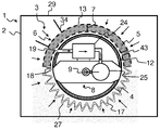
도 2는 더욱 예시적인 실시예의 장치의 평면도이고;
도 3은 모듈 및 장치를 구비한 자동차의 도면이고;
도 4는 파티클 스크린의 상세한 도면이고;
도 5는 클램핑 연결에 의해 파티클 스크린을 용기에 고정시키는 것을 나타낸 도면이고;
도 6은 멈춤쇠 부재에 의해 파티클 스크린을 용기에 고정시키는 것을 나타낸 도면이고;
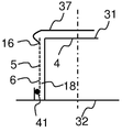
도 7은 클립 부재에 의한 파티클 스크린의 고정을 나타낸 도면이고;
도 8은 점착성 연결에 의해 파티클 스크린을 용기에 고정시키는 것을 나타낸 도면이고;
도 9는 다른 점착성 연결에 의한 파티클 스크린과 용기의 연결을 나타낸 도면이고;
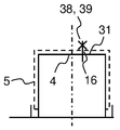
도 10은 나사와 리벳 연결에 의한 파티클 스크린과 용기의 연결을 나타낸 도면이고;
도 11은 나사산부에 의한 파티클 스크린과 용기의 연결을 나타낸 도면이고;
도 12는 클램핑 연결에 의해 파티클 스크린을 용기의 절결부에 고정하는 것을 나타낸 도면이며;
도 13은 도 12의 클램핑 연결의 다른 도면이다.1 is a side view of an apparatus in an exemplary embodiment;
2 is a plan view of the apparatus of a further exemplary embodiment;
Figure 3 is a view of a vehicle with a module and an apparatus;
4 is a detailed view of the particle screen;
5 is a view showing fixing of the particle screen to the container by clamping connection;
6 is a view showing fixing of the particle screen to the container by the detent member;
7 is a view showing fixing of a particle screen by a clip member;
8 is a view showing fixing of the particle screen to the container by sticky connection;
Figure 9 is a view showing the connection of the particle screen to the container by another viscous connection;
10 is a view showing connection of a particle screen and a container by screw and rivet connection;
11 is a view showing a connection between a particle screen and a container by a threaded portion;
12 is a view showing fixing of the particle screen to the notch portion of the container by clamping connection;
13 is another view of the clamping connection of Fig.
도 1은 예시적인 실시예의 장치(1) 개략적인 측면도이다. 장치는 용기(4)가 배치되는 내부 공간(3)을 갖는 탱크(2)를 포함한다. 환원제(15)를 탱크(2)로부터 인젝터(도시 생략)까지 이송시키기 위한 이송 유닛(8)이 용기(4)에 배치된다. 용기(4)는 파티클 스크린(5)에 의해, 그 원주방향 표면(26)에서 둘러싸인다. 1 is a schematic side view of an
파티클 스크린(5)은 또한 용기 상부면(31) 상을 뻗어있다. 파티클 스크린(5)은 스크린 외측 표면(6) 및 스크린 내측 표면(12)을 갖는다. 스크린 외측 표면(6) 및 스크린 내측 표면(12)은 깊이(7) 만큼 서로 이격되어 있다. 파티클 스크린(5)은 개구(13)를 구비하고, 그리고 상기 개구를 통해 환원제(15)가 탱크(2)의 내부 공간(3)으로부터, 여기에 도시된 중간 공간(18) 및 추출 개구나 리드쓰루(19)를 통해, 용기(4) 내의 이송 유닛(8)으로 통과한다. 파티클 스크린(5)은 또한 친수성 특성 및/또는 소수성 특성을 갖는 코팅(14)을 구비하여, 스크린 외측 표면(6)에 부착되는 파티클이 환원제(15)에 의해 흘러 나온다. 따라서 파티클 스크린(5)이 영구적으로 작동가능하도록, 상기 파티클 스크린(5)의 자동-세정 효과를 실현할 수 있다. The
탱크(2)는 탱크 벽부(29) 및 섬프(28, sump)를 탱크 베이스(33)의 구역에서 구비한다. 용기(4)는 섬프(28)의 구역에서 탱크 베이스(33)에 고정된다. 본 명세서에 개시된 예시적인 실시예에 있어서, 탱크 베이스(33)는 섬프(28)의 구역에서 탱크 개구(30)를 구비한다. 이러한 경우에, 용기(4)는 탱크 개구(30)를 통해 탱크(2)로 뻗어있다. 용기는 용기 베이스(32)를 구비한다. 이 경우, 이송 유닛(8)은 펌프(24), 압력 센서(25) 및 출발점(9)을 구비하고, 상기 출발점을 통해 환원제(15)가 환원제 이송 라인(도시 생략)으로 그리고 이후에 인젝터(도시 생략)로 이송된다. The
도 2는 더욱 예시적인 실시예의 장치(1)의 평면도이다. 환원제(15)는 탱크(2)의 내부 공간(3)으로부터 파티클 스크린(5)을 통하여 중간 공간(18)으로 이송되고, 그리고 상기 내부 공간으로부터 추출 개구 또는 리드쓰루(19)를 통해 이송 유닛(8)으로 이송된다. 이 경우, 환원제(15)는 중간 공간(18)으로부터 펌프(24)에 의해 이송 유닛(8)으로 이송된다. 환원제(15)는 펌프(24)로부터 압력 센서(25)를 통해 출발점(9)까지 통과한다. 환원제(15)는 개구(13)를 통해 파티클 스크린(5)의 덕트(43)로 통과하고, 그리고 스크린 내측 표면(12)에서 상기 파티클 스크린(5)의 외측으로 유동한다. 파티클 스크린(5)은 주름부(17)를 구비한다. 더욱이, 히터(27)는 파티클 스크린(5) 상에 배치되어, 상기 파티클 스크린(5)이 이에 따라 가열될 수 있어 얼려진 환원제(15)를 액화한다. 이 경우, 스크린 외측 표면으로부터 탱크 내부 공간(3)으로 뻗어있고 그리고 상기 내부 공간(3)에서 얼려진 환원제(15)의 해동을 허용하는 부재(34)가 파티클 스크린(5) 자체에 배치된다. 이를 위하여, 부재(34)가 히터(27)를 이와 같이 구비할 수 있거나, 또는 파티클 스크린(5)의 상기 히터(27)와 열-전도 연결 상태이다. 더욱이, 부재(34)는 환원제(15)의 평정(calming) 및 유지를 위해 사용된다. 이와 같이, 탱크(2) 가속의 경우에(예를 들면, 자동차 가속의 결과로서), 환원제(15)의 슬로싱이 방지될 수 있고, 더욱이 최소량의 환원제(15)가 파티클 스크린(5)의 구역에서 유지되어, 상기 파티클 스크린(5)의 개구(13)가 환원제(15)로 계속 충전된다. 2 is a plan view of the
도 3은 내연 기관(21)과 배기 시스템(22)을 구비한 자동차(20)를 도시한 도면이다. 인젝터(23)는 배기 시스템(22)에 또는 그 내부에 배치된다. 장치(1)에 의하여 환원제(15)가 인젝터(23)에 공급되어, 상기 환원제(15)가 상기 인젝터(23)를 통해 배기-가스 처리 목적의 배기 시스템(22)으로 이동될 수 있다. 이 경우, 장치(1) 및 인젝터(23)는 모듈(11)을 형성한다. 3 is a view showing an
도 4는 스크린 외측 표면(6)과 개구(13)를 갖는 파티클 스크린(5)의 상세한 도면이고, 상기 개구를 통해 환원제(15)가 탱크(2)의 내부(3)로부터 중간 공간(18)으로 진입한다. 개구(13)는 최대 직경(10)을 갖는다. 파티클 스크린과 같은 실시예 때문에, 최대 직경(10)보다 더 큰 직경을 갖는 파티클이 개구(13)를 통과하는 것이 방지되는 반면, 최대 직경(10)보다 더 작은 직경을 갖는 파티클이 상기 개구(13)를 통과하는데 실질적으로 방해받지 않는다. 따라서, 필터(기공 필터, 부직포, 패브릭, 니트(knit), 포옴 등)와 달리, 윤곽이 뚜렷한(clear-cut) 분리 효율이 실현된다. 상이한 크기의 파티클에 의한 파티클 스크린(5)의 연속의 막힘, 그리고 이에 따른 점진적인 폐색은 이에 따라 효과적인 방식으로 방지된다. 이 경우, 히터(27)는 스크린 외측 표면(6) 상에 배치된다. 상기 히터는 또한 파티클 스크린(5)에 또는 스크린 내측 표면(12) 상에 배치될 수 있다. 파티클 스크린(5)의 금속 실시예의 경우에 있어서, 또한 상기 파티클 스크린(5) 전체가 히터(27)로 실현될 수 있다. Figure 4 is a detailed view of a
도 5 내지 도 12는 용기(4)에 및/또는 탱크(2)에 파티클 스크린(5)을 고정시키는 상이한 고정 타입을 나타낸 도면이다. 도면에 도시된 연결 타입은 단지 특히 유리한 예시적인 실시예를 나타내고 있고, 여기서 당업자가 이처럼 본 발명으로 커버되는 이들 다른 연결 타입으로부터 유도할 수 있다. 따라서 본 발명은 특히 아래 도면에 도시된 예시적인 실시예로 한정되지 않는다. 5 to 12 are views showing different fixed types of fixing the
도 5는 점선으로 도시된 작은 파티클 스크린(5)이 장착된 용기(4)의 평면도이다. 파티클 스크린(5)은 보다 작은 직경을 갖거나 보다 작은 치수의 형태를 취하여, 용기(4) 상에 장착되도록 반드시 펼쳐져야 한다. 파티클 스크린(5)(외측, 실선)이 용기(4) 상에 장착되어 버린 이후에, 상기 파티클 스크린은 탄성적으로 변형되고 이에 따라 확대되어, 연결(16)이 클램핑에 의해 상기 용기(4)와 상기 파티클 스크린(5) 사이에 만들어진다. 5 is a plan view of the
도 6은 멈춤쇠 부재(36)에 의해 파티클 스크린(5)을 용기(4)에 고정시키는 것을 나타낸 도면이다. 파티클 스크린(5)은 이러한 목적을 위해 제공된 리세스(42)를 통해, 멈춤쇠 부재(36) 상에 장착된다. 멈춤쇠 부재(36)는 탄력적으로 변형가능한 상부 부분을 구비하고, 상기 변형가능한 상부 부분은 장착 공정 동안에 비교적 작은 리세스(42)에 의해 압축되고 그리고 상기 장착 공정 이후에 최초 형상으로 되돌아 온다. 따라서 연결(16)이 멈춤쇠 작동에 의해 구성요소 사이에 만들어진다. 6 is a view showing fixing of the
도 7은 클립 부재(37)가 용기 상부면(31) 상에 펼쳐져 있는 경우로서, 상기 클립 부재(37)에 의해, 용기(4)에 파티클 스크린(5)이 고정된 것을 나타낸 도면이다. 클립 부재(37)는 그 스크린 외측 표면(6)에서 파티클 스크린(5)을 둘러싸고, 이에 따라서 클램핑에 의해 연결(16)을 만든다. 이 경우, 시일(41)은 또한 파티클 스크린(5)과 용기 베이스(32) 사이에 도시되어 있다. 상기 시일(41)은 정화되지 않은 환원제(15)가 중간 공간(18)으로 진입하는 것을 방지한다. 상기 시일(41)은 이에 따라 본 발명에서 설명된 다른 예시적인 실시예에서 사용될 수 있다. 7 is a view showing that the
도 8은 점착성 연결(16)에 의해 파티클 스크린(5)을 용기(4)에 고정하는 것을 나타낸 도면이다. 이 경우, 파티클 스크린(5)은 중간 부분(35) 및 점착성 연결(16)을 통해, 예를 들면, 용접, 납땜 또는 점착성 본딩에 의해, 용기(4)에, 본 경우에서는 용기 상부면(31)에 고정된다. 파티클 스크린(5)은 중간 부분(35)의 재료로 부분적으로 끼워 넣어지거나(embed) 또는 상기 재료에 의해 감싸여진다. 이를 위하여, 중간 부분(35)은 주조에 의해 파티클 스크린(5)과 함께 만들어질 수 있다. 중간 부분(35)은 이에 따라 또한 파티클 스크린(5)의 배치 이후에 변형될 수 있다. 중간 부분(35)과 관련하여 행해진 사항이 이에 따라 용기(4)에 적용되며, 달리 말하자면 이에 따라 용기(4)는 또한 파티클 스크린(5)과 직접적으로 연결될 수 있다. 8 is a view showing fixing of the
도 9는 롤 심 용접에 의한 파티클 스크린(5)과 용기(4) 사이의 연결(16)을 나타낸 도면이다. 9 is a view showing a
도 10은 용기 상부면(31) 상에 배치된, 나사(38) 또는 리벳(39)에 의한 파티클 스크린(5)과 용기(4) 사이의 연결(16)을 나타낸 도면이다. 도 11은 용기 베이스(32)의 구역에 배치된 나사산부(40)에 의한 경우로서, 파티클 스크린(5)과 용기(4)의 연결(16)을 나타낸 도면이다. 파티클 스크린(5) 및 용기(4)나 또는 용기 베이스(32)의 각각의 한 부분이 나사산부(40)를 구비하여, 상기 파티클 스크린(5)이 상기 파티클 스크린(5) 자체의 회전에 의해, 상기 용기(4) 상에 배치된 상기 나사산부(40)로 나사결합될 수 있거나 또는, 여기에 도시된 바와 같이 상기 용기 베이스(32)로 나사결합될 수 있다. 10 is a view showing a
도 12는 용기(4)의 평면도이다. 용기(4)와 파티클 스크린(5)의 연결(16)은 도 5에 따른 실시예에서와 같이, 클램핑에 의해 발생된다. 파티클 스크린(5)은 용기와 관련하여 보강되고, 특히 상기 용기(4)의 절결부(44, cutout)에 클램프된다. 12 is a plan view of the
초음파 센서(45)가 절결부(44)에 배치되며 상기 초음파 센서에 의해 환원제 탱크에서의 충전 레벨이 모니터될 수 있다. 초음파 센서(45)는 상부로부터 용기(4)에 의해 커버되지 않는다. The
도 12에 도시된 용기(4)는 도 13에서와 다른 시점으로 도시되어 있다. 상기 도면에서 파티클 스크린(5)이 클램프되는 절결부(44)를 볼 수 있다. The
초음파 센서(45)는 절결부(44)에 위치된다. 점선은 충전 레벨을 모니터링하기 위한 목적으로서, 초음파 센서(45)로부터 상향으로 뻗어있는 초음파 빔을 나타낸다. 초음파(45)는 절결부(44)에 배치되어, 상향 방향으로 자유롭게 되고 용기(4)의 구역에 의해 커버되지 않는다. The
본 발명은 가능한 간단하고 비용이 많이 들지 않는 파티클 스크린의 설계품을 제안한다. 파티클 스크린의 폐색은 비교적 오랜 시간 간격 동안에 방지될 수 있다. 더욱이, 파티클 스크린의 자동 세정 효과가 사용될 수 있어, 환원제로부터 펌프 및/또는 도우징 유닛(dosing unit)까지 파티클의 유지를 위한 모든 구성요소가 실질적으로 유지보수를 필요로 하지 않는다. 금속의 실시예 때문에, 파티클 스크린 자체는 또한 히터로 사용될 수 있다. 이에 따라 환원제는 파티클 스크린으로부터 진행부 외측으로 성공적으로 해동된다. The present invention proposes a design of a particle screen that is as simple and cost-effective as possible. Clogging of the particle screen can be prevented for a relatively long time interval. Moreover, the automatic cleaning effect of the particle screen can be used, so that all components for the maintenance of the particles from the reducing agent to the pump and / or the dosing unit do not require substantial maintenance. Because of the embodiment of the metal, the particle screen itself can also be used as a heater. As a result, the reducing agent is successfully thawed from the particle screen to the outside of the advancement.
1 장치 2 탱크
3 내부 4 용기
5 파티클 스크린 6 스크린 외측 표면
7 깊이 8 이송 유닛
9 출발점 10 최대 직경
11 모듈 12 스크린 내측 표면
13 개구 14 코팅
15 환원제 16 연결
17 주름부 18 중간 공간
19 추출 개구/리드쓰루 20 자동차
21 내연기관 22 배기 시스템
23 인젝터 24 펌프
25 압력 센서 26 원주방향 표면
27 히터 28 섬프
29 탱크 벽부 30 탱크 개구
31 용기 상부면 32 용기 베이스
33 탱크 베이스 34 부재
35 중간 부분 36 멈춤쇠 부재
37 클립 부재 38 나사
39 리벳 40 나사산부
41 시일 42 리세스
43 덕트 44 절결부
45 초음파 센서1
3 internal 4 containers
5
7 Depth 8 Transfer Unit
9 Starting
11
13
15
17
19 Extraction aperture / lead-through 20 cars
21
23
25
27 Heater 28 Sump
29
31
33
35
37 Clip member 38 Screw
39
41
43
45 Ultrasonic sensor
Claims (10)
상기 용기(4)는, 유동이 통과할 수 있는 파티클 스크린(5)에 의해, 상기 용기의 상측과 주변 표면 모두 둘러싸이고, 그리고 상기 용기(4)에 이송 유닛(8)이 위치되고, 상기 이송 유닛은 환원제를 상기 탱크(2)로부터 상기 파티클 스크린(5)을 통해, 이후 환원제(15)용 출발점(9)까지 이송하도록 셋업되고, 상기 파티클 스크린(5)은 주름부(17)를 구비하고, 환원제의 관통 유동을 위해 동일하게 치수 형성된 개구를 구비하고, 상기 스크린의 지지를 위한 지지 구조체가 요구되지 않도록 강성을 갖는, 용기(4)를 구비한 장치(1). (4) at least partially disposed in the internal space (3) of the tank (2), comprising a tank (2) having an internal space (3) (1)
The container 4 is surrounded by a particle screen 5 through which the flow can pass and both the upper and the peripheral surfaces of the container and the transfer unit 8 is located in the container 4, Unit is set up to transport a reducing agent from the tank 2 through the particle screen 5 and then to a starting point 9 for the reducing agent 15 and the particle screen 5 has a corrugation 17 (1) having a container (4) having an opening that is dimensioned identically for through flow of a reducing agent, and which is rigid so that a support structure for supporting the screen is not required.
각각의 개구(13)가 많아야 50 ㎛의 최대 직경(10)을 갖는, 용기(4)를 구비한 장치(1). The method according to claim 1,
A device (1) with a container (4), wherein each opening (13) has a maximum diameter (10) of at most 50 탆.
상기 파티클 스크린(5)은 적어도 하나의 와이어 메쉬이거나 또는 포일을 포함하는, 용기(4)를 구비한 장치(1). The method according to claim 1 or 3,
Wherein the particle screen (5) is at least one wire mesh or comprises a foil (1).
스크린 외측 표면(6)으로부터 스크린 내측 표면(12) 쪽으로 보다 작게 나아가도록 개구(13)가 형성되는, 용기(4)를 구비한 장치(1). The method according to claim 1 or 3,
Wherein the opening (13) is formed to be smaller than the screen outer surface (6) toward the screen inner surface (12).
상기 파티클 스크린(5)은 많아야 0.5 mm의 스크린 내측 표면(12)과 스크린 외측 표면(6) 사이에 깊이(7)를 갖는, 용기(4)를 구비한 장치(1). The method according to claim 1 or 3,
Wherein the particle screen (5) has a depth (7) between the screen inner surface (12) and the screen outer surface (6) of at most 0.5 mm.
상기 파티클 스크린(5)은 작동 동안에 자동-세정되는, 용기(4)를 구비한 장치(1). The method according to claim 1 or 3,
The particle screen (5) is auto-cleaned during operation, the device (1) comprising a container (4).
적어도 상기 스크린 외측 표면(6)은 적어도 부분적으로 소수성이나 친수성 특성(14)을 갖는, 용기(4)를 구비한 장치(1). The method according to claim 1 or 3,
At least the screen outer surface (6) at least partially having hydrophobic or hydrophilic properties (14).
상기 파티클 스크린(5)은:
a) 클램핑, 프레싱 및 브레이싱(bracing)과 같은 방법 중 적어도 하나의 방법에 의한 연결(16);
b) 점착성 연결(16);
c) 적어도 부분적으로 감싸여짐;
d) 나사산부(40)에 의한 연결(16)과 같은 고정 타입 중 적어도 하나의 타입에 의해 상기 용기(4)나 또는 상기 탱크(2)에 연결되는, 용기(4)를 구비한 장치(1). The method according to claim 1 or 3,
The particle screen (5) comprises:
a) a connection (16) by at least one of the following methods: clamping, pressing and bracing;
b) viscous connection (16);
c) at least partially wrapped;
(1) with a container (4) connected to the container (4) or to the tank (2) by at least one type of fixed type, such as a connection ).
Applications Claiming Priority (3)
| Application Number | Priority Date | Filing Date | Title |
|---|---|---|---|
| DE201110112326 DE102011112326A1 (en) | 2011-09-02 | 2011-09-02 | Device for providing liquid reducing agent with a particle sieve |
| DE102011112326.5 | 2011-09-02 | ||
| PCT/EP2012/066365 WO2013030067A1 (en) | 2011-09-02 | 2012-08-22 | Device for providing a liquid reducing agent having a particle filter |
Publications (2)
| Publication Number | Publication Date |
|---|---|
| KR20140046043A KR20140046043A (en) | 2014-04-17 |
| KR101676929B1 true KR101676929B1 (en) | 2016-11-17 |
Family
ID=46724430
Family Applications (1)
| Application Number | Title | Priority Date | Filing Date |
|---|---|---|---|
| KR1020147005830A Active KR101676929B1 (en) | 2011-09-02 | 2012-08-22 | Device for Providing a Liquid Reducing Agent Having a Particle Filter |
Country Status (8)
| Country | Link |
|---|---|
| US (1) | US9121324B2 (en) |
| EP (1) | EP2751402A1 (en) |
| JP (1) | JP2014525541A (en) |
| KR (1) | KR101676929B1 (en) |
| CN (1) | CN103764962B (en) |
| DE (1) | DE102011112326A1 (en) |
| RU (1) | RU2607578C2 (en) |
| WO (1) | WO2013030067A1 (en) |
Families Citing this family (11)
| Publication number | Priority date | Publication date | Assignee | Title |
|---|---|---|---|---|
| EP2848931A1 (en) * | 2013-09-16 | 2015-03-18 | Inergy Automotive Systems Research (Société Anonyme) | A vehicle urea tank associated with a sensing chamber for acoustic quality and level sensing |
| DE102014000643A1 (en) * | 2013-07-26 | 2015-01-29 | Tesona Gmbh & Co. Kg | Device for receiving and providing liquid reducing agent |
| DE202013010565U1 (en) * | 2013-11-22 | 2014-11-24 | Seuffer gmbH & Co. KG | Tank module for a liquid tank |
| DE102014103715A1 (en) * | 2014-03-19 | 2015-09-24 | Emitec France S.A.S | Liquid cleaning element for cleaning a liquid |
| CN204186452U (en) * | 2014-06-27 | 2015-03-04 | 康明斯排放处理公司 | Reducing agent feeding mechanism and reductant supply system and engine system |
| US9465000B1 (en) | 2015-08-18 | 2016-10-11 | Intellectual Reserves, LLC | System and method for electronically determining fluid parameters |
| DE102017200277A1 (en) | 2017-01-10 | 2018-07-12 | Robert Bosch Gmbh | Level sensor for detecting a level of a liquid |
| EP3415733A1 (en) * | 2017-06-14 | 2018-12-19 | MEAS France | Fluid quality sensor for measuring the quality of a fluid, sensor assembly and assembly for combustion engines comprising a fluid quality sensor |
| DE102018005828A1 (en) | 2018-07-25 | 2019-01-03 | Daimler Ag | Tank for a motor vehicle |
| CN113027554B (en) * | 2021-03-15 | 2022-10-11 | 西安西热节能技术有限公司 | Inlet structure of drainage cooling section of dual-channel heater and design method |
| CN120827766B (en) * | 2025-09-19 | 2025-11-21 | 沈阳博宇科技有限责任公司 | An online slag removal system for circulating slurry in desulfurization processes |
Citations (3)
| Publication number | Priority date | Publication date | Assignee | Title |
|---|---|---|---|---|
| JP2003019411A (en) | 2001-07-10 | 2003-01-21 | Mitsui Eng & Shipbuild Co Ltd | Particulate matter removal filter and method of manufacturing the same |
| DE102009029400A1 (en) | 2009-09-11 | 2011-03-24 | Robert Bosch Gmbh | Fuel tank for storing liquid, has main tank, inner tank and conveying device for conveying stored fluid from tank volume |
| WO2011085830A1 (en) | 2010-01-13 | 2011-07-21 | Emitec Gesellschaft Für Emissionstechnologie Mbh | Tank assembly and metering system for a reducing agent |
Family Cites Families (21)
| Publication number | Priority date | Publication date | Assignee | Title |
|---|---|---|---|---|
| DE19521509A1 (en) * | 1995-06-13 | 1996-12-19 | Bosch Gmbh Robert | Device for delivering fuel from a storage tank to an internal combustion engine |
| DE19619992A1 (en) * | 1996-05-17 | 1997-11-20 | Bosch Gmbh Robert | Fuel-feed module including coarse and fine filters and storage tube |
| DE19936287C2 (en) * | 1999-08-02 | 2003-04-30 | Bosch Gmbh Robert | Demand control for a fuel delivery module with variable system pressure |
| JP2003126619A (en) * | 2001-10-29 | 2003-05-07 | Kyosan Denki Co Ltd | Fuel filter |
| DE10308287B4 (en) | 2003-02-26 | 2006-11-30 | Umicore Ag & Co. Kg | Process for exhaust gas purification |
| WO2004082804A1 (en) * | 2003-03-21 | 2004-09-30 | Mann+Hummel Gmbh | Fuel filtering system |
| JP4302458B2 (en) * | 2003-07-31 | 2009-07-29 | 株式会社ニフコ | Fuel filter device |
| DE102004051746A1 (en) | 2004-10-23 | 2006-04-27 | Robert Bosch Gmbh | Tank module for a reducing agent and dosing system |
| JP2007069747A (en) * | 2005-09-07 | 2007-03-22 | Toyota Motor Corp | Fuel tank equipment |
| DE102006027487A1 (en) * | 2005-09-12 | 2007-03-15 | Robert Bosch Gmbh | Vehicle tank for a liquid reducing agent, in particular for a urea solution |
| JP4785576B2 (en) * | 2006-03-17 | 2011-10-05 | 株式会社ケーヒン | Fuel supply system for motorcycles |
| JP2007315255A (en) * | 2006-05-24 | 2007-12-06 | Toyota Industries Corp | Fuel supply system |
| DE102006050807A1 (en) * | 2006-10-27 | 2008-04-30 | Robert Bosch Gmbh | Catalytic reduction device |
| DE102007047885A1 (en) * | 2006-11-29 | 2008-06-05 | Denso Corp., Kariya | Reductive pressure feed pump for use in reducing agent utility system, has drive section producing drive power for driving mechanical section to discharge pressure to reducing agent, which flows through flow path over drive section |
| JP2008291678A (en) * | 2007-05-22 | 2008-12-04 | Denso Corp | Reducing agent feeding apparatus |
| FR2918576B1 (en) | 2007-07-10 | 2009-10-09 | Inergy Automotive Systems Res | LIQUID SUPPLY SYSTEM FOR VEHICLE AND INTEGRATED PUMP / FILTER MODULE. |
| FR2918718B1 (en) * | 2007-07-10 | 2013-06-28 | Inergy Automotive Systems Res | ROTARY PUMP FOR VEHICLE. |
| CN101660443B (en) * | 2008-05-28 | 2011-08-10 | 中国第一汽车集团公司 | Vehicle-mounted SCR metering and ejecting system taking exhaust gas temperature as variable |
| DE102009041179A1 (en) * | 2009-09-11 | 2011-03-24 | Emitec Gesellschaft Für Emissionstechnologie Mbh | Delivery device for a reducing agent |
| DE102010014314A1 (en) | 2010-04-09 | 2011-10-13 | Emitec Gesellschaft Für Emissionstechnologie Mbh | Device for providing liquid reducing agent |
| DE102010024554B4 (en) | 2010-06-22 | 2015-04-02 | Seuffer gmbH & Co. KG | Tank module for a liquid tank |
-
2011
- 2011-09-02 DE DE201110112326 patent/DE102011112326A1/en active Pending
-
2012
- 2012-08-22 WO PCT/EP2012/066365 patent/WO2013030067A1/en not_active Ceased
- 2012-08-22 EP EP12750594.9A patent/EP2751402A1/en not_active Withdrawn
- 2012-08-22 RU RU2014112503A patent/RU2607578C2/en active
- 2012-08-22 KR KR1020147005830A patent/KR101676929B1/en active Active
- 2012-08-22 CN CN201280042842.2A patent/CN103764962B/en active Active
- 2012-08-22 JP JP2014527589A patent/JP2014525541A/en active Pending
-
2014
- 2014-03-03 US US14/194,970 patent/US9121324B2/en active Active
Patent Citations (3)
| Publication number | Priority date | Publication date | Assignee | Title |
|---|---|---|---|---|
| JP2003019411A (en) | 2001-07-10 | 2003-01-21 | Mitsui Eng & Shipbuild Co Ltd | Particulate matter removal filter and method of manufacturing the same |
| DE102009029400A1 (en) | 2009-09-11 | 2011-03-24 | Robert Bosch Gmbh | Fuel tank for storing liquid, has main tank, inner tank and conveying device for conveying stored fluid from tank volume |
| WO2011085830A1 (en) | 2010-01-13 | 2011-07-21 | Emitec Gesellschaft Für Emissionstechnologie Mbh | Tank assembly and metering system for a reducing agent |
Also Published As
| Publication number | Publication date |
|---|---|
| DE102011112326A1 (en) | 2013-03-07 |
| US9121324B2 (en) | 2015-09-01 |
| JP2014525541A (en) | 2014-09-29 |
| CN103764962B (en) | 2016-08-17 |
| CN103764962A (en) | 2014-04-30 |
| US20140178266A1 (en) | 2014-06-26 |
| RU2014112503A (en) | 2015-10-10 |
| KR20140046043A (en) | 2014-04-17 |
| EP2751402A1 (en) | 2014-07-09 |
| RU2607578C2 (en) | 2017-01-10 |
| WO2013030067A1 (en) | 2013-03-07 |
Similar Documents
| Publication | Publication Date | Title |
|---|---|---|
| KR101676929B1 (en) | Device for Providing a Liquid Reducing Agent Having a Particle Filter | |
| JP5886270B2 (en) | Apparatus for providing a liquid reducing agent | |
| RU2496994C2 (en) | Device for feeding reducing agent and method for producing vehicle | |
| US10018090B2 (en) | Filter cartridge for a reducing agent delivery device and delivery device and motor vehicle having a filter cartridge | |
| JP6092872B2 (en) | Device for supplying liquid reducing agent | |
| JP4894827B2 (en) | Reducing agent supply system | |
| JP2015500415A (en) | Equipment for supplying reducing agent | |
| CN103261608B (en) | Liquid removal module, liquid tank for removing liquid from a liquid tank | |
| US10286341B2 (en) | Liquid purification element for purifying a liquid | |
| RU2620899C2 (en) | Device for feeding liquid additive | |
| US20160010526A1 (en) | Method for extracting a liquid additive from a tank | |
| RU2674823C1 (en) | Element for cleaning liquids |
Legal Events
| Date | Code | Title | Description |
|---|---|---|---|
| A201 | Request for examination | ||
| PA0105 | International application |
St.27 status event code: A-0-1-A10-A15-nap-PA0105 |
|
| PA0201 | Request for examination |
St.27 status event code: A-1-2-D10-D11-exm-PA0201 |
|
| PG1501 | Laying open of application |
St.27 status event code: A-1-1-Q10-Q12-nap-PG1501 |
|
| E902 | Notification of reason for refusal | ||
| PE0902 | Notice of grounds for rejection |
St.27 status event code: A-1-2-D10-D21-exm-PE0902 |
|
| E13-X000 | Pre-grant limitation requested |
St.27 status event code: A-2-3-E10-E13-lim-X000 |
|
| P11-X000 | Amendment of application requested |
St.27 status event code: A-2-2-P10-P11-nap-X000 |
|
| P13-X000 | Application amended |
St.27 status event code: A-2-2-P10-P13-nap-X000 |
|
| E14-X000 | Pre-grant third party observation filed |
St.27 status event code: A-2-3-E10-E14-opp-X000 |
|
| E902 | Notification of reason for refusal | ||
| PE0902 | Notice of grounds for rejection |
St.27 status event code: A-1-2-D10-D21-exm-PE0902 |
|
| PN2301 | Change of applicant |
St.27 status event code: A-3-3-R10-R13-asn-PN2301 St.27 status event code: A-3-3-R10-R11-asn-PN2301 |
|
| T11-X000 | Administrative time limit extension requested |
St.27 status event code: U-3-3-T10-T11-oth-X000 |
|
| T11-X000 | Administrative time limit extension requested |
St.27 status event code: U-3-3-T10-T11-oth-X000 |
|
| T11-X000 | Administrative time limit extension requested |
St.27 status event code: U-3-3-T10-T11-oth-X000 |
|
| T11-X000 | Administrative time limit extension requested |
St.27 status event code: U-3-3-T10-T11-oth-X000 |
|
| P11-X000 | Amendment of application requested |
St.27 status event code: A-2-2-P10-P11-nap-X000 |
|
| P13-X000 | Application amended |
St.27 status event code: A-2-2-P10-P13-nap-X000 |
|
| E90F | Notification of reason for final refusal | ||
| PE0902 | Notice of grounds for rejection |
St.27 status event code: A-1-2-D10-D21-exm-PE0902 |
|
| T11-X000 | Administrative time limit extension requested |
St.27 status event code: U-3-3-T10-T11-oth-X000 |
|
| E13-X000 | Pre-grant limitation requested |
St.27 status event code: A-2-3-E10-E13-lim-X000 |
|
| P11-X000 | Amendment of application requested |
St.27 status event code: A-2-2-P10-P11-nap-X000 |
|
| P13-X000 | Application amended |
St.27 status event code: A-2-2-P10-P13-nap-X000 |
|
| E701 | Decision to grant or registration of patent right | ||
| PE0701 | Decision of registration |
St.27 status event code: A-1-2-D10-D22-exm-PE0701 |
|
| GRNT | Written decision to grant | ||
| PR0701 | Registration of establishment |
St.27 status event code: A-2-4-F10-F11-exm-PR0701 |
|
| PR1002 | Payment of registration fee |
St.27 status event code: A-2-2-U10-U12-oth-PR1002 Fee payment year number: 1 |
|
| PG1601 | Publication of registration |
St.27 status event code: A-4-4-Q10-Q13-nap-PG1601 |
|
| R18-X000 | Changes to party contact information recorded |
St.27 status event code: A-5-5-R10-R18-oth-X000 |
|
| FPAY | Annual fee payment |
Payment date: 20191031 Year of fee payment: 4 |
|
| PR1001 | Payment of annual fee |
St.27 status event code: A-4-4-U10-U11-oth-PR1001 Fee payment year number: 4 |
|
| FPAY | Annual fee payment |
Payment date: 20201030 Year of fee payment: 5 |
|
| PR1001 | Payment of annual fee |
St.27 status event code: A-4-4-U10-U11-oth-PR1001 Fee payment year number: 5 |
|
| FPAY | Annual fee payment |
Payment date: 20211028 Year of fee payment: 6 |
|
| PR1001 | Payment of annual fee |
St.27 status event code: A-4-4-U10-U11-oth-PR1001 Fee payment year number: 6 |
|
| PN2301 | Change of applicant |
St.27 status event code: A-5-5-R10-R13-asn-PN2301 St.27 status event code: A-5-5-R10-R11-asn-PN2301 |
|
| FPAY | Annual fee payment |
Payment date: 20221028 Year of fee payment: 7 |
|
| PR1001 | Payment of annual fee |
St.27 status event code: A-4-4-U10-U11-oth-PR1001 Fee payment year number: 7 |
|
| PN2301 | Change of applicant |
St.27 status event code: A-5-5-R10-R11-asn-PN2301 |
|
| PN2301 | Change of applicant |
St.27 status event code: A-5-5-R10-R14-asn-PN2301 |
|
| PR1001 | Payment of annual fee |
St.27 status event code: A-4-4-U10-U11-oth-PR1001 Fee payment year number: 8 |
|
| PR1001 | Payment of annual fee |
St.27 status event code: A-4-4-U10-U11-oth-PR1001 Fee payment year number: 9 |
|
| PR1001 | Payment of annual fee |
St.27 status event code: A-4-4-U10-U11-oth-PR1001 Fee payment year number: 10 |
|
| U11 | Full renewal or maintenance fee paid |
Free format text: ST27 STATUS EVENT CODE: A-4-4-U10-U11-OTH-PR1001 (AS PROVIDED BY THE NATIONAL OFFICE) Year of fee payment: 10 |