KR101634642B1 - Touch sensing device, touch sensing circuit, data driving circuit, and driving display device driving method - Google Patents
Touch sensing device, touch sensing circuit, data driving circuit, and driving display device driving method Download PDFInfo
- Publication number
- KR101634642B1 KR101634642B1 KR1020150136677A KR20150136677A KR101634642B1 KR 101634642 B1 KR101634642 B1 KR 101634642B1 KR 1020150136677 A KR1020150136677 A KR 1020150136677A KR 20150136677 A KR20150136677 A KR 20150136677A KR 101634642 B1 KR101634642 B1 KR 101634642B1
- Authority
- KR
- South Korea
- Prior art keywords
- driving
- touch
- sensing
- signal
- period
- Prior art date
- Legal status (The legal status is an assumption and is not a legal conclusion. Google has not performed a legal analysis and makes no representation as to the accuracy of the status listed.)
- Active
Links
Images


Classifications
-
- G—PHYSICS
- G06—COMPUTING OR CALCULATING; COUNTING
- G06F—ELECTRIC DIGITAL DATA PROCESSING
- G06F3/00—Input arrangements for transferring data to be processed into a form capable of being handled by the computer; Output arrangements for transferring data from processing unit to output unit, e.g. interface arrangements
- G06F3/01—Input arrangements or combined input and output arrangements for interaction between user and computer
- G06F3/03—Arrangements for converting the position or the displacement of a member into a coded form
- G06F3/041—Digitisers, e.g. for touch screens or touch pads, characterised by the transducing means
- G06F3/0416—Control or interface arrangements specially adapted for digitisers
Landscapes
- Engineering & Computer Science (AREA)
- Control Of Indicators Other Than Cathode Ray Tubes (AREA)
- General Engineering & Computer Science (AREA)
- Theoretical Computer Science (AREA)
- Human Computer Interaction (AREA)
- Physics & Mathematics (AREA)
- General Physics & Mathematics (AREA)
Abstract
본 발명은 핑거모드와 호버 모드에 따라 서로 상이한 센싱 영역들이 활성화되도록 하고, 특히, 센싱 영역에 대한 비접촉에서의 센싱 구동을 의미하는 호버 모드에서 가능한 많은 센싱 영역들이 동시에 활성화됨으로써, 센싱 감도가 강화되어 호버 모드에서도 센싱 검출 성능이 증대시킬 수 있는 터치 센싱 장치, 터치 센싱 회로, 데이터 구동회로 및 표시장치의 구동 방법에 관한 것이다. In the present invention, different sensing regions are activated according to the finger mode and the hover mode, and in particular, as many sensing regions as possible are simultaneously activated in the hover mode, which means sensing driving in a non-contact manner with respect to the sensing region, To a touch sensing device, a touch sensing circuit, a data driving circuit, and a driving method of a display device, which can increase sensing detection performance even in a hover mode.
Description
본 발명은 터치 센싱 장치, 터치 센싱 회로, 데이터 구동 회로 및 표시장치의 구동방법에 관한 것이다.The present invention relates to a touch sensing device, a touch sensing circuit, a data driving circuit, and a driving method of the display device.
최근 들어, 터치 기능이 표시패널에 구비된 터치 센서에 의해 다양한 유저 인터페이스(User Interface, UI)의 구현이 가능하다. 터치 세서가 포함된 표시패널은 터치에 의한 입력 기능과 정보의 출력 기능이 모두 가능한 입출력 수단이다.In recent years, a variety of user interfaces (UI) can be implemented by a touch sensor provided with a touch function on a display panel. A display panel including a touch sensor is an input / output means capable of both a touch input function and an information output function.
정전 용량 방식의 터치 기능을 갖는 표시패널은 기존의 저항막 방식에 비하여 내구성과 선명도가 높고, 멀티 터치 인식과 근접 터치 인식이 가능하여 다양한 어플리케이션에 적용될 수 있는 장점이 있다.The display panel having the touch function of the capacitive touch screen has advantages such as durability and sharpness compared to the conventional resistive touch screen, multi-touch recognition and proximity touch recognition, and is applicable to various applications.
정전 용량 방식의 터치 기능을 갖는 표시패널은 터치센서를 포함하는 기판이 표시패널 상에 접착되거나 터치센서가 표시패널에 내장(인셀 타입)되므로 표시소자와 전기적으로 커플링되어 있다. A display panel having a capacitive touch function is electrically coupled to a display element because a substrate including the touch sensor is bonded to the display panel or a touch sensor is embedded in the display panel (in-cell type).
최근의 터치 기능을 갖는 표시패널은 핑거 모드(finger mode)와 같은 접촉 터치 모드에서뿐만 아니라 호버 모드(hover mode) 또는 근접 터치 모드 등의 비접촉 터치 모드에서도 터치 인식이 되도록 연구되고 있다. 접촉 터치 모드라 함은 표시패널에서 포인터가 접촉하는 직접적인 터치를 인식 가능하도록 하는 기능이다. 비접촉 터치 모드라 함은 표시패널에 포인터가 직접 접촉하지 않고, 표시패널에 가깝게 근접한 근접(proximity) 터치 또는 표시패널과 이격된 이격(hovering) 터치를 인식 가능하도록 함을 의미한다. Recently, a display panel having a touch function has been studied not only in a touch mode such as a finger mode but also in a non-contact touch mode such as a hover mode or a proximity touch mode. The touch-on-touch mode is a function that enables a direct touch in which the pointer touches the display panel to be recognized. The non-contact touch mode means that a pointer is not directly contacted with the display panel, but a proximity touch closely adjacent to the display panel or a hovering touch apart from the display panel can be recognized.
이 중 인셀 타입의 터치 센서들을 포함하는 표시패널에 대한 호버 모드에서의 터치 기능은 아직 구현되지 않고 있다.Among them, the touch function in the hover mode for the display panel including the in-cell type touch sensors is not yet implemented.
본 발명은 전술한 문제 및 다른 문제를 해결하는 것을 목적으로 한다.The present invention is directed to solving the above-mentioned problems and other problems.
본 발명의 다른 목적은 인셀 타입의 터치 센서들을 포함하는 표시패널에서 터치 인지 감도가 우수한 감도를 유지하여 호버 모드에서의 터치 인지가 가능하도록 하는 터치 센싱 장치를 제공하는 데 있다.It is another object of the present invention to provide a touch sensing device for enabling a touch in a hover mode to be maintained in a display panel including an in-cell type touch sensor while maintaining a high sensitivity with respect to touch sensitivity.
본 발명의 또 다른 목적은, 접촉 터치 및 비접촉 터치 각각에 적합한 터치 구동을 할 수 있는 터치 센싱 장치, 터치 센싱 회로, 데이터 구동회로 및 표시장치의 구동방법을 제공하는데 있다. It is still another object of the present invention to provide a touch sensing device, a touch sensing circuit, a data driving circuit, and a driving method of a display device that can perform touch driving suited to each of a contact touch and a non-contact touch.
일 측면에서, 본 발명은, 다수의 터치 센서를 포함하는 표시패널과, 다수의 터치 센서로 터치 인지를 위한 구동신호를 공급하고, 다수의 터치 센서를 통해 센싱신호를 검출하는 센싱신호 검출부과, 접촉 터치 구동인 경우와 비접촉 터치 구동인 경우에 대하여 상이한 개수의 터치 센서를 센싱신호 검출부에 전기적으로 연결해주는 선택회로를 포함하되, 비접촉 터치 구동인 경우 다수의 터치 센서로 공급되는 구동 신호는, 접촉 터치 구동인 경우 다수의 터치 센서로 공급되는 구동 신호에 비해 큰 신호 세기를 갖는 터치 센싱 장치를 제공할 수 있다. According to an aspect of the present invention, there is provided a display device including a display panel including a plurality of touch sensors, a sensing signal detecting unit for supplying a driving signal for touch recognition with a plurality of touch sensors and detecting a sensing signal through a plurality of touch sensors, And a selection circuit for electrically connecting a different number of touch sensors to the sensing signal detection unit in case of contact touch driving and non-contact touch driving, wherein the driving signal supplied to the plurality of touch sensors in the non- It is possible to provide a touch sensing apparatus having a larger signal intensity than a driving signal supplied to a plurality of touch sensors in the case of touch driving.
다른 측면에서, 본 발명은, 다수의 터치 센서에 인가될 구동 신호를 순차적으로 출력하고, 다수의 터치 센서를 통해 센싱신호를 검출하는 센싱신호 검출부와, 접촉 터치 구동인 경우와 비접촉 터치 구동인 경우에 대하여 상이한 개수의 터치 센서를 센싱신호 검출부에 전기적으로 연결해주는 선택회로를 포함하되, 비접촉 터치 구동인 경우 출력되는 구동 신호는, 접촉 터치 구동인 경우 출력되는 구동 신호에 비해 큰 신호 세기를 갖는 터치 센싱 회로를 제공할 수 있다. According to another aspect of the present invention, there is provided a touch sensing device including: a sensing signal detecting unit sequentially outputting a driving signal to be applied to a plurality of touch sensors and detecting a sensing signal through a plurality of touch sensors; And a selection circuit for electrically connecting a different number of touch sensors to the sensing signal detecting unit in response to the touch signal, wherein the driving signal output in the case of the non-contact touch driving is a touch signal having a larger signal intensity A sensing circuit can be provided.
또 다른 측면에서, 본 발명은, 표시패널에 배치된 다수의 터치 센서와 전기적으로 연결되며, 터치 구동 모드 시, 다수의 터치 센서로 구동 신호를 순차적으로 공급하되, 접촉 터치 구동인 경우, 임의의 한 타이밍에 하나의 터치 센서로 구동 신호를 공급하고, 비접촉 터치 구동인 경우, 임의의 한 타이밍에 둘 이상의 터치 센서로 구동 신호를 공급하되, 비접촉 터치 구동인 경우의 구동 신호는 오버 드라이빙 구간을 갖는 터치 센싱 회로를 제공할 수 있다. According to another aspect of the present invention, there is provided a touch panel device comprising: a touch panel; a plurality of touch sensors disposed on a display panel; And the driving signal is supplied to at least one of the touch sensors at an arbitrary timing, and the driving signal in the case of noncontact touch driving is supplied with a driving signal having an overdriving period A touch sensing circuit can be provided.
또 다른 측면에서, 본 발명은, 다수의 센싱 라인을 통해 표시패널에 배치된 다수의 터치 센서와 전기적으로 연결되며, 터치 구동 모드 시, 다수의 터치 센서로 구동 신호를 순차적으로 공급하되, 임의의 한 타이밍에 둘 이상의 터치 센서로 오버 드라이빙 구간을 갖는 구동 신호를 함께 공급하는 터치 센싱 회로를 제공할 수 있다. According to another aspect of the present invention, there is provided a touch sensing device including: a plurality of touch sensors electrically connected to a plurality of touch sensors disposed on a display panel through a plurality of sensing lines, sequentially supplying driving signals to a plurality of touch sensors in a touch driving mode, It is possible to provide a touch sensing circuit that simultaneously supplies a drive signal having an overdriving section with two or more touch sensors at a timing.
또 다른 측면에서, 본 발명은, 표시패널에 배치된 다수의 터치 센서와 전기적으로 연결되며, 터치 구동 시, 다수의 터치 센서로 구동 신호를 순차적으로 공급하여 터치 유무를 검출하되, 접촉 터치 구동인 경우, 하나의 터치 센서에 해당하는 센싱 영역 단위로 터치 유무를 검출하고, 비접촉 터치 구동인 경우, 둘 이상의 터치 센서에 해당하는 블록 단위로 터치 유무를 검출하고, 비접촉 터치 구동인 경우, 접촉 터치 구동인 경우에 비해, 큰 신호 세기를 갖는 구동 신호를 공급하는 터치 센싱 회로를 제공할 수 있다. According to another aspect of the present invention, there is provided a touch panel including a plurality of touch sensors electrically connected to a plurality of touch sensors disposed on a display panel, In the case of non-contact touch driving, the presence or absence of touch is detected in block units corresponding to two or more touch sensors. In the non-contact touch driving, It is possible to provide a touch sensing circuit for supplying a driving signal having a large signal intensity.
또 다른 측면에서, 본 발명은, 표시패널에 배치된 다수의 데이터 라인과 전기적으로 연결되고, 표시패널에 배치된 다수의 터치 센서와 전기적으로 연결되며, 디스플레이 구동 모드 시, 다수의 데이터 라인으로 데이터 전압을 출력하고, 터치 구동 모드 시, 다수의 터치 센서로 구동 신호를 순차적으로 공급하되, 접촉 터치 구동인 경우, 임의의 한 타이밍에 하나의 터치 센서로 구동 신호를 공급하고, 비접촉 터치 구동인 경우, 임의의 한 타이밍에 둘 이상의 터치 센서로 구동 신호를 공급하고, 비접촉 터치 구동인 경우, 접촉 터치 구동인 경우에 비해, 큰 신호 세기를 갖는 구동 신호를 공급하는 데이터 구동회로를 제공할 수 있다. According to another aspect of the present invention, there is provided a display device comprising: a plurality of data lines electrically connected to a plurality of data lines disposed on a display panel and electrically connected to a plurality of touch sensors disposed on a display panel; In a touch driving mode, a driving signal is sequentially supplied to a plurality of touch sensors. In case of contact touch driving, a driving signal is supplied to one touch sensor at an arbitrary timing. In the case of non-contact touch driving , It is possible to provide a data driving circuit for supplying a driving signal to two or more touch sensors at an arbitrary timing and supplying a driving signal having a large signal intensity in the case of non-contact touch driving, as compared with the case of touch touch driving.
또 다른 측면에서, 본 발명은, 표시패널에 배치된 다수의 데이터 라인과 전기적으로 연결되고, 다수의 센싱 라인을 통해 표시패널에 배치된 다수의 터치 센서와 전기적으로 연결되며, 디스플레이 구동 모드 시, 다수의 데이터 라인으로 데이터 전압을 출력하고, 터치 구동 모드 시, 다수의 터치 센서로 구동 신호를 순차적으로 공급하되, 임의의 한 타이밍에 둘 이상의 터치 센서로 오버 드라이빙 구간을 갖는 구동 신호를 공급하는 데이터 구동회로를 제공할 수 있다. According to another aspect of the present invention, there is provided a display device comprising: a plurality of touch sensors electrically connected to a plurality of data lines disposed on a display panel and electrically connected to a plurality of touch sensors disposed on a display panel through a plurality of sensing lines; A plurality of data lines for outputting a data voltage, a plurality of touch sensors sequentially supplying driving signals in a touch driving mode, data for supplying a driving signal having an over driving interval to two or more touch sensors at an arbitrary timing, A driving circuit can be provided.
또 다른 측면에서, 본 발명은, 표시패널에 배치된 다수의 데이터 라인과 전기적으로 연결되고, 표시패널에 배치된 다수의 터치 센서와 전기적으로 연결되며, 디스플레이 구동 모드 시, 다수의 데이터 라인으로 데이터 전압을 출력하고, 터치 구동 시, 다수의 터치 센서로 구동 신호를 순차적으로 공급하여 터치 유무를 검출하되, 접촉 터치 구동인 경우, 하나의 터치 센서에 해당하는 센싱 영역 단위로 터치 유무를 검출하고, 비접촉 터치 구동인 경우, 둘 이상의 터치 센서에 해당하는 블록 단위로 터치 유무를 검출하며, 비접촉 터치 구동인 경우, 접촉 터치 구동인 경우에 비해, 큰 신호 세기를 갖는 구동 신호를 공급하는 데이터 구동회로를 제공할 수 있다. According to another aspect of the present invention, there is provided a display device comprising: a plurality of data lines electrically connected to a plurality of data lines disposed on a display panel and electrically connected to a plurality of touch sensors disposed on a display panel; And detects whether or not the touch is performed in units of a sensing area corresponding to one touch sensor when the touch sensor is driven by the touch sensor, In the case of non-contact touch driving, the presence or absence of touch is detected in block units corresponding to two or more touch sensors. In the non-contact touch driving, a data driving circuit for supplying driving signals having a large signal intensity .
또 다른 측면에서, 본 발명은, 다수의 데이터 라인 및 다수의 게이트 라인이 배치된 표시패널과, 다수의 데이터 라인을 구동하는 데이터 구동회로와, 다수의 게이트 라인을 구동하는 게이트 구동회로를 포함하는 표시장치의 구동방법에 있어서, 디스플레이 구동 모드 시, 다수의 데이터 라인으로 데이터 전압을 출력하는 단계와, 터치 구동 모드 시, 표시패널에 내장된 다수의 터치 센서로 구동 신호를 순차적으로 공급하는 단계를 포함하되, 공급하는 단계는, 접촉 터치 구동인 경우, 임의의 한 타이밍에 하나의 터치 센서로 구동 신호를 공급하고, 비접촉 터치 구동인 경우, 임의의 한 타이밍에 둘 이상의 터치 센서로 구동 신호를 공급하며, 비접촉 터치 구동인 경우, 접촉 터치 구동인 경우에 비해, 큰 신호 세기를 갖는 구동 신호를 공급하는 표시장치의 구동방법을 제공할 수 있다. According to another aspect of the present invention, there is provided a display device including a display panel having a plurality of data lines and a plurality of gate lines arranged therein, a data driving circuit driving the plurality of data lines, and a gate driving circuit driving the plurality of gate lines A method of driving a display device, the method comprising: outputting a data voltage to a plurality of data lines in a display driving mode; and sequentially supplying driving signals to a plurality of touch sensors built in a display panel in a touch driving mode Wherein the supplying step supplies a driving signal to one touch sensor at an arbitrary timing in the case of contact touch driving and supplies a driving signal to at least one touch sensor at an arbitrary timing in case of non- In the case of non-contact touch driving, compared with the case of contact touch driving, the display device which supplies a driving signal having a large signal intensity A driving method can be provided.
본 발명에 따른 단말기의 효과에 대해 설명하면 다음과 같다.The effect of the terminal according to the present invention is as follows.
또한, 본 발명의 실시 예들 중 적어도 하나에 의하면, 핑거 모드와 센싱 모드 모두를 구동 가능하도록 함으로써, 사용자에 의한 직접적인 터치뿐만 아니라 간접적인 터치, 즉 비접촉 터치에서도 터치 검출이 가능하여, 터치 센싱 장치의 활용 범위를 확장시킬 수 있다는 장점이 있다.Further, according to at least one embodiment of the present invention, both the finger mode and the sensing mode can be driven, so that it is possible to perform not only direct touch by the user but also indirect touch, that is, touch detection even in non- It has the advantage of expanding the range of applications.
또한, 본 발명의 실시 예들 중 적어도 하나에 의하면, 핑거 모드에서는 각 센싱 영역 블록 내의 다수의 센싱 영역이 순차적으로 활성화될 수 있다. 핑거 모드에서는 센싱 영역에 사용자로부터의 직접적인 접촉이 이루어지므로, 각 센싱 영역 단위로 활성화시키더라도 각 센싱 영역의 정전 용량은 충분히 크므로, 각 센싱 영역을 통해서 충분히 사용자의 터치 유무가 검출될 수 있다. In addition, according to at least one of the embodiments of the present invention, in the finger mode, a plurality of sensing areas in each sensing area block can be sequentially activated. In the finger mode, since the sensing area is directly contacted by the user, even if the sensing area is activated in units of sensing areas, the capacitance of each sensing area is sufficiently large so that the presence or absence of touch by the user can be sufficiently detected through each sensing area.
한편, 호버 모드에서는 센싱 영역으로부터 사용자의 손가락이 접촉되지 않고 일정 거리를 유지한 상태에서 터치 유무가 검출될 수 있다. 이러한 경우, 센싱 영역과 사용자의 손가락 사이의 거리가 멀어짐에 따라 각 센싱 영역의 정전 용량은 호버 모드에 비해 현저히 줄어들게 된다. 본 발명에서는 호버 모드에서도 터치 유무가 충분히 감지되도록 다수의 센싱 영역들을 활성화시켜 이들 센싱 영역들의 총합에 의한 정전 용량의 증대를 통해 센싱 능력을 향상시킬 수 있다는 장점이 있다.On the other hand, in the hover mode, the presence or absence of a touch can be detected in a state in which a user's finger is not contacted from a sensing region and a certain distance is maintained. In this case, as the distance between the sensing region and the user's finger is increased, the capacitance of each sensing region is significantly reduced compared to the hover mode. The present invention is advantageous in that it is possible to activate a plurality of sensing regions so that the presence or absence of a touch is fully detected even in the hover mode and enhance the sensing ability by increasing the capacitance by summing up the sensing regions.
본 발명에 의하면, 접촉 터치 및 비접촉 터치 각각에 적합한 터치 구동을 할 수 있는 터치 센싱 장치, 터치 센싱 회로, 데이터 구동회로를 제공할 수 있다. According to the present invention, it is possible to provide a touch sensing device, a touch sensing circuit, and a data driving circuit capable of performing touch driving suited to each of a contact touch and a non-contact touch.
본 발명의 적용 가능성의 추가적인 범위는 이하의 상세한 설명으로부터 명백해질 것이다. 그러나 본 발명의 사상 및 범위 내에서 다양한 변경 및 수정은 당업자에게 명확하게 이해될 수 있으므로, 상세한 설명 및 본 발명의 바람직한 실시 예와 같은 특정 실시 예는 단지 예시로 주어진 것으로 이해되어야 한다. Further scope of applicability of the present invention will become apparent from the following detailed description. It should be understood, however, that the detailed description and specific examples, such as the preferred embodiments of the invention, are given by way of illustration only, since various changes and modifications within the spirit and scope of the invention will become apparent to those skilled in the art.
도 1은 본 발명의 실시예에 따른 터치센서들이 표시패널에 내장된 터치센서를 보여주는 도면이다.
도 2는 본 발명의 실시예에 따른 표시장치를 보여 주는 블록도이다.
도 3은 액정셀의 등가 회로도이다.
도 4는 표시패널과 터치센서의 시분할 구동 방법을 보여 주는 수직 동기 신호의 파형도이다.
도 5는 본 발명에 따른 터치 센싱 장치를 도시한 도면이다.
도 6은 도 5의 선택회로를 상세하게 도시한 도면이다.
도 7은 도 6의 제1 선택회로의 상세 구조를 보여주는 회로도이다.
도 8은 본 발명에 따른 터치 센싱 장치에서 핑거 모드로의 구동을 위한 파형도이다.
도 9는 본 발명에 따른 터치 센싱 장치에서 핑거 모드의 구동을 설명하는 도면이다.
도 10은 본 발명에 따른 터치 센싱 장치에서 호버 모드의 구동을 위한 파형도이다.
도 11은 본 발명에 따른 터치 센싱 장치에서 호버 포드의 구동을 설명하는 도면이다.
도 12는 본 발명에 따른 터치 센싱 장치에서 표시패널을 센싱하기 위한 구동 신호를 보여 주는 파형도이다.
도 13은 본 발명에 따른 표시장치의 구동 모드를 나타낸 도면이다.
도 14 및 도 15는 본 발명에 따른 표시장치의 터치 구동 모드에서 사용되는 구동 신호를 나타낸 도면이다.
도 16a 내지 도 16d는 본 발명에 따른 접촉 터치 구동 모드 및 비접촉 터치 구동 모드 각각에서의 구동신호의 예시도들이다.
도 17은 본 발명에 따른 표시장치의 구동 시, 한 프레임 구간이 디스플레이 구동 구간, 접촉 터치 구동 구간 및 비접촉 터치 구동 구간으로 시분할 방식으로 진행되는 경우 구동 타이밍도이다.
도 18은 본 발명에 따른 표시장치의 구동 시, 한 프레임 구간이 디스플레이 구동 구간, 접촉 터치 구동 구간 및 비접촉 터치 구동 구간으로 시분할 방식으로 진행되는 경우, 접촉 터치 구동 구간과 비접촉 터치 구동 구간의 길이 가변 특성을 나타낸 도면이다.
도 19는 본 발명에 따른 표시장치의 구동 시, 한 프레임 구간이 디스플레이 구동 구간 및 터치 구동 구간으로 시분할되고, 터치 구동 구간이 접촉 터치 구동 구간 및 비접촉 터치 구동 구간 중 하나로 진행되는 경우에 대한 구동 타이밍도이다.
도 20은 본 발명에 따른 표시장치의 터치 구동 시 발생하는 기생 캐패시터와 이에 따른 터치 센싱 에러를 개선하기 위한 로드 프리 구동 방식을 설명하기 위한 도면이다.
도 21 및 도 22는 본 발명에 따른 터치 센싱 회로가 데이터 구동 회로에 포함된 터치 센싱 장치를 나타낸 도면이다.
도 23은 본 발명에 따른 둘 이상의 터치 센싱 회로가 데이터 구동 회로에 포함된 터치 센싱 장치를 나타낸 도면이다.
도 24는 본 발명에 따른 터치 센싱 장치에서 멀티플렉서 타이밍을 나타낸 도면이다.
도 25는 본 발명에 따른 터치 센싱 장치에서, 멀티플렉서의 동작을 설명하기 위한 도면이다. 1 is a view showing a touch sensor in which a touch sensor according to an embodiment of the present invention is embedded in a display panel.
2 is a block diagram showing a display device according to an embodiment of the present invention.
3 is an equivalent circuit diagram of a liquid crystal cell.
4 is a waveform diagram of a vertical synchronizing signal showing a time division driving method of a display panel and a touch sensor.
5 is a diagram illustrating a touch sensing apparatus according to the present invention.
FIG. 6 is a diagram showing the selection circuit of FIG. 5 in detail.
FIG. 7 is a circuit diagram showing the detailed structure of the first selection circuit of FIG. 6; FIG.
8 is a waveform diagram for driving a finger mode in the touch sensing apparatus according to the present invention.
9 is a view for explaining the operation of the finger mode in the touch sensing apparatus according to the present invention.
10 is a waveform diagram for driving the hover mode in the touch sensing apparatus according to the present invention.
11 is a view for explaining driving of a hover pod in a touch sensing apparatus according to the present invention.
12 is a waveform diagram showing a driving signal for sensing a display panel in the touch sensing apparatus according to the present invention.
13 is a diagram showing a driving mode of a display device according to the present invention.
FIGS. 14 and 15 are diagrams illustrating driving signals used in the touch driving mode of the display device according to the present invention.
16A to 16D are exemplary views of driving signals in the contact touch driving mode and the non-contact touch driving mode according to the present invention, respectively.
17 is a driving timing diagram when one frame period is driven in a time division manner in a display driving period, a contact touch driving period, and a non-contact touch driving period when the display device according to the present invention is driven.
FIG. 18 is a graph illustrating a relationship between a length of a contact touch driving period and a length of a non-contact touch driving period when one frame period is driven in a display driving period, a contact touch driving period and a non- Fig.
FIG. 19 is a timing chart illustrating a driving timing of a case where one frame period is divided into a display driving period and a touch driving period and a case where the touch driving period progresses to one of a contact touch driving period and a non- .
20 is a view for explaining a parasitic capacitor generated during touch driving of a display device according to the present invention and a load-free driving method for improving a touch sensing error according to the parasitic capacitor.
21 and 22 are views showing a touch sensing apparatus in which a touch sensing circuit according to the present invention is included in a data driving circuit.
23 is a diagram illustrating a touch sensing apparatus in which two or more touch sensing circuits according to the present invention are included in a data driving circuit.
24 is a diagram showing the multiplexer timing in the touch sensing apparatus according to the present invention.
25 is a diagram for explaining the operation of the multiplexer in the touch sensing apparatus according to the present invention.
이하, 첨부된 도면을 참조하여 본 명세서에 개시된 실시 예를 상세히 설명하되, 도면 부호에 관계없이 동일하거나 유사한 구성요소는 동일한 참조 번호를 부여하고 이에 대한 중복되는 설명은 생략하기로 한다. 이하의 설명에서 사용되는 구성요소에 대한 접미사 "모듈" 및 "부"는 명세서 작성의 용이함만이 고려되어 부여되거나 혼용되는 것으로서, 그 자체로 서로 구별되는 의미 또는 역할을 갖는 것은 아니다. 또한, 본 명세서에 개시된 실시 예를 설명함에 있어서 관련된 공지 기술에 대한 구체적인 설명이 본 명세서에 개시된 실시 예의 요지를 흐릴 수 있다고 판단되는 경우 그 상세한 설명을 생략한다. 또한, 첨부된 도면은 본 명세서에 개시된 실시 예를 쉽게 이해할 수 있도록 하기 위한 것일 뿐, 첨부된 도면에 의해 본 명세서에 개시된 기술적 사상이 제한되지 않으며, 본 발명의 사상 및 기술 범위에 포함되는 모든 변경, 균등물 내지 대체물을 포함하는 것으로 이해되어야 한다. Hereinafter, embodiments of the present invention will be described in detail with reference to the accompanying drawings, wherein like reference numerals are used to designate identical or similar elements, and redundant description thereof will be omitted. The suffix "module" and " part "for the components used in the following description are given or mixed in consideration of ease of specification, and do not have their own meaning or role. In the following description of the embodiments of the present invention, a detailed description of related arts will be omitted when it is determined that the gist of the embodiments disclosed herein may be blurred. It is to be understood that both the foregoing general description and the following detailed description are exemplary and explanatory and are intended to provide further explanation of the invention as claimed. , ≪ / RTI > equivalents, and alternatives.
본 발명의 표시장치는 터치 모드를 제공하는데, 터치 모드는 접촉 터치 모드와 비접촉 터치 모드로 크게 나눌 수 있다. The display device of the present invention provides a touch mode, which can be broadly classified into a contact touch mode and a non-contact touch mode.
접촉 터치 모드는 표시패널에 직접 접촉하는 터치를 인식하는 모드를 의미하며, 핑거 모드라고도 한다. The contact touch mode refers to a mode for recognizing a touch that directly touches the display panel, and is also referred to as a finger mode.
비접촉 터치 모드는 표시패널에 직접 접촉하지 않는 터치를 인식하는 모드를 의미하며, 표시패널에 접촉하지 않지만 근접한(proximity) 터치를 인식하는 근접 터치 모드와, 표시패널과 이격된(Hovering) 터치를 인식하는 호버 모드 등을 포함할 수 있다.The non-contact touch mode refers to a mode for recognizing a touch that does not directly touch the display panel, and includes a proximity touch mode for recognizing a proximity touch which does not touch the display panel, and a hovering touch And a hover mode for performing a hovering operation.
또한, 본 발명의 표시장치는 액정표시장치(Liquid Crystal Display, LCD), 전계방출 표시장치(Field Emission Display: FED), 플라즈마 디스플레이 패널(Plasma Display Panel, PDP), 유기발광 다이오드 표시장치(Organic Light Emitting Display, OLED), 전기영동 표시장치(Electrophoresis, EPD) 등의 평판 표시소자 기반으로 구현될 수 있다. The display device of the present invention can be applied to a liquid crystal display (LCD), a field emission display (FED), a plasma display panel (PDP), an organic light emitting diode An organic light emitting display (OLED), an electrophoretic display (EPD), or the like.
이하의 실시예에서, 평판 표시소자의 일 예로서 표시장치를 액정표시장치 중심으로 설명하지만, 본 발명의 표시장치는 액정표시장치에 한정되지 않는다는 것에 주의하여야 한다. In the following embodiments, the display device will be described as a liquid crystal display device as an example of the flat panel display device, but it should be noted that the display device of the present invention is not limited to the liquid crystal display device.
본 발명의 액정표시장치에는 도 1에 도시한 바와 같이, 터치센서들(TS), 즉 터치센서들(TS)은 액정표시패널의 픽셀 어레이에 내장될 수 있다. 도 1에서 "PIX"는 픽셀의 화소전극, "GLS1"은 상부기판, "GLS2"는 하부기판, "POL2"는 하부 편광판을 각각 의미한다.In the liquid crystal display device of the present invention, as shown in Fig. 1, the touch sensors TS, i.e., the touch sensors TS, may be embedded in the pixel array of the liquid crystal display panel. 1, " PIX "denotes a pixel electrode of a pixel," GLS1 "denotes an upper substrate," GLS2 "denotes a lower substrate, and" POL2 "denotes a lower polarizer.
액정표시패널은 다수의 픽셀들이 배열될 수 있다. 각 픽셀은 R, G, B 서브 픽셀을 포함하거나 R, G, B, W 서브픽셀을 포함할 수 있지만, 이에 대해서는 한정하지 않는다.A plurality of pixels may be arranged in the liquid crystal display panel. Each pixel may include R, G, B subpixels or may include, but not limited to, R, G, B, and W subpixels.
상부기판(GLS1)은 각 픽셀의 서브 픽셀에 대응하는 R, G, B 컬러필터를 포함하거나 R, G, B, W 컬러필터를 포함하는 컬러필터층이 구비될 수 있다.The upper substrate GLS1 may include an R, G, and B color filters corresponding to the subpixels of each pixel, or a color filter layer including R, G, B, and W color filters.
터치센서(TS)는 각 픽셀 배치되거나 각 서브픽셀에 배치될 수 있지만, 이에 대해서는 한정하지 않는다. The touch sensor TS may be disposed in each pixel or disposed in each subpixel, but the present invention is not limited thereto.
각 픽셀에는 각 픽셀을 선택할 수 있는 박막트랜지스터와 박막트랜지스터에 전기적으로 연결되는 화소전극이 배치될 수 있다. Each pixel may be provided with a thin film transistor for selecting each pixel and a pixel electrode electrically connected to the thin film transistor.
터치센서(TS)는 터치에 의한 정전 용량 변화를 감지하는 정전 용량 방식 터치센서(TS)일 수 있지만, 이에 대해서는 한정하지 않는다. The touch sensor TS may be a capacitive touch sensor TS for sensing a capacitance change due to a touch, but the present invention is not limited to this.
터치센서(TS)는 상부기판(GLS1)의 상면에 대한 직접적인 터치나 상부기판(GLS1)의 상면에 대한 비접촉(근접 및 이격)인 경우에도 정전 용량의 변화를 감지하여 이와 같이 감지된 결과를 바탕으로 터치 유무가 판단될 수 있다. The touch sensor TS senses a change in capacitance even when the touch sensor TS is in direct contact with the upper surface of the upper substrate GLS1 or in non-contact with the upper surface of the upper substrate GLS1 The presence or absence of the touch can be determined.
여기서, 이격이라 함은 근접보다 상부기판(GLS1)의 상면으로부터 더 멀리 위치된 상태를 의미할 수 있다. Here, the spacing may mean a state in which it is located farther from the upper surface of the upper substrate GLS1 than in the proximity.
정전 용량 방식의 터치센서들(TS)이 포함된 표시패널은 자기(Self) 정전 용량이나 상호(Mutual) 정전 용량으로 나뉘어진다. 자기 정전 용량은 한 방향으로 형성된 단층의 도체 배선을 따라 형성된다. 상호 정전 용량은 직교하는 두 도체 배선들 사이에 형성된다.A display panel including capacitive touch sensors (TS) is divided into a self capacitance and a mutual capacitance. The self-capacitance is formed along a conductor wiring of a single layer formed in one direction. The mutual capacitance is formed between two orthogonal conductor wirings.
도 2는 본 발명의 실시예에 따른 표시장치를 보여 주는 블록도이고, 도 3은 액정셀의 등가 회로도이다.FIG. 2 is a block diagram showing a display device according to an embodiment of the present invention, and FIG. 3 is an equivalent circuit diagram of a liquid crystal cell.
도 2 및 도 3를 참조하면, 본 발명의 표시장치는 표시패널(10), 표시패널 구동회로, 타이밍 콘트롤러(22) 및 터치 센싱회로(100)를 포함한다.2 and 3, the display device of the present invention includes a
표시패널(10)은 도 1에 도시된 바와 같이 터치센서들(TS)이 내장되는 인셀 타입을 갖는 자기 정전 용량 방식의 표시패널일 수 있다. The
표시패널(10)은 두 장의 기판들(GLS1, GLS2) 사이에 형성된 액정층을 포함한다. 기판들은 유리 기판, 플라스틱 기판, 필름기판 등으로 제작될 수 있다. 표시패널(10)의 하부기판(GLS2)에 형성된 픽셀 어레이는 데이터라인들(11), 데이터라인들(11)과 직교되는 게이트라인들(12), 매트릭스 형태로 배치된 픽셀들을 포함한다. 픽셀 어레이는 데이터라인들(11)과 게이트라인들(12)의 교차부들에 형성되는 다수의 TFT들(Thin Film Transistor), 픽셀들에 데이터전압을 충전시키기 위한 화소전극들(1), 화소전극들(1)에 접속되어 픽셀 전압을 유지시키는 스토리지 커패시터(Storage Capacitor, Cst) 등을 더 포함한다.The
표시패널(10)의 픽셀들은 데이터라인들(11)과 게이트라인들(12)에 의해 정의된 매트릭스로 배치된다. 픽셀들 각각의 액정셀(Clc)은 화소전극(1)에 인가되는 데이터전압과, 공통전극(2)에 인가되는 공통전압의 전압차에 따라 인가되는 전계에 의해 구동되어 입사광의 투과양을 조절한다. TFT들은 게이트라인(12)으로부터의 게이트펄스에 응답하여 턴-온되어 데이터라인(11)으로부터의 전압을 액정셀(Clc)의 화소전극(1)에 공급한다. 공통전극(2)은 하부기판(GLS2)이나 상부기판(GLS1)에 형성될 수 있다.The pixels of the
표시패널(10)의 상부기판(GLS1)에는 블랙매트릭스, 컬러필터 등을 포함할 수 있다. 표시패널(10)의 상부기판(GLS1)과 하부기판(GLS2) 각각에는 편광판(POL1, POL2)이 부착되고 액정과 접하는 내면에 액정의 프리틸트각을 설정하기 위한 배향막(미도시)이 형성된다. 표시패널(10)의 상부기판(GLS1)과 하부기판(GLS2) 사이에는 액정셀(Clc)의 셀갭(Cell gap)을 유지하기 위한 스페이서(미도시)가 형성될 수 있지만, 이에 대해서는 한정하지 않는다. The upper substrate GLS1 of the
이러한 표시패널(10)은 TN(Twisted Nematic) 모드, VA(Vertical Alignment) 모드, IPS(In Plane Switching) 모드, FFS(Fringe Field Switching) 모드 등 공지된 어떠한 액정 모드로도 구현될 수 있다. The
표시패널(10)의 배면에는 백라이트 유닛(미도시)이 배치될 수 있다. 백라이트 유닛은 에지형(edge type) 또는 직하형(Direct type) 백라이트 유닛으로 구현되어 표시패널(10)에 빛을 조사한다.A backlight unit (not shown) may be disposed on the back surface of the
표시패널 구동회로는 데이터 구동회로(24)와 게이트 구동회로(26, 30)를 이용하여 입력 영상의 데이터를 표시패널(10)의 픽셀들에 기입한다.The display panel driving circuit writes the data of the input image to the pixels of the
데이터 구동회로(24)는 타이밍 콘트롤러(22)로부터 입력되는 디지털 비디오 데이터(RGB)를 아날로그 정극성/부극성 감마보상전압을 이용하여 변환된 데이터전압을 발생한다. 데이터 구동회로(24)는 타이밍 콘트롤러(22)의 제어 하에 데이터전압을 데이터라인들(11)에 공급하고, 데이터전압의 극성을 반전시킨다.The
게이트 구동회로(26, 30)는 데이터전압에 동기되는 게이트펄스(또는 스캔펄스)를 게이트라인들(12)에 순차적으로 공급하여 데이터 전압이 기입되는 표시패널(10)의 라인을 선택한다. The
게이트 구동회로는 레벨 시프터(Level shifter, 26)와, 시프트 레지스터(Shift register, 30)를 포함한다. GIP(Gate in panel) 공정 기술의 발전에 힘입어, 시프트 레지스터(30)는 표시패널(10)의 기판에 직접 형성될 수 있다.The gate driving circuit includes a
레벨 시프터(26)는 타이밍 콜트롤러(22)와 함께 표시패널(10)의 하부기판(GLS2)에 전기적으로 연결된 인쇄회로보드(Printed Circuit Board, 이하 "PCB"라 함)(20)에 형성될 수 있다. 레벨 시프터(26)는 타이밍 콘트롤러(22)의 제어 하에 게이트 하이 전압(VGH)과 게이트 로우 전압(VGL) 사이에서 스윙하는 스타트펄스(VST)와 적어도 하나 이상의 클럭신호들(CLK)을 출력한다. 게이트 하이 전압(VGH)은 표시패널(10)의 픽셀 어레이에 형성된 TFT의 문턱 전압 이상의 전압으로 설정될 수 있다. 게이트 로우 전압(VGL)은 표시패널(10)의 픽셀 어레이에 형성된 TFT의 문턱 전압 보다 낮은 전압으로 설정될 수 있다. 레벨 시프터(26)는 타이밍 콘트롤러(22)로부터 입력되는 스타트 펄스(ST), 제1 클럭(GCLK), 제2 클럭(MCLK)에 응답하여 각각 게이트 하이 전압(VGH)과 게이트 로우 전압(VGL) 사이에서 스윙하는 스타트 펄스(VST)와 적어도 하나 이상의 클럭신호(CLK)를 출력한다. 레벨 시프터(26)로부터 출력된 적어도 하나 이상의 클럭신호(CLK)은 순차적으로 위상이 시프트되어 표시패널(10)에 형성된 시프트 레지스터(30)로 전송된다.The
시프트 레지스터(30)는 픽셀 어레이의 게이트 라인들(12)과 연결되도록 픽셀 어레이가 형성되는 표시패널(10)의 하부기판(GLS2) 가장자리에 배치될 수 있다. 시프트 레지스터(30)는 종속적으로 접속된 다수의 스테이지들을 포함할 수 있다.The shift register 30 may be disposed at the edge of the lower substrate GLS2 of the
시프트 레지스터(30)는 레벨 시프터(26)로부터 입력되는 스타트펄스(VST)에 응답하여 동작하기 시작하고 클럭신호들(CLK)에 응답하여 출력을 시프트하여 표시패널(10)의 게이트라인들(12)에 게이트펄스를 순차적으로 공급한다.The shift register 30 starts to operate in response to the start pulse VST input from the
타이밍 콘트롤러(22)는 외부의 호스트 시스템으로부터 입력되는 디지털 비디오 데이터를 데이터 구동회로(24)에 공급할 수 있다. 데이터 구동회로(24)는 IC(Integrated Circuit)로 제조되어 칩온보드(chip on board)나 칩온필름(chip on film) 상에 상에 실장될 수 있다.The
타이밍 콘트롤러(22)는 외부의 호스트 시스템으로부터 입력되는 수직동기신호(Vsync), 수평 동기신호(Hsync), 데이터 인에이블 신호(Data Enable, DE), 클럭 등의 타이밍신호를 입력받아 데이터 구동회로(24)와 게이트 구동회로(26, 30)의 동작 타이밍을 제어하기 위한 타이밍 제어신호들을 발생시킬 수 있다. 타이밍 콘트롤러(22) 또는 호스트 시스템은 표시패널 구동회로와 터치 센싱회로(100)의 동작 타이밍을 제어하기 위한 동기신호(SYNC, 도 4 참조)를 발생한다.The
터치 센싱회로(100)는 터치센서들(TS)에 연결된 배선들에 구동 신호를 인가하여 터치 전후의 구동 신호 전압 변화나 구동 신호의 라이징 또는 폴링 에지 지연 시간을 카운트하여 터치(또는 근접) 입력 전후의 정전 용량 변화를 센싱할 수 있다. 터치 센싱회로(100)는 터치센서들(TS)로부터 수신된 전압을 디지털 데이터로 변환하여 터치 원시 데이터(Touch raw data)를 생성하고, 미리 설정된 터치 인식 알고리즘을 실행하여 터치 원시 데이터를 분석하여 터치(또는 근접) 입력을 검출한다. 터치 센싱회로(100)는 터치(또는 근접) 입력 위치의 좌표를 포함한 터치 레포트(Touch report) 데이터를 호스트 시스템으로 전송한다.The
호스트 시스템은 네비게이션 시스템, 셋톱박스, DVD 플레이어, 블루레이 플레이어, 개인용 컴퓨터(PC), 홈 시어터 시스템, 방송 수신기, 폰 시스템(Phone system) 중 어느 하나로 구현될 수 있다. 호스트 시스템은 스케일러(scaler)를 이용하여 입력 영상의 디지털 비디오 데이터를 표시패널(10)의 해상도에 맞는 포맷으로 변환하고 그 데이터와 함께 타이밍 신호를 타이밍 콘트롤러(22)에 전송한다. 또한, 호스트 시스템은 터치 센싱 회로(100)로부터 입력되는 터치 레포트 데이터에 응답하여 터치(또는 근접) 입력과 연계된 응용 프로그램을 실행한다.The host system may be implemented by any one of a navigation system, a set-top box, a DVD player, a Blu-ray player, a personal computer (PC), a home theater system, a broadcast receiver, and a phone system. The host system converts the digital video data of the input image into a format suited to the resolution of the
터치센서들(TS)가 내장된 표시패널(10)와 터치 센싱회로(100)은 도 4과 같은 방법으로 시분할 구동될 수 있다. 1 프레임 기간은 도 4과 같이, 표시패널 구동기간(T1)과, 터치 구동기간(T2)으로 시분할될 수 있다.The
도 4에서 "Vsync"는 타이밍 콘트롤러(22)에 입력되는 제1 수직 동기신호이고, "SYNC"는 터치 센싱회로(100)에 입력되는 제2 수직 동기신호이다. 타이밍 콘트롤러(22)는 1 프레임 기간에서 표시패널 구동기간(T1)과 터치 구동기간(T2)을 정의하기 위하여, 호스트 시스템으로부터 입력되는 제1 수직 동기신호(Vsync)를 변조하여 제2 수직 동기신호(SYNC)를 발생할 수 있다. 다른 실시예로서, 호스트 시스템은 도 4과 같은 제2 수직 동기신호(SYNC)를 발생하고, 타이밍 콘트롤러(22)는 호스트 시스템으로부터 입력되는 제2 수직 동기신호(SYNC)에 응답하여 표시패널 구동기간(T1)과 터치 구동기간(T2)을 제어할 수 있다. 따라서, 본 발명에서, 1 프레임 기간을 표시패널 구동기간(T1)과 터치 구동기간(T2)으로 시분할하여 표시패널 구동회로와 터치 센싱회로(100)의 동작 타이밍을 제어하는 콘트롤러로는 타이밍 콘트롤러(22)와 호스트 시스템 중 어느 하나가 사용될 수 있다.4, "Vsync" is a first vertical synchronizing signal input to the
제2 수직 동기신호(SYNC)의 로우 로직 레벨(low logic level) 구간에서 표시패널 구동기간(T1)이 정의되고, 제2 수직 동기신호(SYNC)의 하이 로직 레벨(high logic level) 구간에서 터치 구동기간(T2)이 정의될 수 있으나, 이에 한정되지 않는다. 예컨대, 제2 수직 동기신호(SYNC)의 하이 로직 레벨 구간에서 표시패널 구동기간(T1)이 정의되고, 제2 수직 동기신호(SYNC)의 로우 로직 레벨 구간에서 터치 구동기간(T2)이 정의될 수도 있다.The display panel driving period T1 is defined in a low logic level interval of the second vertical synchronizing signal SYNC and the display panel driving period T1 is defined in a high logic level interval of the second vertical synchronizing signal SYNC The driving period T2 may be defined, but is not limited thereto. For example, the display panel driving period T1 is defined in the high logic level interval of the second vertical synchronization signal SYNC and the touch driving period T2 is defined in the low logic level interval of the second vertical synchronization signal SYNC It is possible.
표시패널 구동기간(T1) 동안, 표시패널 구동회로는 구동되고 터치 센싱회로(100)는 구동되지 않는다. 표시패널 구동기간(T1) 동안, 데이터 구동회로(24)는 타이밍 콘트롤러(22)의 제어 하에 데이터전압을 데이터라인들(11)에 공급하고, 게이트 구동회로(26, 30)는 게이트 펄스를 게이트라인들(12)에 순차적으로 공급한다. 터치 센싱회로(100)는 표시패널 구동기간(T1) 동안, 표시패널(10)의 터치센서들(TS)에 구동신호를 공급하지 않는다.During the display panel drive period T1, the display panel drive circuit is driven and the
터치 구동기간(T2) 동안, 표시패널 구동회로는 구동되지 않고 터치 센싱회로(100)가 구동된다. 터치 센싱회로(100)는 터치 구동기간(T2) 내에서 터치센서들(TS)에 구동신호를 인가한다. During the touch driving period T2, the display panel driving circuit is not driven and the
센싱 영역들(도 5의 111, 112, 113, 114, 115, 116)은 터치센서들(TS)은 센싱 라인들(도 5의 121, 122, 123, 124, 125, 126)에 연결될 수 있다. 예컨대, 센싱 라인들(121, 122, 123, 124, 125, 126)은 게이트 라인들(12)에 평행하게 배치될 수 있지만, 이에 대해서는 한정하지 않는다. The sensing sensors TS may be connected to sensing lines 121, 122, 123, 124, 125, 126 in FIG. 5) . For example, the sensing lines 121, 122, 123, 124, 125, 126 may be disposed parallel to the gate lines 12, but are not limited thereto.
각 센싱 영역에 하나의 터치 센서가 형성될 수도 있고 또는 여러 개의 터치 센서가 형성될 수도 있다. One touch sensor may be formed in each sensing region, or a plurality of touch sensors may be formed.
각 센싱 영역은 다수의 픽셀들에 대응될 수 있지만, 이에 대해서는 한정하지 않는다. 터치 센서는 각 픽셀에 형성되거나 여러 픽셀에 하나씩 형성될 수도 있다.Each sensing region may correspond to a plurality of pixels, but is not limited thereto. The touch sensor may be formed in each pixel or one pixel in each pixel.
도 1과 같이 터치센서들(TS)가 표시패널(10)에 내장되는 인셀 타입의 터치 표시패널(10)은 터치센서들(TS)이 표시패널 상에 부착되는 방식에 비하여 표시패널의 부하 변동이나 기생 용량 변화에 더 민감하게 영향을 받는다.As shown in FIG. 1, the
이하에서 인셀 타입의 표시패널(10)의 배선 구조와 그 구동 방법을 설명하기로 한다.Hereinafter, the wiring structure of the
도 5는 본 발명에 따른 터치 센싱 장치를 도시한 도면이고, 도 6은 도 5의 선택회로를 상세하게 도시한 도면이다.FIG. 5 is a diagram illustrating a touch sensing apparatus according to the present invention, and FIG. 6 is a detailed view of the selection circuit of FIG.
도 5에 도시된 터치 센싱 장치는 도 2에 도시된 표시장치의 일부분일 수 있다. The touch sensing apparatus shown in Fig. 5 may be a part of the display apparatus shown in Fig.
도 5를 참조하면, 본 발명에 따른 터치 센싱 장치는 인셀 타입의 자기 정전 용량 방식의 표시패널(10)을 포함할 수 있다. Referring to FIG. 5, the touch sensing apparatus according to the present invention may include an in-cell type self-capacitance
표시패널(10)은 다수의 센싱 영역들(111 내지 116)을 포함할 수 있다. 각 센싱 영역(111 내지 116)은 투명한 도전 물질, 예컨대 ITO로 형성될 수 있지만, 이에 대해서는 한정하지 않는다. 각 센싱 영역(111 내지 116)은 예컨대 화소전극(1)과 동일층에 배치될 수 있지만, 이에 대해서는 한정하지 않는다. The
각 센싱 영역(111 내지 116)은 도 1에 도시된 터치센서(TS)에 연결될 수 있다. Each of the
각 센싱 영역(111 내지 116)의 사이즈는 적어도 픽셀 사이즈보다 클 수 있다. 다시 말해, 하나의 센싱 영역의 사이즈는 다수의 픽셀들의 전체 사이즈에 대응될 수 있다. 예컨대, 각 센싱 영역(111 내지 116)은 적어도 3개 이상의 픽셀에 대응될 수 있지만, 이에 대해서는 한정하지 않는다. 즉, 적어도 3개 이상의 픽셀 당 하나의 센싱 영역이 정의될 수 있다. 하나의 센싱 영역의 사이즈가 얼마나 많은 픽셀들의 전체 사이즈에 대응하느냐는 실험을 통해 최적화될 수 있다. The size of each of the
센싱 영역(111 내지 116) 각각은 예컨대, 터치 구동기간(T2) 동안 터치전극으로 이용되고, 예컨대 표시패널 구동기간(T1) 동안 공통전극으로 사용될 수 있다. Each of the
터치 센싱회로(100)는 표시패널 구동기간(T1) 동안 디스에이블(disable)되고, 터치 구동기간(T2) 동안 인에이블되어, 터치 구동기간(T2) 동안 구동신호(도 12 참조)를 센싱 라인들(121, 122, 123, 124, 125, 126)을 경유하여 센싱 영역(11 내지 116)으로 공급할 수 있다.The
표시패널 구동기간(T1) 동안 도시하지 않은 공통 전압 발생부로부터 생성된 공통 전압이 센싱 라인들(121, 122, 123, 124, 125, 126)을 경유하여 센싱 영역(11 내지 116)으로 공급될 수 있다. 따라서, 센싱 영역(111 내지 116)으로 공급된 공통 전압과 화소 전극(1)으로 공급된 데이터 전압 사이의 전위차에 의한 액정 변위에 의해 표시패널(10) 상에 화상이 표시될 수 있다.A common voltage generated from a common voltage generating unit (not shown) is supplied to the
터치 구동기간(T2) 동안 센싱 영역(111 내지 116)으로 터치 센싱회로(100)로부터 생성된 구동신호(S1 내지 S4, 도 12 참조)가 공급될 수 있다. 이에 따라 해당 센싱 영역(111 내지 116)이 활성화되고, 사용자로부터 해당 센싱 영역(111 내지 116)에 대한 터치가 입력되는 경우, 해당 센싱 영역(111 내지 116)에 연결된 정전 용량이 변화되고 이와 같이 변화된 정전 용량이 상기 구동 신호(S1 내지 S4)에 반영된 센싱 신호가 검출되어 터치 센싱회로(100)로 제공될 수 있다.The driving signals S1 to S4 (see FIG. 12) generated from the
적어도 하나의 터치센서(TS)를 포함하는 센싱 영역은 대응하는 센싱 라인에 전기적으로 연결될 수 있다. A sensing region including at least one touch sensor (TS) may be electrically connected to a corresponding sensing line.
도 12에 도시한 바와 같은 구동 신호(S1 내지 S4)가 센싱 라인들(121, 122, 123, 124, 125, 126)을 경유하여 센싱 영역들(111 내지 116)으로 공급되며, 사용자에 의한 센싱 영역들(111 내지 116)의 터치 유무에 따른 정전 용량의 변화가 센싱 라인들(121, 122, 123, 124, 125, 126)을 경유하여 터치 센싱회로(100)로 제공되어, 터치 감지가 가능할 수 있다.The driving signals S1 to S4 as shown in Fig. 12 are supplied to the
다수의 센싱 영역들(111 내지 116)은 다수의 센싱 영역 블록들(170, 180, 190)에 의해 구분될 수 있다. 예컨대, 센싱 라인들(121, 122, 123, 124, 125, 126)의 길이 방향을 따라 배열된 다수의 센싱 영역들(111 내지 116)이 하나의 센싱 영역 블록으로 정의될 수 있다. The plurality of
이러한 경우, 도 5에 도시한 바와 같이, 제1 내지 제6 센싱 영역 블록들(170a, 180a, 190a, 170b 180b, 190b)이 제공될 수 있다. 도 5에서는 설명의 편의를 위해 6개의 센싱 영역 블록(170a, 180a, 190a, 170b 180b, 190b)과 각 센싱 영역 블록당 4개의 센싱 영역이 포함되는 것으로 도시되고 있지만, 본 발명은 6개 이상의 센싱 영역 블록과 각 센싱 영역 블록당 4개 이상의 센싱 영역이 포함될 수도 있다. In this case, as shown in FIG. 5, the first to sixth
도 5에 도시한 바와 같이, 제1 센싱 블록 영역(170a)에 4개의 센싱 영역(111a, 111b, 111c, 111d)이 포함되고, 각 센싱 영역(111a, 111b, 111c, 111d)은 대응하는 센싱 라인(121a, 121b, 121c, 121d)에 연결될 수 있다. As shown in FIG. 5, the first
한편, 터치 센싱회로(100)는 센싱신호 검출부(104)와 선택회로(102)를 포함할 수 있다. Meanwhile, the
센싱신호 검출부(104)는 표시패널(10) 상의 각 센싱 영역 블록(170a, 180a, 190a, 170b 180b, 190b) 또는 각 센싱 영역(111 내지 116)으로 도 12에 도시한 구동 신호(S1 내지 S4)를 공급하는 한편, 각 센싱 영역 블록(170a, 180a, 190a, 170b 180b, 190b) 또는 각 센싱 영역(111 내지 116)으로부터 센싱된 센싱 신호를 입력받을 수 있다. The sensing
선택회로(102)는 각 센싱 영역 블록(170a, 180a, 190a, 170b 180b, 190b)에 포함된 다수의 센싱 영역(111 내지 116)을 순차적으로 선택하거나 각 센싱 영역 블록(170a, 180a, 190a, 170b 180b, 190b)에 포함된 다수의 센싱 영역(111 내지 116) 중 적어도 둘 이상의 센싱 영역을 동시에 선택할 수 있다. The
예컨대, 핑거 모드인 경우, 선택회로(102)는 터치 구동기간(T2)의 제1 기간 동안 제1 센싱 영역 블록(170a)에 포함된 제1 센싱 영역(111a)을 선택하고, 제2 기간 동안 제1 센싱 영역 블록(170a)에 포함된 제2 센싱 영역(111b)을 선택할 수 있다. 이어서, 선택회로(102)는 제3 기간 동안 제1 센싱 영역 블록(170a)에 포함된 제3 센싱 영역(111c)을 선택하고, 제4 기간 동안 제1 센싱 영역 블록(170a)에 포함된 제4 센싱 영역(111d)을 선택할 수 있다. 제1 센싱 영역 블록(170a) 내의 모든 센싱 영역(111a, 111b, 111c, 111d)이 순차적으로 선택된 후 이어서 제2 센싱 영역 블록(180a) 내에 포함된 모든 센싱 영역(112a, 112b, 112c, 112d)이 순차적으로 선택될 수 있다. 이와 같은 방식으로 제3 내지 제6 센싱 영역 블록(190a, 170b, 180b, 190b) 내에 포함된 모든 센싱 영역들(113a 내지 113d, 114a 내지 114d, 115a 내지 115d, 116a 내지 116d)이 선택회로(102)에 의해 순차적으로 선택될 수 있다. For example, in the finger mode, the
선택회로(102)에 의해 선택된 기간 동안 해당 센싱 영역에서의 센싱 신호가 검출되어 센싱신호 검출부(104)로 제공될 수 있다. A sensing signal in the sensing area may be detected for a period selected by the
예컨대, 호버 모드인 경우, 선택회로(102)는 터치 구동기간(T2)제1 기간 동안 제1 센싱 영역 블록(170a)에 포함된 제1 및 제2 센싱 영역(111a, 111b), 제2 센싱 영역 블록(180a)에 포함된 제1 및 제2 센싱 영역(112a, 112b) 그리고 제3 센싱 영역 블록(190a)에 포함된 제1 및 제2 센싱 영역(113a, 113b)을 선택할 수 있다. 이어서, 선택회로(102)는 제2 기간 동안 제1 센싱 영역 블록(170a)에 포함된 제3 및 제4 센싱 영역(111c, 111d), 제2 센싱 영역 블록(180a)에 포함된 제3 및 제4 센싱 영역(112c, 112d) 그리고 제3 센싱 영역 블록(190a)에 포함된 제3 및 제4 센싱 영역(113c, 113d)을 선택할 수 있다. 이와 같은 방식으로 제4 내지 제6 센싱 블록 영역(170b, 180b, 190b)에 포함된 다수의 센싱 영역들(114a 내지 114d, 115a 내지 115d, 116a 내지 116d)이 선택회로(102)에 의해 선택될 수 있다.For example, in the hover mode, the
도 6에 도시한 바와 같이, 센싱신호 검출부(104)는 제1 및 제2 센싱신호 검출부(104a, 104b)를 포함할 수 있다. 선택회로(102)는 제1 및 제2 선택회로(102a, 102b)를 포함할 수 있다. 제1 및 제2 선택회로(102a, 102b) 각각은 예컨대 멀티플렉서(multiplexer)일 수 있지만, 이에 대해서는 한정하지 않는다.As shown in FIG. 6, the
설명의 편의를 위해 센싱신호 검출부(104)와 선택회로(102) 각각은 2개씩 구비되고 있지만, 2개 이상의 센싱 신호 검출부와 2개 이상의 선택회로가 구비될 수도 있다.For convenience of explanation, two sensing
센싱신호 검출부(104)의 출력 핀(pin) 수를 줄이기 위하여, 센싱신호 검출부(104)와 표시패널(10) 사이에 제1및 제2 선택회로(102a, 102b)가 설치될 수 있다.The first and
제1및 제2 선택회로(102a, 102b) 각각이 1:N(N은 2 이상 n 보다 작은 양의 정수, n은 3 이상의 양의 정수) 멀티플렉서로서, 센싱신호 검출부(104)의 핀 수를 1/N 만큼 줄일 수 있다.Each of the first and
제1 센싱신호 검출부(104a)의 출력단은 제1 선택회로(102a)의 입력단에 연결될 수 있다. 제2 센싱신호 검출부(104b)의 출력단은 제2 선택회로(102b)의 입력단에 연결될 수 있다.The output terminal of the first sensing
제1 센싱신호 검출부(104a)와 제1 선택회로(102a) 사이에 예컨대 제1 내지 제4 출력라인(131a, 131b, 131c, 131d)이 배치되고 제2 센싱신호 검출부와 제2 선택회로(102b) 사이에 제1 내지 제4 출력라인(132a, 132b, 132c, 132d)이 배치될 수 있다. 예컨대, 제1 내지 제4 출력라인(131a, 131b, 131c, 131d)의 일단은 제1 센싱신호 검출부(104a)의 출력단에 연결되고 제1 내지 제4 출력라인(131a, 131b, 131c, 131d)의 타단은 제1 선택회로(102a)의 입력단에 연결될 수 있다. 예컨대, 제1 내지 제4 출력라인(132a, 132b, 132c, 132d)의 일단은 제2 센싱신호 검출부의 출력단에 연결되고 제1 내지 제4 출력라인(132a, 132b, 132c, 132d)의 타단은 제2 선택회로(102b)의 입력단에 연결될 수 있다. The first to
제1 선택회로(102a)의 출력단은 제1 내지 제3 센싱 영역 블록(170a, 180a, 190a)에 포함된 센싱 라인들(121a 내지 121d, 122a 내지 122d, 123a 내지 123d)에 연결되고, 제2 선택회로(102b)의 출력단은 제4 내지 제6 센싱 영역 블록(170b, 180b, 190b)에 포함된 센싱 라인들(124a 내지 124d, 125a 내지 125d, 126 내지 126d)에 연결될 수 있다. The output terminal of the
예컨대, 핑거 모드인 경우, 제1 선택회로(102a)의 입력단에 연결된 제1 내지 제4 출력라인(131a, 131b, 131c, 131d)은 제1 선택회로(102a)의 출력단에 연결된 제1 센싱 영역 블록(170a)에 포함된 제1 내지 제4 센싱 라인들(121a 내지 121d), 제2 센싱 영역 블록(180a)에 포함된 제1 내지 제4 센싱 라인들(122a 내지 122d) 또는 제3 센싱 영역 블록(190a)에 포함된 제1 내지 제4 센싱 라인들(123a 내지 123d)에 1:1로 순차적으로 연결될 수 있다. 마찬가지로, 핑거 모드인 경우, 제2 선택회로(102b)의 입력단에 연결된 제1 내지 제4 출력라인(132a, 132b, 132c, 132d)은 제2 선택회로(102b)의 출력단에 연결된 제4 센싱 영역 블록(170b)에 포함된 제1 내지 제4 센싱 라인들(124a 내지 124d), 제5 센싱 영역 블록(180b)에 포함된 제1 내지 제4 센싱 라인들(125a 내지 125d) 또는 제6 센싱 영역 블록(190b)에 포함된 제1 내지 제4 센싱 라인들(126a 내지 126d)에 1:1로 순차적으로 연결될 수 있다. For example, in the finger mode, the first to
예컨대, 호버 모드인 경우, 제1 선택회로(102a)의 입력단에 연결된 제1 출력라인(131a)은 제1 선택회로(102a)의 출력단에 연결된 제1 내지 제3 센싱 영역 블록들(170a, 180a, 190a) 각각에 포함된 제1 센싱 라인(121, 122a, 123a)에 동시에 연결되고 제1 선택회로(102a)의 입력단에 연결된 제2 출력라인(131b)은 제1 선택회로(102a)의 출력단에 연결된 제1 내지 제3 센싱 영역 블록들(170a, 180a, 190a) 각각에 포함된 제2 센싱 라인(121b, 122b, 123b)에 동시에 연결될 수 있다. 예컨대, 호버 모드인 경우, 제2 선택회로(102b)의 입력단에 연결된 제1 출력라인(132a)은 제2 선택회로(102b)의 출력단에 연결된 제4 내지 제6 센싱 영역 블록들(170b, 180b, 190b) 각각에 포함된 제1 센싱 라인(124a, 125a, 126a)에 동시에 연결되고 제2 선택회로(102b)의 입력단에 연결된 제2 출력라인(132b)은 제2 선택회로(102b)의 출력단에 연결된 제4 내지 제6 센싱 영역 블록들(170b, 180b, 190b) 각각에 포함된 제2 센싱 라인(124b, 125b, 126b)에 동시에 연결될 수 있다. For example, in the hover mode, the
도 7에 도시한 바와 같이, 제1 선택회로(102a)는 제1 내지 제3 스위치 그룹(140, 150, 160)을 포함할 수 있다. As shown in FIG. 7, the
예컨대, 제1 스위치 그룹(140)의 출력단은 제1 센싱 영역 블록(170a)의 제1 내지 제4 센싱 라인들(121a 내지 121d)에 연결될 수 있다. 예컨대, 제2 스위치 그룹(150)의 출력단은 제2 센싱 영역 블록(180a)의 제1 내지 제4 센싱 라인들(122a 내지 122d)에 연결될 수 있다. 예컨대, 제2 스위치 그룹(160)의 출력단은 제3 센싱 영역 블록(190a)의 제1 내지 제4 센싱 라인들(123a 내지 123d)에 연결될 수 있다. For example, the output terminal of the
예컨대, 제1 스위치 그룹(140)은 제1 센싱신호 검출부(104a)의 출력단에 연결된 제1 내지 제4 출력라인들(131a, 131b, 131c, 131d) 각각을 제1 센싱 영역 블록(170a)의 제1 내지 제4 센싱 라인들(121a 내지 121d)에 연결시켜줄 수 있다. For example, the
예컨대, 제2 스위치 그룹(150)은 제1 센싱신호 검출부(104a)의 출력단에 연결된 제1 내지 제4 출력라인들(131a, 131b, 131c, 131d) 각각을 제2 센싱 영역 블록(180a)의 제1 내지 제4 센싱 라인들(122a 내지 122d)에 연결시켜 줄 수 있.For example, the
예컨대, 제2 스위치 그룹(160)은 제1 센싱신호 검출부(104a)의 출력단에 연결된 제1 내지 제4 출력라인들(131a, 131b, 131c, 131d) 각각을 제3 센싱 영역 블록(190a)의 제1 내지 제4 센싱 라인들(123a 내지 123d)에 연결시켜 줄 수 있다. For example, the
예컨대, 제1 스위치 그룹(140)은 제1 내지 제4 스위치(142, 144, 146, 148)를 포함할 수 있다. 제1 내지 제4 스위치(142, 144, 146, 148)는 반도체 트랜지스터일 수 있지만, 이에 대해서는 한정하지 않는다. 제1 스위치(142)는 제1 출력라인(131a)과 제1 센싱 영역 블록(170a)의 제1 센싱 라인(121a) 사이에 연결될 수 있다. 제2 스위치(144)는 제2 출력라인(131b)과 제1 센싱 영역 블록(170a)의 제2 센싱 라인(121b) 사이에 연결될 수 있다. 제3 스위치(146)는 제3 출력라인(131c)과 제1 센싱 영역 블록(170a)의 제3 센싱 라인(121c) 사이에 연결될 수 있다. 제4 스위치(148)는 제4 출력라인(131d)과 제1 센싱 영역 블록(170a)의 제4 센싱 라인(121d) 사이에 연결될 수 있다. For example, the
마찬가지로, 제2 스위치 그룹(150)은 제1 내지 제4 스위치(152, 154, 156, 158)을 포함하고, 제3 스위치 그룹(160)은 제1 내지 제4 스위치(162, 164, 166, 168)를 포함할 수 있다. Similarly, the
한편, 도시되지 않았지만, 제2 선택회로(102b) 또한 제1 선택회로(102a)의 상세 구조와 실질적으로 동일하므로, 제2 선택회로(102b)의 상세 구조는 제1 선택회로(102a)로부터 용이하게 이해될 수 있으므로, 제2 선택회로(102b)의 상세 구조에 대한 설명은 생략하기로 한다.Although not shown, the
이상과 같이 구성된 선택회로(102)를 포함한 터치 센싱 장치는 핑거 모드와 호버 모드에 따라 서로 상이하게 구동될 수 있다. 핑거 모드인 경우 선택회로(102)는 도 8에 도시된 선택신호(S11, S21, S31, S41)에 의해 구동되고, 호버 모드인 경우 선택회로(102)는 도 10에 도시된 선택신호(S12, S22)에 의해 구동될 수 있다. 도 8 및 도 10에 도시된 선택신호는 하나의 예에 불과하며, 다양한 변형 예가 가능할 수 있다.The touch sensing device including the
<핑거 모드 구동><Finger Mode Drive>
도 5 내지 도 9을 참고하여 터치 센싱 장치에서 핑거 모드에서의 구동 방법을 설명하기로 한다.A driving method in the finger mode in the touch sensing apparatus will be described with reference to FIGS. 5 to 9. FIG.
도 8은 본 발명에 따른 터치 센싱 장치에서 핑거 모드로의 구동을 위한 파형도이고, 도 9는 본 발명에 따른 터치 센싱 장치에서 핑거 모드의 구동을 설명하는 도면이다.FIG. 8 is a waveform diagram for driving to a finger mode in the touch sensing apparatus according to the present invention, and FIG. 9 is a view for explaining a finger mode driving in the touch sensing apparatus according to the present invention.
도 8에 도시한 바와 같이, 제1 내지 제4 선택신호(S11, S21, S31, S41)가 제1 선택회로(102a)로 공급될 수 있다. 구체적으로, 제1 선택신호(S11)는 제1 내지 제3 스위치 그룹(140, 150, 160) 각각의 제1 스위치(142, 152, 162)로 공급되어 이 제1 선택신호(S11)에 응답하여 제 1스위치(142, 152, 162)가 스위칭 제어될 수 있다. 제2 선택신호(S21)는 제1 내지 제3 스위치 그룹(140, 150, 160) 각각의 제2 스위치(144, 154, 164)로 공급되어 이 제2 선택신호(S21)에 응답하여 제2 스위치(144, 154, 164)가 스위칭 제어될 수 있다. 제3 선택신호(S31)는 제1 내지 제3 스위치 그룹(140, 150, 160) 각각의 제3 스위치(146, 156, 166)로 공급되어 이 제3 선택신호(S31)에 응답하여 제3 스위치(146, 156, 166)가 스위칭 제어될 수 있다. 제4 선택신호(S41)는 제1 내지 제3 스위치 그룹(140, 150, 160) 각각의 제4 스위치(148, 158, 168)로 공급되어 이 제4 선택신호(S41)에 응답하여 제4 스위치(148, 158, 168)가 스위칭 제어될 수 있다. As shown in Fig. 8, the first to fourth selection signals S11, S21, S31, and S41 may be supplied to the
좀 더 구체적으로, 제1 선택신호(S11)는 하이 레벨을 갖는 제1 내지 제3 펄스(P11, P12, P13)를 포함할 수 있다. 제1 펄스(P11)는 제1 스위치 그룹(140)의 제1 스위치(142)로 공급되고, 제2 펄스(P12)는 제2 스위치 그룹(150)의 제1 스위치(152)로 공급되며, 제3 펄스(13)는 제2 스위치 그룹(160)의 제1 스위치(162)로 공급될 수 있다.More specifically, the first selection signal S11 may include first to third pulses P11, P12, and P13 having a high level. The first pulse P11 is supplied to the
제2 선택신호(S21)는 하이 레벨을 갖는 제1 내지 제3 펄스(P21, P22, P23)를 포함할 수 있다. 제1 펄스(P21)는 제1 스위치 그룹(140)의 제2 스위치(144)로 공급되고, 제2 펄스(P22)는 제2 스위치 그룹(150)의 제2 스위치(154)로 공급되며, 제3 펄스(P23)는 제2 스위치 그룹(160)의 제2 스위치(164)로 공급될 수 있다.The second selection signal S21 may include first to third pulses P21, P22 and P23 having a high level. The first pulse P21 is supplied to the
제3 선택신호(S31)는 하이 레벨을 갖는 제1 내지 제3 펄스(P31, P32, P33)를 포함할 수 있다. 제1 펄스(P31)는 제1 스위치 그룹(140)의 제3 스위치(146)로 공급되고, 제2 펄스(P32)는 제2 스위치 그룹(150)의 제3 스위치(156)로 공급되며, 제3 펄스(P33)는 제2 스위치 그룹(160)의 제3 스위치(166)로 공급될 수 있다.The third selection signal S31 may include first to third pulses P31, P32 and P33 having a high level. The first pulse P31 is supplied to the
제4 선택신호(S41)는 하이 레벨을 갖는 제1 내지 제3 펄스(P41, P42, P43)를 포함할 수 있다. 제1 펄스(P41)는 제1 스위치 그룹(140)의 제4 스위치(148)로 공급되고, 제2 펄스(P42)는 제2 스위치 그룹(150)의 제4 스위치(158)로 공급되며, 제3 펄스(P43)는 제4 스위치 그룹의 제4 스위치(168)로 공급될 수 있다.The fourth selection signal S41 may include first to third pulses P41, P42 and P43 having a high level. The first pulse P41 is supplied to the
도 8에 도시한 바와 같이, 제1 선택신호(S11)의 제1 펄스(P11), 제2 선택신호(S21)의 제1 펄스(P21), 제3 선택신호(S31)의 제1 펄스(P31) 및 제4 선택신호(S41)의 제1 펄스(P41)는 순차적으로 생성되고, 이와 같이 순차적으로 생성된 제1 선택신호(S11)의 제1 펄스(P11), 제2 선택신호(S21)의 제1 펄스(P21), 제3 선택신호(S31)의 제1 펄스(P31) 및 제4 선택신호(S41)의 제1 펄스(P41)에 의해 제1 스위치 그룹(140) 내의 제1 내지 제4 스위치(142, 144, 146, 148)가 순차적으로 턴온될 수 있다.The first pulse P11 of the first selection signal S11 and the first pulse P21 of the second selection signal S21 and the first pulse P21 of the third selection signal S31 P31 of the first selection signal S11 and the first pulse P41 of the fourth selection signal S41 are sequentially generated and the first pulse P11 and the second selection signal S21 of the first selection signal S11, In the
제1 선택신호(S11)의 제2 펄스(P12), 제2 선택신호(S21)의 제2 펄스(P22), 제3 선택신호(S31)의 제2 펄스(P32) 및 제4 선택신호(S41)의 제2 펄스(P42)는 순차적으로 생성되고, 이와 같이 순차적으로 생성된 제1 선택신호(S11)의 제2 펄스(P12), 제2 선택신호(S21)의 제2 펄스(P22), 제3 선택신호(S31)의 제2 펄스(P32) 및 제4 선택신호(S41)의 제2 펄스(P42)에 의해 제2 스위치 그룹(150) 내의 제1 내지 제4 스위치(152, 154, 156, 158)가 턴온될 수 있다.The second pulse P12 of the first selection signal S11, the second pulse P22 of the second selection signal S21, the second pulse P32 of the third selection signal S31, and the fourth selection signal The second pulse P22 of the second selection signal S21 is sequentially generated and the second pulse P12 of the first selection signal S11 sequentially generated in this manner, the second pulse P22 of the second selection signal S21, The second pulse P32 of the third selection signal S31 and the second pulse P42 of the fourth selection signal S41 are applied to the first to
제1 선택신호(S11)의 제3 펄스(P13), 제2 선택신호(S21)의 제3 펄스(P23), 제3 선택신호(S31)의 제3 펄스(P33) 및 제4 선택신호(S41)의 제3 펄스(P43)는 순차적으로 생성되고, 이와 같이 순차적으로 생성된 제1 선택신호(S11)의 제3 펄스(P13), 제2 선택신호(S21)의 제3 펄스(P23), 제3 선택신호(S31)의 제3 펄스(P33) 및 제4 선택신호(S41)의 제4 펄스(P43)에 의해 제2 스위치 그룹(160) 내의 제1 내지 제4 스위치(162, 164, 166, 168)가 턴온될 수 있다. The third pulse P13 of the first selection signal S11, the third pulse P23 of the second selection signal S21, the third pulse P33 of the third selection signal S31, and the fourth selection signal The third pulse P43 of the second selection signal S21 is sequentially generated and the third pulse P13 of the first selection signal S11 sequentially generated in this manner and the third pulse P23 of the second selection signal S21 are sequentially generated, The third pulse P33 of the third selection signal S31 and the fourth pulse P43 of the fourth selection signal S41 are applied to the first to
도 9a에 도시한 바와 같이, 제1 선택신호(S11)의 제1 펄스(P11)에 응답하여 제1 스위치 그룹(140)의 제1 스위치(142)가 턴온되고, 도 12에 도시된 제1 구동신호(S1)가 제1 스위치 그룹(140)의 제1 스위치(142) 및 제1 센싱 라인(121a)을 경유하여 제1 센싱 영역 블록(170a)의 제1 센싱 영역(111a)으로 공급될 수 있다. 이에 따라, 제1 센싱 영역 블록(170a)의 제1 센싱 영역(111a)이 활성화되고, 제1 센싱 영역(111a)에 대한 사용자의 터치 입력에 대한 정전 용량의 변화를 반영한 센싱 신호가 제1 센싱 라인(121a) 및 제1 스위치(142)를 경유하여 제1 센싱신호 검출부(104a)로 공급될 수 있다. 이때, 제2 내지 제4 스위치(144, 146, 148)은 턴오프된다.The
도 9b에 도시한 바와 같이, 제2 선택신호(S21)의 제1 펄스(P21)에 응답하여 제1 스위치 그룹(140)의 제2 스위치(144)가 턴온되고, 도 12에 도시된 제2 구동신호(S2)가 제1 스위치 그룹(140)의 제2 스위치(144) 및 제2 센싱 라인(121b)을 경유하여 제1 센싱 영역 블록(170a)의 제2 센싱 영역(111b)으로 공급될 수 있다. 이에 따라, 제1 센싱 영역 블록(170a)의 제2 센싱 영역(111b)이 활성화되고, 제2 센싱 영역(111b)에 대한 사용자의 터치 입력에 대한 정전 용량의 변화를 반영한 센싱 신호가 제2 센싱 라인(121b) 및 제2 스위치(144)를 경유하여 제1 센싱신호 검출부(104a)로 공급될 수 있다. 이때, 제1, 제3 및 제4 스위치(142, 146, 148)는 턴오프된다.The
도 9c에 도시한 바와 같이, 제3 선택신호(S31)의 제1 펄스(P31)에 응답하여 제1 스위치 그룹(140)의 제3 스위치(146)가 턴온되고, 도 12에 도시된 제3 구동신호(S3)가 제1 스위치 그룹(140)의 제3 스위치(146) 및 제3 센싱 라인(121c)을 경유하여 제1 센싱 영역 블록(170a)의 제3 센싱 영역(111c)으로 공급될 수 있다. 이에 따라, 제1 센싱 영역 블록(170a)의 제3 센싱 영역(111c)이 활성화되고, 제3 센싱 영역(111c)에 대한 사용자의 터치 입력에 대한 정전 용량의 변화를 반영한 센싱 신호가 제3 센싱 라인(121c) 및 제3 스위치(146)를 경유하여 제1 센싱신호 검출부(104a)로 공급될 수 있다. 이때, 제1, 제2 및 제4 스위치(142, 144, 148)는 턴오프된다.The
도 9d에 도시한 바와 같이, 제4 선택신호(S41)의 제1 펄스(P41)에 응답하여 제1 스위치 그룹(140)의 제4 스위치(148)가 턴온되고, 도 12에 도시된 제4 구동신호(S4)가 제1 스위치 그룹(140)의 제4 스위치(148) 및 제4 센싱 라인(121d)을 경유하여 제1 센싱 영역 블록(170a)의 제4 센싱 영역(111d)으로 공급될 수 있다. 이에 따라, 제1 센싱 영역 블록(170a)의 제4 센싱 영역(111d)이 활성화되고, 제4 센싱 영역(111d)에 대한 사용자의 터치 입력에 대한 정전 용량의 변화를 반영한 센싱 신호가 제4 센싱 라인(121d) 및 제4 스위치(148)를 경유하여 제1 센싱신호 검출부(104a)로 공급될 수 있다. 이때, 제1 내지 제3 스위치(142, 144, 146)는 턴오프된다.The
도시되지 않았지만, 제1 선택신호(S11)의 제2 펄스(P12), 제2 선택신호(S21)의 제2 펄스(P22), 제3 선택신호(S31)의 제2 펄스(P32) 및 제4 선택신호(S41)의 제2 펄스(P42)가 순차적으로 공급되어 제2 스위치 그룹(150)의 제1 내지 제4 스위치(152, 154, 156, 158)가 순차적으로 턴온되며, 이에 따라 제2 센싱 영역 블록(180a)의 제1 내지 제4 센싱 영역(112a 내지 112d)에 대한 사용자의 터치 여부를 반영한 센싱 신호가 제1 센싱신호 검출부(104a)로 공급될 수 있다.Although not shown, the second pulse P12 of the first selection signal S11, the second pulse P22 of the second selection signal S21, the second pulse P32 of the third selection signal S31, The first to
도시되지 않았지만, 제1 선택신호(S11)의 제3 펄스(P13), 제2 선택신호(S21)의 제3 펄스(P23), 제3 선택신호(S31)의 제3 펄스(P33) 및 제4 선택신호(S41)의 제4 펄스(P43)가 순차적으로 공급되어 제2 스위치 그룹(160)의 제1 내지 제4 스위치(162, 164, 166, 168)가 순차적으로 턴온되며, 이에 따라 제3 센싱 영역 블록(190a)의 제1 내지 제4 센싱 영역(113a 내지 113d)에 대한 사용자의 터치 여부를 반영한 센싱 신호가 제1 센싱신호 검출부(104a)로 공급될 수 있다.Although not shown, the third pulse P13 of the first selection signal S11, the third pulse P23 of the second selection signal S21, the third pulse P33 of the third selection signal S31, The fourth pulse P43 of the fourth selection signal S41 is sequentially supplied so that the first to
도시되지 않았지만, 도 8에 도시된 선택신호(S11, S21, S31, S41)가 제2 선택회로(102b)에도 공급될 수 있다. 이에 따라, 도 8에 도시된 선택신호(S11, S21, S31, S41)에 의해 제2 선택회로(102b) 또한 위에 상술한 제1 선택회로(102a)의 선택 구동과 동일한 방식으로 선택 구동될 수 있다.Although not shown, the selection signals S11, S21, S31 and S41 shown in Fig. 8 can also be supplied to the
이상과 같이, 핑거 모드에서는 각 센싱 영역 블록(170a, 180a, 190a) 내의 다수의 센싱 영역(111a 내지 111d, 112a 내지 112d 및113a 내지 113d)이 순차적으로 활성화될 수 있다. 핑거 모드에서는 센싱 영역(111a 내지 111d, 112a 내지 112d 및113a 내지 113d)에 사용자로부터의 직접적인 접촉이 이루어지므로, 센싱 영역(111a 내지 111d, 112a 내지 112d 및113a 내지 113d)과 사용자의 손가락 사이의 거리가 제로가 된다. 이에 따라, 각 센싱 영역(111a 내지 111d, 112a 내지 112d 및113a 내지 113d)의 정전 용량은 충분히 크므로, 각 센싱 영역(111a 내지 111d, 112a 내지 112d 및13a 내지 113d)을 통해서는 충분히 사용자의 터치 유무가 검출될 수 있다. As described above, in the finger mode, a plurality of
<호버 모드 구동><Drive in hover mode>
도 5 내지 도 7, 도 10 및 도 11을 참고하여 터치 센싱 장치에서 호버 모드에서의 구동 방법을 설명하기로 한다.The driving method in the hover mode in the touch sensing apparatus will be described with reference to FIGS. 5 to 7, 10 and 11. FIG.
도 10은 본 발명에 따른 터치 센싱 장치에서 호버 모드의 구동을 위한 파형도이고, 도 11은 본 발명에 따른 터치 센싱 장치에서 호버 포드의 구동을 설명하는 도면이다.FIG. 10 is a waveform chart for driving the hover mode in the touch sensing device according to the present invention, and FIG. 11 is a view for explaining driving of the hover pod in the touch sensing device according to the present invention.
도 10에 도시한 바와 같이, 2개의 선택신호(S12, S22)가 순차적으로 생성되어, 이 두 개의 선택신호(S12, S22)에 의해 제1 선택회로(102a)에 포함된 제1 내지 제3 스위치 그룹(140, 150, 160)의 제1 내지 제4 스위치(142~148, 152~158, 162~168)가 스위칭 제어될 수 있다. As shown in Fig. 10, two selection signals S12 and S22 are sequentially generated. By the two selection signals S12 and S22, the first to third The first to
예컨대, 제1 선택신호(S12)는 제1 스위치 그룹(140)의 제1 및 제2 스위치(142, 144), 제2 스위치 그룹(150)의 제1 및 제2 스위치(152, 154) 그리고 제2 스위치 그룹(160)의 제1 및 제2 스위치(162, 164)로 동시에 공급되어 제1 스위치 그룹(140)의 제1 및 제2 스위치(142, 144), 제2 스위치 그룹(150)의 제1 및 제2 스위치(152, 154) 그리고 제3 스위치 그룹(160)의 제1 및 제2 스위치(162, 164)가 동시에 스위칭 제어될 수 있다. 제2 선택신호(S22)는 제1 스위치 그룹(140)의 제3 및 제4 스위치(146, 148), 제2 스위치 그룹(150)의 제3 및 제4 스위치(156, 158) 그리고 제3 스위치 그룹(160)의 제3 및 제4 스위치(166, 168)로 동시에 공급되어 제1 스위치 그룹(140)의 제3 및 제4 스위치(146, 148), 제2 스위치 그룹(150)의 제3 및 제4 스위치(156, 158) 그리고 제3 스위치 그룹(160)의 제3 및 제4 스위치(166, 168)가 동시에 스위칭 제어될 수 있다. For example, the first selection signal S12 may be applied to the first and
도 11a에 도시한 바와 같이, 제1 선택신호(S12)가 제1 선택회로(102a)의 제1 내지 제3 스위치 그룹(140, 150, 160)으로 동시에 공급될 수 있다. 제1 선택신호(S12)에 응답하여 제1 스위치 그룹(140)의 제1 및 제2 스위치(142, 144), 제2 스위치 그룹(150)의 제1 및 제2 스위치(152, 154) 그리고 제3 스위치 그룹(160)의 제1 및 제2 스위치(162, 164)가 동시에 턴온될 수 있다. 이에 따라, 도 12에 도시된 제1 및 제2 구동신호(S1, S2)가 제1 스위치 그룹(140)의 제1 및 제2 스위치(142, 144), 제2 스위치 그룹(150)의 제1 및 제2 스위치(152, 154) 및 제3 스위치 그룹(160)의 제1 및 제2 스위치(162, 164)를 경유하여 제1 내지 제3 센싱 영역 블록(170a, 180a, 190a) 각각의 제1 및 제2 센싱 영역(111a, 111b, 112a, 112b, 113a, 113b)으로 공급될 수 있다. 이러한 경우, 제1 스위치 그룹(140)의 제1 및 제2 스위치(142, 144), 제2 스위치 그룹(150)의 제1 및 제2 스위치(152, 154) 및 제3 스위치 그룹(160)의 제1 및 제2 스위치(162, 164)를 경유하여 제1 내지 제3 센싱 영역 블록(170a, 180a, 190a) 각각의 제1 및 제2 센싱 영역(111a, 111b, 112a, 112b, 113a, 113b)이 동시에 활성화된 제1 호버 활성화 블록(200a)이 정의될 수 있다. 제1 호버 활성화 블록(200a)은 6개의 센싱 영역이 활성화되고, 이에 따라 각 센싱 영역에 연결된 정전 용량의 전체 용량이 누적되게 되어 단일 센싱 영역의 정전 용량의 6배의 정전 용량을 가지게 되어, 센싱 감도 또한 6배 증가되므로 사용자가 표시패널(10)에 직접 접촉하지 않는 호버 모드에서도 사용자의 터치 유무를 용이하게 검출할 수 있다.The first selection signal S12 may be simultaneously supplied to the first to
제1 호버 활성화 블록(200a)의 향상된 터치 감도를 바탕으로 호버 모드에서의 사용자의 간접적인 터치 유무를 반영한 센싱 신호가 제1 센싱신호 검출부(104a)로 공급될 수 있다.Based on the improved touch sensitivity of the first hover
도 11b에 도시한 바와 같이, 제2 선택신호(S22)가 제1 선택회로(102a)의 제1 내지 제3 스위치 그룹(140, 150, 160)으로 동시에 공급될 수 있다. 제2 선택신호(S22)에 응답하여 제1 스위치 그룹(140)의 제3 및 제4 스위치(146, 148), 제2 스위치 그룹(150)의 제3 및 제4 스위치(156, 158) 그리고 제3 스위치 그룹(160)의 제3 및 제4 스위치(166, 168)가 동시에 턴온될 수 있다. 이에 따라, 도 1에 도시된 제3 및 제3 구동신호(S3, S4)가 제1 스위치 그룹(140)의 제3 및 제4 스위치(146, 148), 제2 스위치 그룹(150)의 제3 및 제4 스위치(156, 158) 그리고 제3 스위치 그룹(160)의 제3 및 제4 스위치(166, 168)를 경유하여 제1 내지 제3 센싱 영역 블록(170a, 180a, 190a) 각각의 제3 및 제4 센싱 영역(111c, 111d, 112c, 112d, 113c, 113d)으로 공급될 수 있다. 이러한 경우, 제1 스위치 그룹(140)의 제3 및 제4 스위치(146, 148), 제2 스위치 그룹(150)의 제3 및 제4 스위치(156, 158) 그리고 제3 스위치 그룹(160)의 제3 및 제4 스위치(166, 168)를 경유하여 제1 내지 제3 센싱 영역 블록(170a, 180a, 190a) 각각의 제3 및 제4 센싱 영역(111c, 111d, 112c, 112d, 113c, 113d)이 동시에 활성화된 제2 호버 활성화 블록(200b)이 정의될 수 있다. 제2 호버 활성화 블록(200b)은 6개의 센싱 영역이 활성화되고, 이에 따라 각 센싱 영역에 연결된 정전 용량의 전체 용량이 누적되게 되어 단일 센싱 영역의 정전 용량의 6배의 정전 용량을 가지게 되어, 센싱 감도 또한 6배 증가되므로 사용자가 표시패널(10)에 직접 접촉하지 않는 호버 모드에서도 사용자의 터치 유무를 용이하게 검출할 수 있다.The second selection signal S22 may be simultaneously supplied to the first to
각 호버 활성화 블록(200a, 200b)은 동시에 활성화된 적어도 2개 이상의 센싱 영역일 수 있다.Each of the hover
도시되지 않았지만, 각 호버 활성화 블록(200a, 200b)이 제1 센싱 영역 블록(170a)으로 정의될 수도 있다. 예컨대, 제1 센싱 영역 블록(170a) 내의 제1 내지 제4 센싱 영역(111a 내지 111d)이 제1 호버 활성화 블록으로 정의되어 동시에 활성화될 수 있다. 이어서, 제2 센싱 영역 블록(180a) 내의 제1 내지 제4 센싱 영역(112a 내지 112d)이 제2 호버 활성화 블록으로 정의되어 동시에 활성화될 수 있다. 이어서, 제3 센싱 영역 블록(190a) 내의 제1 내지 제4 센싱 영역(113a 내지 113d)이 제3 호버 활성화 블록으로 정의되어 동시에 활성화될 수 있다.Although not shown, each of the hover
도시되지 않았지만, 도 11a 및 도 11b에 도시된 제1 선택회로(102a)의 구동에 의한 호버 모드 구동 방식이 제2 선택회로(102b)의 구동에 의한 호버 구동 방식에 그대로 적용될 수 있다.Although not shown, the hobber mode driving scheme by driving the
도시되지 않았지만, 도 10과 달리 4개의 선택신호가 순차적으로 생성되되, 제1 선택신호에 의해 제1 내지 제3 스위치 그룹(140, 150, 160) 각각의 제1 스위치(142, 152, 162)가 동시에 턴온되어, 구동 신호가 제1 내지 제3 스위치 그룹(140, 150, 160) 각각의 제1 스위치(142, 152, 162) 및 대응하는 센싱 라인(121a, 122a, 123a)을 경유하여 제1 센싱 영역(111a, 112a, 113a)가 동시에 활성화될 수 있다. 제2 선택신호에 의해 제1 내지 제3 스위치 그룹(140, 150, 160) 각각의 제2 스위치(144, 154, 164)가 동시에 턴온되어, 구동 신호가 제1 내지 제3 스위치 그룹(140, 150, 160) 각각의 제2 스위치(144, 154, 164) 및 대응하는 센싱 라인(121b, 122b, 123b)을 경유하여 제2 센싱 영역(111b, 112b, 113b)가 동시에 활성화될 수 있다. 제3 선택신호에 의해 제1 내지 제3 스위치 그룹(140, 150, 160) 각각의 제3 스위치(146, 156, 166)가 동시에 턴온되어, 구동 신호가 제1 내지 제3 스위치 그룹(140, 150, 160) 각각의 제3 스위치(146, 156, 166) 및 대응하는 센싱 라인(121c, 122c, 123c)을 경유하여 제3 센싱 영역(111c, 112c, 113c)가 동시에 활성화될 수 있다. 제4 선택신호에 의해 제1 내지 제3 스위치 그룹(140, 150, 160) 각각의 제4 스위치(148, 158, 168)가 동시에 턴온되어, 구동 신호가 제1 내지 제3 스위치 그룹(140, 150, 160) 각각의 제4 스위치(148, 158, 168) 및 대응하는 센싱 라인(121d, 122d, 123d)을 경유하여 제4 센싱 영역(111d, 112d, 113d)가 동시에 활성화될 수 있다.Although not shown in the figure, four selection signals are sequentially generated, and the
상술한 호버 모드에서는 센싱 영역(111a 내지 111d, 112a 내지 112d 및113a 내지 113d)으로부터 사용자의 손가락이 접촉되지 않고 일정 거리를 유지한 상태에서 터치 유무가 검출된다. 이러한 경우, 센싱 영역(111a 내지 111d, 112a 내지 112d 및113a 내지 113d)과 사용자의 손가락 사이의 거리가 멀어짐에 따라 각 센싱 영역(111a 내지 111d, 112a 내지 112d 및113a 내지 113d)의 정전 용량은 호버 모드에 비해 현저히 줄어들게 된다. 본 발명에서는 호버 모드에서도 터치 유무가 충분히 감지되도록 다수의 센싱 영역들을 활성화시켜 이들 센싱 영역들의 총합에 의한 정전 용량의 증대를 통해 센싱 능력을 향상시킬 수 있다. In the above-described hover mode, presence or absence of touch is detected in a state in which the user's finger is not contacted from the
아울러, 본 발명은 핑거 모드와 센싱 모드 모두를 구동 가능하도록 함으로써, 사용자에 의한 직접적인 터치뿐만 아니라 간접적인 터치, 즉 비접촉 터치에서도 터치 검출이 가능하여, 터치 센싱 장치의 활용 범위를 확장시킬 수 있다. In addition, by enabling both the finger mode and the sensing mode to be driven, the present invention can extend not only the direct touch by the user but also the indirect touch, that is, the touch detection even in the non-contact touch, thereby extending the application range of the touch sensing device.
아래에서는, 이상에서 전술한 터치 구동 방식에 대하여 간략하게 다시 설명하고, 접촉 터치 구동 및 비접촉 터치 구동을 위한 구동신호에 대한 예들을 설명하며, 불필요한 기생 캐패시턴스(Parasitic Capacitance)의 발생으로 인해 터치 센싱 정확도가 떨어지는 문제점을 해결하기 위하여 불필요한 기생 캐패시턴스를 제거하여 터치 센싱 정확도를 향상시키기 위한 로드 프리 구동(Load Free Driving) 방식을 설명한다. In the following, the above-described touch driving method will be briefly described again, and examples of driving signals for contact touch driving and non-contact touch driving will be described. In addition, due to the occurrence of unnecessary parasitic capacitance, A load free driving method for improving the accuracy of touch sensing by removing unnecessary parasitic capacitance will be described.
본 발명에서 터치 모드는, 접촉 터치 모드와 비접촉 터치 모드로 크게 나눌 수 있다. In the present invention, the touch mode can be largely divided into a contact touch mode and a non-contact touch mode.
접촉 터치 모드는 표시패널에 직접 접촉하는 터치를 인식하는 모드를 의미하며, 핑거 모드라고도 한다. The contact touch mode refers to a mode for recognizing a touch that directly touches the display panel, and is also referred to as a finger mode.
비접촉 터치 모드는 표시패널에 직접 접촉하지 않는 터치를 인식하는 모드를 의미하며, 표시패널에 접촉하지 않지만 근접한(proximity) 터치를 인식하는 근접 터치 모드와, 표시패널과 이격된(Hovering) 터치를 인식하는 호버 모드 등을 포함할 수 있다. The non-contact touch mode refers to a mode for recognizing a touch that does not directly touch the display panel, and includes a proximity touch mode for recognizing a proximity touch which does not touch the display panel, and a hovering touch And a hover mode for performing a hovering operation.
본 발명에 따른 터치 센싱 장치는, 다수의 터치센서(TS)를 포함하는 표시패널(10)과, 다수의 터치센서(TS)를 구동하여 터치를 센싱하는 터치 센싱 회로(100) 등을 포함한다. The touch sensing apparatus according to the present invention includes a
터치 센싱 회로(100)는, 다수의 터치센서(TS)로 터치 인지를 위한 구동신호를 공급하고, 다수의 터치센서(TS)를 통해 센싱신호를 검출하는 센싱신호 검출부(104)와, 접촉 터치 구동인 경우와 비접촉 터치 구동인 경우에 대하여 상이한 개수의 터치센서(TS)를 센싱신호 검출부(104)에 전기적으로 연결해주는 선택회로(102) 등을 포함할 수 있다. The
선택회로(102)는, 접촉 터치 구동인 경우인 경우, 다수의 터치센서(TS)를 순차적으로 센싱신호 검출부(104)에 전기적으로 연결해줄 수 있다. The
선택회로(102)는, 비접촉 터치 구동인 경우, 다수의 터치센서(TS) 중 둘 이상의 터치센서(TS)를 센싱신호 검출부(104)에 동시에 전기적으로 연결해줄 수 있다. The
센싱신호 검출부(104)는 하나 이상의 검출부를 포함할 수 있다. The sensing
선택회로(102)는 하나 이상의 검출부에 대응되어 연결되는 하나 이상의 멀티플렉서를 포함할 수 있다. The
하나 이상의 멀티플렉서 각각은 다수의 스위치 그룹을 포함할 수 있다. Each of the one or more multiplexers may comprise a plurality of switch groups.
다수의 스위치 그룹 각각은 다수의 터치센서(TS)와 전기적으로 연결되는 다수의 스위치를 포함할 수 있다. Each of the plurality of switch groups may include a plurality of switches electrically connected to the plurality of touch sensors TS.
다수의 스위치는, 센싱신호 검출부(104)에 연결되는 다수의 출력라인과 다수의 터치센서(TS)에 연결되는 다수의 센싱 라인을 연결해줄 수 있다. The plurality of switches may connect a plurality of output lines connected to the
다수의 스위치 각각은, 선택신호에 응답하여 해당 출력라인과 해당 센싱 라인을 선택적으로 연결해줄 수 있다. Each of the plurality of switches may selectively connect the corresponding output line and a corresponding sensing line in response to the selection signal.
센싱신호 검출부(104)는, 접촉 터치(핑거 모드로 인식되는 터치)인 경우, 하나 또는 둘 이상의 멀티플렉서에 포함된 모든 스위치가 순차적으로 하나씩 턴-온 됨에 따라, 임의의 한 타이밍에 연결된 하나의 터치센서(TS)로 구동신호를 공급할 수 있다. The sensing
센싱신호 검출부(104)는, 비접촉 터치(예: 호버 모드로 인식되는 터치)인 경우, 하나 또는 둘 이상의 멀티플렉서에 포함된 모든 스위치가 둘 이상씩 함께 턴-온 됨에 따라, 임의의 한 타이밍에 함께 연결된 둘 이상의 터치센서(TS) 모두로 구동신호를 공급할 수 있다. In the case of a non-contact touch (for example, a touch recognized as a hover mode), the sensing
선택회로(102)는, 접촉 터치 구동인 경우, 한 시점에 1개의 터치센서(TS)를 센싱신호 검출부(104)에 연결해줄 수 있고, 비접촉 터치 구동인 경우, 한 시점에 2개 이상의 터치센서(TS)를 센싱신호 검출부(104)에 함께 연결해줄 수 있다. The
선택회로(102)는, 비접촉 터치 구동인 경우, 센싱신호 검출부(104)에 함께 연결되는 터치센서(TS)의 개수를 이벤트 발생에 따라 적응적으로 변경할 수 있다. 여기서, 이벤트는, 사용자 설정 입력에 의해 발생할 수 있으며, 또는 바접촉 터치 구동에 따른 센싱 정확도 및 터치 구동 효율을 향상시키기 위해 자동적으로 터치센서 개수가 많아지거나 작아지도록 하는 제어신호에 의해 발생할 수도 있다.In the case of the non-contact touch driving, the
본 발명에 따른 터치 센싱 회로(100)는, 다수의 터치센서(TS)에 인가될 구동 신호를 순차적으로 출력하고, 다수의 터치센서(TS)를 통해 센싱신호를 검출하는 센싱신호 검출부(104)와, 접촉 터치 구동인 경우와 비접촉 터치 구동인 경우에 대하여 상이한 개수의 터치센서(TS)를 센싱신호 검출부(104)에 전기적으로 연결해주는 선택회로(102) 등을 포함할 수 있다. The
센싱신호 검출부(104)는, 접촉 터치 구동인 경우, 임의의 한 타이밍에, 하나의 터치센서(TS)에 인가될 구동 신호를 출력할 수 있다. The sensing
센싱신호 검출부(104)는, 비접촉 터치 구동인 경우, 임의의 한 타이밍에, 둘 이상의 터치센서(TS)에 인가될 구동 신호를 출력할 수 있다. The sensing
선택회로(102)는, 접촉 터치 구동인 경우, 다수의 터치센서(TS)를 하나씩 순차적으로 센싱신호 검출부(104)에 전기적으로 연결해줄 수 있다. The
선택회로(102)는, 비접촉 터치 구동인 경우, 다수의 터치센서(TS)를 둘 이상씩 순차적으로 센싱신호 검출부(104)에 전기적으로 연결해줄 수 있다. In the case of non-contact touch driving, the
선택회로(102)는, 접촉 터치 구동인 경우와 비접촉 터치 구동인 경우에 대하여 상이한 개수의 터치센서(TS)를 센싱신호 검출부(104)에 전기적으로 연결해주기 위한 적어도 하나의 멀티플렉서로 구현될 수 있다. The
선택회로(102)는, 선택신호에 응답하여 다수의 터치센서(TS)와 센싱신호 검출부(104) 간의 연결을 스위칭해주는 다수의 스위치를 포함할 수 있다. The
접촉 터치 구동인 경우, 다수의 스위치가 하나씩 순차적으로 턴-온 되고, 센싱신호 검출부(104)는, 임의의 한 타이밍에, 턴-온 된 하나의 스위치를 통해 전기적으로 연결된 하나의 터치센서(TS)로 구동 신호를 출력할 수 있다. In the case of contact touch driving, a plurality of switches are sequentially turned on one by one, and the sensing
비접촉 터치 구동인 경우, 다수의 스위치가 둘 이상씩 순차적으로 턴-온 되고, 센싱신호 검출부(104)는, 임의의 한 타이밍에, 턴-온 된 둘 이상의 스위치를 통해 전기적으로 연결된 둘 이상의 터치센서(TS)로 구동 신호를 출력할 수 있다. In the case of noncontact touch driving, a plurality of switches are sequentially turned on by two or more, and the sensing
본 발명에 따른 터치 센싱 회로(100)는, 표시패널(10)에 배치된 다수의 터치센서(TS)와 전기적으로 연결되며, 터치 구동 모드 시, 다수의 터치센서(TS)로 구동 신호를 순차적으로 공급하되, 접촉 터치 구동인 경우, 임의의 한 타이밍에 하나의 터치센서(TS)로 구동 신호를 공급하고, 비접촉 터치 구동인 경우, 임의의 한 타이밍에 둘 이상의 터치센서(TS)로 구동 신호를 공급할 수 있다. The
본 발명에 따른 터치 센싱 회로(100)는, 다수의 센싱 라인을 통해 표시패널(10)에 배치된 다수의 터치센서(TS)와 전기적으로 연결되며, 터치 구동 모드 시, 다수의 터치센서(TS)로 구동 신호를 순차적으로 공급하되, 임의의 한 타이밍에 둘 이상의 터치 센서로 구동 신호를 함께 공급할 수 있다. The
둘 이상의 터치센서(TS)는 표시패널(10)에서 인접한 위치에 배치된 터치센서들일 수 있다. The at least two touch sensors TS may be touch sensors disposed at adjacent positions on the
둘 이상의 터치센서(TS)는, 센싱 라인 방향으로 서로 인접하거나, 센싱 라인 방향과 다른 방향으로 인접할 수 있다.The two or more touch sensors TS may be adjacent to each other in the sensing line direction or adjacent to each other in the sensing line direction.
예를 들어, 둘 이상의 터치센서(TS)는, 센싱 라인과 평행인 방향으로 인접한 위치에 배치된 터치센서들이거나, 센싱 라인과 수직인 방향으로 인접한 위치에 배치된 터치센서들이거나, 센싱 라인과 평행인 방향으로 인접한 위치에 배치된 적어도 하나의 터치센서와 센싱 라인과 수직인 방향으로 인접한 위치에 배치된 적어도 하나의 터치센서를 포함할 수 있다. For example, the two or more touch sensors TS may be touch sensors disposed at positions adjacent to each other in a direction parallel to the sensing line, touch sensors disposed at a position adjacent to the sensing line in a direction perpendicular to the sensing line, At least one touch sensor disposed at a position adjacent to the sensor in a parallel direction and at least one touch sensor disposed at a position adjacent to the sensing line in a direction perpendicular to the sensing line.
여기서, 터치센서(TS)와 터치 센싱 회로(100)를 연결해주는 센싱 라인은, 일 예로, 데이터 라인과 평행하거나, 게이트 라인과 평행할 수 있다. Here, the sensing line connecting the touch sensor TS and the
본 발명에 따른 터치 센싱 회로(100)는, 표시패널(10)에 배치된 다수의 터치센서(TS)와 전기적으로 연결되며, 터치 구동 시, 다수의 터치센서(TS)로 구동 신호를 순차적으로 공급하여 터치 유무를 검출하되, 접촉 터치 구동인 경우, 하나의 터치센서(TS)에 해당하는 센싱 영역 단위로 터치 유무를 검출하고, 비접촉 터치 구동인 경우, 둘 이상의 터치센서(TS)에 해당하는 블록 단위로 터치 유무를 검출할 수 있다. The
이상에서 설명한 본 발명에 따른 터치 센싱 회로(100)는, 터치 집적회로(Touch Integrated Circuit)로 구현될 수 있다. The
경우에 따라서, 본 발명에 따른 터치 센싱 회로(100)는, 데이터 구동 집적회로 칩 형태로 구현된 데이터 구동 회로(24)의 내부 회로일 수도 있다. In some cases, the
한편, 임의의 한 시점에, 접촉 터치 구동인 경우에는 1개의 터치센서(TS)에 구동신호가 인가되지만, 비접촉 터치 구동인 경우, 2개 이상의 터치센서(TS)에 구동신호가 인가되기 때문에, 접촉 터치 구동에 비해, 비접촉 터치 구동 시, 더 큰 로드(Load)가 발생할 수 있으며 이에 따라, 샤프하지 않은 형태의 구동 신호가 터치 센서에 인가될 수 있다. On the other hand, a drive signal is applied to one touch sensor TS in the case of contact touch drive at an arbitrary point in time, but since a drive signal is applied to two or more touch sensors TS in the case of non-contact touch drive, Compared to the contact touch driving, a larger load may be generated in the non-contact touch driving, so that a driving signal of a non-sharp type can be applied to the touch sensor.
따라서, 접촉 터치 구동과 비접촉 터치 구동 시, 동일한 구동신호를 사용하게 되면, 비접촉 터치 구동 시에는 터치 센싱 정확도가 저하될 수 있다. Therefore, if the same driving signal is used during the contact touch driving and the non-contact touch driving, the touch sensing accuracy may be lowered during the non-contact touch driving.
이에, 본 발명은, 접촉 터치 구동과 비접촉 터치 구동 시, 동일한 구동신호를 사용하지 않고 다른 구동신호를 사용하는 방법을 제공할 수 있다. Thus, the present invention can provide a method of using a different drive signal without using the same drive signal in contact touch driving and non-contact touch driving.
예를 들어, 비접촉 터치 구동인 경우, 터치 센싱 회로(100)에서 출력되어 다수의 터치센서(TS)로 공급되는 구동 신호(Vh)는 오버 드라이빙 구간(OP)을 가질 수 있다. For example, in the case of non-contact touch driving, the driving signal Vh output from the
오버 드라이빙 구간(OP)에서 구동신호(Vh)의 오버 드라이빙 되는 정도(Vover)는, 구동신호(Vh)가 공급되는 터치센서(TS)의 위치에 따라 달라질 수 있다. The degree of over-driving of the drive signal Vh in the over-driving section OP may vary depending on the position of the touch sensor TS to which the drive signal Vh is supplied.
예를 들어, 구동신호(Vh)의 공급장치(터치 센싱 회로(100) 또는 이를 포함하는 데이터 구동회로(24))에서 멀리 있는 터치센서(TS)로 공급되는 구동신호(Vh)일수록, 오버 드라이빙 되는 정도(Vover)는 클 수 있다. 왜냐하면, 구동신호(Vh)의 공급장치(터치 센싱 회로(100) 또는 이를 포함하는 데이터 구동회로(24))에서 멀리 있는 터치센서(TS)일수록 부하(RC 값과 대응)가 크기 때문에, 더 많이 오버 드라이빙 된 구동신호(Vh)를 공급해주는 것이다. For example, the drive signal Vh supplied to the touch sensor TS farther from the supply device of the drive signal Vh (the
이에 따르면, 비접촉 터치 구동인 경우, 터치 센싱 회로(100)에서 출력되어 다수의 터치센서(TS)로 공급되는 구동 신호(Vh)는, 접촉 터치 구동(핑거 모드 구동)인 경우, 터치 센싱 회로(100)에서 출력되어 다수의 터치센서(TS)로 공급되는 구동 신호(Vf)에 비해 큰 신호 세기를 가질 수 있다. The driving signal Vh output from the
도 13은 본 발명에 따른 표시장치의 구동 모드를 나타낸 도면이고, 도 14 및 도 15는 본 발명에 따른 표시장치의 터치 구동 모드에서 사용되는 구동 신호의 1개 펄스를 나타낸 도면이다.FIG. 13 is a view illustrating a driving mode of a display apparatus according to the present invention, and FIGS. 14 and 15 are views showing one pulse of a driving signal used in a touch driving mode of a display apparatus according to the present invention.
도 13을 참조하면, 본 발명에 따른 표시장치는 디스플레이 구동 모드(Display Driving Mode) 또는 터치 구동 모드(Touch Driving Mode)로 동작할 수 있다.Referring to FIG. 13, the display device according to the present invention can operate in a display driving mode or a touch driving mode.
도 13을 참조하면, 터치 구동 모드는 접촉 터치 구동 모드와 비접촉 터치 구동 모드로 나눌 수 있다. 여기서, 비접촉 터치 구동 모드는, 호버 모드 및 근접 터치 구동 모드 등을 모두 포함할 수 있는 개념의 터치 구동 모드이다.Referring to FIG. 13, the touch driving mode can be divided into a contact touch driving mode and a non-contact touch driving mode. Here, the non-contact touch drive mode is a concept of a touch drive mode including both a hover mode and a proximity touch drive mode.
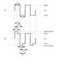
도 14 및 도 15를 참조하면, 비접촉 터치 구동 모드에서 한 타이밍에 둘 이상의 터치 센서(TS)로 공급되는 구동 신호(Vh)는, 접촉 터치 구동 모드에서 다수의 터치 센서(TS)로 공급되는 구동 신호(Vf)를 레퍼런스 신호 파형(Reference waveform)으로 하여, 이러한 레퍼런스 신호 파형에 비해, 정해진 오버 드라이빙 구간(OP) 동안 오버 드라이빙 전압(Vover)만큼 오버 드라이빙 된 신호일 수 있다. 14 and 15, the drive signal Vh supplied to two or more touch sensors TS at one timing in the non-contact touch drive mode is driven by a plurality of touch sensors TS The signal Vf may be a reference signal and the overdrived signal may be overdrived by the overdriving voltage Vover for a predetermined overdriving period OP as compared with the reference signal waveform.
예를 들어, 도 14에 도시된 바와 같이, 비접촉 터치 구동 모드에서의 구동 신호(Vh)의 1개의 펄스에서 오버 드라이빙 구간(OP)은, 1개의 펄스의 전체 폭(HP)에 대응될 수 있다. For example, as shown in Fig. 14, the overdriving period OP in one pulse of the driving signal Vh in the noncontact touch driving mode may correspond to the total width HP of one pulse .
다른 예를 들어, 도 15에 도시된 바와 같이, 비접촉 터치 구동 모드에서의 구동 신호(Vh)의 1개의 펄스에서 오버 드라이빙 구간(OP)은, 1개의 펄스의 전체 폭(HP) 중 일부에 해당할 수 있다.15, the over-driving period OP in one pulse of the drive signal Vh in the noncontact touch drive mode corresponds to a part of the total width HP of one pulse, for example, can do.
도 16a 내지 도 16d은 본 발명에 따른 접촉 터치 구동 모드(핑거 모드) 및 비접촉 터치 구동 모드 각각에서의 구동신호(Vf, Vh)의 더욱 구체적인 4가지 예시들이다. 16A to 16D are four more specific examples of the driving signals Vf and Vh in the contact touch driving mode (finger mode) and the non-contact touch driving mode according to the present invention, respectively.
도 16a의 일 예와 같이, 터치 센싱 회로(100)에서 생성되어 출력되어 구동 신호는, 터치 구동 모드(접촉 터치 구동 모드, 비접촉 터치 구동 모드)에 따라 달라질 수 있다. As shown in FIG. 16A, the driving signal generated and outputted by the
도 16a을 참조하면, 접촉 터치 구동인 경우 다수의 터치센서(TS)로 공급되는 구동 신호(Vf)는, 기준 전압(Vo)을 갖는 로우 레벨 구간(LP)과, 기준 전압(Vo)보다 높은 구동전압(Vd)을 갖는 하이 레벨 구간(HP)이 반복되는 변조 펄스(Modulation Pulse)이다. 16A, the driving signal Vf supplied to the plurality of touch sensors TS in the case of touch-touch driving is divided into a low-level section LP having the reference voltage Vo and a low- Is a modulation pulse in which a high level section HP having a driving voltage Vd is repeated.
도 16a을 참조하면, 비접촉 터치 구동인 경우 다수의 터치센서(TS)로 공급되는 구동 신호(Vh)는, 기준 전압(Vo)을 갖는 로우 레벨 구간(LP)과, 기준 전압(Vo)보다 높은 전압(Vd+Vover, Vd)을 갖는 하이 레벨 구간(HP)이 반복되는 변조 펄스(Modulation Pulse)이다. 16A, in the non-contact touch driving, the driving signal Vh supplied to the plurality of touch sensors TS is divided into a low level section LP having a reference voltage Vo and a low level section LP having a higher voltage than the reference voltage Vo Is a modulation pulse in which a high level section HP having a voltage (Vd + Vover, Vd) is repeated.
도 16a을 참조하면, 비접촉 터치 구동인 경우 다수의 터치센서(TS)로 공급되는 구동 신호(Vh)에서, 하이 레벨 구간(HP)은 오버 드라이빙 구간(OP)과 노말 하이 레벨 구간(NHP)으로 이루어질 수 있다. 16A, in the non-contact touch driving, in the driving signal Vh supplied to the plurality of touch sensors TS, the high level section HP is divided into the over driving section OP and the normal high level section NHP Lt; / RTI >
비접촉 터치 구동인 경우 다수의 터치센서(TS)로 공급되는 구동 신호(Vh)에서, 하이 레벨 구간(HP) 내 오버 드라이버 구간(OP)에서는 구동전압(Vd)보다 오버 드라이빙 전압(Vover)만큼 높은 오버 드라이빙 구동전압(Vd+Vover)을 갖는다. In the non-contact touch driving, the driving signal Vh supplied to the plurality of touch sensors TS is higher than the driving voltage Vd by the overdrive voltage Vover in the over-driver section OP within the high- Driving voltage (Vd + Vover).
비접촉 터치 구동인 경우 다수의 터치센서(TS)로 공급되는 구동 신호(Vh)에서, 하이 레벨 구간(HP) 내 노말 하이 레벨 구간(NHP)에서는 기준전압(Vo)보다 높은 구동전압(Vd)을 갖는다. The drive voltage Vd that is higher than the reference voltage Vo in the normal high level section NHP in the high level section HP is set to be higher than the reference voltage Vo in the drive signal Vh supplied to the plurality of touch sensors TS in the non- .
도 16b의 다른 예와 같이, 터치 센싱 회로(100)에서 생성되어 출력되어 구동 신호는, 터치 구동 모드(접촉 터치 구동 모드, 비접촉 터치 구동 모드)에 따라 달라질 수 있다. As shown in another example of FIG. 16B, the driving signal generated and output by the
도 16b를 참조하면, 접촉 터치 구동인 경우 다수의 터치센서(TS)로 공급되는 구동 신호(Vf)는, 기준 전압(Vo)을 갖는 로우 레벨 구간(LP)과, 기준 전압(Vo)보다 높은 구동전압(Vd)을 갖는 하이 레벨 구간(HP)이 반복되는 변조 펄스(Modulation Pulse)이다.16B, the driving signal Vf supplied to a plurality of touch sensors TS in the case of contact touch driving is divided into a low level section LP having a reference voltage Vo and a low level section LP having a voltage higher than the reference voltage Vo Is a modulation pulse in which a high level section HP having a driving voltage Vd is repeated.
도 16b를 참조하면, 비접촉 터치 구동인 경우 다수의 터치센서(TS)로 공급되는 구동 신호(Vh)는, 기준 전압(Vo)을 갖는 로우 레벨 구간(LP)과 기준 전압(Vo)보다 높은 전압(Vd+Vover, Vd)을 갖는 하이 레벨 구간(HP)이 반복되는 변조 펄스(Modulation Pulse)이다. 16B, in the case of non-contact touch driving, the driving signal Vh supplied to the plurality of touch sensors TS is divided into a low level section LP having a reference voltage Vo and a high voltage And a high level section (HP) having a voltage level (Vd + Vover, Vd) is repeated.
한 프레임 구간 내 터치 구동 구간(비접촉 터치 구동 구간) 중 제1 구동 구간(Tover) 동안, 하이 레벨 구간(HP)은 오버 드라이빙 구간(OP)과 노말 하이 레벨 구간(NHP)으로 이루어질 수 있다. During the first driving period Tover of the touch driving period (non-contact touch driving period) within one frame period, the high level period HP may be an over driving period OP and a normal high level period NHP.
한 프레임 구간 내 터치 구동 구간(비접촉 터치 구동 구간) 중 제2 구동 구간(Tnormal) 동안, 하이 레벨 구간(HP)은 노말 하이 레벨 구간(NHP)만으로 이루어질 수 있다. During the second driving period Tnormal of the touch driving period (non-contact touch driving period) within one frame period, the high level period HP can be made only of the normal high level period NHP.
도 16b를 참조하면, 한 프레임 구간 내 비접촉 터치 구동 구간 동안, 다수의 터치센서(TS)로 공급되는 구동 신호(Vh)에서, 노말 하이 레벨 구간(NHP)에서는 기준전압(Vo)보다 미리 정해진 전압(터치 센싱에 필요한 전압)만큼 높은 구동전압(Vd)을 가질 수 있다. Referring to FIG. 16B, in the non-contact touch driving period within one frame period, in the driving signal Vh supplied to the plurality of touch sensors TS, in the normal high level section NHP, (Voltage required for touch sensing).
한 프레임 구간 내 터치 구동 구간(비접촉 터치 구동 구간) 중 제1 구동 구간(Tover) 동안, 다수의 터치센서(TS)로 공급되는 구동 신호(Vh)에서, 오버 드라이버 구간(OP)에서는 구동전압(Vd)보다 오버 드라이빙 전압(Vover)만큼 높은 오버 드라이빙 구동전압(Vd+Vover)를 가질 수 있다.In the overdrive section OP from the drive signal Vh supplied to the plurality of touch sensors TS during the first drive period Tover of the touch drive period (non-contact touch drive period) within one frame period, (Vd + Vover) higher than the overdriving voltage (Vover) than the overdriving voltage (Vd).
도 16c의 또 다른 예와 같이, 터치 센싱 회로(100)에서 생성되어 출력되어 구동 신호는, 터치 구동 모드(접촉 터치 구동 모드, 비접촉 터치 구동 모드)에 따라 달라질 수 있다. As shown in another example of FIG. 16C, the driving signal generated and output by the
도 16c를 참조하면, 접촉 터치 구동인 경우 다수의 터치센서(TS)로 공급되는 구동 신호(Vf)는, 로우 레벨 구간(LP)과 하이 레벨 구간(HP)이 반복되는 변조 펄스일 수 있다. Referring to FIG. 16C, the drive signal Vf supplied to the plurality of touch sensors TS in the touch-touch driving may be a modulation pulse in which the low level section LP and the high level section HP are repeated.
접촉 터치 구동인 경우 다수의 터치센서(TS)로 공급되는 구동 신호(Vf)에서, 하이 레벨 구간(HP)은 기준전압(Vo)보다 높은 하이 레벨 구동전압(Vpd)을 갖는 노말 하이 레벨 구간(NHP)일 수 있고, 로우 레벨 구간(LP)은 기준전압(Vo)보다 낮은 로우 레벨 구동전압(Vnd)을 갖는 노말 로우 레벨 구간(NLP)일 수 있다. In the case of the contact touch driving, in the driving signal Vf supplied to the plurality of touch sensors TS, the high level section HP is divided into the normal high level section having the high level driving voltage Vpd higher than the reference voltage Vo NHP), and the low level section LP may be a normal low level section NLP having a low level driving voltage Vnd lower than the reference voltage Vo.
도 16c를 참조하면, 비접촉 터치 구동인 경우 다수의 터치센서(TS)로 공급되는 구동 신호(Vh)는, 로우 레벨 구간(LP)과 하이 레벨 구간(HP)이 반복되는 변조 펄스일 수 있다. Referring to FIG. 16C, the driving signal Vh supplied to the plurality of touch sensors TS in the case of non-contact touch driving may be a modulation pulse in which the low level section LP and the high level section HP are repeated.
도 16c를 참조하면, 비접촉 터치 구동인 경우 다수의 터치센서(TS)로 공급되는 구동 신호(Vh)에서, 하이 레벨 구간(HP)은 하이 레벨 오버 드라이빙 구간(HOP)과 노말 하이 레벨 구간(NHP)으로 이루어질 수 있다.16C, in the non-contact touch driving, in the driving signal Vh supplied to the plurality of touch sensors TS, the high level section HP is divided into the high level over driving section HOP and the normal high level section NHP ).
여기서, 비접촉 터치 구동인 경우 다수의 터치센서(TS)로 공급되는 구동 신호(Vh)의 하이 레벨 구간(HP)에서, 하이 레벨 오버 드라이빙 구간(HOP)에서는, 하이 레벨 구동전압(Vpd)보다 오버 드라이빙 전압(Vover)만큼 높은 하이 레벨 오버 드라이빙 구동전압(Vpd+Vover)를 갖는다. Here, in the non-contact touch driving, in the high level section HP of the driving signal Vh supplied to the plurality of touch sensors TS, the high level driving voltage Vpd is higher than the high level driving voltage Vpd in the high level over driving section HOP Level overdriving driving voltage Vpd + Vover which is higher than the driving voltage Vover.
그리고, 비접촉 터치 구동인 경우 다수의 터치센서(TS)로 공급되는 구동 신호(Vh)의 하이 레벨 구간(HP)에서, 노말 하이 레벨 구간(NHP)에서는, 기준전압(Vo)보다 터치 센싱에 필요한 전압만큼 높은 하이 레벨 구동전압(Vpd)을 가질 수 있다. In the non-contact touch driving, in the high level section HP of the driving signal Vh supplied to the plurality of touch sensors TS, in the normal high level section NHP, Level driving voltage Vpd as high as the voltage.
비접촉 터치 구동인 경우 다수의 터치센서(TS)로 공급되는 구동 신호(Vh)에서, 로우 레벨 구간(LP)은 로우 레벨 오버 드라이빙 구간(LOP)과 노말 로우 레벨 구간(NLP)으로 이루어질 수 있다. In the non-contact touch driving, in the driving signal Vh supplied to the plurality of touch sensors TS, the low level section LP may be composed of the low level over driving section LOP and the normal low level section NLP.
여기서, 비접촉 터치 구동인 경우 다수의 터치센서(TS)로 공급되는 구동 신호(Vh)의 로우 레벨 구간(LP)에서, 로우 레벨 오버 드라이빙 구간(LOP)에서는, 로우 레벨 구동전압(Vnd)보다 오버 드라이빙 전압(Vover)만큼 낮은 로우 레벨 오버 드라이빙 구동전압(Vnd-Vover)를 갖는다. Here, in the non-contact touch driving, in the low level section LP of the driving signal Vh supplied to the plurality of touch sensors TS, in the low level over driving section LOP, And a low level over driving driving voltage Vnd-Vover which is lower than the driving voltage Vover.
그리고, 비접촉 터치 구동인 경우 다수의 터치센서(TS)로 공급되는 구동 신호(Vh)의 로우 레벨 구간(LP)에서, 노말 로우 레벨 구간(NLP)에서는 기준전압(Vo)보다 낮은 로우 레벨 구동전압(Vnd)을 가질 수 있다. In the non-contact touch driving, in the low level section LP of the driving signal Vh supplied to the plurality of touch sensors TS, in the normal low level section NLP, the low level driving voltage (Vnd).
도 16d의 또 다른 예와 같이, 터치 센싱 회로(100)에서 생성되어 출력되어 구동 신호는, 터치 구동 모드(접촉 터치 구동 모드, 비접촉 터치 구동 모드)에 따라 달라질 수 있다. As shown in another example of FIG. 16D, the driving signal generated and output by the
도 16d을 참조하면, 접촉 터치 구동인 경우 다수의 터치센서(TS)로 공급되는 구동 신호(Vf)는, 로우 레벨 구간(LP)과 하이 레벨 구간(HP)이 반복되는 변조 펄스일 수 있다. Referring to FIG. 16D, the driving signal Vf supplied to the plurality of touch sensors TS in the case of contact touch driving may be a modulation pulse in which the low level section LP and the high level section HP are repeated.
접촉 터치 구동인 경우 다수의 터치센서(TS)로 공급되는 구동 신호(Vf)에서, 하이 레벨 구간(HP)은 기준전압(Vo)보다 높은 하이 레벨 구동전압(Vpd)을 갖는 노말 하이 레벨 구간(NHP)일 수 있고, 로우 레벨 구간(LP)은 기준전압(Vo)보다 낮은 로우 레벨 구동전압(Vnd)을 갖는 노말 로우 레벨 구간(NLP)일 수 있다.In the case of the contact touch driving, in the driving signal Vf supplied to the plurality of touch sensors TS, the high level section HP is divided into the normal high level section having the high level driving voltage Vpd higher than the reference voltage Vo NHP), and the low level section LP may be a normal low level section NLP having a low level driving voltage Vnd lower than the reference voltage Vo.
도 16d을 참조하면, 비접촉 터치 구동인 경우 다수의 터치센서(TS)로 공급되는 구동 신호(Vh)는, 로우 레벨 구간(LP)과 하이 레벨 구간(HP)이 반복되는 변조 펄스일 수 있다. Referring to FIG. 16D, the driving signal Vh supplied to the plurality of touch sensors TS in the non-contact touch driving may be a modulation pulse in which the low level section LP and the high level section HP are repeated.
도 16d을 참조하면, 비접촉 터치 구동 구간 중 제1 구동 구간(Tover) 동안, 하이 레벨 구간(HP)은 하이 레벨 오버 드라이빙 구간(HOP)과 노말 하이 레벨 구간(NHP)으로 이루어지고, 로우 레벨 구간(LP)은 로우 레벨 오버 드라이빙 구간(LOP)과 노말 로우 레벨 구간(NLP)으로 이루어질 수 있다.Referring to FIG. 16D, during the first driving period Tover of the non-contact touch driving period, the high level section HP is composed of a high level over driving section HOP and a normal high level section NHP, (LP) may consist of a low level overdriving section (LOP) and a normal low level section (NLP).
도 16d을 참조하면, 비접촉 터치 구동 구간 중 제2 구동 구간(Tnormal) 동안, 하이 레벨 구간(HP)은 노말 하이 레벨 구간(NHP)만으로 이루어지고, 로우 레벨 구간(LP)은 노말 로우 레벨 구간(NLP)만으로 이루어질 수 있다.Referring to FIG. 16D, during the second driving period Tnormal of the non-contact touch driving period, the high level section HP consists of the normal high level section NHP, and the low level section LP includes the normal low level section NLP).
하이 레벨 오버 드라이빙 구간(HOP)에서는 하이 레벨 구동전압(Vpd)보다 오버 드라이빙 전압(Vover)만큼 높은 하이 레벨 오버 드라이빙 구동전압(Vpd+Vover)를 갖고, 노말 하이 레벨 구간(NHP)에서는 기준전압(Vo)보다 높은 하이 레벨 구동전압(Vpd)을 가질 수 있다. In the high level over driving section HOP, a high level over driving driving voltage Vpd + Vover which is higher than the high level driving voltage Vpd by the over driving voltage Vover is provided. In the normal high level section NHP, Level driving voltage Vpd higher than the high-level driving voltage Vpd.
로우 레벨 오버 드라이빙 구간(LOP)에서는 로우 레벨 구동전압(Vnd)보다 오버 드라이빙 전압(Vover)만큼 낮은 로우 레벨 오버 드라이빙 구동전압(Vnd-Vover)를 갖고, 노말 로우 레벨 구간(NLP)에서는 기준전압(Vo)보다 낮은 로우 레벨 구동전압(Vnd)을 가질 수 있다. Level drive voltage Vnd-Vover which is lower than the low-level drive voltage Vnd by the overdrive voltage Vover in the low-level overdriving period LOP and the low-level overdriving drive voltage Vnd- Vo) lower than the threshold voltage Vth.
이상에서 전술한 바와 같이, 다수의 터치센서(TS)는, 디스플레이 구동 구간 동안 디스플레이 구동전압(예: 화소전압과 대응되어 전계를 형성하는 공통전압)이 공급되고, 접촉 터치 구동 구간 동안 접촉 터치 구동신호(Vf)가 공급되며, 비접촉 터치 구동 구간 동안 비접촉 터치 구동신호(Vh)가 공급될 수 있다. As described above, the plurality of touch sensors TS are supplied with the display driving voltage (e.g., a common voltage corresponding to the pixel voltage to form an electric field) during the display driving period, And the non-contact touch driving signal Vh can be supplied during the non-contact touch driving period.
도 17은 본 발명에 따른 표시장치의 구동 시, 한 프레임 구간이 디스플레이 구동 구간(D), 접촉 터치 구동 구간(TF) 및 비접촉 터치 구동 구간(TH)으로 시분할 방식으로 진행되는 경우 구동 타이밍도이다. 17 is a driving timing diagram when one frame section is driven in a time division manner in a display driving section D, a contact touch driving section TF, and a non-contact touch driving section TH when the display device according to the present invention is driven .
도 17을 참조하면, 한 프레임(1 Frame) 구간은, 디스플레이 구동 구간(D), 접촉 터치 구동 구간(TF) 및 비접촉 터치 구동 구간(TH)으로 시분할될 수 있다. Referring to FIG. 17, one frame period may be divided into a display driving period D, a contact touch driving period TF, and a non-contact touch driving period TH.
한 프레임(1 Frame) 구간이 시분할된 디스플레이 구동 구간(D), 접촉 터치 구동 구간(TF) 및 비접촉 터치 구동 구간(TH) 각각은 동일한 시간 길이를 가질 수도 있고(Ld=Lf=Lh), 적어도 한 구간은 다른 시간 길이를 가질 수도 있다(Ld, Lf, Lh 중 적어도 하나는 다른 값). Each of the display driving section D, the touch operation driving section TF and the noncontact touch operation section TH may have the same time length (Ld = Lf = Lh) for one frame (one frame) One interval may have a different length of time (at least one of Ld, Lf, and Lh is different).
도 18은 본 발명에 따른 표시장치의 구동 시, 한 프레임 구간이 디스플레이 구동 구간(D), 접촉 터치 구동 구간(TF) 및 비접촉 터치 구동 구간(TH)으로 시분할 방식으로 진행되는 경우, 접촉 터치 구동 구간(TF) 및 비접촉 터치 구동 구간(TH)의 길이 가변 특성을 나타낸 도면이다. 18 is a timing chart illustrating a case where one frame period is driven in a time division manner by a display driving period D, a contact touch driving period TF, and a noncontact touch driving period TH during the driving of the display device according to the present invention, And the length TF and the length of the non-contact touch driving section TH.
도 18을 참조하면, 화상 표시 구동이 되고 있는 동안, 접촉 터치 구동 구간(TF)의 시간 길이(Lf)와 비접촉 터치 구동 구간(TH)의 시간적인 길이(Lh)는 적응적으로 서로 가변될 수 있다. 18, the time length Lf of the contact touch driving period TF and the temporal length Lh of the non-contact touch driving period TH may be adaptively mutually changed have.
예를 들어, 접촉 터치가 많이 발생하는 상황인 경우, 접촉 터치 구동 구간(TF)의 시간적인 길이(Lf)를 길게, 비접촉 터치 구동 구간(TH)의 시간적인 길이(Lh)를 짧게 제어할 수 있다. For example, in a situation where a large number of touch taps occur, the time length Lf of the contact touch driving period TF can be long and the time length Lh of the noncontact touch driving period TH can be controlled to be short have.
다른 예를 들어, 비접촉 터치가 많이 발생하는 상황인 경우, 접촉 터치 구동 구간(TF)의 시간적인 길이(Lf)를 짧게, 비접촉 터치 구동 구간(TH)의 시간적인 길이(Lh)를 길게 제어할 수 있다. For example, in a situation where a large number of noncontact touches occur, the temporal length Lf of the contact touch driving period TF may be shortened and the temporal length Lh of the noncontact touch driving period TH may be controlled to be long .
도 19는 본 발명에 따른 표시장치의 구동 시, 한 프레임 구간이 디스플레이 구동 구간(D) 및 터치 구동 구간으로 시분할되고, 터치 구동 구간이 접촉 터치 구동 구간(TF) 및 비접촉 터치 구동 구간(TH) 중 하나로 진행되는 경우에 대한 구동 타이밍도이다. FIG. 19 is a timing chart illustrating a method of driving a display device according to an embodiment of the present invention. Referring to FIG. 19, when one frame period is divided into a display driving period D and a touch driving period, Fig. 2 is a driving timing chart for the case of driving to one of the two modes.
도 19를 참조하면, 한 프레임 구간은, 디스플레이 구동 구간(D) 및 접촉 터치 구동 구간(TF)으로 시분할되거나, 디스플레이 구동 구간(D) 및 비접촉 터치 구동 구간(TH)으로 시분할될 수 있다.Referring to FIG. 19, one frame period may be time-divided into a display driving period D and a contact touch driving period TF, or may be time-divided into a display driving period D and a non-contact touch driving period TH.
제1 프레임(Frame #1) 구간 내 접촉 터치 구동 구간(TF) 이후, 접촉 터치가 존재하는 것으로 판단되면, 제1 프레임(Frame #1) 구간의 다음 번째의 제2 프레임(Frame #2) 구간은, 디스플레이 구동 구간(D) 및 접촉 터치 구동 구간(TF)으로 시분할될 수 있다. If it is determined that there is a contact touch after the touch-touch driving period TF in the first frame (Frame # 1), the second frame (Frame # 2) of the next frame of the first frame May be time-divided by the display driving period D and the contact touch driving period TF.
접촉 터치가 미존재하는 것으로 판단되면, 제1 프레임(Frame #1) 구간의 의 다음 번째의 제2 프레임(Frame #2) 구간은, 디스플레이 구동 구간(D) 및 비접촉 터치 구동 구간(TH)으로 시분할될 수 있다. If it is determined that there is no contact touch, the second frame (Frame # 2) next to the first frame (Frame # 1) is transmitted to the display driving section D and the non-contact touch driving section TH It can be time-divided.
도 20은 본 발명에 따른 표시장치의 터치 구동 시 발생하는 기생 캐패시터(Cp1, Cp2)와 이에 따른 터치 센싱 에러를 개선하기 위하여, 불필요한 기생 캐패시턴스(Cp1, Cp2)를 제거하여 터치 센싱 정확도를 향상시킬 수 있는 구동 방식인 로드 프리 구동(LFD: Load Free Driving) 방식을 설명하기 위한 도면이다. 20 is a diagram for explaining a method for improving touch sensing accuracy by removing unnecessary parasitic capacitances Cp1 and Cp2 in order to improve the parasitic capacitors Cp1 and Cp2 generated during the touch operation of the display device according to the present invention and the touch sensing errors, (LFD) method, which is a driving method capable of driving a vehicle.
위에서 언급한 로드 프리 구동(LFD: Load Free Driving)는, 터치 센싱 정확도를 떨어뜨리는 로드(Load)를 제거하는 구동으로 정의될 수 있다. 이러한 로드 프리 구동은 터치 센싱을 위해 다수의 터치센서(TS)로 구동신호를 순차적으로 인가하는 메인 터치 구동과 함께 진행될 수 있다.The above-mentioned load free driving (LFD) can be defined as a driving that removes a load that lowers the touch sensing accuracy. Such load-free driving can be performed together with main touch driving in which driving signals are sequentially applied to a plurality of touch sensors TS for touch sensing.
여기서, 터치 센싱 정확도를 떨어뜨리는 로드(Load)는, 다수의 터치센서(TS)로 구동신호를 순차적으로 인가하여 터치 구동을 하는 동안, 터치 센싱을 위하여 반드시 형성되어야 하는 포인터와 터치센서(TS) 사이의 캐패시턴스 이외에, 표시패널(110) 내 다른 패턴들(예: 데이터 라인, 게이트 라인 등)과 다수의 터치센서(TS) 사이에 불필요하게 형성되는 기생 캐패시턴스에 의해 발생한다. 이러한 기생 캐패시턴스는 캐패시턴스 변화량을 토대로 터치 센싱을 하는 방식에서는 캐패시턴스 변화량을 변하게 하여 센싱 정확도를 떨어뜨릴 수 있다.The load that lowers the accuracy of the touch sensing may include a pointer and a touch sensor TS that must be formed for touch sensing during the touch driving by sequentially applying a driving signal to a plurality of touch sensors TS, And parasitic capacitance unnecessarily formed between the other patterns (e.g., data lines, gate lines, and the like) in the display panel 110 and the plurality of touch sensors TS. Such a parasitic capacitance can reduce the sensing accuracy by changing the amount of capacitance change in a method of performing touch sensing based on the amount of change in capacitance.
도 20을 참조하면, 터치 구동 시, 터치센서(TS)에 구동신호(Vf, Vh)를 공급하는 동안, 터치센서(TS)와 데이터 라인(DL) 사이에 기생 캐피시터(Cp1)가 형성될 수 있고, 터치센서(TS)와 게이트 라인(GL) 사이에 기생 캐피시터(Cp2)가 형성될 수 있다. 20, a parasitic capacitor Cp1 may be formed between the touch sensor TS and the data line DL during supply of the driving signals Vf and Vh to the touch sensor TS during the touch driving operation And a parasitic capacitor Cp2 may be formed between the touch sensor TS and the gate line GL.
이러한 기생 캐패시터(Cp1, Cp2)는, 터치 구동 및 터치 센싱에 있어서 로드(Load)로 작용하여, 터치 센싱 에러를 유발할 수 있다. These parasitic capacitors Cp1 and Cp2 act as a load in touch driving and touch sensing, and can cause a touch sensing error.
이에, 본 발명은 불필요한 기생 캐패시턴스(Cp1, Cp2)를 제거하여 로드를 줄여줄 수 있는 터치 구동 방법을 제공할 수 있다. Accordingly, the present invention can provide a touch driving method capable of reducing unnecessary parasitic capacitances (Cp1, Cp2) to reduce the load.
본 발명에 따른 로드 프리 터치 구동 방법에 따르면, 다수의 터치센서(TS)로 구동신호가 공급되는 동안, 표시패널(10)에 배치된 적어도 하나의 데이터 라인(DL)으로 구동신호(Vf, Vh)와 동위상의 로드 프리 구동신호(LFDdl)가 공급될 수 있다.According to the load-free touch driving method of the present invention, the driving signals (Vf, Vh (Vh), Vs, Vs) are supplied to at least one data line DL disposed on the
본 발명에 따른 로드 프리 터치 구동 방법에 따르면, 다수의 터치센서(TS)로 구동신호가 공급되는 동안, 표시패널(10)에 배치된 적어도 하나의 게이트 라인(GL)으로 구동신호(Vf, Vh)와 동위상의 로드 프리 구동신호(LFDgl)가 공급될 수 있다.According to the load-free touch driving method of the present invention, the driving signals (Vf, Vh (Vh, Vh)) are supplied to at least one gate line GL disposed on the
여기서, 로드 프리 구동신호(LFDdl, LFDgl)는, 비접촉 터치 구동인 경우와 접촉 터치 구동인 경우 각각에 대한 구동신호(Vf, Vh)의 신호 세기 및 신호 모양과 대응되는 신호 세기 및 신호 모양을 가질 수 있다.Here, the rod-free driving signals LFDdl and LFDgl have signal intensities and signal shapes corresponding to the signal intensities and signal shapes of the driving signals Vf and Vh for the contactless touch driving and for the contact touch driving, .
이에 따라, 터치 구동 구간(TF, TH) 동안, 터치센서(TS)와 데이터 라인(DL) 간의 전위차와, 터치센서(TS)와 게이트 라인(GL) 간의 전위차가 최소화되거나 없어져서, 터치센서(TS)와 데이터 라인(DL) 사이의 기생 캐패시턴스(Cp1)과, 터치센서(TS)와 게이트 라인(GL) 사이의 기생 캐패시턴스(Cp2)가 줄어들거나 제거될 수 있다. 이에 따라, 센싱 정확도가 향상될 수 있다.The potential difference between the touch sensor TS and the data line DL and the potential difference between the touch sensor TS and the gate line GL are minimized or eliminated during the touch driving periods TF and TH, The parasitic capacitance Cp1 between the data line DL and the data line DL and the parasitic capacitance Cp2 between the touch sensor TS and the gate line GL can be reduced or eliminated. Thus, the sensing accuracy can be improved.
본 발명에 따른 터치 센싱 회로(100)는, 별도의 터치 집적회로(Touch Integrated Circuit)로 구현될 수 있다. The
경우에 따라서는, 본 발명에 따른 터치 센싱 회로(100)는, 데이터 구동 집적회로 칩 형태로 구현된 데이터 구동 회로(24)의 내부 회로일 수도 있다. In some cases, the
아래에서는, 터치 센싱 회로(100)가 데이터 구동 회로(24)의 내부에 포함된 경우, 도 21 내지 도 23을 참조하여 데이터 구동 회로(24)를 개략적으로 설명한다. In the following, when the
도 21 및 도 22를 참조하면, 데이터 구동회로(24)는, 데이터 구동부(미도시) 이외에, 1개의 터치 센싱 회로(100) 및 1개의 멀티플렉서(MUX)를 포함할 수 있다. 21 and 22, the
도 23을 참조하면, 데이터 구동회로(24)는, 데이터 구동부(미도시) 이외에, 2개 이상의 터치 센싱 회로(100-1, 100-2) 및 2개 이상의 멀티플렉서(MUX)를 포함할 수 있다. 23, the
도 21 내지 도 23을 참조하면, 본 발명에 따른 데이터 구동회로(24)는, 표시패널(10)에 배치된 다수의 데이터 라인과 전기적으로 연결되고, 표시패널(10)에 배치된 다수의 터치센서(TS)와 다수의 센싱라인(SL)을 통해 전기적으로 연결될 수 있다. 21 to 23, the
본 발명에 따른 데이터 구동회로(24)는, 디스플레이 구동 모드 시, 다수의 데이터 라인으로 데이터 전압을 출력하고, 터치 구동 모드 시, 다수의 터치센서(TS)로 구동 신호를 순차적으로 공급할 수 있다. The
본 발명에 따른 데이터 구동회로(24)는, 접촉 터치 구동인 경우, 임의의 한 타이밍에 하나의 터치센서(TS)로 구동 신호(Tf)를 공급하고, 비접촉 터치 구동인 경우, 임의의 한 타이밍에 둘 이상의 터치센서(TS)로 구동 신호(Th)를 공급할 수 있다. The
본 발명에 따른 데이터 구동회로(24)는, 비접촉 터치 구동인 경우, 접촉 터치 구동인 경우에 비해, 큰 신호 세기를 갖는 구동 신호를 공급할 수 있다.In the non-contact touch driving, the
본 발명에 따른 데이터 구동회로(24)는, 터치 구동 모드 시, 다수의 터치센서(TS) 중 하나 이상의 터치센서로 구동신호가 인가될 수 있도록, 다수의 센싱라인(SL) 중 하나 이상의 센싱라인을 터치 센싱 회로(100)와 전기적으로 연결해주는 스위칭 동작을 하는 하나 이상의 멀티플렉서(MUX)를 포함할 수 있다.The
본 발명에 따른 데이터 구동회로(24)는, 디스플레이 구동 모드 시, 다수의 터치센서(TS)로 공통전압을 공급하고, 터치 구동 모드 시, 다수의 터치센서(TS)로 구동 신호를 순차적으로 공급하도록 스위칭 해주는 하나 이상의 다른 종류의 멀티플렉서를 더 포함할 수 있다. The
본 발명에 따른 데이터 구동회로(24)는, 다수의 터치센서(TS)로 구동신호(Vf 또는 Vh)가 순차적으로 공급되는 동안, 표시패널(10)에 배치된 적어도 하나의 데이터 라인(DL)으로 구동신호(Vf 또는 Vh)와 동위상의 로드 프리 구동신호(LFDdl)를 공급할 수 있다. The
본 발명에 따른 데이터 구동회로(24)는, 표시패널(10)에 배치된 다수의 데이터 라인(DL)과 전기적으로 연결되고, 다수의 센싱 라인을 통해 표시패널(10)에 배치된 다수의 터치센서(TS)와 전기적으로 연결되며, 디스플레이 구동 모드 시, 다수의 데이터 라인(DL)으로 데이터 전압을 출력하고, 터치 구동 모드 시, 다수의 터치센서(TS)로 구동 신호(Vh)를 순차적으로 공급하되, 임의의 한 타이밍에 둘 이상의 터치센서(TS)로 오버 드라이빙 구간(OP)을 갖는 구동 신호(Vh)를 공급할 수 있다. The
여기서, 오버 드라이빙 구간(OP)을 갖는 구동 신호(Vh)가 공급되는 둘 이상의 터치센서(TS)는 인접하게 배치된 터치센서들일 수 있다. Here, the two or more touch sensors TS to which the drive signal Vh having the over-driving period OP is supplied may be adjacent touch sensors.
오버 드라이빙 구간(OP)을 갖는 구동 신호(Vh)가 공급되는 둘 이상의 터치센서(TS)는 센싱 라인 방향으로 인접하게 배치된 터치센서들일 수 있다.The two or more touch sensors TS to which the drive signal Vh having the over-driving section OP is supplied may be touch sensors disposed adjacent to each other in the sensing line direction.
오버 드라이빙 구간(OP)을 갖는 구동 신호(Vh)가 공급되는 둘 이상의 터치센서(TS)는 센싱 라인 방향과 다른 방향으로 인접하게 배치된 터치센서들일 수 있다.Two or more touch sensors TS to which a drive signal Vh having an over-driving section OP is supplied may be touch sensors arranged adjacent to each other in a direction different from the sensing line direction.
본 발명에 따른 데이터 구동회로(24)는, 표시패널(10)에 배치된 다수의 데이터 라인(DL)과 전기적으로 연결되고, 표시패널(10)에 배치된 다수의 터치센서(TS)와 전기적으로 연결되며, 디스플레이 구동 모드 시, 다수의 데이터 라인(DL)으로 데이터 전압을 출력하고, 터치 구동 시, 다수의 터치센서(TS)로 구동 신호를 순차적으로 공급하여 터치 유무를 검출할 수 있다. The
본 발명에 따른 데이터 구동회로(24)는, 접촉 터치 구동인 경우, 도 21에 도시된 바와 같이, 하나의 터치센서(TS)에 해당하는 센싱 영역 단위로 터치 유무를 검출할 수 있다. The
본 발명에 따른 데이터 구동회로(24)는, 비접촉 터치 구동인 경우, 도 22 및 도 23에 도시된 바와 같이, 둘 이상의 터치센서(TS)에 해당하는 블록 형태의 센싱 단위로 터치 유무를 검출할 수 있다. In the case of the non-contact touch driving, the
본 발명에 따른 데이터 구동회로(24)는, 비접촉 터치 구동인 경우, 접촉 터치 구동인 경우에 비해, 큰 신호 세기를 갖는 구동 신호를 공급할 수 있다.In the non-contact touch driving, the
도 24는 본 발명에 따른 터치 센싱 장치에서 다수의 멀티플렉서(MUX 1, MUX 2, … , MUX 5)에 대한 구동 타이밍을 나타낸 도면이다.24 is a diagram showing driving timings for a plurality of multiplexers (
도 24는 본 발명에 따른 터치 센싱 장치에 5개의 멀티플렉서(MUX 1, MUX 2, … , MUX 5)가 포함된 경우에 대하여, 5개의 멀티플렉서(MUX 1, MUX 2, … , MUX 5)가 1개의 프레임 구간이 시분할된 디스플레이 구동 구간(D), 접촉 터치 구동 구간(TF) 및 비접촉 터치 구동 구간(TH) 각각에서 어떻게 사용되는지를 나타낸 도면이다. (
도 24를 참조하면, 디스플레이 구동 구간(D) 동안, 5개의 멀티플렉서(MUX 1, MUX 2, … , MUX 5)는 다수의 터치센서(TS) 모두로 공통전압(Vcom)이 인가되도록 스위칭 동작을 수행한다. 24, during the display driving period D, the five
도 24를 참조하면, 접촉 터치 구동 구간(TF) 동안, 5개의 멀티플렉서(MUX 1, MUX 2, … , MUX 5)는 순차적으로 동작하게 되고, 동작하는 멀티플렉서는 자신과 대응되는 다수의 터치전극(TS)으로 구동신호가 순차적으로 인가될 수 있도록 스위칭 동작을 수행한다. Referring to FIG. 24, five multiplexers (
도 24를 참조하면, 비접촉 터치 구동 구간(TH) 동안, 5개의 멀티플렉서(MUX 1, MUX 2, … , MUX 5) 중 하나 또는 둘 이상이 구동될 수 있다. Referring to FIG. 24, one or more of five multiplexers (
도 25는 본 발명에 따른 터치 센싱 장치에서, 멀티플렉서(MUX i, i=1, 2, … , 5)의 동작을 설명하기 위한 도면이다.25 is a diagram for explaining the operation of the multiplexer (MUX i, i = 1, 2, ..., 5) in the touch sensing apparatus according to the present invention.
도 25를 참조하면, 5개의 멀티플렉서(MUX 1, MUX 2, … , MUX 5) 중 각 멀티플렉서(MUX i, i=1, 2, … , 5)는, 디스플레이 구동 구간(D), 접촉 터치 구동 구간(TF) 및 비접촉 터치 구동 구간(TH) 각각에 맞는 동작을 수행한다. 25, each of the multiplexers MUX i, i = 1, 2, ..., 5 of the five
단, 각 멀티플렉서(MUX i, i=1, 2, … , 5)는 5개의 채널(CH1, CH2, … , CH5)를 갖는다. 즉 각 멀티플렉서(MUX i, i=1, 2, … , 5)는 5개의 센싱 라인(SL)을 통해 5개의 터치센서(TS)와 전기적으로 연결될 수 있다. However, each multiplexer (MUX i, i = 1, 2, ..., 5) has five channels CH1, CH2, ..., CH5. That is, each of the multiplexers MUX i, i = 1, 2, ..., 5 may be electrically connected to five touch sensors TS through five sensing lines SL.
도 25를 참조하면, 디스플레이 구동 구간(D)에서, 각 멀티플렉서(MUX i, i=1, 2, … , 5)는, 5개의 채널(CH1~CH5)을 단락시키고, 서브 멀티플렉서(2530)를 통해 공통전압 인가부(2520)에서 출력된 공통전압(Vcom)을 5개의 센싱 라인(SL)을 통해 5개의 터치센서(TS) 모두로 공급한다. 25, each of the multiplexers MUXi, i = 1, 2, ..., 5 shorts five channels CH1 to CH5, and the
도 25를 참조하면, 접촉 터치 구동 구간(TF)에서, 동작 순서에 따라 동작하는 해당 멀티플렉서(MUX i, i=1, 2, … , 5)에서 5개 채널(CH1~CH5)은 시분할되어 구동신호의 경로가 된다. 25, five channels (CH1 to CH5) in the corresponding multiplexer (MUX i, i = 1, 2, ..., 5) operating in accordance with the operation sequence are time-divisionally driven Signal path.
도 25를 참조하면, 접촉 터치 구동 구간(TF)에서, 동작 순서에 따라 동작하는 해당 멀티플렉서(MUX i, i=1, 2, … , 5)는, 5개의 채널(CH1~CH5) 중 1개의 채널을 선택하여 아날로그 프런트 엔드(2500)와 연결(단락)시킨다. 여기서, 아날로그 프런트 엔드(2500)는 터치 센싱 회로(100) 또는 데이터 구동회로(24)의 내부에 포함될 수도 있고 외부에 포함될 수도 있다. 25, the corresponding multiplexer MUXi (i = 1, 2, ..., 5) operating according to the operation sequence in the contact touch driving period TF is connected to one of the five channels CH1 to CH5 Channel to connect (short-circuit) with the analog
이에 따라, 해당 멀티플렉서(MUX i, i=1, 2, … , 5)는, 5개의 채널(CH1~CH5)는 아날로그 프런트 엔드(2500)에서 출력된 구동신호를 선택된 1개의 채널을 통해 해당 터치센서(TS)로 공급한다. Accordingly, the five channels (CH1 to CH5) of the corresponding multiplexer (MUX i, i = 1, 2, ..., 5) receive the drive signal output from the analog
이때, 해당 멀티플렉서(MUX i, i=1, 2, … , 5)는, 로드 프리 구동부(2510)에서 출력된 로드 프리 구동 신호(LFD 신호)를 서브 멀티플렉서(2530)를 통해 입력 받아, 입력된 로드 프리 구동 신호(LFD 신호)를 선택된 1개의 채널 이외에 나머지 4개의 채널을 통해 대응되는 4개의 터치센서(TS)로 공급한다. At this time, the multiplexer (MUX i, i = 1, 2, ..., 5) receives the load-free driving signal (LFD signal) output from the load-
도 25를 참조하면, 비접촉 터치 구간(TH)에서, 해당 멀티플렉서(MUX i, i=1, 2, … , 5)는, 5개의 채널(CH1~CH5) 중 2개 이상의 채널을 선택하여 단락 시키고, 단락 된 2개 이상의 채널을 아날로그 프런트 엔드(2500)와 연결시킨다. 25, the corresponding multiplexer MUX i, i = 1, 2, ..., 5 selects and short-circuits two or more channels out of the five channels CH1 to CH5 in the noncontact touch section TH , And connects the two or more shorted channels to the analog
이에 따라, 해당 멀티플렉서(MUX i, i=1, 2, … , 5)는, 아날로그 디지털 프런트 엔드(2500)에서 출력된 구동신호를 선택된 2개의 이상의 채널을 통해 2개의 이상의 터치센서(TS)로 구동신호를 공급한다. Accordingly, the multiplexer MUXi (i = 1, 2, ..., 5) outputs the drive signal output from the analog digital
상기의 상세한 설명은 모든 면에서 제한적으로 해석되어서는 아니되고 예시적인 것으로 고려되어야 한다. 본 발명의 범위는 첨부된 청구항의 합리적 해석에 의해 결정되어야 하고, 본 발명의 등가적 범위 내에서의 모든 변경은 본 발명의 범위에 포함된다.The foregoing detailed description should not be construed in all aspects as limiting and should be considered illustrative. The scope of the present invention should be determined by rational interpretation of the appended claims, and all changes within the scope of equivalents of the present invention are included in the scope of the present invention.
100: 터치 센싱회로
102: 선택회로
104: 센싱신호 검출부
111 내지 116: 센싱 영역
121 내지 126: 센싱 라인
131, 132: 출력라인
170, 180, 190: 센싱 블록 영역
200: 호버 활성화 블록100: Touch sensing circuit
102: selection circuit
104: sensing signal detector
111 to 116: sensing area
121 to 126: sensing line
131, 132: output line
170, 180, 190: sensing block area
200: Hover activation block
Claims (39)
상기 다수의 터치 센서로 터치 인지를 위한 구동신호를 공급하고, 상기 다수의 터치 센서를 통해 센싱신호를 검출하는 센싱신호 검출부; 및
터치 구동 시, 상기 다수의 터치 센서를 상기 센싱신호 검출부에 전기적으로 연결해주는 선택회로를 포함하되,
상기 선택회로는,
상기 터치 구동이 접촉 터치 구동인 경우와 상기 터치 구동이 비접촉 터치 구동인 경우에 대하여 상이한 개수의 터치 센서를 상기 센싱신호 검출부에 전기적으로 연결해주되,
상기 접촉 터치 구동인 경우, 상기 다수의 터치 센서를 순차적으로 상기 센싱신호 검출부에 전기적으로 연결해주고,
상기 비접촉 터치 구동인 경우, 상기 다수의 터치 센서 중 둘 이상의 터치 센서를 상기 센싱신호 검출부에 동시에 전기적으로 연결해주는 터치 센싱 장치. A display panel including a plurality of touch sensors;
A sensing signal detector for supplying a driving signal for sensing touch with the plurality of touch sensors and detecting a sensing signal through the plurality of touch sensors; And
And a selection circuit for electrically connecting the plurality of touch sensors to the sensing signal detection unit when the touch is driven,
Wherein the selection circuit comprises:
A touch sensor for electrically connecting a different number of touch sensors to the sensing signal detecting unit in the case where the touch driving is the contact touch driving and the case in which the touch driving is the non-contact touch driving,
Wherein the plurality of touch sensors are electrically connected to the sensing signal detection unit sequentially,
Wherein the touch sensing device electrically connects the at least two touch sensors among the plurality of touch sensors to the sensing signal detector at the same time.
상기 비접촉 터치 구동 시 터치 센서로 공급되는 상기 구동 신호는,
상기 접촉 터치 구동 시 터치 센서로 공급되는 상기 구동 신호를 레퍼런스 신호 파형(Reference waveform)으로 하여, 상기 레퍼런스 신호 파형에 비해, 정해진 오버 드라이빙 구간 동안 오버 드라이빙 전압만큼 오버 드라이빙 된 터치 센싱 장치.The method according to claim 1,
Wherein the driving signal supplied to the touch sensor at the time of non-
Wherein the driving signal supplied to the touch sensor during the touch-touch driving is a reference waveform, and is over-driven by an over-driving voltage during a predetermined over-driving interval as compared with the reference signal waveform.
상기 비접촉 터치 구동 시 터치 센서로 공급되는 상기 구동 신호의 1개의 펄스에서 상기 오버 드라이빙 구간은,
상기 1개의 펄스의 전체 폭에 대응되거나 상기 전체 폭 중 일부에 해당하는 터치 센싱 장치.3. The method of claim 2,
Wherein the overdriving section of one pulse of the driving signal supplied to the touch sensor at the time of non-
And corresponds to the entire width of the one pulse or a part of the entire width.
상기 비접촉 터치 구동인 경우 터치 센서로 공급되는 상기 구동 신호는,
기준 전압을 갖는 로우 레벨 구간과, 상기 기준 전압보다 높은 전압을 갖는 하이 레벨 구간이 반복되되,
상기 하이 레벨 구간은 상기 오버 드라이빙 구간과 노말 하이 레벨 구간으로 이루어지고,
상기 노말 하이 레벨 구간에서는 상기 기준전압보다 높은 구동전압을 갖고,
상기 오버 드라이빙 구간에서는 상기 구동전압보다 오버 드라이빙 전압만큼 높은 오버 드라이빙 구동전압을 갖는 터치 센싱 장치.The method of claim 3,
In the case of the non-contact touch driving, the driving signal supplied to the touch sensor,
A low level section having a reference voltage and a high level section having a voltage higher than the reference voltage are repeated,
Wherein the high level section comprises the overdriving section and the normal high level section,
Level period, and has a driving voltage higher than the reference voltage in the normal high-
And an overdriving driving voltage that is higher than the driving voltage by an overdriving voltage in the overdriving period.
상기 비접촉 터치 구동인 경우 터치 센서로 공급되는 상기 구동 신호는,
기준 전압을 갖는 로우 레벨 구간과 상기 기준 전압보다 높은 전압을 갖는 하이 레벨 구간이 반복되되,
터치 구동 구간 중 제1 구동 구간 동안, 상기 하이 레벨 구간은 상기 오버 드라이빙 구간과 노말 하이 레벨 구간으로 이루어지고,
상기 터치 구동 구간 중 제2 구동 구간 동안, 상기 하이 레벨 구간은 상기 노말 하이 레벨 구간으로 이루어지며,
상기 노말 하이 레벨 구간에서는 상기 기준전압보다 높은 구동전압을 갖고,
상기 오버 드라이빙 구간에서는 상기 구동전압보다 오버 드라이빙 전압만큼 높은 오버 드라이빙 구동전압를 갖는 터치 센싱 장치.The method of claim 3,
In the case of the non-contact touch driving, the driving signal supplied to the touch sensor,
A low level section having a reference voltage and a high level section having a voltage higher than the reference voltage are repeated,
During the first driving period of the touch driving period, the high level period comprises the over driving period and the normal high level period,
During the second driving period of the touch driving period, the high level period comprises the normal high level period,
Level period, and has a driving voltage higher than the reference voltage in the normal high-
And an overdriving driving voltage that is higher than the driving voltage by an overdriving voltage in the overdriving period.
상기 비접촉 터치 구동인 경우 터치 센서로 공급되는 상기 구동 신호는,
로우 레벨 구간과 하이 레벨 구간이 반복되되,
상기 하이 레벨 구간은 하이 레벨 오버 드라이빙 구간과 노말 하이 레벨 구간으로 이루어지고, 상기 로우 레벨 구간은 로우 레벨 오버 드라이빙 구간과 노말 로우 레벨 구간으로 이루어지며,
상기 노말 하이 레벨 구간에서는 기준전압보다 높은 하이 레벨 구동전압을 갖고, 상기 하이 레벨 오버 드라이빙 구간에서는 상기 하이 레벨 구동전압보다 오버 드라이빙 전압만큼 높은 하이 레벨 오버 드라이빙 구동전압을 가지며,
상기 노말 로우 레벨 구간에서는 기준전압보다 낮은 로우 레벨 구동전압을 갖고, 상기 로우 레벨 오버 드라이빙 구간에서는 상기 로우 레벨 구동전압보다 오버 드라이빙 전압만큼 낮은 로우 레벨 오버 드라이빙 구동전압를 갖는 터치 센싱 장치. The method of claim 3,
In the case of the non-contact touch driving, the driving signal supplied to the touch sensor,
The low level section and the high level section are repeated,
Wherein the high level section comprises a high level over driving section and a normal high level section, the low level section comprises a low level over driving section and a normal low level section,
Level driving voltage that is higher than the reference voltage in the normal high level period and has a high level over driving voltage that is higher than the high level driving voltage by the over driving voltage in the high-
And a low level overdriving driving voltage that is lower than the low level driving voltage by an over driving voltage in the low level over driving period.
상기 비접촉 터치 구동인 경우 터치 센서로 공급되는 상기 구동 신호는,
로우 레벨 구간과 하이 레벨 구간이 반복되되,
터치 구동 구간 중 제1 구동 구간 동안, 상기 하이 레벨 구간은 상기 하이 레벨 오버 드라이빙 구간과 노말 하이 레벨 구간으로 이루어지고, 상기 로우 레벨 구간은 상기 로우 레벨 오버 드라이빙 구간과 노말 로우 레벨 구간으로 이루어지고,
상기 터치 구동 구간 중 제2 구동 구간 동안, 상기 하이 레벨 구간은 상기 노말 하이 레벨 구간으로 이루어지고, 상기 로우 레벨 구간은 상기 노말 로우 레벨 구간으로 이루어지며,
상기 노말 하이 레벨 구간에서는 기준전압보다 높은 하이 레벨 구동전압을 갖고, 상기 하이 레벨 오버 드라이빙 구간에서는 상기 하이 레벨 구동전압보다 오버 드라이빙 전압만큼 높은 하이 레벨 오버 드라이빙 구동전압을 가지며,
상기 노말 로우 레벨 구간에서는 기준전압보다 낮은 로우 레벨 구동전압을 갖고, 상기 로우 레벨 오버 드라이빙 구간에서는 상기 로우 레벨 구동전압보다 오버 드라이빙 전압만큼 낮은 로우 레벨 오버 드라이빙 구동전압을 갖는 터치 센싱 장치. The method of claim 3,
In the case of the non-contact touch driving, the driving signal supplied to the touch sensor,
The low level section and the high level section are repeated,
The high level section is composed of the high level overdriving section and the normal high level section during the first driving period of the touch driving section, the low level section comprises the low level over driving section and the normal low level section,
During the second driving period of the touch driving period, the high level period comprises the normal high level period, the low level period comprises the normal low level period,
Level driving voltage that is higher than the reference voltage in the normal high level period and has a high level over driving voltage that is higher than the high level driving voltage by the over driving voltage in the high-
And a low level over driving driving voltage lower than the reference driving voltage in the normal low level period and lower driving driving voltage in the low level over driving period than the low driving voltage.
상기 센싱신호 검출부는 둘 이상의 검출부를 포함하고,
상기 선택회로는 상기 둘 이상의 검출부에 대응되어 연결되는 둘 이상의 멀티플렉서를 포함하는 터치 센싱 장치.The method according to claim 1,
Wherein the sensing signal detection unit includes at least two detection units,
Wherein the selection circuit comprises two or more multiplexers connected in correspondence with the two or more detection units.
상기 둘 이상의 멀티플렉서 각각은 다수의 스위치 그룹을 포함하고,
상기 다수의 스위치 그룹 각각은 상기 다수의 터치 센서와 전기적으로 연결되는 다수의 스위치를 포함하는 터치 센싱 장치.11. The method of claim 10,
Each of the two or more multiplexers including a plurality of switch groups,
Wherein each of the plurality of switch groups includes a plurality of switches electrically connected to the plurality of touch sensors.
상기 다수의 스위치는,
상기 센싱신호 검출부에 연결되는 다수의 출력라인과 상기 다수의 터치 센서에 연결되는 다수의 센싱 라인을 연결해주는 터치 센싱 장치.12. The method of claim 11,
Wherein the plurality of switches comprise:
And a plurality of output lines connected to the sensing signal detector and a plurality of sensing lines connected to the plurality of touch sensors.
상기 다수의 스위치 각각은,
선택신호에 응답하여 해당 출력라인과 해당 센싱 라인을 선택적으로 연결해주는 터치 센싱 장치.13. The method of claim 12,
Each of the plurality of switches includes:
And selectively connects the corresponding output line and a corresponding sensing line in response to the selection signal.
상기 센싱신호 검출부는,
상기 접촉 터치 구동인 경우, 상기 둘 이상의 멀티플렉서에 포함된 모든 스위치가 순차적으로 하나씩 턴-온 됨에 따라, 임의의 한 타이밍에 연결된 하나의 터치 센서로 상기 구동신호를 공급하는 터치 센싱 장치.12. The method of claim 11,
The sensing signal detector may include:
Wherein the touch sensing device supplies the driving signal to one touch sensor connected at an arbitrary timing as all the switches included in the two or more multiplexers are sequentially turned on one by one.
상기 센싱신호 검출부는,
상기 비접촉 터치 구동인 경우, 상기 둘 이상의 멀티플렉서에 포함된 모든 스위치가 둘 이상씩 함께 턴-온 됨에 따라, 임의의 한 타이밍에 함께 연결된 둘 이상의 터치 센서 모두로 상기 구동신호를 공급하는 터치 센싱 장치. 12. The method of claim 11,
The sensing signal detector may include:
The touch sensing device supplies the driving signal to all two or more touch sensors connected together at an arbitrary timing as all switches included in the two or more multiplexers turn on together.
상기 다수의 터치 센서로 상기 구동신호가 공급되는 동안, 상기 표시패널에 배치된 적어도 하나의 데이터 라인으로 상기 구동신호와 동위상의 로드 프리 구동신호가 공급되는 터치 센싱 장치.The method according to claim 1,
And a load-free driving signal of a same level as the driving signal is supplied to at least one data line arranged on the display panel while the driving signal is supplied to the plurality of touch sensors.
상기 다수의 터치 센서로 상기 구동신호가 공급되는 동안, 상기 표시패널에 배치된 적어도 하나의 게이트 라인으로 상기 구동신호와 동위상의 로드 프리 구동신호가 공급되는 터치 센싱 장치.17. The method of claim 16,
And a load-free driving signal of a same level as the driving signal is supplied to at least one gate line disposed on the display panel while the driving signal is supplied to the plurality of touch sensors.
상기 로드 프리 구동신호는,
상기 비접촉 터치 구동인 경우와 상기 접촉 터치 구동인 경우 각각에 대한 상기 구동신호의 신호 세기 및 신호 모양과 대응되는 신호 세기 및 신호 모양을 갖는 터치 센싱 장치. 18. The method of claim 17,
The load-
Wherein the touch sensing device has a signal intensity and a signal shape corresponding to a signal intensity and a signal shape of the drive signal for the non-contact touch drive and the contact touch drive, respectively.
상기 다수의 터치 센서는,
디스플레이 구동 구간 동안 디스플레이 구동전압이 공급되고,
접촉 터치 구동 구간 동안 접촉 터치 구동신호가 공급되며,
비접촉 터치 구동 구간 동안 비접촉 터치 구동신호가 공급되는 터치 센싱 장치. The method according to claim 1,
The plurality of touch sensors include:
A display driving voltage is supplied during a display driving period,
A contact touch driving signal is supplied during the touch touch driving period,
Contact touch driving signal is supplied during a non-contact touch driving period.
한 프레임 구간은 상기 디스플레이 구동 구간, 상기 접촉 터치 구동 구간 및 상기 비접촉 터치 구동 구간으로 시분할되는 터치 센싱 장치. 20. The method of claim 19,
Wherein one frame period is time-divided into the display driving period, the contact touch driving period, and the non-contact touch driving period.
상기 접촉 터치 구동 구간 및 상기 비접촉 터치 구동 구간 각각의 시간적인 길이는 가변되는 터치 센싱 장치. 21. The method of claim 20,
And the temporal length of each of the contact touch driving period and the non-contact touch driving period is variable.
한 프레임 구간은,
상기 디스플레이 구동 구간 및 상기 접촉 터치 구동 구간으로 시분할되거나, 상기 디스플레이 구동 구간 및 상기 비접촉 터치 구동 구간으로 시분할되되,
제1 프레임 구간 내 상기 접촉 터치 구동 구간 이후,
상기 접촉 터치가 존재하는 것으로 판단되면, 제2 프레임 구간은, 상기 디스플레이 구동 구간 및 상기 접촉 터치 구동 구간으로 시분할되고,
상기 접촉 터치가 미존재하는 것으로 판단되면, 상기 제2 프레임 구간은, 상기 디스플레이 구동 구간 및 상기 비접촉 터치 구동 구간으로 시분할되는 터치 센싱 장치.20. The method of claim 19,
In one frame period,
Divided into the display driving period and the contact touch driving period, or divided into the display driving period and the non-contact touch driving period,
After the touch-touch driving period in the first frame period,
If it is determined that the contact touch exists, the second frame period is time-divided into the display driving period and the contact touch driving period,
Wherein the second frame period is time-divided into the display driving period and the non-contact touch driving period when it is determined that the contact touch does not exist.
상기 선택회로는,
상기 접촉 터치 구동인 경우, 한 시점에 1개의 터치 센서를 상기 센싱신호 검출부에 연결해주고,
상기 비접촉 터치 구동인 경우, 한 시점에 2개 이상의 터치 센서를 상기 센싱신호 검출부에 함께 연결해주되,
상기 비접촉 터치 구동인 경우, 상기 센싱신호 검출부에 함께 연결되는 터치 센서 개수를 이벤트 발생에 따라 변경하는 터치 센싱 장치. 8. The method of claim 7,
Wherein the selection circuit comprises:
In the contact touch driving, one touch sensor is connected to the sensing signal detecting unit at one point,
In the non-contact touch driving, at least two touch sensors are connected to the sensing signal detecting unit at one time,
Wherein the number of touch sensors connected to the sensing signal detecting unit is changed in accordance with the occurrence of an event when the contactless touch driving is performed.
터치 구동 시, 다수의 터치 센서를 상기 센싱신호 검출부에 전기적으로 연결해주는 선택회로를 포함하되,
상기 선택회로는,
상기 터치 구동이 접촉 터치 구동인 경우와 상기 터치 구동이 비접촉 터치 구동인 경우에 대하여 상이한 개수의 터치 센서를 상기 센싱신호 검출부에 전기적으로 연결해주되,
상기 접촉 터치 구동인 경우, 상기 다수의 터치 센서를 순차적으로 상기 센싱신호 검출부에 전기적으로 연결해주고,
상기 비접촉 터치 구동인 경우, 상기 다수의 터치 센서 중 둘 이상의 터치 센서를 상기 센싱신호 검출부에 동시에 전기적으로 연결해주는 터치 센싱 회로.A sensing signal detector for sequentially outputting drive signals to be applied to a plurality of touch sensors and detecting a sensing signal through the plurality of touch sensors; And
And a selection circuit for electrically connecting the plurality of touch sensors to the sensing signal detection unit when the touch operation is performed,
Wherein the selection circuit comprises:
A touch sensor for electrically connecting a different number of touch sensors to the sensing signal detecting unit in the case where the touch driving is the contact touch driving and the case in which the touch driving is the non-contact touch driving,
Wherein the plurality of touch sensors are electrically connected to the sensing signal detection unit sequentially,
Wherein the touch sensing circuit electrically connects at least two of the plurality of touch sensors to the sensing signal detection unit.
상기 비접촉 터치 구동인 경우 터치 센서에 인가되는 구동 신호는,
상기 접촉 터치 구동인 경우 터치 센서에 인가되는 구동 신호를 레퍼런스 신호 파형으로 하여, 상기 레퍼런스 신호 파형에 비해, 정해진 오버 드라이빙 구간 동안 오버 드라이빙 전압만큼 오버 드라이빙 된 터치 센싱 회로.25. The method of claim 24,
In the case of the non-contact touch driving,
Wherein the driving signal applied to the touch sensor in the contact touch driving mode is a reference signal waveform and is overdrived by an over driving voltage for a predetermined over driving period as compared with the reference signal waveform.
상기 비접촉 터치 구동 시 터치 센서로 인가되는 상기 구동 신호의 1개의 펄스에서 상기 오버 드라이빙 구간은,
상기 1개의 펄스의 전체 폭에 대응되거나 상기 전체 폭 중 일부에 해당하는 터치 센싱 회로.26. The method of claim 25,
Wherein the over-driving period of one pulse of the driving signal applied to the touch sensor at the time of non-
And corresponds to a total width of the one pulse or to a part of the entire width.
상기 센싱신호 검출부는,
상기 접촉 터치 구동인 경우, 임의의 한 타이밍에, 하나의 터치 센서에 인가될 상기 구동 신호를 출력하고,
상기 비접촉 터치 구동인 경우, 임의의 한 타이밍에, 둘 이상의 터치 센서에 인가될 상기 구동 신호를 출력하는 터치 센싱 회로.25. The method of claim 24,
The sensing signal detector may include:
In the case of the contact touch driving, outputs the driving signal to be applied to one touch sensor at an arbitrary timing,
And outputs the drive signal to be applied to two or more touch sensors at an arbitrary timing in the non-contact touch driving.
터치 구동 모드 시, 상기 다수의 터치 센서로 구동 신호를 순차적으로 공급하되,
접촉 터치 구동인 경우, 임의의 한 타이밍에 하나의 터치 센서로 구동 신호를 공급하고,
비접촉 터치 구동인 경우, 임의의 한 타이밍에 둘 이상의 터치 센서로 구동 신호를 공급하는 터치 센싱 회로.The display panel is electrically connected to a plurality of touch sensors disposed on the display panel,
In the touch driving mode, the driving signals are sequentially supplied to the plurality of touch sensors,
In the case of contact touch driving, a driving signal is supplied to one touch sensor at an arbitrary timing,
A touch sensing circuit for supplying driving signals to two or more touch sensors at an arbitrary timing in the case of non-contact touch driving.
상기 둘 이상의 터치 센서는 서로 인접한 터치 센서인 터치 센싱 회로. 29. The method of claim 28,
Wherein the at least two touch sensors are touch sensors adjacent to each other.
상기 둘 이상의 터치 센서는 센싱 라인 방향으로 인접하거나 센싱 라인 방향과 다른 방향으로 인접한 터치 센서인 터치 센싱 회로. 30. The method of claim 29,
Wherein the at least two touch sensors are adjacent to each other in the sensing line direction or in a direction different from the sensing line direction.
상기 비접촉 터치 구동인 경우 상기 둘 이상의 터치 센서로 공급되는 구동 신호는,
상기 접촉 터치 구동인 경우 상기 하나의 터치 센서로 공급되는 구동 신호를 레퍼런스 신호 파형으로 하여, 상기 레퍼런스 신호 파형에 비해, 정해진 오버 드라이빙 구간 동안 오버 드라이빙 전압만큼 오버 드라이빙 된 터치 센싱 회로.29. The method of claim 28,
Wherein the driving signal supplied to the at least two touch sensors in the non-
Wherein the driving signal supplied to the one touch sensor is a reference signal waveform and is overdrived by an overdriving voltage for a predetermined overdriving period as compared with the reference signal waveform.
터치 구동 시, 상기 다수의 터치 센서로 구동 신호를 순차적으로 공급하여 터치 유무를 검출하되,
접촉 터치 구동인 경우, 하나의 터치 센서에 해당하는 센싱 영역 단위로 터치 유무를 검출하고,
비접촉 터치 구동인 경우, 둘 이상의 터치 센서에 해당하는 블록 단위로 터치 유무를 검출하는 터치 센싱 회로.The display panel is electrically connected to a plurality of touch sensors disposed on the display panel,
Wherein when a touch operation is performed, a driving signal is sequentially supplied to the plurality of touch sensors to detect presence or absence of a touch,
In the case of contact touch driving, the presence or absence of a touch is detected in a sensing area unit corresponding to one touch sensor,
A touch sensing circuit for detecting whether or not touch is performed in units of blocks corresponding to two or more touch sensors in the case of non-contact touch driving.
상기 비접촉 터치 구동인 경우 둘 이상의 터치 센서로 공급되는 구동 신호는,
상기 접촉 터치 구동인 경우 하나의 터치 센서로 공급되는 구동 신호를 레퍼런스 신호 파형으로 하여, 상기 레퍼런스 신호 파형에 비해, 정해진 오버 드라이빙 구간 동안 오버 드라이빙 전압만큼 오버 드라이빙 된 터치 센싱 회로. 33. The method of claim 32,
In the non-contact touch driving, the driving signals supplied to the two or more touch sensors include:
Wherein the driving signal supplied to one touch sensor in the case of the contact touch driving is a reference signal waveform and is overdrived by an over driving voltage for a predetermined over driving period as compared with the reference signal waveform.
상기 표시패널에 배치된 다수의 터치 센서와 전기적으로 연결되며,
디스플레이 구동 모드 시, 상기 다수의 데이터 라인으로 데이터 전압을 출력하고,
터치 구동 모드 시, 상기 다수의 터치 센서로 구동 신호를 순차적으로 공급하되,
접촉 터치 구동인 경우, 임의의 한 타이밍에 하나의 터치 센서로 구동 신호를 공급하고,
비접촉 터치 구동인 경우, 임의의 한 타이밍에 둘 이상의 터치 센서로 구동 신호를 공급하는 데이터 구동회로.A plurality of data lines electrically connected to the plurality of data lines arranged in the display panel,
A plurality of touch sensors disposed on the display panel,
Outputting a data voltage to the plurality of data lines in a display driving mode,
In the touch driving mode, the driving signals are sequentially supplied to the plurality of touch sensors,
In the case of contact touch driving, a driving signal is supplied to one touch sensor at an arbitrary timing,
In a non-contact touch driving, a data driving circuit supplies a driving signal to two or more touch sensors at an arbitrary timing.
상기 구동신호가 공급되는 동안, 상기 표시패널에 배치된 적어도 하나의 데이터 라인으로 상기 구동신호와 동위상의 로드 프리 구동신호를 공급하는 데이터 구동회로.35. The method of claim 34,
And supplies a load-free driving signal at a same level as the driving signal to at least one data line arranged in the display panel while the driving signal is being supplied.
상기 비접촉 터치 구동인 경우 상기 둘 이상의 터치 센서로 공급되는 구동 신호는,
상기 접촉 터치 구동인 경우 상기 하나의 터치 센서로 공급되는 구동 신호를 레퍼런스 신호 파형으로 하여, 상기 레퍼런스 신호 파형에 비해, 정해진 오버 드라이빙 구간 동안 오버 드라이빙 전압만큼 오버 드라이빙 된 데이터 구동회로.35. The method of claim 34,
Wherein the driving signal supplied to the at least two touch sensors in the non-
Wherein the driving signal supplied to the one touch sensor is a reference signal waveform and is overdrived by an overdriving voltage for a predetermined overdriving period as compared with the reference signal waveform.
상기 표시패널에 배치된 다수의 터치 센서와 전기적으로 연결되며,
디스플레이 구동 모드 시, 상기 다수의 데이터 라인으로 데이터 전압을 출력하고,
터치 구동 시, 상기 다수의 터치 센서로 구동 신호를 순차적으로 공급하여 터치 유무를 검출하되,
접촉 터치 구동인 경우, 하나의 터치 센서에 해당하는 센싱 영역 단위로 터치 유무를 검출하고, 비접촉 터치 구동인 경우, 둘 이상의 터치 센서에 해당하는 블록 단위로 터치 유무를 검출하는 데이터 구동회로.A plurality of data lines electrically connected to the plurality of data lines arranged in the display panel,
A plurality of touch sensors disposed on the display panel,
Outputting a data voltage to the plurality of data lines in a display driving mode,
Wherein when a touch operation is performed, a driving signal is sequentially supplied to the plurality of touch sensors to detect presence or absence of a touch,
In the case of contact touch driving, the presence or absence of touch is detected in units of a sensing area corresponding to one touch sensor, and in the case of non-contact touch driving, the presence or absence of touch is detected in units of blocks corresponding to two or more touch sensors.
디스플레이 구동 모드 시, 상기 다수의 데이터 라인으로 데이터 전압을 출력하는 단계; 및
터치 구동 모드 시, 상기 표시패널에 내장된 상기 다수의 터치 센서로 구동 신호를 순차적으로 공급하는 단계를 포함하되,
상기 공급하는 단계는,
접촉 터치 구동인 경우, 임의의 한 타이밍에 하나의 터치 센서로 구동 신호를 공급하고,
비접촉 터치 구동인 경우, 임의의 한 타이밍에 둘 이상의 터치 센서로 구동 신호를 공급하는 표시장치의 구동방법.A method of driving a display device including a display panel in which a plurality of data lines and a plurality of gate lines are arranged, a data driving circuit driving a plurality of data lines, and a gate driving circuit driving a plurality of gate lines,
Outputting a data voltage to the plurality of data lines in a display driving mode; And
And sequentially supplying driving signals to the plurality of touch sensors built in the display panel in a touch driving mode,
Wherein the supplying step comprises:
In the case of contact touch driving, a driving signal is supplied to one touch sensor at an arbitrary timing,
A driving method of a display device that supplies driving signals to at least two touch sensors at an arbitrary timing in the case of noncontact touch driving.
상기 비접촉 터치 구동인 경우 상기 둘 이상의 터치 센서로 공급되는 구동 신호는,
상기 접촉 터치 구동인 경우 상기 하나의 터치 센서로 공급되는 구동 신호를 레퍼런스 신호 파형으로 하여, 상기 레퍼런스 신호 파형에 비해, 정해진 오버 드라이빙 구간 동안 오버 드라이빙 전압만큼 오버 드라이빙 된 표시장치의 구동방법.
39. The method of claim 38,
Wherein the driving signal supplied to the at least two touch sensors in the non-
Wherein the driving signal supplied to the one touch sensor is a reference signal waveform and is overdrived by an overdriving voltage for a predetermined overdriving period as compared with the reference signal waveform.
Priority Applications (4)
| Application Number | Priority Date | Filing Date | Title |
|---|---|---|---|
| EP15191408.2A EP3037931B1 (en) | 2014-12-22 | 2015-10-26 | Touch sensing device and method for driving touch display device |
| US14/927,480 US9507460B2 (en) | 2014-12-22 | 2015-10-30 | Touch sensing device, touch sensing circuit, data driving circuit, and display device driving method |
| CN201510765272.5A CN105718125B (en) | 2014-12-22 | 2015-11-11 | Touch-sensing device, touch-sensing circuit, data drive circuit and display-apparatus driving method |
| TW104142640A TWI590121B (en) | 2014-12-22 | 2015-12-18 | Touch sensing device, touch sensing circuit, data driving circuit, and display device driving method |
Applications Claiming Priority (2)
| Application Number | Priority Date | Filing Date | Title |
|---|---|---|---|
| KR20140185809 | 2014-12-22 | ||
| KR1020140185809 | 2014-12-22 |
Publications (1)
| Publication Number | Publication Date |
|---|---|
| KR101634642B1 true KR101634642B1 (en) | 2016-06-30 |
Family
ID=56352931
Family Applications (1)
| Application Number | Title | Priority Date | Filing Date |
|---|---|---|---|
| KR1020150136677A Active KR101634642B1 (en) | 2014-12-22 | 2015-09-25 | Touch sensing device, touch sensing circuit, data driving circuit, and driving display device driving method |
Country Status (2)
| Country | Link |
|---|---|
| KR (1) | KR101634642B1 (en) |
| TW (1) | TWI590121B (en) |
Cited By (13)
| Publication number | Priority date | Publication date | Assignee | Title |
|---|---|---|---|---|
| KR20180024904A (en) * | 2016-08-31 | 2018-03-08 | 엘지디스플레이 주식회사 | Touch display device and method of driving the same |
| KR20180025351A (en) * | 2016-08-29 | 2018-03-09 | 삼성디스플레이 주식회사 | Touch sensor and display device including the same |
| KR20180079180A (en) * | 2016-12-30 | 2018-07-10 | 엘지디스플레이 주식회사 | Touch control circuit, touch driving circuit and touch display device |
| CN108279799A (en) * | 2016-12-30 | 2018-07-13 | 乐金显示有限公司 | Touch control circuit, touch drive circuit and touch display device |
| KR20190029028A (en) * | 2017-09-11 | 2019-03-20 | 엘지디스플레이 주식회사 | Touch Device And Method Of Driving The Same |
| KR20200080791A (en) * | 2018-12-27 | 2020-07-07 | 엘지디스플레이 주식회사 | Touch display device and touch driving circuit |
| CN112241220A (en) * | 2019-07-18 | 2021-01-19 | 三星电子株式会社 | Touch sensing system and display system including the same |
| KR20210085202A (en) * | 2019-12-30 | 2021-07-08 | 엘지디스플레이 주식회사 | Touch display device and the method of driving the same |
| KR20230092851A (en) * | 2017-12-22 | 2023-06-26 | 엘지디스플레이 주식회사 | Touch panel liquid crystal display device and method for driving the same |
| US11730040B2 (en) | 2020-10-22 | 2023-08-15 | Samsung Display Co., Ltd. | Display device |
| US11816916B2 (en) | 2020-08-18 | 2023-11-14 | Samsung Display Co., Ltd. | Electronic device |
| US12524122B2 (en) | 2023-11-21 | 2026-01-13 | Samsung Display Co., Ltd. | Input sensor, display device and driving method thereof |
| US12568688B2 (en) | 2022-01-21 | 2026-03-03 | Samsung Display Co., Ltd. | Display device and tiled display device |
Families Citing this family (3)
| Publication number | Priority date | Publication date | Assignee | Title |
|---|---|---|---|---|
| WO2018073690A1 (en) * | 2016-10-21 | 2018-04-26 | Semiconductor Energy Laboratory Co., Ltd. | Touch sensor, display device, display module, and electronic device |
| TWI712931B (en) * | 2019-08-13 | 2020-12-11 | 大陸商集創北方(深圳)科技有限公司 | Touch detection method, touch display drive integrated chip and information processing device |
| TWI910634B (en) * | 2024-05-13 | 2026-01-01 | 華碩電腦股份有限公司 | Touch control device and touch control method |
Citations (4)
| Publication number | Priority date | Publication date | Assignee | Title |
|---|---|---|---|---|
| KR20130134007A (en) * | 2012-05-30 | 2013-12-10 | 엘지디스플레이 주식회사 | Touch sensing apparatus and driving method thereof |
| KR20130143412A (en) * | 2012-06-21 | 2013-12-31 | 엘지디스플레이 주식회사 | Touch sensing apparatus |
| KR20140044688A (en) * | 2012-10-05 | 2014-04-15 | 엘지디스플레이 주식회사 | Apparatus and method for driving touch sensor |
| KR20140067971A (en) * | 2011-04-01 | 2014-06-05 | 마이크로칩 테크놀로지 저머니 Ⅱ 게엠베하 운트 콤파니 카게 | Touch sensitive screen |
-
2015
- 2015-09-25 KR KR1020150136677A patent/KR101634642B1/en active Active
- 2015-12-18 TW TW104142640A patent/TWI590121B/en active
Patent Citations (4)
| Publication number | Priority date | Publication date | Assignee | Title |
|---|---|---|---|---|
| KR20140067971A (en) * | 2011-04-01 | 2014-06-05 | 마이크로칩 테크놀로지 저머니 Ⅱ 게엠베하 운트 콤파니 카게 | Touch sensitive screen |
| KR20130134007A (en) * | 2012-05-30 | 2013-12-10 | 엘지디스플레이 주식회사 | Touch sensing apparatus and driving method thereof |
| KR20130143412A (en) * | 2012-06-21 | 2013-12-31 | 엘지디스플레이 주식회사 | Touch sensing apparatus |
| KR20140044688A (en) * | 2012-10-05 | 2014-04-15 | 엘지디스플레이 주식회사 | Apparatus and method for driving touch sensor |
Cited By (27)
| Publication number | Priority date | Publication date | Assignee | Title |
|---|---|---|---|---|
| KR20180025351A (en) * | 2016-08-29 | 2018-03-09 | 삼성디스플레이 주식회사 | Touch sensor and display device including the same |
| KR102600592B1 (en) * | 2016-08-29 | 2023-11-10 | 삼성디스플레이 주식회사 | Touch sensor and display device including the same |
| CN112783370A (en) * | 2016-08-31 | 2021-05-11 | 乐金显示有限公司 | Touch display device and method of driving the same |
| CN112783370B (en) * | 2016-08-31 | 2024-05-24 | 乐金显示有限公司 | Touch display device and method for driving touch display device |
| KR102636679B1 (en) * | 2016-08-31 | 2024-02-14 | 엘지디스플레이 주식회사 | Touch display device and method of driving the same |
| KR20180024904A (en) * | 2016-08-31 | 2018-03-08 | 엘지디스플레이 주식회사 | Touch display device and method of driving the same |
| KR20180079180A (en) * | 2016-12-30 | 2018-07-10 | 엘지디스플레이 주식회사 | Touch control circuit, touch driving circuit and touch display device |
| CN108279799A (en) * | 2016-12-30 | 2018-07-13 | 乐金显示有限公司 | Touch control circuit, touch drive circuit and touch display device |
| KR102066140B1 (en) * | 2016-12-30 | 2020-01-14 | 엘지디스플레이 주식회사 | Touch control circuit, touch driving circuit and touch display device |
| US10705647B2 (en) | 2016-12-30 | 2020-07-07 | Lg Display Co., Ltd. | Touch display device capable of selectively changing characteristic of touch driving signal |
| KR102374436B1 (en) * | 2017-09-11 | 2022-03-14 | 엘지디스플레이 주식회사 | Touch Device And Method Of Driving The Same |
| KR20190029028A (en) * | 2017-09-11 | 2019-03-20 | 엘지디스플레이 주식회사 | Touch Device And Method Of Driving The Same |
| KR102795161B1 (en) | 2017-12-22 | 2025-04-14 | 엘지디스플레이 주식회사 | Touch panel liquid crystal display device and method for driving the same |
| KR20230092851A (en) * | 2017-12-22 | 2023-06-26 | 엘지디스플레이 주식회사 | Touch panel liquid crystal display device and method for driving the same |
| KR102600924B1 (en) * | 2018-12-27 | 2023-11-10 | 엘지디스플레이 주식회사 | Touch display device and touch driving circuit |
| KR20200080791A (en) * | 2018-12-27 | 2020-07-07 | 엘지디스플레이 주식회사 | Touch display device and touch driving circuit |
| US11733798B2 (en) | 2019-07-18 | 2023-08-22 | Samsung Electronics Co., Ltd. | Touch sensing system and display system including the same |
| CN112241220A (en) * | 2019-07-18 | 2021-01-19 | 三星电子株式会社 | Touch sensing system and display system including the same |
| KR102639530B1 (en) * | 2019-07-18 | 2024-02-26 | 삼성전자주식회사 | Touch sensing system and display system including the same |
| KR20210010724A (en) * | 2019-07-18 | 2021-01-28 | 삼성전자주식회사 | Touch sensing system and display system including the same |
| KR20210085202A (en) * | 2019-12-30 | 2021-07-08 | 엘지디스플레이 주식회사 | Touch display device and the method of driving the same |
| KR102824767B1 (en) * | 2019-12-30 | 2025-06-25 | 엘지디스플레이 주식회사 | Touch display device and the method of driving the same |
| US11816916B2 (en) | 2020-08-18 | 2023-11-14 | Samsung Display Co., Ltd. | Electronic device |
| US11730040B2 (en) | 2020-10-22 | 2023-08-15 | Samsung Display Co., Ltd. | Display device |
| US12307034B2 (en) | 2020-10-22 | 2025-05-20 | Samsung Display Co., Ltd. | Display device |
| US12568688B2 (en) | 2022-01-21 | 2026-03-03 | Samsung Display Co., Ltd. | Display device and tiled display device |
| US12524122B2 (en) | 2023-11-21 | 2026-01-13 | Samsung Display Co., Ltd. | Input sensor, display device and driving method thereof |
Also Published As
| Publication number | Publication date |
|---|---|
| TWI590121B (en) | 2017-07-01 |
| TW201629729A (en) | 2016-08-16 |
Similar Documents
| Publication | Publication Date | Title |
|---|---|---|
| KR101634642B1 (en) | Touch sensing device, touch sensing circuit, data driving circuit, and driving display device driving method | |
| EP3037931B1 (en) | Touch sensing device and method for driving touch display device | |
| KR101424331B1 (en) | Touch sensing apparatus and driving method thereof | |
| US9335852B2 (en) | In-cell touch display device | |
| KR101924624B1 (en) | Display device | |
| KR101305924B1 (en) | Display device and driving method thereof | |
| TWI534675B (en) | Touch sensing device and driving method thereof | |
| US10754473B2 (en) | Display device and driving method | |
| KR102260600B1 (en) | Touch screen device | |
| KR102310484B1 (en) | Touch screen device | |
| KR102044551B1 (en) | Touch sensing apparatus and driving method thereof | |
| KR101633174B1 (en) | Touch sensing device and driving method thereof | |
| US20130293498A1 (en) | Liquid Crystal Display Device and Method of Driving the Same | |
| KR20130132197A (en) | Touch sensing apparatus and driving method thereofp | |
| KR20160037381A (en) | Touch sensing device | |
| CN113050813A (en) | Touch display device and touch driving method thereof | |
| KR20160083634A (en) | Touch screen device | |
| KR102272952B1 (en) | Touch sensing device and driving method thereof | |
| KR101862398B1 (en) | Display having touch sensor | |
| KR20160047962A (en) | Input System and Method for Detecting Touch Using the Same | |
| KR102332425B1 (en) | Touch sensing apparatus | |
| KR102440138B1 (en) | Touch screen integrated display device and driving method thereof | |
| KR101631506B1 (en) | Data driver circuit, display device, and the method for driving the display device |
Legal Events
| Date | Code | Title | Description |
|---|---|---|---|
| PA0109 | Patent application |
Patent event code: PA01091R01D Comment text: Patent Application Patent event date: 20150925 |
|
| PA0201 | Request for examination | ||
| PA0302 | Request for accelerated examination |
Patent event date: 20151026 Patent event code: PA03022R01D Comment text: Request for Accelerated Examination Patent event date: 20150925 Patent event code: PA03021R01I Comment text: Patent Application |
|
| PE0902 | Notice of grounds for rejection |
Comment text: Notification of reason for refusal Patent event date: 20151117 Patent event code: PE09021S01D |
|
| PE0701 | Decision of registration |
Patent event code: PE07011S01D Comment text: Decision to Grant Registration Patent event date: 20160325 |
|
| GRNT | Written decision to grant | ||
| PR0701 | Registration of establishment |
Comment text: Registration of Establishment Patent event date: 20160623 Patent event code: PR07011E01D |
|
| PR1002 | Payment of registration fee |
Payment date: 20160624 End annual number: 3 Start annual number: 1 |
|
| PG1601 | Publication of registration | ||
| FPAY | Annual fee payment |
Payment date: 20190515 Year of fee payment: 4 |
|
| PR1001 | Payment of annual fee |
Payment date: 20190515 Start annual number: 4 End annual number: 4 |
|
| PR1001 | Payment of annual fee |
Payment date: 20200513 Start annual number: 5 End annual number: 5 |
|
| PR1001 | Payment of annual fee |
Payment date: 20210511 Start annual number: 6 End annual number: 6 |
|
| PR1001 | Payment of annual fee |
Payment date: 20220516 Start annual number: 7 End annual number: 7 |
|
| PR1001 | Payment of annual fee |
Payment date: 20230515 Start annual number: 8 End annual number: 8 |
|
| PR1001 | Payment of annual fee |
Payment date: 20240516 Start annual number: 9 End annual number: 9 |