KR101625679B1 - Microwave oven having hood - Google Patents
Microwave oven having hood Download PDFInfo
- Publication number
- KR101625679B1 KR101625679B1 KR1020090127301A KR20090127301A KR101625679B1 KR 101625679 B1 KR101625679 B1 KR 101625679B1 KR 1020090127301 A KR1020090127301 A KR 1020090127301A KR 20090127301 A KR20090127301 A KR 20090127301A KR 101625679 B1 KR101625679 B1 KR 101625679B1
- Authority
- KR
- South Korea
- Prior art keywords
- space
- convection
- upper plate
- air
- cooking chamber
- Prior art date
- Legal status (The legal status is an assumption and is not a legal conclusion. Google has not performed a legal analysis and makes no representation as to the accuracy of the status listed.)
- Active
Links
Images


Landscapes
- Electric Ovens (AREA)
Abstract
본 발명은 전자레인지에 관한 것으로, 상세하게는 안전성이 향상되는 후드 겸용 전자레인지에 관한 것이다. BACKGROUND OF THE INVENTION 1. Field of the Invention [0001] The present invention relates to a microwave oven and, more particularly, to a microwave oven combined with a hood having improved safety.
본 발명에 의한 후드 겸용 전자레인지는, 외관을 이루는 본체; 상기 본체의 내부 공간을 상부공간과 하부공간으로 구분하는 상부플레이트; 상기 본체 내부 공간의 공기를 유동시키는 송풍팬; 상기 하부공간에 위치하여 음식물의 요리 공간을 제공하는 조리실; 상기 조리실 내부 공간의 공기를 유동시키는 컨벡션장치; 및 상기 조리실과 상기 컨벡션장치 사이의 공기 이동 통로와, 상기 조리실과 상기 상부공간 사이의 공기 이동 통로 사이 한 지점에서 각각의 이동 통로까지 거리의 합이 가장 작은 위치에 설치되어 상기 본체의 비정상 상태를 인식하는 온도감지부; 가 포함된다. 이러한 본 발명에 의하면, 사용의 안전성이 향상되는 효과를 기대할 수 있게 된다. A microwave oven combined with a hood according to the present invention comprises: a body forming an outer appearance; An upper plate that divides an internal space of the main body into an upper space and a lower space; A blowing fan for blowing air in the space inside the main body; A cooking chamber located in the lower space and providing a cooking space for food; A convection device for circulating air in the cooking compartment space; And an air movement path between the cooking chamber and the convection device and an air movement path between the cooking chamber and the upper space, A temperature sensing unit recognizing the temperature; . According to the present invention, it is possible to expect an effect of improving the safety of use.
후드, 전자레인지, 온도감지부 Hood, microwave oven, temperature sensing unit
Description
본 발명은 전자레인지에 관한 것으로, 상세하게는 안전성이 향상되는 후드 겸용 전자레인지에 관한 것이다. BACKGROUND OF THE INVENTION 1. Field of the Invention [0001] The present invention relates to a microwave oven and, more particularly, to a microwave oven combined with a hood having improved safety.
전자레인지는 마이크로웨이브라 불리는 고주파 및/또는 히터에서 발산되는 열에 의해 음식물을 가열하여 요리하는 조리기기의 하나이다. 이러한 전자레인지는 공급되는 전원에 의해 고주파를 발진하여 음식물이 요리되는 공간인 조리실의 내부 공간으로 조사하는 마그네트론이 설치된다. Microwave ovens are one of the cooking appliances that heat and cook food by means of heat emitted from a high frequency and / or a heater called a microwave. Such a microwave oven is provided with a magnetron for emitting a high-frequency wave by a supplied power source to irradiate an internal space of a cooking chamber, which is a space where food is cooked.
상기 전자레인지는 요리하고자 하는 음식물의 요리 공간을 제공하는 조리실을 차폐한 다음 차폐된 조리실의 내부 공간으로 상기 마그네트론에서 생성되는 고주파가 조사되어 음식물을 가열함으로써 음식물을 요리하게 된다. The microwave oven shields a cooking chamber for providing a cooking space for food to be cooked, and then irradiates a high frequency wave generated from the magnetron to an internal space of the cooking chamber to cook food by heating the food.
또한, 근래에는 신속하고 효율적인 음식물의 요리를 위하여 다양한 가열원이 설치된다. 이러한 가열원은 상기 조리실의 내부 공간으로 고주파를 발진하여 조사하는 마그네트론을 비롯하여 공급되는 전기에 의해 열을 발산하여 차폐된 조리실을 가열하는 히터 등이 설치되며, 다양한 가열원이 설치됨으로써 음식물을 더 신속하게 요리하면서, 다양한 음식물의 요리가 가능해지는 장점을 가지게 된다. Also, in recent years, various heating sources have been installed for quick and efficient cooking of food. Such a heating source is provided with a magnetron for emitting high frequency waves to the internal space of the cooking chamber, a heater for heating the shielded cooking chamber by radiating heat by supplied electricity, and the like, And it is possible to cook various foods while cooking.
이와 같이, 다양한 가열원이 설치되어 요리하고자 하는 음식물을 가열함으로써 음식물의 요리 시간을 단축하고 다양한 음식물을 요리할 수 있는 장점이 있으나, 설치되는 다양한 가열원 및 가열원의 동작을 위한 다수의 전장 부품을 냉각하기 위하여 반드시 냉각공기의 유동이 동반되어야 한다. In this way, it is possible to shorten the cooking time of the food and cook various foods by heating the food to be cooked by installing various heating sources, but it is also possible to use a variety of heating elements and a plurality of electric parts The flow of cooling air must be accompanied by cooling.
상기 냉각공기의 유동이 동반된다 하더라도 다양한 가열원의 동작에 의해 높은 온도로 음식물을 가열하게 됨으로써 음식물이 과열되거나, 가열원의 주변 공간이 고온으로 과열되는 경우도 발생하게 되고, 이러한 경우에 의해 화재가 발생하는 문제가 발생하기도 한다. Even if the flow of the cooling air is accompanied, the food is heated to a high temperature by the operation of various heat sources, so that the food is overheated or the surrounding space of the heating source is overheated to a high temperature. There is also a problem that occurs.
즉, 다양한 가열원을 설치하여 고온으로 음식물을 가열하는 것이 가능하게 됨으로써 음식물의 요리 시간은 단축할 수 있으나, 그에 따른 안전성의 확보도 중요한 과제가 되기도 한다. That is, it is possible to heat the food at a high temperature by installing various heating sources, so that the cooking time of the food can be shortened, but also securing safety accordingly becomes an important issue.
그리고, 전자레인지 중 하방에 설치되는 다른 조리기기에서 음식물을 요리하는 과정에서 생성되는 배기가스를 포함하는 공기를 실외로 배출하거나, 정화하여 실내 공간 즉, 사용자가 위치하는 주방 공간으로 배출하는 후드 기능을 가지는 전자레인지를 후드 겸용 전자레인지 또는 오티알(Over The Range) 타입 전자레인지라 통칭한다. 이러한 후드 겸용 전자레인지에는 냉각 공기의 유동을 포함하여 후드 기능을 위한 공기 유로가 더 형성된다. In addition, in the other cooking device provided below the microwave oven, air containing exhaust gas generated in the process of cooking food is discharged to the outside, or purified, and discharged into the indoor space, that is, the kitchen space where the user is located Is referred to as a microwave oven combined with a hood or an over-range type microwave oven. The hood-use microwave oven further includes an air flow path for the hood function including the flow of the cooling air.
상기 후드 겸용 전자레인지는 후드 기능을 위한 공기 유로가 더 마련되며, 일반적인 전자레인지와는 다른 공기 유로를 가지게 되고, 일반 전자레인지와 다른 공기 유로에 의해 음식물이 요리될 때 발생하는 배기가스의 배기유로가 제공되며, 이러한 배기유로에는 음식물의 요리를 위한 다양한 부품이 설치된다. The hood combination microwave oven further includes an air flow path for a hood function and has an air flow path different from that of a general microwave oven and is connected to the exhaust path of the exhaust gas generated when the food is cooked by the air flow path different from the general microwave oven, And various components for cooking food are installed in the exhaust passage.
본 발명에서는, 조리실과 컨벡션장치의 비정상 상태를 동시에 인식할 수 있는 온도감지부가 제공되는 후드 겸용 전자레인지를 제안하고자 한다. The present invention proposes a hood-use microwave oven provided with a temperature sensing unit capable of simultaneously recognizing an abnormal state of a cooking chamber and a convection device.
본 발명에 의한 후드 겸용 전자레인지는, 외관을 이루는 본체; 상기 본체의 내부 공간을 상부공간과 하부공간으로 구분하는 상부플레이트; 상기 본체 내부 공간의 공기를 유동시키는 송풍팬; 상기 하부공간에 위치하여 음식물의 요리 공간을 제공하는 조리실; 상기 조리실 내부 공간의 공기를 유동시키는 컨벡션장치; 및 상기 조리실과 상기 컨벡션장치 사이의 공기 이동 통로와, 상기 조리실과 상기 상부공간 사이의 공기 이동 통로 사이 한 지점에서 각각의 이동 통로까지 거리의 합이 가장 작은 위치에 설치되어 상기 본체의 비정상 상태를 인식하는 온도감지부; 가 포함된다. A microwave oven combined with a hood according to the present invention comprises: a body forming an outer appearance; An upper plate that divides an internal space of the main body into an upper space and a lower space; A blowing fan for blowing air in the space inside the main body; A cooking chamber located in the lower space and providing a cooking space for food; A convection device for circulating air in the cooking compartment space; And an air movement path between the cooking chamber and the convection device and an air movement path between the cooking chamber and the upper space, A temperature sensing unit recognizing the temperature; .
또한, 본 발명에 의한 후드 겸용 전자레인지는, 외관을 이루는 본체; 상기 본체의 내부 공간을 상부공간과 하부공간으로 분할하는 상부플레이트; 상기 본체의 내부 공간에 위치하여 공기를 흡입 및 배기하는 송풍팬; 상기 하부공간에 위치하여 음식물의 요리 공간을 제공하는 조리실; 상기 조리실의 상측에 위치하고, 상기 조리실 내부 공간의 공기를 외부 공간으로 유동시키는 대류배기구와, 상기 배기구를 통해 유동하는 공기를 상기 조리실의 내부공간으로 유동시키는 대류흡기구를 가지는 컨벡션장치; 상기 조리실의 내부 공간에서 발생하는 배기가스를 상기 상부공간 으로 유동시키는 통로인 가스배기구; 및 상기 대류배기구와 상기 대류흡기구, 상기 가스배기구가 서로 마주보는 부분의 후단부를 가상의 직선으로 연결할 때 형성되는 도형의 내부 공간에 위치하여 상기 본체의 비정상 상태를 감지하는 온도감지부; 가 포함된다. Further, a hood-use microwave oven according to the present invention includes: a main body having an outer appearance; An upper plate that divides an internal space of the main body into an upper space and a lower space; A blowing fan positioned in an inner space of the main body to suck and exhaust air; A cooking chamber located in the lower space and providing a cooking space for food; A convection device located on the upper side of the cooking chamber and having a convection outlet for flowing the air in the cooking cavity into the external space and a convection inlet for flowing air flowing through the outlet into the internal space of the cooking chamber; A gas exhaust port which is a passage through which exhaust gas generated in the internal space of the cooking chamber flows into the upper space; And a temperature sensing unit positioned in an internal space of the graphic form formed when the convection exhaust port, the convection intake port, and the gas exhaust port are connected to each other in a virtual straight line, the temperature sensing unit detecting an abnormal condition of the main body. .
상기와 같은 본 발명에 의한 후드 겸용 전자레인지에 의하면, 조리실과 컨벡션장치의 비정상 상태를 동시에 감지할 수 있어 안전성이 향상되는 효과를 기대할 수 있게 된다. According to the present invention, it is possible to simultaneously detect the abnormal state of the cooking chamber and the convection device, thereby improving the safety of the microwave oven.
또한, 조리실과 컨벡션장치의 비정상 상태를 동시에 감지하게 됨으로써 하나의 온도감지부에 의해 동시 감지가 가능하여 조립성 및 생산성이 향상되는 효과를 기대할 수 있게 되고, 이로 인해 후드 겸용 전자레인지의 생산에 따른 제조 비용을 절감하게 되는 효과를 기대할 수 있게 되며, 제조 비용의 절감으로 인해 제품의 생산 비용이 절감되는 장점을 가지게 되어 제품의 가격 경쟁력이 향상되는 장점을 가지게 된다. In addition, by sensing the abnormal state of the cooking chamber and the convection device at the same time, it is possible to simultaneously detect by the single temperature sensing unit, and the effect of improving the assembling property and the productivity can be expected. The manufacturing cost can be expected to be reduced and the production cost of the product can be reduced due to the reduction of the manufacturing cost, thereby improving the price competitiveness of the product.
이하에서는 상기되는 바와 같은 과제와 효과를 가지는 본 발명에 의ㅎ나 후드 겸용 전자레인지를 첨부되는 도면을 참조하여 실시 예를 살펴보기로 한다. Hereinafter, embodiments of the present invention will be described with reference to the accompanying drawings.
다만, 본 발명의 사상은 이하에서 살펴보는 실시 예에 의해 그 실시 가능 형태가 제한된다고 할 수는 없고, 본 발명의 사상을 이해하는 당업자는 동일한 사상의 범위 내에 포함되는 다른 실시 예를 이용하여 용이하게 제안할 수 있을 것이나, 이 또한 본 발명의 사상에 포함된다 할 것이다. It is to be understood, however, that the scope of the present invention is not limited by the embodiments described below, and those skilled in the art of the present invention, other than the scope of the present invention, However, this will also be included in the spirit of the present invention.
그리고, 이하에서는 설명의 편의를 위하여 실시 예를 통해 본 발명에 의한 후드 겸용 전자레인지를 살펴보고 있으나, 이에 한정되지는 아니하고 조리실 내부 공간의 원활한 공기의 이동이 가능한 후드 겸용 전자레인지에 모두 적용 가능함을 미리 밝혀두기로 한다. For convenience of explanation, the hood-use microwave oven according to the present invention has been described with reference to the accompanying drawings. However, the present invention is not limited thereto, and can be applied to a microwave oven combined with a hood capable of smoothly moving air inside a cooking chamber I will let you know in advance.
또한, 본 명세서 또는 청구범위에서 사용되는 용어는 설명의 편의를 위해 선택한 개념으로, 본 발명의 기술적 내용을 파악함에 있어서 본 발명의 기술적 사상에 부합하는 의미로 적절히 해석되어야 할 것이다. It is to be understood that the terms used in the specification and claims are selected for convenience of explanation and should be interpreted appropriately in accordance with the technical idea of the present invention when grasping the technical contents of the present invention.
도 1 은 본 발명의 실시 예에 의한 후드 겸용 전자레인지가 설치된 상태를 나타낸 설치도이고, 도 2 는 본 발명이 실시 예에 의한 후드 겸용 전자레인지의 도어와 컨트롤패널이 제거된 상태를 나타낸 사시도이며, 도 3 은 본 발명의 실시 예에 의한 후드 겸용 전자레인지의 상부 구성을 나타낸 부분 절개 사시도이고, 도 4 는 본 발명의 실시 예에 의한 후드 겸용 전자레인지의 배기덕트가 제거된 상태를 나타낸 부분 확대 사시도이며, 도 5 는 본 발명의 실시 예에 의한 후드 겸용 전자레인지의 배기덕트와 컨벡션장치 커버가 제거된 상태를 나타낸 부분 확대 사시도이고, 도 6 은 본 발명의 실시 예에 의한 후드 겸용 전자레인지의 온도감지부가 설치된 상태를 나타낸 부분 확대 사시도이다. 2 is a perspective view showing a state in which a door and a control panel of a hood and a microwave oven according to an embodiment of the present invention are removed. FIG. 2 is a perspective view of the hood and the microwave oven according to the embodiment of the present invention. And Fig. 3 is a partially cutaway perspective view showing an upper structure of a microwave oven serving as a hood according to an embodiment of the present invention. Fig. 4 is a partial enlarged view showing a state in which an exhaust duct of a microwave oven combined with a hood according to an embodiment of the present invention is removed 5 is a partially enlarged perspective view showing a state in which an exhaust duct and a convection device cover of a microwave oven combined with a hood according to an embodiment of the present invention are removed. FIG. 6 is a perspective view of a microwave oven for use in a hood combination microwave oven according to an embodiment of the present invention. Is a partially enlarged perspective view showing a state in which the temperature sensing unit is installed.
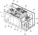
먼저, 도 1을 참조하면, 후드 겸용 전자레인지는 본체(10)에 의해 그 외관이 형성된다. 상기 본체(10)는 내부 공간을 가지는 직육면체의 형태로 이루어진다. 그 하방에는 다른 형태의 조리기기가 설치된다. First, referring to FIG. 1, an outer appearance of a hood-use microwave oven is formed by a
상기 본체(10)는 다른 형태의 조리기기 상측에 설치된다. 그 이유는 하측에서 발생하는 배기가스를 내부 공간으로 흡입하여 외부 공간으로 배기하는 후드 기능을 수행하기 위함이다.The
상기 본체(10)의 전면에는 도어(20)가 회동 가능하게 설치된다. 상기 도어(20)의 전면에는 사용자의 파지를 위한 핸들(21)이 제공된다. A
상기 도어(20)는 전체적으로 일정 정도의 두께를 가지는 사각판재 형태로 이루어진다. 상기 도어(20)에 의해 상기 본체(10)의 내부 공간에 위치하는 조리실(도 2의 30)을 선택적으로 개폐할 수 있게 된다. The
상기 조리실(30)은 상기 도어(20)에 선택적으로 개폐되면서 음식물이 요리되는 공간을 제공하게 된다. 상기, 조리실(30)의 내부 공간은 실질적으로 음식물이 요리되는 공간이 된다. The
상기 도어(20)의 우측에는 컨트롤패널(41)이 위치된다. 상기 컨트롤패널(41)에는 사용자가 음식물의 조리를 위한 조작신호를 입력하는 다수의 스위치와 같은 입력부가 제공된다. 또한, 상기 컨트롤패널(41)에는 상기 본체(10)의 동작 정보와, 음식물의 요리 정보 등도 표시된다. A
상기 컨트롤패널(41)은 일정 정도의 두께를 가지면서 세로 방향으로 긴 육면체 형상으로 이루어진다. 상기 컨트롤패널(41)의 내부 공간에는 다수의 제어부품이 고정되면서 표면에 다양한 회로가 인쇄되어 있는 회로기판이 위치된다. 상기 회로기판과 전장부품이 연결되면서, 사용자의 조작 신호에 의해 전장부품이 동작하게 된다. The
상기 본체(10)의 전면 상단부에는 벤트그릴(77)이 위치된다. 상기 벤트그릴(77)은 본체(10)의 내, 외부 공간으로 공기가 출입하는 통로를 제공한다. A
도 2를 참조하면, 상기 전장실(40)은 상기 조리실(30)의 우측에 위치된다. 이러한 전장실(40)의 내부에는 다수의 전장 부품이 설치된다. 전장실(40)의 내부에는 고주파를 발생시키는 마그네트론(42)과, 상기 마그네트론(42)으로 고전압의 전류를 제공하기 위하여 공급되는 전류를 고전압으로 변환하는 고전압변환기(43)와, 상기 고전압변환기(43)로 일정한 전압의 전류를 공급하는 커패시터(44) 등이 설치된다. 그리고 상기 전장실(40)의 전면에 실질적으로 상기 컨트롤패널(41)이 위치된다. Referring to FIG. 2, the
한편 상기 본체(10)의 전면을 전면패널(11)이 형성한다. 그리고, 상기 본체(10)의 후면을 후면패널(12)이 형성하고, 상기 본체(10)의 상면 및 양 측면을 상부패널(13)이 형성한다. 상기 전면패널(11), 후면패널(12) 및 상부패널(13)이 서로 고정되어 상기 본체(10)의 외형을 형성한다. On the other hand, the
상기 전면패널(11)은 전체적으로 소정의 두께를 가지면서 강도를 가지는 재질, 예를 들어 금속 재질로 이루어진다. 상기 컨트롤패널(41) 및 상기 벤트그릴(77)에 대응하는 상기 전면패널(11)의 일부분은 절개된다. The
상기 상부패널(13)에는 상기 본체(10) 내부 공간의 공기가 실외 공간으로 배출되는 실외배출구(131)가 형성된다. The
또한, 상기 본체(10)의 내부에는 상부플레이트(15)가 구비된다. 상기 상부플레이트(15)는 실질적으로 상기 조리실(30) 및 전장실(40)의 상면을 형성한다. 또한 상기 상부플레이트(15)는 상기 조리실(30) 및 전장실(40)과 후술할 배기공간(71) 및 제2흡입공간(73)을 구획한다고도 할 수 있다. In addition, an
상기 상부플레이트(15)에는 배기구(도 4의 19)가 구비된다. 상기 배기구(19)는 상기 조리실(30)의 내부로 흡입된 공기가 외부로 배출되는 출구역할을 한다.The
그리고, 상기 본체(10)의 내부에는 측면플레이트(17)와 하부플레이트(18)가 제공된다. 상기 측면플레이트(17)는 상기 조리실(30)의 양 측면을 형성한다. 상기 측면플레이트(17) 중 도면상 좌측의 것은 상기 상부패널(13)과의 사이에 다른 조리기기의 연소가스가 유동하는 유로를 형성한다. 또한, 상기 측면플레이트(17) 중 도면상 우측의 것은 실질적으로 상기 조리실(30)과 전장실(40)을 구획한다. Inside the
상기 하부플레이트(18)는 상기 조리실(30) 및 전장실(40)의 저면을 형성한다. 상기 하부플레이트(18)는 상기 상부플레이트(15)와 평행된다. 상기 하부플레이트(18)의 상면에는 상기 측면플레이트(17)의 하단이 고정된다. 또한 실질적으로 상기 하부플레이트(18)는 후술할 송풍팬(50)의 구동에 의하여 상기 본체(10)의 내부로 흡입되는 연소가스가 유동하는 유로를 상기 조리실(30) 및 전장실(40)과 구획하는 역할을 한다. The lower plate (18) forms the bottom surface of the cooking chamber (30) and the electric field chamber (40). The lower plate (18) is parallel to the upper plate (15). The lower end of the
상기 전장실(40)의 후단에는 구획플레이트(46)가 위치된다. 상기 구획플레이트(46)는 상기 후면패널(12)의 전면으로부터 소정의 간격만큼 전방으로 이격되게 위치한다. 따라서, 상기 구획플레이트(46)와 후면패널(12)의 사이에는 상기 송풍팬(50)의 구동에 의해 상기 본체(10)의 내부로 흡입되는 연소가스가 유동하는 유로 가 형성된다. 또한 실질적으로 상기 구획플레이트(46)에 의하여 상기 전장실(40) 및 후술할 제2흡입공간(73)과 상기 구획플레이트(46) 및 후면패널(12) 사이의 유로가 구획된다고도 할 수 있다. A partition plate (46) is located at the rear end of the electric field chamber (40). The
한편 상기 전면패널(11)의 상단부에는 실내배출구(74), 및 상기 제1실내흡입구(75), 제2실내흡입구(76)가 형성된다. 상기 실내배출구(74), 및 상기 제1실내흡입구(75), 제2실내흡입구(76)는 상기 전면패널(11)의 상단부 일부가 절개되어 형성된다. 상기 실내배출구(74)는 전면패널(11)의 상단부 중앙에 위치한다. 상기 제1실내흡입구(75)와 제2실내흡입구(76)는 실내배출구(74)를 기준으로 좌측과 우측에 위치된다. Meanwhile, an
상기 실내배출구(74)는 상기 본체(10)의 내부에서 외부로 공기가 배출되는 출구 역할을 한다. 그리고, 상기 제1 및 제2실내배출구(75,76)는 본체(10)의 외부에서 내부로 공기가 흡입되는 입구 역할을 한다. The indoor discharge port (74) serves as an outlet through which air is discharged from the inside of the main body (10) to the outside. The first and second
상기 실내배출구(74)의 후방에 형성되는 공간은 배기공간(71)이 된다. 상기 배기공간(71)은 실질적으로 실내배출구(74)를 통하여 상기 본체(10)의 내부 공간에서 주방 공간으로 배출되는 공기가 유동하는 공간이다. The space formed behind the indoor discharge port (74) becomes the exhaust space (71). The
상기 배기공간(71)의 양측 즉, 상기 제1 및 제2실내흡입구(75,76)의 후방에 형성되는 공간은 제1 및 제2흡입공간(72,73)이 된다. 상기 제1 및 제2흡입공간(72,73)은 실질적으로 상기 제1 및 제2실내흡입구(75,76)를 통하여 상기 본체(10)의 외부 공간에서 내부 공간으로 흡입되는 공기가 유동하는 공간이다. The space formed on both sides of the
상기 배기공간(71)에는 송풍팬(50)이 설치된다. 상기 송풍팬(50)은 크로스플 로우팬이 사용될 수 있다. 물론, 송풍팬(50)으로 다른 종류의 팬이 사용될 수도 있으나, 공간의 활용 및 공기의 유동 공간을 고려할 때 크로스플로우 팬이 가장 바람직하다. A ventilation fan (50) is installed in the exhaust space (71). The blowing
상기 송풍팬(50)은 후드 기능을 위한 공기의 유동과, 상기 본체(10)의 내부 공간에 제공되는 부품의 냉각을 위한 공기 유동을 발생시킨다. 다시 말해서, 상기 송풍팬(50)은 후드 기능을 위한 공기의 유동과, 냉각 기능을 위한 공기의 유동을 발생시킨다. The blowing
보다 상세하게는, 상기 송풍팬(50)은 상기 조리기기에서 발생하는 배기가스를 상기 본체(10)의 내부 공간으로 흡입한다. 그리고, 상기 송풍팬(50)은, 상기 본체(10)의 내부로 흡입되어 상기 본체(10)의 내부의 유로(즉, 상기 하부플레이트(18) 및 하면패널(14) 사이 공간, 상기 구획플레이트(46) 및 후면패널(12) 사이의 공간 및 상기 측면플레이트(17) 및 상기 상부패널(13) 사이 공간)를 차례로 유동하도록 하고, 다시 상기 배기공간(71)을 유동하여 상기 실내배출구(74)를 통하여 배출되거나, 상기 실외배출구(131)를 통하여 실외로 배출되는 공기의 흐름을 형성한다. More specifically, the blowing
또한, 상기 송풍팬(50)은 상기 제1실내흡입구(75)를 통하여 흡입되고, 상기 제1흡입공간(72)을 유동하면서 부품을 냉각시킨 후 상기 배기공간(71)을 유동하여 상기 실내배출구(74)를 통해 배출되거나, 상기 실외배출구(131)를 통해 배출되는 공기의 흐름을 형성한다. The blowing
상기 전장실(40)의 상방에 해당하는 상기 상부플레이트(15)의 일측에는 냉각 팬(45)이 설치된다. 상기 냉각팬(45)은 전장실(40)에 설치되는 전장 부품의 냉각을 위한 공기 흐름을 형성한다. A cooling fan (45) is installed on one side of the upper plate (15) corresponding to the upper part of the electric field chamber (40). The cooling fan (45) forms an air flow for cooling electric components installed in the electric component chamber (40).
더욱 상세하게는, 상기 냉각팬(45)은, 상기 제2실내흡입구(76)를 통해 흡입되어 상기 제2흡입공간(73)을 유동한 후 상기 전장실(40) 내부의 전장부품을 냉각하는 공기의 흐름을 형성한다. 또한, 상기 냉각팬(45)은, 상기 전장실(40) 내부의 전장부품을 냉각시킨 후 상기 조리실(30)로 전달되어 상기 배기구(19)를 통하여 상기 조리실(30) 외부로 배출되는 공기의 흐름을 형성한다.More specifically, the cooling
도 3을 참조하면, 상기 배기공간(71)에는 배기덕트(80)가 설치된다. 상기 배기덕트(80)는 실질적으로 상기 배기공간(71)을 공기가 유동하는 공간과 부품이 설치되는 공간으로 구획하는 역할을 한다. Referring to FIG. 3, an exhaust duct 80 is installed in the
상기 배기덕트(80)는 내열성을 가지는 재질, 예를 들면, 내열성 고분자화합물의 재질로 이루어진다. 상기 배기덕트(80)는 대략 "H" 형상의 종단면을 가지는 다면체형상으로 형성될 수 있다. The exhaust duct 80 is made of a material having heat resistance, for example, a material of a heat-resistant polymer compound. The exhaust duct 80 may be formed in a polyhedral shape having an approximately "H" vertical profile.
따라서, 상기 배기덕트(80)에 의해 상기 배기공간(71)이 2개의 공간 즉, 상기 상부플레이트(15)와 배기덕트(80) 사이의 공간 및 배기덕트(80)와 상기 상부패널(13) 사이 공간으로 구획된다.The space between the
그리고, 상기 상부플레이트(15)와 상기 배기덕트(80) 사이에 해당하는 공간에는 부품이 설치되고, 배기덕트(80)와 상부패널(13) 사이에 해당하는 공간은 공기의 유동이 이루어지는 유로의 역할을 수행한다. The space between the
또한, 상기 배기덕트(80)의 저면에는 설치개구(80a)가 형성된다. 상기 설치 개구(80a)는 배기덕트(80)의 저면 일부가 절제되어 형성된다. 이러한 설치개구(80a)는 후술할 램프(85)의 설치를 위한 것이다. 상기 설치개구(80a)는 덕트커버(81)에 의해 선택적으로 개폐될 수 있다. An installation opening 80a is formed in the bottom surface of the exhaust duct 80. [ The installation opening 80a is formed by cutting off a part of the bottom surface of the exhaust duct 80. The installation opening 80a is for installing the
한편, 상기 배기덕트(80)에는 분리부재(87)가 구비된다. 상기 분리부재(87)는 상기 상부플레이트(15)와 배기덕트(80) 사이의 공간을 2개의 공간으로 구획한다. 이때, 상기 분리부재(87)에 의하여 구획되는 2개의 공간이 상기 설치개구(80a)와 연통된다. Meanwhile, the exhaust duct 80 is provided with a separating member 87. The separating member 87 divides the space between the
한편, 상기 상부플레이트(15)와 상기 배기덕트(80) 사이의 공간, 실질적으로 배기덕트(80)의 하방에 해당하는 상부플레이트(15)에는 다수의 부품이 설치된다. 본 실시 예에서는 상부플레이트(15)와 배기덕트(80) 사이의 공간에는 스터러장치 및 상기 램프(85)가 위치된다. A plurality of parts are provided on the
이때, 상기 스터러장치 및 상기 램프(85)는 상기 분리부재(87)에 의하여 구획되는 공간에 각각 위치된다. 즉, 상기 스터러장치는 상기 분리부재(87)에 의하여 구획되는 공간 중 도면상 우측의 공간에 위치되고, 상기 램프(85)는 상기 분리부재(87)에 의해 구획되는 공간 중 도면상 좌측 공간에 위치된다. 따라서, 상기 램프(85)는 실질적으로 상기 설치개구(80a)를 통하여 상기 배기덕트(80)의 상방으로 노출될 수 있다. At this time, the stirrer device and the
한편, 상기 배기덕트(80)에는 배기가이드(84)가 설치된다. 상기 배기가이드(84)는 상기 배기구(19)를 통하여 상기 조리실(30)의 외부로 배출되는 공기가 상기 실내배기구(74)를 통하여 배출되도록 안내한다. On the other hand, the exhaust duct 80 is provided with an
따라서, 상기 배기가이드(84)는 실질적으로 상기 배기덕트(80)의 상방에 해당하는 공간을 유동하는 공기와 상기 배기구(19)를 통하여 배출되는 공기를 구획한다고 할 수 있다. 상기 배기가이드(84)는 예를 들면, 배기구(19)의 상방에 해당하는 배기덕트(80)에 일체로 형성될 수 있다. Accordingly, the
한편, 상기 상부플레이트(15)와 상기 배기덕트(80) 사이의 공간, 실질적으로 배기덕트(80)의 하방에 해당하는 상부플레이트(15)에는 다수의 부품이 설치된다. 본 실시 예에서는 상부플레이트(15)와 배기덕트(80) 사이의 공간에는 스터러장치 및 램프(85)가 위치된다. A plurality of parts are provided on the
이때, 상기 스터러장치 및 상기 램프(85)는 상기 분리부재(87)에 의하여 구획되는 공간에 각각 위치된다. 즉, 스터러장치는 분리부재(87)에 의하여 구획되는 공간 중 도면상 우측의 공간에 위치되고, 상기 램프(85)는 분리부재(87)에 의해 구획되는 공간 중 도면상 좌측 공간에 위치된다. 따라서, 상기 램프(85)는 실질적으로 상기 설치개구(80a)를 통하여 상기 배기덕트(80)의 상방으로 노출될 수 있다. At this time, the stirrer device and the
더욱 상세하게는, 상기 스터러장치는, 상기 조리실(30)의 내부로 조사되는 고주파를 난반사시키는 역할을 한다. 이러한 스터러장치는, 조리실(30)과 연통되는 소정의 공간을 형성하는 스터러커버(83), 상기 스터러커버(83)의 내부에 설치되어 고주파의 난반사를 위하여 회전하는 스터러팬(미도시) 및 상기 스터러커버(83)의 외부에 설치되어 상기 스터러팬의 구동을 위한 구동력을 제공하는 스터러팬모터(82)를 포함한다. 실질적으로 상기 스터러팬모터(82)가 상기 상부플레이트(15) 및 상기 배기덕트(80) 사이의 공간으로 노출된다.More specifically, the stirrer device diffusively reflects high-frequency waves radiated to the inside of the
그리고, 상기 제1흡입공간(72)에는 컨벡션장치(60)가 설치된다. 상기 컨벡션 장치(60)는 상기 조리실(30)의 내부의 공기를 가열하여 순환시키는 역할을 한다. 도 4 내지 도 6을 참조하면, 상기 컨벡션장치(60)는, 컨벡션커버(62), 컨벡션팬(63), 컨벡션모터(61) 및 컨벡션히터(64)를 포함한다.A
상기 컨벡션커버(62)는 상기 상부플레이트(15)의 상면에 고정된다. 상기 컨벡션커버(62)는 저면이 개구되는 다면체형상으로 형성된다. 상기 컨벡션챔버(62)는 상기 상부플레이트(15)의 상면에 형성되는 컨벡션배기구(65)와 컨벡션흡기구(66)를 차폐한다.The
상기 컨벡션흡기구(65) 및 컨벡션배기구(66)는 서로 소정의 거리만큼 이격된다. 상기 컨벡션흡기구(65)는 상기 컨벡션커버(62)의 내부, 실질적으로는, 상기 상부플레이트(15) 및 컨벡션커버(62) 사이의 공간으로 상기 조리실(30)의 내부의 공기가 흡입되는 입구역할을 한다. The
그리고 상기 컨벡션배기구(66)는, 상기 컨벡션커버(62)의 내부의 공기가 상기 조리실(30)의 내부로 배출되는 출구역할을 한다.The
상기 컨벡션팬(63)은 상기 컨벡션흡기구(65)의 상방에 해당하는 상기 컨벡션커버(62)의 내부에 위치된다. 상기 컨벡션팬(63)은 상기 컨벡션흡기구(65)를 통하여 상기 조리실(30)의 내부에서 상기 컨벡션커버(62)의 내부로 흡입되고, 다시 상기 컨벡션배기구(66)을 통하여 상기 컨벡션커버(62)의 내부에서 상기 조리실(30)의 내부로 배출되는 공기의 유동을 형성한다.The
상기 컨벡션모터(61)는 상기 컨벡션팬(63)의 회전을 위한 구동력을 제공한 다. 상기 컨벡션모터(61)는 상기 컨벡션커버(62)의 외부, 즉 상기 컨벡션커버(62)의 상면에 설치되어 상기 제1흡입공간(72) 상에 노출된다.The
상기 컨벡션히터(64)는 상기 컨벡션팬(63)의 구동에 의하여 상기 조리실(30)의 내부에서 상기 컨벡션챔버(62)의 내부로 흡입되는 공기를 가열하는 역할을 한다. 예를 들면, 상기 컨벡션히터(64)는 상기 컨벡션팬(63)의 테두리를 따라서 설치될 수 있다. The
한편, 상기 상부플레이트(15)에는 온도감지부(90)가 설치된다. 상기 온도감지부(90)는 전자레인지의 이상 여부, 예를 들면, 즉 상기 마그네트론(42)이나 컨벡션장치(60)와 같은 가열원의 과열여부를 감지하기 위한 것이다. On the other hand, the
본 실시예에서는, 상기 온도감지부(90)가 상기 배기구(19), 컨벡션흡기구(65) 및 컨벡션배기구(66)를 통하여 입출되는 공기의 온도를 감지한다. 예를 들면, 상기 온도감지부(90)로는, 감지한 온도가 상기 안전온도를 초과하는지 여부를 감지하는 써모스텟이 사용될 수 있다.In the present embodiment, the
이를 위하여 상기 온도감지부(90)는 상기 상부플레이트(15)와 접하도록 설치된다. 따라서 상기 온도감지부(90)는, 상기 배기구(19)를 통하여 상기 조리실(30)의 외부로 배출되는 공기의 온도, 상기 컨벡션흡기구(65)를 통하여 상기 컨벡션커버(62)의 내부로 흡입되는 공기의 온도, 및 상기 컨벡션배기구(66)를 통하여 상기 조리실(30)의 내부로 배출되는 공기의 온도를 상기 상부플레이트(15)를 통하여 전도받아서 감지한다. For this, the
그리고 상기 온도감지부(90)는 브라켓(91)에 의하여 상기 상부플레이트(15) 의 상면에 고정된다. 이때 상기 온도감지부(90)는 상기 브라켓(91)에 끼움 결합에 의해 결합될 수 있다.The
한편 도 6을 참조하면, 상기 온도감지부(90)는 아래의 조건을 모두 만족하도록 위치된다. On the other hand, referring to FIG. 6, the
(1) A < B + C (1) A < B + C
(2) B < C + A (2) B < C + A
(3) C < A + B(3) C < A + B
여기서 A는 상기 온도감지부(90)로부터 상기 배기구(19)까지의 최단거리이고, B는 상기 온도감지부(90)로부터 상기 컨벡션흡기구(65)까지의 최단거리이며, C는 상기 온도감지부(90)로부터 상기 컨벡션배기구(66)까지의 최단거리이다. Where A is the shortest distance from the
즉, 상기 온도감지부(90)는 상기 배기구(19), 컨벡션흡기구(65) 및 컨벡션배기구(66) 중 어느 하나까지의 최단거리가 나머지까지의 최단거리의 합 미만이 되도록 위치된다고 할 수 있다. That is, the
이는 상기 온도감지부(90)가, 상기 배기구(19), 컨벡션흡기구(65) 및 컨벡션배기구(66) 중 어느 하나를 통하여 입출되는 공기의 온도가 상기 안전온도를 초과하면, 전자레인지가 이상인 것으로 판단하기 위함이다.This is because if the temperature detected by the
예를 들면, 상기 온도감지부(90)가 상기 배기구(19) 및 컨벡션배기구(66)에 비하여 상기 컨벡션흡기구(65)로부터 과도하게 이격되게 위치될 수 있다. 이와 같은 경우에는, 상기 온도감지부(90)는 상기 컨벡션흡기구(65)를 통하여 입출되는 공기의 온도가 상기 안전온도를 초과하는 경우에도, 이를 감지할 수 없게 된다. For example, the
따라서 실제 전자레인지에 이상이 발생되었지만, 상기 온도감지부(90)가 이를 감지하지 못함으로써, 전자레인지가 과열되거나 나아가 전자레인지에 화재가 발생될 수 있다. Therefore, although an actual microwave oven has an abnormality, the
이에 따라 본 실시예에서는, 상기 온도감지부(90)가, 상술한 바와 같은 부등식을 만족하도록 위치됨으로써, 상기 배기구(19), 컨벡션흡기구(65) 및 컨벡션배기구(66)를 통하여 입출되는 공기의 온도 중 어느 하나의 온도가 설정된 안전온도를 초과하는지 여부를 감지할 수 있게 된다.Accordingly, in the present embodiment, since the
이하에서는 본 발명에 의한 후드 겸용 전자레인지의 실시예의 작용을 보다 상세하게 설명한다.Hereinafter, the operation of the embodiment of the microwave oven combined with the hood according to the present invention will be described in more detail.
먼저 상기 마그네트론(42)이 동작하여 상기 조리실(30)의 내부에서 음식물의 조리가 이루어진다. 한편 상기 마그네트론(42)이 동작하면, 상기 냉각팬(45)도 동작하여 상기 마그네트론(42)을 포함하는 전장부품의 냉각이 이루어진다. 그리고 상기 전장부품을 냉각시킨 공기는 상기 조리실(30)의 내부로 전달되고, 상기 배기구(19)를 통하여 상기 조리실(30)의 외부로 배출된다.First, the
한편 상기 마그네트론(42)의 동작과 함께 상기 컨벡션장치(60)가 동작될 수 있다. 따라서 상기 컨벡션모터(61)에 상기 컨벡션팬(63)이 회전하면, 상기 컨벡션흡기구(65) 및 컨벡션배기구(66)를 통한 상기 조리실(30)과 상기 컨벡션커버(62) 사이의 공기의 입출이 이루어진다.Meanwhile, the
그리고 상기 온도감지부(90)가, 상기 흡기구(19), 컨벡션흡기구(65) 및 컨벡션배기구(66)를 통하여 입출되는 공기의 온도를 통하여 전자레인지의 이상 여부를 감지한다. The
그런데 상술한 바와 같이, 본 실시예에서는, 상기 온도감지부(90)가 상기 배기구(19), 컨벡션흡기구(65) 및 컨벡션배기구(66)를 통하여 입출되는 공기 중 어느 하나의 온도가 상기 안전온도를 초과하더라도 이를 감지할 수 있게 된다. 따라서 상기 온도감지부(90)에 의하여 보다 정확하게 전자레인지의 이상 여부를 감지할 수 있게 된다.As described above, in the present embodiment, the
또한 상기 온도감지부(90)에 의하여 전자레인지의 이상 여부가 감지되면, 마이컴(미도시)이 전자레인지에 공급되는 전원을 차단한다. 따라서 전자레인지의 과열이나 전자레인지에 발생되는 화재 등을 방지할 수 있게 된다.Further, when the abnormality of the microwave oven is detected by the
상기한 바와 같은 구성을 가지는 본 발명에 의한 후드 겸용 전자레인지에 의하면, 조리실의 비정상 상태와 컨벡션장치의 비정상 상태를 가장 적합한 위치에서 감지하는 것이 가능하여 사용자의 안전성을 보장하게 됨으로써 제품 사용에 따른 안전성이 향상되는 효과를 기대할 수 있게 된다. According to the present invention, it is possible to detect the abnormal state of the cooking chamber and the abnormal state of the convection device at the most suitable position, thereby assuring the safety of the user, Can be expected to be improved.
이러한 효과를 가지는 본 발명에 의한 후드 겸용 전자레인지에 의하면 조리기기 산업에 그 이용 가능성이 크다 할 것이다. According to the microwave oven combined with a hood according to the present invention having such an effect, it is highly likely to be used in the cooking appliance industry.
도 1 은 본 발명의 실시 예에 의한 후드 겸용 전자레인지가 설치된 상태를 나타낸 설치도. BRIEF DESCRIPTION OF THE DRAWINGS Fig. 1 is an installation view showing a state in which a hood-use microwave oven according to an embodiment of the present invention is installed.
도 2 는 본 발명이 실시 예에 의한 후드 겸용 전자레인지의 도어와 컨트롤패널이 제거된 상태를 나타낸 사시도. 2 is a perspective view showing a state in which a door and a control panel of a hood and a microwave oven according to an embodiment of the present invention are removed.
도 3 은 본 발명의 실시 예에 의한 후드 겸용 전자레인지의 상부 구성을 나타낸 부분 절개 사시도. 3 is a partially cutaway perspective view showing an upper structure of a combined microwave oven according to an embodiment of the present invention.
도 4 는 본 발명의 실시 예에 의한 후드 겸용 전자레인지의 배기덕트가 제거된 상태를 나타낸 부분 확대 사시도. 4 is a partially enlarged perspective view showing a state in which an exhaust duct of a microwave oven combined with a hood according to an embodiment of the present invention is removed.
도 5 는 본 발명의 실시 예에 의한 후드 겸용 전자레인지의 배기덕트와 컨벡션장치 커버가 제거된 상태를 나타낸 부분 확대 사시도. 5 is a partially enlarged perspective view showing a state in which an exhaust duct and a convection device cover of a microwave oven combined with a hood according to an embodiment of the present invention are removed.
도 6 은 본 발명의 실시 예에 의한 후드 겸용 전자레인지의 온도감지부가 설치된 상태를 나타낸 부분 확대 사시도.6 is a partially enlarged perspective view showing a state in which the temperature sensing unit of the microwave oven combined with the hood according to the embodiment of the present invention is installed.
도 7 은 본 발명의 다른 실시 예에 의한 후드 겸용 전자레인지의 온도감지부가 설치된 상태를 나타낸 부분 확대 사시도.7 is a partially enlarged perspective view showing a state in which a temperature sensing unit of a microwave oven combined with a hood according to another embodiment of the present invention is installed.
Claims (9)
Priority Applications (1)
| Application Number | Priority Date | Filing Date | Title |
|---|---|---|---|
| KR1020090127301A KR101625679B1 (en) | 2009-12-18 | 2009-12-18 | Microwave oven having hood |
Applications Claiming Priority (1)
| Application Number | Priority Date | Filing Date | Title |
|---|---|---|---|
| KR1020090127301A KR101625679B1 (en) | 2009-12-18 | 2009-12-18 | Microwave oven having hood |
Publications (2)
| Publication Number | Publication Date |
|---|---|
| KR20110070470A KR20110070470A (en) | 2011-06-24 |
| KR101625679B1 true KR101625679B1 (en) | 2016-05-30 |
Family
ID=44401976
Family Applications (1)
| Application Number | Title | Priority Date | Filing Date |
|---|---|---|---|
| KR1020090127301A Active KR101625679B1 (en) | 2009-12-18 | 2009-12-18 | Microwave oven having hood |
Country Status (1)
| Country | Link |
|---|---|
| KR (1) | KR101625679B1 (en) |
Families Citing this family (3)
| Publication number | Priority date | Publication date | Assignee | Title |
|---|---|---|---|---|
| CN102997294A (en) * | 2011-09-13 | 2013-03-27 | 乐金电子(天津)电器有限公司 | Convective microwave oven |
| CN102997295B (en) * | 2011-09-13 | 2016-07-06 | 乐金电子(天津)电器有限公司 | Convection-microwave oven |
| CN105066192B (en) * | 2015-08-20 | 2017-10-24 | 宁波方太厨具有限公司 | A kind of thermometric micro-wave oven and operation control method |
Citations (2)
| Publication number | Priority date | Publication date | Assignee | Title |
|---|---|---|---|---|
| JP2000065356A (en) * | 1998-08-24 | 2000-03-03 | Osaka Gas Co Ltd | Cooking range |
| KR200229347Y1 (en) * | 2000-12-20 | 2001-07-19 | 엘지전자 주식회사 | A over the range |
-
2009
- 2009-12-18 KR KR1020090127301A patent/KR101625679B1/en active Active
Patent Citations (2)
| Publication number | Priority date | Publication date | Assignee | Title |
|---|---|---|---|---|
| JP2000065356A (en) * | 1998-08-24 | 2000-03-03 | Osaka Gas Co Ltd | Cooking range |
| KR200229347Y1 (en) * | 2000-12-20 | 2001-07-19 | 엘지전자 주식회사 | A over the range |
Also Published As
| Publication number | Publication date |
|---|---|
| KR20110070470A (en) | 2011-06-24 |
Similar Documents
| Publication | Publication Date | Title |
|---|---|---|
| US6621058B1 (en) | Wall-mounted microwave oven with air curtain guide | |
| EP1439740B1 (en) | Wall-mounted type microwave oven | |
| EP1243164B1 (en) | Built-in microwave oven | |
| US7296565B2 (en) | Cooling apparatus of cooking appliance | |
| US20240015859A1 (en) | Cooking device | |
| KR101625679B1 (en) | Microwave oven having hood | |
| EP2235445B1 (en) | A microwave oven | |
| KR100402587B1 (en) | Air flow system for microwave oven | |
| KR20220136027A (en) | Qooking apparatus | |
| KR100402578B1 (en) | An air flow system for micro wave oven | |
| KR20010064859A (en) | Built-in type microwave oven | |
| KR101627379B1 (en) | Microwave oven having hood | |
| KR102850857B1 (en) | Microwave oven having hood | |
| KR100633173B1 (en) | Electric room structure of electric oven | |
| JP5011001B2 (en) | Cooker | |
| KR101665697B1 (en) | Microwave oven having hood | |
| KR101652999B1 (en) | Microwave oven having hood | |
| KR200232523Y1 (en) | Structure of ventilation of cavity for microwave oven | |
| JP2003074865A (en) | Combined cooking appliance | |
| JP5542563B2 (en) | Cooker | |
| KR20050077334A (en) | Wall mounted type microwave oven | |
| KR101634808B1 (en) | Microwave oven having hood | |
| KR100650565B1 (en) | Cooling structure of hood and microwave oven | |
| JP6840109B2 (en) | Induction heating cooker | |
| KR200189009Y1 (en) | Device for ventilating cavity air for microwave oven |
Legal Events
| Date | Code | Title | Description |
|---|---|---|---|
| PA0109 | Patent application |
St.27 status event code: A-0-1-A10-A12-nap-PA0109 |
|
| PG1501 | Laying open of application |
St.27 status event code: A-1-1-Q10-Q12-nap-PG1501 |
|
| R17-X000 | Change to representative recorded |
St.27 status event code: A-3-3-R10-R17-oth-X000 |
|
| A201 | Request for examination | ||
| PA0201 | Request for examination |
St.27 status event code: A-1-2-D10-D11-exm-PA0201 |
|
| PN2301 | Change of applicant |
St.27 status event code: A-3-3-R10-R13-asn-PN2301 St.27 status event code: A-3-3-R10-R11-asn-PN2301 |
|
| R17-X000 | Change to representative recorded |
St.27 status event code: A-3-3-R10-R17-oth-X000 |
|
| D13-X000 | Search requested |
St.27 status event code: A-1-2-D10-D13-srh-X000 |
|
| D14-X000 | Search report completed |
St.27 status event code: A-1-2-D10-D14-srh-X000 |
|
| E902 | Notification of reason for refusal | ||
| PE0902 | Notice of grounds for rejection |
St.27 status event code: A-1-2-D10-D21-exm-PE0902 |
|
| P11-X000 | Amendment of application requested |
St.27 status event code: A-2-2-P10-P11-nap-X000 |
|
| P13-X000 | Application amended |
St.27 status event code: A-2-2-P10-P13-nap-X000 |
|
| E701 | Decision to grant or registration of patent right | ||
| PE0701 | Decision of registration |
St.27 status event code: A-1-2-D10-D22-exm-PE0701 |
|
| GRNT | Written decision to grant | ||
| PR0701 | Registration of establishment |
St.27 status event code: A-2-4-F10-F11-exm-PR0701 |
|
| PR1002 | Payment of registration fee |
St.27 status event code: A-2-2-U10-U11-oth-PR1002 Fee payment year number: 1 |
|
| PG1601 | Publication of registration |
St.27 status event code: A-4-4-Q10-Q13-nap-PG1601 |
|
| PR1001 | Payment of annual fee |
St.27 status event code: A-4-4-U10-U11-oth-PR1001 Fee payment year number: 4 |
|
| PR1001 | Payment of annual fee |
St.27 status event code: A-4-4-U10-U11-oth-PR1001 Fee payment year number: 5 |
|
| PN2301 | Change of applicant |
St.27 status event code: A-5-5-R10-R13-asn-PN2301 St.27 status event code: A-5-5-R10-R11-asn-PN2301 |
|
| PR1001 | Payment of annual fee |
St.27 status event code: A-4-4-U10-U11-oth-PR1001 Fee payment year number: 6 |
|
| PR1001 | Payment of annual fee |
St.27 status event code: A-4-4-U10-U11-oth-PR1001 Fee payment year number: 7 |
|
| PR1001 | Payment of annual fee |
St.27 status event code: A-4-4-U10-U11-oth-PR1001 Fee payment year number: 8 |
|
| PR1001 | Payment of annual fee |
St.27 status event code: A-4-4-U10-U11-oth-PR1001 Fee payment year number: 9 |
|
| PR1001 | Payment of annual fee |
St.27 status event code: A-4-4-U10-U11-oth-PR1001 Fee payment year number: 10 |
|
| PR1001 | Payment of annual fee |
St.27 status event code: A-4-4-U10-U11-oth-PR1001 Fee payment year number: 11 |
|
| U11 | Full renewal or maintenance fee paid |
Free format text: ST27 STATUS EVENT CODE: A-4-4-U10-U11-OTH-PR1001 (AS PROVIDED BY THE NATIONAL OFFICE) Year of fee payment: 11 |