KR101617254B1 - Wireless Signal Transmitter-Receiver - Google Patents
Wireless Signal Transmitter-Receiver Download PDFInfo
- Publication number
- KR101617254B1 KR101617254B1 KR1020080088710A KR20080088710A KR101617254B1 KR 101617254 B1 KR101617254 B1 KR 101617254B1 KR 1020080088710 A KR1020080088710 A KR 1020080088710A KR 20080088710 A KR20080088710 A KR 20080088710A KR 101617254 B1 KR101617254 B1 KR 101617254B1
- Authority
- KR
- South Korea
- Prior art keywords
- housing
- wireless signal
- reflection plate
- radio signal
- display device
- Prior art date
- Legal status (The legal status is an assumption and is not a legal conclusion. Google has not performed a legal analysis and makes no representation as to the accuracy of the status listed.)
- Expired - Fee Related
Links
Images


Classifications
-
- H—ELECTRICITY
- H04—ELECTRIC COMMUNICATION TECHNIQUE
- H04B—TRANSMISSION
- H04B1/00—Details of transmission systems, not covered by a single one of groups H04B3/00 - H04B13/00; Details of transmission systems not characterised by the medium used for transmission
- H04B1/38—Transceivers, i.e. devices in which transmitter and receiver form a structural unit and in which at least one part is used for functions of transmitting and receiving
-
- H—ELECTRICITY
- H04—ELECTRIC COMMUNICATION TECHNIQUE
- H04B—TRANSMISSION
- H04B10/00—Transmission systems employing electromagnetic waves other than radio-waves, e.g. infrared, visible or ultraviolet light, or employing corpuscular radiation, e.g. quantum communication
- H04B10/11—Arrangements specific to free-space transmission, i.e. transmission through air or vacuum
Landscapes
- Engineering & Computer Science (AREA)
- Computer Networks & Wireless Communication (AREA)
- Signal Processing (AREA)
- Physics & Mathematics (AREA)
- Electromagnetism (AREA)
- Aerials With Secondary Devices (AREA)
- Transceivers (AREA)
Abstract
본 발명은 무선신호 송수신기에 관한 것이다. 보다 상세하게, 디스플레이장치 및 무선신호 송수신기의 설치 위치에 따라 선택적으로 무선신호를 반사시켜, 무선신호 송수신기에서 디스플레이장치 등에 도달하는 무선신호의 도달거리를 최소화할 수 있는 무선신호 송수신기에 관한 것이다.The present invention relates to a radio signal transceiver. And more particularly, to a wireless signal transceiver capable of selectively minimizing a reach of a wireless signal transmitted from a wireless signal transceiver to a display device by selectively reflecting a wireless signal according to an installation position of a display device and a wireless signal transceiver.
무선, 디스플레이장치, 반사, HD Wireless, display device, reflection, HD
Description
본 발명은 무선신호 송수신기에 관한 것이다. 보다 상세하게, 디스플레이장치 및 무선신호 송수신기의 설치 위치에 따라 선택적으로 무선신호를 반사시켜, 무선신호 송수신기에서 디스플레이장치 등에 도달하는 무선신호의 도달거리를 최소화할 수 있는 무선신호 송수신기에 관한 것이다.The present invention relates to a radio signal transceiver. And more particularly, to a wireless signal transceiver capable of selectively minimizing a reach of a wireless signal transmitted from a wireless signal transceiver to a display device by selectively reflecting a wireless signal according to an installation position of a display device and a wireless signal transceiver.
디스플레이장치는 유선 방송, VHS, DVD 또는 AUDIO 시스템 등과 연결되어 영상신호 또는 음향신호를 수신하고, 영상과 음향을 사용자에게 제공한다.The display device is connected to a wired broadcast, a VHS, a DVD, or an audio system to receive a video signal or an audio signal, and provides video and sound to a user.
이와 같이, 유선 방송, VHS, DVD 또는 AUDIO 시스템 등과 연결되어 영상신호 또는 음향신호를 수신하고, 영상과 음향을 사용자에게 제공하기 위하여, 디스플레이장치는 유선으로 VHS, DVD 또는 AUDIO 시스템 등과 연결된다.In this way, the display device is connected to a VHS, a DVD, or an AUDIO system in a wired manner in order to receive a video signal or an audio signal in connection with a cable broadcasting, a VHS, a DVD or an AUDIO system and provide an image and sound to a user.
그러므로, 다양한 외부 기기와 연결되기 위해서는 연결되는 외부 기기의 숫자만큼의 케이블이 디스플레이장치와 연결되어야 한다.Therefore, in order to connect with various external devices, a number of cables connected to the external devices must be connected to the display device.
그러나, 외부기기와 디스플레이장치를 무선으로 연결하는 방식이 소개되고 있다. 즉, 외부기기에서 디스플레이장치로 영상신호를 무선으로 전송하는 기술이 사용되고 있다.However, a method of wirelessly connecting an external device and a display device has been introduced. That is, a technique of wirelessly transmitting a video signal from an external device to a display device is used.
즉, 다양한 외부기기를 하나의 무선신호 송수신기와 유무선으로 연결하고, 상기 무선신호 송수신기는 상기 디스플레이장치와 무선으로 신호를 송수신할 수 있게 된다.That is, various external devices are connected to one radio signal transceiver through wired / wireless lines, and the radio signal transceiver can wirelessly transmit / receive signals to / from the display device.
이와 같은 무선전송을 가능하게 하는 방법으로 IEEE 802.11n 방식 또는 UWB 방식이 사용되며, 이와 같은 IEEE 802.11n 방식 또는 UWB 방식은 방사형 전파 발생 으로 수신거리가 길며(약 20m) 방사형 전파로 인해 비교적 신호 수신에 제한이 적다는 장점이 있으나, 풀 HD(Full High Definition) 디스플레이장치와 같이, 풀 HD 영상을 제공하기 위한 고용량 데이터 전송은 불가능하다는 단점이 있다.The IEEE 802.11n or UWB scheme is used as a method for enabling such wireless transmission. The IEEE 802.11n scheme or the UWB scheme is a scheme in which a reception distance is long (about 20 m) due to the generation of a radial wave, There is a disadvantage that high capacity data transmission is not possible in order to provide a full HD image like a full high definition display device.
전술한 종래 무선방식의 한계를 극복하기 위하여, 고대역 60Ghz 주파수를 갖는 전파를 사용하여 고용량 데이터의 송수신이 가능하게 되었다. 60Ghz의 고대역 주파수를 사용하면, 풀 HD(Full High Definition) 영상구현을 위한 영상신호 전송 및 기타 고용량 데이터 전송 가능하다.In order to overcome the limitations of the conventional radio system described above, it has become possible to transmit and receive high capacity data by using radio waves having a high frequency of 60 GHz. Using high-bandwidth frequencies of 60 GHz, video signal transmission and other high-capacity data transmission for full high definition (HD) imaging is possible.
그러나, 고대역 주파수의 특성상 고대역 주파수를 갖는 전파의 직진성 및 무선신홍의 도달거리가 약 100미터(m) 이하라는 단점으로 인해 수신영역의 제한이 많다.However, due to the characteristics of the high-frequency frequency, there is a limitation in the reception area due to the disadvantage that the directivity of the radio wave having the high-band frequency and the reaching distance of the radio new Hong are less than about 100 meters (m).
특히, 무선신호 송수신기와 디스플레이장치가 서로 마주보는 위치에 배치되는 경우보다, 디스플레이장치의 하부에 무선신호 송수신기가 위치되는 경우가 많을 것이다. 예를 들면, 거실 등의 일측 벽면에 디스플레이장치가 설치되고 무선신호 송수신기를 포함하는 각종 외부기기들은 그 주변(예를 들면, 디스플레이장치의 하부)에 설치되는 경우가 많을 것이다.In particular, a radio signal transceiver may be located at a lower portion of the display device than in a case where the radio signal transceiver and the display device are disposed at positions facing each other. For example, in many cases, a display device is installed on one side wall of a living room or the like, and various external devices including a wireless signal transceiver are installed around the periphery (for example, a lower portion of the display device).
즉, 무선신호의 송수신칩이 장착된 수신모듈은 디스플레이장치의 전면에 장착되고, 상기 무선신호 송수신기에서 송출된 무선신호는 반대편 벽면 등에 반사되는 방법으로 상기 무손신호 수신칩에 도달될 것이다.That is, a receiving module equipped with a transmitting / receiving chip of a wireless signal is mounted on the front surface of a display device, and a wireless signal transmitted from the wireless signal transceiver will reach the wireless signal receiving chip in such a way that the wireless signal is reflected on the opposite wall surface or the like.
그러나, 전술한 바와 같이 고대역 주파수의 특성상 전파의 도달범위가 짧으므로 일측 벽면에 디스플레이장치가 설치되고 무선신호 송수신기를 포함하는 각종 외부기기들은 그 주변(예를 들면, 디스플레이장치의 하부)에 설치되는 경우와 같이, 전파가 반대 벽면에서의 반사과정을 겪으며 도달되는 경우(총 10미터 이상의 도달거리)에 발생될 수 있는 전파의 송수신 문제를 해결하기 위한 방법이 필요하다.However, as described above, due to the nature of the high-frequency frequency, the range of arrival of the radio wave is short, so that a display device is installed on one side wall and various external devices including a radio signal transceiver are installed around the periphery There is a need for a method for solving the problems of transmission and reception of radio waves that can occur when the radio wave is reached through a process of reflection on the opposite wall surface (reaching distance of 10 meters or more in total).
본 발명은 다양한 외부기기에서 제공되는 신호를 고대역 주파수를 갖는 무선신호를 이용하여 디스플레이장치로 전송하는 무선신호 송수신기의 무선신호의 도달거리를 단축하고, 디스플레이장치 등이 수신하는 무신신호의 감도를 개선할 수 있는 무선신호 송수신기를 제공하는 것을 해결하고자 하는 기술적인 과제로 한다.The present invention reduces the arrival distance of a wireless signal of a wireless signal transceiver that transmits a signal provided from various external devices to a display device using a wireless signal having a high band frequency and reduces the sensitivity of the wireless signal received by a display device or the like The present invention provides a radio signal transceiver capable of improving the communication quality of a radio signal.
본 발명은 상기 과제를 해결하기 위하여, 외형을 이루는 하우징, 상기 하우징의 전면방향으로 무선신호를 송신하거나 상기 하우징의 전면방향으로 도달되는 무선신호를 수신하며, 상기 하우징에 장착되는 무선신호 송수신칩 및, 상기 무선신호 송수신칩에서 송신되는 무선신호를 상기 하우징의 전면방향 이외의 방향으로 반사시키도록 선택적으로 상기 무선신호 송수신칩 전면에 이격된 상태로 변위되는 반사판, 을 포함하는 무선신호 송수신기를 제공한다.According to an aspect of the present invention, there is provided a wireless signal transmitting / receiving chip for receiving a radio signal transmitted in a front direction of the housing or a front direction of the housing, And a reflection plate that is selectively displaced from the front surface of the radio signal transmitting / receiving chip so as to reflect the radio signal transmitted from the radio signal transmitting / receiving chip in a direction other than the front direction of the housing .
이 경우, 상기 반사판은 상기 하우징에 회동가능하게 장착될 수 있다.In this case, the reflection plate may be rotatably mounted on the housing.
그리고, 상기 반사판과 그 일단이 연결된 레버를 포함하며, 상기 반사판은 상기 하우징에 형성된 삽입홈에 선택적으로 삽입되고, 상기 레버는 상기 하우징의 측면에 힌지축에 의해 회전가능하게 결합될 수 있다.The reflector may be selectively inserted into an insertion groove formed in the housing, and the lever may be rotatably coupled to a side surface of the housing by a hinge shaft.
여기서, 상기 레버의 타단에 손잡이가 더 구비될 수 있다.Here, a handle may be further provided at the other end of the lever.
또한, 상기 삽입홈은 상기 하우징의 전면과 상기 레버가 결합된 상기 하우징의 측면에 형성된 개구부와 그 개구부 내측으로 형성된 공간일 수 있다.The insertion groove may be an opening formed in a front surface of the housing and a side surface of the housing coupled with the lever, and a space formed inside the opening.
이 경우, 상기 삽입홈을 형성하는 공간은 수평방향으로 형성될 수 있다.In this case, the space for forming the insertion groove may be formed in the horizontal direction.
그리고, 상기 반사판은 선택적으로 상기 하우징 내부에 삽입되거나, 상기 하우징 외부로 인출되도록 상기 하우징에 진퇴 이동가능하게 장착될 수 있다.The reflection plate may be selectively inserted into the housing or may be retractably mounted on the housing to be drawn out of the housing.
여기서, 상기 하우징과 상기 반사판을 연결하는 지지부재가 더 구비되고, 상기 지지부재와 상기 반사판과 힌지결합될 수 있다.Here, a support member for connecting the housing and the reflector may be further provided, and the support member may be hinged to the reflector.
또한, 상기 반사판과 상기 지지부재는 상기 무선신호 송수신칩 하부에서 삽입 또는 인출되며, 상기 반사판은 인출된 후 상기 무선신호 송수신칩 전면 방향으로 회전될 수 있도록 힌지결합될 수 있다.In addition, the reflection plate and the support member may be inserted or withdrawn from below the radio signal transmission / reception chip, and the reflection plate may be hinged so as to be rotated in the front direction of the radio signal transmission / reception chip after being drawn out.
이 경우, 상기 반사판은 경사진 상태로 상기 하우징에 삽입 또는 상기 하우징으로부터 인출될 수 있다.In this case, the reflection plate may be inserted into or pulled out of the housing in an inclined state.
여기서, 상기 반사판은 금속으로 구성되거나 상기 반사판은 금속재질로 코팅될 수 있다.Here, the reflection plate may be made of metal, or the reflection plate may be coated with a metal material.
또한, 상기 무선신호 송수신칩은 50Ghz 내지 70Ghz 사이의 주파수 대역을 갖는 영상정보가 포함된 무선신호를 송신 또는 수신할 수 있다.The wireless signal transmitting / receiving chip may transmit or receive a wireless signal including image information having a frequency band of 50 GHz to 70 GHz.
본 발명에 따른 무선신호 송수신기에 의하면, 다양한 외부기기에서 제공되는 신호를 고대역 주파수를 갖는 무선신호를 이용하여 디스플레이장치로 전송하는 무선신호 송수신기의 무선신호의 도달거리를 단축할 수 있다.The wireless signal transceiver according to the present invention can shorten the reach of a wireless signal of a wireless signal transceiver that transmits a signal provided from various external devices to a display device using a wireless signal having a high band frequency.
또한, 본 발명에 따른 무선신호 송수신기에 의하면, 디스플레이장치 등이 수신하는 무신신호의 감도를 개선할 수 있다.In addition, according to the wireless signal transceiver according to the present invention, the sensitivity of a wireless signal received by a display device or the like can be improved.
또한, 본 발명에 따른 무선신호 송수신기에 의하면, 무선신호 송수신기와 디스플레이장치의 설치위치의 제약을 줄일 수 있다.In addition, according to the radio signal transceiver according to the present invention, it is possible to limit the installation position of the radio signal transceiver and the display device.
이하, 첨부된 도면들을 참조하여 본 발명의 바람직한 실시예들을 상세히 설명하기로 한다. 그러나, 본 발명은 여기서 설명된 실시예들에 한정되지 않고 다른 형태로 구체화될 수도 있다. 오히려, 여기서 소개되는 실시예들은 개시된 내용이 철저하고 완전해질 수 있도록, 그리고 당업자에게 본 발명의 사상이 충분히 전달될 수 있도록 하기 위해 제공되어지는 것이다. 명세서 전체에 걸쳐서 동일한 참조번호들은 동일한 구성요소들을 나타낸다.Hereinafter, preferred embodiments of the present invention will be described in detail with reference to the accompanying drawings. However, the present invention is not limited to the embodiments described herein but may be embodied in other forms. Rather, the embodiments disclosed herein are provided so that this disclosure will be thorough and complete, and will fully convey the concept of the invention to those skilled in the art. Like reference numerals designate like elements throughout the specification.
도 1은 본 발명에 따른 무선신호 송수신기(100)와 디스플레이장치(300)의 사시도이다. 상기 디스플레이장치(300)는 영상이 표시되는 패널(320), 상기 패널(320)을 수용하는 하우징(310), 상기 하우징(310) 내부에 장착되며, 무선신호 송수신기(100)에서 송출된 무선신호를 수신하는 수신칩(210)이 장착되는 회로기판(220)이 구비된다. 상기 무선신호를 수신하는 무선신호 수신칩(210)이 장착된 회로기판(220)은 하나의 수신모듈(200)로 구성될 수 있다. 즉, 디스플레이장치(300)의 주된 회로기판과 별개로 무선신호를 수신하기 위한 모듈로서 디스플레이장치에 구비될 수 있다.1 is a perspective view of a
디스플레이장치(300)에 장착되는 무선신호 수신칩(210)은 디스플레이장치(300)의 전면 하우징(310) 내부에 장착될 수 있다. 전면 하우징(310)은 일반적으로 플라스틱 재질로 구성될 수 있다. 상기 디스플레이장치(300)에서 신호의 무선전 송을 위해 사용하는 전파는 50Ghz 내지 70Ghz 정도의 주파수(예를 들면, 60Ghz)를 갖는 고대역 전파가 사용될 수 있다.The wireless signal receiving
이러한 고대역 주파수는 다음과 같은 투과 특성을 갖는다. 상기 고대역 주파수를 갖는 전파는 유리 재질은 그 입사각에 따라서 투과율이 결정되며, 목재의 경우는 그 내부에 함유된 수분 함량에 따라 반사 또는 투과한다.These high frequency frequencies have the following transmission characteristics. The transmittance of the radio wave having the high frequency is determined according to the incident angle of the glass material, and in the case of the wood, it is reflected or transmitted according to the moisture content contained therein.
그리고, 상기 고대역 주파수를 갖는 전파는 금속재질의 경우에는 투과하지 못하고 반사되는 특징을 갖는다.In addition, the radio wave having the high-band frequency is characterized by being reflected without being transmitted in the case of a metal material.
반면에, 플라스틱은 투과할 수 있으며 플라스틱에 칠해지는 페인트에 따라 반사할 수도 있다.On the other hand, plastics can penetrate and reflect on the paint painted on plastic.
따라서, 도 1에 도시된 상기 패널(320)을 감싸는 디스플레이장치(300)의 하우징(310)이 플라스틱으로 제공된다면, 상기 무선신호 송수신기(100)에서 송신되는 무선신호는 상기 하우징(310)을 투과하여 상기 하우징(310) 내부에 위치하는 상기 무선신호 수신칩(210)에 도달할 수 있다.Accordingly, if the
물론, 상기 디스플레이장치(300)의 하우징(310)에 상기 수신칩(210)이 노출되도록 개구부를 형성하여 수신칩(210)이 노출되도록 할 수 있으나, 하우징(310)의 미적 마감을 고려하는 경우 상기 수신칩(210)이 상기 하우징(310) 내부에 매립될 수 있다.Of course, an opening may be formed in the
전술한 고대역 주파수를 갖는 전파특성에 따라 플라스틱 하우징(310)은 관통하여 상기 무선신호 수신칩(210)에 도달할 수 있으나, 전술한 바와 같이, 고대역 주파수는 전파의 직진성 및 도달거리의 짧음으로 인하여, 전파의 도달범위가 제한 적이다.The
상기 디스플레이장치(300)는 본 발명에 따른 무선신호 송수신기(100)에서 송신된 영상신호를 수신하여 표시한다.The
상기 무선신호 송수신기(100)는 영상신호를 제공할 수 있는 다양한 외부기기와 연결될 수 있다.The
상기 무선신호 송수신기(100)는 상기 외부기기로부터 수신된 영상신호를 무선신호로 변환시켜 송신하거나, 무선신호를 수신하는 기능을 수행할 수 있다. 상기 무선신호 송수신기(100)에서 송신된 무선신호는 디스플레이장치의 무선신호 송수신칩(310)로부터 전파되는데, 이미 기술한 바와 같이 풀 HD(Full High Definition) 영상신호 등을 전송하기 위한 고대역(예를 들면, 60Ghz) 주파수를 갖는 전파를 사용할 수 있다.The
본 발명에 따른 상기 무선신호 송수신기(100)는 상기 무선신호 송수신칩(110)에서 송신되는 무선신호를 상기 하우징의 전면방향 이외의 방향으로 반사시키도록 선택적으로 상기 무선신호 송수신칩(110) 전면에 이격된 상태로 변위되는 반사판(120)을 포함한다는 특징을 갖는다.The
상기 반사판은 상기 무선신호 송수신칩(110)에서 송신되어 상기 디스플레이장치(300)에 도달하는 무선신호의 도달거리를 줄이는 역할을 한다.The reflection plate serves to reduce a reaching distance of a radio signal transmitted from the radio signal transmitting / receiving
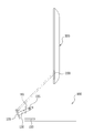
도 2는 본 발명에 따른 무선신호 송수신기(100)와 상기 디스플레이장치(300) 사이에서 무선신호의 반사과정을 도시하는 개념도이다.FIG. 2 is a conceptual diagram illustrating a process of reflecting a radio signal between the
이미 기술한 바와 같이, 상기 무선신호 송수신기(100)가 디스플레이장 치(300)과 대향하게 구비되는 경우가 아니라면, 상기 무선신호 송수신기(100)에서 송신되는 무선신호는 그 반대편 벽면 등에 반사되어 상기 디스플레이장치(300)에 도달한다.The wireless signal transmitted from the
그러나, 전파의 직진성과 전파의 도달거리가 짧다는 특성으로 인하여, 무선신호 송수신기에서 송출된 무선신호가 상기 디스플레이장치(300)에 도달하지 못할 수 있다.However, the radio signal transmitted from the radio signal transceiver may not reach the
따라서, 도 3에 도시된 바와 같이 상기 무선신호 송수신기(100) 상부 또는 하부에 디스플레이장치(300)가 구비되는 경우에 상기 무선신호 송수신기(100)에서 송신되는 무선신호를 반사시켜 무선신호의 도달거리를 단축시키는 반사판(120)이 구비된다.3, when the
상기 반사판(120)은 상기 무선신호 송수신칩(110)에서 송신되는 무선신호를 상기 하우징의 전면방향 이외의 방향으로 반사시키도록 선택적으로 상기 무선신호 송수신칩(110) 전면에 이격된 상태로 변위된다.The
도 2에 도시된 실시예에서, 상기 반사판을 상기 무선신호 송수신칩(110)에서 송신되는 무선신호를 상기 하우징의 전면방향 이외의 방향으로 반사시키도록 선택적으로 상기 무선신호 송수신칩(110) 전면에 이격된 상태로 변위시키는 방법은 상기 반사판(120)을 무선신호 송수신기(100) 하우징에 회동가능하게 장착하는 방법이다.2, the reflection plate is selectively disposed on the front surface of the wireless signal transmitting /
상기 반사판(120)의 일단에 레버(130)가 구비되며, 상기 반사판(120)은 상기 하우징에 형성된 삽입홈(150)에 선택적으로 삽입되고, 상기 레버(130)는 상기 하우 징의 측면에 힌지축(135)에 의해 회전가능하게 결합된다.A
따라서, 회전가능한 상기 레버(130)에 의해 상기 반사판(120)은 상기 무선신호 송수신칩(110)에서 송신되는 무선신호를 상기 무선신호 송수신기(100)의 상부에 구비된 디스플레이장치(300)의 무선신호 수신칩이 장착된 무선신호 수신모듈(200) 방향으로에 반사시킬 수 있다.Therefore, the
상기 힌지축(135)에 회전가능하게 결합된 상기 레버(130)는 상기 반사판(120)이 상기 무선신호 송수신칩(110)에서 송신되는 무선신호를 상기 무선신호 송수신기의 상방향 또는 하방향으로 반사시킬 수 있다.The
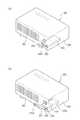
도 3은 본 발명에 따른 무선신호 송수신기(100)의 반사판(120)의 회전상태에 따른 사시도를 도시한다.3 is a perspective view illustrating a rotation state of the
구체적으로 도 3(a)는 상기 반사판(120)이 상기 무선신호 송수신기(100)의 하우징에 형성된 삽입홈(150)에 삽입된 상태를 도시하며, 도 3(b)는 상기 반사판(120)이 상기 무선신호 송수신칩(110)에서 송신되는 무선신호를 상기 하우징의 전면방향 이외의 방향으로 반사시키도록 선택적으로 상기 무선신호 송수신칩(110) 전면에 이격된 상태로 회전된 상태를 도시한다.3 (a) shows a state where the
도 3(b)에 도시된 실시예에서, 상기 반사판(120)이 다양한 각도로 회전될 수 있음을 설명하기 위한 것으로서, 그 회전각도는 디스플레이장치의 위치에 따라서 다양하게 가변될 수 있다.In the embodiment shown in FIG. 3 (b), the
상기 삽입홈(150)은 무선신호 송수신기(100) 하우징의 전면(101)과 상기 레버가 힌지축(135)에 의해 결합된 상기 하우징의 측면(102)에 형성된 개구부(101a, 102a)와 그 개구부 내측으로 형성된 공간이며, 상기 삽입홈(150)은 대략 수평방향으로 형성될 수 있다.The
상기 레버(130)의 일단은 상기 반사판(120)의 측면에 연결되며, 상기 힌지축(135)과 연결된 그 타단에 손잡이(140)가 형성될 수 있다. 또한, 상기 힌지축(135)는 상기 반사판(120)의 회전각도가 조절된 뒤, 조절된 각도가 유지될 수 있을 정도의 마찰력이 작용하도록 마찰링(미도시) 등이 구비될 수 있다.One end of the
상기 마찰링에 의한 마찰력은 상기 반사판(120)이 각도 조절된 뒤, 조절된 각도가 유지될 수 있을 정도이면 되므로, 회전각도를 조절하기 어려울 정도로 마찰력이 제공되면 안된다.The frictional force by the friction ring may be such that the angle of the
이러한 마찰력의 조절은 상기 힌지축(135)의 체결강도를 조절하는 방법에 의하여 조절이 가능하다.The frictional force can be controlled by adjusting the fastening strength of the
상기 반사판(120)은 상기 무선신호 송수신칩(110)에서 송신되는 고대역 무선신호를 반사시켜야 한다.The
상기 반사판(120)는 상기 고대역 주파수를 갖는 전파들이 투과되지 못하도록 금속 재질로 구성될 수 있다. 만일 상기 반사부재(230)가 플라스틱 재질로 구성된다면 그 표면에 상기 고대역 주파수가 반사될 수 있는 금속성 물질 등으로 코팅될 수 있다.The
도 4는 본 발명에 따른 무선신호 송수신기(100)의 다른 실시예를 도시한다. 도 4에 도시된 실시예에서, 상기 무선신호 송수신칩(110)에서 송신된 무선신호를 반사시키는 반사판(120)은 상기 무선신호 송수신기(100) 하우징에 삽입되거나, 상 기 하우징 외부로 인출되도록 상기 하우징에 진퇴 이동가능하게 장착될 수 있다.Figure 4 illustrates another embodiment of a
도 4에 도시된 바와 같이, 상기 반사판(120)은 상기 무선신호 송수신기(100) 하우징에서 진퇴 이동가능하게 장착된다. 상기 반사판(120)은 상기 무선신호 송수신기(100) 하우징에서 인출된 상태에서 회전이 가능하도록 장착된다.As shown in FIG. 4, the
도 4(a)는 상기 반사판(120)이 상기 하우징 내부에 삽입된 상태를 도시하며, 도 4(b)는 상기 반사판(120)이 인출된 상태에서 회전된 상태를 도시한다.4 (a) shows a state in which the
상기 반사판(120)은 별도의 지지부재(125)와 힌지결합될 수 있다. 상기 삽입홈(150a)은 상기 하우징의 전면에 형성된 개구부에서 내측으로 수평하게 형성된 공간일 수 있다.The
상기 반사판(120)은 상기 하우징에 형성된 삽입홈(150a)에 삽입되는 경우, 상기 지지부재(125)와 수평하게 전개된 상태에서 삽입 또는 인출될 수 있다.When the
상기 반사판(120)과 상기 지지부재(125)는 힌지(123)에 의하여 회전가능하게 결합되며, 상기 삽입홈(150a)에서 인출되는 범위는 상기 반사판(120)과 상기 힌지(123)이 외부로 노출될 수 있을 정도로 인출되는 것이 바람직하다.The
상기 반사판(120)과 상기 힌지(123)는 외부로 노출되어야 상기 반사판(120)이 상기 지지부재(125)에 대하여 힌지(123)를 회전축으로 회전가능 해야하기 때문이다.This is because the
그리고, 상기 지지부재(125)는 상기 삽입홈(150a)에서 슬라이드 이동될 수 있으나 상기 하우징으로부터 분리되어서는 안된다. 따라서, 상기 지지부재(125)는 상기 삽입홈(150a)으로부터 분리되지 않도록 걸림턱(미도시) 등이 구비될 수 있다.The
그리고, 상기 반사판(120)에 반사판의 인출을 용이하게 할 수 있도록 링손잡이(140b) 등이 구비될 수 있다. 손잡이의 형태는 다양하게 변화될 수 있다. A
도 5는 본 발명에 따른 무선신호 송수신기(100)의 다른 실시예를 도시한다.Figure 5 illustrates another embodiment of a
도 5에 도시된 실시예의 반사판(120)은 도 4에 도시된 실시예와 마찬가지로, 상기 하우징에 형성된 삽입홈(150b)으로부터 진퇴 이동가능하게 삽입 또는 인출된다는 점은 공통되지만, 상기 삽입홈(150b)이 일정한 경사를 갖으며 기울어지도록 형성된다는 특징을 갖는다.The
도 5(b)에 도시된 바와 같이, 상기 반사판(120)의 일부는 상기 경사진 삽입홈(150b)에서 인출되면, 상기 무선신호 송수신칩(110)의 전면에 경사진 상태로 위치한다. 따라서, 상기 무선신호 송수신칩(110)에서 송신되는 무선신호는 상기 무선신호 송수신칩(110)의 전면에 위치한 반사판(120)에 반사되어 상기 무선신호 송수신기(100) 상부에 구비될 수 있는 디스플레이장치에 도달할 수 있으므로, 무선신호의 도달거리를 줄일 수 있다.As shown in FIG. 5 (b), when the part of the
또한, 도 5에 도시된 실시에에서, 상기 반사판(120)의 인출을 용이하게 하는 링손잡이(140b)가 구비될 수 있음은 도 4에 도시된 실시예와 마찬가지이다.In addition, in the embodiment shown in FIG. 5, the
도 3 내지 도 5에 도시된 실시예에서, 상기 반사판(120)은 회전 또는 인출되지 않으면, 무선신호 송수신기에서 송신되는 무선신호는 무선신호 송수신기 전면 방향으로 진행할 것이다.In the embodiment shown in FIGS. 3 to 5, if the
그러나, 상기 무선신호 송수신칩에서 송신되는 무선신호를 상기 하우징의 전면방향 이외의 방향으로 반사시키도록 선택적으로 상기 무선신호 송수신칩 전면에 이격된 상태로 변위되는 반사판을 사용하면, 무선신호 송수신기 상부에 위치하는 디스플레이장치에 무선신호를 반사시킬 수 있으므로, 무선신호의 도달거리를 단축할 수 있다.However, if a reflector is used that is selectively displaced in a state of being spaced apart from the front face of the radio signal transmitting / receiving chip so as to reflect the radio signal transmitted from the radio signal transmitting / receiving chip in a direction other than the front direction of the housing, It is possible to reflect the wireless signal to the display device in which the wireless communication device is located, thereby shortening the reach distance of the wireless signal.
상기 반사판(120)이 상기 무선신호 송수신칩(110) 전방에 위치하도록 선택적으로 변위될 수 있으므로, 사용자는 디스플레이장치 및 무선신호 송수신기의 위치에 따라 상기 반사판(120)을 회전 또는 인출하여, 무선신호를 반사시키거나 상기 반사반(120)을 상기 삽입홈에 삽입한 상태로 사용할 수 있다.The
본 명세서는 본 발명의 바람직한 실시예를 참조하여 설명하였지만, 해당 기술분야의 당업자는 이하에서 서술하는 특허청구범위에 기재된 본 발명의 사상 및 영역으로부터 벗어나지 않는 범위 내에서 본 발명을 다양하게 수정 및 변경 실시할 수 있을 것이다. 그러므로 변형된 실시가 기본적으로 본 발명의 특허청구범위의 구성요소를 포함한다면 모두 본 발명의 기술적 범주에 포함된다고 보아야 한다.While the present invention has been particularly shown and described with reference to preferred embodiments thereof, it will be understood by those skilled in the art that various changes and modifications may be made without departing from the spirit and scope of the invention as defined in the following claims. . It is therefore to be understood that the modified embodiments are included in the technical scope of the present invention if they basically include elements of the claims of the present invention.
도 1은 본 발명에 따른 무선신호 송수신기와 디스플레이장치의 사시도이다.1 is a perspective view of a radio signal transceiver and a display device according to the present invention.
도 2는 본 발명에 따른 무선신호 송수신기와 상기 디스플레이장치 사이에서 무선신호의 반사과정을 도시하는 개념도이다.2 is a conceptual diagram illustrating a process of reflecting a radio signal between a radio signal transceiver and the display device according to the present invention.
도 3은 본 발명에 따른 무선신호 송수신기의 반사판의 회전상태에 따른 사시도를 도시한다.FIG. 3 is a perspective view of the reflector of the radio signal transceiver according to the present invention.
도 4는 본 발명에 따른 무선신호 송수신기의 다른 실시예를 도시한다. 4 shows another embodiment of a radio signal transceiver according to the present invention.
도 5는 본 발명에 따른 무선신호 송수신기의 다른 실시예를 도시한다.5 shows another embodiment of a radio signal transceiver according to the present invention.
** 도면의 주요 부분에 대한 부호의 설명 **DESCRIPTION OF REFERENCE NUMERALS
100 : 무선신호 송수신기 110 : 무선신호 송수신칩100: radio signal transceiver 110: radio signal transmitting and receiving chip
120 : 반사판 125 : 지지부재120: reflector 125: support member
130 : 레버 135 : 힌지축130: lever 135: hinge shaft
150 : 장착홈150: mounting groove
Claims (13)
Priority Applications (1)
| Application Number | Priority Date | Filing Date | Title |
|---|---|---|---|
| KR1020080088710A KR101617254B1 (en) | 2008-09-09 | 2008-09-09 | Wireless Signal Transmitter-Receiver |
Applications Claiming Priority (1)
| Application Number | Priority Date | Filing Date | Title |
|---|---|---|---|
| KR1020080088710A KR101617254B1 (en) | 2008-09-09 | 2008-09-09 | Wireless Signal Transmitter-Receiver |
Publications (2)
| Publication Number | Publication Date |
|---|---|
| KR20100029981A KR20100029981A (en) | 2010-03-18 |
| KR101617254B1 true KR101617254B1 (en) | 2016-05-02 |
Family
ID=42180027
Family Applications (1)
| Application Number | Title | Priority Date | Filing Date |
|---|---|---|---|
| KR1020080088710A Expired - Fee Related KR101617254B1 (en) | 2008-09-09 | 2008-09-09 | Wireless Signal Transmitter-Receiver |
Country Status (1)
| Country | Link |
|---|---|
| KR (1) | KR101617254B1 (en) |
Citations (2)
| Publication number | Priority date | Publication date | Assignee | Title |
|---|---|---|---|---|
| JP2000353971A (en) * | 1999-04-05 | 2000-12-19 | Sharp Corp | Millimeter wave transmitter, millimeter wave receiver, repeater, and electronic equipment |
| JP2007060308A (en) * | 2005-08-24 | 2007-03-08 | Matsushita Electric Ind Co Ltd | Optical space transmission system |
-
2008
- 2008-09-09 KR KR1020080088710A patent/KR101617254B1/en not_active Expired - Fee Related
Patent Citations (2)
| Publication number | Priority date | Publication date | Assignee | Title |
|---|---|---|---|---|
| JP2000353971A (en) * | 1999-04-05 | 2000-12-19 | Sharp Corp | Millimeter wave transmitter, millimeter wave receiver, repeater, and electronic equipment |
| JP2007060308A (en) * | 2005-08-24 | 2007-03-08 | Matsushita Electric Ind Co Ltd | Optical space transmission system |
Also Published As
| Publication number | Publication date |
|---|---|
| KR20100029981A (en) | 2010-03-18 |
Similar Documents
| Publication | Publication Date | Title |
|---|---|---|
| JP4903471B2 (en) | Building wall material and wireless transmission system | |
| JP4649522B2 (en) | Notebook personal computer | |
| EP3449530B1 (en) | Antenna device and electronic device including the same | |
| JP2010118845A (en) | Millimeter wave transceiving system, and reflecting plate | |
| EP3618183B1 (en) | Vehicular antenna device | |
| KR20100127045A (en) | Tracking antenna device for 3 band satellite communication | |
| KR20100005099A (en) | Antenna system for receiving signals from satellites and method for driving the same | |
| US10868367B2 (en) | Antenna apparatus | |
| US20150333394A1 (en) | Device and method for surface positioning of antennas | |
| KR101617254B1 (en) | Wireless Signal Transmitter-Receiver | |
| CN110120578B (en) | 5G signal receiving antenna | |
| EP3398227B1 (en) | Systems, apparatus, and methods for selecting antennas | |
| US20090199246A1 (en) | Video data processing device and external transmitting or receiving device | |
| JP4734472B2 (en) | Electronics | |
| KR101567122B1 (en) | Enclosed reflector antenna mount | |
| US20060125699A1 (en) | Collapsible antenna device | |
| KR101107376B1 (en) | Transceiver for Display Devices | |
| NO864563L (en) | REFLECTOR ANTENNA WITH SELF-SUSTAINABLE MEASUREMENT ELEMENT. | |
| TWI536656B (en) | Display device with directional antenna | |
| US7042405B2 (en) | Planar satellite antenna and mobile electronic apparatus arrangement | |
| US20120034892A1 (en) | High-rate wireless receiving apparatus | |
| KR200356553Y1 (en) | The antenna | |
| CN103996356B (en) | Display device with directional antenna | |
| CN215070425U (en) | Thin high-gain broadband antenna | |
| US9437934B2 (en) | Device including reflective element to reflect directional wireless signals impinging thereon in a direction away from the device |
Legal Events
| Date | Code | Title | Description |
|---|---|---|---|
| PA0109 | Patent application |
St.27 status event code: A-0-1-A10-A12-nap-PA0109 |
|
| R18-X000 | Changes to party contact information recorded |
St.27 status event code: A-3-3-R10-R18-oth-X000 |
|
| R18-X000 | Changes to party contact information recorded |
St.27 status event code: A-3-3-R10-R18-oth-X000 |
|
| PG1501 | Laying open of application |
St.27 status event code: A-1-1-Q10-Q12-nap-PG1501 |
|
| A201 | Request for examination | ||
| PA0201 | Request for examination |
St.27 status event code: A-1-2-D10-D11-exm-PA0201 |
|
| E902 | Notification of reason for refusal | ||
| PE0902 | Notice of grounds for rejection |
St.27 status event code: A-1-2-D10-D21-exm-PE0902 |
|
| AMND | Amendment | ||
| E13-X000 | Pre-grant limitation requested |
St.27 status event code: A-2-3-E10-E13-lim-X000 |
|
| P11-X000 | Amendment of application requested |
St.27 status event code: A-2-2-P10-P11-nap-X000 |
|
| P13-X000 | Application amended |
St.27 status event code: A-2-2-P10-P13-nap-X000 |
|
| R17-X000 | Change to representative recorded |
St.27 status event code: A-3-3-R10-R17-oth-X000 |
|
| PN2301 | Change of applicant |
St.27 status event code: A-3-3-R10-R13-asn-PN2301 St.27 status event code: A-3-3-R10-R11-asn-PN2301 |
|
| E902 | Notification of reason for refusal | ||
| PE0902 | Notice of grounds for rejection |
St.27 status event code: A-1-2-D10-D21-exm-PE0902 |
|
| AMND | Amendment | ||
| E13-X000 | Pre-grant limitation requested |
St.27 status event code: A-2-3-E10-E13-lim-X000 |
|
| P11-X000 | Amendment of application requested |
St.27 status event code: A-2-2-P10-P11-nap-X000 |
|
| P13-X000 | Application amended |
St.27 status event code: A-2-2-P10-P13-nap-X000 |
|
| E601 | Decision to refuse application | ||
| PE0601 | Decision on rejection of patent |
St.27 status event code: N-2-6-B10-B15-exm-PE0601 |
|
| AMND | Amendment | ||
| E13-X000 | Pre-grant limitation requested |
St.27 status event code: A-2-3-E10-E13-lim-X000 |
|
| J201 | Request for trial against refusal decision | ||
| P11-X000 | Amendment of application requested |
St.27 status event code: A-2-2-P10-P11-nap-X000 |
|
| P13-X000 | Application amended |
St.27 status event code: A-2-2-P10-P13-nap-X000 |
|
| PJ0201 | Trial against decision of rejection |
St.27 status event code: A-3-3-V10-V11-apl-PJ0201 |
|
| PB0901 | Examination by re-examination before a trial |
St.27 status event code: A-6-3-E10-E12-rex-PB0901 |
|
| B701 | Decision to grant | ||
| PB0701 | Decision of registration after re-examination before a trial |
St.27 status event code: A-3-4-F10-F13-rex-PB0701 |
|
| GRNT | Written decision to grant | ||
| PR0701 | Registration of establishment |
St.27 status event code: A-2-4-F10-F11-exm-PR0701 |
|
| PR1002 | Payment of registration fee |
St.27 status event code: A-2-2-U10-U11-oth-PR1002 Fee payment year number: 1 |
|
| PG1601 | Publication of registration |
St.27 status event code: A-4-4-Q10-Q13-nap-PG1601 |
|
| PR1001 | Payment of annual fee |
St.27 status event code: A-4-4-U10-U11-oth-PR1001 Fee payment year number: 4 |
|
| PR1001 | Payment of annual fee |
St.27 status event code: A-4-4-U10-U11-oth-PR1001 Fee payment year number: 5 |
|
| P22-X000 | Classification modified |
St.27 status event code: A-4-4-P10-P22-nap-X000 |
|
| PN2301 | Change of applicant |
St.27 status event code: A-5-5-R10-R13-asn-PN2301 St.27 status event code: A-5-5-R10-R11-asn-PN2301 |
|
| PR1001 | Payment of annual fee |
St.27 status event code: A-4-4-U10-U11-oth-PR1001 Fee payment year number: 6 |
|
| PR1001 | Payment of annual fee |
St.27 status event code: A-4-4-U10-U11-oth-PR1001 Fee payment year number: 7 |
|
| PR1001 | Payment of annual fee |
St.27 status event code: A-4-4-U10-U11-oth-PR1001 Fee payment year number: 8 |
|
| PR1001 | Payment of annual fee |
St.27 status event code: A-4-4-U10-U11-oth-PR1001 Fee payment year number: 9 |
|
| PC1903 | Unpaid annual fee |
St.27 status event code: A-4-4-U10-U13-oth-PC1903 Not in force date: 20250427 Payment event data comment text: Termination Category : DEFAULT_OF_REGISTRATION_FEE |
|
| H13 | Ip right lapsed |
Free format text: ST27 STATUS EVENT CODE: N-4-6-H10-H13-OTH-PC1903 (AS PROVIDED BY THE NATIONAL OFFICE); TERMINATION CATEGORY : DEFAULT_OF_REGISTRATION_FEE Effective date: 20250427 |
|
| PC1903 | Unpaid annual fee |
St.27 status event code: N-4-6-H10-H13-oth-PC1903 Ip right cessation event data comment text: Termination Category : DEFAULT_OF_REGISTRATION_FEE Not in force date: 20250427 |