KR101578568B1 - Stamped beam connector - Google Patents
Stamped beam connector Download PDFInfo
- Publication number
- KR101578568B1 KR101578568B1 KR1020107019641A KR20107019641A KR101578568B1 KR 101578568 B1 KR101578568 B1 KR 101578568B1 KR 1020107019641 A KR1020107019641 A KR 1020107019641A KR 20107019641 A KR20107019641 A KR 20107019641A KR 101578568 B1 KR101578568 B1 KR 101578568B1
- Authority
- KR
- South Korea
- Prior art keywords
- array
- electrical connector
- flexible
- flexible beams
- beams
- Prior art date
- Legal status (The legal status is an assumption and is not a legal conclusion. Google has not performed a legal analysis and makes no representation as to the accuracy of the status listed.)
- Expired - Fee Related
Links
Images



Classifications
-
- H—ELECTRICITY
- H01—ELECTRIC ELEMENTS
- H01R—ELECTRICALLY-CONDUCTIVE CONNECTIONS; STRUCTURAL ASSOCIATIONS OF A PLURALITY OF MUTUALLY-INSULATED ELECTRICAL CONNECTING ELEMENTS; COUPLING DEVICES; CURRENT COLLECTORS
- H01R13/00—Details of coupling devices of the kinds covered by groups H01R12/70 or H01R24/00 - H01R33/00
- H01R13/02—Contact members
- H01R13/15—Pins, blades or sockets having separate spring member for producing or increasing contact pressure
- H01R13/187—Pins, blades or sockets having separate spring member for producing or increasing contact pressure with spring member in the socket
-
- H—ELECTRICITY
- H01—ELECTRIC ELEMENTS
- H01R—ELECTRICALLY-CONDUCTIVE CONNECTIONS; STRUCTURAL ASSOCIATIONS OF A PLURALITY OF MUTUALLY-INSULATED ELECTRICAL CONNECTING ELEMENTS; COUPLING DEVICES; CURRENT COLLECTORS
- H01R43/00—Apparatus or processes specially adapted for manufacturing, assembling, maintaining, or repairing of line connectors or current collectors or for joining electric conductors
- H01R43/16—Apparatus or processes specially adapted for manufacturing, assembling, maintaining, or repairing of line connectors or current collectors or for joining electric conductors for manufacturing contact members, e.g. by punching and by bending
-
- Y—GENERAL TAGGING OF NEW TECHNOLOGICAL DEVELOPMENTS; GENERAL TAGGING OF CROSS-SECTIONAL TECHNOLOGIES SPANNING OVER SEVERAL SECTIONS OF THE IPC; TECHNICAL SUBJECTS COVERED BY FORMER USPC CROSS-REFERENCE ART COLLECTIONS [XRACs] AND DIGESTS
- Y10—TECHNICAL SUBJECTS COVERED BY FORMER USPC
- Y10T—TECHNICAL SUBJECTS COVERED BY FORMER US CLASSIFICATION
- Y10T29/00—Metal working
- Y10T29/49—Method of mechanical manufacture
- Y10T29/49002—Electrical device making
- Y10T29/49117—Conductor or circuit manufacturing
- Y10T29/49204—Contact or terminal manufacturing
Landscapes
- Engineering & Computer Science (AREA)
- Manufacturing & Machinery (AREA)
- Coupling Device And Connection With Printed Circuit (AREA)
- Manufacturing Of Electrical Connectors (AREA)
Abstract
전기 커넥터는 후드 내에 중첩되고 정합 커넥터를 수용하기 위한 실질적으로 원통형인 공동을 형성하는 가요성 비임의 제1 및 제2 어레이를 포함한다. 각 가요성 비임의 접촉 영역은 다중 접촉 지점을 형성하도록 형상화될 수도 있어서, 이에 따라 전류가 통과할 수 있는 전체 영역을 증가시킨다.The electrical connector includes first and second arrays of flexible beams that overlap within the hood and form a substantially cylindrical cavity for receiving the mating connector. The contact area of each flexible beam may be shaped to form multiple contact points, thereby increasing the overall area through which the current can pass.
Description
본 발명은 전기 커넥터에 관한 것이다.The present invention relates to an electrical connector.
전기 커넥터는 전류가 전기 시스템의 부품들 사이에서 흐르도록 분리 가능한 경로를 제공하는데 사용된다. 많은 적용예에서, 부품들 사이의 다수의 연결은 주어진 전기 커넥터 내에 다수의 데이터 및/또는 전력 연결을 또한 필요로 할 수 있다. 최근에, 일반적인 전자 부품에 요구되는 연결의 개수가 증가되었고, 이는 더 많은 수의 전기 접속에 대한 요구를 또한 창출하였다. 또한, 전자 부품의 사이즈가 일반적으로 감소되었고, 이는 더 작은 전기 커넥터에 대한 요구를 창출하였다. 이들 각각이 성능에 대한 요구를 증가시킴에도 불구하고, 저렴한 커넥터에 대한 요구가 존재한다. 출원인은 비교적 작은 사이즈를 갖고 최소 손실로 전류를 전달할 수 있는 저렴한 전기 커넥터가 필요하다는 것을 알았다.The electrical connector is used to provide a detachable path for electrical current to flow between the components of the electrical system. In many applications, multiple connections between components may also require multiple data and / or power connections within a given electrical connector. Recently, the number of connections required for common electronic components has increased, which has also created a demand for a greater number of electrical connections. In addition, the size of electronic components has generally been reduced, which has created a demand for smaller electrical connectors. Despite each of these increasing demands on performance, there is a need for inexpensive connectors. Applicants have found that an inexpensive electrical connector is needed that has a relatively small size and can deliver current with a minimum loss.
본 발명의 일 태양에 따르면, 정합 커넥터와 결합하기 위한 전기 커넥터가 개시된다. 전기 커넥터는 기부로부터 연장되는 가요성 비임의 제1 어레이를 포함한다. 가요성 비임의 제1 어레이는 정합 커넥터를 수용하도록 구성되는 공동 주위에 배열된다. 가요성 비임의 제1 어레이의 말단부는 공동 내에 수용될 때 정합 커넥터와의 전기 접속을 제공하는 제1 세트의 접촉 지점을 형성하도록 공동을 향해 내향 연장된다. 가요성 비임의 제2 어레이가 기부로부터 연장되고, 가요성 비임의 제1 어레이의 내측에 포개진다(nested). 가요성 비임의 제2 어레이의 말단부는 공동 내에 수용될 때 정합 커넥터와의 전기 접속을 제공하는 제2 세트의 접촉 지점을 형성하도록 공동을 향해 내향 연장된다.According to one aspect of the invention, an electrical connector for coupling with a mating connector is disclosed. The electrical connector includes a first array of flexible beams extending from the base. A first array of flexible beams is arranged around the cavity configured to receive the mating connector. The distal end of the first array of flexible beams extends inwardly toward the cavity to form a first set of contact points that provide electrical connection with the mating connector when received within the cavity. A second array of flexible beams extends from the base and is nested inside the first array of flexible beams. The distal end of the second array of flexible beams extends inwardly toward the cavity to form a second set of points of contact that provide electrical connection with the mating connector when received within the cavity.
본 발명의 또 다른 태양에 따르면, 정합 커넥터에 연결되기 위한 전기 커넥터가 개시된다. 전기 커넥터는 기부로부터 연장되는 가요성 비임의 제1 어레이를 포함한다. 가요성 비임의 제1 어레이는 정합 커넥터를 수용하도록 구성되는 실질적으로 원통형인 공동 주위에 배열된다. 제1 어레이의 각 가요성 비임의 말단부는 공동을 향해 내향 연장되고, 공동 내에 수용될 때 정합 커넥터와의 전기 접속을 제공하도록 2개 이상의 접촉 지점을 형성하는 표면을 갖는 접촉 영역을 갖는다. 2개 이상의 접촉 지점은 실질적으로 원통형인 공동 주위를 회전하는 반경을 따라 서로 이격된다.According to another aspect of the present invention, an electrical connector for connection to a mating connector is disclosed. The electrical connector includes a first array of flexible beams extending from the base. The first array of flexible beams is arranged around a substantially cylindrical cavity configured to receive the mating connector. The distal end of each flexible beam of the first array extends inwardly toward the cavity and has a contact area having a surface defining two or more contact points to provide electrical connection with the mating connector when received within the cavity. The two or more contact points are spaced apart from one another along a radius of rotation about a substantially cylindrical cavity.
본 발명의 또 다른 태양에 따르면, 전기 커넥터를 형성하는 방법이 개시된다. 이 방법은 도전성 재료의 시트를 제공하는 단계를 포함한다. 시트의 일부가 가요성 비임의 제1 어레이를 가요성 비임의 제2 어레이로부터의 분리시키도록 랜싱 가공(lanced)된다. 가요성 비임의 제1 및 제2 어레이는 시트의 기부 부분을 통해 서로 연결되어 유지된다. 가요성 비임의 제1 어레이의 말단부가 제1 세트의 접촉 영역을 형성하도록 만곡된다. 가요성 비임의 제2 어레이의 말단부가 제2 세트의 접촉 영역을 형성하도록 만곡된다. 기부와 가요성 비임의 제1 및 제2 어레이는 정합 커넥터를 수용하도록 구성되는 실질적으로 원통형인 공동을 형성하도록 만곡된다.According to another aspect of the present invention, a method of forming an electrical connector is disclosed. The method includes providing a sheet of conductive material. A portion of the sheet is lanced to separate the first array of flexible beams from the second array of flexible beams. The first and second arrays of flexible beams are connected and held together through the base portion of the sheet. The distal ends of the first array of flexible beams are curved to form a first set of contact areas. The distal ends of the second array of flexible beams are curved to form a second set of contact areas. The first and second arrays of base and flexible beams are curved to form a substantially cylindrical cavity configured to receive the mating connector.
본 발명의 또 다른 실시예에 따르면, 전기 커넥터를 형성하는 방법이 개시된다. 이 방법은 도전성 재료의 제1 및 제2 시트부를 제공하는 단계를 포함한다. 제1 시트부는 연장되는 가요성 비임의 제1 어레이 및 제1 기부 부분을 형성하도록 블랭크 가공(blanked)된다. 제2 시트부는 연장되는 가요성 비임의 제2 어레이 및 제2 기부 부분을 형성하도록 블랭크 가공된다. 가요성 비임의 제1 어레이의 말단부가 제1 세트의 접촉 영역을 형성하도록 만곡되고, 가요성 비임의 제2 어레이의 말단부가 제2 세트의 접촉 영역을 형성하도록 만곡된다. 가요성 비임의 제1 및 제2 어레이는 정합 커넥터를 수용하도록 구성되는 실질적으로 원통형인 공동을 형성하도록 만곡된다. 가요성 비임의 제2 어레이는 가요성 비임의 제1 어레이에 포개진다.According to another embodiment of the present invention, a method of forming an electrical connector is disclosed. The method includes providing first and second sheet portions of conductive material. The first sheet portion is blanked to form a first array and a first base portion of the extending flexible beam. The second sheet portion is blanked to form a second array and a second base portion of the extending flexible beam. The distal ends of the first array of flexible beams are curved to form a first set of contact areas and the distal ends of the second array of flexible beams are curved to form a second set of contact areas. The first and second arrays of flexible beams are curved to form a substantially cylindrical cavity configured to receive the mating connector. The second array of flexible beams is superimposed on the first array of flexible beams.
첨부 도면은 일정한 축적으로 도시되도록 의도되지 않는다. 도면에서, 다양한 도면에 도시된 동일하거나 거의 동일한 각 구성 요소는 유사한 도면 부호로 표시된다. 명료성을 위해서, 모든 구성요소가 모든 도면에서 도면부호가 붙여지는 것은 아닐 수도 있다.
본 발명의 다양한 실시예는 이하에서 첨부된 도면들을 참조하여, 일례에 의해 이제 기술될 것이다.
도 1은 일 실시예에 따라 전기 커넥터의 개략적인 단면도를 도시한다.
도 2는 일 실시예에 따라 재료의 공통 시트로 형성되는 가요성 비임의 제1 및 제2 어레이를 갖는 전기 커넥터의 개략적인 단면도를 도시한다.
도 3은 일 실시예에 따라 제2 세트의 접촉 지점에 대해 엇갈리게 되어 있는 제1 세트의 접촉 지점의 개략적 도면을 도시한다.
도 4는 일 실시예에 따라, 가요성 비임의 접촉 영역을 포함하는 커넥터의 단부도와, 다중 접촉 지점을 갖는 하나의 접촉 영역의 확대 단면도를 도시한다.
도 5는 커넥터 및 정합 커넥터의 일 실시예의 접촉 지점들 사이의 상호작용의 개략적 도면을 도시한다.
도 6a 내지 도 6c는 다양한 제조 단계 동안 커넥터의 다양한 실시예의 구성요소를 도시한다.The accompanying drawings are not intended to be drawn to scale. In the drawings, the same or almost identical components shown in various drawings are denoted by similar reference numerals. For the sake of clarity, not all components may be referenced in all figures.
Various embodiments of the present invention will now be described, by way of example, with reference to the accompanying drawings, in which Fig.
1 shows a schematic cross-sectional view of an electrical connector according to one embodiment.
Figure 2 shows a schematic cross-sectional view of an electrical connector having a first and a second array of flexible beams formed of a common sheet of material in accordance with one embodiment.
Figure 3 shows a schematic view of a first set of points of contact staggered with respect to a second set of points of contact in accordance with one embodiment.
4 shows an enlarged cross-sectional view of an end portion of a connector including a contact region of a flexible beam and one contact region having multiple contact points, according to one embodiment.
Figure 5 shows a schematic diagram of the interaction between the contact points of an embodiment of a connector and a mating connector.
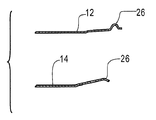
Figures 6A-6C illustrate the components of various embodiments of the connector during various manufacturing steps.
여기에서 기술된 본 발명의 태양은 커넥터에 가요성 비임의 제1 및 제2 어레이를 포함하는 것에 관한 것이다. 가요성 비임은 비임들 중 적어도 일부 사이에 있는 공동에 수용될 때, 정합 커넥터에 전기 접속을 제공한다. 각 가요성 비임의 말단부는 정합 커넥터와 전기 접촉하는 접촉 지점을 포함한다. 가요성 비임의 제1 및 제2 어레이는 서로 중첩될 수도 있다. 이러한 점에서, 전기 커넥터의 전체적인 크기는 감소될 수 있는 한편, 정합 커넥터와의 결합을 위한 접촉부 및/또는 접촉 영역의 개수를 증가시킨다.An aspect of the invention described herein relates to including a first and a second array of flexible beams in a connector. The flexible beam provides electrical connection to the mating connector when received in a cavity between at least some of the beams. The distal end of each flexible beam includes a point of contact in electrical contact with the mating connector. The first and second arrays of flexible beams may overlap each other. In this regard, the overall size of the electrical connector can be reduced while increasing the number of contacts and / or contact areas for engagement with the mating connector.
본 발명의 또 다른 태양에 따르면, 가요성 비임은 정합 커넥터와 접촉하는 다중 접촉 영역을 형성하도록 형상화되는 접촉 영역을 가질 수도 있다. 이러한 점에서, 접촉 지점의 전체 개수는 증가될 수도 있고, 이에 상응하여 커넥터의 전류 전달 용량도 또한 증가될 수도 있다.According to another aspect of the invention, the flexible beam may have a contact area that is shaped to form multiple contact areas in contact with the mating connector. In this regard, the total number of contact points may be increased, and correspondingly the current carrying capacity of the connector may also be increased.
본 발명의 또 다른 태양에 따르면, 커넥터는 커넥터가 비용 효율적으로 제조될 수 있도록 스탬핑 공정을 통해 제조될 수도 있다.According to another aspect of the present invention, the connector may be manufactured through a stamping process so that the connector can be manufactured cost-effectively.
또 다른 태양에 따르면, 가요성 비임의 제1 및 제2 어레이는 재료의 공통 시트로부터 랜싱 가공될 수도 있다. 이는 제1 및 제2 어레이의 가요성 비임들 사이에 있는 어떤 재료도 제거하지 않으면서 달성될 수 있는데, 이는 커넥터를 제조하는데 사용되는 재료의 양을 감소시켜서 생산 비용을 절감할 수도 있다.According to another aspect, the first and second arrays of flexible beams may be lanced from a common sheet of material. This may be accomplished without removing any material between the flexible beams of the first and second arrays, which may reduce the amount of material used to manufacture the connector, thereby reducing production costs.
또 다른 태양에 따르면, 가요성 비임의 제1 및 제2 어레이의 접촉 지점은 정합 커넥터가 수용되는 방향을 따라 서로 분리될 수도 있고, 이는 추가적 접촉부가 커넥터 내에 포함되게 할 수도 있다.According to another aspect, the points of contact of the first and second arrays of flexible beams may be separated from one another along the direction in which the mating connector is received, which may cause additional contacts to be included within the connector.
이제 도면으로 돌아가서, 일 실시예에 따라 전기 커넥터의 단면도를 도시하는 도 1를 먼저 참조한다. 커넥터는 하나 이상의 접촉 지점(18)을 각각 포함하는 가요성 비임(16)의 제1 어레이(12), 제2 어레이(14) 및 후드(10)를 포함한다. 후드와 함께, 가요성 비임 및 접촉 지점은 정합 커넥터(22)가 수용될 수도 있는 실질적으로 원통형인 공동(20)을 형성한다. 가요성 비임의 각 어레이는 일 단부에서는 기부(24)에 연결되고, 타 단부에서는 수용될 때 정합 커넥터와 전기 접속을 형성하도록 원통형 공동의 내부로 연장되는 하나 이상의 접촉 지점(18)을 갖는 접촉 영역(26)을 갖는다. 도 2에 도시된 또 다른 예시적인 실시예는 재료의 공통 부분으로부터 형성되고 공통 기부(24)를 갖는 가요성 비임의 제1 및 제2 어레이를 포함한다.Turning now to the drawings, reference is made first to Fig. 1, which shows a cross-sectional view of an electrical connector according to one embodiment. The connector includes a
본 발명의 실시예는 커넥터에 의해 점유되는 전체적인 외형부의 사이즈를 증가시킬 필요없이, 정합 커넥터와의 접촉 영역의 양을 증가시키는 다양한 특징부를 포함한다. 이러한 특징부는 제1 및 제2 어레이의 접촉부가 둘레에 놓이는 반경을 포함한다. 도 1 및 도 2에 도시된 가요성 비임은 접촉 영역이 놓여있는 것보다 큰 반경에 놓여있는 기부에 연결된다. 이러한 점에서, 접촉 영역에서의 각 가요성 비임들 사이의 임의의 갭(27)은 기부(24) 근처의 가요성 비임들 사이의 갭보다 작을 수 있다. 접촉 영역에서의 갭 사이즈의 이러한 감소는, 추가적 비임이 커넥터에 포함되게 할 수도 있고/있거나, 각 커넥터에서의 보다 큰 접촉 영역들을 허용하여서, 정합 커넥터와의 전체 접촉 영역을 증가시키고 커넥터와 관련된 전체적 전기적 저항을 감소시킬 수도 있다. 몇몇 실시예에서, 적어도 정합 커넥터가 공동에 존재하지 않을 때, 가요성 비임은 서로 접촉할 수 있어서, 가요성 비임들 사이의 어떠한 갭도 없앨 수 있다. 그러나 이는 본 발명의 태양이 이러한 점에 제한되지 않기 때문에, 모든 실시예가 접촉부들 사이의 갭 사이즈를 줄이도록 구성되는 가요성 비임을 포함하는 것은 아니라는 것이 이해될 것이다. 일례로써, 커넥터는 가요성 비임의 기부 및 어레이(들)가 정합 커넥터를 수용하기 위한 슬롯형 공동을 포함하는 실시예에서와 같이, 만곡 표면 주위로 연장되지 않도록 구성될 수도 있다.Embodiments of the present invention include various features that increase the amount of contact area with the mating connector without having to increase the size of the overall contour occupied by the connector. These features include a radius in which the contacts of the first and second arrays are placed around. The flexible beams shown in Figures 1 and 2 are connected to a base that lies in a larger radius than the contact area lies on. In this regard, any
가요성 비임의 어레이는 커넥터의 전체적인 크기를 증가시킬 필요없이, 정합 커넥터와 접촉할 수 있는 영역을 증가시키기 위해 서로 함께 중첩되거나 포개어질 수도 있다. 이러한 중첩된 커넥터의 일례가 도 1 및 도 2의 실시예에 도시된다. 도시된 바와 같이 포개지는 방식으로 비임을 구성하는 것은, "삽입 방향" - 정합 커넥터가 커넥터의 공동으로 삽입되는 방향을 따라 취해지는 커넥터의 전체 길이를 감소시키는 것을 도울 수도 있다. 중첩된 구성은 가요성 비임이 전체적인 커넥터 외형부를 증가시키지 않으면서 특정 커넥터에 바람직할 수 있는 바람직한 접촉력, 변위 범위, 및/또는 다른 특징부에 적합한 길이를 갖게 할 수도 있다. 도 1 및 도 2가 한 쌍의 포개진 가요성 어레이를 도시하고 있지만, 단일 배열 또는 2개보다 많은 어레이를 갖는 커넥터도 또한 가능하다는 것이 이해될 수 있다. 일례로써, 몇몇 실시예는 3개 어레이, 4개 어레이, 5개 어레이 또는 심지어 5개보다 많은 포개진 가요성 비임의 어레이를 가질 수도 있다.The array of flexible beams may overlap or overlap with each other to increase the area in contact with the mating connector, without having to increase the overall size of the connector. One example of such a nested connector is shown in the embodiment of Figs. Constructing the beam in a superimposed manner as shown may help reduce the overall length of the connector taken along the direction in which the "insertion direction" -matched connector is inserted into the cavity of the connector. The overlapping configuration may have desirable contact forces, displacement ranges, and / or lengths suitable for other features that may be desirable for a particular connector, without increasing the overall connector contour. Although Figures 1 and 2 illustrate a pair of overlapping flexible arrays, it is understood that a connector having a single array or more than two arrays is also possible. By way of example, some embodiments may have arrays of three arrays, four arrays, five arrays, or even more than five embedded beams.
여기에 사용된 바와 같이, "중첩된" 또는 "포개진"이라는 용어는 가요성 비임의 제2 어레이의 일부가 공동과 가요성 비임의 제1 어레이 사이에 적어도 부분적으로 위치 설정되는 것을 지칭한다. 개별 비임이 또 다른 어레이의 비임 또는 갭 위에 정확히 정렬되지 않더라도 "중첩된" 또는 "포개진" 것으로 고려된다. 커넥터 내의 다양한 어레이의 가요성 비임이 커넥터 내에서 삽입 방향으로 동일한 길이로 연장된다면 "중첩된" 또는 "포개진" 것으로 고려되지 않는다.As used herein, the term "nested" or "overlap" refers to that a portion of the second array of flexible beams is positioned at least partially between the cavity and the first array of flexible beams. Quot; overlap "or" overlap "even if the individual beams are not exactly aligned over the beam or gap of another array. Quot; overlap "or" juxtaposed "if the flexible beams of the various arrays in the connector extend the same length in the insertion direction within the connector.
도 1 및 도 2의 실시예에 도시된 바와 같이, 가요성 비임의 중첩된 어레이는 부가적으로 또는 대안으로, 커넥터의 삽입 길이가 감소되게 할 수도 있다. 여기에 사용된 바와 같이, 용어 "삽입 길이"는 초기 전기 접촉이 이루어진 후, 전기 커넥터와 정합 커넥터 사이의 완전한 전기 통로가 실현될 때까지, 정합 커넥터가 삽입 방향을 따라 이동되어야 하는 길이를 지칭한다. 도 1 및 도 2의 실시예에서, 삽입 길이는 삽입 방향에 따라 취해진 제1 어레이(12) 및 제2 어레이(14)의 접촉 지점들(18) 사이의 거리이다.As shown in the embodiment of Figs. 1 and 2, the overlapping array of flexible beams may additionally or alternatively also cause the insertion length of the connector to be reduced. As used herein, the term "insertion length " refers to the length through which the mating connector must be moved along the insertion direction until a complete electrical path between the electrical connector and the mating connector is realized after the initial electrical contact is made . In the embodiment of Figures 1 and 2, the insertion length is the distance between the contact points 18 of the
가요성 비임은 베릴륨 동 또는 다른 도전성 재료와 같은 탄성 재료로 제조될 수 있어서, 비임 자체의 가요성이 커넥터와 정합 커넥터의 접촉 지점 사이에 접촉력을 제공할 수도 있다. 이러한 점에서, 편향력을 제공하기 위한 추가적인 기계 요소가 전체적으로 커넥터로부터 생략될 수 있는데, 이는 커넥터 외형부 사이즈에 대한 높은 비율 접촉 영역을 유지하는 것을 도울 수 있다. 그러나 본 발명의 태양이 이러한 점에 제한되지 않기 때문에, 추가적인 기계 요소가 접촉력을 제공하도록 포함될 수도 있다.The flexible beam may be made of an elastic material such as beryllium copper or other conductive material so that the flexibility of the beam itself may provide a contact force between the connector and the point of contact of the mating connector. In this regard, additional mechanical elements for providing a biasing force may be omitted from the connector as a whole, which may help to maintain a high ratio of contact area to connector contour size. However, since aspects of the present invention are not limited in this respect, additional mechanical elements may be included to provide the contact force.
커넥터의 실시예는 정합 커넥터와의 우수한 전기 접속을 촉진하기 위해 다양한 특징부를 합체시킬 수도 있다. 이해되는 바와 같이, 커넥터의 접촉 지점과 정합 커넥터의 표면 사이의 와이핑(wiping) 정도는 연결 공정 동안에 바람직할 수도 있다. 이 와이핑 작업은 접촉 지점 및/또는 정합 커넥터에서 존재할 수도 있는 바람직하지 않은 산화, 불순물 및/또는 부스러기를 제거할 수도 있다. 그러나 너무 많은 와이핑은 정합 요소 및/또는 접촉 지점으로부터 코팅을 제거할 수도 있거나, 다르게는 커넥터의 일부를 파손시킬 수도 있고, 이에 따라 임의의 하나의 영역에서 발생하는 와이핑의 양을 제한하는 것이 바람직할 수도 있다.Embodiments of the connector may incorporate various features to facilitate good electrical connection with the mating connector. As will be appreciated, the degree of wiping between the point of contact of the connector and the surface of the mating connector may be desirable during the connection process. This wiping operation may remove undesirable oxidation, impurities and / or debris that may be present at the point of contact and / or the mating connector. However, too much wiping may remove the coating from the mating element and / or the point of contact, or otherwise break a portion of the connector, thereby limiting the amount of wiping that occurs in any one region Lt; / RTI >
몇몇 실시예에 따르면, 제1 어레이 및 제2 어레이와 관련된 접촉 지점은 제2 세트의 접촉부에 대해, 공동을 중심으로 회전될 수도 있다(즉, 도 3에 개략적으로 도시된 바와 같이, 삽입 방향과 평행하게 놓여 있는 축을 중심으로 회전될 수도 있다). 이러한 점에서, 각 접촉 지점은 과도한 와이핑이 임의의 하나의 주어진 스폿에서 발생하는 것을 방지하는 것을 돕기 위해, 삽입될 때 정합 커넥터의 다양한 영역을 와이핑할 수도 있다. 몇몇 실시예에 따르면, 제2 어레이의 가요성 비임은 도 3에 도시된 바와 같이 그리고 도 2에 도시된 실시예에서 본래 발생되는 것과 같이, 서로에 대해 제1 어레이의 갭 위에 정렬될 수도 있다. 본 발명의 태양이 이러한 점에 제한되지 않기 때문에, 모든 실시예가 서로에 대해 공동을 중심으로 회전되는 접촉 지점을 갖는 것은 아닐 수도 있다는 것이 이해될 수 있다. 또한, 다른 접근법이 접촉 지점과 정합 커넥터 사이의 와이핑의 양을 제어하도록 부가적으로 또는 대안적으로 사용될 수도 있다.According to some embodiments, the contact points associated with the first array and the second array may be rotated about the cavity, relative to the second set of contacts (i.e., as shown schematically in Figure 3, Or may be rotated about an axis lying parallel). In this regard, each contact point may wipe various areas of the mating connector when inserted, to help prevent excessive wiping from occurring at any one given spot. According to some embodiments, the flexible beams of the second array may be aligned over the gaps of the first array relative to one another, as shown in Fig. 3 and as they occur inherently in the embodiment shown in Fig. It is to be understood that not all aspects of the present invention may have a point of contact rotated about the cavity with respect to each other, since aspects of the present invention are not limited in this respect. In addition, other approaches may additionally or alternatively be used to control the amount of wiping between the point of contact and the mating connector.
공동을 향하는 접촉 영역의 표면(30)은 삽입 방향과 직교한 방향으로 서로 분리되는 다중 접촉 지점(18)을 제공하도록 형상화된다. 몇몇 실시예에 따르면, 표면(30)은 이 효과를 달성하는 것을 돕기 위해, 도 4에 도시된 바와 같이 오목한 곡률(32)을 갖도록 형상화될 수 있다. 도시된 바와 같은 곡률은, 접촉 영역이 공동을 향하는 표면의 측부분에 위치 설정되는 2개의 접촉 지점에서 정합 커넥터와 접촉하여야 하도록 정합 커넥터(22)의 곡률보다 크다. 이 방식으로 형성된 각 가요성 비임의 접촉 지점은 삽입 과정 동안에 실질적으로 동시에 정합 커넥터와 접촉하게 할 것이다. 각 가요성 비임에 2개의 접촉 지점을 제공하는 것은, 특히 접촉 지점의 곡률을 정합 커넥터의 곡률에 맞추는 것이 달성되기 어렵기 때문에, 둥근 표면을 갖는 정합 커넥터와의 전기 접속을 위한 큰 영역을 궁극적으로 제공할 수도 있다. 본 발명의 태양이 이러한 점에 제한되지 않기 때문에, 접촉 영역의 만곡 표면은 코인 가공(coining) 작업을 포함하는 다양한 접근법을 통해, 또는 다양한 다른 기술을 통해 형성될 수도 있다. 본 발명의 태양이 이러한 점에 제한되지 않기 때문에, 표면은 오목한 곡률과 다른 형상을 또한 포함할 수 있다.The
본 발명의 실시예는 정합 커넥터의 적절한 삽입을 촉진하기 위한 특징부를 포함할 수도 있다. 이러한 특징부는 도 1, 도 2 및 도 5에 도시된 바와 같이, 커넥터의 개구에 후드(34)를 포함한다. 후드는 공동 내로 삽입될 수도 있는 정합 커넥터의 최대 직경을 규정한 개구(36)를 갖는다. 이러한 점에서, 개구는 대형 정합 커넥터가 공동 내로 부주의하게 삽입되어 커넥터를 손상시킬 수 있는 것을 방지할 수도 있다.Embodiments of the present invention may include features for facilitating proper insertion of the mating connector. These features include a
후드 또는 커넥터의 다른 특징부는 스터빙(stubbing)을 방지하도록 가요성 비임과 결합할 수도 있다. 스터빙은 가요성 비임이 정합 커넥터의 삽입 시에, 공동으로부터 멀어지는 대신에 공동을 가로질러 이동하는 경우에 발생되고, 부적절한 연결 또는 손상을 가져올 수 있다. 도 1, 도 2 및 도 5의 후드 실시예는, 특정 지점을 넘어서 내향 이동되는 것을 방지하도록 제1 어레이의 가요성 비임과 결합하는 립(38)을 포함하고, 이 때문에 스터빙을 방지할 수 있다. 다른 특징부가 스터빙을 방지하기 위해 커넥터에 합체될 수도 있다는 것이 이해될 수 있다. 일례로써, 도 1과 도 2에 도시된 바와 같이, 제2 어레이의 가요성 비임은 공동으로부터 멀어지게 경사지는 말단부를 포함한다. 경사진 단부는 정합 커넥터와의 결합 시에, 비임이 외향 이동되는 것을 촉진하도록 돕고, 이는 스터빙을 방지하는 것을 도울 수 있다. 또한 도시되는 바와 같이, 제2 어레이에서 가요성 비임의 말단부는 커넥터의 후드를 통해 수용될 수도 있는 핀의 반경과 대략 동등하거나 더 큰 반경을 따라 놓여있다. 이 배열은 정합 커넥터가 가요성 비임의 극 말단부와 직접적으로 접촉하는 것을 방지할 수도 있어서, 이에 따라 스터빙을 방지할 수도 있다.Other features of the hood or connector may also be combined with the flexible beam to prevent stubbing. Stubbing occurs when the flexible beam is moved across the cavity instead of moving away from the cavity upon insertion of the mating connector and can lead to improper connection or damage. The hood embodiment of Figures 1, 2 and 5 includes a
접촉 영역의 형상은 정합 커넥터를 삽입하기 위해 필요한 최대 삽입력을 감소시키는 것을 도울 수도 있다. 도 5는 일 실시예에 따라, 둥근 정합 커넥터를 커넥터에 삽입하는 것과 관련된 힘을 개략적으로 도시한다. 도시된 바와 같이, 접촉부와 정합 커넥터의 배열은 삽입 방향을 따라 적용되는 삽입력(42)의 초기부(40)가 커넥터의 삽입 방향과 실질적으로 수직인 반경 방향으로, 외향으로 지향되게 한다. 이 외향 반경 방향 힘(40)은 외향으로 제1 어레이(또는 임의의 다른 어레이)의 가요성 비임을 누르는 것을 도울 수도 있다. 핀이 커넥터의 공동 내로 추가로 이동됨에 따라, 정합 커넥터와 접촉 지점 사이의 결합 지점(44)이 정합 커넥터의 둥근 표면 주위에서 이동될 수 있어서, 보다 적은 삽입력은 반경 방향 외향으로 지향되고 보다 큰 비율은 삽입 방향을 따라 지향된다.The shape of the contact area may help reduce the maximum insertion force required to insert the mating connector. Figure 5 schematically illustrates the force associated with inserting a rounded mating connector into a connector, in accordance with one embodiment. As shown, the arrangement of the contacts and the mating connector allows the
커넥터의 특징부는 접촉 지점의 일부 또는 모두에 의해 정합 커넥터에 적용되는 최소 접촉력을 제어하도록 구성될 수도 있다. 일 일례에서, 가요성 비임은 도 5에 도시된 바와 같이, 후드에 대해 예비 로딩(preloaded)될 수 있는데, 이는 일단 대응하는 가요성 비임이 후드로부터 멀리 이동된다면 예비 하중(preload)과 적어도 동등한 접촉력이 정합 커넥터에 적용되는 것을 보장하는 것을 돕는다. 몇몇 실시예에 따르면, 제1 어레이의 적어도 가요성 비임은 비임 상의 접촉 지점당 약 5그램의 힘으로 예비 로딩될 수도 있다. 즉, 단일의 접촉 지점을 갖는 비임에 있어서 예비 하중은 약 5그램일 수도 있고, 도 4에 도시된 바와 같이, 각 측면에 접촉 지점을 갖는 만곡 면을 갖는 비임에 있어서 예비 하중은 약 10그램일 수도 있다. 그러나, 더 크거나 더 작은 크기의 예비 하중도 또한 가능하다는 것을 이해할 수 있다. 예비 하중은 0.094 직경 핀(12 사이즈)과 정합하도록 구성되는 실시예에 있어서 접촉 지점당 약 3그램 내지 약 75그램 사이의 범위에 있는 것으로 일반적으로 예상될 수 있다. 다른 사이즈의 정합 커넥터를 위한 예비 하중은 이 범위 내에 있을 수도 있거나, 본 발명의 태양이 이러한 점에서 제한되지 않기 때문에 심지어 더 클 수도 있다.The feature of the connector may be configured to control the minimum contact force applied to the mating connector by some or all of the contact points. In one example, the flexible beam can be preloaded to the hood, as shown in Fig. 5, since once the corresponding flexible beam is moved away from the hood, at least a contact force equal to the preload Is applied to the mating connector. According to some embodiments, at least the flexible beam of the first array may be preloaded with a force of about 5 grams per contact point on the beam. That is, for a beam having a single point of contact, the preload may be about 5 grams, and for a beam having a curved surface with points of contact on each side, as shown in Figure 4, the preload is about 10 grams It is possible. However, it will be appreciated that a preload of greater or smaller size is also possible. The preload can generally be expected to range from about 3 grams to about 75 grams per contact point in embodiments configured to match 0.094 diameter pins (12 sizes). The preload for different sized mating connectors may be within this range, or even larger because the aspects of the present invention are not limited in this respect.
정합 커넥터를 삽입하도록 요구되는 최대 삽입력은 삽입 동안의 다양한 시간에 정합 커넥터와 접촉하게 하도록 배열되는 접촉 지점을 가짐으로써와 같이, 다양한 설계를 통하여 제어될 수도 있다. 이는 삽입 방향을 따라 가요성 비임의 제1 및 제2 어레이와 관련된 접촉부를 분리함으로써 도 1 및 도 2의 실시예에서 이루어진다. 이해되는 바와 같이, 정합 커넥터와 커넥터에서의 접촉 지점 사이의 초기 접촉은, 적어도 접촉 지점이 그의 이동 범위를 통하여 커넥터의 원통형 공동으로부터 멀리 외향으로 이동될 때까지, 더 큰 힘과 관련될 수도 있다. 도 1 및 도 2의 실시예에서, 정합 커넥터와 가요성 비임의 제2 어레이의 접촉 지점 사이에 접촉이 이루어지기 전에, 가요성 비임의 제1 어레이의 접촉 지점은 그의 이동 범위를 통하여 적어도 부분적으로 이동된다. 제2 어레이와 관련된 접촉 지점이 이후에 그의 이동 범위를 통하여 이동되기 때문에, 이들 접촉 지점을 외향으로 초기에 이동시키는 것과 관련된 보다 큰 힘은, 삽입 동안에, 제1 어레이의 접촉 지점을 이동시키는 것과 관련된 보다 큰 힘과 동시에 존재하지 않는다. 결과적으로, 전체 최대 삽입력은 감소될 수도 있다.The maximum insertion force required to insert a mating connector may be controlled through a variety of designs, such as by having a contact point arranged to contact the mating connector at various times during insertion. This is done in the embodiment of Figures 1 and 2 by separating the contacts associated with the first and second arrays of flexible beams along the insertion direction. As will be appreciated, the initial contact between the mating connector and the point of contact at the connector may be associated with a greater force, at least until the point of contact is moved outwardly away from the cylindrical cavity of the connector through its range of movement. In the embodiment of Figures 1 and 2, before contact is made between the mating connector and the contact point of the second array of flexible beams, the point of contact of the first array of flexible beams is at least partially . Since the contact points associated with the second array are subsequently moved through its travel range, the greater forces associated with initially moving these contact points outwardly are associated with moving the point of contact of the first array during insertion It does not exist at the same time with greater power. As a result, the total maximum insertion force may be reduced.
일 예시적인 실시예에 따르면, 제1 어레이(또는 임의의 다른 어레이)의 가요성 비임은 접촉 지점이 삽입 방향으로 서로에 대해 엇갈리게 되도록 구성된다. 이러한 실시예에서, 제1 어레이의 접촉 지점은 정합 커넥터를 삽입하기 위한 최대 삽입력을 추가로 감소시키도록 다양한 시간에 그의 이동 범위를 통해 이동된다.According to one exemplary embodiment, the flexible beams of the first array (or any other array) are configured such that the points of contact are staggered with respect to each other in the insertion direction. In this embodiment, the contact point of the first array is moved through its range of motion at various times to further reduce the maximum insertion force for insertion of the mating connector.
여기에서 논의된 바와 같이, 가요성 비임의 어레이가 커넥터에서 중첩되는 것은 커넥터의 삽입 길이를 감소시키는 것을 도울 수도 있다. 본 발명의 이 태양은 상기에 기술된 것과 유사한 실시예에서 특히 유용하게 판명될 수 있고, 여기서 공통 어레이의 접촉 지점은 삽입 방향으로 서로에 대해 엇갈리게 된다. 그러나, 본 발명의 태양이 이러한 점에 제한되지 않기 때문에, 도 1 및 도 2와 유사하게, 실시예는 원형부(28) 주위에 놓여 있도록 배열되는(즉, 엇갈리게 되지 않는) 대응하는 접촉 지점을 갖는 가요성 비임을 가질 수도 있다.As discussed herein, the overlap of the array of flexible beams in the connector may help to reduce the insertion length of the connector. This aspect of the invention may be particularly useful in embodiments similar to those described above, wherein the points of contact of the common array are staggered with respect to each other in the inserting direction. However, since the embodiment of the present invention is not limited in this respect, similar to Figs. 1 and 2, the embodiment may include a corresponding contact point that is arranged to lie around (i.e., not staggered) Or may have a flexible beam.
커넥터의 예시적인 실시예는 가요성 비임이 삽입 동안 정합 커넥터를 수용하기 위해 바람직한 접촉력과 적절한 이동 범위를 제공하도록 구성되게 한다. 비임 역학이 그의 이동 범위를 통하여 각 가요성 비임을 이동시키는 것과 관련된 힘의 양과, 이에 따른 정합 커넥터에 적용되는 접촉력을, 적어도 부분적으로 결정할 수도 있다는 것이 이해된다. 도 1 및 도 2에 도시된 바와 같이 가요성 비임을 중첩하는 것은, 바람직한 이동 범위를 통하여 바람직한 접촉력을 적용하도록 구성되기 위해 각 가요성 비임을 위한 커넥터 내에 공간을 제공할 수도 있다. 비임의 설계가 변경될 수도 있는 변수들 중 일부는 비임 길이, 반경 방향 또는 원주 방향으로의 비임 폭, 비임 단면 형상, 재료 등을 포함한다. 도 1 및 도 2에 도시된 실시예는, 접촉 지점이 편향되지 않은 위치로부터 약 0.2032mm(0.008") 또는 예비 로딩된 위치로부터 약 0.127mm(0.005')의 반경 방향 이동 범위를 통하여 이동된 후에, 정합 커넥터에 대하여, 접촉 지점당 약 5그램 내지 약 25그램을 제공하도록 일반적으로 구성된다. 그러나, 이는 다른 이동 범위 및 접촉력은 다른 실시예에서 바람직할 수도 있고 본 발명의 태양은 임의의 일 세트의 값으로 제한되지 않는다는 것을 이해할 수 있다.An exemplary embodiment of the connector allows the flexible beam to be configured to provide a suitable range of contact with the desired contact force to accommodate the mating connector during insertion. It is understood that the beam mechanics may at least partially determine the amount of force associated with moving each flexible beam through its range of movement and hence the contact force applied to the mating connector. Overlapping the flexible beams as shown in Figures 1 and 2 may provide space within the connector for each flexible beam to be configured to apply the desired contact force through the desired range of movement. Some of the variables upon which the design of the beam may change include beam length, radial or circumferential beam width, beam cross-sectional shape, material, and the like. The embodiment shown in Figures 1 and 2 is characterized in that the contact point is moved from a non-deflected position through a radial movement range of about 0.2032 mm (0.008 ") or preloaded position to about 0.127 mm (0.005 & , It is generally constructed to provide about 5 grams to about 25 grams per contact point for the mating connector, although this may be desirable in other embodiments with different travel ranges and contact forces, Quot; is < / RTI >
본 발명의 실시예는 비용 효율적인 방법으로 제조하는 것을 용이하게 할 수도 있다. 도 1의 실시예를 제조하기 위한 한가지 접근법은 아래 더 상세하게 기술되고 도 6a 내지 도 6c에서 대표적인 방법으로 설명된 바와 같이 도전성 재료의 시트로부터 커넥터의 스탬핑 구성요소를 포함한다.Embodiments of the present invention may facilitate manufacturing in a cost-effective manner. One approach to manufacturing the embodiment of FIG. 1 includes stamping components of a connector from a sheet of conductive material, as described in more detail below and illustrated in an exemplary manner in FIGS. 6A-6C.
처음에, 베릴륨 동과 유사한 도전성 재료의 편평한 시트는 도 6a에 도시된 바와 같이, 기부로부터 연장되는 가요성 비임을 형성하도록 블랭크 가공된다. 본 발명의 태양이 이 방법으로 제한되지 않기 때문에, 각각의 가요성 비임은 단일 다이와 함께 공통 시간에 블랭크 가공될 수도 있거나, 가요성 어레이의 일부는 다양한 시간에 점진적으로 블랭크 가공될 수도 있다. 블랭크 가공 후에, 각 가요성 비임의 면은 정합 커넥터와 접촉하게 될 다중 접촉 지점을 형성하도록 코인 가공될 수 있다. 가요성 비임은, 기부에 의해 점유되는 것 이외의 평면 내로 연장되는 접촉 영역을 형성하기 위해 그리고 특정 실시예에서 요구될 수 있는 바와 같이 가요성 비임을 형상화하기 위해 블랭크 가공 및/또는 코인 가공 이전 또는 이후에 만곡될 수도 있다. 제1 어레이 및 제2 어레이의 가요성 비임이 어떻게 도 6b에 도시되는지의 일례. 이 후, 재료의 시트는 가요성 비임과 실질적으로 평행하게 있는 축을 중심으로 원통 형상으로 만곡된다. 이 만곡 공정 동안, 접촉 영역은 여기에 기술된 바와 같이 접촉 영역 사이의 갭을 감소시킬 수도 있는 시트의 기부보다 더 작은 반경을 따라 놓이도록, 원통형 공동을 향해 내향으로 연장된다. 이 후, 가요성 비임의 제2 어레이를 포함하는 재료의 원통형 시트는 도 6c에 도시된 바와 같이, 비임의 제1 어레이를 포함하는 재료의 원통형 시트에 포개질 수도 있다. 이후, 포개진 가요성 비임의 어레이는 커넥터를 형성하도록 후드에 위치 설정될 수도 있다.Initially, a flat sheet of electrically conductive material similar to beryllium copper is blanked to form a flexible beam extending from the base, as shown in Fig. 6A. As aspects of the present invention are not limited to this method, each flexible beam may be blanked at a common time with a single die, or a portion of the flexible array may be progressively blanked at various times. After the blanking process, the face of each flexible beam may be coined to form multiple contact points to be in contact with the mating connector. The flexible beam may be used to form a contact area extending into a plane other than that occupied by the base and to form a flexible beam as required in a particular embodiment and / It may be curved afterwards. An example of how the flexible beams of the first and second arrays are shown in FIG. 6b. Thereafter, the sheet of material curves into a cylindrical shape about an axis substantially parallel to the flexible beam. During this bending process, the contact area extends inwardly toward the cylindrical cavity so as to lie along a smaller radius than the base of the sheet, which may reduce the gap between the contact areas as described herein. The cylindrical sheet of material comprising the second array of flexible beams may then be superimposed on the cylindrical sheet of material comprising the first array of beams, as shown in Figure 6C. The array of embedded cellular beams may then be positioned in the hood to form a connector.
본 발명의 태양이 이러한 점에 제한되지 않기 때문에, 도 1의 실시예를 제조하기 위한 상기 단계들은 단지 예시적이고 다른 접근법이 또한 취해질 수 있다는 것이 이해될 수 있다. 단계의 순서는 변경될 수도 있고/있거나, 단계는 생략될 수도 있고/있거나, 단계는 대안의 접근법으로 달성될 수도 있다. 전체 제조 공정은 자동화될 수도 있거나 수동으로 수행될 수도 있거나, 자동화된 작동과 수동 작동의 임의의 조합을 포함할 수도 있다. 비제한적 일례로써, 가요성 비임의 형상은 시트가 가요성 비임을 형성하도록 블랭크 가공되기 전에 재료 시트에 부여될 수 있다. 또 다른 변경예에 따르면, 커넥터는 금속의 2개의 개별 스트립으로부터 가요성 비임의 제1 및 제2 어레이를 연속적으로 스탬핑함으로써 형성될 수도 있다. 재료의 개별 스트립을 처리하는 기계는 가요성 비임의 제1 어레이가 가요성 비임의 제2 어레이에 인접하여 형성되도록 구성될 수도 있다. 일단 스탬핑되면, 제1 및 제2 어레이는 연속적인 형성 공정의 일부로서 어레이들을 서로에 대해 활주시킴으로써 함께 조립될 수도 있다. 유사하게, 후드는 연속적인 형성 공정의 일부로서 가요성 비임의 포개진 배열 위로 활주될 수도 있다. 다른 실시예에서, 제1 및 제2 어레이 각각은 재료의 공통 스트립의 다양한 부분들로부터 점진적으로 형성될 수도 있다.It is to be understood that the steps for manufacturing the embodiment of Figure 1 are merely exemplary and that other approaches may also be taken, since aspects of the present invention are not limited in this respect. The order of the steps may be changed and / or the steps may be omitted and / or the steps may be accomplished with an alternative approach. The entire manufacturing process may be automated or may be performed manually, or it may include any combination of automated and manual operation. As a non-limiting example, the shape of the flexible beam may be imparted to the sheet of material before the sheet is blanked to form a flexible beam. According to another variant, the connector may be formed by successively stamping the first and second arrays of flexible beams from two separate strips of metal. A machine for processing individual strips of material may be configured such that a first array of flexible beams is formed adjacent to a second array of flexible beams. Once stamped, the first and second arrays may be assembled together by sliding the arrays relative to each other as part of a continuous forming process. Similarly, the hood may be flipped over a collapsed array of flexible beams as part of a continuous forming process. In another embodiment, each of the first and second arrays may be progressively formed from various portions of the common strip of material.
도 2에 도시된 실시예는 가요성 비임의 제1 및 제2 어레이가 이들이 공동 기부를 공유하도록 재료 시트의 공통 부분으로부터 스탬핑될 수도 있는 것을 제외하고, 상기에 기술된 것과 유사한 절차를 통하여 이루어질 수도 있다. 이러한 점에서, 재료의 더 큰 시트 또는 재료의 제2 시트에 대한 필요성을 제거함으로써, 그리고 가요성 비임들 사이로부터 제거될 재료과 같은 폐기된 재료를 감소시킴으로써, 커넥터를 위한 재료 비용이 감소될 수 있다. 이 실시예에서, 랜싱 가공 공정은 재료의 공통 시트로부터 제1 및 제2 어레이의 가요성 비임을 분리하는데 사용될 수도 있다. 가요성 비임은 랜싱 가공 공정 후에 코인 가공될 수도 있고, 이후 형상은 랜싱 가공 공정 이전 또는 이후에 가요성 비임에 부여될 수도 있다.The embodiment shown in FIG. 2 may be accomplished through a similar procedure as described above, except that the first and second arrays of flexible beams may be stamped from a common portion of the sheet of material so that they share a common base have. In this regard, by eliminating the need for a larger sheet of material or a second sheet of material, and by reducing discarded material such as material to be removed from between the flexible beams, the material cost for the connector can be reduced . In this embodiment, the lancing process may be used to separate the flexible beams of the first and second arrays from a common sheet of material. The flexible beam may be coined after the lancing process, and then the shape may be imparted to the flexible beam before or after the lancing process.
또한, 다양한 공정이 후드를 형성하는데 사용될 수도 있다. 몇몇 접근법에 따르면, 후드는 스테인레스 강으로 형성되고, 딥 드로잉(deep drawing) 공정을 통하여 형상화된다. 여기에서, 후드는 기계적인 기능을 주로 수행할 수도 있다. 다른 실시예에서, 본 발명의 태양이 이러한 점에 제한되지 않기 때문에, 또한 후드는 커넥터의 가요성 어레이와 같이 스탬핑될 수도 있고, 더 도전성인 재료로 제조될 수도 있다.In addition, various processes may be used to form the hood. According to some approaches, the hood is formed of stainless steel and is shaped through a deep drawing process. Here, the hood may perform mainly mechanical functions. In other embodiments, since the aspects of the present invention are not limited in this respect, the hood may also be stamped like a flexible array of connectors and may be made of a more conductive material.
또한, 다양한 기술은 서로에 그리고/또는 후드에 커넥터의 포개진 어레이를 조립하는데 사용될 수도 있다. 한가지 접근법에 따르면, 포개진 커넥터의 제1 어레이는 우선 후드 내측에 위치 설정되고, 이후 제2 어레이는 제1 어레이 내측에 위치 설정된다. 이후, 후드 및 가요성 비임의 어레이 각각은 용접, 브레이징, 스테이킹(staking) 등과 같은 체결 공정을 통하여 함께 유지될 수도 있다. 스테이킹 공정에서, 후드 또는 어레이의 기부에서 재료의 일부는 재료의 일부가 정합 구성요소를 방해할 때까지 변형되고, 이에 따라 구성요소가 분리되는 것을 방지한다. 다른 실시예에서, 제1 및 제2 어레이는 우선 함께 조립될 수 있고, 이후 용접, 리벳팅, 가압 끼워 맞춤, 및/또는 스테이킹과 같은 다양한 체결 기술을 통하여 함께 유지될 수도 있다. 이후, 조립된 제1 및 제2 어레이는 후드에 위치 설정될 수도 있다. 유사한 체결 기술은 후드에 가요성 비임의 조립된 어레이를 유지하는데 사용될 수도 있다.In addition, various techniques may be used to assemble a collapsed array of connectors to each other and / or to the hood. According to one approach, the first array of juxtaposed connectors is first positioned inside the hood, and then the second array is positioned inside the first array. Each of the hood and flexible beam arrays may then be held together via a fastening process such as welding, brazing, staking, and the like. In the staking process, a portion of the material at the base of the hood or array is deformed until a portion of the material interferes with the matching component, thereby preventing the component from being detached. In other embodiments, the first and second arrays may first be assembled together and then held together via various fastening techniques such as welding, riveting, press fit, and / or staking. The assembled first and second arrays may then be positioned in the hood. Similar fastening techniques may be used to hold the assembled array of flexible beams in the hood.
후드의 실시예는 다른 접근법에 따라 정합 구성요소에서 끝날 수도 있다. 일 실시예에서, 동과 같은 재료의 도전성 플러그는 후드의 기부 내에 위치 설정될 수도 있다. 플러그는 커넥터를 제 위치에 유지시키기 위해 후드에 대해, 가압 끼움 방식으로 재료의 시트 또는 시트들의 기부를 압축할 수도 있다. 또 다른 실시예에서, 플러그는 정합 커넥터가 플러그를 통해 통과하게 하도록 형상이 원통형일 수도 있다.The embodiment of the hood may end in a matching component according to another approach. In one embodiment, the conductive plug of the same material may be positioned within the base of the hood. The plug may compress the base of the sheet or sheets of material in a press fit manner relative to the hood to keep the connector in place. In yet another embodiment, the plug may be cylindrical in shape to allow the mating connector to pass through the plug.
다른 변형예가 다양한 적용을 수용하기 위해 커넥터에 통합될 수 있다. 일례로써, 커넥터의 기부 부분 및 이에 따른 전체 길이는, 커넥터가 케이블과 같은 정합 구성요소에 기계적 지지를 제공하기 위한 것이라면 연장될 수도 있다. 이러한 길이는 보드 대 보드 타입 연결(board-to-board type connections)에서와 같이 보다 적은 기계적 지지가 필요할 수도 있는 경우에 감소될 수도 있다. 핫 플러그(hot plug)를 필요로 하는 적용예는 도전성이 있거나, 삽입 동안 정합 커넥터와 초기 전기 접촉을 하게 하는 도전성 재료를 합체한 후드를 포함할 수도 있다. 몇몇 실시예에서, 다른 구성이 또한 가능할지라도, 이 도전성 재료는 후드의 외측에 위치 설정될 수도 있고, 후드에서 개구의 내향으로 연장될 수도 있다.Other variations may be incorporated into the connector to accommodate various applications. By way of example, the base portion and thus the overall length of the connector may be extended if the connector is intended to provide mechanical support to a matching component, such as a cable. This length may be reduced if less mechanical support may be required, such as in board-to-board type connections. An application that requires a hot plug may be conductive or may include a hood incorporating a conductive material that causes initial electrical contact with the mating connector during insertion. In some embodiments, although other configurations are also possible, the conductive material may be positioned outside of the hood and extend inwardly of the opening in the hood.
본 발명의 실시예는 전력 또는 데이터를 전달하도록 구성될 수도 있다. 일례로써, 도 1 및 도 2에 도시된 각 실시예는 전력을 전달하도록 구성된다. 이러한 실시예에서, 각 접촉 지점은 기부와 같이, 커넥터에서 공통 지점으로의 전기 통로를 일반적으로 제공한다. 이어서, 기부는 전력을 정합 구성요소에 전달하기 위해 커넥터의 외측 지점에서 끝날 수도 있다. 커넥터 외형부의 사이즈에 대한 접촉 영역의 높은 비율은 커넥터가 비교적 작은 손실을 갖는 전력을 전달하게 할 수도 있어서, 전력 전달에 적합한 실시예를 이룰 수 있다.Embodiments of the present invention may be configured to transmit power or data. By way of example, each embodiment shown in Figures 1 and 2 is configured to transmit power. In this embodiment, each contact point generally provides an electrical path from the connector to a common point, such as a base. The base may then be terminated at an external point of the connector to deliver power to the matching component. A high ratio of the contact area to the size of the connector contour may cause the connector to deliver power with a relatively small loss, so that an embodiment suitable for power delivery can be achieved.
여기에서 논의된 바와 같은 도 1 및 도 2의 실시예는, 둥근 핀 형상 정합 커넥터를 수용하는 실질적으로 원통형인 공동을 포함한다. 그러나, 또한 커넥터가 다른 형상의 정합 커넥터를 수용하기 위한 공동을 형성하도록 구성될 수도 있다는 것을 이해될 수 있다. 일례로써, 실시예는 직사각형 또는 정사각형 정합 커넥터를 수용하기 위한 직사각형 또는 정사각형 공동, 카드 에지를 수용하기 위한 슬롯 형상의 공동, 또는 버스 바(bus bar)의 금속 블레이드를 형성하도록 배열되는 가요성 비임의 어레이를 포함할 수도 있다. 여기에 기술된 커넥터는 몇몇의 경우에 여기에 기술된 것과 같은 다중 커넥터를 포함하는 보다 큰 조립체의 부 구성요소일 수도 있다는 것이 이해될 수 있다.The embodiments of Figs. 1 and 2 as discussed herein include a substantially cylindrical cavity that accommodates a round pin-shaped mating connector. It is understood, however, that the connector may also be configured to form a cavity for receiving a different shaped mating connector. By way of example, embodiments may include a rectangular or square cavity for receiving a rectangular or square mating connector, a slot-shaped cavity for receiving a card edge, or a flexible beam arranged to form metal blades of a bus bar Array. ≪ / RTI > It is to be understood that the connector described herein may in some cases be a subcomponent of a larger assembly including multiple connectors as described herein.
따라서, 본 발명의 적어도 하나의 실시예의 여러 태양이 기술되었고, 다양한 변경, 변형 및 개선이 당해 기술분야의 숙련자들에게 용이하게 이루어질 것이라는 것이 이해될 수 있다. 이러한 변경, 변형 및 개선은 본 명세서의 일부이도록 의도되고, 본 발명의 기술사상과 범주 내에 포함되도록 의도된다. 따라서, 본원의 설명 및 도면은 단지 일례에 의한 것이다.Accordingly, it is to be understood that various aspects of at least one embodiment of the invention have been described and that various changes, modifications, and improvements will readily occur to those skilled in the art. Such variations, modifications, and improvements are intended to be a part of this disclosure, and are intended to be included within the spirit and scope of the present invention. Accordingly, the description and drawings of the present application are by way of example only.
본 발명은 추가 제한적인 것으로서 해석되어서는 안되는 이하 일례에 의해 추가로 설명된다.The invention is further illustrated by the following examples which should not be construed as further limiting.
일례An example
일례 1:Example 1:
도 1에 도시된 것으로 일반적으로 구성되는 일 일례는 베릴륨 동의 0.1778mm(0.007") 두께의 시트로부터 스탬핑되는 가요성 비임의 제1 어레이(23)와, 베릴륨 동의 0.1778mm(0.007") 두께의 시트로부터 스탬핑되는 가요성 비임의 제2 어레이(21)를 갖는다. 제1 및 제2 어레이의 각 가요성 비임은 0.254mm(0.010") 폭을 갖는다. 제1 어레이의 가요성 비임은 대응하는 접촉 지점이 2.1336mm(0.084") 직경 상에서 공동 주위에 놓여있도록, 도 5에 도시된 바와 같이 후드에 대해 예비 로딩된다. 제2 어레이의 가요성 비임은 대응하는 접촉 지점이 1.9304mm(0.076") 직경 상에서 공동 주위에 놓여있도록 형성된다. 제1 및 제2 어레이의 접촉 지점은 약 1.397mm(0.055")만큼 삽입 방향으로 서로 분리된다[즉, 커넥터는 1.397mm(0.055") 삽입 길이를 갖는다]. 가요성 비임의 제1 및 제2 어레이 각각은 0.186" 외경을 갖는 후드에 위치된다. 커넥터의 일 실시예의 이 일례는 2.3876mm(0.094") 직경(12 사이즈) 핀 형상 정합 커넥터를 수용하도록 구성된다.One example generally constructed as shown in FIG. 1 is a first array 23 of flexible beams stamped from a 0.007 " thick sheet of beryllium copper and a 0.007 " thick sheet of beryllium copper And a second array 21 of flexible beams stamped from the second array. Each flexible beam of the first and second arrays has a width of 0.010 ". The flexible beams of the first array are arranged such that the corresponding contact points lie around the cavity on a diameter of 0.084 " 5 for the hood as shown in FIG. The flexible beam of the second array is formed such that the corresponding contact points lie around the cavity on a diameter of 0.076 ". The contact points of the first and second arrays are oriented in the insertion direction by about 0.055 " (I.e., the connector has a 0.055 "insertion length). Each of the first and second arrays of flexible beams is located in a hood having an outer diameter of 0.186". One example of one embodiment of the connector is configured to accommodate a 0.094 " diameter (12 size) pin-shaped mating connector.
Claims (39)
기부로부터 연장되는 가요성 비임의 제1 어레이와,
기부로부터 연장되는 가요성 비임의 제2 어레이를 포함하고,
가요성 비임의 제1 어레이는, 정합 커넥터를 수용하도록 구성되는 공동 주위에 배열되고, 가요성 비임의 제1 어레이의 말단부는 공동 내에 수용될 때 정합 커넥터와의 전기 접속을 제공하는 제1 세트의 접촉 지점을 형성하도록 공동을 향해 내향 연장되고,
가요성 비임의 제2 어레이는 가요성 비임의 제1 어레이에 대해 포개지고, 가요성 비임의 제2 어레이의 말단부는 공동 내에 수용될 때 정합 커넥터와의 전기 접속을 제공하는 제2 세트의 접촉 지점을 형성하도록 공동을 향해 내향 연장되는
전기 커넥터.An electrical connector for mating with a mating connector,
A first array of flexible beams extending from the base,
And a second array of flexible beams extending from the base,
Wherein the first array of flexible beams is arranged around a cavity configured to receive a mating connector and wherein a distal end of the first array of flexible beams has a first set of Extending inwardly toward the cavity to form a contact point,
A second array of flexible beams is superimposed over the first array of flexible beams and a distal end of the second array of flexible beams is coupled to a second set of contact points Lt; RTI ID = 0.0 >
Electrical connector.
기부는 재료의 공통 시트이고,
가요성 비임의 제1 및 제2 어레이는 기부로부터 연장되는
전기 커넥터.The method according to claim 1,
The base is a common sheet of material,
The first and second arrays of flexible beams extend from the base
Electrical connector.
가요성 비임의 제1 및 제2 어레이는 재료의 공통 시트로부터 형성되는
전기 커넥터.3. The method of claim 2,
The first and second arrays of flexible beams are formed from a common sheet of material
Electrical connector.
제1 및 제2 어레이의 가요성 비임은 제1 및 제2 어레이의 비임들 사이로부터 재료를 제거하지 않으면서 재료의 공통 시트로부터 형성되는
전기 커넥터.The method of claim 3,
The flexible beams of the first and second arrays are formed from a common sheet of material without removing material from between the beams of the first and second arrays
Electrical connector.
제1 세트의 접촉 지점은 제2 세트의 접촉 지점에 대해 공동 주위에 엇갈리게 되어 있는
전기 커넥터.The method according to claim 1,
The first set of contact points being staggered about the cavity with respect to the second set of contact points
Electrical connector.
제1 세트의 접촉 지점은 공동 주위에 놓여있는 원형부를 따라 위치 설정되는
전기 커넥터.The method according to claim 1,
The first set of contact points are positioned along a circular portion lying about the cavity
Electrical connector.
제2 세트의 접촉 지점은 공동 주위에 놓여있는 원형부를 따라 위치 설정되는
전기 커넥터.The method according to claim 6,
The second set of contact points are positioned along a circular portion lying about the cavity
Electrical connector.
제1 및 제2 어레이의 각 가요성 비임은 단일 접촉 지점을 포함하는
전기 커넥터.The method according to claim 1,
Each flexible beam of the first and second arrays includes a single point of contact
Electrical connector.
제1 및 제2 어레이의 각 가요성 비임은 한 쌍의 접촉 지점을 갖는
전기 커넥터.The method according to claim 1,
Each flexible beam of the first and second arrays has a pair of contact points
Electrical connector.
제1 및 제2 어레이의 각 가요성 비임은 단면이 직사각형인
전기 커넥터.The method according to claim 1,
Each flexible beam of the first and second arrays has a rectangular cross section
Electrical connector.
가요성 비임의 제1 및 제2 어레이가 내부에 위치 설정되는 후드를 더 포함하고,
후드는 정합 커넥터가 관통하여 수용되는 원형 개구를 포함하는
전기 커넥터.The method according to claim 1,
Further comprising a hood in which the first and second arrays of flexible beams are positioned internally,
The hood includes a circular opening through which the mating connector is received
Electrical connector.
후드는 제1 어레이의 가요성 비임이 세트 포인트를 넘어서 공동 내로 내향 연장되는 것을 방지하도록 제1 어레이의 가요성 비임과 결합하는
전기 커넥터.12. The method of claim 11,
The hood is coupled to the flexible beam of the first array to prevent the flexible beam of the first array from extending inward beyond the set point into the cavity
Electrical connector.
제1 어레이의 가요성 비임은 후드에 대해 예비 로딩되는
전기 커넥터.12. The method of claim 11,
The flexible beam of the first array is preloaded to the hood
Electrical connector.
기부는 가요성 비임의 제1 어레이가 연장되는 제1 재료 시트와, 가요성 비임의 제2 어레이가 연장되는 제2 재료 시트를 포함하는
전기 커넥터.The method according to claim 1,
The base includes a first material sheet extending a first array of flexible beams and a second material sheet extending a second array of flexible beams
Electrical connector.
정합 커넥터와 조합되는
전기 커넥터.The method according to claim 1,
Be combined with the mating connector
Electrical connector.
기부로부터 연장되는 가요성 비임의 제1 어레이를 포함하고,
가요성 비임의 제1 어레이는, 정합 커넥터를 수용하도록 구성되는 원통형 공동 주위에 배열되고,
제1 어레이의 각 가요성 비임의 말단부는 공동을 향해 내향 연장되고, 공동 내에 수용될 때 정합 커넥터와의 전기 접속을 제공하도록 2개 이상의 접촉 지점을 형성하는 표면을 갖는 접촉 영역을 갖고,
2개 이상의 접촉 지점은 원통형 공동 주위를 회전하는 반경을 따라 서로 이격되는
전기 커넥터.An electrical connector for mating with a mating connector,
A first array of flexible beams extending from the base,
The first array of flexible beams is arranged around a cylindrical cavity configured to receive a mating connector,
The distal end of each flexible beam of the first array has a contact area extending inwardly towards the cavity and having a surface defining two or more contact points to provide electrical connection with the mating connector when received within the cavity,
The two or more contact points are spaced from one another along a radius of rotation about the cylindrical cavity
Electrical connector.
기부로부터 연장되는 가요성 비임의 제2 어레이를 더 포함하고,
가요성 비임의 제2 어레이는 가요성 비임의 제1 어레이의 내측에 포개지고,
제2 어레이의 각 가요성 비임의 말단부는 공동을 향해 내향 연장되고, 공동 내에 수용될 때 정합 커넥터와의 전기 접속을 제공하도록 2개 이상의 접촉 지점을 형성하는 표면을 갖는 접촉 영역을 갖고,
제2 어레이의 각 가요성 비임의 2개 이상의 접촉 지점은 원통형 공동 주위를 회전하는 반경을 따라 서로 이격되는
전기 커넥터.17. The method of claim 16,
And a second array of flexible beams extending from the base,
The second array of flexible beams is superimposed inside the first array of flexible beams,
The distal end of each flexible beam of the second array extending inwardly towards the cavity and having a contact area having a surface defining two or more contact points to provide electrical connection with the mating connector when received within the cavity,
The two or more contact points of each flexible beam of the second array are spaced apart from one another along a radius of rotation about the cylindrical cavity
Electrical connector.
기부는 재료의 공통 시트이고,
가요성 비임의 제1 및 제2 어레이는 기부로부터 연장되는
전기 커넥터.18. The method of claim 17,
The base is a common sheet of material,
The first and second arrays of flexible beams extend from the base
Electrical connector.
제1 및 제2 어레이의 가요성 비임은 제1 및 제2 어레이의 비임들 사이로부터 재료를 제거하지 않으면서 재료의 공통 시트로부터 형성되는
전기 커넥터.19. The method of claim 18,
The flexible beams of the first and second arrays are formed from a common sheet of material without removing material from between the beams of the first and second arrays
Electrical connector.
가요성 비임의 제1 어레이의 접촉 영역은 가요성 비임의 제2 어레이의 접촉 영역에 대해 공동 주위에 엇갈리게 되어 있는
전기 커넥터.18. The method of claim 17,
The contact area of the first array of flexible beams is staggered about the cavity with respect to the contact area of the second array of flexible beams
Electrical connector.
가요성 비임의 제1 어레이의 접촉 영역은 공동 주위에 놓여있는 원형부를 따라 위치 설정되는
전기 커넥터.18. The method of claim 17,
The contact area of the first array of flexible beams is positioned along a circular portion lying about the cavity
Electrical connector.
가요성 비임의 제1 및 제2 어레이가 내부에 위치 설정되는 후드를 더 포함하고,
후드는 정합 커넥터가 관통하여 수용되는 원형 개구를 포함하는
전기 커넥터.18. The method of claim 17,
Further comprising a hood in which the first and second arrays of flexible beams are positioned internally,
The hood includes a circular opening through which the mating connector is received
Electrical connector.
후드는 제1 어레이의 가요성 비임이 세트 포인트를 넘어서 공동 내로 내향 연장되는 것을 방지하도록 제1 어레이의 가요성 비임과 결합하는
전기 커넥터.23. The method of claim 22,
The hood is coupled to the flexible beam of the first array to prevent the flexible beam of the first array from extending inward beyond the set point into the cavity
Electrical connector.
제1 어레이의 가요성 비임은 후드에 대해 예비 로딩되는
전기 커넥터.23. The method of claim 22,
The flexible beam of the first array is preloaded to the hood
Electrical connector.
정합 커넥터와 조합되는
전기 커넥터.17. The method of claim 16,
Be combined with the mating connector
Electrical connector.
도전성 재료 시트를 제공하는 단계와,
가요성 비임의 제1 어레이를 가요성 비임의 제2 어레이로부터의 분리시키도록 시트의 일부를 랜싱 가공하는 단계로서, 가요성 비임의 제1 및 제2 어레이는 시트의 기부 부분을 통해 서로 연결되어 유지되는, 시트의 일부를 랜싱 가공하는 단계와,
제1 세트의 접촉 영역을 형성하기 위해 가요성 비임의 제1 어레이의 말단부를 만곡시키는 단계와,
제2 세트의 접촉 영역을 형성하기 위해 가요성 비임의 제2 어레이의 말단부를 만곡시키는 단계와,
정합 커넥터를 수용하도록 구성되는 원통형 공동을 형성하기 위해 기부와 가요성 비임의 제1 및 제2 어레이를 만곡시키는 단계를 포함하는
전기 커넥터를 형성하는 방법.A method of forming an electrical connector,
Providing a conductive material sheet,
Lancing a portion of the sheet to separate a first array of flexible beams from a second array of flexible beams, wherein the first and second arrays of flexible beams are connected to each other through a base portion of the sheet Lancing a portion of the sheet to be held,
Bending the distal end of the first array of flexible beams to form a first set of contact areas,
Bending the distal end of the second array of flexible beams to form a second set of contact areas,
And bending the base and the first and second arrays of flexible beams to form a cylindrical cavity configured to receive the mating connector
A method of forming an electrical connector.
가요성 비임의 제1 어레이의 말단부를 만곡시키는 단계 및 가요성 비임의 제2 어레이의 말단부를 만곡시키는 단계는 랜싱 가공 단계 이전에 발생되는
전기 커넥터를 형성하는 방법.27. The method of claim 26,
Bending the distal end of the first array of flexible beams and bending the distal end of the second array of flexible beams may occur prior to the lancing step
A method of forming an electrical connector.
제1 어레이의 각 가요성 비임과 관련된 한 쌍의 접촉 지점을 형성하도록 가요성 비임의 제1 어레이의 말단부를 코인 가공하는 단계를 더 포함하는
전기 커넥터를 형성하는 방법.27. The method of claim 26,
Further comprising coin processing a distal end of the first array of flexible beams to form a pair of contact points associated with each flexible beam of the first array
A method of forming an electrical connector.
제2 어레이의 각 가요성 비임과 관련된 한 쌍의 접촉 지점을 형성하도록 가요성 비임의 제2 어레이의 말단부를 코인 가공하는 단계를 더 포함하는
전기 커넥터를 형성하는 방법.29. The method of claim 28,
Further comprising coin processing a distal end of the second array of flexible beams to form a pair of contact points associated with each flexible beam of the second array
A method of forming an electrical connector.
가요성 비임의 제1 어레이의 말단부를 만곡시키는 단계는 원통형 공동 주위에 원형으로 놓여있을 제1 세트의 접촉 영역을 형성하도록 말단부를 만곡시키는 단계를 포함하는
전기 커넥터를 형성하는 방법.27. The method of claim 26,
The step of bending the distal end of the first array of flexible beams includes bending the distal end to form a first set of contact areas that will lie in a circle around the cylindrical cavity
A method of forming an electrical connector.
가요성 비임의 제2 어레이의 말단부를 만곡시키는 단계는 원통형 공동 주위에 원형으로 놓여있을 제2 세트의 접촉 영역을 형성하도록 말단부를 만곡시키는 단계를 포함하는
전기 커넥터를 형성하는 방법.31. The method of claim 30,
The step of bending the distal end of the second array of flexible beams includes bending the distal end to form a second set of contact areas that will lie in a circle around the cylindrical cavity
A method of forming an electrical connector.
기부와 제1 및 제2 어레이의 가요성 비임을 후드에 장착하는 단계를 더 포함하는
전기 커넥터를 형성하는 방법.27. The method of claim 26,
Mounting the base and the flexible beams of the first and second arrays to the hood
A method of forming an electrical connector.
후드에 대해 가요성 비임의 제1 어레이를 예비 로딩하는 단계를 더 포함하는
전기 커넥터를 형성하는 방법.33. The method of claim 32,
Further comprising preloading the first array of flexible beams with respect to the hood
A method of forming an electrical connector.
도전성 재료의 제1 및 제2 시트부를 제공하는 단계와,
연장되는 가요성 비임의 제1 어레이 및 제1 기부 부분을 형성하기 위해 제1 시트부를 블랭크 가공하는 단계와,
연장되는 가요성 비임의 제2 어레이 및 제2 기부 부분을 형성하기 위해 제2 시트부를 블랭크 가공하는 단계와,
제1 세트의 접촉 영역을 형성하기 위해 가요성 비임의 제1 어레이의 말단부를 만곡시키는 단계와,
제2 세트의 접촉 영역을 형성하기 위해 가요성 비임의 제2 어레이의 말단부를 만곡시키는 단계와,
정합 커넥터를 수용하도록 구성되는 원통형 공동을 형성하기 위해 가요성 비임의 제1 및 제2 어레이를 만곡시키는 단계와,
가요성 비임의 제2 어레이를 가요성 비임의 제1 어레이에 포개는 단계를 포함하는
전기 커넥터를 형성하는 방법.A method of forming an electrical connector,
Providing first and second sheet portions of conductive material;
Blanking the first sheet portion to form a first array and a first base portion of the elongate flexible beam,
Blanking the second sheet portion to form a second array and a second base portion of the elongate flexible beam,
Bending the distal end of the first array of flexible beams to form a first set of contact areas,
Bending the distal end of the second array of flexible beams to form a second set of contact areas,
Bending the first and second arrays of flexible beams to form a cylindrical cavity configured to receive the mating connector,
Superimposing a second array of flexible beams over a first array of flexible beams
A method of forming an electrical connector.
원통형 공동을 형성하기 위해 가요성 비임의 제1 및 제2 어레이를 만곡시키는 단계는 가요성 비임의 제2 어레이를 가요성 비임의 제1 어레이에 포개는 단계 이전에 발생되는
전기 커넥터를 형성하는 방법.35. The method of claim 34,
Curving the first and second arrays of flexible beams to form a cylindrical cavity may occur prior to the step of superimposing the second array of flexible beams on the first array of flexible beams
A method of forming an electrical connector.
제1 어레이의 각 가요성 비임 상에 복수의 접촉 지점을 형성하기 위해 가요성 비임의 제1 어레이의 말단부를 코인 가공하는 단계를 더 포함하는
전기 커넥터를 형성하는 방법.35. The method of claim 34,
Further comprising coin processing a distal end of the first array of flexible beams to form a plurality of contact points on each flexible beam of the first array
A method of forming an electrical connector.
제2 어레이의 각 가요성 비임 상에 복수의 접촉 지점을 형성하기 위해 가요성 비임의 제2 어레이의 말단부를 코인 가공하는 단계를 더 포함하는
전기 커넥터를 형성하는 방법.35. The method of claim 34,
Further comprising coin processing the distal end of the second array of flexible beams to form a plurality of contact points on each flexible beam of the second array
A method of forming an electrical connector.
가요성 비임의 제1 및 제2 어레이를 후드에 장착하는 단계를 더 포함하는
전기 커넥터를 형성하는 방법.35. The method of claim 34,
And mounting the first and second arrays of flexible beams to the hood
A method of forming an electrical connector.
가요성 비임의 제1 어레이를 후드에 대해 예비 로딩하는 단계를 더 포함하는
전기 커넥터를 형성하는 방법.39. The method of claim 38,
Further comprising preloading the first array of flexible beams with respect to the hood
A method of forming an electrical connector.
Applications Claiming Priority (2)
| Application Number | Priority Date | Filing Date | Title |
|---|---|---|---|
| US12/025,734 | 2008-02-04 | ||
| US12/025,734 US7806737B2 (en) | 2008-02-04 | 2008-02-04 | Stamped beam connector |
Publications (2)
| Publication Number | Publication Date |
|---|---|
| KR20110013349A KR20110013349A (en) | 2011-02-09 |
| KR101578568B1 true KR101578568B1 (en) | 2015-12-17 |
Family
ID=40366870
Family Applications (1)
| Application Number | Title | Priority Date | Filing Date |
|---|---|---|---|
| KR1020107019641A Expired - Fee Related KR101578568B1 (en) | 2008-02-04 | 2009-01-26 | Stamped beam connector |
Country Status (5)
| Country | Link |
|---|---|
| US (1) | US7806737B2 (en) |
| EP (1) | EP2248227B1 (en) |
| JP (1) | JP5469094B2 (en) |
| KR (1) | KR101578568B1 (en) |
| WO (1) | WO2009099789A1 (en) |
Families Citing this family (38)
| Publication number | Priority date | Publication date | Assignee | Title |
|---|---|---|---|---|
| US20080293308A1 (en) * | 2007-05-24 | 2008-11-27 | Tribotek, Inc. | Pivoting wafer connector |
| US7806699B2 (en) * | 2008-01-31 | 2010-10-05 | Methode Electornics, Inc. | Wound coil compression connector |
| US7794235B2 (en) | 2008-01-31 | 2010-09-14 | Methode Electronics, Inc. | Continuous wireform connector |
| US7806737B2 (en) | 2008-02-04 | 2010-10-05 | Methode Electronics, Inc. | Stamped beam connector |
| FR2960103B1 (en) * | 2010-05-11 | 2013-05-31 | Souriau | CONNECTOR ASSEMBLY FOR LIVE CONNECTION |
| FR2970605B1 (en) | 2011-01-14 | 2013-02-08 | Radiall Sa | SLEEVE FOR ELECTRICAL CONNECTOR AND METHOD FOR ASSEMBLING SAME. |
| DE102011110567B4 (en) * | 2011-08-13 | 2023-05-25 | Kostal Kontakt Systeme Gmbh | Laminated contact element for an electrical connector part |
| DE102011111581B4 (en) * | 2011-08-20 | 2023-06-07 | Volkswagen Aktiengesellschaft | Method for producing an electrical plug-in contact connection, connector device and connector pair |
| US8414339B1 (en) * | 2011-10-31 | 2013-04-09 | Lear Corporation | Electrical terminal and receptacle assembly |
| JP2013114911A (en) * | 2011-11-29 | 2013-06-10 | Auto Network Gijutsu Kenkyusho:Kk | Socket terminal |
| DE102012201124B4 (en) * | 2012-01-26 | 2020-03-26 | Lisa Dräxlmaier GmbH | Contact element |
| JP5649010B2 (en) * | 2012-03-12 | 2015-01-07 | 古河電気工業株式会社 | Contact spring for connector terminals |
| DE202012008961U1 (en) * | 2012-09-17 | 2012-10-12 | Rosenberger Hochfrequenztechnik Gmbh & Co. Kg | contact element |
| US9379468B2 (en) * | 2012-10-26 | 2016-06-28 | Cisco Technology, Inc. | Apparatus and method for allowing alignment mismatch in electrical connections |
| KR101967506B1 (en) * | 2013-01-15 | 2019-04-09 | 앱티브 테크놀러지스 리미티드 | Female electrical terminal |
| JP6086244B2 (en) * | 2013-11-19 | 2017-03-01 | 住友電装株式会社 | Multi-contact terminal |
| DE102014221671A1 (en) * | 2014-10-24 | 2016-04-28 | Zf Friedrichshafen Ag | Plug contact element |
| WO2016069570A2 (en) * | 2014-10-27 | 2016-05-06 | Fci Asia Pte. Ltd | Circular power connectors |
| US11504517B2 (en) | 2015-12-11 | 2022-11-22 | Nxstage Medical, Inc. | Fluid line connector devices methods and systems |
| DE102016112434A1 (en) * | 2016-07-06 | 2018-01-11 | Leukert Gmbh | High performance electrical contact |
| KR102514524B1 (en) * | 2016-11-17 | 2023-03-29 | 몰렉스 엘엘씨 | Floating socket connector |
| CN109256637B (en) * | 2017-07-13 | 2024-07-05 | 泰科电子(上海)有限公司 | Socket connector and method for plugging and unplugging plug connector |
| USD878304S1 (en) | 2018-06-29 | 2020-03-17 | Molex, Llc | Contact for a connector |
| KR102608751B1 (en) * | 2017-12-18 | 2023-12-04 | 타이코에이엠피 주식회사 | Connector assembly and manufacturing method of socket for connector assembly |
| CN108110470B (en) * | 2018-01-26 | 2024-05-24 | 深圳市特拉利线簧端子技术有限公司 | Metal reed structure, terminal structure and electric connector |
| USD877702S1 (en) | 2018-06-29 | 2020-03-10 | Molex, Llc | Socket connector |
| USD867298S1 (en) | 2018-06-29 | 2019-11-19 | Molex, Llc | Socket connector |
| USD868000S1 (en) | 2018-06-30 | 2019-11-26 | Molex, Llc | Socket connector |
| USD868001S1 (en) * | 2018-06-30 | 2019-11-26 | Molex, Llc | Socket connector |
| USD868002S1 (en) | 2018-07-06 | 2019-11-26 | Molex, Llc | Socket connector |
| USD867299S1 (en) | 2018-07-06 | 2019-11-19 | Molex, Llc | Socket connector |
| CN112054316B (en) * | 2019-06-06 | 2022-03-22 | 北京北方华创微电子装备有限公司 | Elastic equipotential ring, upper electrode gear box and assembly and semiconductor processing equipment |
| GB2585669B (en) * | 2019-07-10 | 2023-07-05 | Hypertac Sa | Female contact with stamped beams and method of manufacture |
| EP4027769A4 (en) | 2019-10-15 | 2023-10-18 | Briggs & Stratton, LLC | Electric vehicle with multiple ports |
| JP7292190B2 (en) * | 2019-11-29 | 2023-06-16 | ホシデン株式会社 | Ground terminal and connector with same |
| US10978832B1 (en) * | 2020-02-07 | 2021-04-13 | TE Connectivity Services Gmbh | Protection member to protect resilient arms of a contact assembly from stubbing |
| WO2023284857A1 (en) * | 2021-07-15 | 2023-01-19 | 长春捷翼汽车零部件有限公司 | Terminal having stamping elastic sheet structure |
| US12525755B2 (en) | 2021-07-19 | 2026-01-13 | Fci Usa Llc | Power connector for compact electronic systems |
Citations (3)
| Publication number | Priority date | Publication date | Assignee | Title |
|---|---|---|---|---|
| US5730628A (en) | 1996-09-25 | 1998-03-24 | Pacesetter, Inc. | Multi-contact connector for an implantable medical device |
| US6062919A (en) | 1997-08-29 | 2000-05-16 | Thomas & Betts International, Inc. | Electrical connector assembly having high current-carrying capability and low insertion force |
| US20030003784A1 (en) | 2001-07-02 | 2003-01-02 | Neidich Douglas A. | Interposer assembly. |
Family Cites Families (60)
| Publication number | Priority date | Publication date | Assignee | Title |
|---|---|---|---|---|
| BE465535A (en) * | ||||
| FR19359E (en) | 1915-01-20 | Eugene Troquet | Process and device for the sterilization and preservation of all food, pharmaceutical, surgical, etc. products. | |
| US2394020A (en) | 1943-09-03 | 1946-02-05 | Standard Telephones Cables Ltd | Connecting device and method of making the same |
| US3530422A (en) * | 1968-03-25 | 1970-09-22 | Elco Corp | Connector and method for attaching same to printed circuit board |
| US3665370A (en) * | 1971-02-08 | 1972-05-23 | Amp Inc | Zero-insertion force connector |
| US3927926A (en) | 1974-06-26 | 1975-12-23 | Ibm | Spiral braid connector |
| US4810213A (en) * | 1975-01-30 | 1989-03-07 | Square D Company | Low resistance electrical connecting assembly |
| NL173804C (en) * | 1977-06-30 | 1984-03-01 | Du Pont | Contact device for a chain plate. |
| JPS5848620Y2 (en) * | 1978-12-07 | 1983-11-07 | 三菱電機株式会社 | test terminal |
| US4462657A (en) * | 1980-04-18 | 1984-07-31 | Eaton Corporation | Compliant electrical connector for flat conductors |
| US4927369A (en) * | 1989-02-22 | 1990-05-22 | Amp Incorporated | Electrical connector for high density usage |
| DE8914951U1 (en) * | 1989-12-18 | 1991-04-18 | Grote & Hartmann Gmbh & Co Kg, 5600 Wuppertal | Electrical contact element with an overspring |
| US5030109A (en) * | 1990-08-24 | 1991-07-09 | Amp Incorporated | Area array connector for substrates |
| US5088942A (en) | 1990-09-07 | 1992-02-18 | Itt Corporation | Closed entry socket contact assembly |
| US5092781A (en) * | 1990-11-08 | 1992-03-03 | Amp Incorporated | Electrical connector using shape memory alloy coil springs |
| US5061191A (en) * | 1990-12-21 | 1991-10-29 | Amp Incorporated | Canted coil spring interposing connector |
| US5634801A (en) * | 1991-01-09 | 1997-06-03 | Johnstech International Corporation | Electrical interconnect contact system |
| US5154626A (en) | 1992-01-02 | 1992-10-13 | Watson Troy M | Double-helix zero insertion force connector system |
| US5232372A (en) * | 1992-05-11 | 1993-08-03 | Amp Incorporated | Land grid array connector and method of manufacture |
| US5273438A (en) * | 1992-08-19 | 1993-12-28 | The Whitaker Corporation | Canted coil spring array and method for producing the same |
| US5297968A (en) * | 1993-01-12 | 1994-03-29 | The Whitaker Corporation | Pluggable connector systems for flexible etched circuits |
| US5667413A (en) * | 1995-11-13 | 1997-09-16 | Alcoa Fujikura Ltd. | Socket-type electrical connector |
| JP2860536B2 (en) | 1996-06-24 | 1999-02-24 | 日本航空電子工業株式会社 | Coil spring contact multi-core connector |
| US5913687A (en) * | 1997-05-06 | 1999-06-22 | Gryphics, Inc. | Replacement chip module |
| DE19730484C1 (en) * | 1997-07-16 | 1998-10-22 | Siemens Ag | Circuit boards zero insertion force connector arrangement |
| CA2272458C (en) * | 1998-06-25 | 2008-03-18 | Leslie Laszlo Kerek | Hoodless electrical socket connector |
| US6102746A (en) * | 1999-04-30 | 2000-08-15 | Hypertronics Corporation | Coaxial electrical connector with resilient conductive wires |
| US6313523B1 (en) * | 1999-10-28 | 2001-11-06 | Hewlett-Packard Company | IC die power connection using canted coil spring |
| EP1107378B1 (en) * | 1999-11-30 | 2003-06-18 | Preci-Dip Durtal SA | Contact member for an electrical connector |
| EP1254494B1 (en) * | 2000-02-11 | 2003-10-01 | Tyco Electronics Belgium EC N.V. | Printed circuit board and connector assembly |
| JP3977009B2 (en) * | 2000-03-24 | 2007-09-19 | 株式会社ヨコオ | Coil spring contact type connector |
| FR2809238B1 (en) * | 2000-05-22 | 2003-11-28 | Frb Connectron | FEMALE ELEMENT OF ELECTRICAL CONNECTOR |
| GB0023290D0 (en) * | 2000-09-22 | 2000-11-08 | Smiths Industries Plc | Electrical contacts and methods of manufacture |
| US6439894B1 (en) * | 2001-01-31 | 2002-08-27 | High Connection Density, Inc. | Contact assembly for land grid array interposer or electrical connector |
| US7077573B2 (en) * | 2001-06-11 | 2006-07-18 | Tribotek, Inc. | Contact bearing |
| US6447317B1 (en) * | 2001-07-11 | 2002-09-10 | Hon Hai Precision Ind. Co., Ltd. | Backplane connector |
| US6945790B2 (en) * | 2002-01-15 | 2005-09-20 | Tribotek, Inc. | Multiple-contact cable connector assemblies |
| US20040214454A1 (en) * | 2002-01-15 | 2004-10-28 | Tribotek, Inc. | Method and apparatus for manufacturing woven connectors |
| US6951465B2 (en) * | 2002-01-15 | 2005-10-04 | Tribotek, Inc. | Multiple-contact woven power connectors |
| US7083427B2 (en) | 2002-01-15 | 2006-08-01 | Tribotek, Inc. | Woven multiple-contact connectors |
| JP4422482B2 (en) * | 2002-01-15 | 2010-02-24 | メソード・エレクトロニクス・インコーポレーテッド | Woven multi-contact connector |
| US7077662B2 (en) * | 2002-01-15 | 2006-07-18 | Tribotek, Inc. | Contact woven connectors |
| US7056139B2 (en) * | 2002-01-15 | 2006-06-06 | Tribotek, Inc. | Electrical connector |
| US6963684B2 (en) * | 2002-03-15 | 2005-11-08 | Jds Uniphase Corporation | Multi-band arrayed waveguide grating with improved insertion loss and wavelength accuracy |
| DE60312848T2 (en) * | 2002-05-17 | 2007-09-06 | Mitsubishi Cable Industries, Ltd. | CONNECTION CONNECTION |
| TW551630U (en) * | 2002-06-28 | 2003-09-01 | Hon Hai Prec Ind Co Ltd | Contact |
| US7029288B2 (en) | 2003-03-24 | 2006-04-18 | Che-Yu Li | Electrical contact and connector and method of manufacture |
| US7070419B2 (en) * | 2003-06-11 | 2006-07-04 | Neoconix Inc. | Land grid array connector including heterogeneous contact elements |
| JP2007529089A (en) * | 2003-07-11 | 2007-10-18 | トライボテック,インコーポレイテッド | Multi-contact woven electrical switch |
| US7097495B2 (en) * | 2003-07-14 | 2006-08-29 | Tribotek, Inc. | System and methods for connecting electrical components |
| US6958616B1 (en) * | 2003-11-07 | 2005-10-25 | Xilinx, Inc. | Hybrid interface apparatus for testing integrated circuits having both low-speed and high-speed input/output pins |
| GB0420666D0 (en) * | 2004-09-17 | 2004-10-20 | Smiths Group Plc | Electrical connectors |
| US7140916B2 (en) * | 2005-03-15 | 2006-11-28 | Tribotek, Inc. | Electrical connector having one or more electrical contact points |
| JP4634238B2 (en) * | 2005-06-29 | 2011-02-16 | 株式会社オートネットワーク技術研究所 | Female terminal bracket |
| US7214106B2 (en) * | 2005-07-18 | 2007-05-08 | Tribotek, Inc. | Electrical connector |
| US20080293308A1 (en) | 2007-05-24 | 2008-11-27 | Tribotek, Inc. | Pivoting wafer connector |
| US7806699B2 (en) * | 2008-01-31 | 2010-10-05 | Methode Electornics, Inc. | Wound coil compression connector |
| US7547215B1 (en) * | 2008-01-31 | 2009-06-16 | Methode Electronics, Inc. | Round connector with spring helix |
| US7794235B2 (en) * | 2008-01-31 | 2010-09-14 | Methode Electronics, Inc. | Continuous wireform connector |
| US7806737B2 (en) | 2008-02-04 | 2010-10-05 | Methode Electronics, Inc. | Stamped beam connector |
-
2008
- 2008-02-04 US US12/025,734 patent/US7806737B2/en active Active
-
2009
- 2009-01-26 EP EP09709401.5A patent/EP2248227B1/en active Active
- 2009-01-26 JP JP2010545072A patent/JP5469094B2/en active Active
- 2009-01-26 KR KR1020107019641A patent/KR101578568B1/en not_active Expired - Fee Related
- 2009-01-26 WO PCT/US2009/032036 patent/WO2009099789A1/en not_active Ceased
Patent Citations (3)
| Publication number | Priority date | Publication date | Assignee | Title |
|---|---|---|---|---|
| US5730628A (en) | 1996-09-25 | 1998-03-24 | Pacesetter, Inc. | Multi-contact connector for an implantable medical device |
| US6062919A (en) | 1997-08-29 | 2000-05-16 | Thomas & Betts International, Inc. | Electrical connector assembly having high current-carrying capability and low insertion force |
| US20030003784A1 (en) | 2001-07-02 | 2003-01-02 | Neidich Douglas A. | Interposer assembly. |
Also Published As
| Publication number | Publication date |
|---|---|
| US7806737B2 (en) | 2010-10-05 |
| JP5469094B2 (en) | 2014-04-09 |
| WO2009099789A1 (en) | 2009-08-13 |
| JP2011511418A (en) | 2011-04-07 |
| US20090197482A1 (en) | 2009-08-06 |
| EP2248227A1 (en) | 2010-11-10 |
| EP2248227B1 (en) | 2014-07-16 |
| KR20110013349A (en) | 2011-02-09 |
Similar Documents
| Publication | Publication Date | Title |
|---|---|---|
| KR101578568B1 (en) | Stamped beam connector | |
| US6997750B2 (en) | Electrical connector contact | |
| US9466907B2 (en) | Connector | |
| EP2652841B1 (en) | Receptacle terminal | |
| US9601854B2 (en) | Female terminal | |
| US20190312372A1 (en) | Connector and pin receiving contact for such a connector | |
| US20090311898A1 (en) | Hermaphroditic electrical contact | |
| CN118235300A (en) | Connector, connector assembly, and tool and method for assembling connector assembly | |
| JP6845438B2 (en) | How to manufacture connector terminals, connectors with connector terminals, and connector terminals | |
| EP3254338B1 (en) | Electrical contact | |
| KR20200020945A (en) | Coaxial connector with coaxial connector and coaxial cable | |
| US10038293B2 (en) | Method of making electrical contact with contact area geometry enlargement | |
| US8657616B2 (en) | Electrical contact normal force increase | |
| US11381009B2 (en) | Contact and connector | |
| CN115275660A (en) | Shielded electrical terminal with knurling on inner contact wall | |
| CN120453759A (en) | terminal |
Legal Events
| Date | Code | Title | Description |
|---|---|---|---|
| PA0105 | International application |
St.27 status event code: A-0-1-A10-A15-nap-PA0105 |
|
| T11-X000 | Administrative time limit extension requested |
St.27 status event code: U-3-3-T10-T11-oth-X000 |
|
| T11-X000 | Administrative time limit extension requested |
St.27 status event code: U-3-3-T10-T11-oth-X000 |
|
| T11-X000 | Administrative time limit extension requested |
St.27 status event code: U-3-3-T10-T11-oth-X000 |
|
| P11-X000 | Amendment of application requested |
St.27 status event code: A-2-2-P10-P11-nap-X000 |
|
| P13-X000 | Application amended |
St.27 status event code: A-2-2-P10-P13-nap-X000 |
|
| PG1501 | Laying open of application |
St.27 status event code: A-1-1-Q10-Q12-nap-PG1501 |
|
| A201 | Request for examination | ||
| P11-X000 | Amendment of application requested |
St.27 status event code: A-2-2-P10-P11-nap-X000 |
|
| P13-X000 | Application amended |
St.27 status event code: A-2-2-P10-P13-nap-X000 |
|
| PA0201 | Request for examination |
St.27 status event code: A-1-2-D10-D11-exm-PA0201 |
|
| D13-X000 | Search requested |
St.27 status event code: A-1-2-D10-D13-srh-X000 |
|
| D14-X000 | Search report completed |
St.27 status event code: A-1-2-D10-D14-srh-X000 |
|
| E902 | Notification of reason for refusal | ||
| PE0902 | Notice of grounds for rejection |
St.27 status event code: A-1-2-D10-D21-exm-PE0902 |
|
| T11-X000 | Administrative time limit extension requested |
St.27 status event code: U-3-3-T10-T11-oth-X000 |
|
| T11-X000 | Administrative time limit extension requested |
St.27 status event code: U-3-3-T10-T11-oth-X000 |
|
| P11-X000 | Amendment of application requested |
St.27 status event code: A-2-2-P10-P11-nap-X000 |
|
| P13-X000 | Application amended |
St.27 status event code: A-2-2-P10-P13-nap-X000 |
|
| T12-X000 | Administrative time limit extension not granted |
St.27 status event code: U-3-3-T10-T12-oth-X000 |
|
| E701 | Decision to grant or registration of patent right | ||
| PE0701 | Decision of registration |
St.27 status event code: A-1-2-D10-D22-exm-PE0701 |
|
| GRNT | Written decision to grant | ||
| PR0701 | Registration of establishment |
St.27 status event code: A-2-4-F10-F11-exm-PR0701 |
|
| PR1002 | Payment of registration fee |
St.27 status event code: A-2-2-U10-U12-oth-PR1002 Fee payment year number: 1 |
|
| PG1601 | Publication of registration |
St.27 status event code: A-4-4-Q10-Q13-nap-PG1601 |
|
| LAPS | Lapse due to unpaid annual fee | ||
| PC1903 | Unpaid annual fee |
St.27 status event code: A-4-4-U10-U13-oth-PC1903 Not in force date: 20181212 Payment event data comment text: Termination Category : DEFAULT_OF_REGISTRATION_FEE |
|
| PC1903 | Unpaid annual fee |
St.27 status event code: N-4-6-H10-H13-oth-PC1903 Ip right cessation event data comment text: Termination Category : DEFAULT_OF_REGISTRATION_FEE Not in force date: 20181212 |