KR101530096B1 - Method and system for recognizing state of uplink in wireless local area network using visible light communication - Google Patents
Method and system for recognizing state of uplink in wireless local area network using visible light communication Download PDFInfo
- Publication number
- KR101530096B1 KR101530096B1 KR1020090038343A KR20090038343A KR101530096B1 KR 101530096 B1 KR101530096 B1 KR 101530096B1 KR 1020090038343 A KR1020090038343 A KR 1020090038343A KR 20090038343 A KR20090038343 A KR 20090038343A KR 101530096 B1 KR101530096 B1 KR 101530096B1
- Authority
- KR
- South Korea
- Prior art keywords
- mobile node
- uplink
- signal
- minislot
- visible light
- Prior art date
- Legal status (The legal status is an assumption and is not a legal conclusion. Google has not performed a legal analysis and makes no representation as to the accuracy of the status listed.)
- Expired - Fee Related
Links
Images


Classifications
-
- H—ELECTRICITY
- H04—ELECTRIC COMMUNICATION TECHNIQUE
- H04W—WIRELESS COMMUNICATION NETWORKS
- H04W24/00—Supervisory, monitoring or testing arrangements
- H04W24/04—Arrangements for maintaining operational condition
-
- H—ELECTRICITY
- H04—ELECTRIC COMMUNICATION TECHNIQUE
- H04W—WIRELESS COMMUNICATION NETWORKS
- H04W24/00—Supervisory, monitoring or testing arrangements
- H04W24/02—Arrangements for optimising operational condition
-
- H—ELECTRICITY
- H04—ELECTRIC COMMUNICATION TECHNIQUE
- H04W—WIRELESS COMMUNICATION NETWORKS
- H04W72/00—Local resource management
- H04W72/04—Wireless resource allocation
- H04W72/044—Wireless resource allocation based on the type of the allocated resource
- H04W72/0446—Resources in time domain, e.g. slots or frames
-
- H—ELECTRICITY
- H04—ELECTRIC COMMUNICATION TECHNIQUE
- H04B—TRANSMISSION
- H04B10/00—Transmission systems employing electromagnetic waves other than radio-waves, e.g. infrared, visible or ultraviolet light, or employing corpuscular radiation, e.g. quantum communication
- H04B10/11—Arrangements specific to free-space transmission, i.e. transmission through air or vacuum
- H04B10/114—Indoor or close-range type systems
- H04B10/116—Visible light communication
Landscapes
- Engineering & Computer Science (AREA)
- Computer Networks & Wireless Communication (AREA)
- Signal Processing (AREA)
- Mobile Radio Communication Systems (AREA)
- Optical Communication System (AREA)
Abstract
본 발명은 가시광 무선 랜에서 상향 링크 상태를 인식하기 위한 방법에 있어서, 엑세스 포인트(Access Point)가 모바일 노드(Mobile Node)로부터 초기 접속을 위한 신호를 수신하는 과정과, 초기 접속을 위한 신호를 전송한 모바일 노드에게 가시광 무선 랜 통신에 사용되는 프레임의 경쟁 슬롯(Contention slot)을 구성하는 미니 슬롯(mini slot)중 하나를 할당하고, 모바일 노드에게 상향 링크 상태 파악을 위한 신호를 할당된 미니 슬롯을 통해 미리 설정된 주기로 반복 전송하도록 제어하는 과정과, 모바일 노드로부터 할당한 미니 슬롯을 통해 수신된 신호가 존재하는지 판단하는 과정과, 할당한 미니 슬롯을 통해 전송된 신호가 미리 설정된 주기로 미리 설정된 시간 이상 수신되면, 모바일 노드의 상향 링크의 설정이 완료된 것으로 판단하는 과정을 포함한다. There is provided a method for recognizing an uplink state in a visible light wireless LAN, the method comprising the steps of: receiving from an access point a signal for initial connection from a mobile node; One of the minislots constituting a contention slot of a frame used for visible light WLAN communication is allocated to a mobile node and a minislot allocated with a signal for ascertaining the uplink status is allocated to the mobile node Determining whether there is a signal received through a minislot allocated from a mobile node; and transmitting a signal transmitted through the allocated minislot at a predetermined cycle for a predetermined period of time or longer , It is determined that the uplink setting of the mobile node is completed.
가시광 통신, 엑세스 포인트(access point), 경쟁 슬롯(contention slot), 미니 슬롯 Visible light communication, an access point, a contention slot, a minislot
Description
본 발명은 가시광 통신(Visible Light Communication)에 관한 것으로서, 특히 가시광 통신을 이용한 무선(Wireless) 랜(LAN: Local Area Network) 시스템에서 상향 링크 상태를 인식하기 위한 방법 및 그 시스템에 관한 것이다.BACKGROUND OF THE
최근 LED(Light Emitting Diode)의 발광 효율이 개선되고 가격이 떨어짐에 따라 휴대기기, 디스플레이, 자동차, 신호등, 광고판 등의 특수 조명 시장뿐만 아니라 형광등 백열등과 같은 일반 조명 시장에서도 LED가 보편화 되어가고 있다. 특히 백색 LED의 발광 효율은 이미 백열등을 추월하였으며 형광등보다도 우수한 제품들이 출현하고 있다. 또한 최근에는 RF(Radio Frequency)대역 주파수 고갈, 여러 무선 통신 기술 간의 혼선, 통신의 보안 요구 증대, 4G 무선 기술의 초고속 유비쿼터스 통신 환경 도래 등으로 인하여 RF 기술과 상호 보완적인 가시광 무선 통신 기술에 대한 관심이 증가하고 있어 가시광 LED를 이용한 가시광 무선 통신에 대한 연구가 여러 기업 및 연구소 등에서 진행되고 있다.In recent years, LEDs have become commonplace in general lighting markets such as fluorescent lighting incandescent lamps as well as special lighting markets such as mobile devices, displays, automobiles, traffic lights, and billboards, as the luminous efficiency of LEDs (light emitting diodes) Particularly, the efficiency of white LED has exceeded that of incandescent lamps, and products superior to fluorescent lamps are emerging. Recently, interest in visible light wireless communication technology complemented with RF technology due to depletion of radio frequency (RF) band frequency, confusion among various wireless communication technologies, increase of security requirement of communication, and the arrival of ultra high speed ubiquitous communication environment of 4G wireless technology And research on visible light wireless communication using visible light LEDs is being conducted by various companies and research institutes.
현재 형광등이나 백열등을 사용하고 있는 가정이나 사무실 및 공공장소의 조명등은 향후 성능이 좋고 수명이 긴 LED로 대체될 것이다. 조명등으로 사용되는 LED에 인가하는 전류를 변조하면 조명 LED를 통신용 광원으로 활용할 수 있다. 즉, 추가적인 광원 없이 조명 LED만으로 방송 및 데이터 전송이 가능해 진다. LED 조명이 있는 곳에서 단말이나 노트북을 사용하는 사용자는 가시광 무선 송수신 모듈을 이용하여 무선 랜 형태의 데이터 통신을 할 수 있다. LEDs in homes, offices and public places that currently use fluorescent or incandescent lamps will be replaced by LEDs with good performance and long life span. If the current applied to the LED used as the illumination lamp is modulated, the illumination LED can be utilized as a communication light source. In other words, broadcasting and data transmission is possible only with the illumination LED without additional light source. A user who uses a terminal or a notebook in a place with LED light can perform wireless LAN type data communication using a visible light wireless transmission / reception module.
가시광 무선 통신과 다른 무선 RF 통신들과의 가장 큰 차이점은 데이터의 송수신 과정을 사용자가 확인할 수 있다는 점이다. 즉, 가시광 송수신 모듈의 위치를 사용자가 시각적으로 쉽게 파악할 수 있으며, 통신 경로 또한 확인할 수 있다. 이러한 특성을 이용하면 사용자가 직접 눈으로 가시광 송수신 모듈의 위치를 확인하면서 송신측과 수신측 사이의 통신 경로를 설정할 수 있다. The biggest difference between visible wireless communication and other wireless RF communications is that the user can check the transmission and reception of data. That is, the position of the visible light transmission / reception module can be easily visually recognized by the user, and the communication path can also be confirmed. With this characteristic, the user can directly set the communication path between the transmitting side and the receiving side while confirming the position of the visible light transmitting / receiving module with eyes.
종래의 RF 시스템은 데이터 전송에 무지향성 안테나를 사용한다. 따라서 신호를 송출하는 방향이 존재하지 않으며 그로 인해 전송한 신호가 주위의 모든 모바일 노드에게 전달된다. 그러나 무선 가시광 통신의 전송 장치는 직진하는 빛의 특성상 방향성이 존재하므로 특정 방향의 수신기로만 신호 즉, 데이터가 전송되는 특징을 가진다. RF 시스템에서 모바일 노드(Mobile Node)가 엑세스 포인트(Access Point)로 전송한 신호가 성공적으로 엑세스포인트에 도착하지 않게 되면, 모바일 노드는 자신이 엑세스포인트의 서비스 영역 밖에 존재하거나 채널 환경이 순간적으로 나빠진 것으로 판단하여 에러에 더욱 강한 변복조 방식을 사용하여 데이터를 전송하거나 에러가 발생한 데이터를 재전송하는 방식으로 대처한다. 그러나 무선 가 시광 시스템에서는 이와 같은 에러 상황 이외에 모바일 노드의 신호가 발생되는 상향 링크 방향이 엑세스포인트를 향하지 않고 다른곳을 향하게 틀어지거나 전송링크 상에 장애물이 있을 경우 데이터를 포함한 신호가 전달되지 못하는 상황이 발생할 수 있다. 따라서 종래의 RF 시스템과 같은 방식으로는 전송 실패에 효율적으로 대처할 수 없는 문제점이 있다.Conventional RF systems use omnidirectional antennas for data transmission. Therefore, there is no direction to transmit the signal, and the transmitted signal is transmitted to all surrounding mobile nodes. However, since the transmission apparatus of wireless visible light communication has a directionality due to the characteristic of light traveling straight ahead, it has a characteristic that a signal, that is, data is transmitted only to a receiver in a specific direction. In the RF system, when a signal transmitted from a mobile node to an access point does not successfully arrive at the access point, the mobile node determines whether the mobile node exists outside the service area of the access point or the channel environment is instantaneously deteriorated And the data is transmitted using a modulation / demodulation scheme that is more resistant to errors or a method of retransmitting data in which an error occurs. However, in the wireless optical network system, if the direction of the uplink in which the signal of the mobile node is generated does not face the access point other than the error state, or if there is an obstacle on the transmission link, Can occur. Therefore, there is a problem that transmission failure can not be efficiently coped with in the same manner as in the conventional RF system.
무선 가시광 통신 시스템에서는 주기적으로 전송되는 채널 상태 피드백 메시지를 이용하여 상향 링크의 상태를 판별하는데 사용할 수 있다. 그러나, 이러한 방식도 아래와 같은 두 가지 문제점이 발생할 수 있다. The wireless visible light communication system can use the channel status feedback message periodically transmitted to determine the state of the uplink. However, there are two problems as follows.
첫째, 무선 가시광 통신 시스템에서는 모바일 노드의 초기 접속 시 가시성을 제공하여 사용자에게 도움을 주기 위해서는 인증되지 않는 초기 접속 모바일 노드의 상향 링크 상태를 정확히 파악하여야 한다. 그러나 종래의 채널 상태를 측정한 메시지는 모바일 노드가 엑세스 포인트에 인증이 된 이후 전송되는 메시지로서 현재 인증되지 않은 모바일 노드의 경우에는 채널 상태 정보를 전달할 수 없으므로 이를 이용한 상향 링크의 상태 파악이 불가능하다. First, in the wireless visible light communication system, the uplink state of the initial access mobile node which is not authenticated must be accurately grasped in order to provide visibility to the user in the initial access of the mobile node. However, since the message measuring the conventional channel status is a message transmitted after the mobile node is authenticated to the access point, it can not transmit the channel status information in case of a mobile node that is not currently authenticated, .
둘째, 무선 가시광 통신 시스템에서 동작하는 모바일 노드의 데이터 채널은 모바일 노드의 이동성이 낮아 변화가 작으므로 주기적인 채널 상태 피드백 메시지보다는 채널 상황이 변할 때만 채널 정보를 전송하는 방안이 더 효율적이다. 즉 상향 링크 채널 상태 판별을 위해 모바일 노드가 주기적으로 채널 상태를 피드백하는 것은 불필요하게 데이터 슬롯의 자원을 소모하는 문제점이 있다. Second, the data channel of the mobile node operating in the wireless visible light communication system is less efficient because the mobility of the mobile node is low, so it is more effective to transmit the channel information only when the channel status changes rather than the periodical channel status feedback message. That is, the mobile node periodically feeds back the channel state to determine the uplink channel state, which consumes resources of the data slot unnecessarily.
본 발명은 가시광 통신을 이용한 무선랜 시스템에서 모바일 노드의 상향 링크 상태를 빠르고 정확하게 인식하며, 모바일 노드의 상태에 따라 적절한 메시지를 전송하여 정확하게 모바일 노드의 상향 링크를 연결하게 하며, 불필요한 데이터 슬롯의 자원 소모를 없애기 위한 방법 및 그러한 가시광 통신 무선랜 시스템을 제공하고자 한다. The present invention quickly and accurately recognizes the uplink state of a mobile node in a wireless LAN system using visible light communication, transmits an appropriate message according to the state of the mobile node, accurately connects the uplink of the mobile node, And to provide such a visible light communication wireless LAN system.
이를 달성하기 위한 본 발명의 일 형태에 따르면, 가시광 무선 랜에서 상향 링크 상태를 인식하기 위한 방법에 있어서, 엑세스 포인트(Access Point)가 모바일 노드(Mobile Node)로부터 초기 접속을 위한 신호를 수신하는 과정과, 상기 초기 접속을 위한 신호를 전송한 모바일 노드에게 상기 가시광 무선 랜 통신에 사용되는 프레임의 경쟁 슬롯(Contention slot)을 구성하는 미니 슬롯(mini slot)중 하나를 할당하고, 상기 모바일 노드에게 상향 링크 상태 파악을 위한 신호를 상기 할당된 미니 슬롯을 통해 미리 설정된 주기로 반복 전송하도록 제어하는 과정과, 상기 모바일 노드로부터 상기 할당한 미니 슬롯을 통해 수신된 신호가 존재하는지 판단하는 과정과, 상기 할당한 미니 슬롯을 통해 전송된 신호가 상기 미리 설정된 주기로 미리 설정된 시간 이상 수신되면, 상기 모바일 노드의 상향 링크의 설정이 완료된 것으로 판단하는 과정을 포함함을 특징으로 한다.According to an aspect of the present invention, there is provided a method for recognizing an uplink state in a visible light wireless LAN, the method comprising the steps of: receiving from an access point a signal for initial connection from a mobile node; And allocating one of the mini slots constituting a contention slot of a frame used for the visible light WLAN communication to the mobile node that has transmitted the signal for the initial connection, Determining whether a signal received through the assigned minislot is present from the mobile node, and transmitting the allocated signal to the mobile terminal, When a signal transmitted through the minislot is received over a predetermined period of time at the predetermined period, It characterized in that it comprises the step of determining to complete the setting of the uplink of the mobile node.
본 발명의 다른 형태에 따르면, 가시광 무선 랜에서 상향 링크 상태를 인식 하기 위한 시스템에 있어서, 위치 이동이 가능하며, 엑세스 포인트의 통신 범위 내에서 가시광 통신을 이용하여 엑세스 포인트(Access Point)와 통신을 수행하는 모바일 노드(Mobile node)와, 일정한 통신 범위를 가지며 상기 통신 범위 내에서 상기 모바일 노드와 가시광 통신을 이용하여 통신을 수행하며, 상기 모바일 노드로부터 초기 접속을 위한 신호를 수신한 경우, 상기 초기 접속을 위한 신호를 전송한 모바일 노드에게 상기 가시광 무선 랜 통신에 사용되는 프레임의 경쟁 슬롯(Contention slot)을 구성하는 미니 슬롯(mini slot)중 하나를 할당하고, 상기 모바일 노드에게 상향 링크 상태 파악을 위한 신호를 상기 할당된 미니 슬롯을 통해 미리 설정된 주기로 반복 전송하도록 제어하며, 상기 모바일 노드로부터 상기 할당한 미니 슬롯을 통해 전송된 신호가 존재하는지 판단하며, 상기 할당한 미니 슬롯을 통해 전송된 신호가 상기 미리 설정된 주기로 미리 설정된 시간 이상 수신되면, 상기 모바일 노드의 상향 링크의 설정이 완료된 것으로 판단하는 엑세스 포인트를 포함함을 특징으로 한다. According to another aspect of the present invention, there is provided a system for recognizing an uplink state in a visible light wireless LAN, the system being capable of moving a position, communicating with an access point using visible light communication within a communication range of an access point, The mobile node includes a mobile node having a predetermined communication range and performing communication using visible light communication with the mobile node within the communication range. When receiving a signal for initial connection from the mobile node, Allocates one of minislots constituting a contention slot of a frame used for the visible light WLAN communication to a mobile node that has transmitted a signal for connection, And to repeatedly transmit the signal for a predetermined period through the allocated minislot, Determining whether there is a signal transmitted through the allocated minislot from the mobile node, and if a signal transmitted through the allocated minislot is received for a predetermined time or more at the predetermined period, And the access point is determined to be completed.
본 발명은 가시광 통신을 이용한 무선랜 시스템에서 엑세스 포인트가 모바일 노드의 상향 링크 상태를 정확하게 파악할 수 있도록 한다. 또한 엑세스 포인트와 연결(association)되지 않은 모바일 노드에게도 초기 접속 후에 바로 미니 슬롯을 할당 하기 때문에 그 미니 슬롯을 통해 상향 링크의 상태를 인식할 수 있어 엑세스 포인트와 연결되지 않은 모바일 노드에 대해서도 통신 링크의 상태를 파악할 수 있다. The present invention enables an access point to accurately grasp the uplink state of a mobile node in a wireless LAN system using visible light communication. In addition, since a minislot is immediately allocated to a mobile node that is not associated with an access point after initial connection, the status of the uplink can be recognized through the minislot, so that even for a mobile node not connected to the access point, The state can be grasped.
또한 통신 링크의 상태를 파악하여 통신 채널 상황이 나쁜 경우에만 채널 상태 측정 메시지(CQI, Channel quality index)를 전송하기 때문에 기존에 주기적으로 채널 상태 측정 메시지를 전송하던 방식에 비해 불필요하게 소모되는 자원을 줄일 수 있으며, 또한 상향 링크 설정 실패시 모바일 노드가 그러한 사실을 사용자에게 표시하도록 하며, 가시광 신호를 발광하여 상향 링크의 가시성을 제공하도록하여 사용자에게 상향 링크 설정을 용이하게 할 수 있는 효과가 있다. In addition, since the channel quality measurement message (CQI) is transmitted only when the communication channel condition is bad by grasping the state of the communication link, compared to the method of periodically transmitting the channel state measurement message, unnecessary resources In addition, when the uplink setting is failed, the mobile node displays the fact to the user, and the visible light signal is emitted to provide the uplink visibility, so that the uplink setting can be facilitated to the user.
이하 첨부된 도면을 참조하여 본 발명을 구성하는 장치 및 동작 방법을 본 발명의 실시 예를 참조하여 상세히 설명한다. 하기 설명에서는 구체적인 구성 소자 등과 같은 특정 사항들이 나타나고 있는데 이는 본 발명의 보다 전반적인 이해를 돕기 위해서 제공된 것일 뿐 이러한 특정 사항들이 본 발명의 범위 내에서 소정의 변형이나 혹은 변경이 이루어질 수 있음은 이 기술분야에서 통상의 지식을 가진 자에게는 자명하다 할 것이다. 또한, 본 발명을 설명함에 있어서 본 발명과 관련된 공지 기술에 대한 구체적인 설명이 본 발명의 요지를 불필요하게 흐릴 수 있다고 판단되는 경우에 그 상세한 설명을 생략하기로 한다.DETAILED DESCRIPTION OF THE PREFERRED EMBODIMENTS Hereinafter, an apparatus and an operation method of the present invention will be described in detail with reference to the accompanying drawings. It will be appreciated that those skilled in the art will readily observe that certain changes in form and detail may be made therein without departing from the spirit and scope of the present invention as defined by the appended claims. To those of ordinary skill in the art. In the following description, well-known functions or constructions are not described in detail since they would obscure the invention in unnecessary detail.
본 발명은 가시광 무선랜 시스템에서 엑세스 포인트가 모바일 노드의 상태를 쉽게 인식할 수 있으며, 기존의 채널 상태 측정을 위한 불필요한 자원의 낭비를 최소화할 수 있는 방법을 제안한다. 이를 위해 본 발명은 가시광 무선 랜 통신의 초기 접속을 위해 사용되던 가시광 통신 프레임의 경쟁 슬롯(contention slot)을 이용한다. 본 발명은 경쟁 슬롯을 구성하는 미니 슬롯(mini slot)중 하나를 사용 자(모바일 노드)에게 전용으로 할당하며, 할당한 미니 슬롯을 통해 약속된 주기로 신호가 수신되는지 여부 및 수신된 신호의 품질을 판단하여 모바일 노드의 상향 링크의 상태를 파악하여 파악된 상향 링크의 상태에 따라 모바일 노드에게 상향 링크의 연결 실패를 알리거나 채널 상태를 측정을 요청하는 특징을 요지로 한다. 이하 도면을 참조하여 더욱 상세히 살펴보기로 한다. The present invention proposes a method which enables an access point to easily recognize the state of a mobile node in a visible light WLAN system and to minimize unnecessary resource waste for a conventional channel state measurement. To this end, the present invention utilizes a contention slot of a visible light communication frame that was used for initial access of visible light wireless LAN communication. In the present invention, one of minislots constituting a contention slot is dedicatedly allocated to a user (mobile node), and whether or not a signal is received at a predetermined period through the allocated minislot and the quality of the received signal The mobile node recognizes the uplink state of the mobile node and informs the mobile node of the connection failure of the uplink according to the detected state of the uplink or requests the measurement of the channel state. Hereinafter, a more detailed description will be given with reference to the drawings.
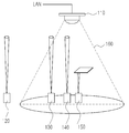
도 1은 본 발명의 일 실시 예에 따른 가시광 통신을 이용한 무선랜 시스템에서 모바일 노드의 상태를 나타낸 예시도이다. 도 1을 참조하면, 본 발명의 일 실시 예에 따른 가시광 통신 무선랜 시스템은 무선랜과 연결된 엑세스 포인트(access point)(110)와, 엑세스 포인트(110)의 통신 범위(160)내에서 엑세스 포인트(110)와 통신을 수행하는 모바일 노드(120, 130, 140, 150)를 포함하여 구성된다. 엑세스 포인트(110)는 가시광 통신을 위해 일반적으로 천장과 같은 가시광 신호를 비추기 용이한 위치에 장착될 수 있다. 모바일 노드(120, 130, 140, 150)는 사용자에 의해 위치 이동이 가능하며, 가시광을 통신 매체로 사용하여 무선 통신을 수행한다. 본 발명이 적용되는 가시광 통신을 이용한 무선 랜 시스템은 가시광을 통신 매체로 사용하기 때문에 송수신 단의 위치 및 통신의 경로를 사용자가 눈으로 파악할 수 있다.1 is a diagram illustrating a state of a mobile node in a wireless LAN system using visible light communication according to an embodiment of the present invention. 1, a visible light communication wireless LAN system according to an exemplary embodiment of the present invention includes an
도 1은 엑세스 포인트(110)와 통신하기 위한 각 모바일 노드(120, 130, 140, 150)들의 상태를 도시한다. 1 illustrates the state of each
도 1을 참조하면, 제1상태 모바일 노드(120)는 엑세스 포인트(110)와의 하향 링크와 상향 링크가 모두 성립되지 않은 상태를 나타낸다. 제2상태 모바일 노 드(130)는 엑세스 포인트(110)와의 하향 링크만 성립되고 엑세스 포인트(110)로의 상향 링크는 성립되지 않은 상태를 나타낸다. 제3상태 모바일 노드(140)는 엑세스 포인트(110)와의 하향 링크와 상향 링크가 모두 성립된 상태를 나타낸다. 이 경우 모바일 노드(140)와 엑세스 포인트(110)는 서로 데이터 송수신이 가능하다. 다음 제4상태 모바일 노드(150)는 엑세스 포인트(110)와의 하향 링크와 상향 링크가 모두 성립되었으나 중간에 특정 장애물로 인해 상향 링크가 잠시 끊어진 상태이다.Referring to FIG. 1, the first state
도 2는 본 발명의 일 실시 예에 따른 가시광 통신 송수신 장치를 나타낸 블록 구성도이다. 상기 도 1의 모바일 노드(120, 130, 140, 150)와 엑세스 포인트(110)는 가시광 통신을 수행하기 위해 도 2에 도시한 바와 같은 가시광 통신 송수신 장치를 포함하여 구성될 수 있다. 본 발명의 일 실시 예에 따른 가시광 통신 송수신 장치(200)는 제어부(210), 가시광 통신 송신부(212)와 가시광 통신 수신부(214), 펄스 생성부(222) 및 펄스 복구부(224), 변조부(232), 복조부(234)를 포함하여 구성된다. 2 is a block diagram illustrating a visible light communication transceiver according to an embodiment of the present invention. The
상기 제어부(210)는 가시광 송수신 장치(200)의 전반적인 제어 동작을 수행하고, 가시광 통신을 통해 수신된 데이터를 메모리부(240)에 저장한다. 특히 본 발명에서 제어부(210)는 모바일 노드에 장착되어 동작시 엑세스 포인트로부터 미니 슬롯을 할당 받으면 할당 받은 미니 슬롯을 통해 일정한 주기로 신호를 송신하도록 제어한다. 상기 신호를 송신하는 주기는 상향 링크의 상태를 파악하기에 적절하도록 시스템 상황에 따라 조절할 수 있다. The
상기 펄스 생성부(222)는 제어부(210)의 제어하에 전송을 위한 데이터에 대 응되는 펄스 신호를 생성하여 변조부(232)로 출력한다.The
상기 변조부(232)는 입력되는 펄스 신호를 가시광 통신에 적합한 신호로 변조하여 가시광 통신 송신부(212)로 출력한다.The
상기 가시광 통신 송신부(212)는 제어부(210)의 제어 신호에 따라 해당 가시광 신호를 출력한다. 이러한 가시광 통신 송신부(212)는 광원으로는 LD(Laser Diode), LED(Light Emitting Diode) 또는 이들의 집합(Array)을 사용하여 구성될 수 있다. 특히 본 발명의 일 실시 예에서는 가시광 송수신 장치(200)가 모바일 노드에 장착되어 동작시, 상향 링크가 설정되지 않은 경우, 사용자에게 상향 링크 설정을 위한 가시성을 제공하기 위해 가시광 신호를 발생시킬 수 있다. The visible light
상기 가시광 통신 수신부(214)는 입력된 가시광 신호를 전기 신호로 변환하여 출력한다. 이때, 가시광 통신 수신부(214)는 외부에 빛이 입력되면 전기적인 신호로 변환하는 포토 다이오드(Photo Diode)로 구성될 수 있다.The visible
상기 복조부(234)는 입력받은 전기 신호를 가시광 통신 방식에 따른 데이터로 복조한 후 펄스 복구부(224)로 출력한다. 그러면, 펄스 복구부(224)는 입력되는 전기 신호를 펄스 신호로 복구하여 제어부(210)로 출력한다.The demodulating
도 3은 본 발명의 일 실시 예에 따른 가시광 통신을 이용한 무선랜 시스템에서 사용되는 가시광 통신 프레임을 나타내는 예시도이다.3 is an exemplary view illustrating a visible light communication frame used in a wireless local area network (LAN) system using visible light communication according to an exemplary embodiment of the present invention.
도 3을 참조하면, 하향 링크를 통해 전송되는 프레임은 제어 정보(310)와 복수의 하향 링크 슬롯(320)을 포함하여 구성된다. 제어 정보(310)는 상향 링크와 하향 링크 슬롯의 전송속도, 슬롯 타입, 슬롯의 할당에 대한 정보를 포함한다. Referring to FIG. 3, a frame transmitted through a downlink includes control information 310 and a plurality of downlink slots 320. The control information 310 includes information on the transmission rate, slot type, and slot allocation of the uplink and downlink slots.
상향 링크를 통해 전송되는 프레임은 경쟁(contention) 슬롯(330)과 복수의 상향 링크 슬롯(340)을 포함하여 구성된다. 경쟁 슬롯(330)은 아직 시스템에 접속하지 않은 모바일 노드가 초기 자원요청을 위해 사용할 수 있는 슬롯이다. The frame transmitted through the uplink includes a contention slot 330 and a plurality of uplink slots 340. The contention slot 330 is a slot that a mobile node that has not yet connected to the system can use for an initial resource request.
본 발명은 본 발명의 특징에 따라 엑세스 포인트가 경쟁 슬롯을 구성하는 미니 슬롯을 접속을 시도한 모바일 노드에게 고정적으로 할당하며, 주기적으로 할당된 미니 슬롯을 통해 모바일 노드가 주기적으로 엑세스 포인트에게 신호를 전송 하도록 한다. 이에 따라 엑세스 포인트는 할당된 미니 슬롯을 통한 수신되는 신호를 이용하여 상향 링크 성립과 상향 링크의 채널 상태를 파악한다. According to an aspect of the present invention, an access point fixedly allocates a minislot constituting a contention slot to a mobile node attempting to connect, and periodically transmits a signal to the access point through a periodically allocated minislot . Accordingly, the access point uses the signal received through the allocated minislot to ascertain the uplink state and the channel state of the uplink.
만약 약속된 시간에 모바일 노드가 고정 할당된 미니 슬롯을 통해 신호를 전송하지 않는 경우 상향 링크의 방향이 맞지 않는 제2상태이거나, 장애물로 인해 상향 링크가 단절된 제4상태로 판단하여 모바일 노드에게 상향 링크 연결이 끊어졌음을 알리는 메시지를 전송한다. 아울러 엑세스 포인트는 고정 할당된 미니 슬롯을 통해 수신한 신호를 기반으로 BER(bit error rate)이나 SINR(signal to interference ratio)을 임시로 저장하고 현재 수신한 신호 품질이 이전에 저장해둔 신호 품질보다 미리 설정된 기준 이하로 떨어진 경우 거리나 간섭으로 인하여 모바일 노드의 채널 상태가 변경되었다고 판단하여 하향 링크와 상향 링크 채널 상태 측정 요구 메시지(CQI-REQ, channel quality index request)를 모바일 노드에게 전송한다. If the mobile node does not transmit a signal through the minislot allocated to the mobile node at the appointed time, it is determined that the uplink is in a wrong state or the fourth state in which the uplink is disconnected due to the obstacle. Send a message informing you that the link has been disconnected. In addition, the access point temporarily stores a bit error rate (BER) or a signal to interference ratio (SINR) based on a signal received through a fixedly allocated minislot, and the currently received signal quality is pre- If it is less than the set reference, it is determined that the channel state of the mobile node has changed due to distance or interference, and the downlink and uplink channel quality measurement request message (CQI-REQ) are transmitted to the mobile node.
도 4는 본 발명의 일 실시 예에 따른 가시광 통신을 이용한 무선랜 시스템에서 모바일 노드(410)와 엑세스 포인트(420) 간의 통신 연결의 동작 흐름도이다. 4 is a flowchart illustrating a communication connection between a
먼저 401단계에서 모바일 노드(410)는 초기 접속(initial access)을 위해서 경쟁 슬롯의 미니 슬롯 중 하나를 무작위로 선택하여 신호를 전송한다. 402단계에서 엑세스 포인트는 경쟁 슬롯을 통해 데이터를 수신한 경우 모바일 노드(410)의 초기 접속을 인지하며, 경쟁 슬롯 내의 미니 슬롯 중 하나를 해당 모바일 노드(410)가 전용으로 사용하도록 할당한다. 이 경우 엑세스 포인트(420)는 모바일 노드(410)가 미리 설정된 주기로 할당한 미니 슬롯을 통해 신호를 전송하도록 제어한다. 이 때 미니 슬롯을 통해 주기적으로 전송하는 신호에는 특정 정보를 포함할수 있으며, 단순히 신호의 품질의 측정이 가능하게만 생성하여 전송하게 할 수 있다. 403단계에서 모바일 노드(410)는 초기(최초) 접속 과정 중이므로 상향 링크의 방향 설정을 사용자가 조정하고 있는 상태일 수 있다. 따라서 상향 링크가 완벽히 설정되었는지 확신할 수 없다. 따라서 엑세스 포인트는 연결(association)되지 않은 모바일 노드(410)가 주기적으로 전송하는 미니 슬롯 신호가 미리 설정된 시간 이상 수신이 되고 BER이나 SINR과 같은 신호 품질 또한 미리 설정된 기준 이상으로 품질이 좋다면, 404단계로 진행하여 모바일 노드(410)의 상향 링크가 안정적으로 설정되었다고 판단하고 연결을 위한 자원을 모바일 노드(410)에게 할당한다. 상기 미니 슬롯 신호가 미리 설정된 시간 이상 수신되는지 판단할 시, 미리 설정된 시간은 안정적으로 상향 링크가 설정되었다고 판단할 수 있을 정도의 시간으로 상황에 따라 적절히 설정할 수 있다. 상기 과정을 통해 엑세스 포인트(420)는 데이터 슬롯의 낭비없이 초기접속 모바일 노드(410)의 상태를 판별할 수 있어서 시스템의 자원 낭비를 최소화 하는 동시에 모바일 노드(410)의 상향 링크 상태를 파악할 수 있다. First, in step 401, the
다음 405단계에서는 모바일 노드(410)가 상기 404단계에서 수신한 자원을 이용하여 연결 요청(AS-REQ, association request) 메시지를 엑세스 포인트로 전송한다. 다음 406단계에서는 엑세스 포인트(420)가 연결 요청 메시지(AS-REQ)에 대한 연결 응답(AS-RSP, association reponse) 메시지를 모바일 노드(410)로 전송한다. 다음 407단계에서는 모바일 노드(410)가 연결 확인(AS-ACK, association acknowledge) 메시지를 엑세스 포인트(420)로 전송한다. 이후 모바일 노드(410)와 엑세스 포인트(420)는 상향 및 하향 링크가 모두 성립되어 데이터 송수신을 수행할 수 있다. In step 405, the
도 5는 본 발명의 일 실시 예에 따른 가시광 통신을 이용한 무선랜 시스템에서 통신 연결시 엑세스 포인트의 동작 흐름도이다.5 is a flowchart illustrating an operation of an access point in a communication connection in a wireless LAN system using visible light communication according to an embodiment of the present invention.
도 5를 참조하면, 505단계에서 엑세스 포인트가 모바일 노드로부터 초기 접속을 위한 신호를 수신하면, 510단계에서 엑세스 포인트는 모바일 노드의 초기 접속에 대응하여 해당 모바일 노드에게 경쟁 슬롯의 미니 슬롯중 하나를 고정적으로 할당한다.Referring to FIG. 5, in
다음 515단계에서는 상기 510단계에서 할당한 미니 슬롯을 통해 신호가 주기적으로 미리 설정된 시간 이상 수신되면, 525단계로 진행하여 미니 슬롯을 통해 수신한 신호의 품질이 미리 설정된 기준 이상인지 판단한다. In
상기 515단계에서 할당한 미니 슬롯을 통해 미리 설정된 시간 이상 주기적으로 신호가 수신되지 않으면, 520단계로 진행하여 모바일 노드의 상향 링크의 방향이 잘못되었거나 장애물에 의해 상향 링크가 단절 등의 원인으로 인해 상향 링크 설정이 실패된 것으로 판단하고 상향 링크 설정 실패 메시지(UL unsync Indication)를 모바일 노드로 전송하고, 505단계로 진행한다. If a signal is not received periodically over a predetermined period of time through the minislot allocated in
상기 515단계에서는 미리 설정된 시간 이상 할당한 미니 슬롯을 통해 신호가 반복적으로 수신되면 상향 링크 설정 메시지(UL sync Indication)를 모바일 노드에게 송신하고, 미리 설정된 시간 이상 할당한 미니 슬롯을 통해 주기적으로 신호가 수신되지 않으면 상향 링크 설정 실패 메시지(UL unsync Indication)를 모바일 노드에게 송신한다. 한편 모바일 노드는 엑세스 포인트로부터 상기 상향 링크 설정 메시지를 수신하면 사용자에게 모바일 노드의 상하향 링크가 모두 연결된 현재 상태를 알리기 위해 'DL/UL sync' 표시를 점멸한다. 또한 모바일 노드가 엑세스 포인트로부터 상향 링크 설정 실패 메시지를 수신하면 사용자에게 모바일 노드의 하향 링크만 연결된 현재 상태를 알리기 위해 'DL sync' 표시를 점멸한다. 또한, 모바일 노드의 가시광 송수신 장치 혹은 가시광 PHY 영역을 이용하여 가시광 신호를 발생시키도록 제어하여 상향 링크를 조정할 수 있도록 가시성을 제공할 수 있다. 상기 'DL sync', 'DL/UL sync' 표시는 모바일 노드가 사용자에게 통신 링크의 상태를 알리기 위해 표시하는 신호로써, 화면, 발광체, 신호음 등을 이용하여 사용자가 인지 가능하도록 구성할 수 있다. In
상기 525단계에서 할당한 미니 슬롯을 통해 수신한 신호의 품질이 미리 설정된 기준 이하이면 530단계로 진행하여 CQI-REQ(channel quality index request) 메시지를 모바일 노드로 전송하여 채널의 품질을 측정하도록 한다. 다음 535단계로 진행하여 모바일 노드로부터 CQI-RSP(channel quality index response) 메시지를 수신하고 505단계로 진행한다. 엑세스 포인트는 수신한 채널 품질 측정 결과를 이용하여 모바일 노드의 전송률이나 duplex 모드를 변경하게 할 수 있다. If the quality of the signal received through the minislot allocated in
상기 525단계에서 할당한 미니 슬롯을 통해 수신한 신호의 품질이 미리 설정된 기준 이상이면 540단계로 진행하여 모바일 노드에게 연결을 위한 자원을 할당하고, 545단계에서 연결 요청을 수신하며, 550단계에서 이에 대한 연결 응답을 전송하며, 555단계에서는 연결 확인을 수신한다. If the quality of the signal received through the minislot allocated in
한편, 상기 도 5에서 설명한 동작은 초기 연결을 수행하는 동작 과정을 예로 들어 설명하였으나, 엑세스 포인트는 통신이 수행중에도 515단계 및 525단계를 수행하여 주기적으로 할당한 미니 슬롯을 통해 신호가 수신되는지 판단하여 상향 링크의 상태를 계속적으로 파악하며, 그에 대응하여 520단계나 530~535단계와 같은 동작을 수행할 수 있다. 이에 따라 본 발명은 상기와 같은 모바일 노드가 초기 접속을 완료하지 않은 상태나 연결(association)이 완료한 후 데이터 송수신이 없어 상향 링크의 상태 파악이 어려운 모바일 노드들까지 상향 링크 상태를 정확하게 파악할 수 있으며, 하향 링크를 수신하는 모든 모바일 노드의 사용자에게 통신 링크의 상태를 표시하여 알려줄 수 있다.5, the access point performs
도 6은 본 발명의 일 실시 예에 따른 가시광 통신을 이용한 무선랜 시스템에서 모바일 노드의 가시성 제공 동작의 흐름도이다.6 is a flowchart of a visibility providing operation of a mobile node in a wireless LAN system using visible light communication according to an exemplary embodiment of the present invention.
도 6을 참조하면, 610단계에서 모바일 노드가 엑세스 포인트로부터 하향 링크 신호를 수신하면, 620단계로 진행하여 수신한 하향 링크 신호에 프레임 시작 플래그(frame start flag)가 존재하는지 판단한다. 620단계에서 프레임 시작 플래그 가 존재하지 않으면 610단계로 진행하고, 상기 620단계에서 프레임 시작 플래그가 존재하면 하향 링크 설정이 완료된 것으로 판단하여, 630단계로 진행하여 모바일 노드는 'DL sync' 표시를 점멸하여 하향 링크만 설정되었음을 표시한다. 다음 640단계에서 모바일 노드는 엑세스 포인트로부터 연결을 위한 자원 할당을 수신하거나 상향 링크 연결 메시지(UL sync Indication)가 수신되는지 판단한다. 640단계에서 판단 결과 수신되지 않은 경우, 630단계로 진행하여 'DL sync' 표시를 계속 점멸하며, 640단계에서 판단 결과 수신된 경우에는, 엑세스 포인트와의 상향 및 하향 링크가 모두 설정되었다고 판단하여 650단계로 진행하고 'DL/UL sync' 표시를 점멸하여 표시한다. Referring to FIG. 6, when the mobile node receives a downlink signal from the access point in
다음 660단계에서는 설정된 상하향 링크를 통해 데이터 송수신을 수행한다. 다음 670단계에서는 모바일 노드에 상향 링크 연결 실패 메시지(UL unsync indication)가 수신되는지 판단한다. 상기 670단계에서 상향 링크 연결 실패 메시지가 수신되면 630단계로 진행하여 'DL sync' 표시를 점멸하여 표시하며 상향 링크가 설정되지 않았음을 표시한다. In
상기 670단계에서 상향 링크 연결 실패 메시지가 수신되지 않으면, 680단계로 진행하여 연결이 해제되는지 판단한다. 680단계에서 연결이 해제되면 종료되며, 연결이 해제되지 않으면 660단계로 진행하여 통신을 계속 수행한다. If it is determined in
도 7은 본 발명의 일 실시 예에 따른 가시광 통신을 이용한 무선랜 시스템에서 모바일 노드의 상태 변화를 나타낸 도면이다. 7 is a diagram illustrating a state change of a mobile node in a wireless LAN system using visible light communication according to an embodiment of the present invention.
도 7에 도시한 바와 같이 모바일 노드는 크게 연결 해제 상태(710)와 하향 링크 연결 상태(720)와 상하향 링크 연결 상태(730)로 나눌 수 있다. As shown in FIG. 7, the mobile node can be largely divided into a
처음 연결 해제 상태(710)에서 모바일 노드가 하향 링크로 부터 수신한 신호에 프레임 시작 플래그가 수신되면 하향 링크가 연결된 것이기 때문에 하향 링크 연결 상태(720)가 된다. If the frame start flag is received in the signal received from the downlink in the first
하향 링크 연결 상태(720)에서 하향 링크 신호가 수신되지 않으면 다시 연결 해제 상태(710)가 되며, 하향 링크 연결 상태(720)에서 엑세스 포인트로 부터 상향 링크를 위한 자원을 할당 받거나 상향 링크 연결 메시지(UL sync indication)를 수신하면 상향 링크가 설정된 것이므로 상하향 링크 연결 상태(730)가 된다. When the downlink signal is not received in the
상하향 링크 연결 상태(730)에서 상향링크 설정 실패 메시지(UL unsync indication)를 수신하면 상향 링크가 실패된 것이므로 하향 링크 연결 상태(720)가 되며, 상하향 링크 연결 상태(730)에서 상하향 링크 신호가 모두 수신되지 않으면 연결 해제 상태(710)가 된다. Upon receiving the UL unsuppressed message in the uplink /
상기와 같이 본 발명의 일 실시예에 따른 가시광 통신을 이용한 무선 랜 시스템에서 통신 채널의 상태 표시 방법 및 장치의 동작 및 구성이 이루어질 수 있으며, 한편 상기한 본 발명의 설명에서는 구체적인 실시 예에 관해 설명하였으나 여러 가지 변형이 본 발명의 범위를 벗어나지 않고 실시될 수 있다.As described above, in the wireless LAN system using the visible light communication according to the embodiment of the present invention, the operation and configuration of the method and apparatus for displaying the state of the communication channel can be performed, and in the description of the present invention, But various modifications may be made without departing from the scope of the present invention.
도 1은 본 발명의 일 실시 예에 따른 가시광 통신을 이용한 무선랜 시스템에서 모바일 노드의 상태를 나타낸 예시도1 is an exemplary diagram illustrating a state of a mobile node in a wireless LAN system using visible light communication according to an embodiment of the present invention.
도 2는 본 발명의 일 실시 예에 따른 가시광 통신 송수신 장치를 나타낸 블록 구성도2 is a block diagram illustrating a visible light communication transceiver according to an embodiment of the present invention.
도 3은 본 발명의 일 실시 예에 따른 가시광 통신을 이용한 무선랜 시스템에서 사용되는 가시광 통신 프레임을 나타내는 예시도3 is an exemplary diagram illustrating a visible light communication frame used in a wireless LAN system using visible light communication according to an embodiment of the present invention.
도 4는 본 발명의 일 실시 예에 따른 가시광 통신을 이용한 무선랜 시스템에서 모바일 노드와 엑세스 포인트 간의 통신 연결의 동작 흐름도FIG. 4 is a flowchart illustrating a communication connection between a mobile node and an access point in a wireless LAN system using visible light communication according to an exemplary embodiment of the present invention.
도 5는 본 발명의 일 실시 예에 따른 가시광 통신을 이용한 무선랜 시스템에서 통신 연결시 엑세스 포인트의 동작 흐름도5 is a flowchart illustrating an operation flow of an access point in a communication connection in a wireless LAN system using visible light communication according to an exemplary embodiment of the present invention.
도 6은 본 발명의 일 실시 예에 따른 가시광 통신을 이용한 무선랜 시스템에서 모바일 노드의 가시성 제공 동작의 흐름도 6 is a flowchart of a visibility providing operation of a mobile node in a wireless LAN system using visible light communication according to an embodiment of the present invention.
도 7은 본 발명의 일 실시 예에 따른 가시광 통신을 이용한 무선랜 시스템에서 모바일 노드의 상태 변화를 나타낸 도면7 is a diagram illustrating a state change of a mobile node in a wireless LAN system using visible light communication according to an embodiment of the present invention.
Claims (24)
Priority Applications (1)
| Application Number | Priority Date | Filing Date | Title |
|---|---|---|---|
| KR1020090038343A KR101530096B1 (en) | 2009-04-30 | 2009-04-30 | Method and system for recognizing state of uplink in wireless local area network using visible light communication |
Applications Claiming Priority (1)
| Application Number | Priority Date | Filing Date | Title |
|---|---|---|---|
| KR1020090038343A KR101530096B1 (en) | 2009-04-30 | 2009-04-30 | Method and system for recognizing state of uplink in wireless local area network using visible light communication |
Publications (2)
| Publication Number | Publication Date |
|---|---|
| KR20100119301A KR20100119301A (en) | 2010-11-09 |
| KR101530096B1 true KR101530096B1 (en) | 2015-06-18 |
Family
ID=43405390
Family Applications (1)
| Application Number | Title | Priority Date | Filing Date |
|---|---|---|---|
| KR1020090038343A Expired - Fee Related KR101530096B1 (en) | 2009-04-30 | 2009-04-30 | Method and system for recognizing state of uplink in wireless local area network using visible light communication |
Country Status (1)
| Country | Link |
|---|---|
| KR (1) | KR101530096B1 (en) |
Citations (4)
| Publication number | Priority date | Publication date | Assignee | Title |
|---|---|---|---|---|
| KR20080049506A (en) * | 2006-11-30 | 2008-06-04 | 삼성전자주식회사 | Communication link connection method using visible light communication |
| KR20080104663A (en) * | 2007-05-28 | 2008-12-03 | 삼성전자주식회사 | Communication link connection method in wireless LAN system using visible light communication |
| KR20090009483A (en) * | 2007-07-20 | 2009-01-23 | 삼성전자주식회사 | Method for displaying mobile node status in wireless LAN system using visible light communication and apparatus for same |
| KR20090027942A (en) * | 2007-09-13 | 2009-03-18 | 삼성전자주식회사 | Method and device for data retransmission in wireless LAN system using visible light communication |
-
2009
- 2009-04-30 KR KR1020090038343A patent/KR101530096B1/en not_active Expired - Fee Related
Patent Citations (4)
| Publication number | Priority date | Publication date | Assignee | Title |
|---|---|---|---|---|
| KR20080049506A (en) * | 2006-11-30 | 2008-06-04 | 삼성전자주식회사 | Communication link connection method using visible light communication |
| KR20080104663A (en) * | 2007-05-28 | 2008-12-03 | 삼성전자주식회사 | Communication link connection method in wireless LAN system using visible light communication |
| KR20090009483A (en) * | 2007-07-20 | 2009-01-23 | 삼성전자주식회사 | Method for displaying mobile node status in wireless LAN system using visible light communication and apparatus for same |
| KR20090027942A (en) * | 2007-09-13 | 2009-03-18 | 삼성전자주식회사 | Method and device for data retransmission in wireless LAN system using visible light communication |
Also Published As
| Publication number | Publication date |
|---|---|
| KR20100119301A (en) | 2010-11-09 |
Similar Documents
| Publication | Publication Date | Title |
|---|---|---|
| KR101376375B1 (en) | Method and apparatus for indication status of mobile node in wireless local area network using visible light communication | |
| US8452188B2 (en) | Visible light communication method and system | |
| US8428469B2 (en) | Visible light communication method and apparatus | |
| KR101683881B1 (en) | Method and apparatus for transmitting decision of visibility frame in transmitter and receiver of visible light communications | |
| KR101708937B1 (en) | Method and apparatus for recovering link in visible light communication system | |
| KR101615762B1 (en) | Method and apparatus for transmmiting of visibility frame in multi mode visible light communications | |
| US8488976B2 (en) | Apparatus and method for supporting mobility of a mobile terminal that performs visible light communication | |
| US8792790B2 (en) | Apparatus and method for supporting mobility of a mobile terminal that performs visible light communication | |
| US20090269073A1 (en) | Transmitter apparatus and communication system | |
| CN107040946B (en) | L IFI communication technology-based conversion method and system | |
| KR20090027942A (en) | Method and device for data retransmission in wireless LAN system using visible light communication | |
| KR100876725B1 (en) | Communication link connection method in wireless LAN system using visible light communication | |
| US8942254B2 (en) | Method for transmitting/receiving data while supporting scalability in communication system | |
| Alawadhi et al. | A survey on IEEE 802.15. 7 MAC protocols for visible light communication | |
| KR101530096B1 (en) | Method and system for recognizing state of uplink in wireless local area network using visible light communication | |
| CN218868231U (en) | Optical fidelity Li-Fi communication system | |
| KR20110031264A (en) | Fractional Resource Allocation Device and Method in Visible Light Communication System | |
| KR101769619B1 (en) | Apparatus and method for resource allocation in transmitter and receiver system of visible light communications | |
| CN111431597A (en) | A vehicle networking data communication network and method based on retro-reflection device communication | |
| KR20120028781A (en) | Apparatus and method for supporting mobility of mobile terminal performing visible light communication |
Legal Events
| Date | Code | Title | Description |
|---|---|---|---|
| PA0109 | Patent application |
St.27 status event code: A-0-1-A10-A12-nap-PA0109 |
|
| PG1501 | Laying open of application |
St.27 status event code: A-1-1-Q10-Q12-nap-PG1501 |
|
| R18-X000 | Changes to party contact information recorded |
St.27 status event code: A-3-3-R10-R18-oth-X000 |
|
| R18-X000 | Changes to party contact information recorded |
St.27 status event code: A-3-3-R10-R18-oth-X000 |
|
| A201 | Request for examination | ||
| PA0201 | Request for examination |
St.27 status event code: A-1-2-D10-D11-exm-PA0201 |
|
| D13-X000 | Search requested |
St.27 status event code: A-1-2-D10-D13-srh-X000 |
|
| D14-X000 | Search report completed |
St.27 status event code: A-1-2-D10-D14-srh-X000 |
|
| PN2301 | Change of applicant |
St.27 status event code: A-3-3-R10-R13-asn-PN2301 St.27 status event code: A-3-3-R10-R11-asn-PN2301 |
|
| R18-X000 | Changes to party contact information recorded |
St.27 status event code: A-3-3-R10-R18-oth-X000 |
|
| E701 | Decision to grant or registration of patent right | ||
| PE0701 | Decision of registration |
St.27 status event code: A-1-2-D10-D22-exm-PE0701 |
|
| GRNT | Written decision to grant | ||
| PR0701 | Registration of establishment |
St.27 status event code: A-2-4-F10-F11-exm-PR0701 |
|
| PR1002 | Payment of registration fee |
St.27 status event code: A-2-2-U10-U11-oth-PR1002 Fee payment year number: 1 |
|
| PG1601 | Publication of registration |
St.27 status event code: A-4-4-Q10-Q13-nap-PG1601 |
|
| P22-X000 | Classification modified |
St.27 status event code: A-4-4-P10-P22-nap-X000 |
|
| FPAY | Annual fee payment |
Payment date: 20180530 Year of fee payment: 4 |
|
| PR1001 | Payment of annual fee |
St.27 status event code: A-4-4-U10-U11-oth-PR1001 Fee payment year number: 4 |
|
| R18-X000 | Changes to party contact information recorded |
St.27 status event code: A-5-5-R10-R18-oth-X000 |
|
| FPAY | Annual fee payment |
Payment date: 20190530 Year of fee payment: 5 |
|
| PR1001 | Payment of annual fee |
St.27 status event code: A-4-4-U10-U11-oth-PR1001 Fee payment year number: 5 |
|
| PN2301 | Change of applicant |
St.27 status event code: A-5-5-R10-R13-asn-PN2301 St.27 status event code: A-5-5-R10-R11-asn-PN2301 |
|
| R18-X000 | Changes to party contact information recorded |
St.27 status event code: A-5-5-R10-R18-oth-X000 |
|
| PC1903 | Unpaid annual fee |
St.27 status event code: A-4-4-U10-U13-oth-PC1903 Not in force date: 20200613 Payment event data comment text: Termination Category : DEFAULT_OF_REGISTRATION_FEE |
|
| PC1903 | Unpaid annual fee |
St.27 status event code: N-4-6-H10-H13-oth-PC1903 Ip right cessation event data comment text: Termination Category : DEFAULT_OF_REGISTRATION_FEE Not in force date: 20200613 |
|
| R18-X000 | Changes to party contact information recorded |
St.27 status event code: A-5-5-R10-R18-oth-X000 |
|
| R18-X000 | Changes to party contact information recorded |
St.27 status event code: A-5-5-R10-R18-oth-X000 |