KR101485143B1 - Check valve - Google Patents
Check valve Download PDFInfo
- Publication number
- KR101485143B1 KR101485143B1 KR1020120123333A KR20120123333A KR101485143B1 KR 101485143 B1 KR101485143 B1 KR 101485143B1 KR 1020120123333 A KR1020120123333 A KR 1020120123333A KR 20120123333 A KR20120123333 A KR 20120123333A KR 101485143 B1 KR101485143 B1 KR 101485143B1
- Authority
- KR
- South Korea
- Prior art keywords
- valve plug
- valve
- pressure fluid
- check valve
- stopper
- Prior art date
- Legal status (The legal status is an assumption and is not a legal conclusion. Google has not performed a legal analysis and makes no representation as to the accuracy of the status listed.)
- Active
Links
- 239000012530 fluid Substances 0.000 claims abstract description 56
- 238000004891 communication Methods 0.000 claims abstract description 24
- 230000008878 coupling Effects 0.000 claims description 20
- 238000010168 coupling process Methods 0.000 claims description 20
- 238000005859 coupling reaction Methods 0.000 claims description 20
- 230000002093 peripheral effect Effects 0.000 claims description 15
- 238000000034 method Methods 0.000 claims description 11
- 229920005989 resin Polymers 0.000 claims description 11
- 239000011347 resin Substances 0.000 claims description 11
- 239000000463 material Substances 0.000 claims description 10
- 230000007246 mechanism Effects 0.000 claims description 6
- 230000001681 protective effect Effects 0.000 claims description 5
- 238000011144 upstream manufacturing Methods 0.000 abstract description 7
- 238000007789 sealing Methods 0.000 description 7
- 230000006835 compression Effects 0.000 description 5
- 238000007906 compression Methods 0.000 description 5
- 230000008859 change Effects 0.000 description 4
- 238000004519 manufacturing process Methods 0.000 description 4
- 230000000694 effects Effects 0.000 description 2
- 230000009471 action Effects 0.000 description 1
- 239000007769 metal material Substances 0.000 description 1
- 230000000149 penetrating effect Effects 0.000 description 1
- 230000008569 process Effects 0.000 description 1
- 230000001105 regulatory effect Effects 0.000 description 1
- 230000001846 repelling effect Effects 0.000 description 1
- 230000008961 swelling Effects 0.000 description 1
- 229920003002 synthetic resin Polymers 0.000 description 1
- 239000000057 synthetic resin Substances 0.000 description 1
- 239000010409 thin film Substances 0.000 description 1
Images
Classifications
-
- F—MECHANICAL ENGINEERING; LIGHTING; HEATING; WEAPONS; BLASTING
- F16—ENGINEERING ELEMENTS AND UNITS; GENERAL MEASURES FOR PRODUCING AND MAINTAINING EFFECTIVE FUNCTIONING OF MACHINES OR INSTALLATIONS; THERMAL INSULATION IN GENERAL
- F16K—VALVES; TAPS; COCKS; ACTUATING-FLOATS; DEVICES FOR VENTING OR AERATING
- F16K15/00—Check valves
- F16K15/14—Check valves with flexible valve members
- F16K15/144—Check valves with flexible valve members the closure elements being fixed along all or a part of their periphery
-
- F—MECHANICAL ENGINEERING; LIGHTING; HEATING; WEAPONS; BLASTING
- F16—ENGINEERING ELEMENTS AND UNITS; GENERAL MEASURES FOR PRODUCING AND MAINTAINING EFFECTIVE FUNCTIONING OF MACHINES OR INSTALLATIONS; THERMAL INSULATION IN GENERAL
- F16K—VALVES; TAPS; COCKS; ACTUATING-FLOATS; DEVICES FOR VENTING OR AERATING
- F16K15/00—Check valves
- F16K15/02—Check valves with guided rigid valve members
- F16K15/06—Check valves with guided rigid valve members with guided stems
- F16K15/063—Check valves with guided rigid valve members with guided stems the valve being loaded by a spring
-
- F—MECHANICAL ENGINEERING; LIGHTING; HEATING; WEAPONS; BLASTING
- F16—ENGINEERING ELEMENTS AND UNITS; GENERAL MEASURES FOR PRODUCING AND MAINTAINING EFFECTIVE FUNCTIONING OF MACHINES OR INSTALLATIONS; THERMAL INSULATION IN GENERAL
- F16K—VALVES; TAPS; COCKS; ACTUATING-FLOATS; DEVICES FOR VENTING OR AERATING
- F16K27/00—Construction of housing; Use of materials therefor
- F16K27/02—Construction of housing; Use of materials therefor of lift valves
- F16K27/0209—Check valves or pivoted valves
-
- F—MECHANICAL ENGINEERING; LIGHTING; HEATING; WEAPONS; BLASTING
- F16—ENGINEERING ELEMENTS AND UNITS; GENERAL MEASURES FOR PRODUCING AND MAINTAINING EFFECTIVE FUNCTIONING OF MACHINES OR INSTALLATIONS; THERMAL INSULATION IN GENERAL
- F16K—VALVES; TAPS; COCKS; ACTUATING-FLOATS; DEVICES FOR VENTING OR AERATING
- F16K31/00—Actuating devices; Operating means; Releasing devices
- F16K31/44—Mechanical actuating means
- F16K31/50—Mechanical actuating means with screw-spindle or internally threaded actuating means
-
- Y—GENERAL TAGGING OF NEW TECHNOLOGICAL DEVELOPMENTS; GENERAL TAGGING OF CROSS-SECTIONAL TECHNOLOGIES SPANNING OVER SEVERAL SECTIONS OF THE IPC; TECHNICAL SUBJECTS COVERED BY FORMER USPC CROSS-REFERENCE ART COLLECTIONS [XRACs] AND DIGESTS
- Y10—TECHNICAL SUBJECTS COVERED BY FORMER USPC
- Y10T—TECHNICAL SUBJECTS COVERED BY FORMER US CLASSIFICATION
- Y10T137/00—Fluid handling
- Y10T137/7722—Line condition change responsive valves
- Y10T137/7837—Direct response valves [i.e., check valve type]
- Y10T137/7879—Resilient material valve
Landscapes
- Engineering & Computer Science (AREA)
- General Engineering & Computer Science (AREA)
- Mechanical Engineering (AREA)
- Check Valves (AREA)
- Valve Housings (AREA)
- Lift Valve (AREA)
- Multiple-Way Valves (AREA)
Abstract
본 발명은 체크 밸브에 관한 것이며, 체크 밸브(10)는, 상류측에 설치되는 제1 바디(14)와, 상기 제1 바디(14)에 연결되어 하류측에 설치된 제2 바디(18)를 구비하고, 상기 제1 바디(14) 내부에 형성된 연통 챔버(42)에 밸브 플러그(42)가 자유로이 위치 변경 가능하게 설치된다. 밸브 플러그(20)에는, 그 본체부(62)를 밸브 시트면(46)에 안착시키는 방향으로 밀어 붙이는 스커트부(64)를 가지며, 상기 스커트부(64)의 탄성 반발력에 의하여 본체부(62)가 상기 밸브 시트면(46)에 안착된다. 그리고, 제1 바디(14)에 압력 유체가 공급됨으로써 밸브 플러그(20)가 스커트부(64)의 탄성 반발력에 저항하여 위치 변경하고, 제1 바디(14)의 내부와 제2 바디(18)의 내부가 연통하여 압력 유체가 유통한다.The check valve (10) comprises a first body (14) provided on the upstream side and a second body (18) connected to the first body (14) And a valve plug 42 is freely and positionally installed in a communication chamber 42 formed in the first body 14. The valve plug 20 has a skirt portion 64 which is pushed in a direction to seat the main body portion 62 on the valve seat surface 46. The resilient repulsive force of the skirt portion 64 causes the main body portion 62 Is seated on the valve seat surface (46). The pressure fluid is supplied to the first body 14 so that the valve plug 20 is displaced against the resilient repulsive force of the skirt portion 64 and the inside of the first body 14 and the second body 18, So that the pressure fluid flows.
Description
본 발명은 유로를 따라 일방향으로만 압력 유체를 유통시켜 반대 방향으로의 유통을 저지하는 것이 가능한 체크 밸브에 관한 것이다.The present invention relates to a check valve capable of circulating a pressure fluid only in one direction along a flow path to prevent flow in the opposite direction.
본 출원인은, 일본공개특허 특개2003-322264호 공보(특허문헌 1)에서, 바디와, 상기 바디의 양단측에 대향하여 설치되고, 유체압 기기에 자유로이 탈착 가능하게 접속되는 한 조의 커플링부를 가지며, 일측의 유체압 기기로부터 압력 유체의 유통만을 허용하고, 타측의 유체압 기기로부터 압력 유체의 유통을 저지하는 체크 밸브를 제안하였다.Japanese Unexamined Patent Application Publication No. 2003-322264 (Patent Document 1) discloses a vehicle having a body and a pair of coupling portions which are provided opposite to both ends of the body and which are freely detachably connected to the fluid pressure device , A check valve which permits only the flow of the pressure fluid from one fluid pressure device and prevents the flow of the pressure fluid from the other fluid pressure device is proposed.
또한, 일본등록특허 제3369523호공보(특허문헌 2)에 개시된 체크밸브는, 밸브 본체가 상류측 본체와 하류측 본체로 형성되고, 상기 상류측 본체와 하류측 본체가 연결됨과 동시에 상기 밸브 본체의 내부에는, 밸브 플러그와, 합성수지로 압축 코일 스프링 형상으로 형성된 스프링이 수납되고, 상기 스프링의 탄성 반발 작용 하에서 밸브 플러그를 밸브 시트부에 안착시키는 구성으로 되어 있다. 그리고, 상류측 본체의 내부에 압력 유체가 공급됨으로써 밸브 플러그가 스프링의 탄성 반발력에 저항하여 밸브 시트부로부터 이격되고, 상기 압력 유체가 하류측 본체의 내부로 유통된다. 한편, 하류측 본체에 압력 유체가 공급되는 경우에는, 밸브 플러그가 스프링의 탄성 반발력에 의하여 밸브 시트부에 안착된 상태에서 이동하는 일은 없기 때문에 상기 압력 유체가 하류측 본체로부터 상류측 본체로 유통하는 것이 저지된다.The check valve disclosed in Japanese Patent No. 3369523 (Patent Document 2) is characterized in that the valve body is formed of an upstream side body and a downstream side body, and the upstream side body and the downstream side body are connected to each other, A valve plug and a spring formed of a synthetic resin in the form of a compression coil spring are received in the interior of the valve seat so that the valve plug is seated on the valve seat portion under the elastic repulsion action of the spring. Then, the pressure fluid is supplied to the inside of the upstream side body, so that the valve plug is separated from the valve seat portion against the resilient repulsive force of the spring, and the pressure fluid flows into the downstream side main body. On the other hand, when the pressure fluid is supplied to the downstream-side body, since the valve plug does not move in a state of being seated on the valve seat portion due to the elastic repulsive force of the spring, the pressure fluid flows from the downstream- Is blocked.
그러나, 위에서 설명한 특허문헌 2에 따른 체크 밸브는, 밸브 플러그를 밸브 시트부측을 향하여 밀어 붙이기 위하여 압축 코일 스프링인 스프링을 사용하고 있으나, 이러한 스프링은, 수지제이므로, 제조가 매우 어려우며, 이에 따른 제조 비용이 높이 치솟는 문제가 있다. 또한, 밸브 플러그가 밸브 열림 상태가 되었을 때에는, 스프링이 밸브 플러그에 의하여 압축된 상태가 되며, 나선 형상으로 형성된 스프링의 선재 사이가 좁아지게 되고, 압력 유체가 유통할 때의 유로 저항이 되는 것이다. 그 결과, 상류측 본체로부터 하류측 본체로 유통하는 압력 유체의 유량이 감소되어 버리는 문제가 있다.However, the check valve according to Patent Document 2 described above uses a spring that is a compression coil spring for pushing the valve plug toward the valve seat side. However, since such a spring is made of resin, it is very difficult to manufacture, There is a problem that the cost is soared. In addition, when the valve plug is in the valve open state, the spring is compressed by the valve plug, and the space between the spirally formed springs narrows, and the flow path resistance when the pressure fluid flows. As a result, there is a problem that the flow rate of the pressure fluid flowing from the upstream side main body to the downstream side main body is reduced.
그리고, 압력 유체가 스프링의 내부를 통과하도록 유통함으로써 상기 스프링에 대하여 치우침 하중이 부여되고, 상기 스프링의 파손을 초래할 우려가 있다.The pressure fluid is allowed to flow through the inside of the spring, so that a biasing load is applied to the spring, which may cause the spring to break.
본 발명의 목적은 유통 저항을 저감시킴으로써 유체를 원활하게 유통시킴과 동시에 소형화를 도모할 수 있는 체크 밸브를 제공하는 것을 목적으로 한다.An object of the present invention is to provide a check valve capable of smoothly flowing a fluid and reducing its size by reducing the flow resistance.
상기의 목적을 달성하기 위하여, 본 발명은 압력 유체가 공급되는 제1 포트를 가진 제1 바디와,In order to accomplish the above object, the present invention provides a fluid dispenser comprising a first body having a first port to which a pressure fluid is supplied,
상기 제1 바디에 연결되고, 상기 압력 유체가 배출되는 제2 포트를 가지는 제2 바디와,A second body connected to the first body and having a second port through which the pressure fluid is discharged,
상기 제1 및 제2 바디의 내부에 설치되고, 상기 압력 유체가 유통되는 유로의 연통 상태를 절환하는 밸브 플러그와,A valve plug installed inside the first and second bodies for switching a communication state of a flow path through which the pressure fluid flows,
상기 제1 바디에 형성된 밸브 시트부측을 향하여 상기 밸브 플러그를 밀어 붙이고, 상기 밸브 플러그를 상기 밸브 시트부에 안착시키는 탄성반발수단을 구비하며,And elastic resilience means for pushing the valve plug toward the valve seat portion formed on the first body and seating the valve plug on the valve seat portion,
상기 탄성반발수단은, 상기 제2 바디에 보호 유지되는 보호 유지부와, 상기 보호 유지부에 접합되고 상기 밸브 플러그를 상기 제2 바디로부터 이격되는 방향을 향하여 밀어 붙이는 시트 형상의 탄성반발부를 가지며, 상기 탄성반발부에는, 상기 압력 유체가 유통하는 홀 부가 형성되는 것을 특징으로 한다.Wherein the elastic resilience means has a protective holding portion that is protected by the second body and a sheet-like elastic resilience portion which is joined to the protective holding portion and which pushes the valve plug in a direction away from the second body, And the elastic repulsion portion is formed with a hole portion through which the pressure fluid flows.
본 발명에 의하면, 제1 바디와 제2 바디가 연결되어 그 내부에 압력 유체가 유통하는 유로의 연통 상태를 절환하는 밸브 플러그를 상기 제1 및 제2 바디의 내부에 구비한 체크 밸브에 있어서, 상기 제1 바디에 형성된 밸브 시트부측을 향하여 상기 밸브 플러그를 밀어 붙이고, 상기 밸브 플러그를 상기 밸브 시트부에 안착시키는 탄성반발수단을 구비하고, 상기 탄성반발수단은, 그 보호 유지부가 상기 제2 바디에 보호 유지됨과 동시에 상기 보호 유지부에 접합되는 시트 형상의 탄성 반발부가 상기 압력 유체가 유통하는 홀 부를 가지며, 상기 밸브 플러그를 상기 제2 바디로부터 이격시키는 방향을 향하여 밀어 붙인다.According to the present invention, there is provided a check valve having a valve plug connected to a first body and a second body so as to switch a communication state of a flow path through which a pressure fluid flows, in a first body and a second body, And an elastic resilience means for pushing the valve plug toward the valve seat portion formed on the first body and seating the valve plug on the valve seat portion, Shaped resilient bounce portion joined to the protective holding portion has a hole portion through which the pressure fluid flows and pushes the valve plug toward the direction of separating the valve plug from the second body.
따라서, 밸브 플러그를 안착시킬 때의 힘을 밀어 붙이기 위하여 압축 코일 스프링으로 이루어진 스프링을 형성하는 대신에 탄성 반발력을 가진 시트 형상의 탄성 반발부를 형성하여 밸브 플러그를 밀어 붙임으로써 구성의 간소화를 도모할 수 있고, 이에 따라 소형화를 도모할 수 있다. 또한, 탄성 반발부에는 홀 부가 형성되어 있으므로, 밸브 플러그가 밸브 시트부로부터 이격하여 압력 유체의 유통 상태에서도 상기 압력 유체가 상기 홀 부를 통하여 확실하고 적절하게 하류측으로 유통할 수 있기 때문에, 종래기술에 따른 체크 밸브와 같은 유통 저항을 발생시키는 일이 없이 상기 압력 유체를 원활하게 유통시킬 수 있다.Therefore, instead of forming a spring made of a compression coil spring to push the force when the valve plug is seated, a sheet-like resilient repulsion part having an elastic repulsive force is formed and the valve plug is pushed out to simplify the configuration Therefore, miniaturization can be achieved. Since the hole portion is formed in the resilient repulsion portion, the pressure fluid can be surely and appropriately flowed to the downstream side through the hole portion even when the valve plug is separated from the valve seat portion and the pressure fluid is circulated. It is possible to smoothly flow the pressure fluid without generating a flow resistance like the check valve according to the present invention.
그리고, 탄성 반발부를 밸브 플러그와 일체적으로 형성함으로써 제1 및 제2 바디에 대하여 밸브 플러그를 조립하는 것과 동시에 탄성 반발부를 조립하는 것이 가능하게 되어 그 제조가 용이해지며, 이에 따라 제조 비용의 삭감을 도모할 수 있으므로, 저렴한 체크 밸브를 제조할 수 있다.By forming the resilient repulsive portion integrally with the valve plug, it is possible to assemble the resilient repulsive portion at the same time as assembling the valve plug with respect to the first and second bodies, thereby facilitating the manufacture thereof, It is possible to manufacture an inexpensive check valve.
또한 바디, 밸브 플러그 및 탄성 반발부를 각각 수지제 재료로 형성하여도 좋다.Further, the body, the valve plug, and the elastic repulsion may be made of a resin material, respectively.
또한, 제1 바디와 제2 바디는 각각에 형성된 나사부를 상호 나사 결합시킴으로써 연결되고, 상기 나사부를 사다리꼴 나사(trapezoidal screw)로 형성하여도 좋다. 따라서, 제1 바디와 제2 바디의 연결을 확실하고 견고하게 할 수 있으면서도 사다리꼴 나사를 채용함으로써 나사부끼리의 풀림을 억제할 수 있다.The first body and the second body may be connected to each other by screwing the threaded portions formed thereon, and the threaded portion may be formed of a trapezoidal screw. Therefore, although the connection between the first body and the second body can be made firm and firm, the use of a trapezoidal screw can be used to suppress the loosening of the threaded portions.
그리고, 제1 바디와 제2 바디의 연결 부의에는, 상기 제1 및 제2 바디의 축선과 직교 방향으로 삽입되어 결합되는 멈춤핀을 설치하여도 좋다. 따라서, 제1 바디와 제2 바디가 연결되는 때, 그 축선과 직교 방향으로 멈춤핀을 삽입하여 결합시킴으로써 상기 제1 및 제2 바디와 축 방향으로의 상대적인 위치 변경을 확실하게 저지할 수 있다. 그 결과, 예를 들면 체크 밸브가 진동 등이 발생하는 환경에서 사용되는 경우에도 제1 바디와 제2 바디의 연결이 풀리는 일 이 없어 적합한다.A connecting pin of the first body and the second body may be provided with a detent pin inserted and coupled in a direction orthogonal to the axis of the first and second bodies. Therefore, when the first body and the second body are connected, the stop pin is inserted and coupled in a direction orthogonal to the axis, so that the relative positional change with respect to the first and second bodies in the axial direction can be reliably prevented. As a result, for example, even when the check valve is used in an environment where vibration or the like is generated, the connection between the first body and the second body is not released, which is suitable.
그리고, 제1 바디 또는 제2 바디 중 어느 일측의 단부 외주면에는, 반경 외측 방향으로 돌출된 돌기부가 형성되고, 상기 돌기부를 가진 상기 제1 바디 또는 제2 바디 중 어느 일측과는 반대가 되는 상기 제2 바디 또는 제1 바디에 상기 단부가 밀어 넣어지는 홈부를 형성하여도 좋다. 따라서, 제1 바디와 제2 바디를 연결할 때, 단부의 선단부가 압입홈에 밀어 넣어짐과 동시에 단부 외주면의 돌기부가 상기 압입홈에 슬라이딩하여 접하여 눌려지고 밀려지게 되므로, 상기 제1 바디와 제2 바디를 더욱 확실하고 견고하게 연결할 수 있으면서 상기 제1 바디와 제2 바디 사이의 밀폐를 확실하게 실시할 수 있다.A protrusion protruding in a radially outward direction is formed on an outer circumferential surface of an end of either one of the first body and the second body, and the protrusion protruding in a radially outward direction is formed on the outer circumferential surface of the first body or the second body. 2 The body or the first body may be formed with a groove portion into which the end portion is pushed. Therefore, when the first body and the second body are connected to each other, the tip of the end portion is pushed into the press-fit groove and the protrusion of the outer peripheral surface of the end slides on the press-fit groove to be pressed and pushed. It is possible to more firmly and firmly connect the body and to seal the first body and the second body with certainty.
본 발명에 따르면, 이하의 효과를 얻을 수 있다.According to the present invention, the following effects can be obtained.
즉, 밸브 플러그를 안착시킬 때의 힘을 밀어 붙이기 위하여 수지제의 압축 코일 스프링으로 이루어진 스프링을 설치하는 대신에, 탄성 반발력을 지닌 시트 형상의 탄성 반발부를 설치하여 밸브 플러그를 밀어 붙임으로써 구성을 간소화할 수 있으며, 이에 따라 소형화를 도모할 수 있다. 또한, 탄성 반발부에는 홀 부가 형성되어 있으므로, 밸브 플러그가 밸브 시트부로부터 이격되어 압력 유체가 유통 상태에 있더라도 상기 압력 유체가 상기 홀 부를 통하여 확실하고 적절하게 하류측으로 유통할 수 있으므로, 종래기술에 따른 체크 밸브와 같은 유통 저항이 일어나는 일이 없이 상기 압력 유체를 원활하게 유통시킬 수 있게 된다.In other words, instead of providing a spring made of resin compression coil spring for pushing the valve plug at the time of seating the valve plug, a sheet-shaped resilient repulsion unit having an elastic repulsive force is provided to push the valve plug to simplify the structure Therefore, miniaturization can be achieved. Since the hole portion is formed in the resilient repulsion portion, the pressure fluid can be reliably and appropriately flowed to the downstream side even if the valve plug is separated from the valve seat portion and the pressure fluid is in the circulation state. It is possible to smoothly flow the pressure fluid without causing a flow resistance such as a check valve according to the check valve.
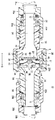
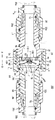
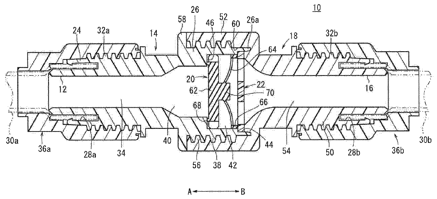
도 1은 본 발명의 제1 실시 형태에 따른 체크 밸브의 전체 단면도이다.
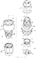
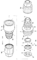
도 2는 도 1의 체크 밸브의 분해 사시도이다.
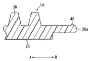
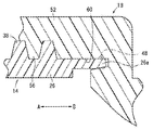
도 3a는 제1 바디에서 제1 연결부의 선단부를 나타낸 확대 단면도이며, 도 3b는 도 3a에 나타낸 제1 연결부가 제2 바디의 제2 연결부와 연결된 상태를 나타낸 확대 단면도이다.
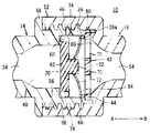
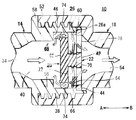
도 4a는 도 1에 나타낸 체크 밸브의 밸브 플러그 근방의 확대 단면도이며, 도 4b는 도 4a에 나타낸 밸브 플러그가 밸브 시트면으로부터 이격된 밸브 열림 상태를 나타낸 전체 단면도이다.
도 5는 본 발명의 제2 실시 형태에 따른 체크 밸브의 전체 단면도이다.
도 6은 도 5에 나타낸 체크 밸브의 분해 사시도이다.
도 7은 본 발명의 제3 실시 형태에 따른 체크 밸브의 전체 단면도이다.1 is an overall sectional view of a check valve according to a first embodiment of the present invention.
Fig. 2 is an exploded perspective view of the check valve of Fig. 1;
FIG. 3A is an enlarged sectional view showing a tip end portion of the first connection portion in the first body, and FIG. 3B is an enlarged sectional view showing a state in which the first connection portion shown in FIG. 3A is connected to the second connection portion of the second body.
Fig. 4A is an enlarged cross-sectional view of the vicinity of the valve plug of the check valve shown in Fig. 1, and Fig. 4B is an overall sectional view showing a state in which the valve plug shown in Fig.
5 is an overall sectional view of a check valve according to a second embodiment of the present invention.
6 is an exploded perspective view of the check valve shown in Fig.
7 is an overall sectional view of a check valve according to a third embodiment of the present invention.
본 발명에 따른 체크 밸브에 관하여 적절한 실시 형태를 들며, 첨부 도면을 참조하면서 이하에 상세히 설명한다.A preferred embodiment of the check valve according to the present invention will be described in detail below with reference to the accompanying drawings.
도 1에 있어서, 참조부호 10은 본 발명의 제1 실시 형태에 따른 체크 밸브를 나타낸다.1,
체크 밸브(10)는, 도 1 및 도 2에 도시된 바와 같이 압력 유체가 공급되는 제1 포트(12)를 가진 제1 바디(14)와, 상기 제1 바디(14)에 접속되어 상기 압력 유체가 배출되는 제2 포트(16)를 가진 제2 바디(18)와, 상기 제1 및 제2 바디(14, 18)의 내부에 설치되는 밸브 플러그(20)와, 상기 밸브 플러그(20)에 근접하여 설치된 스토퍼(22)를 구비한다.The
즉, 제1 바디(14)는 압력 유체가 공급되는 상류측(화살표 A 방향)이 되며, 제2 바디(18)는 상기 제1 바디(14)를 통과한 상기 압력 유체가 배출되는 하류측(화살표 B 방향)이 된다.That is, the
제1 바디(14)는 예를 들면, 수지제 재료로 이루어져 원통 형상으로 형성되고, 일단부에 형성되어 튜브(30a)가 접속되는 제1 커플링부(24)와, 타단부에 형성되어 제2 바디(18)가 연결되는 제1 연결부(26)를 구비한다.The
제1 커플링부(24)의 단부에는, 제1 포트(12)의 외주측에 제1 바디(14)의 축 방향(화살표 A, B 방향)을 따라 튜브홈(28a)이 형성되며, 상기 단부에 삽입 관통된 튜브(30a)의단부가 튜브홈(28a)에 삽입 관통되고 정지된다. 또한, 제1 커플링부(24)의 외주면에는, 튜브홈(28a)에 근접하도록 나사(32a)가 새겨져 있다.A
한편, 제1 커플링부(24)의 내부에는, 제1 포트(12)와 연통하고, 상기 제1 포트(12)와 대략 동일한 직경으로 축 방향(화살표 A, B 방향)을 따라 연장된 제1 유로(34)가 형성된다.On the other hand, inside the
그리고, 제1 커플링부(24)에는, 튜브(30a)가 튜브홈(28a)에 삽입된 상태에서 외주측에 원통 형상의 체결 플러그(36a)가 삽입 관통되어 나사(32a)에 대하여 나사 결합된다. 따라서, 튜브(30a)가 체결 플러그(36a)와 제1 커플링부(24) 사이에 밀착 지지되어 고정된다. 그리고, 튜브(30a)로부터 공급되는 압력 유체가 제1 커플링부(24)의 제1 유로(34)를 통하여 제1 바디(14) 내부로 유통된다.A
제1 연결부(26)는 그 외주면에 나사가 새겨진 수나사부(38)가 형성되며, 후술할 제2 바디(18)의 제2 연결부(52)가 외주측에 나사 결합된다. 수나사부(38)는 예를 들면, 단면이 사다리꼴 형상인 나사산을 가진 사다리꼴 나사(trapezoidal screw)로 형성된다. 한편, 제1 연결부(26)의 내부에는 제1 유로(34)로부터 서서히 직경이 확대되는 제2 유로(40)와, 상기 제2 유로(40)에 대하여 직경이 확대되는 연통 챔버(42)와, 상기 연통 챔버(42)에 대하여 더 직경이 확대된 스토퍼 장착부(44)를 구비한다.The
연통 챔버(42)는 제2 유로(40)에 대하여 단차가 형성된 형상으로 형성되고, 대략 일정 직경으로 제1 바디(14)의 타단부측(화살표 B 방향)을 향하여 소정 길이로 형성된다. 연통 챔버(42)에는 제1 및 제2 유로(34, 40)의 연장 방향과 직교하여 상기 제2 유로(40)와의 경계가 되는 위치에서 링 형상의 밸브 시트면(46, 밸브 시트부)이 형성된다.The
또한, 스토퍼 장착부(44)는, 제1 바디(14)에서 제일 타단부측(화살표 B 방향)에 설치되고, 대략 일정 직경인 링 형상으로 형성된다.The
제1 연결부(26)의 선단부(26a)에는 도 3a 및 도 3b에 나타낸 바와 같이 그 외주면에 링 형상으로 팽창하여 돌출된 돌기부(48)가 형성되며, 제2 바디(18)가 외주측에 장착될 때, 상기 돌기부(48)가 상기 제2 바디(18)에서 제2 연결부(52, 후술할 것임)의 외주면에 슬라이딩하여 접하여 눌러서 밀려지게 된다. 따라서, 제1 바디(14)의 외주면과 제2 바디(18)의 내주면 사이의 기밀이 돌기부(48)에 의하여 확실하게 보호 지지된다(도 3b 참조).3a and 3b, a protruding
제2 바디(18)는 제1 바디(18)와 같이 예를 들면, 수지제 재료로 이루어진 원통 형상으로 형성되고, 일단부에 형성되어 튜브(30b)가 접속되는 제2 커플링부(50)와, 타단부에 형성되어 제1 바디(14)가 연결되는 제2 연결부(52)를 구비한다.The
제2 커플링부(50)의 단부에는, 제2 바디(18)의 축방향(화살표 A, B 방향)을 따라 튜브홈(28b)이 형성되고, 상기 단부에 삽입 관통되는 튜브(30b)의 단부가 튜브홈(28b)에 삽입 관통되어 정지된다. 또한, 제2 커플링부(50)의 외주면에는, 튜브홈(28b)에 근접하도록 나사(32b)가 새겨져 있다.A
한편, 제2 커플링부(50)의 내부에는, 대략 동일한 직경으로 축방향을 따라 소정 길이만큼 연장된 후, 제2 연결부(52)를 향하여 서서히 직경이 확대되는 제3 유로(54)가 형성된다.On the other hand, in the interior of the
그리고, 제2 커플링부(50)에는, 튜브(30b)가 튜브홈(28b)에 삽입 관통된 상태에서 외주측으로 원통 형상인 체결 플러그(36b)가 삽입 관통되고 나사(32b)에 대하여 나사 결합된다. 따라서, 튜브(30b)가 체결 플러그(36b)와 제2 커플링부(50) 사이에 밀착 지지되어 고정된다. 그리고, 제2 바디(18)의 제3 유로(54)를 유통하는 압력 유체가 제2 연결부(52)를 통하여 튜브(30b)로 유통된다.The
제2 연결부(52)는, 그 내주면에 나사가 새겨진 암나사부(56)가 형성되고, 제1 바디(14)의 제1 연결부(26)에 형성되는 암나사부(38)에 나사 결합됨으로써 제1 바디(14)와 제2 바디(18)가 일체로 연결된다. 이때, 제2 바디(18)의 타단부는 제1 바디(14)의 외주측에 형성된 링 형상의 플랜지(58)에 맞닿아 접함으로써 축방향(화살표 A 방향)으로 더욱더 위치 변경이 규제된다. 그리고, 암나사부(56)는 수나사부(38)와 같이 예를 들면, 단면이 사다리꼴 형상인 나사산을 가지는 사다리꼴 나사로 형성된다.The
또한, 제2 연결부(52)에는, 제1 바디(14)와 제2 바디(18)가 연결될 때, 제1 연결부(26)의 선단부(26a)가 밀어 넣어지는 압입홈(60)이 형성되고, 상기 압입홈(60)은 제1 바디(14)로부터 이격하는 방향(화살표 B 방향)을 향하여 끝이 뾰족한 형상이 되도록 형성된다.When the
밸브 플러그(20)는 도 1, 도 2, 도 4a 및 도 4b에 도시된 바와 같이, 예를 들면 수지제 재료로 형성되고, 제1 바디(14)의 연통 챔버(42)에 배치되고 설치된 원반 형상의 본체부(62)와, 상기 본체부(62)의 중앙으로부터 반경 외측 방향을 향하여 직경이 확대되는 스커트부(64, 탄성 반발부)와, 상기 스커트부(64)의 외측 가장자리부에 형성되어 후술할 스토퍼(22)에 맞닿아 접하는 다리부(66, 보호 유지부)로 이루어진다.1, 2, 4A and 4B, the
본체부(62)는, 연통 챔버(42)의 내부에서 축방향(화살표 A, B 방향)을 따라 자유로이 위치 변경 가능하게 설치되고, 그 일단부에는 링 형상으로 돌출된 안착부(68)가 형성되며, 상기 안착부(68)가 연통 챔버(42)의 밸브 시트면(46)에 맞닿아 접한다. 즉, 안착부(68)의 직경은 제2 유로(40)의 직경보다 크게 설정된다.The
또한, 본체부(62)의 타단부에는 중앙에 돌출된 원기둥 형상의 팽출부(70)가 형성되고, 상기 팽출부(70)의 외주면으로부터 스커트부(64)가 반경 외측 방향으로 연장된다.A cylindrical bulged
스커트부(64)는 박막 형상(시트 형상)으로 형성되어 탄성을 가지면서 동심원 상에 중심을 가진 복수(예를 들면, 4개)의 제1 홀 부(72, 홀 부)가 형성된다. 제1 홀 부(72)는 스커트부(64)를 관통하도록 형성되면서 그 둘레 방향을 따라 상호 등간격으로 이격 배치된다.The
그리고, 스커트부(64)는 본체부(62)가 밸브 시트면(46)에 안착되는 밸브 닫힘 상태에서 팽출부(70)와 다리부(66)를 접속하는 단면이 만곡된 형상으로 형성된다.The
한편, 본체부(62)의 외주면은 둘레 방향을 따라 등간격으로 직선 형상으로 절결된 절결부(74)가 복수로 형성되고, 원호 형상으로 형성된 원호부(76)와 절결부(74)가 번갈아가면서 배치된다. 그리고, 본체부(62)는 원호부(76)가 연통 챔버(42)의 내주면과 대략 동일한 직경으로 형성되고, 절결부(74)와 상기 내주면 사이에는 간격이 형성된다.On the other hand, the outer circumferential surface of the
다리부(66)는 링 형상으로 밸브 플러그(20)의 축방향을 따라 소정 높이로 형성되며, 그 외주면이 연통 챔버(42)의 내주면에 맞닿아 접하면서 단부가 스토퍼(22)의 끝면에 맞닿아 접한다. 그리고, 밸브 플러그(20)에서는 스커트부(64)가 다리부(66)를 지지점으로 하여 본체부(62)를 상기 다리부(66)로부터 이격하는 방향(화살표 A 방향)으로 밀어붙이는 탄성 반발력을 가지며, 상기 본체부(62)는 평소 연통 챔버(42)의 밸브 시트면(46)에 맞닿아 접하도록 밀어눌려진다. 즉, 스커트부(64)는 본체부(62)를 밸브 시트면(46)에 안착시키는 방향(화살표 A 방향)으로 밀어붙이는 탄성 반발부로 기능한다.The
스토퍼(22)는 예를 들면, 수지제 재료로 이루어져 소정 두께를 가지고 원반 형상으로 형성되며, 동심원 상에 중심을 가지는 복수(예를 들면, 4개)의 제2 홀부(78)가 형성된다. 제2 홀부(78)는 스토퍼(22)를 관통하도록 형성되면서 그 둘레 방향을 따라 상호 등간격으로 이격되게 배치된다.The
그리고, 스토퍼(22)는 제1 바디(14)의 스토퍼 장착부(44)에 장착되고, 상기 스토퍼 장착부(44)의 끝면에 정지됨으로써 상기 제1 바디(14)에서 축방향으로의 위치 결정이 되도록 하면서 상기 제1 바디(14)에 대하여 제2 바디(18)를 연결할 때, 제2 바디(18)의 단차 형성부(80)에 맞닿아 접함으로써 상기 스토퍼 장착부(44) 사이에 밀착 지지되어 고정된다.The
스토퍼(22)에는 복수의 제2 홀부(78)가 관통되어 있으므로, 연통 챔버(42)와 제3 유로(54)가 평소 상기 제2 홀부(78)를 통하여 연통되는 상태가 된다.The
본 발명의 제1 실시 형태에 따른 체크 밸브(10)는 기본적으로는 이상과 같이 구성되는 것이며, 다음에 그 동작 및 작용 효과에 관하여 설명한다. 그리고, 체크 밸브(10)를 구성하는 제1 바디(14)에는 도시하지 않은 압력 유체 공급원에 대하여 접속되는 튜브(30a)가 접속되고, 제2 바디(18)에는 압력 유체의 공급 작용하에서 구동 가능한 유체압 기기(미도시)에 접속되는 튜브(30b)가 미리 접속된 상태로 해 둔다.The
우선, 도 1 및 도 4a에 도시된 밸브 플러그(20)의 안착부(68)가 밸브 시트면(46)에 대하여 안착되고, 제1 바디(14)의 제1 및 제2 유로(34, 40)와, 제2 바디(18)의 제3 유로(54)의 연통이 차단되는 밸브 닫힘 상태에서 상류측이 되는 튜브(30a)로부터 제1 바디(14)에 대하여 압력 유체가 공급되며, 상기 압력 유체가 제1 유로(34), 제2 유로(40)로 유통한 후, 밸브 플러그(20)의 본체부(62)를 제2 바디(18)측(화살표 B 방향)을 향하여 밀어 누른다. 따라서, 밸브 플러그(20)가 스커트부(64)의 탄성 반발력에 저항하여 스토퍼(22)측(화살표 B 방향)으로 이동하고, 안착부(68)가 밸브 시트면(46)으로부터 이격된다. 따라서, 압력 유체가 제2 유로(40)로부터 밸브(20)의 절결부(74)와 연통 챔버(42) 사이의 간격을 통하여 상기 연통 챔버(42)의 내부로 유입된다. 이때, 밸브 플러그(20)는 도 4b에 도시된 바와 같이 팽출부(70)의 끝면이 스토퍼(22)에 맞닿아 접함으로써 위치 변경이 규제된다.First, the seating
그리고, 압력 유체는 연통 챔버(42)의 내부로부터 스커트부(64)의 제1 홀부(72), 스토퍼(22)의 제2 홀부(78)를 통하여 제2 바디(18)의 제3 유로(54)로 유통된 후, 제2 커플링부(50)에 접속된 튜브(30b)를 통하여 도시하지 않은 유체압 기기로 공급된다.The pressure fluid flows from the inside of the
다음으로, 몇가지의 이유로 제2 바디(18)로부터 제1 바디(14)측(화살표 A 방향)으로 압력 유체가 역류하려 하는 경우에 관하여 설명한다. 그리고, 이 경우, 제1 바디(14)의 제1 및 제2 유로(34, 40)에는, 압력 유체가 공급되지 않고 대기 개방 상태에 있는 것으로 한다.Next, a description will be given of a case in which the pressure fluid attempts to flow back from the
예를 들면, 하류측의 튜브(30b)로부터 제2 바디(18)의 제3 유로(54)로 압력 유체가 공급되면, 상기 압력 유체는, 스토퍼(22)의 제2 홀부(78), 밸브 플러그(20)에서 스커트부(64)의 제1 홀부(72)를 통하여 연통 챔버(42)로 유입된다.For example, when the pressure fluid is supplied from the
이때, 밸브 플러그(20)는 스커트부(64)의 탄성 반발력에 의하여 본체부(62)가 제1 바디(14)측(화살표 A 방향)으로 밀어 눌려지면서 압력 유체에 의하여도 같은 형태로 제1 바디(14)측(화살표 A 방향)으로 밀어 눌려진다. 따라서, 밸브 플러그(20)의 안착부(68)가 밸브 시트면(46)에 대하여 안착되고, 연통 챔버(42)와 제1 바디(14)의 제2 유로(40)와의 연통이 차단된 밸브 닫힘 상태로 유지된다(도 1, 도 4a 참조).At this time, the
그 결과, 제2 바디(18)로부터 압력 유체가 공급되는 경우에도, 밸브 플러그(20)가 스커트부(64)의 탄성 반발력에 의하여 확실하게 밸브 닫힘 상태가 되므로, 상기 압력 유체가 제1 바디(14)의 제1 및 제2 유로(3, 40)로 유통하는 것이 저지된다.As a result, even when the pressure fluid is supplied from the
이상과 같이 제1 실시 형태에서는 밸브 플러그(20)를 안착시킬 때 밀어 누르는 힘을 밀어 붙이기 위하여 수지제로 압축 코일 스프링으로 이루어진 스프링을 설치하는 대신에, 수지제 재료로 이루어져 탄성 반발력을 지닌 스커트부(64)를 밸브 플러그(20)의 본체부(62)에 대하여 일체로 형성함으로써 상기 스커트부(64)의 탄성 반발력을 본체부(62)에 대하여 확실하고 적절하게 부여하고, 상기 본체부(62)의 안착부(68)를 밸브 시트면(46)에 대하여 안착시키는 것이 가능하다. 그 결과, 수지제의 스프링을 형성하고, 그 탄성 반발력을 이용하여 밸브 플러그(20)를 안착시키는 종래의 체크 밸브와 비교하여 그 구성을 간소화할 수 있으므로, 소형화를 도모할 수 있음과 동시에 제조 비용을 저감할 수 있게 된다.As described above, in the first embodiment, instead of providing a spring made of a resin-made compression coil spring for pushing a pushing-pushing force when the
또한, 스커트부(64)에는 복수의 제1 홀부(72)가 형성되어 있으므로, 밸브 플러그(20)가 밸브 시트면(46)으로부터 이격하여 밸브 열림 상태가 되더라도 압력 유체가 상기 제1 홀부(72)를 통하여 하류측으로 확실하게 유통할 수 있으므로, 종래 기술에 따른 체크 밸브와 같이 상기 압력 유체의 유량이 저하되는 일이 없이 상기 압력 유체를 소망하는 유량으로 원활하게 유통시킬 수 있다.Since the plurality of
그리고, 제1 바디(14)의 제1 연결부(26)에 형성된 수나사부(38)와, 제2 바디(18)의 제2 연결부(52)에 형성된 암나사부(56)가 각각 사다리꼴 형상으로 형성되므로, 상기 제1 연결부(26)와 제2 연결부(52)를 나사 결합시켜 연결할 때, 그 연결을 확실하고 견고하게 할 수 있으면서도 상기 수나사부(38)와 암나사부(56)의 풀림을 억제할 수 있다.The
또한, 제1 바디(14)에서 제1 연결부(26)의 선단부(26a)에 링 형상으로 팽창하여 돌출된 돌기부(48)를 외주면에 형성함과 동시에 제2 바디(18)의 제2 연결부(52)에는 상기 선단부(26a)가 밀어 넣어지는 압입홈(60)을 형성함으로써 상기 제1 바디(14)와 제2 바디(18)를 나사 결합시켜 연결할 때 돌기부(48)가 제2 연결부(52)의 내주면에 슬라이딩하여 접하고 눌러 밀려지고, 한편 제1 연결부(26)의 선단부(26a)가 압입홈(60)에 밀어 넣어져 눌러 밀려진다. 따라서, 제1 연결부(26)와 제2 연결부(52)를 한층 더욱 확실하고 견고하게 연결할 수 있음과 동시에 상기 제1 연결부(26)와 제2 연결부(52) 사이의 밀폐가 이루어지고, 제1 바디(14)와 제2 바디(18)의 연결 부위로부터 압력 유체가 외부로 누출되는 것을 방지할 수 있다.The
그리고, 위에서 설명한 제1 실시 형태에서는 제1 바디(14)의 제1 연결부(26) 선단부(26a)가 제2 바디(18)의 압입홈(60)에 밀어 넣어지는 구성으로 되어 있으나, 이것에 한정되는 것은 아니며, 예를 들면 상기 제1 연결부(26)에 압입홈을 형성하고, 상기 제2 바디(18)에서 제2 연결부(52)의 선단부에 돌기부를 형성함으로써 상기 선단부를 상기 압입홈에 밀어 넣어 밀폐를 행하도록 하여도 좋다.In the first embodiment described above, the
또한, 탄성 반발부로서 기능하는 스커트부(64)를 밸브 플러그(20)와 일체적으로 형성함으로써 제1 및 제2 바디(14, 18)에 대하여 상기 밸브 플러그(20)를 조립하는 것과 동시에 상기 스커트부(64, 탄성 반발부)를 조립하는 것이 가능하게 되며, 조립 공정 수를 저감할 수 있으면서 부품 수를 줄이는 것도 가능하게 된다.The
다음으로, 제2 실시 형태에 따른 체크 밸브(100)를 도 5 및 도 6에 나타낸다. 그리고, 위에서 설명한 제1 실시 형태에 따른 체크 밸브(10)와 동일한 구성요소에는 동일한 참조 부호를 붙여 그 상세한 설명을 생략한다.Next, the
제2의 실시 형태에 따른 체크 밸브(100)에는 도 5 및 도 6에 도시된 바와 같이 원반 형상의 본체부(102)와, 상기 본체부(102)와는 별도로 형성되어 상기 본체부(102)에 연결되는 탄성 반발부(104)로 이루어진 밸브 플러그(106)를 구성하는 점에서 제1 실시 형태에 따른 체크 밸브(10)와 서로 다르다.5 and 6, the
체크 밸브(100)를 구성하는 밸브 플러그(106)는 링 형상의 안착부(68)를 가지는 본체부(102)와, 상기 본체부(102)의 팽출부(108)에 형성된 끼움결합홀(110)에 끼움 결합되는 탄성 반발부(104)를 구비한다. 상기 탄성 반발부(104)는 상기 탄성 반발부(104)의 중앙에 형성된 끼움결합홀(110)에 끼움 결합되는 끼움결합부(112)와, 상기 끼움결합부(112)의 외주면으로부터 반경 외측 방향으로 직경이 확장되는 스커트부(64)와, 상기 스커트부(64)의 외주부에 형성되는 다리부(66)를 구비한다.The
끼움결합홀(110)은 팽출부(108)의 끝면으로부터 소정 깊이로 형성되고, 상기 끼움결합홀(110)에 대하여 대략 동일 직경 또는 약간 큰 직경으로 형성되는 축 형상의 끼움결합부(112)가 삽입됨으로써 본체부(102)에 대하여 탄성 반발부(104)가 일체로 연결된다.The fitting
그리고, 제1 바디(14)에 공급되는 압력 유체에 의하여 밸브 플러그(106)의 본체부(102)가 제2 바디(18)측(화살표 B 방향)으로 밀어 눌려지고, 상기 본체부(102)가 탄성 반발부(104)의 탄성 반발력에 저항하여 밸브 시트면(46)으로부터 이격하는 방향으로 이동함으로써 제1 바디(14)의 제1 및 제2 유로(34, 40)와 제2 바디(18)의 제3 유로(54)가 연통 챔버(42)를 통하여 연통된다.The
이상과 같이 제2 실시 형태에서는 밸브 플러그(106)를 본체부(102)와 탄성 반발부(104)로부터 각각 별개로 형성하여 상호 조립되는 구성으로 함으로써 상기 본체부(102) 및 탄성 반발부(104)를 일체로 형성하는 경우에 비하여 그 제조가 용이하게 되며, 이에 따라 제조 비용 저감을 도모할 수 있게 되며, 저렴한 체크 밸브(100)를 제조할 수 있다.As described above, according to the second embodiment, the
또한, 밸브 플러그(106)에 있어서 본체부(102)와 탄성 반발부(104)를 별개 구성으로 함으로써 상기 본체부(102)와 탄성 반발부(104)를 다른 재질로 형성할 수 있으므로, 예를 들면 유통하는 압력 유체의 종류에 대응하여 재질을 변경하는 것이 쉬워진다.Since the
다음으로, 제3 실시 형태에 따른 체크 밸브(150)를 도 7에 나타낸다. 그리고, 위에서 설명한 제2 실시 형태에 따른 체크 밸브(100)와 동일 구성 요소에는 동일 참조부호를 붙이며, 그 상세한 설명을 생략한다.Next, a
제3 실시 형태에 따른 체크 밸브(150)에서는 도 7에 도시된 바와 같이 제1 바디(14)의 제1 연결부(26)와, 제2 바디(154)의 제2 연결부(156)의 연결을 행할 때, 서로 나사 결합시키는 것 뿐만 아니라, 풀림 방지기구(152)를 이용하여 연결하는 점에서 제2 실시 형태에 따른 체크 밸브(100)와 서로 다르다.7, the
체크 밸브(150)에 사용되는 풀림 방지기구(152)는 제2 바디(154)의 제2 연결부(156)의 외주면으로부터 내주측을 향하여 관통된 관통공(158)과, 상기 관통공(158)에 삽입되어 상기 제1 바디(14)의 수나사부(38)에 결합되는 멈춤핀(160)과, 상기 관통공(158)에 밀어 넣어져 상기 멈춤핀(160)의 탈락을 방지하는 밀봉 볼(162)을 포함한다.The unlocking
관통공(158)은 제1 바디(14)와 제2 바디(154)를 연결할 때, 제1 연결부(26)에서 수나사부(38)의 골 부분에 대면하는 위치에 형성되고, 상기 관통공(158)에는 제2 바디(154)의 외주측으로부터 멈춤핀(160)이 삽입됨과 동시에 상기 멈춤핀(160)의 외주측에 밀봉 볼(162)이 압입된다.The through
멈춤핀(160)은 예를 들면, 금속제 재료로 이루어져 대략 일정 직경을 가진 축 형상으로 형성되고, 그 선단은 수나사부(38)의 골 부분에 대응하는 형상으로 형성된다. 밀봉 볼(162)은 예를 들면, 수지제 재료로 형성되고, 관통공(158)의 내주 직경에 대하여 약간 큰 직경으로 형성된다.The
그리고, 제1 바디(14)의 제1 연결부(26)와 제2 바디(154)의 제2 연결부(156)를 상호 나사 결합시켜 연결한 후, 상기 제2 연결부(156)의 외주측으로부터 관통공(158)에 대하여 멈춤핀(160)을 삽입하고, 그 선단을 제1 바디(14)에 있어서 수나사부(38)에 결합시키는 것과 동시에 상기 관통공(158)에 대하여 밀봉 볼(162)을 밀어 넣는다. 그리고, 밀봉 볼(162)은 관통공(158)의 끝면으로부터 돌출하는 일이 없도록 삽입된다.The
이와 같이 제3 실시 형태에서는 제1 연결부(26)의 수나사부(38)와 제2 연결부(156)의 암나사부(56)를 나사 결합시킴으로써 제1 바디(14)와 제2 바디(154)를 연결한 후, 상기 제2 연결부(156)에 형성된 관통공(158)에 멈춤핀(160)을 삽입하여 제1 연결부(126)에 대하여 결합시킴으로써 상기 제1 연결부(26)와 제2 연결부9156)의 축방향(화살표 A, B 방향)으로의 상대적인 위치 변경을 저지할 수 있다. 그 결과, 예를 들면 체크 밸브(150)를 진동 등이 발생하는 환경에서 사용하는 경우에도 제1 바디(14)와 제2 바디(154)의 연결이 풀리는 것이 풀림 방지기구(152)에 의하여 확실하게 방지되며, 상기 체크 밸브(150)를 안심하고 사용할 수 있다.As described above, in the third embodiment, the
또한, 관통공(158)에서 멈춤핀(160)의 외주측에 밀봉 볼(162)을 밀어 넣음으로써 상기 관통공(158)에서 멈춤핀(160)의 위치 변경이 규제되므로, 상기 멈춤핀(160)에 의한 제1 바디(14)와 제2 바디(154)의 멈춤 상태가 확실하게 유지될 수 있음과 동시에 상기 멈춤핀(160)이 관통공(158)으로부터 탈락되는 것도 확실하게 방지할 수 있다. 그리고, 관통공(158)에 밀봉 볼(162)을 밀어 넣는 간단한 작업으로 확실하게 멈춤핀(160)의 이동, 탈락을 방지할 수 있으므로 적합한다.Since the position of the
그리고, 본 발명에 따른 체크 밸브는, 위에서 설명한 실시 형태에 한정되지 않으며, 본 발명의 요지를 일탈하는 일이 없으며, 다양한 구성을 채택하여 얻어질 수 있음은 물론이다.It is needless to say that the check valve according to the present invention is not limited to the above-described embodiment, and can be obtained by adopting various configurations without departing from the gist of the present invention.
10, 100, 150...체크 밸브
14...제1 바디
18, 154...제2 바디
20, 106...밸브 플러그
22...스토퍼
24...제1 커플링부
26...제1 연결부
34...제1 유로
38...수나사부
40...제2 유로
42...연통 챔버
44...스토퍼 장착부
46...밸브 시트면
50...제2 커플링부
52, 156...제2 연결부
54...제3 유로
56...암나사부
62, 102...본체부
64...스커트부
66...다리부
68...안착부
72...제1 홀부
78...제2 홀부
104...탄성 반발부
110...끼움결합홀
112...끼움결합부
152...풀림 방지기구
158...관통공
160...멈춤핀
162...밀봉 볼10, 100, 150 ... Check valve
14 ... first body
18, 154 ... second body
20, 106 ... valve plug
22 ... Stopper
24 ... first coupling portion
26 ... first connection portion
34 ... First Euro
38 ... male threads
40 ... second euro
42 ... communication chamber
44 ... stopper mount
46 ... valve seat face
50 ... second coupling portion
52, 156 ... second connection portion
54 ... 3rd Euro
56 ... female thread part
62, 102,
64 ... skirt part
66 ... leg
68 ... seat portion
72 ... first hollow portion
78 ... second hollow portion
104 ... elastic restoring portion
110 ... fitting hole
112 ... fitting portion
152 ... anti-loosening mechanism
158 ... through hole
160 ... stop pin
162 ... sealing ball
Claims (11)
상기 제1 바디(14)에 연결되고, 상기 압력 유체가 배출되는 제2 포트(16)를 가지는 제2 바디(18)와,
상기 제1 및 제2 바디(14, 18)의 내부에 설치되고, 상기 압력 유체가 유통되는 유로의 연통 상태를 절환하는 밸브 플러그(20)와,
상기 제1 바디(14)에 형성된 밸브 시트부(46)측을 향하여 상기 밸브 플러그(20)를 밀어 붙이고, 상기 밸브 플러그(20)를 상기 밸브 시트부(46)에 안착시키는 탄성반발수단을 구비하며,
상기 탄성반발수단은, 상기 제2 바디(18)에 보호 유지되는 보호 유지부(66)와, 상기 보호 유지부(66)에 접합되고 상기 밸브 플러그(20)를 상기 제2 바디(18)로부터 이격되는 방향을 향하여 밀어 붙이는 시트 형상의 탄성반발부(64)를 가지며, 상기 탄성반발부(64)에는, 상기 압력 유체가 유통하는 홀 부(72)가 형성되며,
상기 보호 유지부(66)는 링 형상으로 밸브 플러그(20)의 축방향을 따라 소정 높이로 형성되며, 상기 제1 바디(14)에 구비된 제1 연결부(26)의 내부에 형성된 연통 챔버(42)의 내주면에 상기 보호 유지부(66)의 외주면이 맞닿아 접하면서 단부가 스토퍼(22)의 끝면에 맞닿아 접하는 것을 특징으로 하는 체크 밸브.A first body (14) having a first port (12) through which pressure fluid is supplied,
A second body 18 connected to the first body 14 and having a second port 16 through which the pressure fluid is discharged,
A valve plug (20) installed inside the first and second bodies (14, 18) for switching the communication state of the flow path through which the pressure fluid flows,
And elastic resilience means for pushing the valve plug 20 toward the valve seat portion 46 formed on the first body 14 and seating the valve plug 20 on the valve seat portion 46 In addition,
The elastic resilient means includes a protection holding portion 66 which is protected by the second body 18 and a protection holding portion 66 which is connected to the protection holding portion 66 and which extends from the second body 18 Like elastic resilient part 64 which is pressed toward the direction in which the pressure fluid flows, and a hole part 72 through which the pressure fluid flows is formed in the elastic resilient part 64,
The protection holding portion 66 is formed in a ring shape at a predetermined height along the axial direction of the valve plug 20 and is formed in a communication chamber (not shown) formed in the first connection portion 26 provided in the first body 14 42) is in contact with the outer circumferential surface of the protective holding portion (66) and abuts against the end surface of the stopper (22) so that the end portion abuts against the end surface of the stopper (22).
상기 탄성반발수단은, 상기 밸브 플러그(20)와 일체로 형성되는 것을 특징으로 하는 체크 밸브.The method according to claim 1,
Wherein the resilient repulsion means is formed integrally with the valve plug (20).
상기 탄성반발수단은, 상기 밸브 플러그(20)와 별도로 상기 밸브 플러그(20)에 대하여 자유로이 탈착 가능하게 설치되는 것을 특징으로 하는 체크 밸브.The method according to claim 1,
Wherein the elastic resilient means is freely detachably attached to the valve plug (20) separately from the valve plug (20).
상기 제1 및 제2 바디(14, 18)와, 상기 밸브 플러그(20) 및 상기 탄성반발부(64)는, 각각 수지제 재료로 형성되는 것을 특징으로 하는 체크 밸브.The method according to claim 1,
Wherein the first and second bodies (14, 18), the valve plug (20), and the resilient repulsion portion (64) are each made of a resin material.
상기 제1 바디(14)와, 상기 제2 바디(18)는, 각각에 형성된 나사부(38, 56)를 상호 나사 결합시킴으로써 연결되고, 상기 나사부(38, 56)는 사다리꼴 나사(trapezoidal screw)로 형성되는 것을 특징으로 하는 체크 밸브.The method according to claim 1,
The first body 14 and the second body 18 are connected to each other by threadedly coupling the threaded portions 38 and 56 formed thereon and the threaded portions 38 and 56 are connected to each other by a trapezoidal screw And the check valve is formed.
상기 제1 바디(14)와 상기 제2 바디(18)의 연결 부위에는, 상기 제1 바디(14)와 제2 바디(18)의 나사 결합 상태가 풀리는 것을 방지하는 풀림 방지기구(152)가 형성되는 것을 특징으로 하는 체크 밸브.The method according to claim 1,
A loosening preventing mechanism 152 is provided at a connecting portion between the first body 14 and the second body 18 to prevent the first body 14 and the second body 18 from being unscrewed And the check valve is formed.
상기 풀림 방지기구(152)는, 상기 제1 및 제2 바디(14, 18)의 축선과 직교 방향으로 삽입되어 결합되는 멈춤핀(160)을 가지는 것을 특징으로 하는 체크 밸브.The method of claim 6,
Wherein the unlocking mechanism (152) has a detent pin (160) inserted and coupled in a direction orthogonal to an axis of the first and second bodies (14,18).
상기 제1 바디 또는 제2 바디(14, 18) 중 어느 일측의 단부 외주면에는, 반경 외측 방향으로 돌출된 돌기부(48)가 형성되고, 상기 돌기부(48)를 가진 상기 제1 바디(14) 또는 제2 바디(18) 중 어느 일측과 반대가 되는 상기 제2 바디(18) 또는 제1 바디(14)에는, 상기 단부가 밀어넣어지는 홈부(60)가 형성되는 것을 특징으로 하는 체크 밸브.The method according to claim 1,
A protrusion 48 protruding in a radially outward direction is formed on an outer circumferential surface of an end of either one of the first body 14 or the second body 14 and the first body 14 or the second body 14 having the protrusion 48 Wherein the second body (18) or the first body (14) opposite to any one of the second bodies (18) has a groove portion (60) into which the end portion is pushed.
상기 탄성 반발부(64)는, 단면이 만곡 형상으로 형성되는 것을 특징으로 하는 체크 밸브.The method according to claim 1,
Wherein the resilient repulsion portion (64) has a curved cross section.
상기 밸브 플러그(20)는, 상기 밸브 시트부(46)에 안착되는 안착부(68)를 가지며, 상기 안착부(68)보다 외주측이 되는 외주면에는 상기 외주면이 절결된 절결부(74)가 형성되는 것을 특징으로 하는 체크 밸브.The method according to claim 1,
The valve plug 20 has a seating portion 68 that is seated on the valve seat portion 46. A notched portion 74 is formed on the outer peripheral surface of the valve plug 20 which is closer to the outer peripheral side than the seating portion 68, And the check valve is formed.
상기 스토퍼(22)는, 상기 제1 바디(14)의 스토퍼 장착부(44)에 장착되고, 상기 스토퍼 장착부(44)의 끝면에 정지됨으로써, 상기 제1 바디(14)에 있어서 축선 방향으로의 위치 결정이 이루어짐과 동시에, 상기 제1 바디(14)에 대하여 상기 제2 바디(18)를 연결할 때, 상기 제2 바디(18)의 단차 형성부(80)에 맞닿아 접함으로써 상기 스토퍼 장착부(44) 사이에 밀착 지지되어 고정되는 것을 특징으로 하는 체크 밸브.The method according to claim 1,
The stopper 22 is mounted on the stopper mounting portion 44 of the first body 14 and stops at the end face of the stopper mounting portion 44 so that the position of the first body 14 in the axial direction When the second body 18 is connected to the first body 14 by abutment against the step forming portion 80 of the second body 18, the stopper mounting portion 44 And is fixedly supported and fixed between the check valve and the check valve.
Applications Claiming Priority (2)
| Application Number | Priority Date | Filing Date | Title |
|---|---|---|---|
| JPJP-P-2011-242731 | 2011-11-04 | ||
| JP2011242731A JP5561492B2 (en) | 2011-11-04 | 2011-11-04 | Check valve |
Publications (2)
| Publication Number | Publication Date |
|---|---|
| KR20130049738A KR20130049738A (en) | 2013-05-14 |
| KR101485143B1 true KR101485143B1 (en) | 2015-01-22 |
Family
ID=48129055
Family Applications (1)
| Application Number | Title | Priority Date | Filing Date |
|---|---|---|---|
| KR1020120123333A Active KR101485143B1 (en) | 2011-11-04 | 2012-11-02 | Check valve |
Country Status (7)
| Country | Link |
|---|---|
| US (1) | US9046182B2 (en) |
| JP (1) | JP5561492B2 (en) |
| KR (1) | KR101485143B1 (en) |
| CN (1) | CN103090059B (en) |
| DE (1) | DE102012110489B4 (en) |
| FR (1) | FR2982337B1 (en) |
| TW (1) | TWI481790B (en) |
Families Citing this family (18)
| Publication number | Priority date | Publication date | Assignee | Title |
|---|---|---|---|---|
| WO2014204586A1 (en) * | 2013-06-17 | 2014-12-24 | Illinois Tool Works Inc. | Bidirectional valve with improved threshold pressure accuracy |
| CN103438253B (en) * | 2013-08-15 | 2016-06-01 | 奇瑞汽车股份有限公司 | A kind of self-locking type one-way valve |
| JP5984094B2 (en) * | 2013-09-24 | 2016-09-06 | Smc株式会社 | Ultrasonic flow meter |
| CN104696638A (en) * | 2013-12-09 | 2015-06-10 | 江苏江淮动力股份有限公司 | Unidirectional fixed throttle pipe joint |
| WO2016153004A1 (en) * | 2015-03-25 | 2016-09-29 | 株式会社タクミナ | Non-return valve and valve body |
| CN107466252B (en) * | 2016-04-29 | 2019-05-31 | 深圳市大疆创新科技有限公司 | Pressure accumulating sealing mechanism and nozzle device |
| CN105782524B (en) * | 2016-05-03 | 2018-11-20 | 孙留红 | pressure limiting valve |
| KR20180034155A (en) * | 2016-09-27 | 2018-04-04 | 주식회사 대우전자 | Washing machine |
| KR20180034145A (en) * | 2016-09-27 | 2018-04-04 | 주식회사 대우전자 | Washing machine |
| KR20180034153A (en) * | 2016-09-27 | 2018-04-04 | 주식회사 대우전자 | Washing machine |
| KR102052817B1 (en) * | 2018-03-21 | 2019-12-05 | 서천석 | Backflow prevention unit for shower hose |
| FR3080165B1 (en) * | 2018-04-12 | 2020-05-01 | Staubli Faverges | FITTING ELEMENT AND FITTING COMPRISING SUCH A FITTING ELEMENT |
| DE102018009963A1 (en) * | 2018-12-21 | 2020-06-25 | Aventics Gmbh | Sealing membrane and check valve with sealing membrane for fluid power applications |
| CN109869512B (en) * | 2019-04-17 | 2024-01-05 | 中山大洋电机股份有限公司 | Compact check valve and fuel cell using same |
| CN110259995A (en) * | 2019-07-24 | 2019-09-20 | 清华大学 | Check valve and hydraulic system |
| EP4214432A4 (en) * | 2020-09-17 | 2024-05-29 | Fluid Handling LLC | CHECK VALVE ASSEMBLY HAVING A CHECK VALVE ASSEMBLY JOINT FORMED BETWEEN A CHECK VALVE HOUSING, A CHECK VALVE BODY ADAPTER, AND A LOCKING RING |
| EP4522904A1 (en) * | 2022-05-09 | 2025-03-19 | PepsiCo, Inc. | Beverage dispenser water supply connector |
| CN118023004B (en) * | 2024-04-12 | 2024-06-28 | 通渭县食品药品检验检测中心 | Nozzle device for mixing food and medicine |
Citations (2)
| Publication number | Priority date | Publication date | Assignee | Title |
|---|---|---|---|---|
| JPS6034157U (en) * | 1983-08-17 | 1985-03-08 | 日信工業株式会社 | Check valve device |
| JPH0165990U (en) * | 1987-10-22 | 1989-04-27 |
Family Cites Families (22)
| Publication number | Priority date | Publication date | Assignee | Title |
|---|---|---|---|---|
| US3372707A (en) | 1965-04-12 | 1968-03-12 | Honeywell Inc | Pressure regulator valve |
| US3465786A (en) | 1966-09-08 | 1969-09-09 | Gar Wood Ind Inc | Vacuum check valve |
| DE1550614A1 (en) * | 1966-12-15 | 1969-11-06 | Westinghouse Bremsen Und Appba | Closing device for pneumatic check valves |
| DE2521878A1 (en) * | 1975-05-16 | 1976-11-25 | Daimler Benz Ag | Non-return valve with moulded rubber valve head - has plate spring clamped between two halves of housing |
| JPS5881275A (en) * | 1981-11-11 | 1983-05-16 | Hitachi Ltd | Valve device for reciprocating compressor |
| JPS6034157A (en) | 1983-08-02 | 1985-02-21 | Masaharu Omiya | Preparation of raw material of pasty food composed mainly of salmon roe |
| DE3329652A1 (en) * | 1983-08-17 | 1985-02-28 | Steuerungstechnik Staiger GmbH & Co Produktions-Vertriebs-KG, 7121 Erligheim | Non-return valve |
| JPH0647093Y2 (en) * | 1991-10-09 | 1994-11-30 | ショーボンド建設株式会社 | Check valve for adhesive injection device |
| JP3302781B2 (en) * | 1993-06-18 | 2002-07-15 | 清原 まさ子 | Line check valve |
| JPH0754658A (en) * | 1993-08-06 | 1995-02-28 | Yamato Seisakusho:Kk | Check valve for internal combustion engine |
| DK0955491T3 (en) | 1997-12-09 | 2001-01-29 | Sporting S A | Universal valve |
| DE69906740T2 (en) * | 1998-07-09 | 2004-01-29 | Parker Hannifin Corp | CHECK VALVE |
| JP3369523B2 (en) | 1999-12-27 | 2003-01-20 | 日本ピラー工業株式会社 | Check valve |
| JP4632162B2 (en) * | 2000-03-03 | 2011-02-16 | Smc株式会社 | Structure of fluid passage outlet of fluid equipment |
| JP2003028352A (en) * | 2001-07-17 | 2003-01-29 | Neriki:Kk | Container valve |
| US6547108B2 (en) * | 2001-08-31 | 2003-04-15 | Sonoco Development, Inc. | Pressure-activated flexible valve |
| JP3780224B2 (en) | 2002-04-30 | 2006-05-31 | Smc株式会社 | Check valve device |
| EP1748235A1 (en) | 2005-07-27 | 2007-01-31 | Pres-Block S.P.A. | Improved valve assembly |
| DE102007016898A1 (en) | 2007-04-10 | 2008-10-16 | Continental Automotive Gmbh | Valve e.g. check valve, for e.g. high-pressure pump in fuel supply system of motor vehicle, has valve body locking sealing seat, spring device pretensioning valve body against sealing seat, and spring washer formed by two concentric rings |
| JP2009138888A (en) | 2007-12-10 | 2009-06-25 | Miura Co Ltd | Check valve |
| US7721763B2 (en) * | 2008-01-08 | 2010-05-25 | Pradip Choksi | Adjustable pressure relief valve |
| JP5150556B2 (en) * | 2009-04-28 | 2013-02-20 | 積水化学工業株式会社 | Ball valve |
-
2011
- 2011-11-04 JP JP2011242731A patent/JP5561492B2/en not_active Expired - Fee Related
-
2012
- 2012-10-09 TW TW101137231A patent/TWI481790B/en active
- 2012-11-02 KR KR1020120123333A patent/KR101485143B1/en active Active
- 2012-11-02 US US13/667,663 patent/US9046182B2/en active Active
- 2012-11-02 DE DE102012110489.1A patent/DE102012110489B4/en active Active
- 2012-11-02 FR FR1260450A patent/FR2982337B1/en active Active
- 2012-11-02 CN CN201210435090.8A patent/CN103090059B/en active Active
Patent Citations (2)
| Publication number | Priority date | Publication date | Assignee | Title |
|---|---|---|---|---|
| JPS6034157U (en) * | 1983-08-17 | 1985-03-08 | 日信工業株式会社 | Check valve device |
| JPH0165990U (en) * | 1987-10-22 | 1989-04-27 |
Also Published As
| Publication number | Publication date |
|---|---|
| US9046182B2 (en) | 2015-06-02 |
| KR20130049738A (en) | 2013-05-14 |
| CN103090059B (en) | 2015-08-19 |
| FR2982337B1 (en) | 2015-07-03 |
| JP5561492B2 (en) | 2014-07-30 |
| DE102012110489B4 (en) | 2016-12-15 |
| JP2013096553A (en) | 2013-05-20 |
| CN103090059A (en) | 2013-05-08 |
| TWI481790B (en) | 2015-04-21 |
| FR2982337A1 (en) | 2013-05-10 |
| TW201331495A (en) | 2013-08-01 |
| DE102012110489A1 (en) | 2013-05-08 |
| US20130112302A1 (en) | 2013-05-09 |
Similar Documents
| Publication | Publication Date | Title |
|---|---|---|
| KR101485143B1 (en) | Check valve | |
| CA2582499C (en) | Dome check valve | |
| US9638345B2 (en) | Valve apparatus | |
| CA2758594C (en) | Biased blind side temporary fasteners, systems and methods | |
| JP3984524B2 (en) | Connector with built-in valve | |
| JP4596281B2 (en) | Pipe fitting | |
| JP2004257521A (en) | Valve | |
| JP2008075715A (en) | Pipe fitting | |
| JP4552228B2 (en) | Connector with built-in valve | |
| US8944097B2 (en) | Decompression valve | |
| US7703744B2 (en) | Core push-in seal | |
| JP4792231B2 (en) | Connector with built-in valve | |
| JP2005163836A (en) | Connector with built-in valve | |
| JP4798510B2 (en) | Spring structure used in fluid pressure equipment | |
| JP7175497B2 (en) | Check valve | |
| JP6360773B2 (en) | Gas tap with fuse | |
| US7021331B2 (en) | Check valve with locked restraint mechanism | |
| US12036428B2 (en) | Positive pressure exhale valve for a breathing apparatus | |
| CN212928880U (en) | One-way valve | |
| JP5888750B2 (en) | Check valve | |
| JP2009180377A (en) | Connector with built-in valve | |
| JP6305118B2 (en) | Gas tap with fuse | |
| JP6204799B2 (en) | Sealing device | |
| WO2024195135A1 (en) | Excess flow prevention valve device and valve assembly | |
| WO2024150288A1 (en) | Excess flow valve device and valve assembly |
Legal Events
| Date | Code | Title | Description |
|---|---|---|---|
| A201 | Request for examination | ||
| PA0109 | Patent application |
Patent event code: PA01091R01D Comment text: Patent Application Patent event date: 20121102 |
|
| PA0201 | Request for examination | ||
| PG1501 | Laying open of application | ||
| E902 | Notification of reason for refusal | ||
| PE0902 | Notice of grounds for rejection |
Comment text: Notification of reason for refusal Patent event date: 20131031 Patent event code: PE09021S01D |
|
| E902 | Notification of reason for refusal | ||
| PE0902 | Notice of grounds for rejection |
Comment text: Notification of reason for refusal Patent event date: 20140627 Patent event code: PE09021S01D |
|
| E701 | Decision to grant or registration of patent right | ||
| PE0701 | Decision of registration |
Patent event code: PE07011S01D Comment text: Decision to Grant Registration Patent event date: 20141117 |
|
| GRNT | Written decision to grant | ||
| PR0701 | Registration of establishment |
Comment text: Registration of Establishment Patent event date: 20150115 Patent event code: PR07011E01D |
|
| PR1002 | Payment of registration fee |
Payment date: 20150116 End annual number: 3 Start annual number: 1 |
|
| PG1601 | Publication of registration | ||
| FPAY | Annual fee payment |
Payment date: 20180105 Year of fee payment: 4 |
|
| PR1001 | Payment of annual fee |
Payment date: 20180105 Start annual number: 4 End annual number: 4 |
|
| FPAY | Annual fee payment |
Payment date: 20190201 Year of fee payment: 5 |
|
| PR1001 | Payment of annual fee |
Payment date: 20190201 Start annual number: 5 End annual number: 5 |
|
| FPAY | Annual fee payment |
Payment date: 20200103 Year of fee payment: 6 |
|
| PR1001 | Payment of annual fee |
Payment date: 20200103 Start annual number: 6 End annual number: 6 |
|
| PR1001 | Payment of annual fee |
Payment date: 20210108 Start annual number: 7 End annual number: 7 |