KR101463246B1 - Method and computer program product of a product comprising a set of constrained objects - Google Patents
Method and computer program product of a product comprising a set of constrained objects Download PDFInfo
- Publication number
- KR101463246B1 KR101463246B1 KR1020070141061A KR20070141061A KR101463246B1 KR 101463246 B1 KR101463246 B1 KR 101463246B1 KR 1020070141061 A KR1020070141061 A KR 1020070141061A KR 20070141061 A KR20070141061 A KR 20070141061A KR 101463246 B1 KR101463246 B1 KR 101463246B1
- Authority
- KR
- South Korea
- Prior art keywords
- constraints
- constraint
- directed
- objects
- computer
- Prior art date
- Legal status (The legal status is an assumption and is not a legal conclusion. Google has not performed a legal analysis and makes no representation as to the accuracy of the status listed.)
- Active
Links
Images



Classifications
-
- G—PHYSICS
- G06—COMPUTING OR CALCULATING; COUNTING
- G06F—ELECTRIC DIGITAL DATA PROCESSING
- G06F30/00—Computer-aided design [CAD]
- G06F30/10—Geometric CAD
-
- G—PHYSICS
- G06—COMPUTING OR CALCULATING; COUNTING
- G06F—ELECTRIC DIGITAL DATA PROCESSING
- G06F30/00—Computer-aided design [CAD]
-
- G—PHYSICS
- G06—COMPUTING OR CALCULATING; COUNTING
- G06F—ELECTRIC DIGITAL DATA PROCESSING
- G06F2111/00—Details relating to CAD techniques
- G06F2111/04—Constraint-based CAD
Landscapes
- Engineering & Computer Science (AREA)
- Physics & Mathematics (AREA)
- Theoretical Computer Science (AREA)
- General Physics & Mathematics (AREA)
- Geometry (AREA)
- Evolutionary Computation (AREA)
- General Engineering & Computer Science (AREA)
- Computer Hardware Design (AREA)
- Computational Mathematics (AREA)
- Mathematical Analysis (AREA)
- Mathematical Optimization (AREA)
- Pure & Applied Mathematics (AREA)
- User Interface Of Digital Computer (AREA)
- Processing Or Creating Images (AREA)
Abstract
본 발명은, 오브젝트들 (11 - 51) 의 셋트를 포함하는 제품의 컴퓨터 지원 설계 방법을 지향하고, 본 방법은, The present invention is directed to a computer-aided design method of an article of manufacture comprising a set of objects (11-51)
- 오브젝트들의 셋트의 오브젝트들 (11 - 51) 을 링크하는 컨스트레인트들 (1121 - 4151) 을 식별하는 단계 (S10) 로서, 컨스트레인트들의 각각은 제 1 오브젝트로부터 제 2 오브젝트로 지향되어, 컨스트레인트들의 해결 시에 (S90), 컨스트레인트들의 다른 모든 것들이 해결되면 제 1 오브젝트가 이동되지 않는 것을 보장하는, 상기 식별하는 단계를 포함하고, - identifying constraints (1121 - 4151) linking objects (11 - 51) of a set of objects, each constraint being directed from a first object to a second object, Upon resolution of the constraints (S90), ensuring that the first object is not moved if all else of the constraints are resolved,
또한 본 방법은, In addition,
- 컨스트레인트들 해결의 불가능성이 검출되면, 컨스트레인트들 중에서 하나의 지향된 컨스트레인트 (4151) 를 변형 시에, 컨스트레인트들이 해결될 수 있는 지 여부를 테스트하는 단계; 및- testing whether constraints can be resolved when transforming one directed constraint (4151) out of the constraints if the impossibility of solving the constraints is detected; And
- 상기 하나의 지향된 컨스트레인트 (4151) 를 변형하는 제안 (110) 을 리턴하는 단계를 추가로 포함한다. - returning the suggestion (110) to modify said one directed constraint (4151).
본 발명은 또한, 본 발명에 따른 방법의 단계들을 구현하도록 구성된 수단을 포함하는 컴퓨터 판독가능 제품 및 컴퓨터 시스템을 제안한다. The present invention also proposes a computer readable product and a computer system comprising means configured to implement the steps of the method according to the present invention.
CAD, 컨스트레인트, 오브젝트 CAD, constraint, object
Description
본 발명은 컴퓨터 프로그램 및 시스템 분야에 관한 것이고, 보다 상세하게는, 컨스트레인트 (constraint) 들에 의해 링크된, 모델링된 오브젝트 (object) 들의 셋트를 포함하는 제품의 컴퓨터 지원 설계 방법에 관한 것이다. BACKGROUND OF THE INVENTION Field of the Invention [0002] The present invention relates to computer programs and systems, and more particularly, to computer aided design methods for products that include a set of modeled objects linked by constraints.
컴퓨터 지원 기술에는 CAD (Computer-Aided Design) 가 포함되고, 이는 제품을 설계하는 소프트웨어 솔루션에 관한 것이다. 유사하게, CAE 는 컴퓨터 지원 엔지니어링 (Computer-Aided Engineering) 의 약칭이고, 예를 들어, 이는 앞으로의제품의 물리적 행동을 시뮬레이션하는 소프트웨어 솔루션에 관한 것이다. CAM 은 컴퓨터 지원 제조 (Computer-Aided Manufacturing) 를 나타내고, 통상적으로 제조 프로세스 및 오퍼레이션을 규정하는 소프트웨어 솔루션을 포함한다.Computer-aided design includes computer-aided design (CAD), a software solution for designing products. Similarly, CAE is an abbreviation for Computer-Aided Engineering, for example, a software solution that simulates the physical behavior of future products. CAM stands for Computer-Aided Manufacturing and typically includes a software solution that defines manufacturing processes and operations.
Dassault Systemes 에 의해 제공되는 상품명 CATIA 와 같이, 제품을 형성하는 오브젝트들 (또는 파트들) 또는 오브젝트들의 어셈블리들의 설계를 위한 많은 시스템 및 프로그램들이 상용에 제공되고 있다. CAD 시스템은 오브젝트들 또는 오브젝트들의 어셈블리들의 복잡한 3 차원 (3D) 모델들을 유저가 구성하고 조작할 수 있도록 한다. 따라서, CAD 시스템은 에지들 또는 라인들, 어떤 경우에는 면들을 이용하여 모델링된 오브젝트들의 리프리젠테이션 (representation) 을 제공한다. 라인들 또는 에지들은 다양한 방식으로 (예를 들어, NURBS (non-uniform rational B-splines)) 나타내어질 수도 있다. CAD 시스템은 파트들 (parts) 또는 파트들의 어셈블리들을 모델링된 오브젝트들로서 관리하고, 이는 지오메트리 (geometry) 의 필수적인 스펙 (specification) 들이다. 구체적으로, CAD 파일들은 스펙들을 포함하고, 이로부터 지오메트리가 생성되고, 이는 다시 리프리젠테이션이 생성될 수 있도록 한다. 스펙들, 지오메트리 및 리프리젠테이션은 단일 CAD 파일 또는 다수의 CAD 파일들에 저장될 수도 있다. CAD 시스템은 모델링된 오브젝트들을 설계자에게 나타내기 위한 그래픽 툴 (graphic tool) 들을 포함하고, 이 툴들은 복잡한 오브젝트들의 표시에 이용된다 - CAD 시스템에서 오브젝트를 나타내는 파일의 통상적인 사이즈는 파트당 1 메가바이트의 범위이고, 어셈블리는 수천개의 파트들을 포함할 수도 있다. CAD 시스템은 전자 파일들에 저장된 오브젝트들의 모델들을 다룬다. Many systems and programs for the design of objects (or parts) or assemblies of objects that form a product, such as the CATIA product name provided by Dassault Systemes, are commercially available. The CAD system allows the user to construct and manipulate complex three-dimensional (3D) models of objects or assemblies of objects. Thus, the CAD system provides a representation of the objects modeled using edges or lines, in some cases surfaces. The lines or edges may be represented in various ways (e.g., non-uniform rational B-splines). The CAD system manages parts or assemblies of parts as modeled objects, which are essential specifications of geometry. Specifically, CAD files contain specifications, from which geometry is generated, which allows the representation to be generated again. Specifications, geometry, and representations may be stored in a single CAD file or in multiple CAD files. CAD systems include graphical tools for presenting modeled objects to designers, which are used for displaying complex objects - the typical size of a file representing an object in a CAD system is one megabyte per part , And the assembly may include thousands of parts. The CAD system handles models of objects stored in electronic files.
컴퓨터 지원 기술에서, GUI (graphical user interface) 는 기술 효율 면에서 중요한 역할을 한다. In computer-aided technology, graphical user interfaces (GUIs) play an important role in technology efficiency.
또한 제품 수명 주기 관리 (Product Lifecycle Management; PLM) 솔루션들이 알려져 있는데, 이는 확장 기업 (extended enterprise; EE) 의 개념을 통해 회사들이 제품의 기획 단계에서부터 제품 수명의 종료시까지 제품 개발을 위해 제품 데이 터를 공유하고, 공통 프로세스들을 적용하고, 기업 지식을 지원하는 것을 돕는 사업 전략을 의미한다. 행위자들 (회사 부서들, 사업 파트너들, 공급자들, 주문자 상표 제품 생산자 (Original Equipment Manufacturer; OEM) 들, 및 고객들) 을 포함함으로써, PLM 은 이 네트워크가 단일 실체로서 작용하여, 제품들 및 프로세스들을 개념화, 설계, 구성, 및 지원할 수 있도록 한다. In addition, product lifecycle management (PLM) solutions are known that allow companies to extend product data from product planning to end of product life through the concept of extended enterprise (EE). Sharing strategies, applying common processes, and supporting corporate knowledge. By including actors (corporate departments, business partners, suppliers, Original Equipment Manufacturers (OEMs), and customers), PLM can help the network function as a single entity, Conceptualize, design, configure, and support.
몇몇 PLM 솔루션들은 예를 들어, 디지털 실물 크기 모형 (제품의 3D 그래픽 모델) 들을 형성하여 제품을 설계 및 개발할 수 있도록 한다. 예를 들어, 디지털 제품은 적절한 애플리케이션을 이용하여 먼저 정의되고 시뮬레이션될 수도 있다. 그 다음, 대체적인 디지털 제조 프로세스들이 정의되고 모델링될 수도 있다.Some PLM solutions enable, for example, the design and development of products by forming digital lifetime models (3D graphic models of products). For example, a digital product may be first defined and simulated using an appropriate application. Alternative digital manufacturing processes may then be defined and modeled.
Dassault Systemes 에 의해 (CATIA, ENOVIA 및 DELMIA 라는 상품명으로) 제공되는 PLM 솔루션은, 제품 엔지니어링 지식을 체계화하는 엔지니어링 허브 (Engineering Hub), 제조 엔지니어링 지식을 관리하는 제조 허브 (Manufacturing Hub), 및 엔지니어링 허브와 제조 허브 양자 모두로의 기업 통합 및 연결이 가능하게 하는 기업 허브 (Enterprise Hub) 를 제공한다. 이 시스템 전부는 제품들, 프로세스들, 자원들을 링크하는 개방형 오브젝트 모델을 제공하여, 최적화된 제품 정의, 제조 준비, 생산 및 서비스를 구동하는 동적이고 지식 기반의 제품 창조 및 결정 지원을 가능하게 한다. 이러한 PLM 솔루션은 제품들의 관계 데이터베이스를 포함한다. 데이터베이스는 텍스트 데이터의 셋트 및 그 데이터 사이의 관계들을 포함한다. 데이터는 통상적으로 제품들에 관련된 기술적 데이터를 포함하 고, 이 데이터는 데이터 계층으로 정렬되고, 검색 가능하도록 인덱스된다. 이 데이터는, 종종 모델링된 제품들 및 프로세스들인, 모델링된 오브젝트들의 표현이다. The PLM solutions offered by Dassault Systemes (under the trade names CATIA, ENOVIA and DELMIA) include Engineering Hub to organize product engineering knowledge, Manufacturing Hub to manage manufacturing engineering knowledge, Manufacturing hubs, and enterprise hubs that enable enterprise integration and connectivity to both manufacturing hubs. All of these systems provide an open object model that links products, processes, and resources, enabling dynamic and knowledge-based product creation and decision support to drive optimized product definition, manufacturing preparation, production and services. This PLM solution includes a relational database of products. The database includes a set of text data and relationships between the data. The data typically includes technical data relating to products, the data being arranged into a data layer and indexed for searchability. This data is a representation of modeled objects, which are often modeled products and processes.
제품 구성, 프로세스 지식, 및 자원 정보를 포함하는 제품 수명 주기 정보는 통상적으로 공동 작업 방식으로 편집된다. Product lifecycle information, including product configuration, process knowledge, and resource information, is typically edited in a collaborative manner.
다른 특징들 중에서, CAD 애플리케이션에서의 모델링은 종종 지오메트릭 (geometric) 오브젝트들 뿐만 아니라, 이 오브젝트들 간의 기능적 의존관계를 정의할 필요가 있다. 이는 통상적으로 컨스트레인트 (constraint) 들의 도움으로 달성된다. 컨스트레인트 (예를 들어, 지오메트릭 컨스트레인트) 는 지오메트릭 오브젝트들 사이에 만족되어야 하는 관계이다. 예를 들어, 제 1 오브젝트가 제 2 오브젝트로부터 소정 거리 (오프셋) 에 위치되어야 할 것이 요구될 수도 있다.Among other features, modeling in CAD applications often needs to define not only geometric objects, but functional dependencies between them. This is typically accomplished with the help of constraints. Constraints (e.g., geometric constraints) are relationships that must be satisfied between geometric objects. For example, it may be required that the first object be located at a certain distance (offset) from the second object.
이러한 설계의 방식은 컴퓨터 "사고" 의 통상적인 절차 방식과는 실제로 동떨어져 있다. 절차적인 접근과는 대조적으로, 지오메트리의 선언적 기술 (declarative description) 이 인간에 훨씬 더 가깝다.This way of design is actually far from the usual routine of computer "thinking". In contrast to procedural approaches, the declarative description of geometry is much closer to humans.
최근에 지오메트릭 모델러 (geometric modeler) 가 이러한 문제에 대한 해결책을 제공한다. 지오메트리는 지오메트릭 요소들 사이의 컨스트레인트들을 정의함으로써 기술될 수 있다. 컨스트레인트 해결기 (solver) 덕분에, 설계자는 오브젝트의 형상과 사이즈를 선언적 방식으로 특정하기만 하고, 시스템은 그 스펙에 따라 도면 제작을 처리한다. 유저는 무엇을 그릴 것인지를 특정하고, 그것을 어떻게 그릴 것인지를 특정하는 것은 아니다. Recently, a geometric modeler provides a solution to this problem. Geometry can be described by defining constraints between geometric elements. Thanks to the constraint solver, the designer simply specifies the shape and size of the object in a declarative manner, and the system processes the drawing in accordance with that specification. The user specifies what to draw and does not specify how to draw it.
컨스트레인트들을 구현하는 기존의 많은 CAD 컴퓨터 기반 방법들에서, 컨스트레인트들이 네트워크에서 그룹화되고, 예를 들어 변분법 (variational techniques) 을 이용하여 동시에 모두 해결된다. 변분 해결기는 컨스트레인트들을 미리 정해진 순서로 배열할 필요 없이 이 컨스트레인트들을 프로세싱한다. 컨스트레인트들의 선언적 속성과 예를 들어 해결의 변분적 접근은, 시스템의 모든 구성요소들이 동일 기초 상에서 취급되도록 한다. In many existing CAD computer-based methods of implementing constraints, constraints are grouped in the network and solved simultaneously, for example, using variational techniques. The variance solver processes these constraints without having to arrange the constraints in a predetermined order. The declarative nature of the constraints and the variant approach to solving, for example, allows all components of the system to be treated on the same basis.
컨스트레인트들을 해결할 때 이러한 방법들의 결점은, 모든 포함된 파트들이 이동될 수도 있고, 그 부수적 효과들로 인해, 공동 작업 방식으로 작업하고 있는 사람들 사이의 충돌이 발생할 수 있다. 예를 들어, 파트들의 제 1 셋트와 제 2 셋트를 각각 제 1 팀과 제 2 팀에 의해 설계되도록 할 때, 여기서, 제 1 셋트와 제 2 셋트 양자의 파트들은 컨스트레인트들에 의해 연결된다. 특히 제 1 셋트의 파트와 제 2 셋트의 파트를 연결하는 컨스트레인트들을 해결하는 것은 그 제 1 셋트 또는 제 2 셋트 내의 파트들의 상대적인 위치들을 변경시키기 쉽고, 따라서, 충돌이 발생할 가능성이 있다. A drawback of these methods when solving constraints is that all contained parts may be moved and, due to their collateral effects, conflicts may occur between people working in a collaborative way. For example, when the first and second sets of parts are designed by a first team and a second team, respectively, the parts of both the first set and the second set are connected by constraints . Particularly, solving the constraints connecting the parts of the first set and the parts of the second set is likely to change the relative positions of the parts in the first set or the second set, and therefore there is a possibility of a collision occurring.
지향된 컨스트레인트들 (oriented constraints) 을 구현하는 방법에 기초한 CAD 소프트웨어가 알려져 있으며, 여기서, 예를 들어 컨스트레인된 오브젝트들을 위치시킬 때 할당되는 상대적인 순서와 함께, 이 지향성 (orientation) 들은 고정된다. 상대적 순서를 할당하는 것은 절차적 방식의 사상과 유사하다. CAD software is known based on how to implement oriented constraints, where, for example, along with the relative ordering that is assigned when positioning the constrained objects, these orientations are fixed . Assigning relative orders is similar to the idea of a procedural way.
이러한 방법들에서, 컨스트레인트 해결이 불가능한 경우가 발생하면, 그에 따라 설계자에게 알려진다. 기껏해야, 시스템은 해법을 찾을 수 없다는 것을 설계자에게 알리기만 하고, 설계자에게 어떤 제안을 제공하지는 않는다. 그러면, 설계자는 그 불가능성의 원인을 이해해야 하고, 오브젝트들 및/또는 그 오브젝트들의 관계들의 정의를 "재사고" 하기 쉽다. 이러한 단계들은 시간이 많이 소모된다. In these methods, when a constraint resolution is not possible, it is known to the designer accordingly. At best, the system only informs the designer that no solution can be found, and does not provide any suggestion to the designer. The designer is then more likely to understand the cause of the impossibility and "re-think" the definition of the objects and / or relationships of the objects. These steps are time consuming.
따라서, 컨스트레인트들의 해결 불가능이 발생하는 경우에 설계자를 돕도록 하는 컴퓨터 지원 설계의 방법이 필요하다. Thus, there is a need for a method of computer-aided design that helps designers in case constraints can not be solved.
또한, 지향된 컨스트레인트들을 구현하는 방법들에 본질적인 또 다른 문제는, 오브젝트들을 위치시키는데 상대적인 순서가 할당될 수 있다는 것을 이러한 방법들이 가정한다는 것이다. 이제 이는 항상 달성될 수는 없다. 몇몇 제품 구성들에서는, 이것은 아예 불가능하다. 따라서, 지향된 컨스트레인트들의 공지 기술은 몇몇 제품들에는 적합하지 않다. 적어도, 파트들의 가능합 조합들의 수 (예를 들어, 기계론적 시나리오들) 가 비지향된 컨스트레인트 (non-oriented constraint) 들을 이용하는 방법들에 비해 감소된다. 따라서, (설계자를 돕는) 전술한 요건들에 추가하여, 방법은 기존의 솔루션들에 비해 파트들의 조합 가능성들을 증가시킬 수 있는 것이 바람직하다. Another problem inherent in the methods of implementing oriented constraints is that these methods assume that a relative order can be assigned to locate the objects. Now this can not always be achieved. In some product configurations, this is impossible at all. Thus, the known technology of directed constraints is not suitable for some products. At a minimum, the number of possible combinations of parts (e.g., mechanistic scenarios) is reduced compared to methods that use non-oriented constraints. Thus, in addition to the above-mentioned requirements (which help the designer), it is desirable that the method be able to increase the combinability of parts compared to existing solutions.
따라서 본 발명은, 일 실시형태에서, 오브젝트들의 셋트를 포함하는 제품의 컴퓨터 지원 설계 방법을 제공하고, 이 방법은,Thus, in one embodiment, the present invention provides a computer-aided design method of an article of manufacture comprising a set of objects,
- 오브젝트들의 셋트의 오브젝트들을 링크하는 컨스트레인트들을 식별하는 단계로서, 이 컨스트레인트들의 각각은 제 1 오브젝트로부터 제 2 오브젝트로 지향되어, 컨스트레인트들의 해결 시에, 컨스트레인트들의 다른 모든 것들이 해결되면 제 1 오브젝트가 이동되지 않는 것을 보장하는, 상기 식별하는 단계를 포함하고,- identifying constraints linking objects of a set of objects, each of the constraints being directed from a first object to a second object such that upon resolution of the constraints, all other constraints And ensuring that the first object is not moved when things are resolved,
상기 방법은 또한, The method may further comprise:
- 컨스트레인트들 해결의 불가능성이 검출되면, 컨스트레인트들 중에서 하나 의 지향된 컨스트레인트를 변형하면 상기 컨스트레인트들이 해결될 수 있는 지 여부를 테스트하는 단계; 및- testing whether the constraints can be resolved by transforming one of the constraints to one of the constraints when the impossibility of solving the constraints is detected; And
- 상기 하나의 지향된 컨스트레인트를 변형하는 제안을 리턴하는 단계를 추가로 포함한다.- returning a suggestion to modify said one directed constraint.
다른 실시형태에서, 본 발명에 따른 방법은, 다음의 특징들 중 하나 이상을 포함할 수도 있다. In another embodiment, the method according to the present invention may include one or more of the following features.
- 본 방법은, 유저의 행위에 따라, 상기 하나의 지향된 컨스트레인트를 변형하는 단계를 추가로 포함한다.The method further comprises modifying the one directed constraint according to the user's behavior.
- 상기 하나의 지향된 컨스트레인트를 변형하는 단계는, 상기 하나의 지향된 컨스트레인트의 지향을 무시하는 단계를 포함한다.- Modifying the one directed constraint comprises ignoring the orientation of the one directed constraint.
- 상기 변형하는 단계는, 상기 하나의 지향된 컨스트레인트를 비지향된 컨스트레인트로 변환하는 단계를 포함한다.The transforming step comprises transforming the one directed constraint to an unoriented constraint.
- 상기 변형하는 단계는, 컨스트레인트들 중 상기 하나의 컨스트레인트의 지향성을 반전시키는 단계를 포함한다. - the modifying step comprises inverting the directivity of the one constraint among the constraints.
- 본 방법은, 상기 변형하는 단계 후에, 상기 변형하는 단계 후에 변형된 대로의 컨스트레인트들에 따라, 상기 컨스트레인트들을 해결하는데 있어 순차적인 순서를 발견하는 단계; 및 상기 순차적인 순서에 따라 컨스트레인트들을 해결하는 단계를 추가로 포함한다. The method comprising: after said deforming, finding a sequential order in resolving said constraints according to constraints as modified after said deforming; And resolving the constraints according to the sequential order.
- 상기 순차적인 순서를 발견하는 단계는, 그래프를 이용한다. The step of finding the sequential order uses a graph.
- 본 방법은, 컴퓨터 시스템의 그래픽 유저 인터페이스 내에 오브젝트들의 셋트 및 상기 지향된 컨스트레인트를 심볼들로서 디스플레이하는 단계로서, 상기 지향된 컨스트레인트 중 하나, 또는 각각 링크된 제 1 오브젝트 및 제 2 오브젝트 중 하나의 선택은, 컨스트레인트들 중 상기 하나의 컨스트레인트를 변형하는 것을 허용하는, 상기 디스플레이하는 단계를 추가로 포함한다. - displaying a set of objects and said directed constraints as symbols in a graphical user interface of a computer system, said method comprising the steps of: displaying one of said directed constraints or each linked first object and second object Wherein selecting one of the constraints further comprises modifying the constraint of the one of the constraints.
- 청구항 제 8 항에 따른 방법에서, 그래픽 유저 인터페이스는, 오브젝트들의 셋트의 3D 표현을 디스플레이하도록 추가로 구성된다.- In the method according to
- 상기 제안을 리턴하는 단계는, 그래픽 유저 인터페이스에서 상기 하나의 지향된 컨스트레인트를 나타내는 심볼을 하이라이팅하는 단계를 추가로 포함한다.Returning the suggestion further comprises highlighting a symbol representing the one directed constraint in a graphical user interface.
- 상기 식별하는 단계에서 식별된 대로의 컨스트레인트들은, 적어도 하나의 비지향된 컨스트레인트를 추가로 포함한다. The constraints as identified in the identifying step further comprise at least one non-directed constraint.
- 본 방법은, 상기 테스트하는 단계에서, 상기 하나의 지향된 컨스트레인트를 발견하기 위해, 식별된 대로의 상기 지향된 컨스트레인트들의 지향성을 반복적으로 무시하는 단계를 추가로 포함한다. The method further comprises, in said testing step, repeatedly ignoring the directivity of said directed constraints as identified to find said one directed constraint.
- 상기 테스트하는 단계는, 하나의 기준에 따라 상기 하나의 지향된 컨스트레인트를 선택하는 단계를 추가로 포함하고, The testing step further comprises selecting the one directed constraint according to one criterion,
- 상기 기준은, 상기 셋트의 오브젝트들의 최소 상대 변위이다.The criterion is the minimum relative displacement of the objects of the set.
본 발명은 또한, 오브젝트들의 셋트를 포함하는 제품의 컴퓨터 지원 설계를 위한 컴퓨터 판독가능 제품을 제안하고, 이 제품은 본 발명에 따른 방법의 단계들을 구현하도록 구성된 코드 수단을 포함한다. The invention also proposes a computer-readable product for a computer aided design of an article of manufacture comprising a set of objects, said article comprising code means configured to implement the steps of the method according to the invention.
본 발명은 또한, 오브젝트들의 셋트를 포함하는 제품의 컴퓨터 지원 설계를 위한 컴퓨터 시스템에 관한 것이고, 이 시스템은, 본 발명에 따른 방법의 단계들을 구현하도록 구성된 수단을 포함한다. The invention also relates to a computer system for computer aided design of an article of manufacture comprising a set of objects, the system comprising means configured to implement steps of the method according to the invention.
본 발명을 통해, 컨스트레인트들의 해결 불가능이 발생하는 경우에 설계자를 돕도록 하는 컴퓨터 지원 설계의 방법을 제공할 수 있고, 그 방법의 단계들을 구현하도록 구성된 코드 수단을 포함하는 컴퓨터 판독가능 제품과, 그 방법의 단계들을 구현하도록 구성된 수단을 포함하는 컴퓨터 시스템을 제공할 수 있다. Through the present invention, a computer-readable product that can provide a method of computer aided design that assists a designer in cases where unresolvability of constraints occurs, and includes code means configured to implement steps of the method And means configured to implement the steps of the method.
또한, 본 발명에 따른 솔루션은, 기존의 솔루션들에 비해 파트들의 조합 가능성들을 증가시킬 수 있다. In addition, the solution according to the present invention can increase the combinability of parts compared to existing solutions.
이하, 본 발명을 구현하는 시스템을 첨부 도면을 참조하여, 비한정적인 예시적인 방식으로 설명할 것이며, 여기서, 도 1 은 지향된 컨스트레인트들의 네트워크를 나타내고, 도 2 내지 도 4 는 지향된 컨스트레인트들과 비지향된 컨스트레인트들 양자를 모두 포함하는 네트워크가 어떻게 취급되는 지를 예시한다. 도 5 내지 도 8 은 컨스트레인트들의 셋트의 해결 불가능성이 검출되고, 유저를 돕기 위해 본 발명에 따라 후속하는 단계들이 취해지는 상황을 나타낸다. 도 9 는 컨스트레인트들을 편집함에 있어 유저를 보조하는 것을 예시한다. DETAILED DESCRIPTION OF THE PREFERRED EMBODIMENTS [0028] Hereinafter, a system embodying the present invention will be described in a non-limiting exemplary manner, with reference to the accompanying drawings, in which FIG. 1 shows a network of directed constraints, It illustrates how a network containing both both the constraints and the non-directed constraints is treated. Figures 5-8 illustrate situations in which the unresolvability of a set of constraints is detected and subsequent steps in accordance with the present invention are taken to assist the user. Figure 9 illustrates assisting a user in editing constraints.
본 발명을 요약하면, 오브젝트들의 셋트를 포함하는 제품의 컴퓨터 지원 설계의 방법이 제안된다. 이 오브젝트들을 링크하는 컨스트레인트들의 네트워크가 식별된다. 일 실시형태에서, 이 컨스트레인트들의 각각은 지향된 (또는 방 향지어진) 컨스트레인트이고, 이 컨스트레인트들의 네트워크 해결 시에, 다른 모든 컨스트레인트들이 해결되면 제 1 오브젝트가 이동되지 않는 것을 보장하기 위해, 컨스트레인트는 제 1 오브젝트 셋트에서 제 2 오브젝트 셋트로 지향된다. 따라서, 컨스트레인트를 (예를 들어, 제 1 팀에 의해 취급되는) 오브젝트들의 제 1 셋트로부터 (예를 들어, 제 2 팀에 의한 설계 하의) 제 2 셋트의 제 2 오브젝트로 지향시키는 것은, 컨스트레인트들의 네트워크를 해결했을 때 제 1 셋트의 초기 설계를 보존할 수 있도록 한다. Summarizing the present invention, a method of computer aided design of an article comprising a set of objects is proposed. A network of constraints linking these objects is identified. In one embodiment, each of these constraints is a directed (or directed) constraint, and upon network resolution of the constraints, the first object is not moved if all the other constraints are resolved The constraint is directed from the first object set to the second object set. Thus, directing a constraint from a first set of objects (e.g., handled by a first team) to a second set of second objects (e.g., by design by a second team) Allows you to preserve the initial design of the first set when resolving the network of constraints.
더구나, 이 컨스트레인트들의 해결 불가능성이 검출되면, 본 방법은 이 컨스트레인트들 중에서 하나의 지향된 컨스트레인트를 변형하면 컨스트레인트들이 해결될 수 있는지 여부를 테스트한다. 컨스트레인트의 변형은, 예를 들어, 그 컨스트레인트의 지향성을 임시적으로 무시하는 것일 수도 있다. 따라서, 그 하나의 지향된 컨스트레인트를 변형하는 제안은 유저에게 리턴된다. 따라서, 유저는 문제에 대해 즉답할 것을 요구받고, 유저는 효과적으로 이 문제를 풀 수 있다 (실제로, 이 제안의 단순한 비준으로 충분하다). Moreover, if the resolvability of these constraints is detected, the method tests whether constraints can be resolved by modifying one of the constraints. The variant of the constraint may be, for example, to temporarily ignore the directivity of the constraint. Thus, a proposal to modify that one directed constraint is returned to the user. Thus, the user is prompted to respond immediately to the problem, and the user can effectively solve the problem (in fact, a simple ratification of this proposal is sufficient).
아래 자세히 논의된 다양한 형태의 하나에서, 식별된 컨스트레인트들은 하나 이상의 비지향된 컨스트레인트들을 추가로 포함할 수도 있다. 따라서, 파트들의 가능한 조합들의 수는, 특히 고려되는 시스템이 컨스트레인되는 경우, 지향된 컨스트레인트들만의 네트워크들에 비해 증가된다. In one of the various forms discussed in detail below, the identified constraints may further include one or more non-directed constraints. Thus, the number of possible combinations of parts is increased, especially when the system under consideration is constrained, relative to networks with only the constraints of interest.
무엇이 지향된 컨스트레인트인지에 대해 더욱 분명히 하기 위해 이제 더욱 자세히 설명하면, 도 1 은 CAD 시스템의 그래픽 유저 인터페이스 (또는 GUI) (100) 의 일 예시적인 화면을 보여주고, 이는 지향된 컨스트레인트들 (1020, 1030, 2030) 에 의해 링크된 오브젝트들 (10, 20, 30) 을 나타낸다. To further clarify what is the intended constraint, now in more detail, FIG. 1 shows an exemplary screen of a graphical user interface (or GUI) 100 of a CAD system, 20, 30 linked by the
예시된 GUI (100) 는 통상적인 CAD 인터페이스이고, 표준 메뉴 바들 (110, 120) 과 하단 및 측면 툴바들 (140, 150) 을 갖는다. 이러한 메뉴 및 툴바들은 유저가 선택가능한 아이콘들의 셋트를 포함하고, 당해 기술분야에서 공지된 바와 같이, 각각의 아이콘은 하나 이상의 오퍼레이션들 또는 기능들과 연관된다. The illustrated
이들 아이콘들의 일부는, GUI 에 디스플레이되는 오브젝트들 (10, 20, 30) 을 포함하는 모델링된 제품을 편집 및/또는 표현하도록 구성된 소프트웨어 툴들과 연관된다. 문제의 당해 소프트웨어 툴들은 예를 들어 작업대 (workbench) 에서 그룹화될 수도 있다. 다르게는, 각각의 작업대는 상이한 서브셋트의 소프트웨어 툴들을 포함한다. 특히, 이들 중 하나는 모델링된 제품의 기하학적 피쳐들을 편집하는데 적합한 편집 작업대일 수도 있다. 오퍼레이션에서, 설계자는 예를 들어 디스플레이된 오브젝트들 (10, 20, 30) 중 하나를 미리 선택하고, 적절한 아이콘을 선택함으로써 오퍼레이션 (예를 들어, 치수, 컬러 등의 변경) 을 개시할 수도 있다. 예를 들어, 통상적인 CAD 오퍼레이션들은 화면 상에 디스플레이된 3D 모델링된 오브젝트의 펀칭 (punching) 또는 폴딩 (folding) 이다. Some of these icons are associated with software tools configured to edit and / or represent modeled
편집 작업대는 또한, 디스플레이된 제품 (200) 에 관련된 (피쳐 트리 (feature tree) 로 알려진) 데이터 (250) 를 디스플레이하도록 구성될 수도 있다. 도 1 의 예에서, 데이터 (250) 및 3D 픽쳐는 3 개의 기본 형상들 (10, 20, 30) 의 단순한 어셈블리에 속한다. 데이터 (250) 는 GUI 의 좌측 상에 트리 형태로 디스플레이된다. GUI 는, 예를 들어 오브젝트들의 3D 지향을 나타내기 위한, 그래픽 툴 (130) 의 다른 타입을 추가로 나타낼 수도 있다. The editing workbench may also be configured to display data 250 (known as a feature tree) associated with the displayed product 200. In the example of FIG. 1, the
예를 들어, 컴퓨터 네트워크에서 구현되는, 데이터베이스가 구비된 PLM 시스템의 구성요소인 컴퓨터 시스템을 이용할 수도 있다. 따라서, 이러한 컴퓨터 시스템은 PLM 시스템이라 불릴 수도 있다. For example, a computer system that is a component of a PLM system with a database implemented in a computer network may be used. Thus, such a computer system may be referred to as a PLM system.
GUI (100) 는 디스플레이 및 메모리를 가지고, 컴퓨터 네트워크에 추가로 연결된 컴퓨터 상에서 실행되고, PDM (product data manager) 시스템으로부터의 혜택을 받을 수도 있다. PDM 시스템은, 가능하게는 계층적으로 상호관련된, 수많은 문서들 및 데이터의 관리를 가능하게 한다. 따라서, 복수의 유저들은, 예를 들어 유사한 로컬 애플리케이션들 및 공통 환경을 이용하여, 상이한 오브젝트들/제품들에 대해, 공동 작업 방식으로 작업할 수도 있다. 예를 들어, 도 1 에 디스플레이된 참조 부호 (100) 에 의해 식별되는 것과 유사한 GUI 들은 네트워크의 다른 컴퓨터들 상에서 실행될 수도 있다. The
이제 다시 디스플레이된 오브젝트들 (10, 20, 30) 로 되돌아 와서, 오브젝트 (20) 는 컨스트레인트 (1020) 를 통해 오브젝트 (10) 에 연결된다. 유사하게, 오브젝트들의 쌍들 (10 과 30, 20 과 30) 은 컨스트레인트들 (1030 및 2030) 을 통해 각각 연결된다. 이 컨스트레인트들은 각각 55, 160, 및 20 의 놈 값 (norm value) 을 갖는 포지셔닝 (positioning) 또는 오프셋 (offset) 컨스트레인트들이다. 양의 (묵시의) 또는 음의 기호는 대수 값들을 나타낸다. 명확함을 위해, 나타낸 바와 같이, 컨스트레인트들은 어쩌면 그들의 각각의 오브젝트에 대해 나타내어진 오프셋일 수도 있다. 컨스트레인트들 (1020, 1030) 은 오브젝트들 (10 과 20, 10 과 30) 의 대향하는 면들의 각각의 센터들을 링크한다. 컨스트레인트 (2030) 는 오브젝트들 (20, 30) 의 각각의 상부 면들 사이의 오프셋이다. Returning now to the
본 실시예에서 모든 컨스트레인트들은 지향된다. 특히, 컨스트레인트 (1020), 컨스트레인트 (1030), 및 컨스트레인트 (2030) 는 각각 오브젝트 (10) 에서 오브젝트 (20) 로, 오브젝트 (10) 에서 오브젝트 (30) 로, 오브젝트 (20) 에서 오브젝트 (30) 로 각각 지향된다. 지향된 컨스트레인트는 여기서 다음과 같이 정의된다: 제 1 오브젝트로부터 제 2 오브젝트로 지향된 컨스트레인트는, 컨스트레인트들의 네트워크가 해결될 때, 다른 모든 컨스트레인트가 해결되면 제 1 오브젝트가 이동되지 않는 것을 보장한다. 바람직하게는, 제 1 오브젝트의 절대적 위치가 이동하지 않을 것이 필요하고, 이는 오브젝트들의 셋트를 더 관리하기 쉽게 만든다. 따라서, 컨스트레인트들이 해결되면, 다른 기존의 지향된 컨스트레인트들로 인해 불허되지 않는다면 제 2 오브젝트는 이동할 수도 있다. 도 1 의 경우에서, 컨스트레인트들 (1020, 1030, 및 2030) 이 해결되었다고 가정하자. 그러면, 유저는 컨스트레인트 (1030) 의 놈 값을 170 으로 변경하기를 원할 수도 있을 것이다 (컨스트레인트들 편집은 아래에서 자세히 설명할 것이다). 그에 따라 유저는 컨스트레인트 (1030) 를 편집하고, 이어서 컨스트레인트 해결기를 호출한다. 이렇게 함으로써, 오브젝트 (30) 는 컨스트레인트 (1030) 의 방향을 따라 슬라이딩할 수도 있을 것이다. 실제로 어떠한 것도 오브젝트 (30) 가 이동하는 것을 방해하지 않고, 오브젝트 (30) 가 슬라이딩할 때, -20 의 수직 오프셋으로서의 컨스트레인트 (2030) 조차도 유지될 수 없다. 유사하게, 컨스트레인트 (1020) 의 놈을, 예를 들어 55 에서 60 으로 약간 증가시키는 것도 가능할 것이다. 이렇게 함으로써, 오브젝트 (20) 는 컨스트레인트 (1020) 를 따라 스크린의 우측으로 슬라이딩할 것이다.In the present embodiment, all constraints are directed. In particular,
나중에 논의될 것이지만, 본 발명은 지향된 컨스트레인트들만으로 이루어진 네트워크 또는 컨스트레인트들의 하이브리드 네트워크 (즉, 지향된 컨스트레인트들 및 비지향된 컨스트레인트들 양자 모두 포함함) 에 대해 적용될 수도 있다. 하이브리드 네트워크는 상호관련된 오브젝트들의 공동 작업 설계를 간단하게 한다.As will be discussed later, the present invention may be applied to a hybrid network of networks or constraints consisting only of directed constraints (i.e., including both directed constraints and non-directed constraints) . Hybrid networks simplify the collaborative design of interrelated objects.
이러한 점에서, 본 발명자는 컨스트레인트들의 단일 네트워크의 지향된 컨스트레인트들 및 비지향된 컨스트레인트들 양자를 관리하는 것이, 지향된 컨스트레인트들 및 비지향된 컨스트레인트들의 정의 그 자체로 인해 가능해질 수 있다는 것을 깨달았다. 몇몇 코멘트들은 적절하다.In this regard, the inventor has found that managing both directed constraints and non-directed constraints of a single network of constraints can be used to define both the directed constraints and the non-directed constraints I realized that it could be made possible by itself. Some comments are appropriate.
당해 기술분야에서 공지된 바와 같이, 비지향된 컨스트레인트들의 네트워크는, 예를 들어 변분 컨스트레인트 해결기를 이용하여 해결될 수 있다. 반면, 지향된 컨스트레인트들로만 이루어진 네트워크는, 예를 들어 절차적 접근을 통해 해결될 수도 있다. 이러한 구현들은 개별적으로 알려져 있다. (지향된 컨스트레인트들 및 비지향된 컨스트레인트들 양자 모두를 포함하는) 하이브리드 네트워크는 비지향된 컨스트레인트들의 서브 네트워크들을 포함하고, 이는 예를 들어 변분 해결기 (variational solver) 를 이용하여 로컬하게 해결될 수 있다는 것을 알 수 있었다. 다음으로, 지향된 컨스트레인트들에 의해 연결된 서브셋트들은, 예를 들어 절차적 접근으로부터 혜택을 받을 수도 있다. 예를 들어, 억지 기법 (brute force method) 에서, 알고리즘은 모든 컨스트레인트 경로들을 체계적으로 탐색할 수도 있고, 컨스트레인트들 해결을 허용하는 것을 찾았을 때 정지한다. As is known in the art, the network of unconstrained constraints can be solved, for example, using a variance constraint solver. On the other hand, a network consisting solely of directed constraints may be resolved, for example, through a procedural approach. These implementations are known individually. A hybrid network (including both directed constraints and non-directed constraints) includes subnetworks of non-directed constraints, which may be implemented using, for example, a variational solver And it can be resolved locally. Next, the subsets linked by the directed constraints may benefit, for example, from a procedural approach. For example, in the brute force method, the algorithm can systematically search all constraint paths and stops when it finds that constraint resolutions are allowed.
그러나, 이러한 접근은 가장 효율적인 것이 아니라는 것은 명백하다. 이러한 점에서, 도 2 는 하이브리드 컨스트레인트들의 네트워크를 효율적으로 풀기 위한 가능한 단계들 (S10 - S90) 을 나타내는 플로우차트를 보여준다. 특히 이러한 단계들은, 네트워크의 컨스트레인트들을 해결하는데 있어 순차적인 순서를 발견하는 것을 가능하게 하고 (단계 S20 - S80), 그 다음, 이 컨스트레인트들을 해결하는 것을 가능하게 한다 (단계 S90). However, it is clear that this approach is not the most efficient. In this regard, Fig. 2 shows a flowchart showing possible steps (S10-S90) for efficiently solving the network of hybrid constraints. In particular, these steps make it possible to find a sequential order in solving the constraints of the network (steps S20 - S80) and then make it possible to resolve these constraints (step S90).
통상적으로, 유저는 본 발명에 따라 단일 네트워크의 비지향된 컨스트레인트들을 변형하기 위한 절차를 진행한다. 컨스트레인트들을 업데이트할 때, 알고리즘은 입력으로서 취해진 컨스트레인트들의 리스트를 확인 및 식별 (단계 S10) 한다. Typically, the user proceeds with a procedure for modifying non-directed constraints of a single network in accordance with the present invention. When updating constraints, the algorithm identifies and identifies the list of constraints taken as input (step S10).
단계 S20 에서, 컨스트레인트들은 예를 들어 2 개씩 비교된다. 소정의 컨스트레인트들의 쌍, 즉 Ci 와 Cj 가 고려된다. In step S20, the constraints are compared, for example, by two. The predetermined pair of constraints, Ci and Cj, are considered.
단계 S30 에서, Ci 와 Cj 가 동일한 오브젝트를 포인팅하는 지 여부가 테스트된다. 그렇지 않다면, 알고리즘은 단계 S20 으로 리턴하고, 즉, 또 다른 쌍이 고찰된다. Ci 와 Cj 가 동일한 오브젝트를 포인팅한다면, 전술한 지향된 컨스트레인트들의 정의를 염두에 두고 포인팅된 오브젝트가 Cj 의 업스트림이 아니고 Ci 의 업스트림인지 여부가 테스트된다. In step S30, it is tested whether Ci and Cj point to the same object. Otherwise, the algorithm returns to step S20, i.e. another pair is considered. If Ci and Cj point to the same object, it is tested whether the pointed object is upstream of Cj and not upstream of Cj, keeping in mind the definition of the above-referenced constraints.
만약 아니라면, Ci 와 Cj 를 평가하는데 있어 상대적인 순서가 할당되지 않고 (단계 S50), 그 외의 경우에는, 상대적인 순서가 주어진다 (단계 S60). 알고리즘은 또 다른 쌍의 컨스트레인트들과 함께 진행된다 (단계 S20 으로 진행).If not, a relative order is not assigned in evaluating Ci and Cj (step S50); otherwise, a relative order is given (step S60). The algorithm proceeds with another pair of constraints (proceed to step S20).
컨스트레인트들의 비교를 마치면 (단계 S70), 각각의 컨스트레인트들의 평가 순서가 주어질 수 있다 (S80).Once the constraints are compared (step S70), the evaluation order of each constraint may be given (S80).
다음으로, 출현의 할당된 넘버에 따라 컨스트레인트들의 증분 해결 (incremental solving) 이 수행될 수 있다 (S90). 이러한 점에서, 일부 컨스트레인트들 (비지향된 것들) 은 출현과 동일한 넘버가 주어질 수도 있고, 따라서, 비지향된 컨스트레인트들 시스템들의 서브 네트워크를 형성하고, 이는 예를 들어 변분 해결기로 로컬하게 해결될 수 있다. Next, incremental solving of constraints may be performed according to the assigned number of occurrences (S90). In this regard, some constraints (non-directed ones) may be given the same number as the appearance, thus forming a sub-network of non-directed constraint systems, which may, for example, .
전술한 단계들은 통상적으로 그래프를 이용하여 구현된다. 구축 시간에, 그래프가 구축된다. 실행 시간에, 그래프가 브라우징되어 컨스트레인트들을 해결하는 것을 가능하게 한다. 그래프는, 그래프 감소의 공지의 기법들을 이용하여, 구축 시간에 추가적으로 유리하게 감소될 수도 있다. The above steps are typically implemented using graphs. At build time, the graph is built. At run time, the graph is browsed to enable resolution of constraints. The graph may be further advantageously reduced at build time, using known techniques of graph reduction.
도 3 은 지향된 컨스트레인트들 및 비지향된 컨스트레인트들 양자 모두에 의해 링크된 오브젝트들의 뷰의 일 예시적인 화면을 보여준다. Figure 3 shows an exemplary view of a view of objects linked by both directed constraints and non-directed constraints.
도 1 에서와 같이, 도 2 는 컨스트레인트들에 의해 연결된 오브젝트들 (10 - 60) (컨스트레인트들 xy 가 오브젝트 x 와 y 를 연결한다) 을 디스플레이하는 GUI (100) 를 나타낸다. 이 경우, 대부분의 컨스트레인트들 (1020 - 4050) 은 비지향된 컨스트레인트들이고, 양방향 화살표 심볼로 나타내어져 있다. 컨스트레인트들 중 하나, 컨스트레인트 (5060) 는 오브젝트 (50) 로부터 오브젝트 (60) 으로 지향되고 (단방향 화살표), 컨스트레인트 (5060) 를 업데이트할 때 모든 다른 컨스트레인트들 (1020 - 4050) 이 이미 업데이트되었다면, 오브젝트 (50) 는 이동하지 않을 것이다. 따라서, 제 1 팀과 제 2 팀은, 서브 네트워크들 (10- 50) (또는 컨스트레인트들의 면에서 1020 - 4050) 및 (60) (또는 5060) 을 각각 독립적으로 설계할 수도 있다. As in FIG. 1, FIG. 2 shows a
이 컨스트레인트들은 유저에 의해 편집/변형될 수도 있다. 유저는 통상적으로 GUI (100) 를 통해 지향된 컨스트레인트들 및 비지향된 컨스트레인트들을 변형하기 위한 요청을 한다. 예를 들어, 지향된 컨스트레인트 (5060) 와 비지향된 컨스트레인트들 (1020 - 4050) 양자 모두가 각각의 심볼들로서 디스플레이되고, 이 중의 선택이 컨스트레인트들을 변형하는 것을 가능하게 한다. 따라서, 제 2 팀이 컨스트레인트 (5060) 를 업데이트하면 (예를 들어 그 놈 값을 변형), (이미 업데이트되었다면) 서브 네트워크 (1020 - 4050) 상에 아무런 영향을 주지 않는다. 어떤 경우에도, 오브젝트 (60) 만이 이동할 것이다. 공동 작업은 이에 의해 용이해진다. 전술한 바와 같이, 서브그룹 (1020 - 4050) 은, 예를 들어, 변분 기법에 따라, 로컬하게 해결될 수도 있다. These constraints may be edited / modified by the user. The user typically makes a request to modify the constraints that are directed through the
도 4 는 도 3 의 뷰를 나타내는 CAD 시스템 디스플레이의 일 예시적인 화면이고, 일부 컨스트레인트들이 유저의 행위에 의해 변형되었다. Figure 4 is an exemplary view of a CAD system display showing the view of Figure 3, with some constraints being modified by the user's actions.
컨스트레인트들의 가능한 변형들 중 하나로서, 유저는 GUI (100) 를 통해 비지향된 컨스트레인트를 지향된 컨스트레인트로, 그리고 그 역으로 전환하도록 요청할 수도 있다. 이는 도 4 에 예시되어 있고, 여기서, (도 3 과 비교하여) 비지향된 컨스트레인트들 (3050 및 4050) 은 지향된 컨스트레인트들 (3055 및 4055) 로 각각 변환된다. 여기서, 놈들은 변경되지 않은 채로 남는다. 컨스트레인트들의 새로운 지향성들은 도 3 과 비교해 상이한 결과를 가진다. 지향성들의 변경은 (예를 들어 관리자가) 공동 작업 환경에서 설계 작업들을 관리하는 것을 돕는다.As one of the possible variations of constraints, the user may request via the
이러한 변형은, 그 변경을 요청하는 사람이 그렇게 하도록 허가되었는지 확인받도록 될 수도 있다. 이러한 변형은 공동 작업 환경에서 일어날 수 있고, 여기서 허가된 관리자는 컨스트레인트들의 지향성들을 변형하도록 권한을 부여받는다. Such a modification may be made to confirm that the person requesting the change is authorized to do so. This variant can occur in a collaborative environment where the authorized administrator is authorized to modify the directives of the constraints.
도 5 및 도 6 은 유저에 의해 컨스트레인트의 값을 변경하기 위한 유저 요청을 개략적으로 나타낸다. Figures 5 and 6 schematically illustrate a user request to change the value of a constraint by the user.
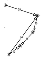
도 5 는 포인트들 (11 - 51) 로서 심볼화된 오브젝트들을 링크하는 지향된 컨스트레인트들(만)을 포함하는, 컨스트레인트들의 네트워크의 서브파트를 보여준다. 여기서, 지향된 컨스트레인트들의 상호작용은, 컨스트레인트들 (1121 - 4151) 의 임의의 놈 값들을 변형시 포인트 (51) 만이 이동될 수도 있도록 한다.Figure 5 shows a sub-part of the network of constraints, including directed constraints (only) that link the symbolized objects as points 11-51. Here, the interaction of the directed constraints allows only
도 6 은 컨스트레인트 (1151) 에 대해 새롭게 요구된 10 의 오프셋을 보여준다. 이 새롭게 요구된 값은 포인트 (51) 만을 이동시킴으로써 솔루션이 없게 만든다. CAD 시스템은 이 경우 유저에게 컨스트레인트들 해결의 불가능성을 표시함으로써 편리하게 대응할 수도 있다. 예를 들어, 윈도우가 이를 알리는 화 면에 나타날 수도 있다. 대응하는 컨스트레인트 (1151) 는 예를 들어 도 6 에서 점선으로 표시될 수도 있고, 또는 하이라이팅될 수도 있다. FIG. 6 shows the offset of 10 newly required for
본 발명에 따르면, 시스템은 더욱 순향적이 될 수도 있고, 이는 도 7 을 참조하여 설명될 것이다. 도 7 은, 유저가 도 6 의 컨스트레인트들의 네트워크를 해결할 때 유저를 돕는 GUI 에서 팝업되는 모덜 윈도우 (modal window; 110) 를 나타내는 일 예시적인 화면이다. In accordance with the present invention, the system may be more proactive, as will be described with reference to FIG. FIG. 7 is an exemplary screen showing a
여기서, 컨스트레인트들의 해결 불가능성이 검출됨에 따라, 알고리즘은, 그 컨스트레인트들이 하나의 지향된 컨스트레인트를 변형하여 풀릴 수 있는지, 또는, 필요하다면 복수의 지향된 컨스트레인트들을 변형하여 풀릴 수 있는 지 여부를 테스트하는 절차로 진행한다. 이는, 예를 들어 시스템이 해결될 수 있는 컨스트레인트를 발견할 때까지 컨스트레인트들 중 하나의 지향성을 반복적으로 무시함으로써 달성될 수 있다. 아무런 컨스트레인트도 발견되지 않는다면, 컨스트레인트들의 쌍들이 테스트 될 수도 있다. Here, as the unresolvability of the constraints is detected, the algorithm determines whether the constraints can be deformed by modifying one directed constraint or, if necessary, modifying a plurality of directed constraints Proceed to testing to see if it can be unpacked. This can be achieved, for example, by repeatedly ignoring the directionality of one of the constraints until the system finds a constraint that can be solved. If no constraints are found, the pairs of constraints may be tested.
테스트 단계는, 일 변형으로, (예를 들어 셋트의 오브젝트들의 최소의 상대적인 변위에 대응할 수도 있는) 하나의 기준 (criterion) 에 따라, 하나의 지향된 컨스트레인트를 선택하는 단계를 추가로 포함할 수도 있다. 따라서, 몇몇 컨스트레인트들이 리턴되면, 그 변형들은 해결을 허용할 수도 있고, 이 기준에 따라 특정 컨스트레인트 (그리고 관련된 오브젝트) 가 선택될 수 있다. The testing step may further include, in one variant, selecting one directed constraint (e.g., according to one criterion, which may correspond to a minimum relative displacement of the objects of the set) It is possible. Thus, if some constraints are returned, the variants may allow resolution, and a particular constraint (and related object) may be selected according to this criterion.
컨스트레인트의 지향성의 무시는 일시적이거나 아니면 영원히 이루어질 수 있고, 후자의 경우 지향된 컨스트레인트를 비지향된 컨스트레인트로 변환하기에 이 른다. 일단 이러한 컨스트레인트가 발견되면, 시스템은 어느 오브젝트 (또는 도 7 의 예의 포인트) 가 그 발견된 결정적인 컨스트레인트에 의해 영향을 받는지를 추론할 수 있다. 따라서 컨스트레인트들의 면에서 분석되는 것은 오브젝트들의 면에서 해결될 수 있고, 이것이 유저에게 더 자연스럽다. The neglect of the constraint's directivity can be transient or permanent, and in the latter case it translates the directed constraint into a non-directed constraint. Once such a constraint is found, the system can infer which object (or the example point in FIG. 7) is affected by the determined constraint. Thus, what is analyzed in terms of constraints can be solved in terms of objects, which is more natural for the user.
따라서, 모덜 윈도우 (또한 모덜 대화창) 가 나타나고, (도 7 의 모덜 윈도우에 원용된 "포인트.1" 에 대응하는) 결정적 포인트 (41) 를 이동시키는 것을 유저가 허용하도록 제안하고, 이는 알고리즘의 관점에서, 적어도 하나의 지향된 컨스트레인트를 변형하는 제안을 리턴시키기에 이른다. Thus, a modal window (also called a modal dialog) appears and suggests that the user is allowed to move the deterministic point 41 (corresponding to "point .1" cited in the modal window of FIG. 7) To return a proposal to modify at least one directed constraint.
유저가 "예" 를 클릭하면, 즉, 유저가 포인트 41 을 이동시키는 것을 수용하면, 결정적 컨스트레인트 (4151) 의 지향성이 무시되고, 컨스트레인트들이 해결된다. 그 결과는 도 8 에 나타내었다.If the user clicks Yes, i.e., the user accepts moving the
따라서, 본 발명은, 유저가 컨스트레인트들을 해결하는 데 있어서 수많은 상황들에서 실질적으로 시간을 절약할 수 있도록 돕는 CAD 전문가 시스템을 구현한다. Thus, the present invention implements a CAD expert system that helps the user to substantially save time in numerous situations in solving constraints.
다음으로, 본 발명의 일 실시형태에서, 도 9 를 참조하여 설명되는 바와 같이, GUI 는 컨스트레인트들의 지향성의 동적 변형들을 허용할 수도 있다. 도 9 는 유저가 컨스트레인트들을 편집하는 것을 돕는 모덜 윈도우를 나타내는 일 예시적인 화면이다. Next, in one embodiment of the present invention, as described with reference to Fig. 9, the GUI may allow dynamic modifications of the directivity of the constraints. Figure 9 is an exemplary screen showing a modal window that assists the user in editing constraints.
여기서, 간단함을 위해 오직 하나의 지향된 컨스트레인트 (1000) 가 GUI (100) (부분도) 에 디스플레이된다 (실제, 복수의 지향된 컨스트레인트들이 식별될 것이다). Here, for the sake of simplicity, only one directed
컨스트레인트(들) 은 제 1 오브젝트 (92) 로부터 제 2 오브젝트 (91) 로 지향되고, 이는 또한 GUI 에 디스플레이된다. 컨스트레인트는, 컨스트레인트들 해결 시에, 제 1 오브젝트 (92) 가 이동되지 않는 것을 보장한다. 바람직하게는, 전체 제품 (91 - 92) 의 업데이트를 용이하게 하기 위해, 제 1 오브젝트 (92) 의 절대적 위치가 이동되지 않는 것이 보장된다. 상기 지향된 컨스트레인트는 그 지향성을 반영하는 화살표 (1000) 로서 디스플레이된다. 제품의 오브젝트 (91 - 92) 및 컨스트레인트 (1000) 는 도 9 에서와 같이 이해할 수 있는 3D 표현으로서 디스플레이되는 것이 바람직하다. The constraint (s) are directed from the
피쳐 트리 (250) 는 도 9 의 예에서와 같이 GUI 에 디스플레이될 수 있을 것이다. 트리 (250) 는 제 1 오브젝트 ("포인트.1) (251), 제 2 오브젝트 ("포인트.2") (252) 를 나타내고, 컨스트레인트 섹션 또는 리브 (leave; 253) 를 포함한다. 본 실시예에서 이 섹션은 일단 확장되면 유일한 컨스트레인트 (즉, 디스플레이되는 컨스트레인트 (1000) 에 대응하는) 의 출현 (2531) 을 나타낸다. 나타낸 바와 같이, 이 컨스트레인트는 오브젝트 "포인트.2" 로부터 오브젝트 "포인트.1" 으로 지향된다. 트리에서 "포인트.1" 과 "포인트.2" 로서 지칭되는 오브젝트들은 참조 부호 (91 및 92) 로 화면에 디스플레이된 오브젝트들에 대응한다. 이전 실시예들에서와 같이, 문제의 컨스트레인트는 이전 실시예들에서와 마찬가지로 오프셋 포지셔닝 컨스트레인트라는 것이 또한 나타내어진다. 이 피쳐 트리 (250) 는 또한, 애플리케이션 섹션을 포함하고, 이는 유저의 행위를 통해 확장 될 수 있다. The
이러한 면에서, 컨스트레인트들은, 제품들, 파트들, 또는 컨스트레인트들에 의해 링크되는 오브젝트들에 관한 구성요소로서 데이터베이스에 저장된다. 피쳐 트리는 저장된 구성요소의 배열을 반영하고, 어쨌든 제품 (91 - 92) 의 관리 구조를 반영한다. 복잡한 제품의 경우에 트리는 수천개의 리브들을 포함할 것이고, 이는 쉽게 이해하기 힘들다.In this regard, constraints are stored in the database as components relating to objects that are linked by products, parts, or constraints. The feature tree reflects the arrangement of the stored components and, in any case, reflects the management structure of the products 91 - 92. For complex products, the tree will contain thousands of ribs, which is difficult to understand.
보다 실제적으로, 도 9 의 실시형태는 GUI 에 디스플레이된 바와 같은 컨스트레인트 (1000) 를 직접 선택함으로써, 제품 구조를 변형하는 것을 허용한다. 제품의 오브젝트들 (91 - 92) 및 컨스트레인트 (1000) 는 알기쉬운 3D 표현들로서 디스플레이되고, 유저는 화면에서 컨스트레인트를 발견하기만 하면 되고, 관리 제품 구조의 주사 라인들 대신에 화면에서 그것을 선택한다. More practically, the embodiment of FIG. 9 allows to modify the product structure by directly selecting the
컨스트레인트를 나타내는 화살표는, 예를 들어 (마우스, 트랙볼, 또는 터치스크린 등의) 포인팅 디바이스가 이용되어 유저에 의해 선택될 수도 있고, 이는 개방 모덜 윈도우 (또는 위저드) (99) 를 가져 올 것이다. Arrows representing the constraints may be selected by the user, for example using a pointing device (such as a mouse, trackball, or touch screen), which will bring an open modal window (or wizard) 99 .
따라서, GUI (100) 는 (예를 들어 유저 포인터를 이용한) 컨스트레인트의 선택 및 컨스트레인트 (1000) 의 지향성의 변형을 위한 요청을 수신하도록 설계된다 (이는 아래에서 자세히 설명될 것이다). 요청을 수신한 후에, 그에 따라 컨스트레인트는 변형되고, 입력으로서의 컨스트레인트들의 새로운 리스트를 식별하게 될 것이다 (도 2 의 단계 S10 참조). Thus, the
모덜 윈도우 (99) 는 하나 이상의 다음 필드들 (93 - 98) 을 포함할 수도 있 다. 이 필드들의 각각은, 당해 기술분야에서 통상적인, 필드 데이터의 스크롤/편집/변형을 가능하게 하는 적절한 도구들 또는 제어들에 의해 보충될 수도 있다.The
필드 (93) 에서, 오프셋의 현재 값이 디스플레이되고, 이는 드롭 다운 리스트를 이용하여 유저에 의해 변경될 수 있다. In
필드 (94) 에서, 실제 컨스트레인트에 따라, 컨스트레인트의 현재의 상태 또는 관계가 유저에게 디스플레이된다 (예를 들어, "제 2 요소 이동 가능 (포인트.1)"). 드롭 다운 리스트를 이용하여 유저는 (라인 94a 를 선택하여) 컨스트레인트를 비지향된 컨스트레인트로 변경할 수도 있고, (라인 94b 내지 94c 를 선택하여) 컨스트레인트의 지향성을 반전시킬 수도 있다. 따라서, 컨스트레인트의 지향성을 변형하는 다양한 방식들이 유저에게 이용가능하다. In
필드 (97) 는, 피쳐 트리 (250) 의 리브 (2531) 에 대응하는, 바람직하게는 유저가 변형가능한 (텍스트 박스), 컨스트레인트의 현재 명칭을 디스플레이한다.The
섹션 (98) 은 화면에서 91 및 92 로 디스플레이된 링크된 오브젝트들 (251, 252) 에 관한 정보를 디스플레이한다.
편집 후에, 유저는 컨스트레인트를 변형하게 되는 "OK" 버튼을 누를 수 있고, 또는 "취소" 버튼을 누를 수도 있다. After editing, the user may press the "OK" button to modify the constraint, or the "Cancel"
따라서, 모덜 윈도우 (99) 는 네트워크들의 컨스트레인트들의 지향성 (및 가능하면 다른 피쳐들) 을 변형하는 것을 허용한다. Thus, the
변형으로는, 컨스트레인트들의 네트워크가 초기에 지향된 컨스트레인트들로만 이루어진 경우, 모덜 윈도우는 더욱 특히 관리자를 위해 의도될 수도 있고, 따 라서, 따라서, 컨스트레인트 지향성들만 반전시키고 놈 값은 변경하지 않을 수도 있다. As a variant, if the network of constraints consists solely of initially directed constraints, then the modal window may be more specifically intended for the manager, and therefore, therefore, only the constraint directives are reversed and the norm value is changed It may not.
또 다른 변형으로는, 모덜 윈도우는 더욱 특히 설계자를 위해 의도될 수도 있고, 따라서, 오프셋 값을 변경시키는 것을 허용하고, 컨스트레인트 지향성들을 반전시키지 않도록 할 수도 있다. In yet another variation, the modal window may be more particularly intended for the designer, thus allowing changing the offset value and not inverting the constraint directivities.
더욱 일반적으로, 모덜 윈도우의 기능들은 (예를 들어 허가가 필요한) 소정의 액세스 권한들에 따라 변할 수도 있다.More generally, the functions of the modal window may vary according to certain access rights (e.g., permission is required).
본 발명은 도면을 참조하여 설명한 바람직한 실시형태들로 한정되는 것은 아니다. 특히, 컨스트레인트들을 포지셔닝시키기 위해 오프셋만이 본 발명의 실시형태들을 설명하는데 이용되었지만, 다른 타입들의 컨스트레인트들이 고려될 수도 있다. 따라서, 본 발명은 각, 평행, 접촉, 일치, 키럴 (chiral), 또는 위상적 컨스트레인트들에도 또한 적용될 수도 있다. 최종적으로, 일 실시형태에서, 본 발명에 따른 컨스트레인트는 2 개의 오브젝트들을 링크하는 임의의 관계로서 이해될 수 있을 것이다. The present invention is not limited to the preferred embodiments described with reference to the drawings. In particular, although only offsets are used to describe embodiments of the present invention to position constraints, other types of constraints may be considered. Thus, the present invention may also be applied to angular, parallel, contact, coincidence, chiral, or topological constraints. Finally, in one embodiment, a constraint according to the present invention may be understood as any relationship linking two objects.
또한, 본 발명에 따른 프로세스는, 모든 관련된 사람들 및 조직이 권한을 가지고 판독 및 기록 액세스 권한들을 가지는 공동 작업 엔지니어링 환경에 관한 것이다. 이러한 경우, 본 발명에 따른 프로세스는 해결 불가능성에 직면한 소정의 유저/설계자가, 또 다른 유저/설계자에 의해 소유된 오브젝트를 이동하도록 하는 권한 (판독/기록 액세스) 을 요구할 수 있도록 한다. 이들 두 (또는 그 이상) 유저들 중 어느 누구도 컨스트레인트들의 네트워크를 분석하여 시스템에 대한 솔루션을 발견할 수 없고, 프로세스가 유저들을 위해 그것을 해결한다. 유저들은 사전 처리된 솔루션을 유효화하도록 요청받기만 하고, 그들은 모든 스펙이 고려되는 것을 보장받는다. The process according to the present invention is also directed to a collaborative engineering environment in which all relevant persons and organizations have rights to read and write access. In such a case, the process according to the present invention allows a given user / designer, who is confronted with unresolvability, to request authorization (read / write access) to move objects owned by another user / designer. None of these two (or more) users can analyze the network of constraints to discover a solution for the system, and the process solves it for users. Users are only asked to validate the preprocessed solution, and they are guaranteed that all specifications are taken into consideration.
도 1 은 CAD 시스템의 그래픽 유저 인터페이스의 일 예시적인 화면이고, 이는 지향된 컨스트레인트들에 의해 링크된 오브젝트들의 모습을 나타낸다. Figure 1 is an exemplary view of a graphical user interface of a CAD system, which illustrates the appearance of objects linked by directed constraints.
도 2 는 컨스트레인트들의 하이브리드 네트워크를 해결하는 단계들을 나타내는 플로우차트이다. 2 is a flow chart illustrating steps for solving a hybrid network of constraints;
도 3 은 지향된 컨스트레인트들과 비지향된 컨스트레인트들 양자에 의해 링크된 파트들의 모습의 일 예시적인 화면이다. Figure 3 is an exemplary view of the appearance of parts linked by both directed constraints and non-directed constraints.
도 4 는 도 3 의 모습을 나타내는 CAD 시스템 디스플레이의 일 예시적인 화면이고, 여기서, 몇몇 컨스트레인트들이 유저의 행위에 의해 지향되었다. FIG. 4 is an exemplary view of a CAD system display showing the appearance of FIG. 3, wherein some constraints are directed by the user's actions.
도 5 및 도 6 은 유저에 의해 컨스트레인트의 오프셋 값을 변경시키기 위한 유저 요청을 개략적으로 나타낸다.Figures 5 and 6 schematically illustrate a user request to change the constraint's offset value by the user.
도 7 은 도 6 의 컨스트레인트들의 네트워크를 해결하는데 있어 유저를 돕는 모덜 윈도우 (modal window) 를 나타내는 일 예시적인 화면이다. Figure 7 is an exemplary view illustrating a modal window that assists the user in solving the network of constraints of Figure 6;
도 8 은 해결 후의 도 7 의 컨스트레인트들의 네트워크를 나타낸다. Figure 8 shows the network of constraints of Figure 7 after resolution.
도 9 는 컨스트레인트를 편집하는데 있어 유저를 돕는 모덜 윈도우를 나타내는 일 예시적인 화면이다.Figure 9 is an exemplary screen showing a modal window that assists the user in editing the constraint.
Claims (16)
Applications Claiming Priority (2)
| Application Number | Priority Date | Filing Date | Title |
|---|---|---|---|
| EP06292061.6 | 2006-12-28 | ||
| EP06292061A EP1939771A1 (en) | 2006-12-28 | 2006-12-28 | Method and a computer program product for computer aided design of a product comprising a set of constrained objects |
Publications (2)
| Publication Number | Publication Date |
|---|---|
| KR20080063218A KR20080063218A (en) | 2008-07-03 |
| KR101463246B1 true KR101463246B1 (en) | 2014-11-18 |
Family
ID=37901224
Family Applications (1)
| Application Number | Title | Priority Date | Filing Date |
|---|---|---|---|
| KR1020070141061A Active KR101463246B1 (en) | 2006-12-28 | 2007-12-28 | Method and computer program product of a product comprising a set of constrained objects |
Country Status (6)
| Country | Link |
|---|---|
| US (1) | US7613594B2 (en) |
| EP (1) | EP1939771A1 (en) |
| JP (1) | JP5183194B2 (en) |
| KR (1) | KR101463246B1 (en) |
| CN (1) | CN101226559A (en) |
| CA (1) | CA2616226A1 (en) |
Families Citing this family (26)
| Publication number | Priority date | Publication date | Assignee | Title |
|---|---|---|---|---|
| US8541795B2 (en) | 2004-10-12 | 2013-09-24 | Cree, Inc. | Side-emitting optical coupling device |
| US20080172208A1 (en) * | 2006-12-28 | 2008-07-17 | Dassault Systems | Method and computer program product of computer aided design of a product comprising a set of constrained objects |
| US8773425B2 (en) * | 2007-05-01 | 2014-07-08 | M.E.P. CAD Inc. | Methods and apparatuses for proposing resolutions to conflicts in a CAD drawing with reflections |
| US8584099B1 (en) * | 2007-06-29 | 2013-11-12 | Carnegie Mellon University | Apparatuses and methods for producing runtime architectures of computer program modules |
| US9557033B2 (en) | 2008-03-05 | 2017-01-31 | Cree, Inc. | Optical system for batwing distribution |
| EP2261826A1 (en) | 2009-06-05 | 2010-12-15 | Dassault Systèmes | Process of updating a status of relation between objects in a system of computer-aided design of objects |
| EP2261827B1 (en) | 2009-06-10 | 2015-04-08 | Dassault Systèmes | Process, program and apparatus for displaying an assembly of objects of a PLM database |
| CN102782686A (en) * | 2009-11-04 | 2012-11-14 | 数码成型有限公司 | Improvements relating to user interfaces for designing objects |
| EP2333683A1 (en) * | 2009-11-06 | 2011-06-15 | Dassault Systèmes | Method and system for designing an assembly of objects in a system of computer-aided design |
| EP2333682B1 (en) * | 2009-11-06 | 2020-05-20 | Dassault Systèmes | Method and system for designing an assembly of objects in a system of computer-aided design |
| US20110252163A1 (en) * | 2010-04-09 | 2011-10-13 | Microsoft Corporation | Integrated Development Environment for Rapid Device Development |
| JP2012003425A (en) * | 2010-06-15 | 2012-01-05 | Toshiba Corp | Design support system and design support method |
| FR2975202B1 (en) * | 2011-05-10 | 2013-05-10 | Cameleon Software | DEVICE FOR PRODUCING A DEFINITION OF A VERSION OF A PRODUCT |
| EP2523129B1 (en) * | 2011-05-11 | 2020-07-01 | Dassault Systèmes | Selection of a manipulator of an object among a plurality of manipulators |
| EP2746972B1 (en) * | 2012-12-20 | 2019-03-20 | Dassault Systèmes | Designing an assembly of parts in a three-dimensional scene |
| CN103226628B (en) * | 2013-03-22 | 2016-06-22 | 北京汽车研究总院有限公司 | Automobile fore suspension and rear suspension tire enveloping surface rapid generation and device |
| US9235659B2 (en) * | 2014-03-17 | 2016-01-12 | Siemens Product Lifecycle Management Software Inc. | Local behavior in a variational system |
| EP2921978B1 (en) * | 2014-03-19 | 2021-09-29 | Dassault Systèmes | Designing industrial products by using geometries connected by geometrical constraints |
| US20150278400A1 (en) * | 2014-03-28 | 2015-10-01 | Siemens Product Lifecycle Management Software Inc. | Hybrid variational solving in cad models |
| EP2990969A1 (en) * | 2014-08-26 | 2016-03-02 | Dassault Systèmes | Criterion for sequential update |
| EP2990970A1 (en) | 2014-08-26 | 2016-03-02 | Dassault Systèmes | Execution of sequential update |
| US10429437B2 (en) * | 2015-05-28 | 2019-10-01 | Keysight Technologies, Inc. | Automatically generated test diagram |
| US20180189996A1 (en) * | 2015-06-12 | 2018-07-05 | Naturalmotion Limited | Animating a virtual object |
| KR102425638B1 (en) * | 2018-02-05 | 2022-07-27 | 미스미 코포레이숀 | Design assistance system |
| CN112970023A (en) * | 2018-09-04 | 2021-06-15 | 西门子工业软件有限公司 | Counter-constraint configuration and implementation for computer-aided design (CAD) models |
| KR102228293B1 (en) * | 2019-05-21 | 2021-03-16 | (주)심스리얼리티 | System for creating simulation data and method using the same |
Citations (3)
| Publication number | Priority date | Publication date | Assignee | Title |
|---|---|---|---|---|
| JPH09161097A (en) * | 1995-12-07 | 1997-06-20 | Matsushita Electric Ind Co Ltd | Graphic processing apparatus and graphic processing method |
| JP3251877B2 (en) | 1996-05-18 | 2002-01-28 | インターナショナル・ビジネス・マシーンズ・コーポレーション | Three-dimensional grid generation method and system |
| US6385563B1 (en) | 1998-11-10 | 2002-05-07 | Autodesk, Inc. | Reusable design model and apparatus |
Family Cites Families (13)
| Publication number | Priority date | Publication date | Assignee | Title |
|---|---|---|---|---|
| US5617510A (en) * | 1989-06-13 | 1997-04-01 | Schlumberger Technology Corporation | Dependency graph solution for constraint systems |
| JPH0789382B2 (en) * | 1991-03-14 | 1995-09-27 | インターナショナル・ビジネス・マシーンズ・コーポレイション | Method and apparatus for generating shape model |
| US7043407B2 (en) * | 1997-03-10 | 2006-05-09 | Trilogy Development Group, Inc. | Method and apparatus for configuring systems |
| US5572639A (en) * | 1995-05-08 | 1996-11-05 | Gantt; Brian D. | Method and apparatus for interactively manipulating and displaying presumptive relationships between graphic objects |
| US6016147A (en) * | 1995-05-08 | 2000-01-18 | Autodesk, Inc. | Method and system for interactively determining and displaying geometric relationships between three dimensional objects based on predetermined geometric constraints and position of an input device |
| AU2382300A (en) * | 1998-12-23 | 2000-07-12 | National Institute Of Standards And Technology ("Nist") | Method and system for a virtual assembly design environment |
| US7768526B2 (en) * | 2000-11-15 | 2010-08-03 | Autodesk, Inc. | Graphical object generation and regeneration |
| US7176942B2 (en) * | 2001-03-23 | 2007-02-13 | Dassault Systemes | Collaborative design |
| US6907573B2 (en) * | 2001-09-28 | 2005-06-14 | Autodesk, Inc. | Intelligent constraint definitions for assembly part mating |
| US20050060130A1 (en) * | 2003-07-25 | 2005-03-17 | Vadim Shapiro | Modeling and analysis of objects having heterogeneous material properties |
| US7725299B2 (en) * | 2004-03-01 | 2010-05-25 | Purdue Research Foundation | Multi-tier and multi-domain distributed rapid product configuration and design system |
| US7899756B2 (en) * | 2004-12-01 | 2011-03-01 | Xerox Corporation | Critical parameter/requirements management process and environment |
| US20080172208A1 (en) * | 2006-12-28 | 2008-07-17 | Dassault Systems | Method and computer program product of computer aided design of a product comprising a set of constrained objects |
-
2006
- 2006-12-28 EP EP06292061A patent/EP1939771A1/en not_active Ceased
-
2007
- 2007-12-21 CA CA002616226A patent/CA2616226A1/en not_active Abandoned
- 2007-12-27 US US11/965,403 patent/US7613594B2/en active Active
- 2007-12-27 CN CNA2007101441730A patent/CN101226559A/en active Pending
- 2007-12-28 KR KR1020070141061A patent/KR101463246B1/en active Active
- 2007-12-28 JP JP2007340979A patent/JP5183194B2/en active Active
Patent Citations (3)
| Publication number | Priority date | Publication date | Assignee | Title |
|---|---|---|---|---|
| JPH09161097A (en) * | 1995-12-07 | 1997-06-20 | Matsushita Electric Ind Co Ltd | Graphic processing apparatus and graphic processing method |
| JP3251877B2 (en) | 1996-05-18 | 2002-01-28 | インターナショナル・ビジネス・マシーンズ・コーポレーション | Three-dimensional grid generation method and system |
| US6385563B1 (en) | 1998-11-10 | 2002-05-07 | Autodesk, Inc. | Reusable design model and apparatus |
Also Published As
| Publication number | Publication date |
|---|---|
| US20080162091A1 (en) | 2008-07-03 |
| EP1939771A1 (en) | 2008-07-02 |
| JP5183194B2 (en) | 2013-04-17 |
| KR20080063218A (en) | 2008-07-03 |
| US7613594B2 (en) | 2009-11-03 |
| JP2008165809A (en) | 2008-07-17 |
| CA2616226A1 (en) | 2008-06-28 |
| CN101226559A (en) | 2008-07-23 |
Similar Documents
| Publication | Publication Date | Title |
|---|---|---|
| KR101463246B1 (en) | Method and computer program product of a product comprising a set of constrained objects | |
| US20080172208A1 (en) | Method and computer program product of computer aided design of a product comprising a set of constrained objects | |
| JP5697950B2 (en) | Method and system for designing an assembly of objects in a computer aided design system | |
| US10152198B2 (en) | Method and system for editing a product assembly | |
| US8686997B2 (en) | Method and system for composing an assembly | |
| KR101649096B1 (en) | Method and system for designing an assembly of objects in a system of computer-aided design | |
| US9390201B2 (en) | Merging of modeled objects | |
| CN105389412B (en) | Execution of sequential updates | |
| EP1672533B1 (en) | Method and computer system for interacting with a database | |
| CN105389413B (en) | Guidelines for Sequential Updates | |
| JP5623796B2 (en) | The process of updating the status of relationships between objects within a system of computer-aided design of objects | |
| US8768654B2 (en) | Interactive configuration-management-based diagramming tool | |
| Marchenko et al. | A new method of visualization and documentation of parametric information of 3D CAD models | |
| EP1939772A1 (en) | Method and a computer program product for computer aided design of a product comprising a set of constrained objects | |
| Inventor et al. | Autodesk® | |
| Tickoo | Creo Parametric 4.0 for Designers | |
| WO2016069287A2 (en) | System and Method for Configuration-Managed Lifecycle Diagrams | |
| Fucci | The evolution of digital tools for product design |
Legal Events
| Date | Code | Title | Description |
|---|---|---|---|
| PA0109 | Patent application |
Patent event code: PA01091R01D Comment text: Patent Application Patent event date: 20071228 |
|
| PG1501 | Laying open of application | ||
| A201 | Request for examination | ||
| PA0201 | Request for examination |
Patent event code: PA02012R01D Patent event date: 20121210 Comment text: Request for Examination of Application Patent event code: PA02011R01I Patent event date: 20071228 Comment text: Patent Application |
|
| E902 | Notification of reason for refusal | ||
| PE0902 | Notice of grounds for rejection |
Comment text: Notification of reason for refusal Patent event date: 20140422 Patent event code: PE09021S01D |
|
| E701 | Decision to grant or registration of patent right | ||
| PE0701 | Decision of registration |
Patent event code: PE07011S01D Comment text: Decision to Grant Registration Patent event date: 20141008 |
|
| GRNT | Written decision to grant | ||
| PR0701 | Registration of establishment |
Comment text: Registration of Establishment Patent event date: 20141112 Patent event code: PR07011E01D |
|
| PR1002 | Payment of registration fee |
Payment date: 20141112 End annual number: 3 Start annual number: 1 |
|
| PG1601 | Publication of registration | ||
| FPAY | Annual fee payment |
Payment date: 20171103 Year of fee payment: 4 |
|
| PR1001 | Payment of annual fee |
Payment date: 20171103 Start annual number: 4 End annual number: 4 |