KR101360687B1 - Switch identification system for vehicle - Google Patents
Switch identification system for vehicle Download PDFInfo
- Publication number
- KR101360687B1 KR101360687B1 KR1020120116502A KR20120116502A KR101360687B1 KR 101360687 B1 KR101360687 B1 KR 101360687B1 KR 1020120116502 A KR1020120116502 A KR 1020120116502A KR 20120116502 A KR20120116502 A KR 20120116502A KR 101360687 B1 KR101360687 B1 KR 101360687B1
- Authority
- KR
- South Korea
- Prior art keywords
- switch
- slot
- vehicle
- terminal
- resistance
- Prior art date
- Legal status (The legal status is an assumption and is not a legal conclusion. Google has not performed a legal analysis and makes no representation as to the accuracy of the status listed.)
- Active
Links
Images


Classifications
-
- B—PERFORMING OPERATIONS; TRANSPORTING
- B60—VEHICLES IN GENERAL
- B60R—VEHICLES, VEHICLE FITTINGS, OR VEHICLE PARTS, NOT OTHERWISE PROVIDED FOR
- B60R16/00—Electric or fluid circuits specially adapted for vehicles and not otherwise provided for; Arrangement of elements of electric or fluid circuits specially adapted for vehicles and not otherwise provided for
- B60R16/005—Electro-mechanical devices, e.g. switched
-
- H—ELECTRICITY
- H01—ELECTRIC ELEMENTS
- H01H—ELECTRIC SWITCHES; RELAYS; SELECTORS; EMERGENCY PROTECTIVE DEVICES
- H01H9/00—Details of switching devices, not covered by groups H01H1/00 - H01H7/00
- H01H9/08—Arrangements to facilitate replacement of a switch, e.g. cartridge housing
-
- H—ELECTRICITY
- H05—ELECTRIC TECHNIQUES NOT OTHERWISE PROVIDED FOR
- H05K—PRINTED CIRCUITS; CASINGS OR CONSTRUCTIONAL DETAILS OF ELECTRIC APPARATUS; MANUFACTURE OF ASSEMBLAGES OF ELECTRICAL COMPONENTS
- H05K5/00—Casings, cabinets or drawers for electric apparatus
- H05K5/06—Hermetically-sealed casings
- H05K5/069—Other details of the casing, e.g. wall structure, passage for a connector, a cable, a shaft
-
- H—ELECTRICITY
- H01—ELECTRIC ELEMENTS
- H01H—ELECTRIC SWITCHES; RELAYS; SELECTORS; EMERGENCY PROTECTIVE DEVICES
- H01H2231/00—Applications
- H01H2231/026—Car
Landscapes
- Engineering & Computer Science (AREA)
- Mechanical Engineering (AREA)
- Microelectronics & Electronic Packaging (AREA)
- Keying Circuit Devices (AREA)
Abstract
본 발명은 차량용 스위치 인식 장치에 관한 것으로, 간단한 회로 구성으로 스위치가 임의의 슬롯에 설치되더라도 각 슬롯에 설치된 스위치들을 개별 인식할 수 있도록 구성됨으로써, 차량에서 스위치를 원하는 위치에 자유롭게 설치할 수 있고, 궁극적으로 스위치들을 보다 효율적으로 운용할 수 있도록 해주는 스위치 인식 장치을 제공하고자 한다.
이를 위하여, 본 발명은 차량용 스위치 인식 장치에 있어서, 차량의 슬롯에 삽입된 스위치를 인식하는 스위치 인식 장치에 있어서, 접지단자와 2개의 저항단자로 이루어져 상기 스위치에 구비되며, 슬롯에 스위치가 삽입될 때 슬롯 내 대응단자에 접속되는 인식단자; 상기 스위치에서 인식단자에 연결되고 스위치별로 설정된 상이한 저항값을 갖는 저항; 상기 슬롯 내 대응단자에 연결된 입력단회로를 통해 스위치 내 상기 저항의 저항값에 따른 신호를 입력받아 스위치의 종류를 인식하는 제어모듈을 포함한다.The present invention relates to a switch recognition device for a vehicle, and is configured to recognize the switches installed in each slot even if the switch is installed in any slot by a simple circuit configuration, the switch can be freely installed in the desired position in the vehicle, ultimately To provide a switch recognition device that can operate the switch more efficiently.
To this end, the present invention is a switch recognition device for a vehicle, a switch recognition device for recognizing a switch inserted in the slot of the vehicle, comprising a ground terminal and two resistance terminals are provided in the switch, the switch is inserted into the slot A recognition terminal connected to the corresponding terminal in the slot; A resistor connected to the recognition terminal in the switch and having a different resistance value set for each switch; It includes a control module for receiving a signal according to the resistance value of the resistance in the switch through an input terminal circuit connected to the corresponding terminal in the slot to recognize the type of the switch.
Description
본 발명은 차량용 스위치 인식 장치에 관한 것으로, 더욱 상세하게는 차량에서 스위치가 임의의 슬롯에 삽입되어 설치되더라도 각 슬롯에 설치된 스위치들을 개별 인식할 수 있는 차량용 스위치 인식 장치에 관한 것이다.
The present invention relates to a vehicle switch recognition device, and more particularly, to a vehicle switch recognition device that can individually recognize the switches installed in each slot even if the switch is inserted into any slot in the vehicle.
일반적으로, 차량에는 램프류 및 전장품, 편의장치, 안전장치 등을 포함하여 각종 차량 장치 및 시스템을 조작하기 위한 다수의 스위치가 구비되어 있다.In general, a vehicle is provided with a plurality of switches for operating various vehicle devices and systems, including lamps, electrical appliances, convenience devices, safety devices, and the like.
이러한 스위치들은 차량 내 여러 위치에 설치되어 사용되는데, 도 1에 나타낸 바와 같이 스위치(11~14)들이 운전자가 편리하게 선택하여 조작할 수 있는 운전석 주변의 인스트루먼트 패널에 주로 설치되고 있다.These switches are installed and used in various positions in the vehicle, and as shown in FIG. 1, the
특히 다수의 스위치(11~14)들이 클러스터 주변으로 집중 배치되는데, 트럭이나 버스 등 대형 상용차량인 경우 인스트루먼트 패널에 설치되는 스위치(11~14)의 개수만도 대략 30 ~ 40여 가지나 된다.In particular, a plurality of
또한 이렇게 많은 스위치가 모든 차량에 대해서 동일하게 사용되는 것이 아니라, 차량의 모델이나 차종에 따라 선택적으로 사용되고 있고, 무엇보다 각각의 스위치가 차량 내 정해진 고정 위치에 설치되고 있다.In addition, so many switches are not used equally for all vehicles, but are selectively used according to the model and the vehicle model of the vehicle, and above all, each switch is installed at a fixed fixed position in the vehicle.
스위치들이 각각의 정해진 고정 위치에서 그 입력을 받아들이는 상대 유니트와 와이어링으로 연결되는데, 각 위치에 설치된 개별 스위치를 식별해줄 수 있는 구성이 없으므로, 각 스위치의 설치 위치(스위치가 삽입되는 슬롯)를 미리 정해진 위치로 고정해야 하는 것이다.The switches are wired to the mating unit which accepts their inputs at each fixed position. There is no configuration to identify the individual switches installed at each position. It should be fixed to a predetermined position.
이에 스위치의 종류별(용도 및 기능별)로 각각의 설치 위치를 미리 정해놓고(스위치 종류별 슬롯 및 와이어링 고정), 정해진 위치에 스위치가 설치된 뒤 조작되면, 조작에 따른 신호의 위치로부터(조작 위치로부터, 즉 신호가 들어오는 슬롯 및 와이어링 위치로부터) 스위치가 구분될 수 있다. Therefore, each installation position is determined in advance by the type of the switch (by use and function) (slot and wiring fixed by the switch type), and when the switch is installed in a predetermined position and operated, the position of the signal according to the operation (from the operation position, That is, from the slot into which the signal comes in and from the wiring location).
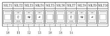
또한 차량의 모델별, 차종별 스위치의 적용 여부에 따라 특정 슬롯에 스위치가 필요 없는 경우, 통상 도 2에 나타낸 바와 같이 그 자리(슬롯)를 블랭킹 커버나 플러그(plug)(18) 등으로 덮어주고, 사용되는 스위치(11~14)만 미리 고정된 위치에 삽입하여 설치하게 된다.In addition, when a switch is not required for a specific slot according to whether a switch according to a model of a vehicle or a vehicle is applied, a seat cover is normally covered with a blanking cover or a
스위치가 종류별로 고정된 레이아웃 자리에서만 조작상태를 전달할 수 있는 구조이므로, 스위치(11~14)를 원하는 위치에 설치하지 못하고 반드시 정해진 고정 위치에만 설치한 뒤, 나머지 미사용되는 스위치 자리에 대해서는 블랭킹 커버나 플러그(18)로 덮어주는 것이다.Since the switch can transmit the operation status only in the layout position fixed according to the type, the
이와 같이 스위치와 와이어링 연결 구조가 특정 위치로 고정되어 있다면, 개별 스위치의 레이아웃 자유도가 떨어져 인스트루먼트 패널 주위에 스위치 자리만 30 ~ 40개가 마련되어야 한다.If the switch and the wiring connection structure is fixed in a specific position as described above, 30-40 switch positions should be provided around the instrument panel due to the lack of layout freedom of individual switches.
이는 인스트루먼트 주변이 온통 스위치 자리 면이 되어 디자인 자유도를 저하시키고, 운전자 편의에 따라 스위치 위치를 재배열하거나 스위치 위치를 이동시키는 것이 불가능하여 다양해지는 운전자 요구를 충족시킬 수 없게 된다.This results in a switch seat all around the instrument, which reduces design freedom and makes it impossible to rearrange or move the switch position according to the operator's convenience, thus failing to meet diversified driver demands.
예컨대, 특정 스위치의 위치를 도 1의 'A' 위치에서 'B' 위치로 이동 및 재배열하는 것이 불가능하다.For example, it is not possible to move and rearrange the position of a particular switch from the 'A' position of FIG. 1 to the 'B' position.
또한 도 2에서 알 수 있는 바와 같이 차량에서 사용하지 않는 스위치 자리에 블랭킹 커버나 플러그(18)만 설치하고, 정작 필요한 스위치(11~14)들은 정해진 여러 위치로 분산하여 배치하게 된다.In addition, as shown in FIG. 2, only a blanking cover or a
결국, 많은 스위치 중 운전자가 자주 사용하는 스위치나 긴급히 사용해야 하는 스위치는 운전자가 쉽게 조작할 수 있도록 근접된 위치에 설치되어야 하지만, 차량의 모델별, 차종별로 사용하는 스위치가 각각 다르므로, 전체 자리 중 일부 고정된 자리에만 스위치가 설치된 상태에서, 운전자가 필요한 스위치를 선택 조작하는데 어려움이 있다.After all, the switch frequently used by the driver or the switch which is urgently needed should be installed in a close position so that the driver can easily operate the switch.However, the switches used by the model and the vehicle type are different. With switches installed only in some fixed positions, it is difficult for the operator to select and operate the required switches.
더욱이 도 2에 나타낸 스위치 모듈에서 사용하지 않는 다수의 블랭킹 커버나 플러그(18)들이 스위치(11~14)의 중간 중간에 분산 배치되므로, 운전자가 전체 스위치 배열 중 신속히 필요한 스위치를 찾아 조작하는데 어려움이 있는 것이다.Furthermore, since a plurality of blanking covers or
운전자가 인스트루먼트 패널의 스위치를 조작하는데 어려움을 겪게 된다면, 스위치의 조작을 위해 운전의 집중력을 떨어뜨리므로 사고의 위험을 발생시킬 수 있다.If the driver has difficulty in operating the switch of the instrument panel, the driver can reduce the concentration of driving for the operation of the switch, which may cause an accident.
차량 제조사 입장에서도 스위치의 위치를 일일이 확인하여 정해진 자리에 스위치를 삽입, 설치해야 하고, 여러 개의 블랭킹 커버나 플러그들도 미사용 위치를 확인하여 설치해야 하므로, 작업성 및 생산성 측면에서 불리함이 있다.In the vehicle manufacturer's position, the position of the switch must be checked in order to install and install the switch at a predetermined position, and a plurality of blanking covers or plugs must be installed to confirm the unused position, which is disadvantageous in terms of workability and productivity.
또한 모델 및 차종에 따라 스위치들을 선택적으로 설치함에 있어서, 협소한 공간에 주요 스위치들이 여러 위치에 분산 배치됨과 더불어, 블랭킹 커버나 플러그가 불필요하게 공간을 점유하므로, 공간 활용도 측면에서 효율적이지 못하다.In addition, in the selective installation of switches according to models and models, since the main switches are distributed in various locations in a narrow space and a blanking cover or a plug occupies the space unnecessarily, it is not efficient in terms of space utilization.
만약 스위치가 원하는 위치에 배치된 레이아웃을 얻고자 한다면, 스위치 선택 적용에 따른 다양한 경우의 수를 고려하여 여러 종류의 스위치 모듈(스위치 모듈의 일례는 도 2와 같음)을 제작해야 한다.In order to obtain a layout in which the switch is arranged at a desired position, various types of switch modules (an example of a switch module is the same as FIG. 2) should be manufactured in consideration of the number of various cases according to the switch selection application.
그러나, 스위치 모듈을 차량의 모델 및 차종별로 모두 제작하고 관리하기 위해서는 스위치 모듈의 수가 많아지므로 추가적인 비용과 시간, 인력의 투입이 필요하다(사양 관리가 매우 어려움).
However, in order to manufacture and manage the switch module by vehicle model and vehicle type, the number of switch modules increases, so additional cost, time, and manpower are required (specific management is difficult).
상기와 같은 종래 기술의 문제점을 해결하기 위하여, 본 발명은 간단한 회로 구성으로 스위치가 임의의 슬롯에 설치되더라도 각 슬롯에 설치된 스위치들을 개별 인식할 수 있도록 구성됨으로써, 차량에서 스위치를 원하는 위치에 자유롭게 설치할 수 있고, 궁극적으로 스위치들을 보다 효율적으로 운용할 수 있도록 해주는 스위치 인식 장치를 제공하는데 그 목적이 있다.In order to solve the problems of the prior art as described above, the present invention is configured to recognize individual switches installed in each slot even if the switch is installed in any slot by a simple circuit configuration, thereby freely installing the switch in the desired position in the vehicle It is an object of the present invention to provide a switch recognition device that can enable and ultimately operate the switches more efficiently.
본 발명의 목적들은 이상에서 언급한 목적으로 제한되지 않으며, 언급되지 않은 본 발명의 다른 목적 및 장점들은 하기의 설명에 의해서 이해될 수 있으며, 본 발명의 실시예에 의해 보다 분명하게 알게 될 것이다. 또한, 본 발명의 목적 및 장점들은 특허 청구 범위에 나타낸 수단 및 그 조합에 의해 실현될 수 있음을 쉽게 알 수 있을 것이다.
The objects of the present invention are not limited to the above-mentioned objects, and other objects and advantages of the present invention which are not mentioned can be understood by the following description, and will be more clearly understood by the embodiments of the present invention. It will also be readily apparent that the objects and advantages of the invention may be realized and attained by means of the instrumentalities and combinations particularly pointed out in the appended claims.
상기 목적을 달성하기 위한 본 발명의 장치는, 차량의 슬롯에 삽입된 스위치를 인식하는 스위치 인식 장치에 있어서, 접지단자와 2개의 저항단자로 이루어져 상기 스위치에 구비되며, 슬롯에 스위치가 삽입될 때 슬롯 내 대응단자에 접속되는 인식단자; 상기 스위치에서 인식단자에 연결되고 스위치별로 설정된 상이한 저항값을 갖는 저항; 상기 슬롯 내 대응단자에 연결된 입력단회로를 통해 스위치 내 상기 저항의 저항값에 따른 신호를 입력받아 스위치의 종류를 인식하는 제어모듈을 포함한다.
An apparatus of the present invention for achieving the above object is a switch recognition device for recognizing a switch inserted in a slot of a vehicle, comprising a ground terminal and two resistance terminals provided in the switch, when the switch is inserted into the slot A recognition terminal connected to a corresponding terminal in the slot; A resistor connected to the recognition terminal in the switch and having a different resistance value set for each switch; It includes a control module for receiving a signal according to the resistance value of the resistance in the switch through an input terminal circuit connected to the corresponding terminal in the slot to recognize the type of the switch.
상기와 같은 본 발명은 스위치를 임의의 슬롯에 설치하더라도 제어모듈이 스위치의 종류를 인식할 수 있고, 결국 원하는 위치에 스위치를 자유롭게 배치할 수 있게 된다.According to the present invention as described above, even if the switch is installed in any slot, the control module can recognize the type of the switch, and thus, the switch can be freely disposed at a desired position.
특히 간단히 슬롯에 스위치만 꽂아주게 되면 제어모듈이 스위치의 종류를 구분해서 식별할 수 있으므로 스위치의 자유로운 배치가 가능해져 사용자 편의대로 스위치들을 배열할 수 있고, 사용 빈도에 따라 조작성이 좋은 위치에 순서대로 스위치를 배치하는 것이 가능하다.Particularly, simply plugging the switch into the slot allows the control module to identify the type of switch so that the switch can be arranged freely, so that the switches can be arranged at the user's convenience. It is possible to place a switch.
궁극적으로는 운전자가 손쉽게 조작할 수 있는 근접된 위치에 스위치를 자유롭게 배열할 수 있으므로 조작의 편의성 증대, 운전 부주의로 인한 교통사고 방지, 운전 편의성 증대 등의 효과가 있다.Ultimately, the switch can be freely arranged in a close position where the driver can easily operate, thereby increasing convenience of operation, preventing accidents due to inadvertent driving, and increasing driving convenience.
또한 레이아웃 자유도의 증대로 디자인 측면에서 매우 유리해지며, 사양 관리가 용이해지고, 조립 작업성이 증대되는 등의 이점이 있다.In addition, the increase in the degree of freedom of layout is very advantageous in terms of design, there are advantages such as easy specification management, increased workability of assembly.
또한 차량의 모델이나 차종에 따라 사용 스위치의 개수에 맞추어 슬롯을 구비하게 되면 종래와 같이 다수의 블랭킹 커버나 플러그를 사용하지 않아도 되며, 남는 공간을 포켓 등으로 활용이 가능해지므로 공간 활용도가 증대된다.
In addition, if a slot is provided according to the number of switches used according to the model or the vehicle model of the vehicle, it is not necessary to use a plurality of blanking covers or plugs as in the prior art, and space utilization is increased because the remaining space can be utilized as a pocket.
도 1 은 차량에서 스위치들이 설치된 상태를 예시한 도면이다.
도 2 는 종래 스위치들의 레이아웃 상태를 예시한 도면이다.
도 3 은 본 발명의 실시예에서 스위치에 구비되는 단자들의 구성을 나타내는 도면이다.
도 4 는 본 발명의 실시예에 따른 스위치 인식 장치를 나타내는 구성도이다.
도 5 는 본 발명의 실시예에서 스위치 모듈의 구성을 예시한 도면이다.
도 6 은 본 발명의 실시예에 따른 스위치들의 레이아웃 상태를 예시한 도면이다.1 is a diagram illustrating a state in which switches are installed in a vehicle.
2 is a diagram illustrating a layout state of conventional switches.
3 is a view showing the configuration of the terminals provided in the switch in the embodiment of the present invention.
4 is a block diagram showing a switch recognition device according to an embodiment of the present invention.
5 is a diagram illustrating a configuration of a switch module in an embodiment of the present invention.
6 is a diagram illustrating a layout state of switches according to an embodiment of the present invention.
상술한 목적, 특징 및 장점은 첨부된 도면을 참조하여 상세하게 후술되어 있는 상세한 설명을 통하여 보다 명확해 질 것이며, 그에 따라 본 발명이 속하는 기술분야에서 통상의 지식을 가진 자가 본 발명의 기술적 사상을 용이하게 실시할 수 있을 것이다. 또한, 본 발명을 설명함에 있어서 본 발명과 관련된 공지 기술에 대한 구체적인 설명이 본 발명의 요지를 불필요하게 흐릴 수 있다고 판단되는 경우에 그 상세한 설명을 생략하기로 한다. 이하, 첨부된 도면을 참조하여 본 발명에 따른 바람직한 실시예를 상세히 설명하기로 한다.BRIEF DESCRIPTION OF THE DRAWINGS The above and other objects, features and advantages of the present invention will become more apparent from the following detailed description of the present invention when taken in conjunction with the accompanying drawings, It can be easily carried out. In the following description, well-known functions or constructions are not described in detail since they would obscure the invention in unnecessary detail. Hereinafter, preferred embodiments of the present invention will be described in detail with reference to the accompanying drawings.
본 발명은 차량용 스위치 인식 장치에 관한 것으로서, 간단한 회로 구성으로 스위치가 임의의 슬롯에 설치되더라도 각 슬롯에 설치된 스위치들을 개별 인식할 수 있도록 구성됨으로써, 차량에서 스위치를 원하는 위치에 자유롭게 설치할 수 있고, 궁극적으로 스위치들을 보다 효율적으로 운용할 수 있도록 해주는 스위치 인식 장치에 관한 것이다.The present invention relates to a switch recognition device for a vehicle, and is configured to recognize the switches installed in each slot individually even if the switch is installed in any slot by a simple circuit configuration, so that the switch can be freely installed in a desired position in the vehicle, and ultimately, The present invention relates to a switch recognition device that enables the switches to be operated more efficiently.
이러한 본 발명의 스위치 인식 장치는 스위치가 임의의 슬롯에 삽입되어 연결되었을 때(차량측과 단자 간 접속) 스위치별로 식별 가능한 고유의 전기적 신호를 자동 출력할 수 있는 간단한 회로 구성을 갖는다.Such a switch recognition device of the present invention has a simple circuit configuration capable of automatically outputting a unique electrical signal that can be identified for each switch when the switch is inserted into and connected to an arbitrary slot (connection between the vehicle side and the terminal).
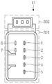
도 3 은 본 발명의 실시예에서 스위치에 구비되는 단자들의 구성을 나타내는 도면으로서, 각 스위치(11)의 후면 등에 구비되는 기능단자(301)와 인식단자(302)를 예시한 것이며, 스위치가 인스트루먼트 패널 등에 구비된 슬롯에 삽입되었을 때 슬롯의 차량 측 단자와 접속되는 스위치의 단자들을 예시한 것이다.3 is a view showing the configuration of the terminals provided in the switch in the embodiment of the present invention, illustrating the
본 발명에서 스위치들은 각각 동일한 크기와 구조를 가지며, 이에 스위치들이 다수 슬롯 중 임의의 슬롯에 삽입되더라도 스위치로서의 기능 수행 및 사용이 가능하다.In the present invention, the switches each have the same size and structure, and thus, even if the switches are inserted into any of a plurality of slots, functions of the switches can be performed and used.
도 3에 도시된 바와 같이, 각 스위치(11)의 후면에는 슬롯에 삽입될 때 슬롯 내 차량 측 단자와 전기적으로 접속되는 기능단자(301)가 구비되는데, 예로서 스위치 VCC 단자(1), 접지단자(2), 스위치 선택 단자(3), 야간조명 (+)/(-) 단자(4,5), 동작조명 (+)/(-) 단자(6,7) 등을 포함할 수 있다.As shown in FIG. 3, the rear of each
이들 기능단자는 동작조명과 야간조명으로 사용되는 LED가 내장된 스위치에서 LED의 점등 및 소등, 그리고 스위치의 온/오프 조작상태에 따른 신호를 출력하기 위한 관련 단자로서, 각 스위치에 동일한 위치 및 구조로 구비된다.These functional terminals are related terminals for outputting signals according to the ON / OFF operation status of the switch on / off of the LED in the switch with the built-in LED used for operation lighting and night lighting. It is provided with.
이와 더불어, 본 발명에서는 스위치의 슬롯 삽입과 동시에 스위치의 종류 및 용도를 직관적으로 제어모듈이 인식할 수 있게 해주는 인식단자(302)가 추가로 구비되고, 상기 인식단자(302) 역시 슬롯 내에 별도로 추가 구비되는 차량측 대응단자와 전기적으로 접속된다.In addition, in the present invention, a
이때, 인식단자(302)는 3핀(Ra,Rb,GND)으로 구성되며, ABS(Anti-lock Brake System), TPMS(Tire Pressure Monitoring System), LDWS(Lane Departure Warning System) 등과 같이 통신으로 제어를 수행하는 시스템에 통신형 스위치로서 사용되는 경우에 동작하는 것이 바람직하다.At this time, the
본 발명에서 인식단자(302)의 위치 및 구조 역시 다른 단자들과 마찬가지로 각 스위치(11)에 동일하게 구비되며, 인식단자(302)가 접속되는 차량측 대응단자(이하, 대응단자로 약칭함)의 위치 및 구조도 각 슬롯에 모두 동일하게 구비된다.In the present invention, the position and structure of the
이에 임의의 스위치가 슬롯에 삽입되더라도, 그리고 임의의 슬롯에 스위치가 삽입되더라도 스위치(11)의 인식단자(302)와 슬롯의 차량 측 대응단자가 접속될 수 있게 되어 있다.Thus, even if an arbitrary switch is inserted into the slot, and even if the switch is inserted into the arbitrary slot, the
상술한 바와 같이, 스위치(11)는 통신형 단자로 동작할 수도 있고, 인식단자(302)가 동작하지 않는 경우에 비통신형 스위치로 동작할 수도 있다. 즉, 스위치(11)는 통신형 스위치는 물론 비통신형 스위치로 사용될 수 있는 공용 스위치이다.As described above, the
도 4는 본 발명의 실시예에 따른 스위치 인식 장치의 구성을 나타내는 회로도로서, 이는 스위치(11)가 임의의 슬롯에 삽입되더라도 제어모듈(20)이 그 스위치의 종류를 인식할 수 있게 해주는 회로 구성을 보여주고 있다.4 is a circuit diagram showing the configuration of a switch recognition apparatus according to an embodiment of the present invention, which allows the
도 4에 도시된 바와 같이, 스위치(11)가 슬롯에 삽입되면 스위치의 인식단자(302)가 제어모듈과 연결된다.As shown in FIG. 4, when the
또한 스위치(11) 내에는 소정의 저항값을 갖는 저항(Ra,Rb)이 구비되며, 이 저항(Ra,Rb)은 풀다운 저항(pull-down resistor)이 될 수 있다. 2개의 저항(Ra,Rb)을 사용하는 경우에 대해 설명했지만, 1개의 저항을 사용해도 무방하다.In addition, the
상기 풀다운 저항(Ra,Rb)은 스위치마다 미리 정해진 고유의 저항값을 가지는데, 각 스위치의 풀다운 저항은 스위치 종류마다 상이한 저항값을 갖는 것이 사용된다.The pull-down resistors Ra and Rb have a predetermined resistance value predetermined for each switch, and a pull-down resistor of each switch has a different resistance value for each switch type.
또한 상기 풀다운 저항은 PCB 실장 방법, 인서트 몰드 방법, 가변 저항 이용 방법 중 선택된 어느 하나의 방법으로 스위치(11) 내에 설치될 수 있다.In addition, the pull-down resistor may be installed in the
먼저, PCB 실장 방법은 스위치에 내장되는 PCB에 소정의 저항값을 갖는 풀다운 저항을 실장하는 방법으로서, PCB(Printed Circuit Board)에 부품을 실장하는 SMT(Surface Mount Technology) 공정이나 조립 단계에서 PCB에 해당 스위치에 적용될 풀다운 저항을 실장한 뒤, 스위치 조립 단계에서 상기 PCB를 스위치 내에 조립함으로써, 풀다운 저항을 스위치에 구비할 수 있게 된다.First, a PCB mounting method is a method of mounting a pull-down resistor having a predetermined resistance value on a PCB embedded in a switch, and is applied to a PCB in an SMT (Surface Mount Technology) process or an assembly step in which components are mounted on a printed circuit board (PCB). After mounting the pull-down resistor to be applied to the switch, assembling the PCB in the switch in the switch assembly step, it is possible to include a pull-down resistor in the switch.
이러한 PCB 실장 방법에서는, 스위치 종류에 따라 풀다운 저항을 구분하여 실장한 여러 종류의 PCB를 제작한 다음, 스위치 조립 단계에서 종류에 맞는 풀다운 저항을 실장한 PCB를 선택, 사용하여 스위치를 조립하게 된다.In this PCB mounting method, a plurality of PCBs are fabricated by dividing pulldown resistors according to the switch type, and then the switches are assembled by selecting and using a PCB mounted with pulldown resistors according to the type.
간단히 원하는 저항값의 풀다운 저항을 사용한 PCB를 선택하여 스위치에 조립하는 것이므로 별도의 추가 공정이 필요 없다.Simply select the PCB using the pull-down resistor of the desired resistance value and assemble it to the switch, so no additional process is required.
인서트 몰드 방법에서는, 상기와 같이 PCB에 저항을 실장하는 대신, 스위치 몸체 등을 금형 몰드(mold)로 성형 제작한 뒤 PCB 등의 관련 부품들을 조립하여 스위치 패키지를 구성하고 나면, 즉 스위치의 조립을 완료하면, 스위치의 종류에 따라 소정의 저항값을 갖는 풀다운 저항을 스위치 몸체의 정해진 위치에 솔더링(soldering)하여 부착하는 방식이다.In the insert mold method, instead of mounting a resistor on the PCB as described above, after forming the switch body and the like into a mold mold and assembling related parts such as the PCB to form a switch package, that is, assembling the switch is performed. Upon completion, a pull-down resistor having a predetermined resistance value is soldered to a predetermined position of the switch body according to the type of the switch.
이때, 풀다운 저항이 솔더링만으로 인식단자와 접지단자 사이에 연결될 수 있도록 상기 인식단자와 접지단자에 각각 연결된 별도 단자를 스위치 몸체 외부에서 솔더링 가능하게 외부 연장하여 구비하고, 이후 양측 단자에 풀다운 저항의 양단을 간단히 솔더링하여 접속하게 된다.In this case, a separate terminal connected to each of the recognition terminal and the ground terminal can be externally extended from the outside of the switch body so that the pull-down resistor can be connected between the recognition terminal and the ground terminal only by soldering, and then both ends of the pull-down resistor are provided at both terminals. It is simply soldered and connected.
이러한 인서트 몰드 방식은, 스위치 몸체나 PCB 등 각종 부품을 스위치 종류에 상관없이 동일하게 제작한 뒤 선 조립 후 필요한 저항값의 풀다운 저항을 간단히 선택, 조립하는 방식이므로, 소정 저항값의 풀다운 저항을 스위치에 구성하는 것이 용이한 이점을 갖는다.Since the insert mold method is to make various parts such as switch body and PCB regardless of the switch type, and then simply select and assemble pull-down resistors of required resistance values after pre-assembly, switch pull-down resistors of predetermined resistance values are switched. It has the advantage of being easy to configure.
종류별 PCB를 제작하는 방식에 비해 PCB 단위의 사양 관리가 필요 없으며, 스위치 완 조립 후 저항을 부착하므로 차량의 모델 및 차종 등에 관계없이 동일하게 스위치들을 제작한 뒤 풀다운 저항을 선택 조립할 수 있는바, 관리 측면(스위치 종류별 소자 단위의 관리 필요)이나 저항값 변경 등 각종 리워크 작업 측면에서 유리해지는 이점이 있다.Compared to the method of manufacturing PCB by type, there is no need to manage the specification of the PCB unit.As the resistor is attached after the assembly of the switch, the pulldown resistor can be selected and assembled regardless of the vehicle model and vehicle type. This is advantageous in terms of various rework operations, such as the side (requires management of device units for each switch type) and the change of the resistance value.
또한 가변 저항 이용 방법에서는 풀다운 저항으로서 가변 저항을 PCB에 실장한 뒤 스위치 선택 단계에서 가변 저항의 저항값을 외부에서 설정한 후 고정시키는 방식으로서, 이때 풀다운 저항은 소형 모터를 갖는 모듈 형태의 저항기, 즉 모터를 사용하여 저항값을 가변시키는 전동가변저항기가 될 수 있다.In addition, in the method of using a variable resistor, a variable resistor is mounted on a PCB as a pull-down resistor, and then the resistance value of the variable resistor is externally set and fixed at the switch selection step. In this case, the pull-down resistor is a module-type resistor having a small motor, That is, it can be an electric variable resistor that varies the resistance value using a motor.
즉, 동일 사양으로 스위치를 제작한 뒤 필요한 저항값에 따라 모터를 회전시켜 풀다운 저항의 저항값 및 스위치 종류가 선택되도록 하는 것이며, 저항값을 선택한 후 고정하는 록 핀(lock pin) 등이 사용될 수 있다.In other words, after making the switch with the same specification, the motor rotates according to the required resistance value so that the resistance value and the switch type of the pull-down resistor can be selected, and a lock pin for selecting and fixing the resistance value can be used. have.
이러한 가변 저항 이용 방법에서는 자동화 공정을 통해 신뢰성을 높일 수 있는 이점이 있고, 더불어 저항값 설정 및 양품 검사를 동시에 진행할 수 있는 이점이 있다.In this method of using variable resistors, there is an advantage that the reliability can be increased through an automated process, and there is an advantage in that the resistance value setting and the quality inspection can be simultaneously performed.
이와 같이 공정상의 관리 용이성 또는 부품 공용화에 따른 관리 편의성, 원가 절감 등을 종합적으로 고려하여 풀다운 저항의 설치 방법, 저항값 설정 방법을 위의 세 가지 방법 중 어느 하나로 실시할 수 있다.In this way, the installation method of the pull-down resistor and the resistance value setting method may be performed by any one of the above three methods in consideration of the ease of management in the process or the management convenience due to the common use of components and cost reduction.
한편, 본 발명의 스위치 인식 장치는 각 슬롯에 대해 삽입된 스위치(11)를 판별하는 제어모듈(20)을 포함하며, 상기 제어모듈(20)은 슬롯에 삽입된 스위치(11)의 인식단자(302)와 전기적으로 연결되어 스위치 내 풀다운 저항의 저항값에 따른 스위치별 고유 식별 신호(ADC값)를 출력하는 AD 컨버터(도면에는 도시되어 있지 않음)를 포함할 수도 있다.On the other hand, the switch recognition device of the present invention includes a
바람직한 실시예에서, 상기 AD 컨버터는 슬롯별로 구비되는 복수의 입력채널을 가지며, 각 입력채널이 슬롯의 대응단자에 와이어링(입력단회로)을 통해 1:1로 연결되는 구조를 갖는다.In a preferred embodiment, the AD converter has a plurality of input channels provided for each slot, and each input channel has a structure in which the respective input channels are connected 1: 1 to each corresponding terminal of the slot through a wiring (input terminal circuit).
또한 AD 컨버터의 각 입력채널과 각 슬롯의 대응단자 사이를 연결하는 각각의 입력단회로에는 전원입력회로가 연결되고, 입력단회로에 연결된 각각의 전원입력회로에는 풀업 저항(pull-up resistor)이 설치된다.In addition, a power input circuit is connected to each input terminal circuit connecting each input channel of the AD converter and a corresponding terminal of each slot, and a pull-up resistor is installed in each power input circuit connected to the input terminal circuit. .
여기서, 각 풀업 저항은 동일한 저항값(일예로 10K)을 가지는 것이 사용될 수 있다.Here, each pull-up resistor may have the same resistance value (for example, 10K).
이에 따라, 임의의 슬롯에 스위치(11)가 삽입되어 스위치의 인식단자(302)와 슬롯의 대응단자가 접속되고 나면, 스위치 내 풀다운 저항이 인식단자와 슬롯의 대응단자, 입력단회로를 통해 AD 컨버터의 입력채널과 연결되게 된다.Accordingly, when the
이때, AD 컨버터는 입력단회로에 걸리는 전압값에 따라 각 슬롯에 삽입된 스위치별로 스위치 종류 식별이 가능하도록 해주는 고유의 전기적 신호, 즉 스위치별 고유 식별 신호(후술하는 ADC값)를 출력하게 된다.At this time, the AD converter outputs a unique electrical signal that enables switch type identification for each switch inserted into each slot, that is, a unique identification signal for each switch (the ADC value described later) according to the voltage value applied to the input end circuit.
상기 AD 컨버터는 스위치별 고유 식별 신호를 출력하는 각 출력채널이 제어모듈(20) 내 제어부(21)에 와이어링 연결되고, 제어부(21)가 AD 컨버터에서 출력되는 고유 식별 신호로부터 스위치의 종류를 판별하게 된다.In the AD converter, each output channel for outputting a unique identification signal for each switch is connected to the
스위치별 기 설정된 저항값을 갖는 저항이 풀다운으로 구성된 특정의 스위치가 임의의 슬롯에 삽입되면, AD 컨버터의 입력채널에 연결된 각 라인의 저항이 풀업으로 구성되어 있으므로, 상기 스위치가 접속된 라인에는 풀다운 저항과 풀업 저항에 의한 전압 분배에 의해 특정 전압값이 걸리게 된다.When a specific switch composed of pull-downs having a predetermined resistance value for each switch is inserted into an arbitrary slot, since the resistance of each line connected to the input channel of the AD converter is configured as a pull-up, the line to which the switch is connected is pulled down. The voltage distribution by the resistor and the pull-up resistor takes a certain voltage value.
이 전압값은 AD 컨버터에 의해 소정의 ADC값(디지털 신호값), 즉 스위치별 고유 식별신호로 변환되며, 결국 AD 컨버터로부터 출력되는 고유 식별 신호를 제어모듈(20) 내 제어부(21)가 입력받아 각 슬롯별로 스위치의 종류를 인식하게 된다.The voltage value is converted into a predetermined ADC value (digital signal value), that is, a unique identification signal for each switch, by the AD converter, and the
도 5는 본 발명의 실시예에서 ADC값에 따른 스위치 설정의 예를 테이블로 나타낸 도면으로서, 10 비트(bit)의 AD 컨버터를 갖는 제어모듈에서 스위치의 종류별로 기 설정되는 전압값 및 ADC값 범위를 예시한 것이다. FIG. 5 is a table showing examples of switch settings according to ADC values in an embodiment of the present invention. In the control module having a 10-bit AD converter, voltage values and ADC value ranges preset for each switch type are shown in FIG. It is an example.
이에 나타낸 바와 같이, 미사용 슬롯의 경우 풀다운 저항이 있는 스위치의 인식단자와 연결되지 않으므로 5V(4.88V ~ 5V 범위)가 AD 컨버터의 입력채널에 입력되고, 이에 AD 컨버터가 전압값에 따른 ADC값을 출력하면 제어부가 이를 입력받아 ADC값이 기 설정 범위(1000 ~ 1023 범위) 내에 있음을 확인하여 스위치의 미사용으로 인식하게 된다.As shown in the figure, since unused slots are not connected to the recognition terminal of the switch with a pull-down resistor, 5V (4.88V to 5V range) is input to the input channel of the AD converter, and the AD converter converts the ADC value according to the voltage value. When the controller outputs it, the controller checks that the ADC value is within the preset range (1000 to 1023 range) and recognizes that the switch is not in use.
반면, 스위치가 삽입되어 접속된 슬롯의 경우 스위치별 각기 설정된 풀다운 저항의 저항값에 의해 AD 컨버터가 스위치 고유 식별 신호로 특정 ADC값을 출력하는바, 제어부가 ADC값이 기 설정 범위(각 스위치 종류별로 설정되는 범위) 내에 있음을 확인하여 스위치의 종류를 인식하게 된다.On the other hand, in the case of a slot where a switch is inserted and connected, the AD converter outputs a specific ADC value as a switch unique identification signal by the resistance value of the pull-down resistor set for each switch. The type of the switch is recognized.
또한 각 스위치의 특정 ADC값으로 설정 범위 밖의 값이 검출되면 제어부는 이를 에러(error) 처리하게 된다.In addition, if a value outside the setting range is detected as a specific ADC value of each switch, the control unit processes an error.
이상으로 본 발명에 따른 스위치 인식 장치의 구성에 대해 상술하였으며, 위에서 전압 분배를 위해 스위치의 저항이 풀다운 저항으로, 제어모듈의 저항이 전원입력회로의 풀업 저항으로 구성됨을 설명하였으나, 본 발명에서 반대의 구성, 즉 스위치에 설치되는 저항이 전원과 연결되는 풀업 저항으로, 제어모듈에 설치되는 저항이 접지로 연결되는 풀다운 저항으로 구성될 수도 있다.As described above, the configuration of the switch recognition device according to the present invention has been described above, but the resistor of the switch is configured as a pull-down resistor for the voltage distribution, and the resistor of the control module is configured as the pull-up resistor of the power input circuit. In other words, the resistor installed in the switch may be configured as a pull-up resistor connected to the power supply, and the resistor installed in the control module may be configured as a pull-down resistor connected to the ground.
또한 본 발명은 스위치 내 저항의 저항값에 따라 상술한 전압 분배 방식 외에 ADC 채널에 입력되는 신호가 전류 변화 방식으로 ADC값의 변화를 주어, 제어부가 스위치별로 기 설정된 범위에서 ADC값을 검출할 경우 검출값에 따라 스위치를 식별하도록 하는 방식이 될 수도 있다. In addition, the present invention, in addition to the above-described voltage division method according to the resistance value of the switch in the switch, the signal input to the ADC channel to change the ADC value in the current change method, when the control unit detects the ADC value in the preset range for each switch The switch may be identified according to the detected value.
또한 배선을 간소화하기 위해 복수의 스위치들이 그룹으로 구성되어 있는 스위치 모듈에 따라 위치상으로 나누어 제어모듈이 구성될 수 있고, 각각의 제어모듈이 LIN 통신 또는 CAN 통신 등의 기타 다양한 통신 방식으로 스위치의 상태 정보를 상호 전달하도록 구성될 수 있다.In addition, in order to simplify wiring, a control module may be divided into positions according to a switch module having a plurality of switches grouped together, and each control module may be configured in various communication methods such as LIN communication or CAN communication. It can be configured to communicate state information to each other.
또한 하나의 통합된 제어모듈에서 모든 스위치의 입력을 받아 스위치 종류 인식 등을 수행하도록 구성될 수도 잇다.In addition, a single integrated control module may be configured to receive switch inputs and perform switch type recognition.
이와 같이 하여, 본 발명에서는 스위치를 임의의 슬롯에 설치하더라도 제어모듈이 스위치의 종류를 인식할 수 있고, 결국 원하는 위치에 스위치를 자유롭게 배치할 수 있게 된다.In this way, in the present invention, even if the switch is installed in any slot, the control module can recognize the type of switch, it is possible to freely arrange the switch in the desired position.
특히 간단히 슬롯에 스위치만 꽂아주게 되면 제어모듈이 스위치의 종류를 구분해서 식별할 수 있으므로 스위치의 자유로운 배치가 가능해져 사용자 편의대로 스위치들을 배열할 수 있고, 사용 빈도에 따라 조작성이 좋은 위치에 순서대로 스위치를 배치하는 것이 가능하다.Particularly, simply plugging the switch into the slot allows the control module to identify the type of switch so that the switch can be arranged freely, so that the switches can be arranged at the user's convenience. It is possible to place a switch.
궁극적으로는 운전자가 손쉽게 조작할 수 있는 근접된 위치에 스위치를 자유롭게 배열할 수 있으므로 조작의 편의성 증대, 운전 부주의로 인한 교통사고 방지, 운전 편의성 증대 등의 효과가 있게 된다.Ultimately, the switch can be freely arranged in a close position where the driver can easily operate, thereby increasing convenience of operation, preventing traffic accidents due to inadvertent driving, and increasing driving convenience.
또한 레이아웃 자유도의 증대로 디자인 측면에서 매우 유리해지며, 사양 관리가 용이해지고, 조립 작업성이 증대되는 등의 이점이 있게 된다. In addition, the increase in the degree of freedom of layout is very advantageous in terms of design, it is easy to manage the specifications, there is an advantage such as increased assembly workability.
또한 차량의 모델이나 차종에 따라 사용 스위치의 개수에 맞추어 슬롯을 구비하게 되면 종래와 같이 다수의 블랭킹 커버나 플러그를 사용하지 않아도 되며, 도 6에 나타낸 바와 같이 남는 공간을 포켓 등으로 활용이 가능해지므로 공간 활용도가 증대될 수 있다.In addition, if a slot is provided according to the number of switches used according to the model and vehicle of the vehicle, it is not necessary to use a plurality of blanking covers or plugs as in the prior art, and as shown in FIG. 6, the remaining space can be utilized as a pocket. Space utilization can be increased.
이상에서 설명한 본 발명은, 본 발명이 속하는 기술 분야에서 통상의 지식을 가진 자에게 있어 본 발명의 기술적 사상을 벗어나지 않는 범위 내에서 여러 가지 치환, 변형 및 변경이 가능하므로 전술한 실시예 및 첨부된 도면에 의해 한정되는 것이 아니다.
It will be apparent to those skilled in the art that various modifications and variations can be made in the present invention without departing from the spirit or scope of the invention. The present invention is not limited to the drawings.
11 ~ 14 : 스위치 302 : 인식단자
18 : 블랭킹 커버(또는 플러그) 20 : 제어모듈
21 : 제어부11 ~ 14: Switch 302: Recognition terminal
18: blanking cover (or plug) 20: control module
21:
Claims (11)
접지단자와 2개의 저항단자로 이루어져 상기 스위치에 구비되며, 슬롯에 스위치가 삽입될 때 슬롯 내 대응단자에 접속되는 인식단자;
상기 스위치에서 인식단자에 연결되고 스위치별로 설정된 상이한 저항값을 갖는 저항;
상기 슬롯 내 대응단자에 연결된 입력단회로를 통해 스위치 내 상기 저항의 저항값에 따른 신호를 입력받아 스위치의 종류를 인식하는 제어모듈
을 포함하는 차량용 스위치 인식 장치.
In the switch recognition device for recognizing the switch inserted in the slot of the vehicle,
A recognition terminal provided in the switch, comprising a ground terminal and two resistance terminals and connected to a corresponding terminal in the slot when the switch is inserted into the slot;
A resistor connected to the recognition terminal in the switch and having a different resistance value set for each switch;
The control module recognizes the type of the switch by receiving a signal according to the resistance value of the resistance in the switch through an input terminal circuit connected to the corresponding terminal in the slot
Vehicle switch recognition device comprising a.
상기 제어모듈은,
상기 입력단회로를 통해 슬롯 내 대응단자에 연결되고 상기 스위치 내 저항의 저항값에 따른 신호를 변환하여 스위치의 종류를 나타내는 ADC값을 출력하는 AD 컨버터를 더 포함하는 차량용 스위치 인식 장치.
The method of claim 1,
The control module includes:
And an AD converter connected to the corresponding terminal in the slot through the input terminal circuit and converting a signal according to the resistance value of the resistance in the switch to output an ADC value indicating the type of the switch.
상기 제어모듈은,
AD 컨버터의 입력단회로에 연결되는 저항을 더 포함하는 차량용 스위치 인식 장치.
3. The method of claim 2,
The control module includes:
Vehicle switch recognition device further comprises a resistor connected to the input terminal circuit of the AD converter.
스위치 내 저항이 접지로 연결되는 풀다운 저항이고, 상기 제어모듈의 저항이 상기 입력단회로에 연결된 전원입력회로의 풀업 저항인 것을 특징으로 하는 차량용 스위치 인식 장치.
The method of claim 3, wherein
And a resistor in the switch is a pull-down resistor connected to ground, and the resistor of the control module is a pull-up resistor of a power input circuit connected to the input terminal circuit.
상기 AD 컨버터는 복수의 입력채널을 가지며, 상기 AD 컨버터의 각 입력채널이 복수로 구비된 슬롯의 각 대응단자에 상기 입력단회로를 통해 1:1로 연결되는 것을 특징으로 하는 차량용 스위치 인식 장치.
5. The method according to any one of claims 2 to 4,
And the AD converter has a plurality of input channels, and each input channel of the AD converter is connected 1: 1 to each corresponding terminal of a slot provided with a plurality of slots through the input terminal circuit.
상기 제어모듈은,
상기 AD 컨버터에서 출력되는 ADC값으로부터 스위치의 종류를 판별하는 제어부를 더 포함하는 차량용 스위치 인식 장치.
3. The method of claim 2,
The control module includes:
And a controller for determining a type of a switch from an ADC value output from the AD converter.
상기 제어부는,
ADC값이 스위치의 종류별로 설정된 범위 이내의 값인지를 확인하여 스위치의 종류를 판별하는 것을 특징으로 하는 차량용 스위치 인식 장치.
The method according to claim 6,
The control unit,
A vehicle switch recognition device, characterized in that for determining the type of the switch by checking whether the ADC value is within the range set by the type of the switch.
상기 제어부는,
각 스위치의 종류별로 설정된 범위를 벗어나는 경우 에러 처리하도록 설정되는 것을 특징으로 하는 차량용 스위치 인식 장치.
The method of claim 7, wherein
The control unit,
The switch recognition apparatus for a vehicle, characterized in that it is set to handle an error when out of the set range for each type of switch.
상기 저항은,
스위치 내 PCB에 실장되는 것을 특징으로 하는 차량용 스위치 인식 장치.
The method of claim 1,
The resistance is,
Vehicle switch recognition device, characterized in that mounted on the PCB in the switch.
상기 저항은,
금형 몰드로 성형된 스위치 몸체에 각 부품이 조립 완료된 상태에서 상기 인식단자에 접속되도록 스위치 몸체의 정해진 위치에 솔더링하여 부착되는 것을 특징으로 하는 차량용 스위치 인식 장치.
The method of claim 1,
The resistance is,
Vehicle switch recognition device, characterized in that attached to the switch body formed by the mold in the soldered state at a predetermined position of the switch body so that each part is connected to the recognition terminal in the assembled state.
상기 저항은,
외부 조작에 따라 저항값을 가변 설정할 수 있는 가변 저항인 것을 특징으로 하는 차량용 스위치 인식 장치.The method of claim 1,
The resistance is,
A vehicle switch recognition device, characterized in that the variable resistance that can be set variable in accordance with the external operation.
Priority Applications (1)
| Application Number | Priority Date | Filing Date | Title |
|---|---|---|---|
| KR1020120116502A KR101360687B1 (en) | 2012-10-19 | 2012-10-19 | Switch identification system for vehicle |
Applications Claiming Priority (1)
| Application Number | Priority Date | Filing Date | Title |
|---|---|---|---|
| KR1020120116502A KR101360687B1 (en) | 2012-10-19 | 2012-10-19 | Switch identification system for vehicle |
Publications (1)
| Publication Number | Publication Date |
|---|---|
| KR101360687B1 true KR101360687B1 (en) | 2014-02-10 |
Family
ID=50270376
Family Applications (1)
| Application Number | Title | Priority Date | Filing Date |
|---|---|---|---|
| KR1020120116502A Active KR101360687B1 (en) | 2012-10-19 | 2012-10-19 | Switch identification system for vehicle |
Country Status (1)
| Country | Link |
|---|---|
| KR (1) | KR101360687B1 (en) |
Cited By (1)
| Publication number | Priority date | Publication date | Assignee | Title |
|---|---|---|---|---|
| KR101952188B1 (en) | 2017-08-21 | 2019-02-27 | 타타대우상용차(주) | Switch identification apparatus for vehicle |
Citations (3)
| Publication number | Priority date | Publication date | Assignee | Title |
|---|---|---|---|---|
| KR20040013790A (en) * | 2002-08-08 | 2004-02-14 | 엘지전자 주식회사 | Specific resistance switch apparatus |
| KR20040047986A (en) * | 2002-12-02 | 2004-06-07 | 현대자동차주식회사 | Remote control switch circuit for steering wheel |
| JP2008276983A (en) | 2007-04-25 | 2008-11-13 | Denso Corp | Switch device |
-
2012
- 2012-10-19 KR KR1020120116502A patent/KR101360687B1/en active Active
Patent Citations (3)
| Publication number | Priority date | Publication date | Assignee | Title |
|---|---|---|---|---|
| KR20040013790A (en) * | 2002-08-08 | 2004-02-14 | 엘지전자 주식회사 | Specific resistance switch apparatus |
| KR20040047986A (en) * | 2002-12-02 | 2004-06-07 | 현대자동차주식회사 | Remote control switch circuit for steering wheel |
| JP2008276983A (en) | 2007-04-25 | 2008-11-13 | Denso Corp | Switch device |
Cited By (1)
| Publication number | Priority date | Publication date | Assignee | Title |
|---|---|---|---|---|
| KR101952188B1 (en) | 2017-08-21 | 2019-02-27 | 타타대우상용차(주) | Switch identification apparatus for vehicle |
Similar Documents
| Publication | Publication Date | Title |
|---|---|---|
| KR101209799B1 (en) | Switch identification system for vehicle | |
| US6441510B1 (en) | Reconfigurable modular instrument cluster arrangement | |
| US5742130A (en) | Intelligent lamp or intelligent contact terminal for a lamp | |
| US20070228826A1 (en) | Modular, extensible electrical and communication systems, methods, and devices | |
| US10124721B2 (en) | System to augment automotive factory lights with warning light function | |
| US20120283914A1 (en) | Vehicle steering wheel control system having integrated electronic control unit | |
| CN110741606B (en) | Programmable plug | |
| US6511342B1 (en) | Modular instrument panel system having a flat flexible bus | |
| US9530584B2 (en) | Common switch device for vehicle | |
| JPH03176902A (en) | Controller for electric devices of automobile | |
| EP2381229A2 (en) | Photo detection device | |
| US10562473B2 (en) | Electric current distribution system for a vehicle | |
| CN110994287A (en) | Wire harness | |
| KR101360687B1 (en) | Switch identification system for vehicle | |
| WO2013046700A1 (en) | Vehicle data setting system and output setting method thereof | |
| JP2016123186A (en) | On-vehicle wire harness | |
| CN107074151A (en) | Electronic circuit for blind spot monitoring display device | |
| KR101282623B1 (en) | Vehicle switch recognition device and method | |
| JP6806428B2 (en) | In-vehicle control system | |
| US20220388444A1 (en) | Headlamp for a vehicle | |
| US8903566B2 (en) | Parity on data link switches | |
| JP2016203731A (en) | Connecting member and vehicle network system | |
| JP6793490B2 (en) | Automotive connectors, connector boxes and vehicle network systems | |
| US20120091926A1 (en) | Electronic speed controller apparatus with signal dividing port device and control method thereof | |
| JP2016213634A (en) | ID identification setting method in vehicle network system |
Legal Events
| Date | Code | Title | Description |
|---|---|---|---|
| A201 | Request for examination | ||
| PA0109 | Patent application |
St.27 status event code: A-0-1-A10-A12-nap-PA0109 |
|
| PA0201 | Request for examination |
St.27 status event code: A-1-2-D10-D11-exm-PA0201 |
|
| PN2301 | Change of applicant |
St.27 status event code: A-3-3-R10-R13-asn-PN2301 St.27 status event code: A-3-3-R10-R11-asn-PN2301 |
|
| PN2301 | Change of applicant |
St.27 status event code: A-3-3-R10-R13-asn-PN2301 St.27 status event code: A-3-3-R10-R11-asn-PN2301 |
|
| PN2301 | Change of applicant |
St.27 status event code: A-3-3-R10-R13-asn-PN2301 St.27 status event code: A-3-3-R10-R11-asn-PN2301 |
|
| D13-X000 | Search requested |
St.27 status event code: A-1-2-D10-D13-srh-X000 |
|
| D14-X000 | Search report completed |
St.27 status event code: A-1-2-D10-D14-srh-X000 |
|
| E701 | Decision to grant or registration of patent right | ||
| PE0701 | Decision of registration |
St.27 status event code: A-1-2-D10-D22-exm-PE0701 |
|
| GRNT | Written decision to grant | ||
| PR0701 | Registration of establishment |
St.27 status event code: A-2-4-F10-F11-exm-PR0701 |
|
| PR1002 | Payment of registration fee |
St.27 status event code: A-2-2-U10-U11-oth-PR1002 Fee payment year number: 1 |
|
| PG1601 | Publication of registration |
St.27 status event code: A-4-4-Q10-Q13-nap-PG1601 |
|
| R18-X000 | Changes to party contact information recorded |
St.27 status event code: A-5-5-R10-R18-oth-X000 |
|
| P22-X000 | Classification modified |
St.27 status event code: A-4-4-P10-P22-nap-X000 |
|
| PN2301 | Change of applicant |
St.27 status event code: A-5-5-R10-R13-asn-PN2301 St.27 status event code: A-5-5-R10-R11-asn-PN2301 |
|
| PR1001 | Payment of annual fee |
St.27 status event code: A-4-4-U10-U11-oth-PR1001 Fee payment year number: 4 |
|
| R18-X000 | Changes to party contact information recorded |
St.27 status event code: A-5-5-R10-R18-oth-X000 |
|
| FPAY | Annual fee payment |
Payment date: 20180130 Year of fee payment: 5 |
|
| PR1001 | Payment of annual fee |
St.27 status event code: A-4-4-U10-U11-oth-PR1001 Fee payment year number: 5 |
|
| PN2301 | Change of applicant |
St.27 status event code: A-5-5-R10-R11-asn-PN2301 |
|
| PN2301 | Change of applicant |
St.27 status event code: A-5-5-R10-R14-asn-PN2301 |
|
| PN2301 | Change of applicant |
St.27 status event code: A-5-5-R10-R13-asn-PN2301 St.27 status event code: A-5-5-R10-R11-asn-PN2301 |
|
| FPAY | Annual fee payment |
Payment date: 20190130 Year of fee payment: 6 |
|
| PR1001 | Payment of annual fee |
St.27 status event code: A-4-4-U10-U11-oth-PR1001 Fee payment year number: 6 |
|
| R18-X000 | Changes to party contact information recorded |
St.27 status event code: A-5-5-R10-R18-oth-X000 |
|
| R18-X000 | Changes to party contact information recorded |
St.27 status event code: A-5-5-R10-R18-oth-X000 |
|
| R18-X000 | Changes to party contact information recorded |
St.27 status event code: A-5-5-R10-R18-oth-X000 |
|
| FPAY | Annual fee payment |
Payment date: 20191219 Year of fee payment: 7 |
|
| PR1001 | Payment of annual fee |
St.27 status event code: A-4-4-U10-U11-oth-PR1001 Fee payment year number: 7 |
|
| PR1001 | Payment of annual fee |
St.27 status event code: A-4-4-U10-U11-oth-PR1001 Fee payment year number: 8 |
|
| PN2301 | Change of applicant |
St.27 status event code: A-5-5-R10-R13-asn-PN2301 St.27 status event code: A-5-5-R10-R11-asn-PN2301 |
|
| PR1001 | Payment of annual fee |
St.27 status event code: A-4-4-U10-U11-oth-PR1001 Fee payment year number: 9 |
|
| PR1001 | Payment of annual fee |
St.27 status event code: A-4-4-U10-U11-oth-PR1001 Fee payment year number: 10 |
|
| PR1001 | Payment of annual fee |
St.27 status event code: A-4-4-U10-U11-oth-PR1001 Fee payment year number: 11 |
|
| PR1001 | Payment of annual fee |
St.27 status event code: A-4-4-U10-U11-oth-PR1001 Fee payment year number: 12 |
|
| U11 | Full renewal or maintenance fee paid |
Free format text: ST27 STATUS EVENT CODE: A-4-4-U10-U11-OTH-PR1001 (AS PROVIDED BY THE NATIONAL OFFICE) Year of fee payment: 12 |