KR101314588B1 - Method and apparatus for producing map of artificial mark, method and apparatus for measuring position of mobile object by using same - Google Patents
Method and apparatus for producing map of artificial mark, method and apparatus for measuring position of mobile object by using same Download PDFInfo
- Publication number
- KR101314588B1 KR101314588B1 KR1020090128336A KR20090128336A KR101314588B1 KR 101314588 B1 KR101314588 B1 KR 101314588B1 KR 1020090128336 A KR1020090128336 A KR 1020090128336A KR 20090128336 A KR20090128336 A KR 20090128336A KR 101314588 B1 KR101314588 B1 KR 101314588B1
- Authority
- KR
- South Korea
- Prior art keywords
- artificial marker
- artificial
- marker
- moving object
- information
- Prior art date
- Legal status (The legal status is an assumption and is not a legal conclusion. Google has not performed a legal analysis and makes no representation as to the accuracy of the status listed.)
- Active
Links
Images


Classifications
-
- G—PHYSICS
- G01—MEASURING; TESTING
- G01C—MEASURING DISTANCES, LEVELS OR BEARINGS; SURVEYING; NAVIGATION; GYROSCOPIC INSTRUMENTS; PHOTOGRAMMETRY OR VIDEOGRAMMETRY
- G01C15/00—Surveying instruments or accessories not provided for in groups G01C1/00 - G01C13/00
-
- G—PHYSICS
- G01—MEASURING; TESTING
- G01C—MEASURING DISTANCES, LEVELS OR BEARINGS; SURVEYING; NAVIGATION; GYROSCOPIC INSTRUMENTS; PHOTOGRAMMETRY OR VIDEOGRAMMETRY
- G01C15/00—Surveying instruments or accessories not provided for in groups G01C1/00 - G01C13/00
- G01C15/02—Means for marking measuring points
- G01C15/06—Surveyors' staffs; Movable markers
-
- G—PHYSICS
- G05—CONTROLLING; REGULATING
- G05D—SYSTEMS FOR CONTROLLING OR REGULATING NON-ELECTRIC VARIABLES
- G05D1/00—Control of position, course, altitude or attitude of land, water, air or space vehicles, e.g. using automatic pilots
- G05D1/02—Control of position or course in two dimensions
- G05D1/021—Control of position or course in two dimensions specially adapted to land vehicles
- G05D1/0231—Control of position or course in two dimensions specially adapted to land vehicles using optical position detecting means
- G05D1/0246—Control of position or course in two dimensions specially adapted to land vehicles using optical position detecting means using a video camera in combination with image processing means
-
- G—PHYSICS
- G05—CONTROLLING; REGULATING
- G05D—SYSTEMS FOR CONTROLLING OR REGULATING NON-ELECTRIC VARIABLES
- G05D1/00—Control of position, course, altitude or attitude of land, water, air or space vehicles, e.g. using automatic pilots
- G05D1/02—Control of position or course in two dimensions
- G05D1/021—Control of position or course in two dimensions specially adapted to land vehicles
- G05D1/0268—Control of position or course in two dimensions specially adapted to land vehicles using internal positioning means
- G05D1/0274—Control of position or course in two dimensions specially adapted to land vehicles using internal positioning means using mapping information stored in a memory device
-
- G—PHYSICS
- G05—CONTROLLING; REGULATING
- G05D—SYSTEMS FOR CONTROLLING OR REGULATING NON-ELECTRIC VARIABLES
- G05D1/00—Control of position, course, altitude or attitude of land, water, air or space vehicles, e.g. using automatic pilots
- G05D1/20—Control system inputs
- G05D1/24—Arrangements for determining position or orientation
-
- G—PHYSICS
- G09—EDUCATION; CRYPTOGRAPHY; DISPLAY; ADVERTISING; SEALS
- G09B—EDUCATIONAL OR DEMONSTRATION APPLIANCES; APPLIANCES FOR TEACHING, OR COMMUNICATING WITH, THE BLIND, DEAF OR MUTE; MODELS; PLANETARIA; GLOBES; MAPS; DIAGRAMS
- G09B29/00—Maps; Plans; Charts; Diagrams, e.g. route diagram
- G09B29/003—Maps
- G09B29/004—Map manufacture or repair; Tear or ink or water resistant maps; Long-life maps
-
- G—PHYSICS
- G05—CONTROLLING; REGULATING
- G05D—SYSTEMS FOR CONTROLLING OR REGULATING NON-ELECTRIC VARIABLES
- G05D1/00—Control of position, course, altitude or attitude of land, water, air or space vehicles, e.g. using automatic pilots
- G05D1/02—Control of position or course in two dimensions
- G05D1/021—Control of position or course in two dimensions specially adapted to land vehicles
- G05D1/0231—Control of position or course in two dimensions specially adapted to land vehicles using optical position detecting means
- G05D1/0238—Control of position or course in two dimensions specially adapted to land vehicles using optical position detecting means using obstacle or wall sensors
- G05D1/024—Control of position or course in two dimensions specially adapted to land vehicles using optical position detecting means using obstacle or wall sensors in combination with a laser
-
- G—PHYSICS
- G05—CONTROLLING; REGULATING
- G05D—SYSTEMS FOR CONTROLLING OR REGULATING NON-ELECTRIC VARIABLES
- G05D1/00—Control of position, course, altitude or attitude of land, water, air or space vehicles, e.g. using automatic pilots
- G05D1/02—Control of position or course in two dimensions
- G05D1/021—Control of position or course in two dimensions specially adapted to land vehicles
- G05D1/0268—Control of position or course in two dimensions specially adapted to land vehicles using internal positioning means
- G05D1/0272—Control of position or course in two dimensions specially adapted to land vehicles using internal positioning means comprising means for registering the travel distance, e.g. revolutions of wheels
-
- G—PHYSICS
- G05—CONTROLLING; REGULATING
- G05D—SYSTEMS FOR CONTROLLING OR REGULATING NON-ELECTRIC VARIABLES
- G05D2111/00—Details of signals used for control of position, course, altitude or attitude of land, water, air or space vehicles
- G05D2111/10—Optical signals
-
- G—PHYSICS
- G05—CONTROLLING; REGULATING
- G05D—SYSTEMS FOR CONTROLLING OR REGULATING NON-ELECTRIC VARIABLES
- G05D2111/00—Details of signals used for control of position, course, altitude or attitude of land, water, air or space vehicles
- G05D2111/50—Internal signals, i.e. from sensors located in the vehicle, e.g. from compasses or angular sensors
Landscapes
- Engineering & Computer Science (AREA)
- Physics & Mathematics (AREA)
- Radar, Positioning & Navigation (AREA)
- General Physics & Mathematics (AREA)
- Remote Sensing (AREA)
- Automation & Control Theory (AREA)
- Aviation & Aerospace Engineering (AREA)
- Computer Vision & Pattern Recognition (AREA)
- Theoretical Computer Science (AREA)
- Multimedia (AREA)
- Electromagnetism (AREA)
- Educational Technology (AREA)
- Educational Administration (AREA)
- Business, Economics & Management (AREA)
- Mathematical Physics (AREA)
- Navigation (AREA)
- Control Of Position, Course, Altitude, Or Attitude Of Moving Bodies (AREA)
Abstract
본 발명은 인공 표식물에 대한 지도 데이터 생성 기법에 관한 것으로, 영상 기반 인공 표식물의 위치를 지도로 작성하기 위해 수작업을 필요로 하는 종래 방식과는 달리, 이동체의 주행을 통해 인공 표식물 주변의 환경 정보와 인공 표식물 영상을 획득하여 인공 표식물의 상대적 위치 정보 값을 산출하고, 이 상대적 위치 정보 값을 이용해 인공 표식물의 전역 좌표 값을 계산하여 지도로 작성함으로써, 이동체가 주행하는 광역 공간에 설치되는 인공 표식물에 대한 지도 정보를 작성하는데 소요되는 시간과 비용을 획기적으로 절감할 수 있는 것이다.
또한, 본 발명은 이동체에 장착된 인공 표식물 탐지기를 통해 탐색한 인공 표식물의 상대적 위치 정보 값과 지도 정보 DB에 저장된 대응하는 인공 표식물의 전역 좌표 값을 이용하여 이동체의 위치를 측정함으로써, 이동체의 위치 측정을 신속, 고정밀하게 실현할 수 있는 것이다.

이동로봇, 인공 표식물, 지도, 탐지, 위치측정
The present invention relates to a map data generation technique for artificial markers. Unlike the conventional method, which requires manual labor to map the position of the image-based artificial markers, the present invention relates to environment information around the artificial markers by moving the moving object. The artificial marker image is acquired to calculate the relative position information value of the artificial marker, and the global coordinate value of the artificial marker is calculated and prepared as a map by using the relative position information value. This can drastically reduce the time and cost of preparing map information.
In addition, the present invention by measuring the position of the moving object using the relative position information value of the artificial marker searched through the artificial marker detector mounted on the moving object and the global coordinate value of the corresponding artificial marker stored in the map information DB, the position of the moving object The measurement can be realized quickly and accurately.
Mobile robot, artificial marker, map, detection, positioning
Description
본 발명은 인공 표식물에 대한 지도 데이터 생성 기법에 관한 것으로, 더욱 상세하게는 상대적으로 크기가 큰 광역 공간에서 이동체(이동 로봇)나 사람에게 위치를 알려주기 위해 천장 등에 설치한 인공 표식물의 위치를 측정하여 인공 표식물의 지도를 작성하고, 이를 이용하여 이동체의 위치를 측정하는데 적합한 인공 표식물의 지도 작성 방법 및 장치와 이를 이용한 이동체 위치 측정 방법 및 장치에 관한 것이다.The present invention relates to a map data generation technique for an artificial marker, and more particularly, to measure the position of an artificial marker installed on a ceiling or the like to inform a moving object (mobile robot) or a person in a relatively large area. The present invention relates to a method and apparatus for mapping artificial markers, and a method and apparatus for measuring moving objects using the same.
본 발명은 지식경제부의 IT성장동력기술개발사업의 일환으로 수행한 연구로부터 도출된 것이다[과제관리번호: 2008-S-031-01, 과제명: u-Robot 인지인프라 기술개발].The present invention is derived from a study conducted as part of the IT growth engine technology development project of the Ministry of Knowledge Economy [Task management number: 2008-S-031-01, Task name: u-Robot cognitive infrastructure technology development].
잘 알려진 바와 같이, 자율 이동 로봇은 여러 분야에 걸쳐 사용되고 있는데, 예컨대 장애자를 도와주는 일, 공장에서 물류를 이송하는 일, 우주탐사, 핵폐기물 처리장 같은 위험한 환경에서 작업 등 인간을 대신하여 수행하고 있다. 뿐만 아니라, 이동 로봇은 청소 기능, 안내 기능, 방범 기능 등의 다양한 응용분야에 사용되고 있다.As is well known, autonomous mobile robots are used in many fields, such as helping people with disabilities, transporting logistics from factories, working in hazardous environments, such as space exploration and nuclear waste treatment plants. . In addition, the mobile robot is used in various applications such as a cleaning function, a guide function, and a security function.
이러한 이동 로봇의 발전은 인간에게 삶의 윤택함을 제공해 줄 뿐만 아니라 기업에게는 새로운 시장을 제공함으로써 고 부가가치 시장을 제공해 주고 있다. 이를 위하여, 현재의 이동 로봇에는 인간의 눈, 코, 입과 같은 기능을 제공하는 여러 센서가 장착되어 있지만, 그 성능의 한계로 인하여 일반 로봇 사용자가 원하는 다양한 서비스를 제공하는데는 한계를 가질 수밖에 없다. 따라서, 이러한 한계를 극복하기 위하여 도처에서 많은 연구자 및 개발자들이 로봇의 지능 및 인지 능력을 향상시키기 위해 많은 연구를 진행하고 있다.The development of mobile robots not only provides humans with the richness of life, but also provides high value-added markets by providing new markets for companies. To this end, the current mobile robot is equipped with a number of sensors that provide functions such as human eyes, nose and mouth, but due to the limitations of its performance, there is no limit to providing various services desired by general robot users. . Therefore, in order to overcome these limitations, many researchers and developers everywhere have been working to improve the intelligence and cognitive ability of robots.
특히, 이동 로봇의 자율 주행 기술은 많은 연구가 진행되고 있는 분야 중의 하나인데, 이러한 자율 주행의 기능을 간략히 설명하면, 이동 로봇이 스스로 목적지를 향해 안전하게 주행하는 것이다. 이를 위해서는 지도 작성, 위치 추정, 경로 계획 등의 기술이 필요한데, 로봇의 주행 성능을 향상시키기 위해 각 분야별로 많은 연구자가 기술을 개발 및 연구하고 있다.In particular, the autonomous driving technology of the mobile robot is one of the fields where a lot of research is being carried out. When the function of the autonomous driving is briefly described, the mobile robot safely travels to its destination. This requires skills such as mapping, location estimation, and route planning. Many researchers in each field develop and research technologies to improve the driving performance of robots.
여기에서, 로봇 주행 기술에서 지도 작성 및 위치 추정 기술의 경우 서로 복합적으로 연결되어 있다. 즉, 정확한 위치 추정이 바탕이 되어야 정확한 지도를 작성할 수 있으며, 정확한 지도가 작성되어야만 로봇이 자신의 위치를 정확하게 추정할 수 있다.Here, in the robot driving technology, the mapping and location estimation technology are complexly connected to each other. In other words, accurate location estimation can be used to create accurate maps, and accurate maps can be created for robots to accurately estimate their location.
이러한 이유로 지도 작성 및 위치 추정 기술은 서로 연관되어 연구되고 있으며, 지도 작성 및 위치 추정 기술 중에 어느 한가지라도 완벽히 구현할 수 있다면, 보다 손쉽게 두 기술에 있어 만족하는 성능을 도출해 낼 수 있을 것이다. 이 원리에 입각하여 로봇의 위치 추정을 위해서 천장 등에 인공 표식물을 설치하여 로봇의 위치를 정확하게 측정하는 기술이 많이 사용되고 있다.For this reason, mapping and location estimation techniques are being studied in conjunction with each other, and if any of the mapping and location estimation techniques can be fully implemented, it will be easier to derive the satisfactory performance of both techniques. Based on this principle, a technique for accurately measuring the position of the robot by installing artificial markers on the ceiling and the like for the estimation of the position of the robot is widely used.
즉, 이동 로봇과 같은 이동체가 실내외 공간에서 안정적으로 주행하기 위해서는 정확한 위치 측정 기술이 필요한데, 이러한 이동체의 위치 측정을 위해 주행 공간상에 인공 표식물을 설치하여 사용하고 있으며, 특히 영상 기반 인공 표식물의 경우 천장 등에 인공 표식물을 설치하는 것이 일반적이다. 여기에서, 천장 등에 설치되는 인공 표식물의 위치 측정을 위한 지도 작성은 사람을 통한 수작업으로 진행하게 된다.In other words, accurate positioning technology is required in order to move a moving object such as a mobile robot stably in indoor and outdoor spaces.In order to measure the position of the moving object, an artificial marker is installed in a traveling space, and in particular, an image-based artificial marker is used. It is common to install artificial markers on the ceiling. Here, the mapping for measuring the location of the artificial markers installed on the ceiling, etc. is to be performed by hand.
그러나, 종래의 영상 기반 인공 표식물은 인공 표식물의 위치에 지도 작성을 사람이 수작업으로 수행해야만 하기 때문에 시간적인 측면과 인력적인 측면을 고려할 때 고비용이 소요된다는 근본적인 문제점을 갖는다.However, the conventional image-based artificial markers have a fundamental problem of high cost in consideration of the time and manpower aspects, since a human must perform the manual mapping at the position of the artificial marker.
본 발명은, 일 관점의 일 형태에 따라, 이동체의 움직인 위치 정보와 인공 표식물이 설치된 주변 물체들의 위치 정보 및 상기 인공 표식물의 영상을 획득하여 인공 표식물을 탐색하는 과정과, 상기 탐색된 인공 표식물의 상대적 위치 정보 값을 산출하는 과정과, 상기 산출된 상대적 위치 정보 값을 이용하여 상기 인공 표식물의 전역 좌표를 계산하는 과정과, 상기 계산된 전역 좌표와 상기 인공 표식물의 ID를 지도 정보로서 데이터베이스에 저장하는 과정을 포함하는 이동체를 위한 인공 표식물의 지도 작성 방법을 제공한다.According to an aspect of the present invention, there is provided a process of searching for an artificial marker by acquiring position information of a moving object, location information of surrounding objects on which an artificial marker is installed, and an image of the artificial marker, and searching for the artificial marker. Calculating a relative position information value of the; and calculating a global coordinate of the artificial marker using the calculated relative position information value; and calculating the global coordinates and the ID of the artificial marker as a map information in a database. The present invention provides a method of mapping artificial markers for moving objects including storing.
여기에서, 본 발명의 지도 작성 방법의 탐지하는 과정은, 상기 이동체의 움직인 위치 정보를 측정하는 과정과, 상기 인공 표식물이 설치된 주변 물체들의 위치 정보를 측정하는 과정과, 상기 측정된 주변 물체들의 위치 정보를 이용하여 상기 이동체의 위치를 보정하여 상기 이동체의 보정된 위치 정보를 생성하는 과정과, 상기 인공 표식물 탐지기를 통해 상기 인공 표식물의 영상을 획득하는 과정을 포함하는 것을 특징으로 한다.The detecting method of the mapping method of the present invention may include measuring moving position information of the moving object, measuring position information of surrounding objects on which the artificial marker is installed, and measuring the measured surrounding objects. And correcting the position of the moving object by using the position information to generate corrected position information of the moving object, and obtaining an image of the artificial marker through the artificial marker detector.
또한, 본 발명의 지도 작성 방법은, 상기 전역 좌표를 계산하기 전에 상기 인공 표식물의 ID가 이전 탐지 ID인지를 체크하는 과정과, 상기 체크의 결과, 상기 이전 탐지 ID가 아닐 때 상기 계산하는 과정 이후를 진행시키는 과정과, 상기 체크의 결과, 상기 이전 탐지 ID일 때 상기 이동체와 인공 표식물 사이의 현재 탐지 거리와 상기 이전 탐지 ID에 해당하는 이전 탐지 거리를 비교하는 과정과, 비교 결과, 상기 현재 탐지 거리가 상기 이전 탐지 거리보다 상대적으로 작을 때 상기 계산하는 과정 이후를 진행시키는 과정을 더 포함하는 것을 특징으로 한다.In addition, the mapping method of the present invention, before calculating the global coordinates, the process of checking whether the ID of the artificial marker is a previous detection ID, and as a result of the check, after the process of calculating when not the previous detection ID And comparing the current detection distance between the moving object and the artificial marker and the previous detection distance corresponding to the previous detection ID when the previous detection ID is detected. And further comprising: after the calculating when the distance is relatively smaller than the previous detection distance.
더욱이, 상대적 위치 정보 값은, 상기 인공 표식물의 ID, 상기 인공 표식물 탐지기의 위치 기준으로 상기 인공 표식물의 x축 위치 정보, 상기 인공 표식물 탐지기의 위치 기준으로 상기 인공 표식물의 y축 위치 정보, 상기 인공 표식물 탐지기의 위치 기준으로 상기 인공 표식물의 설치방향 정보, 상기 인공 표식물 탐지기와 인공 표식물 사이의 거리 정보를 이용하여 산출되거나 혹은 상기 인공 표식물의 ID, 상기 인공 표식물 탐지기와 인공 표식물 사이의 거리정보, 상기 인공 표식물 탐지기의 위치 기준으로 상기 인공 표식물의 설치방향 정보, 상기 인공 표식물 탐지기와 인공 표식물 사이의 거리 정보를 이용하여 산출되는 것을 특징으로 한다.Further, the relative position information value may include the x-axis position information of the artificial marker based on the ID of the artificial marker, the position of the artificial marker detector, the y-axis position information of the artificial marker based on the position of the artificial marker detector, and the artificial It is calculated using the installation direction information of the artificial marker, the distance information between the artificial marker detector and the artificial marker based on the location of the marker detector, or the ID of the artificial marker, the distance information between the artificial marker detector and the artificial marker, The location information of the artificial marker detector is calculated using the installation direction information of the artificial marker, the distance information between the artificial marker detector and the artificial marker.
본 발명은, 다른 관점의 일 형태에 따라, 이동체의 움직인 위치 정보와 인공 표식물이 설치된 주변 물체들의 위치 정보를 측정하는 환경 정보 획득 수단과, 상기 인공 표식물의 영상을 획득하는 인공 표식물 탐지기와, 상기 움직인 위치 정보와 주변 물체들의 위치 정보 및 상기 획득된 영상의 분석을 통해 상기 인공 표식물의 상대적 위치 정보 값을 산출하는 인공 표식물 탐지 블록과, 상기 산출된 상대적 위치 정보 값을 이용하여 상기 인공 표식물의 전역 좌표를 계산하고, 이 계산된 전역 좌표와 상기 인공 표식물의 ID를 지도 정보로서 데이터베이스에 저장하는 지도 작성 수단을 포함하는 이동체를 위한 인공 표식물의 지도 작성 장치를 제공한다.According to another aspect of the present invention, there is provided an environmental information obtaining means for measuring positional information of a moving object and positional information of surrounding objects on which an artificial mark is installed, an artificial mark detector for obtaining an image of the artificial mark, An artificial marker detection block that calculates a relative position information value of the artificial marker through analysis of the moved position information, position information of surrounding objects, and the acquired image, and the artificial marker using the calculated relative position information value The present invention provides a mapping apparatus for an artificial marker for a mobile object, comprising: mapping means for calculating a global coordinate and storing the calculated global coordinate and the ID of the artificial marker in a database as map information.
여기에서, 본 발명에 채용되는 환경 정보 획득 수단은, 상기 움직인 위치 정보를 측정하는 인코더와, 상기 주변 물체들의 위치 정보를 측정하는 레이저 센서를 포함하는 것을 특징으로 한다.Here, the environmental information acquisition means employed in the present invention is characterized in that it comprises an encoder for measuring the moved position information, and a laser sensor for measuring the position information of the surrounding objects.
또한, 본 발명의 지도 작성 장치는, 상기 측정된 주변 물체들의 위치 정보를 이용하여 상기 이동체의 위치를 보정한 후 이를 상기 인공 표식물 탐지 블록으로 전달하는 위치 보정 블록을 더 포함하는 것을 특징으로 한다.In addition, the mapping device of the present invention is characterized in that it further comprises a position correction block for correcting the position of the moving object using the measured position information of the surrounding objects and then transfer it to the artificial marker detection block.
더욱이, 본 발명에 채용되는 지도 작성 수단은, 상기 인공 표식물의 ID가 이전 탐지 ID가 아닐 때 상기 인공 표식물을 지도 작성 대상 인공 표식물로 분류하여 상기 지도 작성 블록으로 통지하고, 상기 인공 표식물의 ID가 상기 이전 탐지 ID이면서 상기 이동체와 인공 표식물 사이의 현재 탐지 거리가 상기 이전 탐지 ID에 해당하는 이전 탐지 거리보다 상대적으로 작을 때 상기 인공 표식물을 지도 작성 대상 인공 표식물로 분류하여 상기 지도 작성 블록으로 통지하는 지도 대상 판단 블록을 더 포함하는 것을 특징으로 한다.Furthermore, the mapping means employed in the present invention, when the ID of the artificial marker is not the previous detection ID, classifies the artificial marker as a mapping target artificial marker and notifies the mapping block, and the ID of the artificial marker is When the current detection distance between the moving object and the artificial marker is relatively smaller than the previous detection distance corresponding to the previous detection ID, the artificial marker is classified as a mapping target artificial marker and notified to the mapping block. Characterized in that it further comprises a map target determination block.
본 발명은, 일 관점의 다른 형태에 따라, 이동체에 장착된 인공 표식물 탐지기를 통해 상기 이동체에 인접한 인공 표식물을 탐색하는 과정과, 상기 탐색된 인공 표식물의 상대적 위치 정보 값을 산출하는 과정과, 지도 정보 DB를 탐색하여 상기 탐지된 인공 표식물의 ID가 존재하는 지를 체크하는 과정과, 상기 ID가 존재할 때 상기 지도 정보 DB로부터 상기 탐색된 인공 표식물의 전역 좌표 값을 인출하는 과정과, 상기 산출된 상대적 위치 정보 값과 상기 인출된 전역 좌표 값을 이용하여 상기 이동체의 위치를 계산하는 과정을 포함하는 이동체 위치 측정 방법을 제공한다.According to another aspect of the present invention, there is provided a process of searching for an artificial marker adjacent to the moving object through an artificial marker detector mounted on the moving object, calculating a relative position information value of the searched artificial marker, and a map. Searching for an information DB to check whether an ID of the detected artificial marker exists; extracting a global coordinate value of the searched artificial marker from the map information DB when the ID exists; and calculating the relative The present invention provides a moving object position measuring method comprising calculating a position of the moving object using a position information value and the extracted global coordinate value.
본 발명은, 다른 관점의 다른 형태에 따라, 다수의 인공 표식물에 대한 전역 좌표 값을 저장하는 지도 정보 DB와, 이동체의 주행하는 공간에서 인공 표식물의 영상을 획득하는 인공 표식물 탐지기와, 상기 획득된 영상의 분석을 통해 상기 인공 표식물의 상대적 위치 정보 값을 산출하는 인공 표식물 탐지 블록과, 상기 지도 정보 DB를 탐색하여 상기 인공 표식물의 ID가 존재하는 지를 체크하고, 상기 ID가 존재할 때 상기 지도 정보 DB로부터 해당 인공 표식물의 전역 좌표 값을 인출하고, 상기 산출된 상대적 위치 정보 값과 상기 인출된 전역 좌표 값을 이용하여 상기 이동체의 위치를 계산하는 이동체 위치 계산 블록을 포함하는 이동체 위치 측정 장치를 제공한다.According to another aspect of the present invention, there is provided a map information DB for storing global coordinate values for a plurality of artificial markers, an artificial marker detector for acquiring an image of an artificial marker in a moving space of a moving object, and The artificial marker detection block for calculating the relative position information value of the artificial marker through analysis of the image, and searching the map information DB to check whether the ID of the artificial marker exists, and when the ID exists, the map information DB. It provides a moving object position measuring device comprising a moving object position calculation block for retrieving the global coordinate value of the artificial marker from the, and calculating the position of the moving object using the calculated relative position information value and the extracted global coordinate value. .
본 발명은 이동체의 주행을 통해 인공 표식물 주변의 환경 정보와 인공 표식물 영상을 획득하여 인공 표식물의 상대적 위치 정보 값을 산출하고, 이 상대적 위치 정보 값을 이용해 인공 표식물의 전역 좌표 값을 계산하여 지도로 작성할 수 있으며, 이를 통해 이동체가 주행하는 광역 공간에 설치되는 인공 표식물에 대한 지도 정보를 작성하는데 소요되는 시간과 비용을 획기적으로 절감함으로써, 광역 공간에서의 인공 표식물 기반 위치 측정 기술을 저비용으로 설계할 수 있다.The present invention obtains the environmental information around the artificial marker and the image of the artificial marker by driving the moving object to calculate the relative position information of the artificial marker, and calculates the global coordinate values of the artificial marker using the relative position information to map. This greatly reduces the time and cost required to create map information for artificial markers installed in the wide area where the moving object travels, thereby making it possible to design artificial marker based location measurement technology in the wide area at low cost. Can be.
또한, 본 발명은 인공 표식물들에 대한 전역 좌표 값들이 저장된 지도 정보 DB를 이동체에 탑재시키고, 이동체에 장착된 인공 표식물 탐지기를 통해 탐색한 인공 표식물의 상대적 위치 정보 값과 지도 정보 DB에 저장된 대응하는 인공 표식물의 전역 좌표 값을 이용하여 이동체의 위치를 측정함으로써, 이동체의 위치 측정을 신속, 고정밀하게 실현할 수 있다.In addition, the present invention is to mount the map information DB stored in the global coordinates for the artificial markers on the moving object, the relative position information value of the artificial markers searched through the artificial marker detector mounted on the moving object and the corresponding stored in the map information DB By measuring the position of the moving object using the global coordinate values of the artificial marker, it is possible to realize the position measurement of the moving object quickly and accurately.
본 발명의 기술요지는, 영상 기반 인공 표식물의 위치를 지도로 작성하기 위해 수작업을 필요로 하는 전술한 종래 방식과는 달리, 이동체의 주행을 통해 인공 표식물 주변의 환경 정보와 인공 표식물 영상을 획득하여 인공 표식물의 상대적 위치 정보 값을 산출하고, 이 상대적 위치 정보 값을 이용해 인공 표식물의 전역 좌표 값을 계산하여 지도로 작성한다는 것으로, 본 발명은 이러한 기술적 수단을 통해 종래 방식에서의 문제점을 효과적으로 개선할 수 있다.The technical gist of the present invention, unlike the above-described conventional method that requires manual labor to map the location of the image-based artificial markers, by obtaining the environmental information and artificial marker image around the artificial markers by driving the moving object By calculating the relative position information value of the artificial marker and calculating the global coordinate value of the artificial marker using the relative position information value, the present invention can effectively solve the problems in the conventional manner through such technical means. Can be.
또한, 본 발명은 이동체에 장착된 인공 표식물 탐지기를 통해 탐색한 인공 표식물의 상대적 위치 정보 값과 지도 정보 DB에 저장된 대응하는 인공 표식물의 전역 좌표 값을 이용하여 이동체의 위치를 측정하는 기술사상을 다른 기술요지로서 포함한다.In addition, the present invention is different from the technical idea of measuring the position of the moving object by using the relative position information value of the artificial marker searched through the artificial marker detector mounted on the moving object and the global coordinate value of the corresponding artificial marker stored in the map information DB. Included as a technical summary.
이하, 첨부된 도면을 참조하여 본 발명의 바람직한 실시 예에 대하여 상세하게 설명한다.Hereinafter, preferred embodiments of the present invention will be described in detail with reference to the accompanying drawings.
아울러, 아래의 본 발명을 설명함에 있어서 공지 기능 또는 구성 등에 대한 구체적인 설명이 본 발명의 요지를 불필요하게 흐릴 수 있다고 판단되는 경우에는 그 상세한 설명을 생략할 것이다. 그리고, 후술되는 용어들은 본 발명에서의 기능을 고려하여 정의된 용어들인 것으로, 이는 사용자, 운용자 등의 의도 또는 관례 등에 따라 달라질 수 있음은 물론이다. 그러므로, 그 정의는 본 명세서의 전반에 걸쳐 기술되는 기술사상을 토대로 이루어져야 할 것이다.In the following description of the present invention, detailed description of known functions and configurations incorporated herein will be omitted when it may make the subject matter of the present invention rather unclear. In addition, terms to be described below are terms defined in consideration of functions in the present invention, which may be changed according to intention or custom of a user, an operator, or the like. Therefore, the definition should be based on the technical idea described throughout this specification.
먼저, 천장 등에 인공 표식물을 설치하여 이동로봇 등의 이동체의 위치를 정확하게 측정하는 기술을 인공 표식물 기반 위치측정 기술이라 하는데, 인공 표식물 기반 위치 측정 기술은 전파 측정 방식과 영상 처리 방식으로 크게 나눌 수 있다. 여기에서, 영상 처리 방식의 경우 전파 측정 방식 보다 더 정확한 위치정보를 이동 로봇 등의 이동체에게 제공할 수 있지만, 천장 등에 인공 표식물을 설치해야 하고, 설치된 인공 표식물의 위치정보를 사전에 이동 로봇 등 이동체에 제공하여야만 한다.First, artificial marker-based positioning technology is used to precisely measure the position of a moving object such as a mobile robot by installing an artificial marker on a ceiling, and artificial marker-based positioning technology can be largely divided into a radio wave measuring method and an image processing method. . Here, in the case of the image processing method, the position information can be provided to a moving object such as a mobile robot more accurately than the radio wave measuring method, but an artificial mark must be installed on the ceiling, and the position information of the installed artificial mark is moved in advance. Must be provided in
이와 같이 천장 등에 설치된 인공 표식물의 위치를 측정하기 위해서는 이동체에 환경정보 획득 장치를 장착해야 하며, 인공 표식물의 정확한 위치 측정을 위해서는 주위 환경 물체들의 위치 정보를 이용하여 환경정보 획득 장치의 위치를 보정해야 할 필요가 있는데, 이를 위해 본 발명에서는 레이저 센서, 인코더 등으로 된 환경정보 획득 장치를 이동체에 장착한다. 여기에서, In order to measure the position of the artificial marker installed on the ceiling as described above, the moving object should be equipped with the environmental information acquisition device.In order to accurately measure the artificial marker, the position of the environmental information acquisition device should be corrected using the location information of the surrounding environmental objects. To this end, in the present invention, the environmental information acquisition device made of a laser sensor, an encoder, etc. is mounted on the moving object. From here,
이동체의 구동바퀴에 장착된 인코더는 이동체의 움직인 위치정보를 측정하기 위한 것이고, 레이저 센서는 인공 표식물이 설치된 주변 환경의 물체들의 위치정보를 측정하기 위한 것이며, 이들 위치 정보(이동체의 위치 정보, 주변 물체의 위치 정보)는 확장 칼만 필터와 같은 위치 보정 알고리즘을 이용하여 보정할 수 있다.The encoder mounted on the driving wheel of the movable body is for measuring the position information of the moving body, the laser sensor is for measuring the positional information of objects in the surrounding environment where the artificial marker is installed, and the positional information (the positional information of the movable body, The position information of the surrounding object) may be corrected using a position correction algorithm such as an extended Kalman filter.
도 1은 본 발명에 따른 이동체를 위한 인공 표식물의 지도 작성 장치의 블록구성도로서, 인코더(102), 레이저 센서(104), 인공 표식물 탐지기(106), 위치 보정 블록(108), 인공 표식물 탐색 블록(110), 지도 대상 판단 블록(112), 지도 작성 블록(114) 및 데이터베이스(116) 등을 포함한다.1 is a block diagram of an apparatus for mapping artificial markers for moving objects according to the present invention, which includes an
도 1을 참조하면, 환경 정보(이동체의 움직인 위치 정보, 인공 표식물이 설치된 주변 물체들의 위치 정보)를 획득하는 환경 정보 획득 수단으로서 기능하는 인코더(102)는 환경 정보 획득 수단과 인공 표식물 탐지기가 장착되는 이동체의 바뀌 등에 장착되어 이동체의 움직인 위치 정보를 측정하는 것으로, 여기에서 측정되는 이동체의 움직인 위치 정보는 위치 보정 블록(108)으로 전달된다.Referring to FIG. 1, the
다음에, 환경 정보 획득 수단으로서 기능하는 레이저 센서(104)는 이동체에 장착되어 인공 표식물이 설치된 환경의 주변 물체들의 위치 정보를 측정하는 것으로, 여기에서 측정되는 인공 표식물 주변의 물체들의 위치 정보는 위치 보정 블록(108)으로 전달된다.Next, the
또한, 인공 표식물 탐지기(106)는, 예컨대 카메라와 포인터 등을 포함하는 것으로, 이동체에 인접한 인공 표식물을 탐지하여 얻은 인공 표식물의 영상을 인공 표식물 탐색 블록(110)으로 전달하는데, 여기에서 레이저 또는 적외선을 주사하는 포인터는 천장 등에 설치된 인공 표식물을 트래킹하는 데 사용되며, 카메라는 인공 표식물의 영상을 획득하는데 사용된다. 물론, 본 발명에서는 카메라 대신에 리시버 등과 같은 전파 탐지기를 인공 표식물 탐지기로 사용할 수도 있음은 물론이다.In addition, the
즉, 본 발명에서는 일 예로서 도 3에 도시된 바와 같이, 천장(302) 등에 설치된 인공 표식물(304)을 탐색하기 위하여, 이동체(306)에 인코더(102), 레이저 센서(104), 인공 표식물 탐지기(106) 등을 장착한다.That is, in the present invention, as shown in FIG. 3 as an example, the
다음에, 위치 보정 블록(108)은 측정된 주변 물체들의 위치 정보를 이용하여 이동체의 위치를 보정한 후 이(이동체의 보정된 위치 정보)를 인공 표식물 탐색 블 록(110)으로 전달하는데, 이러한 이동체의 위치 보정을 위해, 예컨대 확장 칼만 필터 등으로 이루어진 위치 보정 알고리즘이 이용될 수 있다.Next, the position correction block 108 corrects the position of the moving object using the measured position information of the surrounding objects, and then transfers the corrected position information of the moving object to the artificial
한편, 인공 표식물 탐색 블록(110)은 이동체의 보정된 위치 정보, 인공 표식물이 설치된 주변 물체들의 위치 정보, 인공 표식물의 영상 정보(영상 분석 정보)를 이용하여 인공 표식물의 상대적 위치 정보 값(즉, 이동체(또는 인공 표식물 탐지기)로부터 인공 표식물까지의 상대 위치 정보 값)을 산출하여 데이터베이스(116)에 저장한 후 이를 지도 대상 판단 블록(112)으로 통지하는데, 이러한 상대적 위치 정보 값은, 일 예로서 도 4에 도시된 바와 같이, 인공 표식물 탐지기(106)의 중앙이 원점이 되어 인공 표식물이 설치된 위치까지의 상대적인 좌표인 (ID, Δx, Δy, Δθ, Δz) 또는 (ID, Δd, Δθ, Δz) 형태로 측정된다. 즉, 도 4는 본 발명에 따라 인공 표식물의 상대적 위치 정보 값을 산출하는 것을 설명하기 위한 예시도이다.On the other hand, the artificial
여기에서, ID는 다른 인공 표식물과 구별하기 위한 아이디 정보를, Δx는 인공 표식물 탐지기(106)의 위치를 기준으로 인공 표식물의 x축 위치 정보를, Δy는 인공 표식물 탐지기(106)의 위치를 기준으로 인공 표식물의 y축 위치정보를, Δz는 인공 표식물 탐지기(106)의 위치를 기준으로 인공 표식물의 z축 위치(설치높이) 정보를, Δθ는 인공 표식물 탐지기(106)의 위치를 기준으로 인공 표식물의 설치 방향 정보를, Δd는 인공 표식물 탐지기(106)와 인공 표식물 사이의 거리 정보를 각각 의미한다.Here, ID is ID information for distinguishing from other artificial markers, Δx is x-axis position information of the artificial marker based on the position of the
다음에, 지도 대상 판단 블록(112)은, 인공 표식물 탐색 블록(110)으로부터 의 통지에 응답하여 데이터베이스(116)를 탐색함으로써, 탐색된 인공 표식물의 탐지 ID가 이전 탐지 ID인지의 여부를 체크하는데, 현재 탐지 ID가 이전 탐지 ID가 아닐 때 해당 인공 표식물을 지도 작성 대상 인공 표식물로 분류하여 지도 작성 블록(114)으로 통지하고, 현재 탐지 ID가 이전 탐지 ID일 때 이동체와 인공 표식물 사이의 현재 탐지 거리와 이전 탐지 ID에 해당하는 이전 탐지 거리를 비교한 후 현재 탐지 거리가 이전 탐지 거리보다 상대적으로 작을 때 해당 인공 표식물을 지도 작성 대상 인공 표식물로 분류하여 지도 작성 블록(114)으로 통지하는 등의 기능을 제공한다.Next, the mapping target determination block 112 searches the
즉, 영상 기반 인공 표식물 탐지기의 경우 인공 표식물 탐지기와 천장 등에 설치된 인공 표식물과의 거리가 가까울수록 그 위치를 정확하게 측정할 수 있다. 따라서, 본 발명에서는 현재 탐지된 인공 표식물의 ID 정보가 이전에 탐지된 적이 있을 경우, 두 정보 중에 값이 상대적으로 작은 인공 표식물의 측정 정보(위치 정보)를 사용한다.That is, in the case of an image-based artificial marker detector, the closer the distance between the artificial marker detector and the artificial marker installed on the ceiling, the more accurately the position can be measured. Therefore, in the present invention, when the ID information of the currently detected artificial marker has been detected before, the measurement information (location information) of the artificial marker having a relatively small value is used among the two information.
마지막으로, 지도 작성 블록(114)은 지도 대상 판단 블록(112)으로부터의 통지에 응답하여, 데이터베이스(116)로부터 해당 인공 표식물의 상대적 위치 정보 값을 인출하고, 이 인출된 상대적 위치 정보 값을 이용하여 해당 인공 표식물의 전역 좌표 값(전역 좌표 기반 인공 표식물의 위치 좌표)을 도 5 및 아래의 수학식 1과 계산(치환)한다. 즉, 도 5는 본 발명에 따라 상대적 위치 정보 값을 이용하여 인용 표식물의 전역 좌표 값을 계산하는 과정을 설명하기 위한 예시도이다.Finally, the
[수학식 1][Equation 1]
XT = XC + Δx·cos(Θc) - Δy·sin(Θc)X T = X C + Δxcos (Θ c )-Δysin (Θ c )
YT = YC + Δx·sin(Θc) + Δy·cos(Θc)Y T = Y C + Δxsin (Θ c ) + Δycos (Θ c )
ΘT = ΘC + ΔθΘ T = Θ C + Δθ
여기에서, OG(XOG, YOG)는 전역 좌표의 원점을, OL(xOL, yOL)은 인공 표식물 탐지기(106)의 지역 좌표 원점을, (XC, YC, ΘC)는 전역 좌표 기반 인공 표식물 탐지기의 위치 좌표를, (ID, Δx, Δy, Δθ)는 인공 표식물 탐지기의 지역 좌표 기반 인공 표식물의 상대 위치 좌표 및 아이디를, (XT, YT, ΘT)는 전역 좌표 기반 인공 표식물의 위치 좌표를 각각 의미한다.Where O G (X OG , Y OG ) is the origin of the global coordinates, O L (x OL , y OL ) is the local coordinate origin of the
즉, 지도 작성 블록(114)에서는 해당 인공 표식물의 상대적 위치 정보 값을 이용하여 해당 인공 표식물의 전역 좌표를 계산한 후 전역 좌표와 해당 인공 표식물의 ID를 지도 정보로서 데이터베이스(116)에 저장(등록)하게 된다.That is, the
여기에서, 인공 표식물의 지도 정보로서 저장되는 ID는 인공 표식물의 ID를, XT는 전역 좌표 상의 인공 표식물의 X축 위치 정보를, YT는 전역 좌표상의 인공 표식물의 Y축 위치 정보를, ΘT는 전역 좌표상의 인공 표식물의 설치 방향 정보를, ZT는 전역 좌표상의 인공 표식물의 Z축 위치(높이) 정보를 각각 나타낸다.Here, ID stored as map information of the artificial marker is the ID of the artificial marker, X T is the X-axis position information of the artificial marker on the global coordinate, Y T is the Y-axis position information of the artificial marker on the global coordinate, Θ T denotes the installation direction information of the artificial marker in global coordinates, and Z T denotes the Z-axis position (height) information of the artificial marker in global coordinates, respectively.
다음에, 상술한 바와 같은 구성을 갖는 본 발명의 지도 작성 장치를 이용하여 광역 공간에 설치된 인공 표식물의 지도를 작성하는 일련의 과정에 대하여 설명한다.Next, a series of processes for creating a map of an artificial marker installed in a wide area using the mapping device of the present invention having the above-described configuration will be described.
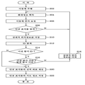
도 2는 본 발명에 따라 이동체를 위한 인공 표식물의 지도를 작성하는 과정을 도시한 순서도이다.Figure 2 is a flow chart illustrating a process of creating a map of the artificial marker for a moving object in accordance with the present invention.
도 2를 참조하면, 인코더(102), 레이저 센서(104) 및 인공 표식물 탐지기(106)가 장착된 이동체(306)가 광역 공간을 주행할 때(단계 202), 인코더(102)와 레이저 센서(104)를 통해 측정되는 환경 정보, 즉 이동체의 움직인 위치 정보와 인공 표식물이 설치된 주변 물들의 위치 정보가 위치 보정 블록(108)으로 전달되고, 위치 보정 블록(108)에서는 측정된 주변 물체들의 위치 정보를 이용하여 이동체의 위치를 보정한 후 이동체의 보정된 위치 정보와 주변 물체들의 위치 정보를 인공 표식물 탐색 블록(110)으로 전달한다(단계 206). 여기에서, 이동체의 위치 정보 보정은, 예컨대 칼만 확장 필터 등을 이용하여 수행될 수 있다.Referring to FIG. 2, when the moving
그리고, 인공 표식물 탐지기(106)에서는 포인터를 이용한 트래킹을 통해 이동체에 인접하는 인공 표식물의 영상(카메라 또는 전파 탐지기를 통해 얻은 영상)을 촬상하여 인공 표식물 탐색 블록(110)으로 전달한다.In addition, the
이에 응답하여 인공 표식물 탐색 블록(110)에서는, 인공 표식물이 탐색된 것으로 판단되면(단계 208), 이동체의 보정된 위치 정보, 인공 표식물이 설치된 주변 물체들의 위치 정보, 인공 표식물의 영상 정보(영상 분석 정보)를 이용하여 인공 표식물의 상대적 위치 정보 값을 산출하여 데이터베이스(116)에 저장한 후(단계 210), 이를 지도 대상 판단 블록(112)으로 통지한다. 여기에서, 상대적 위치 정보 값은, 일 예로서 도 4에 도시된 바와 같이, 인공 표식물 탐지기(106)의 중앙이 원점이 되어 인공 표식물이 설치된 위치까지의 상대적인 좌표인 (ID, Δx, Δy, Δ θ, Δz) 또는 (ID, Δd, Δθ, Δz) 형태로 측정될 수 있다.In response to the artificial
다음에, 지도 대상 판단 블록(112)에서는, 인공 표식물 탐색 블록(110)으로부터의 통지에 응답하여 데이터베이스(116)를 탐색함으로써(단계 212), 탐색된 인공 표식물의 현재 탐지 ID가 이전 탐지 ID인지의 여부를 체크한다(단계 214).Next, in the mapping
상기 단계(214)에서의 체크 결과, 탐색된 인공 표식물의 현재 탐지 ID가 이전 탐지 ID가 아닌 것으로 판단될 때 처리는 후술하는 단계(220)로 진행되어 탐색된 인공 표식물에 대한 지도 작성 프로세스(해당 인공 표식물의 상대적 위치 정보 값을 전역 좌표 값으로 계산하여 지도 정보로서 저장하는 프로세스)가 실행된다.As a result of the check in
상기 단계(214)에서의 체크 결과, 탐색된 인공 표식물의 현재 탐지 ID가 이전 탐지 ID이면, 지도 대상 판단 블록(112)에서는 이동체와 탐색된 인공 표식물 사이의 현재 탐지 거리와 이전 탐지 ID에 해당하는 이전 탐지 거리를 비교한다(단계 216).As a result of the check in
상기 단계(216)에서의 비교 결과, 현재 탐지 거리가 이전 탐지 거리보다 상대적으로 클 때 처리는 단계(218)를 경유하여 전술한 단계(204)로 진행되는데, 단계(218)에서는 해당 인공 표식물에 대해 산출한 상대적 위치 정보 값을 데이터베이스(116)에서 삭제시킨다.As a result of the comparison in
한편, 단계(216)에서의 비교 결과, 현재 탐지 거리가 이전 탐지 거리보다 상대적으로 작을 때, 지도 대상 판단 블록(112)에서는 해당 인공 표식물을 지도 작성 대상 인공 표식물로 분류하여 지도 작성 블록(114)으로 통지한다.On the other hand, as a result of the comparison in
이에 응답하여, 지도 작성 블록(114)에서는 데이터베이스(116)로부터 탐색된 인공 표식물의 상대적 위치 정보 값을 인출하고, 이 인출된 상대적 위치 정보 값을 이용하여 탐색된 인공 표식물의 전역 좌표를 계산한 후(단계 220), 전역 좌표와 해당 인공 표식물의 ID를 지도 정보로서 데이터베이스(116)에 저장(등록)한다(단계 222).In response, the
즉, 본 발명에 따르면 , 상술한 바와 같이 이동체를 주행시키면서 자동으로 수행되는 일련의 프로세스를 통해 광역 공간에 설치된 인공 표식물들에 대한 전역 좌표와 ID를 계산하여 데이터베이스에 등록하는 방식으로 인공 표식물들에 대한 지도 정보를 작성하게 된다.That is, according to the present invention, the global coordinates and IDs for the artificial markers installed in the wide-area space are calculated and registered in the database through a series of processes automatically performed while driving the moving object as described above. Map information will be created.
다음에, 상술한 바와 같은 일련의 과정을 통해 작성한 인공 표식물 지도를 이용하여 이동체의 위치를 측정하는 장치 및 방법에 대하여 설명한다.Next, a description will be given of an apparatus and method for measuring the position of a moving object using an artificial marker map created through a series of processes as described above.
도 6은 본 발명에 따라 인공 표식물 지도를 이용하여 이동체의 위치를 측정하는 이동체 위치 측정 장치의 블록구성도로서, 인코더(602), 레이저 센서(604), 인공 표식물 탐지기(606), 위치 보정 블록(608), 인공 표식물 탐색 블록(610), 이동체 위치 계산 블록(612) 및 지도 정보 DB(614) 등을 포함한다.FIG. 6 is a block diagram of an apparatus for measuring the position of a moving object using an artificial marker map according to the present invention. The
도 6을 참조하면, 도 1의 일부 구성부재들과 대응하는 각 구성부재, 즉 인코더(602), 레이저 센서(604), 인공 표식물 탐지기(606), 위치 보정 블록(608) 및 인공 표식물 탐색 블록(610)의 각 기능들은 도 1에 도시된 대응하는 각 구성부재들의 기능과 실질적으로 동일하다. 따라서, 명세서의 간결화를 위한 불필요한 중복기재를 피하기 위하여 여기에서는 이들 구성부재들에 대한 설명을 생략한다.Referring to FIG. 6, each component corresponding to some of the components of FIG. 1, that is, the
즉, 인공 표식물 탐색 블록(610)은, 광역 공간에서 인공 표식물이 탐색되면, 산출된 해당 인공 표식물의 ID를 포함하는 상대적 위치 정보 값(이동체로부터 인공 표식물까지의 상대 위치 정보 값)을 이동체 위치 계산 블록(612)으로 전달한다.That is, the artificial
이에 응답하여, 이동체 위치 계산 블록(612)은 지도 정보 DB(614)를 탐색함으로써, 탐색된 인공 표식물의 ID가 지도 정보 DB(614)상에 존재하는지를 체크하고, ID가 존재할 때 지도 정보 DB(614)로부터 해당 인공 표식물의 전역 좌표 값(전역 좌표 위치 정보)을 인출하고, 이 인출된 전역 좌표 값과 탐색된 인공 표식물의 상대적 위치 정보 값을 이용하여 이동체의 위치를 계산한다. 이를 위하여, 지도 정보 DB(614)에는 광역 공간상에 설치된 각 인공 표식물들에 대한 전역 좌표 값들이 저장되어 있다.In response, the moving object position calculation block 612 searches the
보다 상세하게, 이동체 위치 계산 블록(612)에서는 아래의 도 8 및 수학식 2를 이용하여 이동체의 위치를 계산한다. 즉, 도 8은 본 발명에 따라 인공 표식물 지도를 이용하여 인공 표식물의 위치를 측정하는 과정을 설명하기 위한 예시도이다.More specifically, the moving object
[수학식 2]&Quot; (2) "
ΘC=ΘT-ΔθΘ C = Θ T -Δθ
XC=XT-Δx·cos(Θc)+Δy·sin(Θc)X C = X T -Δxcos (Θ c ) + Δysin (Θ c )
YC=YT-Δx·sin(Θc)-Δy·cos(Θc)Y C = Y T -Δxsin (Θ c ) -Δycos (Θ c )
다음에, 상술한 바와 같은 구성을 갖는 본 발명의 이동체 위치 측정 장치를 이용하여 광역 공간에 설치된 인공 표식물을 이용하여 이동체의 위치를 측정하는 일련의 과정에 대하여 설명한다.Next, a series of processes for measuring the position of the moving object using the artificial marker installed in the wide area using the moving object position measuring device of the present invention having the above-described configuration will be described.
도 7은 본 발명에 따라 인공 표식물 지도를 이용하여 이동체의 위치를 측정하는 과정을 도시한 순서도이다.7 is a flowchart illustrating a process of measuring the position of a moving object using an artificial marker map according to the present invention.
도 7을 참조하면, 단계 702 내지 710 각각의 처리는 전술한 도 2에 도시된 단계 202 내지 210의 대응하는 각 단계에서와 처리와 실질적으로 동일하다. 따라서, 명세서의 간결화를 위한 불필요한 중복기재를 피하기 위하여 여기에서는 이들 단계들에 대한 설명을 생략한다.Referring to FIG. 7, the processing of each of
즉, 인공 표식물 탐색 블록(610)에서는 광역 공간에서 인공 표식물이 탐색되어 산출한 해당 인공 표식물의 ID를 포함하는 상대적 위치 정보 값(이동체로부터 인공 표식물까지의 상대 위치 정보 값)을 이동체 위치 계산 블록(612)으로 전달한다.That is, in the artificial
다음에, 이동체 위치 계산 블록(612)에서는 지도 정보 DB(614)를 탐색하여 탐색된 인공 표식물의 ID(탐지 ID)가 지도 정보 DB(614)상에 존재하는지를 체크하는데(단계 712, 714), 여기에서의 체크 결과 탐지 ID가 지도 정보 DB(614)에 존재하지 않는 ID인 것으로 판단되면, 처리는 단계(702)로 진행되어 그 이후의 과정을 처리하게 된다.Next, the moving object position calculation block 612 searches the
상기 단계(714)에서의 체크 결과, 탐지 ID가 지도 정보 DB(614)에 존재하는 ID인 것으로 판단되면, 이동체 위치 계산 블록(612)에서는 지도 정보 DB(614)로부터 해당 인공 표식물의 전역 좌표 값(전역 좌표 위치 정보)을 인출한다(단계 716).If it is determined in the
이후, 이동체 위치 계산 블록(612)에서는 인출된 전역 좌표 값과 탐색된 인 공 표식물의 상대적 위치 정보 값을 이용하여 이동체의 위치를 계산한다(단계 718).Subsequently, the moving object
따라서, 본 발명의 이동체 위치 측정 기법에 따르면, 이동체에 탑재시킨 인공 표식물 지도를 이용하여 이동체의 위치를 신속, 고정밀하게 측정할 수 있다.Therefore, according to the moving object position measuring technique of the present invention, the position of the moving object can be measured quickly and accurately by using the artificial marker map mounted on the moving object.
이상의 설명에서는 본 발명의 바람직한 실시 예들을 제시하여 설명하였으나 본 발명이 반드시 이에 한정되는 것은 아니며, 본 발명이 속하는 기술분야에서 통상의 지식을 가진 자라면 본 발명의 기술적 사상을 벗어나지 않는 범위 내에서 여러 가지 치환, 변형 및 변경이 가능함을 것을 쉽게 알 수 있을 것이다.In the foregoing description, the present invention has been described with reference to preferred embodiments, but the present invention is not necessarily limited thereto. Those skilled in the art will appreciate that the present invention may be modified without departing from the spirit of the present invention. It will be readily appreciated that branch substitutions, modifications and variations are possible.
도 1은 본 발명에 따른 이동체를 위한 인공 표식물의 지도 작성 장치의 블록구성도,1 is a block diagram of an apparatus for preparing artificial markers for moving objects according to the present invention;
도 2는 본 발명에 따라 이동체를 위한 인공 표식물의 지도를 작성하는 과정을 도시한 순서도,Figure 2 is a flow chart illustrating a process of creating a map of the artificial marker for the moving body according to the present invention,
도 3은 본 발명에 따라 이동체에 장착된 인공 표식물 탐지기를 통해 인공 표식물의 위치를 탐지하는 과정을 설명하기 위한 예시도,3 is an exemplary view for explaining a process of detecting the position of the artificial marker through the artificial marker detector mounted on the moving body according to the present invention,
도 4는 본 발명에 따라 인공 표식물의 상대적 위치 정보 값을 산출하는 것을 설명하기 위한 예시도,4 is an exemplary diagram for explaining calculating a relative position information value of an artificial marker according to the present invention;
도 5는 본 발명에 따라 상대적 위치 정보 값을 이용하여 인용 표식물의 전역 좌표 값을 계산하는 과정을 설명하기 위한 예시도,5 is an exemplary view for explaining a process of calculating a global coordinate value of a citation marker using relative position information values according to the present invention;
도 6은 본 발명에 따라 인공 표식물 지도를 이용하여 이동체의 위치를 측정하는 이동체 위치 측정 장치의 블록구성도,Figure 6 is a block diagram of a moving object position measuring device for measuring the position of the moving object using an artificial marker map according to the present invention,
도 7은 본 발명에 따라 인공 표식물 지도를 이용하여 이동체의 위치를 측정하는 과정을 도시한 순서도,7 is a flowchart illustrating a process of measuring the position of a moving object using an artificial marker map according to the present invention;
도 8은 본 발명에 따라 인공 표식물 지도를 이용하여 인공 표식물의 위치를 측정하는 과정을 설명하기 위한 예시도.8 is an exemplary view for explaining a process of measuring the position of the artificial marker using the artificial marker map in accordance with the present invention.
<도면의 주요부분에 대한 부호의 설명>Description of the Related Art
102, 602 : 인코더102, 602: Encoder
104, 604 : 레이저 센서104, 604: Laser Sensor
106, 606 : 인공 표식물 탐지기106, 606: Artificial Mark Detector
108, 608 : 위치 보정 블록108,608: position correction block
110, 610 : 인공 표식물 탐색 블록110, 610: artificial marker navigation block
112 : 지도 대상 판단 블록112: judgment target block
114 : 지도 작성 블록114: mapping block
116 : 데이터베이스116: database
612 : 이동체 위치 계산 블록612: moving object position calculation block
614 : 지도 정보 DB614: Map information DB
Claims (20)
Priority Applications (2)
| Application Number | Priority Date | Filing Date | Title |
|---|---|---|---|
| KR1020090128336A KR101314588B1 (en) | 2009-10-26 | 2009-12-21 | Method and apparatus for producing map of artificial mark, method and apparatus for measuring position of mobile object by using same |
| US12/912,199 US20110098923A1 (en) | 2009-10-26 | 2010-10-26 | Method of and apparatus for creating map of artificial marks, and method and apparatus for measuring position of moving object using the map |
Applications Claiming Priority (3)
| Application Number | Priority Date | Filing Date | Title |
|---|---|---|---|
| KR1020090101674 | 2009-10-26 | ||
| KR20090101674 | 2009-10-26 | ||
| KR1020090128336A KR101314588B1 (en) | 2009-10-26 | 2009-12-21 | Method and apparatus for producing map of artificial mark, method and apparatus for measuring position of mobile object by using same |
Publications (2)
| Publication Number | Publication Date |
|---|---|
| KR20110046212A KR20110046212A (en) | 2011-05-04 |
| KR101314588B1 true KR101314588B1 (en) | 2013-10-07 |
Family
ID=43899125
Family Applications (1)
| Application Number | Title | Priority Date | Filing Date |
|---|---|---|---|
| KR1020090128336A Active KR101314588B1 (en) | 2009-10-26 | 2009-12-21 | Method and apparatus for producing map of artificial mark, method and apparatus for measuring position of mobile object by using same |
Country Status (2)
| Country | Link |
|---|---|
| US (1) | US20110098923A1 (en) |
| KR (1) | KR101314588B1 (en) |
Families Citing this family (23)
| Publication number | Priority date | Publication date | Assignee | Title |
|---|---|---|---|---|
| US11835343B1 (en) | 2004-08-06 | 2023-12-05 | AI Incorporated | Method for constructing a map while performing work |
| US10809071B2 (en) | 2017-10-17 | 2020-10-20 | AI Incorporated | Method for constructing a map while performing work |
| US20160349057A1 (en) * | 2010-10-13 | 2016-12-01 | Elbit Systems Ltd. | Multiple data sources pedestrian navigation system |
| KR101272422B1 (en) * | 2012-02-29 | 2013-06-07 | 부산대학교 산학협력단 | Device and method for locationing using laser scanner and landmark matching |
| CN103379620A (en) * | 2012-04-19 | 2013-10-30 | 国民技术股份有限公司 | Positioning method and positioning system |
| CN102829775A (en) * | 2012-08-29 | 2012-12-19 | 成都理想境界科技有限公司 | Indoor navigation method, systems and equipment |
| DE202013003415U1 (en) * | 2013-04-11 | 2013-05-28 | Abb Technology Ag | Arrangement for the physical localization of field devices in process plants |
| CN103398717B (en) * | 2013-08-22 | 2016-04-20 | 成都理想境界科技有限公司 | The location of panoramic map database acquisition system and view-based access control model, air navigation aid |
| US20150126213A1 (en) * | 2013-11-01 | 2015-05-07 | Gfi Software Ip S.A.R.L. | System for Mapping an Indoor Space Using Wireless Network and Method |
| KR101470761B1 (en) * | 2013-11-21 | 2014-12-08 | 충북대학교 산학협력단 | Parking Control Apparatus and Method for Omni-directional Telepresence Mobile Robot |
| KR102158029B1 (en) | 2014-01-03 | 2020-09-21 | 한국전자통신연구원 | Method and apparatus for recognizing indoor location using field intensity map |
| JP2015138010A (en) * | 2014-01-24 | 2015-07-30 | 清水建設株式会社 | Position detection system and method for photographing camera |
| KR101575597B1 (en) * | 2014-07-30 | 2015-12-08 | 엘지전자 주식회사 | Robot cleaning system and method of controlling robot cleaner |
| CN104390645B (en) * | 2014-12-09 | 2017-11-07 | 重庆邮电大学 | A kind of intelligent wheel chair indoor navigation method of view-based access control model information |
| BR112017015589A8 (en) | 2015-01-20 | 2022-11-29 | Beijing Didi Infinity Technology & Dev Co Ltd | SYSTEMS AND METHODS FOR PROVIDING INFORMATION TO AN ON-DEMAND SERVICE |
| CN104581637A (en) * | 2015-01-20 | 2015-04-29 | 北京嘀嘀无限科技发展有限公司 | Positioning method and equipment |
| CN107730965A (en) * | 2016-12-14 | 2018-02-23 | 西安艾润物联网技术服务有限责任公司 | Vehicles management method and vehicle management system based on Intelligent unattended machine |
| US11274929B1 (en) * | 2017-10-17 | 2022-03-15 | AI Incorporated | Method for constructing a map while performing work |
| US11393114B1 (en) | 2017-11-08 | 2022-07-19 | AI Incorporated | Method and system for collaborative construction of a map |
| CN108318050B (en) * | 2017-12-14 | 2019-08-23 | 富华科精密工业(深圳)有限公司 | Central controller and the system and method for utilizing the central controller mobile navigation |
| FI20196023A1 (en) | 2019-11-27 | 2021-05-28 | Novatron Oy | Method for determining location and orientation of machine |
| KR102196076B1 (en) * | 2020-05-15 | 2020-12-29 | 주식회사 케이스랩 | Method and Apparatus for Generating Trigonal-Hexagonal Map And for Determining Global Position of Mobile Object Using The Same |
| US12536865B2 (en) * | 2022-09-30 | 2026-01-27 | Aristocrat Technologies, Inc. | Systems and methods for mobile kiosk remote administration in electronic gaming |
Citations (4)
| Publication number | Priority date | Publication date | Assignee | Title |
|---|---|---|---|---|
| KR20040029493A (en) * | 2002-10-01 | 2004-04-08 | 삼성전자주식회사 | Landmark, apparatus and method for determining position of autonomous vehicles effectively |
| KR20050115647A (en) * | 2004-06-04 | 2005-12-08 | 주식회사 코맥스 | Self localization system of autonomous vehicles using landmark and method thereof |
| KR20070081798A (en) * | 2007-07-27 | 2007-08-17 | 삼성전자주식회사 | An apparatus and method for estimating and generating a location of a moving object using an upward image and a computer-readable recording medium storing a computer program controlling the apparatus |
| KR20090047639A (en) * | 2007-11-08 | 2009-05-13 | 한국전자통신연구원 | Apparatus and method for obtaining position of artificial marker |
Family Cites Families (9)
| Publication number | Priority date | Publication date | Assignee | Title |
|---|---|---|---|---|
| US7437226B2 (en) * | 2003-08-20 | 2008-10-14 | Samsung Electronics Co., Ltd. | Method of constructing artificial mark for autonomous driving, apparatus and method of determining position of intelligent system using artificial mark and intelligent system employing the same |
| US7689321B2 (en) * | 2004-02-13 | 2010-03-30 | Evolution Robotics, Inc. | Robust sensor fusion for mapping and localization in a simultaneous localization and mapping (SLAM) system |
| KR100776215B1 (en) * | 2005-01-25 | 2007-11-16 | 삼성전자주식회사 | An apparatus and method for estimating and mapping a moving object using an upstream image and a computer-readable recording medium storing a computer program controlling the apparatus |
| US8050863B2 (en) * | 2006-03-16 | 2011-11-01 | Gray & Company, Inc. | Navigation and control system for autonomous vehicles |
| US20070271011A1 (en) * | 2006-05-12 | 2007-11-22 | Samsung Electronics Co., Ltd. | Indoor map building apparatus, method, and medium for mobile robot |
| US20100026555A1 (en) * | 2006-06-09 | 2010-02-04 | Whittaker William L | Obstacle detection arrangements in and for autonomous vehicles |
| US7783427B1 (en) * | 2006-07-14 | 2010-08-24 | Rockwell Collins, Inc. | Combined runway obstacle detection system and method |
| KR100877072B1 (en) * | 2007-06-28 | 2009-01-07 | 삼성전자주식회사 | Method and apparatus for simultaneously creating and cleaning maps for mobile robots |
| US8340852B2 (en) * | 2009-04-29 | 2012-12-25 | Honeywell International Inc. | System and method for simultaneous localization and map building |
-
2009
- 2009-12-21 KR KR1020090128336A patent/KR101314588B1/en active Active
-
2010
- 2010-10-26 US US12/912,199 patent/US20110098923A1/en not_active Abandoned
Patent Citations (4)
| Publication number | Priority date | Publication date | Assignee | Title |
|---|---|---|---|---|
| KR20040029493A (en) * | 2002-10-01 | 2004-04-08 | 삼성전자주식회사 | Landmark, apparatus and method for determining position of autonomous vehicles effectively |
| KR20050115647A (en) * | 2004-06-04 | 2005-12-08 | 주식회사 코맥스 | Self localization system of autonomous vehicles using landmark and method thereof |
| KR20070081798A (en) * | 2007-07-27 | 2007-08-17 | 삼성전자주식회사 | An apparatus and method for estimating and generating a location of a moving object using an upward image and a computer-readable recording medium storing a computer program controlling the apparatus |
| KR20090047639A (en) * | 2007-11-08 | 2009-05-13 | 한국전자통신연구원 | Apparatus and method for obtaining position of artificial marker |
Also Published As
| Publication number | Publication date |
|---|---|
| KR20110046212A (en) | 2011-05-04 |
| US20110098923A1 (en) | 2011-04-28 |
Similar Documents
| Publication | Publication Date | Title |
|---|---|---|
| KR101314588B1 (en) | Method and apparatus for producing map of artificial mark, method and apparatus for measuring position of mobile object by using same | |
| Wang et al. | Keyframe based large-scale indoor localisation using geomagnetic field and motion pattern | |
| Liu et al. | Vision-aware air-ground cooperative target localization for UAV and UGV | |
| CN103472823B (en) | A kind of grating map creating method of intelligent robot | |
| JP5296746B2 (en) | Map creation method and apparatus and localization method using the map | |
| CN114413909A (en) | Indoor mobile robot positioning method and system | |
| CN103674015B (en) | Trackless positioning navigation method and device | |
| CN110174136A (en) | A kind of underground piping intelligent measurement robot and intelligent detecting method | |
| JP6826421B2 (en) | Equipment patrol system and equipment patrol method | |
| CN107132846B (en) | Gamma radiation detection method in unfamiliar indoor scene | |
| US8781732B2 (en) | Apparatus and method for recognizing position of moving object | |
| Kachurka et al. | WeCo-SLAM: Wearable cooperative SLAM system for real-time indoor localization under challenging conditions | |
| Lee et al. | Magnetic indoor positioning system using deep neural network | |
| CN106840148A (en) | Wearable positioning and path guide method based on binocular camera under outdoor work environment | |
| JP5892785B2 (en) | Information processing apparatus and information processing method | |
| CN109782756A (en) | With independently around the Intelligent Mobile Robot of barrier walking function | |
| CN104501801B (en) | A kind of indoor orientation method | |
| CN111982099A (en) | Robot hybrid positioning method, apparatus, device and computer readable medium | |
| Khoury et al. | Infrastructureless approach for ubiquitous user location tracking in construction environments | |
| Tao et al. | Automated processing of mobile mapping image sequences | |
| US20230175860A1 (en) | Multi-agent map generation | |
| Liu et al. | A review of positioning technologies for personnel and equipment in underground mines | |
| Jametoni et al. | A study on autonomous drone positioning method | |
| JP2019168226A (en) | Plant facility navigation system and plant facility navigation method | |
| US11644527B2 (en) | Lost-in-forest GPS-denied positioning system |
Legal Events
| Date | Code | Title | Description |
|---|---|---|---|
| A201 | Request for examination | ||
| PA0109 | Patent application |
Patent event code: PA01091R01D Comment text: Patent Application Patent event date: 20091221 |
|
| PA0201 | Request for examination | ||
| PG1501 | Laying open of application | ||
| N231 | Notification of change of applicant | ||
| PN2301 | Change of applicant |
Patent event date: 20111128 Comment text: Notification of Change of Applicant Patent event code: PN23011R01D |
|
| E902 | Notification of reason for refusal | ||
| PE0902 | Notice of grounds for rejection |
Comment text: Notification of reason for refusal Patent event date: 20130121 Patent event code: PE09021S01D |
|
| E701 | Decision to grant or registration of patent right | ||
| PE0701 | Decision of registration |
Patent event code: PE07011S01D Comment text: Decision to Grant Registration Patent event date: 20130711 |
|
| GRNT | Written decision to grant | ||
| PR0701 | Registration of establishment |
Comment text: Registration of Establishment Patent event date: 20130927 Patent event code: PR07011E01D |
|
| PR1002 | Payment of registration fee |
Payment date: 20130930 End annual number: 3 Start annual number: 1 |
|
| PG1601 | Publication of registration | ||
| FPAY | Annual fee payment |
Payment date: 20161031 Year of fee payment: 4 |
|
| PR1001 | Payment of annual fee |
Payment date: 20161031 Start annual number: 4 End annual number: 4 |
|
| FPAY | Annual fee payment |
Payment date: 20170823 Year of fee payment: 5 |
|
| PR1001 | Payment of annual fee |
Payment date: 20170823 Start annual number: 5 End annual number: 5 |
|
| FPAY | Annual fee payment |
Payment date: 20180829 Year of fee payment: 6 |
|
| PR1001 | Payment of annual fee |
Payment date: 20180829 Start annual number: 6 End annual number: 6 |
|
| FPAY | Annual fee payment |
Payment date: 20190826 Year of fee payment: 7 |
|
| PR1001 | Payment of annual fee |
Payment date: 20190826 Start annual number: 7 End annual number: 7 |
|
| PR1001 | Payment of annual fee |
Payment date: 20200831 Start annual number: 8 End annual number: 8 |
|
| PR1001 | Payment of annual fee |
Payment date: 20210820 Start annual number: 9 End annual number: 9 |