KR101305774B1 - Headlamp structure for vehicle - Google Patents
Headlamp structure for vehicle Download PDFInfo
- Publication number
- KR101305774B1 KR101305774B1 KR1020110085918A KR20110085918A KR101305774B1 KR 101305774 B1 KR101305774 B1 KR 101305774B1 KR 1020110085918 A KR1020110085918 A KR 1020110085918A KR 20110085918 A KR20110085918 A KR 20110085918A KR 101305774 B1 KR101305774 B1 KR 101305774B1
- Authority
- KR
- South Korea
- Prior art keywords
- lamp
- case
- battery
- storage case
- storage
- Prior art date
- Legal status (The legal status is an assumption and is not a legal conclusion. Google has not performed a legal analysis and makes no representation as to the accuracy of the status listed.)
- Expired - Fee Related
Links
Images


Classifications
-
- B—PERFORMING OPERATIONS; TRANSPORTING
- B60—VEHICLES IN GENERAL
- B60Q—ARRANGEMENT OF SIGNALLING OR LIGHTING DEVICES, THE MOUNTING OR SUPPORTING THEREOF OR CIRCUITS THEREFOR, FOR VEHICLES IN GENERAL
- B60Q3/00—Arrangement of lighting devices for vehicle interiors; Lighting devices specially adapted for vehicle interiors
- B60Q3/50—Mounting arrangements
- B60Q3/51—Mounting arrangements for mounting lighting devices onto vehicle interior, e.g. onto ceiling or floor
-
- B—PERFORMING OPERATIONS; TRANSPORTING
- B60—VEHICLES IN GENERAL
- B60Q—ARRANGEMENT OF SIGNALLING OR LIGHTING DEVICES, THE MOUNTING OR SUPPORTING THEREOF OR CIRCUITS THEREFOR, FOR VEHICLES IN GENERAL
- B60Q3/00—Arrangement of lighting devices for vehicle interiors; Lighting devices specially adapted for vehicle interiors
- B60Q3/80—Circuits; Control arrangements
- B60Q3/82—Switches specially adapted for vehicle interior lighting, e.g. switching by tilting the lens
-
- B—PERFORMING OPERATIONS; TRANSPORTING
- B60—VEHICLES IN GENERAL
- B60R—VEHICLES, VEHICLE FITTINGS, OR VEHICLE PARTS, NOT OTHERWISE PROVIDED FOR
- B60R16/00—Electric or fluid circuits specially adapted for vehicles and not otherwise provided for; Arrangement of elements of electric or fluid circuits specially adapted for vehicles and not otherwise provided for
- B60R16/02—Electric or fluid circuits specially adapted for vehicles and not otherwise provided for; Arrangement of elements of electric or fluid circuits specially adapted for vehicles and not otherwise provided for electric constitutive elements
- B60R16/04—Arrangement of batteries
Landscapes
- Engineering & Computer Science (AREA)
- Mechanical Engineering (AREA)
- Arrangements Of Lighting Devices For Vehicle Interiors, Mounting And Supporting Thereof, Circuits Therefore (AREA)
Abstract
본 발명은 자동차용 램프 구조에 관한 것으로, 자동차 내부 벽면 또는 천정에 장착하고, 배터리와 연결된 접촉단자를 구비한 수납 케이스; 및 상기 수납 케이스에 탈부착 가능하게 장착하는 램프장치를 포함하며, 상기 램프장치는 수납 케이스에 형성한 수납홈에 탈부착 가능하게 장착하는 램프 케이스, 상기 램프 케이스의 측면에 구비한 제1 램프, 상기 램프 케이스의 일측 단부에 구비한 제2 램프, 및 상기 접촉단자와 접촉되는 연결단자를 구비하여 배터리로부터 공급된 전원을 충전하는 충전지를 마련한 제어부, 상기 배터리로부터 제1 램프 또는 제2 램프로 전원을 공급하거나 공급을 차단하는 스위치 포함한다.The present invention relates to a lamp structure for an automobile, comprising: a storage case mounted on a vehicle interior wall or ceiling and having a contact terminal connected to a battery; And a lamp device detachably attached to the storage case, wherein the lamp device includes a lamp case detachably attached to a storage groove formed in the storage case, a first lamp provided on a side of the lamp case, and the lamp. A control unit including a second lamp provided at one end of the case and a connection terminal in contact with the contact terminal to provide a rechargeable battery for charging power supplied from the battery, and supplying power from the battery to the first lamp or the second lamp; Includes a switch to turn off or cut off the supply.
Description
본 발명은 자동차용 램프 구조에 관한 것으로서, 보다 상세하게는 실내 조명 램프와 휴대용 조명램프를 겸용으로 사용할 수 있는 자동차용 램프 구조에 관한 것이다.
BACKGROUND OF THE INVENTION 1. Field of the Invention The present invention relates to a lamp structure for automobiles, and more particularly, to a lamp structure for automobiles that can be used as both a room lighting lamp and a portable lighting lamp.
일반적으로 자동차에는 실내 공간을 조명하기 위한 다수의 조명 램프가 구비되어 있으며, 이러한 조명 램프는 카고 램프 및 글로버 박스 램프, 러기지 램프 등이 있다.In general, a vehicle is provided with a plurality of lighting lamps for illuminating the interior space, such lighting lamps include cargo lamps and glover box lamps, luggage lamps.
즉, 상기한 조명 램프는 자동차 실내 내벽 또는 천정에 고정되어 있어 사용자의 스위치 조작에 따라 빛을 발산한다.
한편, 종래기술에 따른 조명 램프로 특허공개공보 10-1997-0037764의 "조명 각도 조절형 자동차의 실내등"이 개시된 바 있다.That is, the lighting lamp is fixed to the interior wall or ceiling of the vehicle to emit light in accordance with the user's switch operation.
On the other hand, as a lighting lamp according to the prior art has been disclosed in the "indoor lighting of the lighting angle adjustable vehicle" of Patent Publication No. 10-1997-0037764.
그러나 상기한 종래의 조명 램프는 비상사태 발생시 자동차의 실내는 조명할 수 있지만, 자동차 밖은 조명할 수 없어, 별도의 휴대용 조명 램프를 구비해야 하는 문제점이 있었다.
However, the above-described conventional lighting lamps can illuminate the interior of a vehicle during an emergency, but cannot illuminate outside the vehicle, and thus have a problem of providing a separate portable lighting lamp.
전술한 문제점을 해결하기 위한 본 발명이 이루고자 하는 기술적 과제는, 실내 조명 램프와 휴대용 조명램프를 겸용으로 사용할 수 있는 자동차용 램프 구조를 제공하기 위한 것이다.
The technical problem to be solved by the present invention for solving the above problems is to provide a lamp structure for automobiles that can be used in combination with a room lighting lamp and a portable lighting lamp.
전술한 기술적 과제를 달성하기 위한 수단으로서, 자동차용 램프 구조는 자동차 내부 벽면 또는 천정에 장착하고, 배터리와 연결된 접촉단자를 구비한 수납 케이스; 및 상기 수납 케이스에 탈부착 가능하게 장착하는 램프장치를 포함하며, 상기 램프장치는 수납 케이스에 형성한 수납홈에 탈부착 가능하게 장착하는 램프 케이스, 상기 램프 케이스의 측면에 구비한 제1 램프, 상기 램프 케이스의 일측 단부에 구비한 제2 램프, 및 상기 접촉단자와 접촉되는 연결단자를 구비하여 배터리로부터 공급된 전원을 충전하는 충전지를 마련한 제어부, 상기 배터리로부터 제1 램프 또는 제2 램프로 전원을 공급하거나 공급을 차단하는 스위치 포함하는 것을 특징으로 한다.
As a means for achieving the above technical problem, a vehicle lamp structure is mounted on the vehicle interior wall or ceiling, the storage case having a contact terminal connected to the battery; And a lamp device detachably attached to the storage case, wherein the lamp device includes a lamp case detachably attached to a storage groove formed in the storage case, a first lamp provided on a side of the lamp case, and the lamp. A control unit including a second lamp provided at one end of the case and a connection terminal in contact with the contact terminal to provide a rechargeable battery for charging power supplied from the battery, and supplying power from the battery to the first lamp or the second lamp; Or switch to cut off the supply.
본 발명에 따르면, 자동차 실내에 탈부착이 가능하게 조명 램프를 구비함으로써 실내 조명 램프와 휴대용 조명램프를 겸용으로 사용할 수 있어 효율성과 상품성을 증대시킬 수 있고, 더불어 자동차 전원으로 항상 충전이 가능하여 편의성을 증대시킬 수 있는 효과가 있다.
According to the present invention, by providing a lighting lamp to be detachable in the interior of the car can be used both indoor lighting lamps and portable lighting lamps to increase the efficiency and merchandise, and also can always be charged by the car power supply convenience There is an effect that can be increased.
도 1은 본 발명에 따른 자동차용 내장 램프 구조의 결합 상태 사시도.
도 2는 본 발명에 따른 자동차용 내장 램프 구조의 분리 상태 사시도.
도 3은 본 발명에 따른 자동차용 내장 램프 구조의 단면도.
도 4는 본 발명에 따른 조명 램프의 저면사시도.1 is a perspective view of a combined state of the built-in lamp structure for automobiles according to the present invention.
Figure 2 is a perspective view of the separated state of the interior lamp structure for automobiles according to the present invention.
3 is a cross-sectional view of the interior lamp structure for automobiles according to the present invention.
4 is a bottom perspective view of an illumination lamp according to the invention.
이와 같은 목적과 효과를 가지는 본 발명인 자동차용 램프 구조는 자동차 내부 벽면 또는 천정에 장착하고, 배터리와 연결된 접촉단자를 구비한 수납 케이스; 및 상기 수납 케이스에 탈부착 가능하게 장착하는 램프장치를 포함하며, 상기 램프장치는 수납 케이스에 형성한 수납홈에 탈부착 가능하게 장착하는 램프 케이스, 상기 램프 케이스의 측면에 구비한 제1 램프, 상기 램프 케이스의 일측 단부에 구비한 제2 램프, 및 상기 접촉단자와 접촉되는 연결단자를 구비하여 배터리로부터 공급된 전원을 충전하는 충전지를 마련한 제어부, 상기 배터리로부터 제1 램프 또는 제2 램프로 전원을 공급하거나 공급을 차단하는 스위치 포함한다.The lamp structure for a vehicle of the present invention having the above object and effect is mounted on the vehicle interior wall or ceiling, the storage case having a contact terminal connected to the battery; And a lamp device detachably attached to the storage case, wherein the lamp device includes a lamp case detachably attached to a storage groove formed in the storage case, a first lamp provided on a side of the lamp case, and the lamp. A control unit including a second lamp provided at one end of the case and a connection terminal in contact with the contact terminal to provide a rechargeable battery for charging power supplied from the battery, and supplying power from the battery to the first lamp or the second lamp; Includes a switch to turn off or cut off the supply.
상기 램프 케이스는 일측 단부에 형성한 고정돌기를 수납홈 일측에 형성한 고정홈에 삽입하고, 타측에 형성한 잠금돌기를 수납홈 타측에 구비한 래치장치에 결합한다.The lamp case inserts the fixing protrusion formed at one end into the fixing groove formed at one side of the receiving groove, and couples the locking protrusion formed at the other side to the latch device provided at the other side of the receiving groove.
상기 수납 케이스는 수납홈 타측에 손가락이 들어 갈 수 있게 손가락 삽입홈을 형성한다.The storage case forms a finger insertion groove to allow a finger to enter the other side of the storage groove.
상기 수납 케이스는 수납홈 바닥면에 노이즈 방지용 댐퍼를 구비한다.The storage case includes a damper for preventing noise on the bottom surface of the storage groove.
상기 수납케이스의 측부에는 전자기기를 충전하기 위한 파워아웃렛부를 구비하며, 상기 파워아웃렛부는 제어부의 충전지와 연결한다.The side of the storage case is provided with a power outlet for charging the electronic device, the power outlet is connected to the rechargeable battery of the control unit.
이하, 첨부한 도면을 참조하여 본 발명이 속하는 기술분야에서 통상의 지식을 가진 자가 용이하게 실시할 수 있도록 본 발명의 실시예를 상세히 설명한다. 그러나 본 발명은 여러 가지 상이한 형태로 구현될 수 있으며 여기에서 설명하는 실시예에 한정되지 않는다. 그리고 도면에서 본 발명을 명확하게 설명하기 위해서 설명과 관계없는 부분은 생략하였으며, 명세서 전체를 통하여 유사한 부분에 대해서는 유사한 도면 부호를 붙였다.Hereinafter, embodiments of the present invention will be described in detail with reference to the accompanying drawings so that those skilled in the art can easily carry out the present invention. The present invention may, however, be embodied in many different forms and should not be construed as limited to the embodiments set forth herein. In the drawings, parts irrelevant to the description are omitted in order to clearly describe the present invention, and like reference numerals designate like parts throughout the specification.
본 발명에 따른 자동차용 램프 구조는 차 실내에 고정한 수납케이스(100)에 램프장치(200)를 탈부착 가능하게 장착함으로써 실내 조명 램프와 휴대용 조명램프를 겸용으로 사용할 수 있어 효율성과 상품성을 증대시킨 구성이다.Automobile lamp structure according to the present invention can be used to combine the indoor lighting lamp and the portable lighting lamp by detachably mounting the
이와 같은 본 발명에 따른 자동차용 램프 구조는 도 1 내지 도 3에 도시한 바와 같이, 자동차 실내 내벽 또는 천정에 고정하는 수납 케이스(100), 상기 수납 케이스(100)에 탈부착 가능하게 삽입 고정하는 램프장치(200)를 포함한다.As shown in FIGS. 1 to 3, the lamp structure for a vehicle according to the present invention includes a
이하, 본 발명의 자동차용 내장 램프 구조를 보다 상세히 설명한다.Hereinafter, the automotive interior lamp structure of the present invention will be described in more detail.
본 발명인 수납 케이스(100)는 후술하는 램프장치(200)를 수납하는 위한 구성으로, 후면은 자동차 내부 벽면 또는 천정에 삽입 고정하고, 전면에는 수납홈(110)을 형성하며, 상기 수납홈(110)은 램프장치(200)와 동일한 형태로 이루어진다.The
그리고 상기 수납홈(110)의 일측 단부에는 고정홈(120)을 형성하며, 상기 고정홈(120)은 후술하는 램프장치(200)의 일측 단부를 삽입 고정한다.A
또한, 상기 수납홈(110)의 타측 단부에는 램프장치(200)의 타측 단부가 안정적으로 삽입되게 하거나 또는 손가락을 삽입하기 위한 손가락 삽입홈(130)을 형성하며, 상기 삽입홈(130)은 손가락을 삽입할 수 있게 램프 케이스(100) 전면까지 관통되게 형성한다.In addition, the other end of the receiving
또한, 수납홈(110)의 바닥면 타측에는 눌려짐에 따라 걸림 및 걸림해제를 반복 수행하는 공지 기술인 래치장치(140)를 구비하며, 상기 래치장치(140)는 후술하는 램프장치(200)의 타측 단부가 잠금한다.In addition, the other side of the bottom surface of the receiving
또한, 상기 수납홈(110)의 바닥면에는 신축성을 가지는 댐퍼(150)를 구비하며, 상기 댐퍼(150)는 수납홈(110)의 장착하는 램프장치(200)를 지지하여 소음 발생을 방지한다.In addition, the bottom surface of the
이와 같은 구성을 가지는 수납 케이스(100)는 수납홈(110)에 램프장치(200)를 수납하되, 일측 단부에 형성한 고정홈(120)에 램프장치(200)의 일측 단부를 삽입 고정한 상태로 램프장치(200)의 타측 단부를 래치장치(140)에 잠금하여 램프장치(200)를 장착하고, 이후 램프장치(200)의 타측 단부를 누르면, 램프장치(200)의 잠금이 해제되면서 램프장치(200)를 인출할 수 있다.The
한편, 수납홈(110)의 바닥면 일측에는 배터리(미도시)로부터 전원을 공급받을 수 있도록 접촉단자(160)를 구비하며, 상기 접촉단자(160)를 통해 램프장치(200)에 전원을 공급한다.On the other hand, one side of the bottom surface of the receiving
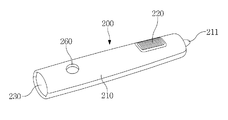
본 발명인 램프장치(200)는 실내 조명 램프와 휴대용 조명 램프를 가지는 구성으로, 램프 케이스(210), 상기 램프 케이스(210)의 측면에 구비한 제1 램프(220), 상기 램프 케이스(210) 단부에 구비한 제2 램프(230), 상기 제1 램프(220)와 제2 램프(230)에 전원을 공급하는 제어부(240), 및 상기 제어부(240)로부터 제1 및 제2 램프(220)(230)로 공급하는 전원을 연결하거나 또는 차단하는 스위치(250)를 포함한다.The
상기 램프 케이스(210)는 일측 단부에 상기 고정홈(120)을 삽입 고정하기 위한 고정돌기(211)를 형성하며, 타측에 상기 래치장치(240)에 삽입 잠금되는 잠금돌기(212)를 형성한다.The
상기 제1 램프(220)는 자동차 실내 조명으로 사용하는 구성으로, 램프 케이스(210)의 측면에 구비한다. 여기서 상기 제1 램프(220)는 후술하는 스위치(250)의 '온' 및 '오프'에 따라 빛을 발산할 수도 있고, 또는 자동차의 ECU 제어에 의해 주위 환경에 따라 빛을 발산할 수도 있다.The
상기 제2 램프(230)는 램프 케이스(210)의 단부에 구비하고, 전원 인가시 외측으로 빛을 발산한다.The
상기 제어부(240)는 배터리로부터 공급받은 전원을 이용하여 제1 램프(220) 또는 제2 램프(230)가 빛을 발산하도록 전원을 인가하는 구성으로, 접촉단자(160)와 연결되도록 연결단자(241)를 형성하고, 배터리로부터 공급받은 전원을 저장하기 위한 충전지(242)를 형성하며, 상기 충전지(242)에 저장된 전원은 제1 및 제2 램프(220)(230)에 선택적으로 공급된다.The
즉, 제어부(240)는 램프 케이스(210)를 수납 케이스(100)에 장착하면, 연결단자(241)와 접촉단자(160)가 연결되면서 배터리의 전원이 충전지(242)로 공급되며, 이에 충전지(242)는 항상 풀로 충전된 상태를 유지하고 , 이에 램프장치(200)를 휴대할 경우 충전지(242)의 충전량 만큼 제2 램프(230)를 사용할 수 있다.That is, when the
상기 스위치(250)는 충전지(242)로부터 제1 램프(220) 또는 제2 램프(230)로 공급되는 전원을 차단하거나 또는 연결하기 위한 구성으로, 충전지(242)와 제1 램프(220) 및 제2 램프(230)의 연결선 사이에 구비하고 램프 케이스(210) 밖으로 인출되게 형성하여 작업자가 조작할 수 있게 한다.The
상기 파워 아웃렛부(260)는 외부 전자기기에 전원을 공급하기 위한 구성으로, 상기 램프 케이스(210)의 외측에 장착하고, 상기 충전지(242)와 연결되면서 충전지(242)로부터 전원을 공급 받는다.The
한편, 상기 파워 아웃렛부(260)는 통상 멀티탭이라고도 하며, 전자기기에 전원을 공급하기 위해 자동차에서 널리 사용한다.On the other hand, the
이하, 본 발명인 자동차용 내장 램프 구조의 사용상태를 설명한다.Hereinafter, the use state of the interior lamp structure for automobiles of the present invention will be described.
[장착상태][Mounted state]
먼저, 램프장치(200)를 수납 케이스(100)에 삽입한다. 이때, 램프장치(200)의 일측에 형성된 고정돌기(211)를 수납 케이스(100)의 고정홈(120)에 삽입 고정한 다음, 램프장치(200)의 잠금돌기(212)를 래치장치(140)에 삽입하여 잠금시키며, 이에 따라 수납 케이스(10O)에 램프장치(200)를 장착할 수 있다.First, the
여기서 댐퍼(150)는 수납 케이스(100)에 장착하는 램프장치(200)를 완충하여 마찰 소음 발생을 방지하고, 이에 안정된 장착을 유도한다.Here, the
한편, 수납 케이스(100)에 램프장치(200)의 장착으로 접촉단자(160)와 제어부(240)의 연결단자(241)가 연결되면서 배터리의 전원이 충전지(242)에 공급되면서 풀 충전 상태까지 전원을 저장한다.Meanwhile, the
[실내용 제1 램프 점등][1st indoor lamp lights]
이와 같은 상태에서, 자동차의 트렁크를 개방하거나 또는 자동차의 도어를 개방하면, 자동차의 ECU는 램프장치(200)의 제어부(240)를 통해 제1 램프(220)에 전원을 공급하도록 제어하며, 이에 제어부(240)는 충전지(242)의 전원을 제1 램프(220)에 공급하면서 제1 램프(220)는 발광하여 자동차 실내에 빛을 발산하고, 이 빛에 의해 운전자 또는 탑승자는 차 실내 작업을 보다 용이하게 진행할 수 있다.In this state, when opening the trunk of the vehicle or opening the door of the vehicle, the ECU of the vehicle controls to supply power to the
[휴대용 제2 램프 점등][Portable second lamp lights up]
한편, 비상사태 발생시 운전자 또는 탑승자는 램프장치(200)를 누르면, 램프장치(200)의 잠금돌기(212)가 래치장치(140)로부터 인출되면서 잠금이 해제되며, 이에 램프장치(200)를 수납 케이스(100)로부터 분리하여 휴대할 수 있고, 휴대한 상태로 스위치(250)를 '온' 시키면 축전지(242)의 전원이 제2 램프(230)로 공급되고, 이에 제2 램프(230)가 발광하면서 빛을 발산하여 어두운 곳의 작업을 용이하게 할 수 있다.On the other hand, when an emergency occurs, the driver or occupant presses the
[파워 아웃렛 사용][Use Power Outlet]
한편, 수납 케이스(100)에 램프장치(200)를 장착한 상태로 전자기기에 연결한 커넥터를 파워 아웃렛부(260)에 결합하면, 축전지(242)의 전원이 파워 아웃렛부(260)에 결합된 커넥터를 통해 전자기기로 전달되면서 전자기기를 사용할 수 있다.On the other hand, when the connector connected to the electronic device with the
본 발명의 범위는 상기 상세한 설명보다는 후술하는 특허청구범위에 의하여 나타내어지며, 특허청구범위의 의미 및 범위 그리고 그 균등 개념으로부터 도출되는 모든 변경 또는 변형된 형태가 본 발명의 범위에 포함되는 것으로 해석되어야 한다.The scope of the present invention is shown by the following claims rather than the above description, and all changes or modifications derived from the meaning and scope of the claims and their equivalents should be construed as being included in the scope of the present invention. do.
100: 수납 케이스 110: 수납홈
120: 고정홈 130: 삽입홈
140: 래치장치 150: 댐퍼
160: 접촉단자 200: 램프장치
210: 램프 케이스 220: 제1 램프
230: 제2 램프 240: 제어부
250: 스위치 260: 파워 아웃렛부100: storage case 110: storage groove
120: fixing groove 130: insertion groove
140: latch device 150: damper
160: contact terminal 200: lamp device
210: lamp case 220: first lamp
230: second lamp 240: control unit
250: switch 260: power outlet portion
Claims (5)
상기 수납 케이스에 탈부착 가능하게 장착하는 램프장치를 포함하며,
상기 램프장치는 수납 케이스에 형성한 수납홈에 탈부착 가능하게 장착하는 램프 케이스, 상기 램프 케이스의 측면에 구비한 제1 램프, 상기 램프 케이스의 일측 단부에 구비한 제2 램프, 및 상기 접촉단자와 접촉되는 연결단자를 구비하여 배터리로부터 공급된 전원을 충전하는 충전지를 마련한 제어부, 상기 배터리로부터 제1 램프 또는 제2 램프로 전원을 공급하거나 공급을 차단하는 스위치를 포함하고,
상기 수납케이스의 측부에는 전자기기를 충전하기 위한 파워아웃렛부를 구비하며,
상기 파워아웃렛부는 제어부의 충전지와 연결되는 자동차용 램프 구조. A storage case mounted on a vehicle interior wall or ceiling and having a contact terminal connected to a battery; And
It includes a lamp device detachably mounted to the storage case,
The lamp device includes a lamp case detachably mounted in a storage groove formed in a storage case, a first lamp provided on a side surface of the lamp case, a second lamp provided at one end of the lamp case, and the contact terminal. A control unit having a rechargeable battery for charging power supplied from a battery having a connection terminal in contact, and a switch for supplying power to the first lamp or the second lamp from the battery or cutting off the supply;
The side of the storage case is provided with a power outlet for charging the electronic device,
The power outlet unit is a vehicle lamp structure that is connected to the rechargeable battery of the control unit.
상기 램프 케이스는 일측 단부에 형성한 고정돌기를 수납홈 일측에 형성한 고정홈에 삽입하고, 타측에 형성한 잠금돌기를 수납홈 타측에 구비한 래치장치에 결합하는 자동차용 램프 구조. The method according to claim 1,
The lamp case is inserted into the fixing groove formed on one side of the receiving groove in the fixing projection formed at one end, and the lamp structure for the automobile coupled to the latch device provided on the other side of the receiving groove.
상기 수납 케이스는 수납홈 타측에 손가락이 들어 갈 수 있게 손가락 삽입홈을 형성하는 자동차용 램프 구조. The method according to claim 1,
The storage case is a car lamp structure for forming a finger insertion groove so that the finger enters the other side of the storage groove.
상기 수납 케이스는 수납홈 바닥면에 노이즈 방지용 댐퍼를 구비하는 자동차용 램프 구조. The method according to claim 1,
The storage case is a vehicle lamp structure having a damper for preventing noise on the bottom surface of the receiving groove.
Priority Applications (1)
| Application Number | Priority Date | Filing Date | Title |
|---|---|---|---|
| KR1020110085918A KR101305774B1 (en) | 2011-08-26 | 2011-08-26 | Headlamp structure for vehicle |
Applications Claiming Priority (1)
| Application Number | Priority Date | Filing Date | Title |
|---|---|---|---|
| KR1020110085918A KR101305774B1 (en) | 2011-08-26 | 2011-08-26 | Headlamp structure for vehicle |
Publications (2)
| Publication Number | Publication Date |
|---|---|
| KR20130022340A KR20130022340A (en) | 2013-03-06 |
| KR101305774B1 true KR101305774B1 (en) | 2013-09-06 |
Family
ID=48175037
Family Applications (1)
| Application Number | Title | Priority Date | Filing Date |
|---|---|---|---|
| KR1020110085918A Expired - Fee Related KR101305774B1 (en) | 2011-08-26 | 2011-08-26 | Headlamp structure for vehicle |
Country Status (1)
| Country | Link |
|---|---|
| KR (1) | KR101305774B1 (en) |
Families Citing this family (4)
| Publication number | Priority date | Publication date | Assignee | Title |
|---|---|---|---|---|
| KR101589876B1 (en) * | 2015-07-14 | 2016-02-12 | (주)엘이디스튜디오 | Flashlight-Loom lamp for vehicle |
| KR20200098792A (en) | 2019-02-12 | 2020-08-21 | 현대자동차주식회사 | Lamp asembly of vehicle having sterilization function and sterilization method using the lamp asembly |
| KR102287026B1 (en) * | 2019-10-30 | 2021-08-09 | 주식회사 서연이화 | Camera Monitor System for Vehicle |
| IT202100002699A1 (en) * | 2021-02-08 | 2022-08-08 | Te Connectivity Italia Distribution Srl | MODULAR LIGHTING SYSTEM FOR POWER SOCKETS |
Citations (4)
| Publication number | Priority date | Publication date | Assignee | Title |
|---|---|---|---|---|
| JPH10278673A (en) * | 1997-04-02 | 1998-10-20 | Toyoda Gosei Co Ltd | Removable room lamp |
| JPH11192892A (en) * | 1997-12-26 | 1999-07-21 | Naporekkusu:Kk | Overhead console mounting structure for vehicle |
| JPH11301351A (en) * | 1998-04-24 | 1999-11-02 | Toyota Motor Corp | Automotive fluorescent lighting equipment |
| JP2003127767A (en) * | 2001-10-19 | 2003-05-08 | Ichikoh Ind Ltd | Vehicle room lamp |
-
2011
- 2011-08-26 KR KR1020110085918A patent/KR101305774B1/en not_active Expired - Fee Related
Patent Citations (4)
| Publication number | Priority date | Publication date | Assignee | Title |
|---|---|---|---|---|
| JPH10278673A (en) * | 1997-04-02 | 1998-10-20 | Toyoda Gosei Co Ltd | Removable room lamp |
| JPH11192892A (en) * | 1997-12-26 | 1999-07-21 | Naporekkusu:Kk | Overhead console mounting structure for vehicle |
| JPH11301351A (en) * | 1998-04-24 | 1999-11-02 | Toyota Motor Corp | Automotive fluorescent lighting equipment |
| JP2003127767A (en) * | 2001-10-19 | 2003-05-08 | Ichikoh Ind Ltd | Vehicle room lamp |
Also Published As
| Publication number | Publication date |
|---|---|
| KR20130022340A (en) | 2013-03-06 |
Similar Documents
| Publication | Publication Date | Title |
|---|---|---|
| JP6926149B2 (en) | Charging flap module and / or refueling flap module for automobiles | |
| KR101305774B1 (en) | Headlamp structure for vehicle | |
| CN101247974A (en) | Interchangeable torch-light system | |
| KR101125243B1 (en) | Flashlight-Loom lamp for vehicle | |
| AU2008210488A1 (en) | Vehicle signaling device having a remote power source | |
| JP5879539B2 (en) | Electric vehicle charging equipment | |
| US10807518B2 (en) | Tailgate assembly with cargo zone illumination system | |
| US20180037161A1 (en) | Truck bed rail light assembly | |
| EP1927510A2 (en) | Removable vehicle signaling device | |
| US9610850B2 (en) | Vehicle charging unit | |
| GB2421564A (en) | Removable courtesy light for use as a torch | |
| US11794631B2 (en) | Work lamp arrangement | |
| JP2016213963A (en) | Charging device for automobile | |
| KR101163906B1 (en) | Portable lamp | |
| JPH10278673A (en) | Removable room lamp | |
| TWI459649B (en) | Receptacle | |
| US11511659B2 (en) | Detachable lighting assembly for a vehicle | |
| CN221272780U (en) | Lighting lamp and vehicle | |
| CN221293264U (en) | Auxiliary instrument board assembly and automobile | |
| KR20130014216A (en) | Room lamp having emergency lantern | |
| KR101172199B1 (en) | Cargo screen lamp for vehicle | |
| US20080122590A1 (en) | Vehicle signaling device | |
| KR200472762Y1 (en) | Mood lamp assembly for vehicle | |
| KR101315796B1 (en) | Luggage room illumination device of vehicle | |
| KR101589876B1 (en) | Flashlight-Loom lamp for vehicle |
Legal Events
| Date | Code | Title | Description |
|---|---|---|---|
| A201 | Request for examination | ||
| PA0109 | Patent application |
St.27 status event code: A-0-1-A10-A12-nap-PA0109 |
|
| PA0201 | Request for examination |
St.27 status event code: A-1-2-D10-D11-exm-PA0201 |
|
| PN2301 | Change of applicant |
St.27 status event code: A-3-3-R10-R13-asn-PN2301 St.27 status event code: A-3-3-R10-R11-asn-PN2301 |
|
| E902 | Notification of reason for refusal | ||
| PE0902 | Notice of grounds for rejection |
St.27 status event code: A-1-2-D10-D21-exm-PE0902 |
|
| PG1501 | Laying open of application |
St.27 status event code: A-1-1-Q10-Q12-nap-PG1501 |
|
| E13-X000 | Pre-grant limitation requested |
St.27 status event code: A-2-3-E10-E13-lim-X000 |
|
| P11-X000 | Amendment of application requested |
St.27 status event code: A-2-2-P10-P11-nap-X000 |
|
| P13-X000 | Application amended |
St.27 status event code: A-2-2-P10-P13-nap-X000 |
|
| E701 | Decision to grant or registration of patent right | ||
| PE0701 | Decision of registration |
St.27 status event code: A-1-2-D10-D22-exm-PE0701 |
|
| GRNT | Written decision to grant | ||
| PR0701 | Registration of establishment |
St.27 status event code: A-2-4-F10-F11-exm-PR0701 |
|
| PR1002 | Payment of registration fee |
St.27 status event code: A-2-2-U10-U11-oth-PR1002 Fee payment year number: 1 |
|
| PG1601 | Publication of registration |
St.27 status event code: A-4-4-Q10-Q13-nap-PG1601 |
|
| R18-X000 | Changes to party contact information recorded |
St.27 status event code: A-5-5-R10-R18-oth-X000 |
|
| PR1001 | Payment of annual fee |
St.27 status event code: A-4-4-U10-U11-oth-PR1001 Fee payment year number: 4 |
|
| P22-X000 | Classification modified |
St.27 status event code: A-4-4-P10-P22-nap-X000 |
|
| PR1001 | Payment of annual fee |
St.27 status event code: A-4-4-U10-U11-oth-PR1001 Fee payment year number: 5 |
|
| FPAY | Annual fee payment |
Payment date: 20180829 Year of fee payment: 6 |
|
| PR1001 | Payment of annual fee |
St.27 status event code: A-4-4-U10-U11-oth-PR1001 Fee payment year number: 6 |
|
| P22-X000 | Classification modified |
St.27 status event code: A-4-4-P10-P22-nap-X000 |
|
| P22-X000 | Classification modified |
St.27 status event code: A-4-4-P10-P22-nap-X000 |
|
| R18-X000 | Changes to party contact information recorded |
St.27 status event code: A-5-5-R10-R18-oth-X000 |
|
| FPAY | Annual fee payment |
Payment date: 20190827 Year of fee payment: 7 |
|
| PR1001 | Payment of annual fee |
St.27 status event code: A-4-4-U10-U11-oth-PR1001 Fee payment year number: 7 |
|
| PR1001 | Payment of annual fee |
St.27 status event code: A-4-4-U10-U11-oth-PR1001 Fee payment year number: 8 |
|
| PR1001 | Payment of annual fee |
St.27 status event code: A-4-4-U10-U11-oth-PR1001 Fee payment year number: 9 |
|
| PC1903 | Unpaid annual fee |
St.27 status event code: A-4-4-U10-U13-oth-PC1903 Not in force date: 20220903 Payment event data comment text: Termination Category : DEFAULT_OF_REGISTRATION_FEE |
|
| PC1903 | Unpaid annual fee |
St.27 status event code: N-4-6-H10-H13-oth-PC1903 Ip right cessation event data comment text: Termination Category : DEFAULT_OF_REGISTRATION_FEE Not in force date: 20220903 |